EP4033934B1 - Fussstützenbestandteile für schuhwerk - Google Patents
Fussstützenbestandteile für schuhwerk Download PDFInfo
- Publication number
- EP4033934B1 EP4033934B1 EP20789381.9A EP20789381A EP4033934B1 EP 4033934 B1 EP4033934 B1 EP 4033934B1 EP 20789381 A EP20789381 A EP 20789381A EP 4033934 B1 EP4033934 B1 EP 4033934B1
- Authority
- EP
- European Patent Office
- Prior art keywords
- foot support
- medial
- lateral
- edge
- component
- Prior art date
- Legal status (The legal status is an assumption and is not a legal conclusion. Google has not performed a legal analysis and makes no representation as to the accuracy of the status listed.)
- Active
Links
Images






Classifications
-
- A—HUMAN NECESSITIES
- A43—FOOTWEAR
- A43B—CHARACTERISTIC FEATURES OF FOOTWEAR; PARTS OF FOOTWEAR
- A43B7/00—Footwear with health or hygienic arrangements
- A43B7/14—Footwear with health or hygienic arrangements with foot-supporting parts
- A43B7/1405—Footwear with health or hygienic arrangements with foot-supporting parts with pads or holes on one or more locations, or having an anatomical or curved form
- A43B7/141—Footwear with health or hygienic arrangements with foot-supporting parts with pads or holes on one or more locations, or having an anatomical or curved form having an anatomical or curved form
-
- A—HUMAN NECESSITIES
- A43—FOOTWEAR
- A43B—CHARACTERISTIC FEATURES OF FOOTWEAR; PARTS OF FOOTWEAR
- A43B7/00—Footwear with health or hygienic arrangements
- A43B7/14—Footwear with health or hygienic arrangements with foot-supporting parts
-
- A—HUMAN NECESSITIES
- A43—FOOTWEAR
- A43B—CHARACTERISTIC FEATURES OF FOOTWEAR; PARTS OF FOOTWEAR
- A43B13/00—Soles; Sole-and-heel integral units
- A43B13/14—Soles; Sole-and-heel integral units characterised by the constructive form
- A43B13/18—Resilient soles
- A43B13/181—Resiliency achieved by the structure of the sole
-
- A—HUMAN NECESSITIES
- A43—FOOTWEAR
- A43B—CHARACTERISTIC FEATURES OF FOOTWEAR; PARTS OF FOOTWEAR
- A43B13/00—Soles; Sole-and-heel integral units
- A43B13/14—Soles; Sole-and-heel integral units characterised by the constructive form
- A43B13/18—Resilient soles
- A43B13/181—Resiliency achieved by the structure of the sole
- A43B13/183—Leaf springs
-
- A—HUMAN NECESSITIES
- A43—FOOTWEAR
- A43B—CHARACTERISTIC FEATURES OF FOOTWEAR; PARTS OF FOOTWEAR
- A43B21/00—Heels; Top-pieces or top-lifts
- A43B21/24—Heels; Top-pieces or top-lifts characterised by the constructive form
- A43B21/32—Resilient supports for the heel of the foot
-
- A—HUMAN NECESSITIES
- A43—FOOTWEAR
- A43B—CHARACTERISTIC FEATURES OF FOOTWEAR; PARTS OF FOOTWEAR
- A43B7/00—Footwear with health or hygienic arrangements
- A43B7/14—Footwear with health or hygienic arrangements with foot-supporting parts
- A43B7/1405—Footwear with health or hygienic arrangements with foot-supporting parts with pads or holes on one or more locations, or having an anatomical or curved form
- A43B7/1475—Footwear with health or hygienic arrangements with foot-supporting parts with pads or holes on one or more locations, or having an anatomical or curved form characterised by the type of support
- A43B7/1485—Recesses or holes, traversing partially or completely the thickness of the pad
-
- A—HUMAN NECESSITIES
- A43—FOOTWEAR
- A43B—CHARACTERISTIC FEATURES OF FOOTWEAR; PARTS OF FOOTWEAR
- A43B7/00—Footwear with health or hygienic arrangements
- A43B7/14—Footwear with health or hygienic arrangements with foot-supporting parts
- A43B7/1495—Footwear with health or hygienic arrangements with foot-supporting parts with arch-supports of the bracelet type
-
- A—HUMAN NECESSITIES
- A43—FOOTWEAR
- A43B—CHARACTERISTIC FEATURES OF FOOTWEAR; PARTS OF FOOTWEAR
- A43B7/00—Footwear with health or hygienic arrangements
- A43B7/14—Footwear with health or hygienic arrangements with foot-supporting parts
- A43B7/18—Joint supports, e.g. instep supports
Definitions
- Conventional articles of athletic footwear include two primary elements, an upper and a sole structure.
- the upper provides a covering for the foot that securely receives and positions the foot with respect to the sole structure.
- the upper may have a configuration that protects the foot and provides ventilation, thereby cooling the foot and removing perspiration.
- the sole structure is secured to a lower surface of the upper and is generally positioned between the foot and any contact surface.
- the sole structure may provide traction and control potentially harmful foot motion, such as over pronation.
- the upper forms a void on the interior of the footwear for receiving the foot.
- the void has the general shape of the foot, and access to the void is provided at an ankle or foot-insertion opening. Accordingly, the upper extends over the instep and toe areas of the foot, along the medial and lateral sides of the foot, and around the heel area of the foot.
- a lacing system often is incorporated into the upper to selectively change the size of the ankle opening and to permit the wearer to modify certain dimensions of the upper, particularly girth, to accommodate feet with varying proportions.
- the upper may include a tongue that extends under the lacing system to enhance the comfort of the footwear (e.g., to modulate pressure applied to the foot by the laces), and the upper also may include a heel counter to limit or control movement of the heel.
- the sole structure generally incorporates multiple layers that are conventionally referred to as an "insole,” a “midsole,” and an “outsole.”
- the insole (which also may constitute a sock liner) is a thin member located within the upper and adjacent the plantar (lower) surface of the foot to enhance footwear comfort, e.g., to wick away moisture.
- the midsole which is traditionally attached to the upper along the upper's entire length, forms the middle layer of the sole structure and serves a variety of purposes that include controlling foot motions and attenuating impact forces.
- the outsole forms the ground-contacting element of footwear and usually is fashioned from a durable, wear-resistant material that includes texturing or other features to improve traction.
- US 5 337 492 A discloses a shoe bottom, in particular for sports shoes.
- “Foot-receiving device” means any device into which a user places at least some portion of his or her foot.
- foot-receiving devices include, but are not limited to: bindings and other devices for securing feet in snow skis, cross country skis, water skis, snowboards, and the like; bindings, clips, or other devices for securing feet in pedals for use with bicycles, exercise equipment, and the like; bindings, clips, or other devices for receiving feet during play of video games or other games; and the like.
- “Footwear” means any type of wearing apparel for the feet, and this term includes, but is not limited to: all types of shoes, boots, sneakers, sandals, thongs, flip-flops, mules, scuffs, slippers, sport-specific shoes (such as golf shoes, tennis shoes, baseball cleats, soccer or football cleats, ski boots, basketball shoes, cross training shoes, track shoes, track field event shoes (e.g., for high jump, triple jump, etc.), etc.), and the like.
- “Foot-supporting members” may include components for and/or functioning as midsoles and/or outsoles for articles of footwear (or components providing corresponding functions in non-footwear type foot-receiving devices).
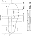
- Fig. 1A also provides information that may be useful for explaining and understanding the specification and/or aspects of this technology.
- Fig. 1A provides a representation of a footwear/foot-receiving device component 100, which in this illustrated example constitutes a portion of a sole structure for an article of footwear.
- the same general definitions and terminology described below may apply to footwear and foot-receiving devices in general and/or to other footwear/foot-receiving device components or portions thereof, such as an upper, a midsole component, an outsole component, a sole structure, etc.
- the rearmost heel location RH and the forwardmost toe location FT may be located by determining the rear heel and forward toe tangent points with respect to front and back parallel vertical planes VP when the component 100 (e.g., sole structure or foot-supporting member in this illustrated example, optionally as part of an article of footwear or foot-receiving device) is oriented on a horizontal support surface S in an unloaded condition (e.g., with no weight applied to it other than potentially the weight of the shoe/foot-receiving device components with which it is engaged).
- component 100 e.g., sole structure or foot-supporting member in this illustrated example, optionally as part of an article of footwear or foot-receiving device
- the forwardmost and/or rearmost locations of a specific footwear or foot-receiving device component 100 constitute a line segment (rather than a tangent point), then the forwardmost toe location and/or the rearmost heel location constitute the mid-point of the corresponding line segment. If the forwardmost and/or rearmost locations of a specific footwear or foot-receiving device component 100 constitute two or more separated points or line segments, then the forwardmost toe location and/or the rearmost heel location constitute the mid-point of a line segment connecting the furthest spaced and separated points and/or furthest spaced and separated end points of the line segments (irrespective of whether the midpoint itself lies on the component 100 structure). If the forwardmost and/or rearwardmost locations constitute one or more areas, then the forwardmost toe location and/or the rearwardmost heel location constitute the geographic center of the area or combined areas (irrespective of whether the geographic center itself lies on the component 100 structure).
- slat means a thin, narrow strip of a foot support component extending across and forming a portion of a base support surface of the foot support component.
- a “slat” will have a thickness dimension "T” (e.g., in a foot support component/footwear top-to-bottom direction), a width dimension "W” (e.g., a direct dimension across the component from one open space to an opposite and adjacent open space-in some examples, a dimension in the foot support component's heel-to-toe direction and/or in the sole structure's/footwear's longitudinal direction), and a breadth dimension "B” (e.g., transverse to the width dimension-in some examples, a dimension in the foot support component's lateral side-to-medial side direction and/or in the sole structure's/footwear's transverse direction).
- T thickness dimension
- W e.g., a direct dimension across the component from one open space to an opposite and adjacent open space-in some examples, a dimension in the
- central area of a foot support member or slat means a central 35% to 65% of the foot support member or slat in its longest dimension B (e.g., in some examples, this longest dimension of the member/slat will be a breadth dimension and/or in the lateral side-to-medial side direction of the foot support member or slat).
- Foot support members/slats defined by openings or open spaces that originate within the sidewall fall within the scope of the term "originate at or proximate to,” unless the phrase is further modified to expressly state that the foot support member/slat originates in the base support surface.
- the phrase "located at or proximate to” similarly means that any portions of the noted items (e.g., an "origination point" and a "sidewall”) are within 20 mm of one another (and in some examples, when stated, may be within 15 mm, within 10 mm, within 5 mm, or even contacting).
- a foot support member/slat may originate (have an "origination point") at a location "spaced away" from a free edge of a sidewall by a direct distance of at least 2 mm, and in some examples, by at least 3 mm, at least 5 mm, at least 10 mm, or even at least 15 mm.
- Foot support components for articles of footwear include: (a) a lateral sidewall that extends to and forms a lateral free edge (e.g., a lateral top edge); (b) a medial sidewall located opposite the lateral sidewall, wherein the medial sidewall extends to and forms a medial free edge (e.g., a medial top edge); and (c) a base support surface that includes an exterior surface and an interior surface opposite the exterior surface.
- the base support surface includes a plurality of foot support members (i.e. arched foot support slats) for supporting at least a portion of the plantar surface of a wearer's foot.
- the base support surface includes: (a) a first arched foot support slat, wherein a local extrema (e.g., a peak of the arch) of the first arched foot support slat is located in a central area of the first arched foot support slat between the lateral sidewall and the medial sidewall, and wherein the first arched foot support slat originates at or proximate to the lateral sidewall and the medial sidewall at respective locations spaced away from the lateral free edge and the medial free edge, (b) a second arched foot support slat, wherein a local extrema (e.g., a peak of the arch) of the second arched foot support slat is located in a central area of the second arched foot support slat between the lateral sidewall and the medial sidewall, and wherein the second arched foot support slat originates at or proximate to the lateral sidewall and the medial sidewall at respective locations space
- Foot support components for articles of footwear in accordance with the claimed invention include: (a) a lateral sidewall that extends to and forms a lateral free edge (e.g., lateral top edge); (b) a medial sidewall located opposite the lateral sidewall, wherein the medial sidewall extends to and forms a medial free edge (e.g., medial top edge); and (c) a base support surface that includes an exterior surface and an interior surface opposite the exterior surface.
- the base support surface includes a plurality of foot support members (i.e., arched foot support slats) for supporting at least a portion of the plantar surface of a wearer's foot.
- a majority, or even all-of the foot support members may include: (i) a lateral end point located at or proximate to the lateral sidewall, (ii) a medial end point located at or proximate to the medial sidewall, (iii) a forward edge defined at least in part by a forward open space located between the foot support member and a forwardly adjacent foot support member, (iv) a rearward edge defined at least in part by a rearward open space located between the foot support member and a rearwardly adjacent foot support member, and (v) a single local extrema (for that arched foot support member) located in a central area of the arched foot support member between the lateral sidewall and the medial sidewall.
- the base support surface may include:
- the forward edge of one foot support member may be separated from the rearward edge of the forwardly adjacent foot support member over at least 75%, at least 80%, at least 90%, at least 95%, or even at least 98% of the breadth dimensions of either or both of the noted foot support members.
- one or more additional arched foot support members having any one or more of the features of the first, second, and third arched foot support members, may be included (e.g., arranged forward and/or rearward of the first, second, and third arched foot support members) in the base support surface and/or foot support component without departing from this technology.
- the base support surface may include:
- Additional aspects of this technology relate to more specific features of the various footwear components described above and described in more detail below as well as additional features or structures included in the footwear components.
- Such additional aspects may include: more specific features of a footwear component including the lateral and medial sidewalls and the base support surface, e.g., features of a connecting wall (e.g., a rear heel wall, a forward toe wall); features of connecting the above footwear component with other footwear components, such as foam midsole components, bladder midsole components, other midsole components, outsole components, footwear upper components, etc.; various dimensional features of the footwear components; etc.
- a connecting wall e.g., a rear heel wall, a forward toe wall
- features of connecting the above footwear component with other footwear components such as foam midsole components, bladder midsole components, other midsole components, outsole components, footwear upper components, etc.
- various dimensional features of the footwear components etc.
- the article of footwear 200 of Fig. 2A includes an upper 202 and a sole structure 204 engaged with the upper 202.
- foot support components 250 in accordance with aspects of this technology may constitute all or a portion of the sole structure 204.
- the upper 202 and sole structure 204 may be engaged together in any desired manner, including in manners conventionally known and used in the footwear arts (such as by one or more of adhesives or cements, stitching or sewing, mechanical connectors, etc.).
- the upper 202 potentially together with the sole structure 204, define a foot-receiving interior chamber 206 for containing a wearer's foot.
- the bottom of the upper 202 may include a strobel 208 or other component engaged with or integrally formed with another portion of the upper 202 e.g., a lateral side upper component 202L and/or a medial side upper component 202M.
- the upper 202 may include other components as well.
- the upper 202 may include: a tongue member located across the foot instep area and positioned to moderate the feel of the footwear's closure system on the wearer's foot; a closure system (e.g., including one or more of a lace type closure system, a zippered closure system, a buckle type closure system, elastic stretch elements, etc.); a heel counter; a toe cap; straps; etc.
- the upper 202 may include a "sock-like" upper component, e.g., made from fabric and configured to closely fit the wearer's foot like a conventional sock.
- the upper 202 may be made from any desired material(s) and/or in any desired constructions and/or manners without departing from this technology. As some more specific examples, all or at least a portion of the upper 202 (and optionally a majority, substantially all, or even all of the upper 202) may be formed as a woven textile component, a knitted textile component, another textile component, a natural leather component, a synthetic leather component, a polymeric component (e.g., a TPU, etc.), etc.
- the components for upper 202 may have structures and/or constructions like those used in footwear products commercially available from NIKE, Inc. of Beaverton, OR and/or other manufacturers.
- uppers 202 and articles of footwear 200 in accordance with at least some examples of this technology may include fused layers of upper materials, e.g., uppers of the types that include upper materials bonded by hot melt or other adhesive materials, such as in footwear products commercially available from NIKE, Inc. of Beaverton, Oregon.
- uppers of the types described in U.S. Patent Nos. 7,347,011 and/or 8,429,835 may be used without departing from this technology.
- FIG. 2A shows the top surface 252T of outsole component 252 having a generally planar surface
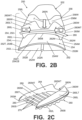
- Fig. 2B shows an alternative in which the top surface 252T is contoured (e.g., upwardly arched in the lateral side-to-medial side direction).
- the open space 252O of outsole component 252 may define a horizontal cross sectional area between side arms 252L and 252M of at least 10 cm 2 , and in some examples at least 15 cm 2 , at least 20 cm 2 , at least 25 cm 2 , at least 30 cm 2 , at least 40 cm 2 , at least 50 cm 2 , or even at least 60 cm 2 (this area may be measured as the horizontal cross-sectional area of the opening 252O with the outsole component 252 supported on its ground-facing surface on a horizontal base surface in an unloaded condition (e.g., without weight applied to the outsole component 252, other than perhaps the weight of other components making up the foot support component 250, sole structure 204, and/or article of footwear)).
- this area may be measured as the horizontal cross-sectional area of the opening 252O with the outsole component 252 supported on its ground-facing surface on a horizontal base surface in an unloaded condition (e.g., without weight applied to the outsole component 252, other than perhaps the weight of other components making up
- the lower midsole component 254 includes an intermediate recess or central open space 254O between a lateral side arm 254L and a medial side arm 254M, as well as a rear connecting wall 254W connecting the lateral side arm 254L and the medial side arm 254M.
- the lower midsole component 254 may have a generally U-shape, including a generally U-shaped outer perimeter and a generally U-shaped inner perimeter (and the lower midsole component 254 may terminate, e.g., in a midfoot area or heel area of the sole structure 204, at lateral free end 254LE and medial free end 254LM).
- the central open space (e.g., 254O) of lower midsole component 254 also could be provided, if desired, by a generally oval, round, or elliptically shaped lower midsole component, by a rounded rectangular shaped lower midsole component, by another open ended or close ended lower midsole configuration, and/or by providing separate medial and lateral side components (e.g., omitting connecting wall 254W), etc.
- the open space 254O may have any desired shape as well.
- Foot support component 250 of this example includes an upper midsole component 256, e.g., located closest to the wearer's foot in this illustrated example.
- this upper midsole component 256 may be located directly beneath, and in some examples directly engaged with, the upper 202 (e.g., with the bottom surface, such as a strobel 208, of the upper 202).
- the upper midsole component 256 of this example includes a top surface 256T engaged with the bottom surface of the upper 202 (e.g., strobel 208). Any desired manner of engagement between upper midsole component 256 and upper 202 may be employed without departing from this technology, including fixed or releasable connections.
- these components 202/256 may be engaged together via one or more of: cements or adhesives; mechanical fasteners or hardware; fused or welded connections; etc.
- the upper midsole component 256 of this example includes a bottom surface 256B engaged with the top surface 260T of the midsole component 260 (which is described in more detail below). Any desired manner of engagement between upper midsole component 256 and midsole component 260 may be employed without departing from this technology, including fixed or releasable connections.
- these components 256/260 may be engaged together via one or more of: cements or adhesives; mechanical fasteners or hardware; fused or welded connections; etc.
- the lower midsole component 254 may be "firmer” than the upper midsole component 256. This may be determined, for example, by determining which component responds with greater deflection under an applied force or load (e.g., with the "firmer” component vertically displacing or deflecting less than the vertical displacement or deflection of the "softer" component under the same applied force conditions).
- the upper midsole component 256 has a lateral side wall 256L and a medial side wall 256M, as well as a rear wall 256W connecting the lateral side wall 256L and the medial side wall 256M.
- the upper midsole component 256 may have a half-oval or a half-elliptical shape, e.g., including a generally U-shaped outer perimeter.
- This example upper midsole component 256 terminates, e.g., in a midfoot area or heel area of the sole structure 204, at free end 256E.
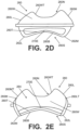
- the midsole component 260 (which itself may be considered a "foot support component” or a portion thereof in accordance with the claimed invention) now will be described in more detail in conjunction with Figs. 2A-2J .
- This midsole component 260 may constitute a one piece or multi-piece construction, e.g., made from rigid plastic material(s), such as a thermoplastic polyurethane (“TPU”) material; a polyether block amide thermoplastic elastic polymer material (e.g., available under the PEBAX ® brand (from Arkema) and/or VESTAMID ® E brand (from Evonik)); a fiber-reinforced composite plastic component (e.g., carbon fiber reinforced composite, glass fiber reinforced composite, etc.); etc.
- TPU thermoplastic polyurethane
- PEBAX ® brand from Arkema
- VESTAMID ® E brand from Evonik
- fiber-reinforced composite plastic component e.g., carbon fiber reinforced composite, glass fiber reinforced composite, etc.
- the material making up the midsole component may be a rigid plastic material having a Shore D hardness within a range of 20 to 80 Shore D, and in some examples, between 25 and 80, between 30 and 80, between 35 and 80, between 40 and 75, or even between 50 and 75 Shore D.
- a foot support component 250 and/or midsole component 260 has at least 3 individual arched foot support members/slats 270; optionally (a) at least 5 individual arched foot support members/slats 270; (b) from 3 to 45 individual arched foot support members/slats 270; (c) from 3 to 35 individual arched foot support members/slats 270; (d) from 3 to 25 individual arched foot support members/slats 270; (e) from 3 to 20 individual arched foot support members/slats 270; (f) from 3 to 16 individual arched foot support members/slats 270; (g) from 3 to 12 individual arched foot support members/slats 270; and or (h) from 3 to 8 individual arched foot support members/slats 270.
- one or more of the foot support members/slats 270 may be planar, substantially planar, or unarched (e.g., planar, substantially planar, or unarched when in an unloaded condition and oriented on a horizontal support surface with its ground-facing surface oriented downward), as long as at least three foot support members are arched.
- At least three, optionally a majority, or even all of the individual foot support members/slats 270 of a foot support component 250/midsole component 260 extend in a generally lateral side-to-medial side direction of the sole structure 204/article of footwear 200, i.e., originating at or proximate to the lateral sidewall 260L and/or the medial side-wall 260M. As shown in Figs.
- At least three, optionally a majority, or even all of the individual foot support members/slats 270 of a foot support component 250/midsole component 260 originate at locations spaced away from the lateral free edge 260LT and/or at locations spaced away from the medial free edge 260MT.
- the open space(s) 280 are positioned and shaped to completely separate at least 90% of a rearward edge 270RE of one arched foot support member/slat 270 from at least 90% of a forward edge 270FE of a rearwardly adjacent arched foot support member/slat 270. See Fig. 2J .
- the open space(s) 280 may be positioned and shaped to completely separate at least 95%, at least 98%, or even 100% of a rearward edge 270RE of one arched foot support member/slat 270 from at least 95%, at least 98%, or even 100% of a forward edge 270FE of a rearwardly adjacent arched foot support member/slat 270.
- These spaces 280 shape and/or member/slat 270 separation features may be provided between any number of adjacent foot support member/slat 270 pairs in the overall midsole component 260 structure.
- the foot support member/slat 270's width dimension W2 will correspond to the distance from a foot support member/slat 270's forward edge 270FE to its rear edge 270RE across the foot support member/slat 270 and perpendicular to the breadth dimension B2. If the width of the foot support member/slat 270 varies over the breadth dimension B2, then the width dimension W2 may be considered as the widest width dimension present across the foot support member/slat 270 that is perpendicular to the breadth dimension B2.
- open space 280's breadth dimension B1 and/or foot support member/slat 270's breadth dimension B2 may have one or more of the following properties: (a) at least 15 mm long, (b) at least 20 mm long, (c) at least 30 mm long, (d) at least 40 mm long, (e) at least 50 mm long, (f) less than 150 mm long, (g) less than 120 mm long, (h) less than 100 mm long, (i) less than 90 mm long, (j) from 15 mm to 150 mm long, (k) from 18 mm to 120 mm long, (1) from 20 mm to 100 mm long, (m) from 25 mm to 90 mm long, and/or (n) from 30 mm to 85 mm long.
- the ratios of B1/W1 and/or B2/W2 may be within one or more of the ranges of: (a) 0.5 to 150, (b) 0.75 to 120, (c) 1 to 100, (d) 1 to 80, (e) 1 to 60, (f) 1.25 to 50, (g) 1.5 to 40, (h) 1.5 to 40, (i) 1.75 to 25, (i) 2 to 20, (j) 2.2 to 18, and/or (k) 2.3 to 15.
- the ratio of W1 to W2 may be within one or more of the ranges of: (a) 0.05 to 5, (b) 0.1 to 3, (c) 0.15 to 2, (d) 0.2 to 1.8, (e) 0.25 to 1.5; and/or (f) 0.5 to 1.25.
- the wall height dimension HW or vertical height may be up to 50 mm or even more, particularly in examples in which the midsole component's sidewall(s) 260L, 260M, and/or 260W may provide functions of a footwear heel counter.
- the open spaces 280 and foot support members/slats 270 may be structured and arranged such that the forward edge 270FE of one or more of the individual foot support members/slats 270 will be substantially parallel to the rearward edge 270RE of a forwardly adjacent foot support member/slat 270 over at least 75%, at least 80%, at least 85%, at least 90%, at least 95%, or even 100% of one or both of the adjacent foot support members/slats 270 longest dimensions and/or edge lengths.
- the "forward edge" 270FE and the "rearward edge” 270RE of an individual foot support member/slat 270 may be found by: (a) extending a lateral end line 282L from the outermost lateral location of the forward open space 280 to the outermost lateral location of the rearward open space 280 that define the individual foot support member/slat 270 and (b) extending a medial end line 282M from the outermost medial location of the forward open space 280 to the outermost medial location of the rearward open space 280 that define the individual foot support member/slat 270.
- the relevant edges 270FE, 270RE, 280FE, 280RE begin/end where the end lines 282L, 282M reach the open spaces 280 defining the foot support member/slat 270.
- the longest or breadth dimension of the open space 280 (B1) is the dimension from 280LE to 280ME.
- the longest or breadth dimension of the foot support member/slat 270 (B2) may be measured from the lateral midpoint (270LMP) of lateral end line 282L to the medial midpoint (270MMP) of the medial end line 282M. See Fig. 2J .
- At least one of the arched foot support members/slats 270 may include: (i) a lateral origination point 270LE and/or a lateral end or midpoint 270LMP located at or proximate to the lateral sidewall 260L, (ii) a medial origination point 270ME and/or a medial end or midpoint 270MMP located at or proximate to the medial sidewall 260M, (iii) a forward edge 270FE extending from a forward lateral origination point 270LE to a corresponding forward medial origination point 270ME, (iv) a rearward edge 270RE extending from an adjacent rearward lateral origination point 270LE to a corresponding adjacent rearward medial origination point 270ME, and (v) a single local extrema 270E for that arched foot support member/slat 270
- FIGs. 2A-2J illustrate foot support members/slats 270 and spaces 280 having substantially constant dimensions and parallel orientations within an individual midsole component 260
- the sizes, shapes, dimensions, orientations, and/or other features of the foot support members/slats 270 and/or spaces 280 may be varied within an individual midsole component 260. These features also may be varied, e.g., for customization/optimization purposes, as will be described in more detail below.
- Some examples include: including one or more hinge structures (e.g., in the connecting wall 260W and/or within the breadth dimension of one or more foot support members/slats 270); including a compressible material as part of the connecting wall 260W and/or within the breadth dimension of one or more foot support members/slats 270; providing one or more gaps in the connecting wall 260W and/or within the breadth dimension of one or more foot support members/slats 270; providing one or more perforated areas and/or predefined bend lines in the connecting wall 260W and/or within the breadth dimension of one or more foot support members/slats 270; etc.
- hinge structures e.g., in the connecting wall 260W and/or within the breadth dimension of one or more foot support members/slats 270
- a compressible material as part of the connecting wall 260W and/or within the breadth dimension of one or more foot support members/slats 270
- Such structures may promote bending in one direction while resisting bending in the opposite direction (at least resisting bending in the opposite direction once the sole structure 204/foot support component 250/midsole component 260 returns to its unbent or preloaded condition (e.g., after the force from landing the step or jump is removed or sufficiently reduced)).
- the connecting wall 260W may constitute a forward toe wall and be located in the forefoot area (e.g., the extreme forward toe area) of a sole structure 204/foot support component 250/midsole component 260.
- Some sole structures 204/foot support components 250/midsole components 260 in accordance with this technology may include connecting walls 260W at both the rear heel area and the forward toe area of the structure. In such examples with two connecting walls 260W, either or both or neither of the connecting walls 260W may include a notched area 260N and/or other pre-defined bend features of the types described above.
- the exterior surface 260B of the base support surface 260S includes: (a) a lateral base edge 262L (e.g., a lower lateral base edge) located on an opposite side of the lateral sidewall 260L from the lateral free edge 260LT, (b) a medial base edge 262M (e.g., a lower medial base edge) located on an opposite side of the medial sidewall 260M from the medial free edge 260MT, and (c) a connecting base edge 262W (e.g., a lower edge) located on an opposite side of the connecting wall 260W from the connecting wall free edge 260WT.
- a lateral base edge 262L e.g., a lower lateral base edge
- medial base edge 262M e.g., a lower medial base edge
- a connecting base edge 262W e.g., a lower edge
- the lower midsole component 254 has a U-shaped structure in which the lateral base edge 254LB and the lateral sidewall 254L of the lower midsole component 254 form a lateral arm of the U-shaped structure, the medial base edge 254MB and the medial sidewall 254M of the lower midsole component 254 form a medial arm of the U-shaped structure, and the connecting base edge 254CB and the connecting wall 254W of the lower midsole component form a base of the U-shaped structure (connecting the above-noted medial and lateral side edges and sidewalls).
- the U-shaped structure of the lower midsole component 254 defines an open space 254O between the lateral arm (and lateral sidewall 254L) and the medial arm (and medial sidewall 254M).
- the article of footwear 200/sole structure 204/foot support component 250 of this example may include an outsole system 252.
- the outsole system 252 may comprise one or more outsole components including a surface structured and arranged to contact the ground (or other contact surface) in use (e.g., when worn by a wearer).
- At least some examples of this technology will attenuate impact forces, e.g., by compressing the midsole components 254, 256 and/or vertically displacing the foot support members/slats 270 of the midsole component 260.
- the foot support component 250/midsole component 260 may apply a securing force to the wearer's foot.
- a downward force F e.g., from landing a step or jump
- one or more of the foot support members 270 e.g., upwardly arched foot support members/slats 270
- Figs. 3A-3C illustrate an example assembly process of sole structures 204/foot support components 250 in accordance with at least some examples of this technology.
- the process may start with up to four components of the sole structures 204/foot support components 250, e.g., a first midsole component or system (e.g., lower midsole component 254 in this example), a second midsole component or system (e.g., upper midsole component 256 in this example), a foot support component or system (e.g., midsole component 260 in this example), and an outsole component or system (e.g., outsole component 252 in this example).
- a first midsole component or system e.g., lower midsole component 254 in this example
- a second midsole component or system e.g., upper midsole component 256 in this example
- a foot support component or system e.g., midsole component 260 in this example
- an outsole component or system e.g., outsole component 252 in this example.
- the outsole component 252 may hold the first midsole component 254 with the second midsole component 256 without the first midsole component 254 being directly fixed to the second midsole component 256.
- the first midsole component 254 may be readily movable with respect to the second midsole component 256, e.g., as shown in Fig. 3B .
- a recess 300 may be defined between the bottom surface 256B of the second midsole component 256 and the top surface 254T of the first midsole component 254 at this stage.
- the various sole components 252, 254, 256, and/or 260 may be engaged together (and/or with other sole components, upper components, and/or footwear components) in different orders and/or in different manners.
- the midsole component 260 first may be engaged with one of first midsole component 254 or second midsole component 256, (b) then that combination may be engaged with the other midsole component (254 or 256), and (c) then that combination may be engaged with the outsole component 252.
- These engagements may be fixed or releasable, and may include any one or more of adhesives, mechanical connectors, and/or fuse bonded/welded joints.
- the bottom surface 256B of the second midsole component 256 may include one or more ribs 256R or other structures that fit within the space(s) 280 provided between adjacent foot support members/slats 270 of the midsole component 260.
- the rib(s) 256R may help engage the second midsole component 256 with the midsole component 260, help prevent undesired relative movement between these two components 256, 260, and/or help prevent undesired deflection of the foot support members/slats 270 in the heel-to-toe direction of the sole structure 204/foot support component 250.
- This example sole structure 204/foot support component 250 assembly process (as well as other assembly processes that incorporate a foot support component like foot support member 260 into the sole structure 204/foot support component 250) provide opportunities for customization or otherwise tailoring footwear and foot support to a specific wearer and/or to a specific use (e.g., specific sports, specific activities, specific team positions, etc.).
- plantar forces produced by a footwear wearer may be measured (e.g., using foot force measuring systems as are known and used in the art), e.g., with the wearer involved in some type of activity in which a step or jump is landed and/or other forces are applied by the wearer's foot to a contact surface and forces are applied by the contact surface to the wearer's foot.
- Fig. 3D provides a bottom view of an assembled sole structure 204/foot support component 250 in accordance with some examples of this technology.
- the first midsole system 254 e.g., the lower midsole component 254
- the first midsole system 254 may be substantially U-shaped, having free ends 254LE, 254ME of the U-shape located in the heel or midfoot region of the sole structure 204/foot support component 250 and a central open space 254O.
- the forward extent of the first midsole system 254 in this illustrated example is shown by broken line 310 in Fig. 3D .
- this specific example as described above in conjunction with Figs.
- the outsole component 252 may include an intermediate recess or central open space 252O, e.g., between a lateral side arm 252L and a medial side arm 252M.
- the outsole component 252 may include a closed front end to close off the intermediate recess or central open space 252O, as shown by outsole portion 252F in Fig. 3D .
- the remainder of the bottom of the sole structure 204/foot support component 250 of this example (around and forward of the open spaces 252O, 254O and the line 310) constitutes the bottom surface 252B of the outsole 252.
- sole structures 204/foot support components 250 in which an outsole opening 252O and a lower midsole component opening 254O at least partially align e.g., as shown in Fig. 3D
- at least a portion of one or more of the foot support members/slats 270 may be exposed at the exterior of the final assembled sole structure 204 and the final assembled foot support component 250.
- the bottom surface 256B of the second (upper) midsole component 256 may be exposed in one or more of the spaces 280 between adjacent foot support members/slats 270.
- each of the foot support members/slats 270 extends continuously from its lateral origination point 270LE to its medial origination point 270ME (and/or from its lateral end or midpoint 270LMP to its medial end or midpoint 270MMP), and each of the spaces 280 extends continuously from its lateral end 280LE to its medial end 280ME.
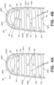
- Fig. 4A provides an alternative example of a foot support component in the form of a midsole component 360 similar to those described above for midsole component 260.
- one or more bridge components 362 may be located outside the central area of the foot support members/slats 270 and/or positioned away from one or both of the local extrema 270E of two adjacent arched foot support members/slats 270. Also, as shown in Fig. 4A , two adjacent foot support members/slats 270 may be connected by more than one bridge components 362.
- the bridge component(s) 362 may be integrally formed as part of the midsole component 360 (e.g., when the midsole component 360 is molded) and may be made of the same material as the midsole component 360 (or a different material).
- one or more bridge components 362 may be separate parts engaged with two or more adjacent foot support members/slats 270 (e.g., by adhesives or cements, mechanical connectors, fusing techniques, etc.).
- one or more gaps 462 may be located outside the central area of the foot support members/slats 270 and/or positioned away from the local extrema 270E of an arched foot support member/slat 270.
- the gap(s) 462 may be integrally formed as part of the midsole component 460 (e.g., when the midsole component 460 is molded) and/or they may be cut across the foot support member/slat 270 after it is formed.
- the term "gap" as used herein in this context may constitute a discontinuity in foot support member/slat 270 (having little or no measurable separation).
- Fig. 4B shows gaps 462 connecting four pair of adjacent spaces 280
- any number of gaps 462 may be included in an individual midsole component 460 connecting any number of pair of adjacent spaces 280.
- an individual midsole component 460 may include one or more gaps 462 and one or more bridge components 362, e.g., of the types described above in conjunction with Fig. 4A .
- the midsole component 260 of the foot support component 250 and the sole structure 204 is located primarily in a heel region of the article of footwear, although other options are mentioned.
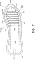
- the midsole component 260, 360, 460 of the example of Fig. 6 may include a lateral sidewall (e.g., like 260L), a medial sidewall (e.g., like 260M), a receptacle, and a slatted or other base surface 260S of the types described above.
- a substantial connecting wall (akin to wall 260W) may be omitted which is not in accordance with the claimed invention, e.g., to avoid a raised wall running across the plantar surface of a wearer's foot.
- One or both of the outsole component 252 and/or the lower midsole component 254 may include central openings 252O, 254O, if desired, so that the bottom 260B of the midsole component 260, 360, 460 (e.g., the foot support member(s)/slat(s) 270 and/or space(s) 280) are exposed at the bottom exterior of the overall sole structure 204, as shown in Fig. 6 .
- the sidewall height dimension(s) HW may be somewhat toward the lower end of the various ranges described above (e.g., less than 15 mm high, less than 12 mm high, less than 10 mm high, etc.).
- Portions of the bottom surface 260B of the midsole component 260, 360, 460 at the rearwardmost extent and/or around the periphery thereof may be covered by the lower midsole component 254 and/or the outsole component 252 in at least some examples of this forefoot based structure.
- This example midsole component 260, 360, 460 may include a lateral sidewall (e.g., like 260L), a medial sidewall (e.g., like 260M), a receptacle, and a slatted or other base surface 260S of the types described above.
- a forward connecting wall (akin to wall 260W) may be located around the forward toe area of the structure to connect the lateral sidewall 260L and the medial sidewall 260M.
- This forward connecting wall may have any of the structural features, properties, options, and the like of the connecting wall 260W described above, including the notch features and/or other prebend/flexion supporting features, except that it is located around the front of the foot support structure rather than around the rear of the structure.
- One or both of the outsole component 252 and/or the lower midsole component 254 may include central openings 252O, 254O, if desired (and may be U-shaped), so that the bottom 260B of the midsole component 260, 360, 460 (e.g., the foot support member(s)/slat(s) 270 and/or space(s) 280) are exposed at the bottom exterior of the overall sole structure 204, as shown in Fig. 7 .
Landscapes
- Health & Medical Sciences (AREA)
- Epidemiology (AREA)
- General Health & Medical Sciences (AREA)
- Public Health (AREA)
- Footwear And Its Accessory, Manufacturing Method And Apparatuses (AREA)
Claims (14)
- Fußstützkomponente (250, 260, 360, 460) für einen Schuhartikel (200) umfassend:eine laterale Seitenwand (260L), die sich zu einer lateralen freien Kante (260LT) erstreckt und diese bildet;eine mediale Seitenwand (260M), angeordnet gegenüber der lateralen Seitenwand (260L), wobei sich die mediale Seitenwand (260M) zu einer medialen freien Kante (260MT) erstreckt und diese bildet;eine Basisstützfläche (260S), die eine Außenfläche (260B) und eine Innenfläche (260T) gegenüber der Außenfläche (260B) einschließt, wobei die Basisstützfläche (2605) einschließt:eine erste gewölbte Fußstützleiste (270), wobei sich ein lokales Extremum (270E) der ersten gewölbten Fußstützleiste (270) in einem zentralen Bereich der ersten gewölbten Fußstützleiste (270) zwischen der lateralen Seitenwand (260L) und der medialen Seitenwand (260M) befindet, und wobei die erste gewölbte Fußstützleiste (270) an oder in der Nähe der lateralen Seitenwand (260L) und der medialen Seitenwand (260M) an Stellen beginnt, die von der lateralen freien Kante (260LT) und der medialen freien Kante (260MT) beabstandet sind,eine zweite gewölbte Fußstützleiste (270), wobei sich ein lokales Extremum (270E) der zweiten gewölbten Fußstützleiste (270) in einem zentralen Bereich der zweiten gewölbten Fußstützleiste (270) zwischen der lateralen Seitenwand (260L) und der medialen Seitenwand (260M) befindet, und wobei die zweite gewölbte Fußstützleiste (270) an oder in der Nähe der lateralen Seitenwand (260L) und der medialen Seitenwand (260M) an Stellen beginnt, die von der lateralen freien Kante (260LT) und der medialen freien Kante (260MT) beabstandet sind,eine dritte gewölbte Fußstützleiste (270), wobei sich ein lokales Extremum (270E) der dritten gewölbten Fußstützleiste (270) in einem zentralen Bereich der dritten gewölbten Fußstützleiste (270) zwischen der lateralen Seitenwand (260L) und der medialen Seitenwand (260M) befindet, und wobei die dritte gewölbte Fußstützleiste (270) an oder in der Nähe der lateralen Seitenwand (260L) und der medialen Seitenwand (260M) an Stellen beginnt, die von der lateralen freien Kante (260LT) und der medialen freien Kante (260MT) beabstandet sind,einen ersten offenen Raum (280), welcher sich zwischen mindestens 90% einer hinteren Kante (270RE) der ersten gewölbten Fußstützleiste (270) und mindestens 90% einer vorderen Kante (270FE) der zweiten gewölbten Fußstützleiste (270) erstreckt und diese trennt, undeinen zweiten offenen Raum (280), welcher sich zwischen mindestens 90% einer hinteren Kante (270RE) der zweiten gewölbten Fußstützleiste (270) und mindestens 90% einer vorderen Kante (270FE) der dritten gewölbten Fußstützleiste (270) erstreckt und diese trennt,wobei der erste offene Raum (280) und der zweite offene Raum (280) jeweils ein Durchgangsloch bilden, welches sich vollständig durch die Basisstützfläche (260S) von der Außenfläche (260B) der Basisstützfläche (260S) zur Innenfläche (260T) der Basisstützfläche (260S) erstreckt;eine Verbindungswand (260W), welche die laterale Seitenwand (260L) und die mediale Seitenwand (260M) verbindet, wobei sich die Verbindungswand (260W) zu einer freien Kante der Verbindungswand (260WT) erstreckt und diese bildet, welche sich von der lateralen freien Kante (260LT) zur medialen freien Kante (260MT) erstreckt, wobei die Außenfläche (260B) der Basisstützfläche (260S) eine laterale Basiskante (262L) einschließt, welche sich auf einer der lateralen freien Kante (260LT) gegenüberliegenden Seite der lateralen Seitenwand (260L) befindet, eine mediale Basiskante (262M), welche sich auf einer der medialen freien Kante (260MT) gegenüberliegenden Seite der medialen Seitenwand (260M) befindet, und eine Verbindungsbasiskante (262W), welche sich auf der gegenüberliegenden Seite der Verbindungswand (260W) von der freien Kante der Verbindungswand (260WT) befindet; undein erstes Zwischensohlensystem (254), welches eine laterale Basiskante (254LB), eine mediale Basiskante (254MB) und eine Verbindungsbasiskante (254CB) einschließt, wobei die laterale Basiskante (254LB) des ersten Zwischensohlensystems (254) mit der lateralen Basiskante (262L) der Basisstützfläche (260S) in Eingriff ist, wobei die mediale Basiskante (254MB) des ersten Zwischensohlensystems (254) mit der medialen Basiskante (262M) der Basisstützfläche (260S) in Eingriff ist, und wobei die Verbindungsbasiskante (254CB) des ersten Zwischensohlensystems (254) mit der Verbindungsbasiskante (262W) der Basisstützfläche (260S) in Eingriff ist,wobei:das erste Zwischensohlensystem (254) eine U-förmige Struktur aufweist, bei welcher die laterale Basiskante (254LB) des ersten Zwischensohlensystems (254) einen lateralen Arm der U-förmigen Struktur bildet, die mediale Basiskante (254MB) des ersten Zwischensohlensystems (254) einen medialen Arm der U-förmigen Struktur bildet und die Verbindungsbasiskante (254CB) des ersten Zwischensohlensystems (254) eine Basis der U-förmigen Struktur bildet, und/oderwenigstens ein Abschnitt jeder der ersten gewölbten Fußstützleiste (270), der zweiten gewölbten Fußstützleiste (270) und der dritten gewölbten Fußstützleiste (270) zwischen der lateralen Basiskante (254LB) des ersten Zwischensohlensystems (254) und der medialen Basiskante (254MB) des ersten Zwischensohlensystems (254) freiliegt.
- Fußstützkomponente (250, 260, 360, 460) nach Anspruch 1, wobei die freie Kante der Verbindungswand (260WT) einen gekerbten oder konkaven oberen Kantenabschnitt (20N) enthält.
- Fußstützkomponente (250, 260, 360, 460) nach Anspruch 1, wobei die Verbindungswand (260W) einen gekerbten oder konkaven Abschnitt (260N) enthält.
- Fußstützkomponente (250, 260, 360, 460) nach einem der Ansprüche 1 bis 3, wobei die Verbindungswand (260W) eine hintere Fersenwand ist.
- Fußstützkomponente (250, 260, 360, 460) nach einem der Ansprüche 1 bis 3, wobei die Verbindungswand (260W) eine vordere Zehenwand ist.
- Fußstützkomponente (250, 260, 360, 460) nach Anspruch 1, wobei, wenn mindestens ein Abschnitt jeder der ersten gewölbten Fußstützleiste (270), der zweiten gewölbten Fußstützleiste (270) und der dritten gewölbten Fußstützleiste (270) zwischen der lateralen Basiskante (254LB) des ersten Zwischensohlensystems (254) und der medialen Basiskante (254MB) des ersten Zwischensohlensystems (254) freiliegt, das erste Zwischensohlensystem (254) die U-förmige Struktur aufweist.
- Fußstützkomponente (250, 260, 360, 460) nach einem der Ansprüche 1 bis 5, wobei eine Innenfläche der lateralen Seitenwand (260L), eine Innenfläche der medialen Seitenwand (260M), eine Innenfläche der Verbindungswand (260W) und die Innenfläche (260T) der Basisstützfläche (260S) einen Aufnahmebereich (264) definieren.
- Fußstützkomponente (250, 260, 360, 460) nach einem der Ansprüche 1 bis 5, wobei eine Innenfläche der lateralen Seitenwand (260L), eine Innenfläche der medialen Seitenwand (260M) und die Innenfläche (260T) der Basisstützfläche (260S) einen Aufnahmebereich (264) definieren.
- Fußstützkomponente (250, 260, 360, 460) nach Anspruch 7 oder Anspruch 8, weiter umfassend: eine Zwischensohlenkomponente (256), welche in den Aufnahmebereich (264) aufgenommen ist.
- Fußstützkomponente (250, 260, 360, 460) nach Anspruch 9, wobei ein Material der Zwischensohlenkomponente (256) eine geringere Shore-A-Härte und/oder eine geringere Dichte als eine Shore-A-Härte und/oder Dichte eines Materials des ersten Zwischensohlensystems (254) aufweist.
- Fußstützkomponente (250, 260, 360, 460) nach Anspruch 9 oder Anspruch 10, wobei die laterale Basiskante (254LB) des ersten Zwischensohlensystems (254) eine erste Verriegelungsstruktur (520) einschließt, die mit einer ersten komplementären Verriegelungsstruktur (520) eingreift, die an der lateralen Basiskante (262L) der Basisstützfläche (260S) bereitgestellt ist, und wobei die mediale Basiskante (254MB) des ersten Zwischensohlensystems (254) eine zweite Verriegelungsstruktur (520) einschließt, die mit einer zweiten komplementären Verriegelungsstruktur (520) eingreift, die an der medialen Basiskante (262M) der Basisträgerfläche (260S) bereitgestellt ist.
- Fußstützkomponente (250, 260, 360, 460) nach einem der Ansprüche 1, 10 oder 11, weiter umfassend:
ein Außensohlensystem (252), das ein laterales Außensohlenelement (252L) enthält, das mit einer Oberfläche des ersten Mittelsohlensystems (254) in Eingriff ist, die der lateralen Basiskante (254LB) des ersten Mittelsohlensystems (254) gegenüberliegt, und einem medialen Außensohlenelement (252M), das mit einer Oberfläche des ersten Mittelsohlensystems (254) in Eingriff ist, die der medialen Basiskante (254MB) des ersten Mittelsohlensystems (254) gegenüberliegt. - Fußstützkomponente (250, 260, 360, 460) nach Anspruch 1, wobei wenigstens der Abschnitt jeder der ersten gewölbten Fußstützlatte (270), der zweiten gewölbten Fußstützlatte (270) und der dritten gewölbten Fußstützlatte (270) zwischen der lateralen Basiskante (254LB) des ersten Mittelsohlensystems (254) und der medialen Basiskante (254MB) des ersten Mittelsohlensystems (254) freiliegt.
- Schuhartikel (200), umfassend:eine Oberstruktur (202); undeine Sohlenstruktur (204), die mit der Oberstruktur (202) in Eingriff ist, wobei die Sohlenstruktur (204) eine Fußstützkomponente (250, 260, 360, 460) nach einem der vorhergehenden Ansprüche enthält.
Applications Claiming Priority (2)
| Application Number | Priority Date | Filing Date | Title |
|---|---|---|---|
| US201962905649P | 2019-09-25 | 2019-09-25 | |
| PCT/US2020/052673 WO2021062121A1 (en) | 2019-09-25 | 2020-09-25 | Foot support components for articles of footwear |
Publications (2)
| Publication Number | Publication Date |
|---|---|
| EP4033934A1 EP4033934A1 (de) | 2022-08-03 |
| EP4033934B1 true EP4033934B1 (de) | 2025-04-16 |
Family
ID=72812006
Family Applications (1)
| Application Number | Title | Priority Date | Filing Date |
|---|---|---|---|
| EP20789381.9A Active EP4033934B1 (de) | 2019-09-25 | 2020-09-25 | Fussstützenbestandteile für schuhwerk |
Country Status (4)
| Country | Link |
|---|---|
| US (1) | US11490679B2 (de) |
| EP (1) | EP4033934B1 (de) |
| CN (1) | CN114364280B (de) |
| WO (1) | WO2021062121A1 (de) |
Family Cites Families (48)
| Publication number | Priority date | Publication date | Assignee | Title |
|---|---|---|---|---|
| DE3369831D1 (en) | 1983-04-21 | 1987-04-02 | Clarks Ltd | Improvements relating to footwear |
| US4878300A (en) | 1988-07-15 | 1989-11-07 | Tretorn Ab | Athletic shoe |
| EP0373336B1 (de) | 1988-12-13 | 1992-12-30 | Helmut Mayer | Einlage für einen Schuh |
| DE4114551C2 (de) | 1990-11-07 | 2000-07-27 | Adidas Ag | Schuhboden, insbesondere für Sportschuhe |
| CA2051230C (en) | 1991-09-12 | 1997-11-18 | Robert Burke | Power midsole cushioning and stability concept |
| US5572804A (en) | 1991-09-26 | 1996-11-12 | Retama Technology Corp. | Shoe sole component and shoe sole component construction method |
| US5651196A (en) | 1996-01-11 | 1997-07-29 | Hsieh; Frank | Highly elastic footwear sole |
| AU2461899A (en) | 1998-01-20 | 1999-08-02 | A. Ray Snow | Shoe with force responsive sole |
| US6298582B1 (en) | 1998-01-30 | 2001-10-09 | Nike, Inc. | Article of footwear with heel clip |
| FR2774566B1 (fr) | 1998-02-06 | 2000-05-12 | Samson H | Semelle de confort, son procede de fabrication et la chaussure equipee d'une telle semelle |
| JP3979765B2 (ja) | 2000-05-15 | 2007-09-19 | 株式会社アシックス | 靴底の緩衝装置 |
| US7013581B2 (en) | 2003-06-11 | 2006-03-21 | Nike, Inc. | Article of footwear having a suspended footbed |
| US7421805B2 (en) | 2003-07-17 | 2008-09-09 | Red Wing Shoe Company, Inc. | Integral spine structure for footwear |
| US7331124B2 (en) * | 2003-08-22 | 2008-02-19 | Akeva L.L.C. | Plate support for athletic shoe |
| US8225533B2 (en) * | 2003-08-22 | 2012-07-24 | Akeva, L.L.C. | Component for use in a shoe |
| US7562469B2 (en) * | 2003-12-23 | 2009-07-21 | Nike, Inc. | Footwear with fluid-filled bladder and a reinforcing structure |
| US7100310B2 (en) | 2003-12-23 | 2006-09-05 | Nike, Inc. | Article of footwear having a fluid-filled bladder with a reinforcing structure |
| US7347011B2 (en) | 2004-03-03 | 2008-03-25 | Nike, Inc. | Article of footwear having a textile upper |
| US7162815B2 (en) | 2004-03-31 | 2007-01-16 | Mizuno Corporation | Midsole structure for an athletic shoe |
| US7383647B2 (en) | 2005-03-10 | 2008-06-10 | New Balance Athletic Shoe, Inc | Mechanical cushioning system for footwear |
| JP4704429B2 (ja) | 2005-05-13 | 2011-06-15 | 株式会社アシックス | 靴底の緩衝装置 |
| US7937854B2 (en) | 2005-11-08 | 2011-05-10 | Nike, Inc. | Article of footwear having force attenuation membrane |
| ITMI20052393A1 (it) | 2005-12-15 | 2007-06-16 | Freddy Spa | Scarpa con suola intermedia comprendente almeno un elemento ammortizzatore stratificato |
| CN2930368Y (zh) * | 2006-03-30 | 2007-08-08 | 李宁体育(上海)有限公司 | 一种鞋的可调节的减震装置 |
| US8056261B2 (en) | 2007-07-20 | 2011-11-15 | Wolverine World Wide, Inc. | Footwear sole construction |
| WO2009073645A1 (en) | 2007-12-03 | 2009-06-11 | Genesco, Inc. | Sole assembly for an article of footwear |
| US20090145004A1 (en) | 2007-12-05 | 2009-06-11 | Saucony, Inc. | Stabilizer and cushioning support for athletic footwear |
| US8387279B2 (en) * | 2009-03-23 | 2013-03-05 | New Balance Athletic Shoe, Inc. | Shoe sole for increasing instability |
| US8621767B2 (en) | 2009-05-11 | 2014-01-07 | Reebok International Limited | Article of footwear having a support structure |
| US8429835B2 (en) | 2009-10-21 | 2013-04-30 | Nike, Inc. | Composite shoe upper and method of making same |
| US9167867B2 (en) | 2010-05-13 | 2015-10-27 | Nike, Inc. | Article of footwear with multi-part sole assembly |
| US8635785B2 (en) * | 2010-07-28 | 2014-01-28 | Jione Frs Corporation | Midsole for a shoe |
| US9750300B2 (en) | 2011-12-23 | 2017-09-05 | Nike, Inc. | Article of footwear having an elevated plate sole structure |
| US20140259746A1 (en) | 2013-03-14 | 2014-09-18 | Newton Running | Sole Construction for Elastic Energy Return |
| KR101483775B1 (ko) | 2013-06-07 | 2015-01-16 | 하용호 | 전방추진강화 및 충격흡수가 가능한 러닝 신발 |
| US9629414B2 (en) * | 2013-07-11 | 2017-04-25 | Nike, Inc. | Sole structure for an article of footwear |
| ITPD20130358A1 (it) * | 2013-12-23 | 2015-06-24 | Diadora Sport S R L | Struttura di suola, particolarmente per calzature sportive |
| US9578920B2 (en) | 2014-05-13 | 2017-02-28 | Ariat International, Inc. | Energy return, cushioning, and arch support plates, and footwear and footwear soles including the same |
| US9968160B2 (en) | 2014-08-29 | 2018-05-15 | Nike, Inc. | Sole assembly for an article of footwear with bowed spring plate |
| US10251445B2 (en) | 2015-05-08 | 2019-04-09 | Under Armour, Inc. | Article of footwear with improved arch support |
| ITUB20150705A1 (it) * | 2015-05-18 | 2016-11-18 | Jv Int S R L | Suola per calzature e calzatura comprendente una tale suola |
| WO2016191447A1 (en) | 2015-05-26 | 2016-12-01 | Nike, Inc. | Foot support members that provide dynamically transformative properties |
| US20160345668A1 (en) * | 2015-05-29 | 2016-12-01 | Masai International Pte Ltd. | Articles of footwear and shoe soles for midfoot impact region |
| US10045587B2 (en) | 2015-06-02 | 2018-08-14 | Under Armour, Inc. | Footwear including lightweight outsole structure and method of forming outsole structure |
| US11033068B2 (en) * | 2016-03-07 | 2021-06-15 | Nike, Inc. | Article of footwear with external support member |
| US12171300B2 (en) * | 2019-03-28 | 2024-12-24 | Nike, Inc. | Sole structure of an article of footwear |
| US12011059B2 (en) * | 2020-05-22 | 2024-06-18 | Nike, Inc. | Sole structure for article of footwear |
| CN115802914A (zh) * | 2020-05-31 | 2023-03-14 | 耐克创新有限合伙公司 | 用于鞋类物品的鞋底结构 |
-
2020
- 2020-09-24 US US17/031,405 patent/US11490679B2/en active Active
- 2020-09-25 WO PCT/US2020/052673 patent/WO2021062121A1/en not_active Ceased
- 2020-09-25 CN CN202080062890.2A patent/CN114364280B/zh active Active
- 2020-09-25 EP EP20789381.9A patent/EP4033934B1/de active Active
Also Published As
| Publication number | Publication date |
|---|---|
| US20210085019A1 (en) | 2021-03-25 |
| WO2021062121A1 (en) | 2021-04-01 |
| CN114364280A (zh) | 2022-04-15 |
| US11490679B2 (en) | 2022-11-08 |
| EP4033934A1 (de) | 2022-08-03 |
| CN114364280B (zh) | 2025-04-22 |
Similar Documents
| Publication | Publication Date | Title |
|---|---|---|
| US11918078B2 (en) | Foot support members that provide dynamically transformative properties | |
| CN110013073B (zh) | 具有含嵌入式弹性板的侧倾鞋中底的鞋类物品 | |
| EP3334305B1 (de) | Sohlenstruktur mit lamellen | |
| CN110652065B (zh) | 鞋底结构和包括鞋底结构的鞋制品 | |
| US11957208B2 (en) | Sole structures having multiple hardnesses and/or flex promoting structures | |
| EP3141141B1 (de) | Fussbekleidungsartikel mit flexibler verstärkungsplatte | |
| US8146270B2 (en) | Impact-attenuation members and products containing such members | |
| EP3297481B1 (de) | Bodengreifstrukturen für schuhwerk | |
| CN113615928B (zh) | 具有鞋前部中央脊元件的鞋类物品和鞋底结构 | |
| EP4176753A1 (de) | Sohlenstruktur für schuhwerk | |
| US11122853B2 (en) | Foot motion control and/or stability systems for articles of footwear and other foot-receiving devices | |
| EP4152994B1 (de) | Fussstützensysteme mit kippbaren vorderfusskomponenten | |
| EP4033934B1 (de) | Fussstützenbestandteile für schuhwerk |
Legal Events
| Date | Code | Title | Description |
|---|---|---|---|
| STAA | Information on the status of an ep patent application or granted ep patent |
Free format text: STATUS: UNKNOWN |
|
| STAA | Information on the status of an ep patent application or granted ep patent |
Free format text: STATUS: THE INTERNATIONAL PUBLICATION HAS BEEN MADE |
|
| PUAI | Public reference made under article 153(3) epc to a published international application that has entered the european phase |
Free format text: ORIGINAL CODE: 0009012 |
|
| STAA | Information on the status of an ep patent application or granted ep patent |
Free format text: STATUS: REQUEST FOR EXAMINATION WAS MADE |
|
| 17P | Request for examination filed |
Effective date: 20220203 |
|
| AK | Designated contracting states |
Kind code of ref document: A1 Designated state(s): AL AT BE BG CH CY CZ DE DK EE ES FI FR GB GR HR HU IE IS IT LI LT LU LV MC MK MT NL NO PL PT RO RS SE SI SK SM TR |
|
| DAV | Request for validation of the european patent (deleted) | ||
| DAX | Request for extension of the european patent (deleted) | ||
| P01 | Opt-out of the competence of the unified patent court (upc) registered |
Effective date: 20230515 |
|
| GRAP | Despatch of communication of intention to grant a patent |
Free format text: ORIGINAL CODE: EPIDOSNIGR1 |
|
| STAA | Information on the status of an ep patent application or granted ep patent |
Free format text: STATUS: GRANT OF PATENT IS INTENDED |
|
| INTG | Intention to grant announced |
Effective date: 20241112 |
|
| GRAS | Grant fee paid |
Free format text: ORIGINAL CODE: EPIDOSNIGR3 |
|
| GRAA | (expected) grant |
Free format text: ORIGINAL CODE: 0009210 |
|
| STAA | Information on the status of an ep patent application or granted ep patent |
Free format text: STATUS: THE PATENT HAS BEEN GRANTED |
|
| AK | Designated contracting states |
Kind code of ref document: B1 Designated state(s): AL AT BE BG CH CY CZ DE DK EE ES FI FR GB GR HR HU IE IS IT LI LT LU LV MC MK MT NL NO PL PT RO RS SE SI SK SM TR |
|
| REG | Reference to a national code |
Ref country code: GB Ref legal event code: FG4D |
|
| REG | Reference to a national code |
Ref country code: CH Ref legal event code: EP Ref country code: DE Ref legal event code: R096 Ref document number: 602020049607 Country of ref document: DE |
|
| REG | Reference to a national code |
Ref country code: IE Ref legal event code: FG4D |
|
| REG | Reference to a national code |
Ref country code: NL Ref legal event code: MP Effective date: 20250416 |
|
| PG25 | Lapsed in a contracting state [announced via postgrant information from national office to epo] |
Ref country code: NL Free format text: LAPSE BECAUSE OF FAILURE TO SUBMIT A TRANSLATION OF THE DESCRIPTION OR TO PAY THE FEE WITHIN THE PRESCRIBED TIME-LIMIT Effective date: 20250416 |
|
| REG | Reference to a national code |
Ref country code: AT Ref legal event code: MK05 Ref document number: 1784892 Country of ref document: AT Kind code of ref document: T Effective date: 20250416 |
|
| PG25 | Lapsed in a contracting state [announced via postgrant information from national office to epo] |
Ref country code: FI Free format text: LAPSE BECAUSE OF FAILURE TO SUBMIT A TRANSLATION OF THE DESCRIPTION OR TO PAY THE FEE WITHIN THE PRESCRIBED TIME-LIMIT Effective date: 20250416 Ref country code: PT Free format text: LAPSE BECAUSE OF FAILURE TO SUBMIT A TRANSLATION OF THE DESCRIPTION OR TO PAY THE FEE WITHIN THE PRESCRIBED TIME-LIMIT Effective date: 20250818 Ref country code: ES Free format text: LAPSE BECAUSE OF FAILURE TO SUBMIT A TRANSLATION OF THE DESCRIPTION OR TO PAY THE FEE WITHIN THE PRESCRIBED TIME-LIMIT Effective date: 20250416 |
|
| PGFP | Annual fee paid to national office [announced via postgrant information from national office to epo] |
Ref country code: DE Payment date: 20250702 Year of fee payment: 6 |
|
| REG | Reference to a national code |
Ref country code: LT Ref legal event code: MG9D |
|
| PG25 | Lapsed in a contracting state [announced via postgrant information from national office to epo] |
Ref country code: NO Free format text: LAPSE BECAUSE OF FAILURE TO SUBMIT A TRANSLATION OF THE DESCRIPTION OR TO PAY THE FEE WITHIN THE PRESCRIBED TIME-LIMIT Effective date: 20250716 Ref country code: GR Free format text: LAPSE BECAUSE OF FAILURE TO SUBMIT A TRANSLATION OF THE DESCRIPTION OR TO PAY THE FEE WITHIN THE PRESCRIBED TIME-LIMIT Effective date: 20250717 |
|
| PG25 | Lapsed in a contracting state [announced via postgrant information from national office to epo] |
Ref country code: PL Free format text: LAPSE BECAUSE OF FAILURE TO SUBMIT A TRANSLATION OF THE DESCRIPTION OR TO PAY THE FEE WITHIN THE PRESCRIBED TIME-LIMIT Effective date: 20250416 |
|
| PG25 | Lapsed in a contracting state [announced via postgrant information from national office to epo] |
Ref country code: BG Free format text: LAPSE BECAUSE OF FAILURE TO SUBMIT A TRANSLATION OF THE DESCRIPTION OR TO PAY THE FEE WITHIN THE PRESCRIBED TIME-LIMIT Effective date: 20250416 |
|
| PGFP | Annual fee paid to national office [announced via postgrant information from national office to epo] |
Ref country code: GB Payment date: 20250703 Year of fee payment: 6 |
|
| PG25 | Lapsed in a contracting state [announced via postgrant information from national office to epo] |
Ref country code: HR Free format text: LAPSE BECAUSE OF FAILURE TO SUBMIT A TRANSLATION OF THE DESCRIPTION OR TO PAY THE FEE WITHIN THE PRESCRIBED TIME-LIMIT Effective date: 20250416 |
|
| PG25 | Lapsed in a contracting state [announced via postgrant information from national office to epo] |
Ref country code: AT Free format text: LAPSE BECAUSE OF FAILURE TO SUBMIT A TRANSLATION OF THE DESCRIPTION OR TO PAY THE FEE WITHIN THE PRESCRIBED TIME-LIMIT Effective date: 20250416 |
|
| PGFP | Annual fee paid to national office [announced via postgrant information from national office to epo] |
Ref country code: FR Payment date: 20250808 Year of fee payment: 6 |
|
| PG25 | Lapsed in a contracting state [announced via postgrant information from national office to epo] |
Ref country code: RS Free format text: LAPSE BECAUSE OF FAILURE TO SUBMIT A TRANSLATION OF THE DESCRIPTION OR TO PAY THE FEE WITHIN THE PRESCRIBED TIME-LIMIT Effective date: 20250716 |
|
| PG25 | Lapsed in a contracting state [announced via postgrant information from national office to epo] |
Ref country code: IS Free format text: LAPSE BECAUSE OF FAILURE TO SUBMIT A TRANSLATION OF THE DESCRIPTION OR TO PAY THE FEE WITHIN THE PRESCRIBED TIME-LIMIT Effective date: 20250816 |
|
| PG25 | Lapsed in a contracting state [announced via postgrant information from national office to epo] |
Ref country code: LV Free format text: LAPSE BECAUSE OF FAILURE TO SUBMIT A TRANSLATION OF THE DESCRIPTION OR TO PAY THE FEE WITHIN THE PRESCRIBED TIME-LIMIT Effective date: 20250416 |
|
| PG25 | Lapsed in a contracting state [announced via postgrant information from national office to epo] |
Ref country code: DK Free format text: LAPSE BECAUSE OF FAILURE TO SUBMIT A TRANSLATION OF THE DESCRIPTION OR TO PAY THE FEE WITHIN THE PRESCRIBED TIME-LIMIT Effective date: 20250416 Ref country code: SM Free format text: LAPSE BECAUSE OF FAILURE TO SUBMIT A TRANSLATION OF THE DESCRIPTION OR TO PAY THE FEE WITHIN THE PRESCRIBED TIME-LIMIT Effective date: 20250416 |
|
| REG | Reference to a national code |
Ref country code: DE Ref legal event code: R097 Ref document number: 602020049607 Country of ref document: DE |
|
| PG25 | Lapsed in a contracting state [announced via postgrant information from national office to epo] |
Ref country code: CZ Free format text: LAPSE BECAUSE OF FAILURE TO SUBMIT A TRANSLATION OF THE DESCRIPTION OR TO PAY THE FEE WITHIN THE PRESCRIBED TIME-LIMIT Effective date: 20250416 |
|
| PG25 | Lapsed in a contracting state [announced via postgrant information from national office to epo] |
Ref country code: EE Free format text: LAPSE BECAUSE OF FAILURE TO SUBMIT A TRANSLATION OF THE DESCRIPTION OR TO PAY THE FEE WITHIN THE PRESCRIBED TIME-LIMIT Effective date: 20250416 |
|
| PG25 | Lapsed in a contracting state [announced via postgrant information from national office to epo] |
Ref country code: SK Free format text: LAPSE BECAUSE OF FAILURE TO SUBMIT A TRANSLATION OF THE DESCRIPTION OR TO PAY THE FEE WITHIN THE PRESCRIBED TIME-LIMIT Effective date: 20250416 |
|
| PG25 | Lapsed in a contracting state [announced via postgrant information from national office to epo] |
Ref country code: IT Free format text: LAPSE BECAUSE OF FAILURE TO SUBMIT A TRANSLATION OF THE DESCRIPTION OR TO PAY THE FEE WITHIN THE PRESCRIBED TIME-LIMIT Effective date: 20250416 |
|
| PG25 | Lapsed in a contracting state [announced via postgrant information from national office to epo] |
Ref country code: RO Free format text: LAPSE BECAUSE OF FAILURE TO SUBMIT A TRANSLATION OF THE DESCRIPTION OR TO PAY THE FEE WITHIN THE PRESCRIBED TIME-LIMIT Effective date: 20250416 |
|
| PLBE | No opposition filed within time limit |
Free format text: ORIGINAL CODE: 0009261 |
|
| STAA | Information on the status of an ep patent application or granted ep patent |
Free format text: STATUS: NO OPPOSITION FILED WITHIN TIME LIMIT |
|
| REG | Reference to a national code |
Ref country code: CH Ref legal event code: L10 Free format text: ST27 STATUS EVENT CODE: U-0-0-L10-L00 (AS PROVIDED BY THE NATIONAL OFFICE) Effective date: 20260225 |
|
| 26N | No opposition filed |
Effective date: 20260119 |