EP4033765B1 - Video picture coding method, video picture decoding method, coding device, and decoding device - Google Patents
Video picture coding method, video picture decoding method, coding device, and decoding device Download PDFInfo
- Publication number
- EP4033765B1 EP4033765B1 EP21205488.6A EP21205488A EP4033765B1 EP 4033765 B1 EP4033765 B1 EP 4033765B1 EP 21205488 A EP21205488 A EP 21205488A EP 4033765 B1 EP4033765 B1 EP 4033765B1
- Authority
- EP
- European Patent Office
- Prior art keywords
- control point
- motion vector
- difference
- affine
- pixel
- Prior art date
- Legal status (The legal status is an assumption and is not a legal conclusion. Google has not performed a legal analysis and makes no representation as to the accuracy of the status listed.)
- Active
Links
Images


Classifications
-
- H—ELECTRICITY
- H04—ELECTRIC COMMUNICATION TECHNIQUE
- H04N—PICTORIAL COMMUNICATION, e.g. TELEVISION
- H04N19/00—Methods or arrangements for coding, decoding, compressing or decompressing digital video signals
- H04N19/50—Methods or arrangements for coding, decoding, compressing or decompressing digital video signals using predictive coding
- H04N19/503—Methods or arrangements for coding, decoding, compressing or decompressing digital video signals using predictive coding involving temporal prediction
- H04N19/51—Motion estimation or motion compensation
- H04N19/513—Processing of motion vectors
- H04N19/521—Processing of motion vectors for estimating the reliability of the determined motion vectors or motion vector field, e.g. for smoothing the motion vector field or for correcting motion vectors
-
- H—ELECTRICITY
- H04—ELECTRIC COMMUNICATION TECHNIQUE
- H04N—PICTORIAL COMMUNICATION, e.g. TELEVISION
- H04N19/00—Methods or arrangements for coding, decoding, compressing or decompressing digital video signals
- H04N19/50—Methods or arrangements for coding, decoding, compressing or decompressing digital video signals using predictive coding
-
- G—PHYSICS
- G06—COMPUTING OR CALCULATING; COUNTING
- G06T—IMAGE DATA PROCESSING OR GENERATION, IN GENERAL
- G06T7/00—Image analysis
- G06T7/20—Analysis of motion
-
- G—PHYSICS
- G06—COMPUTING OR CALCULATING; COUNTING
- G06T—IMAGE DATA PROCESSING OR GENERATION, IN GENERAL
- G06T9/00—Image coding
-
- H—ELECTRICITY
- H04—ELECTRIC COMMUNICATION TECHNIQUE
- H04N—PICTORIAL COMMUNICATION, e.g. TELEVISION
- H04N19/00—Methods or arrangements for coding, decoding, compressing or decompressing digital video signals
- H04N19/10—Methods or arrangements for coding, decoding, compressing or decompressing digital video signals using adaptive coding
- H04N19/102—Methods or arrangements for coding, decoding, compressing or decompressing digital video signals using adaptive coding characterised by the element, parameter or selection affected or controlled by the adaptive coding
- H04N19/119—Adaptive subdivision aspects, e.g. subdivision of a picture into rectangular or non-rectangular coding blocks
-
- H—ELECTRICITY
- H04—ELECTRIC COMMUNICATION TECHNIQUE
- H04N—PICTORIAL COMMUNICATION, e.g. TELEVISION
- H04N19/00—Methods or arrangements for coding, decoding, compressing or decompressing digital video signals
- H04N19/10—Methods or arrangements for coding, decoding, compressing or decompressing digital video signals using adaptive coding
- H04N19/134—Methods or arrangements for coding, decoding, compressing or decompressing digital video signals using adaptive coding characterised by the element, parameter or criterion affecting or controlling the adaptive coding
- H04N19/136—Incoming video signal characteristics or properties
- H04N19/137—Motion inside a coding unit, e.g. average field, frame or block difference
- H04N19/139—Analysis of motion vectors, e.g. their magnitude, direction, variance or reliability
-
- H—ELECTRICITY
- H04—ELECTRIC COMMUNICATION TECHNIQUE
- H04N—PICTORIAL COMMUNICATION, e.g. TELEVISION
- H04N19/00—Methods or arrangements for coding, decoding, compressing or decompressing digital video signals
- H04N19/10—Methods or arrangements for coding, decoding, compressing or decompressing digital video signals using adaptive coding
- H04N19/169—Methods or arrangements for coding, decoding, compressing or decompressing digital video signals using adaptive coding characterised by the coding unit, i.e. the structural portion or semantic portion of the video signal being the object or the subject of the adaptive coding
- H04N19/17—Methods or arrangements for coding, decoding, compressing or decompressing digital video signals using adaptive coding characterised by the coding unit, i.e. the structural portion or semantic portion of the video signal being the object or the subject of the adaptive coding the unit being an image region, e.g. an object
- H04N19/172—Methods or arrangements for coding, decoding, compressing or decompressing digital video signals using adaptive coding characterised by the coding unit, i.e. the structural portion or semantic portion of the video signal being the object or the subject of the adaptive coding the unit being an image region, e.g. an object the region being a picture, frame or field
-
- H—ELECTRICITY
- H04—ELECTRIC COMMUNICATION TECHNIQUE
- H04N—PICTORIAL COMMUNICATION, e.g. TELEVISION
- H04N19/00—Methods or arrangements for coding, decoding, compressing or decompressing digital video signals
- H04N19/10—Methods or arrangements for coding, decoding, compressing or decompressing digital video signals using adaptive coding
- H04N19/169—Methods or arrangements for coding, decoding, compressing or decompressing digital video signals using adaptive coding characterised by the coding unit, i.e. the structural portion or semantic portion of the video signal being the object or the subject of the adaptive coding
- H04N19/17—Methods or arrangements for coding, decoding, compressing or decompressing digital video signals using adaptive coding characterised by the coding unit, i.e. the structural portion or semantic portion of the video signal being the object or the subject of the adaptive coding the unit being an image region, e.g. an object
- H04N19/176—Methods or arrangements for coding, decoding, compressing or decompressing digital video signals using adaptive coding characterised by the coding unit, i.e. the structural portion or semantic portion of the video signal being the object or the subject of the adaptive coding the unit being an image region, e.g. an object the region being a block, e.g. a macroblock
-
- H—ELECTRICITY
- H04—ELECTRIC COMMUNICATION TECHNIQUE
- H04N—PICTORIAL COMMUNICATION, e.g. TELEVISION
- H04N19/00—Methods or arrangements for coding, decoding, compressing or decompressing digital video signals
- H04N19/10—Methods or arrangements for coding, decoding, compressing or decompressing digital video signals using adaptive coding
- H04N19/189—Methods or arrangements for coding, decoding, compressing or decompressing digital video signals using adaptive coding characterised by the adaptation method, adaptation tool or adaptation type used for the adaptive coding
- H04N19/196—Methods or arrangements for coding, decoding, compressing or decompressing digital video signals using adaptive coding characterised by the adaptation method, adaptation tool or adaptation type used for the adaptive coding being specially adapted for the computation of encoding parameters, e.g. by averaging previously computed encoding parameters
-
- H—ELECTRICITY
- H04—ELECTRIC COMMUNICATION TECHNIQUE
- H04N—PICTORIAL COMMUNICATION, e.g. TELEVISION
- H04N19/00—Methods or arrangements for coding, decoding, compressing or decompressing digital video signals
- H04N19/50—Methods or arrangements for coding, decoding, compressing or decompressing digital video signals using predictive coding
- H04N19/503—Methods or arrangements for coding, decoding, compressing or decompressing digital video signals using predictive coding involving temporal prediction
- H04N19/51—Motion estimation or motion compensation
- H04N19/513—Processing of motion vectors
- H04N19/517—Processing of motion vectors by encoding
- H04N19/52—Processing of motion vectors by encoding by predictive encoding
-
- H—ELECTRICITY
- H04—ELECTRIC COMMUNICATION TECHNIQUE
- H04N—PICTORIAL COMMUNICATION, e.g. TELEVISION
- H04N19/00—Methods or arrangements for coding, decoding, compressing or decompressing digital video signals
- H04N19/50—Methods or arrangements for coding, decoding, compressing or decompressing digital video signals using predictive coding
- H04N19/503—Methods or arrangements for coding, decoding, compressing or decompressing digital video signals using predictive coding involving temporal prediction
- H04N19/51—Motion estimation or motion compensation
- H04N19/53—Multi-resolution motion estimation; Hierarchical motion estimation
-
- H—ELECTRICITY
- H04—ELECTRIC COMMUNICATION TECHNIQUE
- H04N—PICTORIAL COMMUNICATION, e.g. TELEVISION
- H04N19/00—Methods or arrangements for coding, decoding, compressing or decompressing digital video signals
- H04N19/50—Methods or arrangements for coding, decoding, compressing or decompressing digital video signals using predictive coding
- H04N19/503—Methods or arrangements for coding, decoding, compressing or decompressing digital video signals using predictive coding involving temporal prediction
- H04N19/51—Motion estimation or motion compensation
- H04N19/537—Motion estimation other than block-based
- H04N19/54—Motion estimation other than block-based using feature points or meshes
-
- H—ELECTRICITY
- H04—ELECTRIC COMMUNICATION TECHNIQUE
- H04N—PICTORIAL COMMUNICATION, e.g. TELEVISION
- H04N19/00—Methods or arrangements for coding, decoding, compressing or decompressing digital video signals
- H04N19/50—Methods or arrangements for coding, decoding, compressing or decompressing digital video signals using predictive coding
- H04N19/503—Methods or arrangements for coding, decoding, compressing or decompressing digital video signals using predictive coding involving temporal prediction
- H04N19/51—Motion estimation or motion compensation
- H04N19/57—Motion estimation characterised by a search window with variable size or shape
-
- H—ELECTRICITY
- H04—ELECTRIC COMMUNICATION TECHNIQUE
- H04N—PICTORIAL COMMUNICATION, e.g. TELEVISION
- H04N19/00—Methods or arrangements for coding, decoding, compressing or decompressing digital video signals
- H04N19/50—Methods or arrangements for coding, decoding, compressing or decompressing digital video signals using predictive coding
- H04N19/503—Methods or arrangements for coding, decoding, compressing or decompressing digital video signals using predictive coding involving temporal prediction
- H04N19/51—Motion estimation or motion compensation
- H04N19/573—Motion compensation with multiple frame prediction using two or more reference frames in a given prediction direction
-
- H—ELECTRICITY
- H04—ELECTRIC COMMUNICATION TECHNIQUE
- H04N—PICTORIAL COMMUNICATION, e.g. TELEVISION
- H04N19/00—Methods or arrangements for coding, decoding, compressing or decompressing digital video signals
- H04N19/80—Details of filtering operations specially adapted for video compression, e.g. for pixel interpolation
- H04N19/82—Details of filtering operations specially adapted for video compression, e.g. for pixel interpolation involving filtering within a prediction loop
Definitions
- the present invention relates to the field of video picture processing, and in particular, to a video picture coding method, a video picture decoding method, a coding device, and a decoding device.
- the Motion Picture Experts Group Motion Picture Experts Group, "MPEG” for short
- ISO International Organization for Standardization
- IEC International Electrotechnical Commission
- Video Coding Experts Group Video Coding Experts Group, "VCEG” for short
- ITU-T International Telecommunication Union-Telecommunication standardization sector
- the MPEG is dedicated to developing related standards in the multimedia field, where the standards are mainly applied to storage, broadcast and television, streaming media on the Internet or a wireless network, or the like.
- the ITU-T mainly develops video coding standards oriented to the real-time video communications field, such as videophone and videoconference applications.
- a motion compensation prediction technology based on a linearly changing motion vector field can improve coding efficiency significantly.
- a conventional motion compensation prediction technology based on affine transformation after an affine transformation parameter of a picture block is obtained, a motion vector of each pixel in the picture block needs to be computed, motion compensation prediction is performed according to the motion vector of each pixel, and therefore, a motion compensation prediction signal of each pixel is obtained. Because the motion vector of each pixel in the picture block may vary, different operations need to be performed on the pixels according to the motion vectors. Complexity of pixel-based motion compensation prediction is very high. To reduce coding/decoding complexity, a related technology tries further dividing a picture block into picture subblocks, obtaining a motion vector of each picture subblock, and then obtaining a motion compensation prediction signal of each picture subblock.
- WO 97/17797 A2 discloses an apparatus and a method for quadtree based variable block size motion estimation.
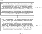
- the coding device determines the motion vector difference of the affine picture block according to the determined control points, determines the motion vector precision of the affine picture block, determines the size of the affine motion compensation picture subblock in the affine picture block according to the determined motion vector difference, the determined motion vector precision, and the distance between the control points, and performs coding processing on the affine picture block according to the determined size.
- the coding device determines the size of the affine motion compensation picture subblock according to the determined motion vector difference of the affine picture block, the determined motion vector precision, and the distance between the control points, and performs coding processing on the affine picture block according to the size of the affine motion compensation picture subblock.
- a picture subblock of an appropriate size is selected in a coding process, so that coding complexity can be reduced, and coding efficiency can be improved.
- the affine (Affine) picture block is a picture block in which motion vectors of all units comply with same affine models, for example, a same affine model which may be indicated by same parameters, for example, a same group of parameters.
- the unit is a group of pixels, for example, may be a pixel, or may be a block structure such as 1x3 or 2x4. This is not limited in the present invention.
- the affine motion compensation (Affine Motion Compensation, "Affine-MC" for short) picture subblock is a picture subblock that is obtained by dividing the affine block and used for performing motion compensation prediction, and affine-MC blocks may have a same size or different sizes. This is not limited in the present invention.
- any non-overlapping pixels may be selected as control points to determine the motion vector difference of the affine block. This is not limited in the present invention.
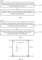
- S1100 includes the following steps:
- S1102. Determine a second component of the motion vector difference according to a difference between motion vectors of a third control point and a fourth control point that are located on a same vertical line.
- a first horizontal distance exists between the first control point and the second control point, and a first vertical distance exists between the third control point and the fourth control point.
- the first component of the motion vector difference is a horizontal component of the motion vector difference
- the second component of the motion vector difference is a vertical component of the motion vector difference
- first, second, third, and fourth are only intended to distinguish between pixels and shall not be construed as any limitation to the protection scope of the present invention.
- the first control point may also be referred to as the second control point, and the second control point may become the first control point.
- the first control point and the third control point are the same pixel. That is, a quantity of selected control points is three, and one of the three control points is located on a same horizontal line as one of the other two control points, and is located on a same vertical line as the other one of the two control points.
- the first control point, the second control point, the third control point, and the fourth control point are vertices of the affine block. Assuming that four vertices of one affine block are marked as a vertex in an upper left corner, a vertex in a lower left corner, a vertex in an upper right corner, and a vertex in a lower right corner respectively, any three vertices located in two orthogonal directions may be selected to determine a motion vector difference of the affine block.
- the vertex in the upper left corner, the vertex in the lower left corner, and the vertex in the upper right corner may be selected, or the vertex in the upper left corner, the vertex in the upper right corner, and the vertex in the lower right corner may be selected. This is not limited in the present invention.
- a difference between components in either direction, in components in two directions of the motion vectors of the first control point and the second control point may be determined as the first component of the motion vector difference of the affine block, and a difference between components in either direction, in components in two directions of the motion vectors of the third control point and the fourth control point may be determined as the second component of the motion vector difference of the affine block; or according to actual requirements for coding complexity and coding efficiency, a numeric value between two differences of components in two directions of the motion vectors of the first control point and the second control point may be selected and determined as the first component, and a numeric value between two differences of components in two directions of the motion vectors of the third control point and the fourth control point may be selected and determined as the second component.
- S1101 specifically includes the following steps:
- S1102 specifically includes the following steps:
- an affine transformation parameter of a pixel in the affine picture block may be determined, and pixels in the affine picture block have the same affine transformation parameter.
- S1103 is specifically: determining the first horizontal component difference and the first vertical component difference according to the affine transformation parameter and the first horizontal distance.
- S1105 is specifically: determining the second horizontal component difference and the second vertical component difference according to the affine transformation parameter and the first vertical distance.
- sequence numbers of the foregoing processes do not mean execution sequences.
- the execution sequences of the processes should be determined according to functions and internal logic of the processes, and should not be construed as any limitation to the implementation processes of the embodiments of the present invention.
- an affine transformation model may be a 6-parameter affine transformation model in the prior art, or may be a 4-parameter or 2-parameter affine transformation model.
- 6-parameter affine transformation model it is assumed that ( x, y ) are coordinates of a pixel P in a current picture, and ( x', y' ) are coordinates of a pixel P' that is in a reference picture and matches the pixel P , and a, b, c, d, e, and f are affine transformation parameters.
- a position ( x', y' ) of the pixel (x ,y ) in the reference picture may be obtained, and therefore, a prediction signal of the pixel may be obtained from the reference picture:
- the first component and the second component of the motion vector difference of the affine block may be determined.
- the affine transformation parameter may be obtained by computing each coefficient iteratively, for example, adding 1 to the coefficient a to determine whether a motion compensation prediction signal in the model is optimal.
- the affine transformation parameter may be obtained through derivation according to an affine transformation coefficient of an adjacent affine block.
- the present invention is not limited thereto.
- a motion vector of the first control point, a motion vector of the second control point, a motion vector of the third control point, and a motion vector of the fourth control point may be determined.
- S1103 is specifically: determining a difference between a horizontal component of the motion vector of the first control point and a horizontal component of the motion vector of the second control point as the first horizontal component difference; and determining a difference between a vertical component of the motion vector of the first control point and a vertical component of the motion vector of the second control point as the first vertical component difference.
- S1105 is specifically: determining a difference between a horizontal component of the motion vector of the third control point and a horizontal component of the motion vector of the fourth control point as the second horizontal component difference; and determining a difference between a vertical component of the motion vector of the third control point and a vertical component of the motion vector of the fourth control point as the second vertical component difference.
- the motion vectors of the control points may be directly determined.
- the first component and the second component of the motion vector difference of the affine block may be directly obtained.
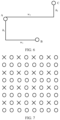
- FIG. 5 is a schematic diagram of an affine picture block and control points according to an embodiment of the present invention.
- Two control points A and B are on a same horizontal line, and have a distance w .
- Two control points C and D are on a same vertical line, and have a distance h.
- control points A and C may be the same pixel.
- control points A, B, C, and D may be vertices of the affine block.
- a distance between the control points A and B is a width W of the affine block
- a distance between the control points C and D is a height H of the affine block.
- the first control point and the second control point are two adjacent pixels
- the third control point and the fourth control point are two adjacent pixels
- S1103 and S1105 are specifically: determining a motion vector of a first pixel, a motion vector of a second pixel, and a motion vector of a third pixel, where the first pixel, the second pixel, and the third pixel are non-overlapping pixels; determining a second horizontal distance and a second vertical distance between the first pixel and the second pixel; determining a third horizontal distance and a third vertical distance between the first pixel and the third pixel; and determining the first horizontal component difference, the first vertical component difference, the second horizontal component difference, and the second vertical component difference according to the motion vector of the first pixel, the motion vector of the second pixel, the motion vector of the third pixel, the second horizontal distance, the second vertical distance, the third horizontal distance, and the third vertical distance.
- positions of the three pixels are shown in FIG. 6 , and motion vectors of the three pixels are ( vx A , vy A ) , ( vx B , vy B ), and ( vx C , vy C ) respectively.
- a distance between the pixel A and the pixel B in a horizontal direction is w 1
- a distance in a vertical direction is h 1
- a distance between the pixel A and the pixel C in the horizontal direction is w 2
- a distance in the vertical direction is h 2 .
- a distance between the pixel B and the pixel C in the horizontal direction is w 2 - w 1
- a distance in the vertical direction is h 1 + h 2 .
- horizontal component differences of motion vectors of two adjacent pixels in the horizontal direction are ⁇ mvx hor and ⁇ mvy hor respectively
- vertical component differences of motion vectors of two adjacent pixels in the vertical direction are ⁇ mvx ver and ⁇ mvy ver respectively. Because motion vectors in the picture block change linearly, ⁇ mvx hor , ⁇ mvy hor , ⁇ mvx ver , and ⁇ mvy ver may be determined by determining motion vectors of the pixels A, B, and C.
- motion vector differences of adjacent pixels in the picture block may be determined, and specifically, may be determined according to formulas (13) to (16):
- vx B vx A + w 1 ⁇ ⁇ mvx hor + h 1 ⁇ ⁇ mvx ver
- vy B vy A + w 1 ⁇ ⁇ mvy hor + h 1 ⁇ ⁇ mvy ver
- vx C vx A + w 2 ⁇ ⁇ mvx hor + h 2 ⁇ ⁇ mvx ver
- vy C vy A + w 2 ⁇ ⁇ mvy hor + h 2 ⁇ ⁇ mvy ver or may be determined according to formulas (13) and (14) and formulas (17) and (18):
- vx C vx B + w 2 ⁇ w 1 ⁇ ⁇ mvx hor + h 2 + h 1 ⁇ ⁇ mvx ver vy
- the coding device may obtain motion vectors of all control points by performing a motion estimation search; may obtain motion vectors of all control points from adjacent picture blocks; may compute motion vectors of all control points according to the affine transformation model; may obtain motion vectors of some control points by performing a motion estimation search, and obtain motion vectors of other control points from adjacent picture blocks; may obtain motion vectors of some control points by performing an affine motion estimation search, and obtain motion vectors of other control points through computation according to the affine transformation model; or may obtain motion vectors of some control points from adjacent picture blocks, and compute motion vectors of other control points according to the affine transformation model.
- the present invention is not limited thereto.
- a third preset value may be determined as the motion vector precision of the affine picture block; or the motion vector precision of the affine picture block may be determined according to a feature of a picture block adjacent to the affine picture block, where the adjacent picture block is a picture block spatially and/or temporally adjacent to the affine picture block.
- a value of a motion vector of the affine block may be an integer.
- the motion vector is of integer-pixel precision, that is, the pixel precision is 1.
- a value of a motion vector may not be an integer.
- the motion vector is of sub-pixel precision, including precision such as 1/2, 1/4, or 1/8.
- FIG. 7 shows a 4x4 picture block, where ⁇ indicates a pixel in an integer-pixel position, and a captured picture has only pixels in integer-pixel positions. O indicates a pixel in a 1/2 precision position, and needs to be obtained by interpolating a pixel in an integer-pixel position.
- Values of pixels in other precision positions need to be obtained by further interpolating pixels in integer-pixel precision positions or pixels in 1/2 precision positions. If a motion vector of a current pixel is an integer, the motion vector points to a position of ⁇ in the reference picture. If the motion vector of the current pixel is of 1/2 precision, the motion vector points to a position of O in the reference picture.
- the motion vector precision of the affine block is highest precision of motion vectors of all pixels in the affine block.
- the motion vector precision of the affine block may be preset, for example, integer-pixel precision, or precision such as 1/2, 1/4, 1/8, or 1/16.
- the motion vector precision may be determined according to a feature of a picture block adjacent to the affine picture block. For example, if an adjacent picture is relatively smooth, it may be predicted that the current affine block is also relatively smooth. Therefore, higher motion vector precision such as 1/8 or 1/16 precision may be selected. Otherwise, lower motion vector precision such as integer-pixel precision or 1/2 precision may be selected.
- the obtained precision is indicated by MvAc.
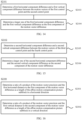
- S1300 specifically includes the following steps:
- S1302. Determine a ratio of a product of the motion vector precision and the first vertical distance to the second component of the motion vector difference as a length of the affine motion compensation picture subblock in a vertical direction.
- the affine block is divided into multiple affine-MC blocks according to previously obtained expected motion vector precision MvAc to ensure that motion vector precision of each affine-MC block reaches MvAc.
- a width of the affine-MC block is aMcW and that a height of the affine-MC block is aMcH, aMcW and aMcH
- the horizontal distance between the first control point and the second control point is the width W of the affine block
- the vertical distance between the third control point and the fourth control point is the height H of the affine block.
- the first horizontal distance between the first control point and the second control point is 1, that is, the first control point is separated from the second control point by an integer quantity of pixels; the first vertical distance between the third control point and the fourth control point is 1, that is, the third control point is separated from the fourth control point by an integer quantity of pixels.
- the coding device determines the size of the affine motion compensation picture subblock according to the determined motion vector difference of the affine picture block, the determined motion vector precision, and the distance between the control points, and performs coding processing on the affine picture block according to the size of the affine motion compensation picture subblock.
- a picture subblock of an appropriate size is selected in the coding process, so that coding complexity can be reduced and coding efficiency can be improved, while motion compensation prediction efficiency in affine transformation is maintained.
- S1300 includes the following steps.
- a lower limit may be set for the width and the height of the affine-MC block.
- the preset lower limit is determined as the width or the height of the affine-MC block.
- the lower limit may be set to 4, but may also be set to another numeric value according to an actual requirement.
- a lower limit of the width may be set to 2, and a specified value of the height is set to 3; or a lower limit of the width is set to 1, and a specified value of the height is set to 2. This is not limited in the present invention.
- S1400 includes the following steps:
- each affine-MC block may include multiple pixels, and a motion vector of a pixel needs to be selected from each affine-MC as a motion vector of the affine-MC block.
- a motion vector of a pixel in a central position of the affine-MC block may be selected as the motion vector of the affine-MC block; an average value of motion vectors of all pixels in the affine-MC block may be used as the motion vector of the affine-MC block; or a motion vector of a pixel in an upper left corner of the affine-MC block may be selected as the motion vector of the affine-MC block.
- the present invention is not limited thereto.
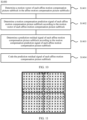
- signals of boundary pixels of each affine motion compensation picture subblock are filtered, and the boundary pixels are pixels in one or more rows at a boundary of each affine motion compensation picture subblock.
- the signal of the boundary pixel includes a motion compensation prediction signal and/or a reconstructed signal
- the reconstructed signal is a sum of the motion compensation prediction signal and a reconstructed residual signal
- a thick solid line block indicates an affine block
- a thin solid line block indicates an affine-MC block
- a dashed line block indicates pixels at boundaries of adjacent affine-MC blocks
- a cross indicates a pixel.
- a region of a dashed line block in FIG. 11 includes pixels of adjacent affine-MC blocks in two rows or two columns at boundaries of the affine-MC blocks, or may include one row or one column, or three rows or three columns at the boundaries of the affine-MC blocks. Because motion vectors of adjacent affine-MC blocks may be different, prediction signals obtained from the reference picture are not adjacent in the reference picture. This causes discontinuity of prediction signals at the boundaries of the adjacent affine-MC blocks, and therefore causes discontinuity of residuals, and affects coding efficiency of the residuals. Therefore, filtering the motion compensation prediction signals at the boundaries of the affine-MC blocks is considered.
- a reconstructed signal is generally obtained by adding a reconstructed residual signal to a motion compensation prediction signal.
- lossy coding is used for the residual signal. This causes distortion between the reconstructed residual signal and an original residual signal. Distortion directions of pixels at the boundaries of adjacent affine-MC blocks may be inconsistent. For example, a right pixel of a first affine-MC block becomes larger due to distortion, and a left pixel of a right adjacent affine-MC block becomes smaller due to distortion. This causes discontinuity of pixel values at boundaries of reconstructed pixels of the affine-MC blocks, and impairs subjective and objective effects. Therefore, the reconstructed signals need to be filtered.
- filtering may be performing by using a lowpass filter, so that pixel values in the boundary region change more smoothly.
- filtering is performed by using a Gauss filter.
- the present invention is not limited thereto.
- an LDP test structure is used to test coding complexity and coding efficiency when the method in this embodiment of the present invention and the method in the prior art are used to perform coding.
- a result is shown in Table 1.
- Table 1 Class Sequence The method in the present invention relative to the method in the prior art LDP Tractor -0.2% BlueSky 0.0% SpinCalendar 0.0% Jets -0.5% Enct 86% Dect 78%
- the coding device determines the size of the affine motion compensation picture subblock according to the determined motion vector difference of the affine picture block, the determined motion vector precision, and the distance between the control points, and performs coding processing on the affine picture block according to the size of the affine motion compensation picture subblock.
- a picture subblock of an appropriate size is selected in the coding process, so that coding complexity can be reduced, and coding efficiency can be improved.
- the video picture coding method according to this embodiment of the present invention is hereinbefore described in detail with reference to FIG. 1 to FIG. 11 .
- a video picture decoding method according to an embodiment of the present invention is hereinafter described in detail with reference to FIG. 12 to FIG. 18 . It should be noted that, related operations of a decoder are essentially consistent with those of an encoder. To avoid repetition, details are not described again herein.
- FIG. 12 shows a schematic flowchart of a video picture decoding method according to an embodiment of the present invention.
- the method shown in FIG. 12 may be performed by a decoding device, for example, a decoder.
- the method 2000 includes the following steps.
- the decoding device determines the motion vector difference of the affine picture block according to the determined control points, determines the motion vector precision of the affine picture block, determines the size of the affine motion compensation picture subblock in the affine picture block according to the determined motion vector difference, the determined motion vector precision, and the distance between the control points, and performs decoding processing on the affine picture block according to the determined size.
- the decoding device determines the size of the affine motion compensation picture subblock according to the determined motion vector difference of the affine picture block, the determined motion vector precision, and the distance between the control points, and performs decoding processing on the affine picture block according to the determined size. In this way, a picture subblock of an appropriate size is selected in a decoding process, so that decoding complexity can be reduced, and decoding efficiency can be improved.
- S2100 includes the following steps:
- a first horizontal distance exists between the first control point and the second control point, and a first vertical distance exists between the third control point and the fourth control point.
- the first component of the motion vector difference is a horizontal component of the motion vector difference
- the second component of the motion vector difference is a vertical component of the motion vector difference
- S2101 specifically includes the following steps:
- S2102 specifically includes the following steps:
- S2103 is specifically: determining the first horizontal component difference and the first vertical component difference according to the affine transformation parameter and the first horizontal distance.
- S2105 is specifically: determining the second horizontal component difference and the second vertical component difference according to the affine transformation parameter and the first vertical distance.
- a motion vector of the first control point, a motion vector of the second control point, a motion vector of the third control point, and a motion vector of the fourth control point may be determined.
- S2103 is specifically: determining a difference between a horizontal component of the motion vector of the first control point and a horizontal component of the motion vector of the second control point as the first horizontal component difference; and determining a difference between a vertical component of the motion vector of the first control point and a vertical component of the motion vector of the second control point as the first vertical component difference.
- S2105 is specifically: determining a difference between a horizontal component of the motion vector of the third control point and a horizontal component of the motion vector of the fourth control point as the second horizontal component difference; and determining a difference between a vertical component of the motion vector of the third control point and a vertical component of the motion vector of the fourth control point as the second vertical component difference.
- the first control point and the second control point are two adjacent pixels
- the third control point and the fourth control point are two adjacent pixels
- S2103 and S2105 are specifically: determining a motion vector of a first pixel, a motion vector of a second pixel, and a motion vector of a third pixel, where the first pixel, the second pixel, and the third pixel are non-overlapping pixels; determining a second horizontal distance and a second vertical distance between the first pixel and the second pixel; determining a third horizontal distance and a third vertical distance between the first pixel and the third pixel; and determining the first horizontal component difference, the first vertical component difference, the second horizontal component difference, and the second vertical component difference according to the motion vector of the first pixel, the motion vector of the second pixel, the motion vector of the third pixel, the second horizontal distance, the second vertical distance, the third horizontal distance, and the third vertical distance.
- the decoding device may obtain motion vectors of all control points by parsing a bit stream; may obtain motion vectors of all control points from adjacent picture blocks; may compute motion vectors of all control points according to an affine transformation model; may obtain motion vectors of some control points by parsing a bit stream, and obtain motion vectors of other control points from adjacent picture blocks; may obtain motion vectors of some control points by parsing a bit stream, and obtain motion vectors of other control points through computation according to an affine transformation model; or may obtain motion vectors of some control points from adjacent picture blocks, and compute motion vectors of other control points according to an affine transformation model.
- the present invention is not limited thereto.
- a third preset value may be determined as the motion vector precision of the affine picture block; or the motion vector precision of the affine picture block is determined according to a feature of a picture block adjacent to the affine picture block, where the adjacent picture block is a picture block spatially and/or temporally adjacent to the affine picture block.
- S2300 specifically includes the following steps:
- S2300 includes the following steps:
- S2400 includes the following steps:
- signals of boundary pixels of each affine motion compensation picture subblock are filtered, and the boundary pixels are pixels in one or more rows at a boundary of each affine motion compensation picture subblock.
- the signal of the boundary pixel includes a motion compensation prediction signal and/or a reconstructed signal
- the reconstructed signal is a sum of the motion compensation prediction signal and a reconstructed residual signal. Therefore, in the video picture decoding method according to this embodiment of the present invention, the decoding device determines the size of the affine motion compensation picture subblock according to the determined motion vector difference of the affine picture block, the motion vector precision, and the distance between the control points, and performs decoding processing on the affine picture block according to the determined size. In this way, a picture subblock of an appropriate size is selected in the decoding process, so that decoding complexity can be reduced, and decoding efficiency can be improved.
- the decoding method in the present invention may also be:
- the decoding method may be:
- the decoder may directly use a parameter sent by an encoder to the decoder to determine the size of the affine motion compensation picture subblock without re-computation, and further reduce computational complexity.
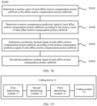
- the coding device 10 includes:
- the coding device determines the motion vector difference of the affine picture block according to the determined control points, determines the motion vector precision of the affine picture block, determines the size of the affine motion compensation picture subblock in the affine picture block according to the determined motion vector difference, the determined motion vector precision, and the distance between the control points, and performs coding processing on the affine picture block according to the determined size.
- the coding device determines the size of the affine motion compensation picture subblock according to the determined motion vector difference of the affine picture block, the determined motion vector precision, and the distance between the control points, and performs coding processing on the affine picture block according to the size of the affine motion compensation picture subblock.
- a picture subblock of an appropriate size is selected in a coding process, so that coding complexity can be reduced, and coding efficiency can be improved.
- the first determining module 11 is specifically configured to: determine a first component of the motion vector difference according to a difference between motion vectors of a first control point and a second control point that are located on a same horizontal line; and determine a second component of the motion vector difference according to a difference between motion vectors of a third control point and a fourth control point that are located on a same vertical line; where a first horizontal distance exists between the first control point and the second control point, and a first vertical distance exists between the third control point and the fourth control point.
- the first determining module 11 is specifically configured to: determine a first horizontal component difference and a first vertical component difference between the motion vectors of the first control point and the second control point; determine a larger one of the first horizontal component difference and the first vertical component difference as the first component of the motion vector difference; determine a second horizontal component difference and a second vertical component difference between the motion vectors of the third control point and the fourth control point; and determine a larger one of the second horizontal component difference and the second vertical component difference as the second component of the motion vector difference.
- the first determining module 11 is specifically configured to: determine an affine transformation parameter of a pixel in the affine picture block, where pixels in the affine picture block have the same affine transformation parameter; determine the first horizontal component difference and the first vertical component difference according to the affine transformation parameter and the first horizontal distance; and determine the second horizontal component difference and the second vertical component difference according to the affine transformation parameter and the first vertical distance.
- the first determining module 11 is specifically configured to: determine a motion vector of the first control point, a motion vector of the second control point, a motion vector of the third control point, and a motion vector of the fourth control point; determine a difference between a horizontal component of the motion vector of the first control point and a horizontal component of the motion vector of the second control point as the first horizontal component difference; determine a difference between a vertical component of the motion vector of the first control point and a vertical component of the motion vector of the second control point as the first vertical component difference; determine a difference between a horizontal component of the motion vector of the third control point and a horizontal component of the motion vector of the fourth control point as the second horizontal component difference; and determine a difference between a vertical component of the motion vector of the third control point and a vertical component of the motion vector of the fourth control point as the second vertical component difference.
- the first control point and the second control point are two adjacent pixels
- the third control point and the fourth control point are two adjacent pixels
- the first determining module 11 is specifically configured to: determine a motion vector of a first pixel, a motion vector of a second pixel, and a motion vector of a third pixel, where the first pixel, the second pixel, and the third pixel are non-overlapping pixels; determine a second horizontal distance and a second vertical distance between the first pixel and the second pixel; determine a third horizontal distance and a third vertical distance between the first pixel and the third pixel; and determine the first horizontal component difference, the first vertical component difference, the second horizontal component difference, and the second vertical component difference according to the motion vector of the first pixel, the motion vector of the second pixel, the motion vector of the third pixel, the second horizontal distance, the second vertical distance, the third horizontal distance, and the third vertical distance.
- the third determining module 13 is specifically configured to: determine a ratio of a product of the motion vector precision and the first horizontal distance to the first component of the motion vector difference as a length of the affine motion compensation picture subblock in a horizontal direction; and determine a ratio of a product of the motion vector precision and the first vertical distance to the second component of the motion vector difference as a length of the affine motion compensation picture subblock in a vertical direction.
- the third determining module 13 is specifically configured to:
- the first control point and the third control point are the same pixel.
- the first control point, the second control point, the third control point, and the fourth control point are vertices of the affine picture block.
- the first preset value is 4, and/or the second preset value is 4.
- the second determining module 12 is specifically configured to: determine a third preset value as the motion vector precision of the affine picture block; or determine the motion vector precision of the affine picture block according to a feature of a picture block adjacent to the affine picture block, where the adjacent picture block is a picture block spatially and/or temporally adjacent to the affine picture block.
- the coding module 14 is specifically configured to: determine a motion vector of each affine motion compensation picture subblock in the affine motion compensation picture subblocks; determine a motion compensation prediction signal of each affine motion compensation picture subblock according to the motion vector of each affine motion compensation picture subblock; determine a prediction residual signal of each affine motion compensation picture subblock according to the motion compensation prediction signal of each affine motion compensation picture subblock; and code the prediction residual signal of each affine motion compensation picture subblock.
- the coding device 10 further includes: a filtering module 15, configured to filter signals of boundary pixels of each affine motion compensation picture subblock, where the boundary pixels are pixels in one or more rows at a boundary of each affine motion compensation picture subblock.
- the signal of the boundary pixel includes a motion compensation prediction signal and/or a reconstructed signal
- the reconstructed signal is a sum of the motion compensation prediction signal and a reconstructed residual signal
- the coding device 10 may correspondingly perform the video picture coding method 1000 in the embodiments of the present invention, and the foregoing and other operations and/or functions of the modules in the coding device 10 are separately intended to implement the corresponding procedures of the method in FIG. 1 to FIG. 11 .
- the foregoing and other operations and/or functions of the modules in the coding device 10 are separately intended to implement the corresponding procedures of the method in FIG. 1 to FIG. 11 .
- details are not described again herein.
- the coding device determines the size of the affine motion compensation picture subblock according to the determined motion vector difference of the affine picture block, the determined motion vector precision, and the distance between the control points, and performs coding processing on the affine picture block according to the size. In this way, a picture subblock of an appropriate size is selected in the coding process, so that coding complexity can be reduced, and coding efficiency can be improved.
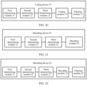
- the decoding device 20 includes:
- the decoding device determines the motion vector difference of the affine picture block according to the determined control points, determines the motion vector precision of the affine picture block, determines the size of the affine motion compensation picture subblock in the affine picture block according to the determined motion vector difference, the determined motion vector precision, and the distance between the control points, and performs decoding processing on the affine picture block according to the determined size.
- the decoding device determines the size of the affine motion compensation picture subblock according to the determined motion vector difference of the affine picture block, the determined motion vector precision, and the distance between the control points, and performs decoding processing on the affine picture block according to the size of the affine motion compensation picture subblock. In this way, a picture subblock of an appropriate size is selected in a decoding process, so that decoding complexity can be reduced, and decoding efficiency can be improved.
- the first determining module 21 is specifically configured to: determine a first component of the motion vector difference according to a difference between motion vectors of a first control point and a second control point that are located on a same horizontal line; and determine a second component of the motion vector difference according to a difference between motion vectors of a third control point and a fourth control point that are located on a same vertical line; where a first horizontal distance exists between the first control point and the second control point, and a first vertical distance exists between the third control point and the fourth control point.
- the first determining module 21 is specifically configured to: determine a first horizontal component difference and a first vertical component difference between the motion vectors of the first control point and the second control point; determine a larger one of the first horizontal component difference and the first vertical component difference as the first component of the motion vector difference; determine a second horizontal component difference and a second vertical component difference between the motion vectors of the third control point and the fourth control point; and determine a larger one of the second horizontal component difference and the second vertical component difference as the second component of the motion vector difference.
- the first determining module 21 is specifically configured to: determine an affine transformation parameter of a pixel in the affine picture block, where pixels in the affine picture block have the same affine transformation parameter; determine the first horizontal component difference and the first vertical component difference according to the affine transformation parameter and the first horizontal distance; and determine the second horizontal component difference and the second vertical component difference according to the affine transformation parameter and the first vertical distance.
- the first determining module 21 is specifically configured to: determine a motion vector of the first control point, a motion vector of the second control point, a motion vector of the third control point, and a motion vector of the fourth control point; determine a difference between a horizontal component of the motion vector of the first control point and a horizontal component of the motion vector of the second control point as the first horizontal component difference; determine a difference between a vertical component of the motion vector of the first control point and a vertical component of the motion vector of the second control point as the first vertical component difference; determine a difference between a horizontal component of the motion vector of the third control point and a horizontal component of the motion vector of the fourth control point as the second horizontal component difference; and determine a difference between a vertical component of the motion vector of the third control point and a vertical component of the motion vector of the fourth control point as the second vertical component difference.
- the first determining module 21 is specifically configured to: determine a motion vector of a first pixel, a motion vector of a second pixel, and a motion vector of a third pixel, where the first pixel, the second pixel, and the third pixel are non-overlapping pixels; determine a second horizontal distance and a second vertical distance between the first pixel and the second pixel; determine a third horizontal distance and a third vertical distance between the first pixel and the third pixel; and determine the first horizontal component difference, the first vertical component difference, the second horizontal component difference, and the second vertical component difference according to the motion vector of the first pixel, the motion vector of the second pixel, the motion vector of the third pixel, the second horizontal distance, the second vertical distance, the third horizontal distance, and the third vertical distance.
- the third determining module 23 is specifically configured to: determine a ratio of a product of the motion vector precision and the first horizontal distance to the first component of the motion vector difference as a length of the affine motion compensation picture subblock in a horizontal direction; and determine a ratio of a product of the motion vector precision and the first vertical distance to the second component of the motion vector difference as a length of the affine motion compensation picture subblock in a vertical direction.
- the third determining module 23 is specifically configured to:
- the first control point and the third control point are the same pixel.
- the first control point, the second control point, the third control point, and the fourth control point are vertices of the affine picture block.
- the first preset value is 4, and/or the second preset value is 4.
- the second determining module 22 is specifically configured to: determine a third preset value as the motion vector precision of the affine picture block; or determine the motion vector precision of the affine picture block according to a feature of a picture block adjacent to the affine picture block, where the adjacent picture block is a picture block spatially and/or temporally adjacent to the affine picture block.
- the decoding module 24 is specifically configured to: determine a motion vector of each affine motion compensation picture subblock in the affine motion compensation picture subblocks; determine a motion compensation prediction signal of each affine motion compensation picture subblock according to the motion vector of each affine motion compensation picture subblock; determine a prediction residual signal of each affine motion compensation picture subblock according to the motion compensation prediction signal of each affine motion compensation picture subblock; and decode the prediction residual signal of each affine motion compensation picture subblock.
- the decoding device 20 further includes: a filtering module 25, configured to filter signals of boundary pixels of each affine motion compensation picture subblock, where the boundary pixels are pixels in one or more rows at a boundary of each affine motion compensation picture subblock.
- the signal of the boundary pixel includes a motion compensation prediction signal and/or a reconstructed signal
- the reconstructed signal is a sum of the motion compensation prediction signal and a reconstructed residual signal
- the decoding device 20 may correspondingly perform the video picture decoding method 2000 in the embodiments of the present invention, and the foregoing and other operations and/or functions of the modules in the decoding device 20 are separately intended to implement the corresponding procedures of the method in FIG. 12 to FIG. 18 .
- the decoding device 20 may correspondingly perform the video picture decoding method 2000 in the embodiments of the present invention, and the foregoing and other operations and/or functions of the modules in the decoding device 20 are separately intended to implement the corresponding procedures of the method in FIG. 12 to FIG. 18 .
- details are not described again herein.
- the decoding device determines the size of the affine motion compensation picture subblock according to the determined motion vector difference of the affine picture block, the determined motion vector precision, and the distance between the control points, and performs decoding processing on the affine picture block according to the size. In this way, a picture subblock of an appropriate size is selected in the decoding process, so that decoding complexity can be reduced, and decoding efficiency can be improved.
- an embodiment of the present invention further provides a coding device 30, including a processor 31, a memory 32, and a bus system 33.
- the processor 31 and the memory 32 are connected by the bus system 33.
- the memory 32 is configured to store an instruction.
- the processor 31 is configured to execute the instruction stored in the memory 32.
- the memory 32 of the coding device 30 stores program code, and the processor 31 may invoke the program code stored in the memory 32 to perform the following operations: determining a motion vector difference of an affine picture block; determining motion vector precision of the affine picture block; determining a size of an affine motion compensation picture subblock in the affine picture block according to the motion vector difference, the motion vector precision, and a distance between control points in the affine picture block, where the control points are pixels used to determine the motion vector difference; and performing coding processing on the affine picture block according to the size of the affine motion compensation picture subblock.
- the coding device determines the size of the affine motion compensation picture subblock according to the determined motion vector difference of the affine picture block, the determined motion vector precision, and the distance between the control points, and performs coding processing on the affine picture block according to the size of the affine motion compensation picture subblock.
- a picture subblock of an appropriate size is selected in a coding process, so that coding complexity can be reduced, and coding efficiency can be improved.
- the processor 31 may be a central processing unit (Central Processing Unit, "CPU” for short), or the processor 31 may be another general purpose processor, a digital signal processor (DSP), an application-specific integrated circuit (ASIC), a field programmable gate array (FPGA), or another programmable logic device, discrete gate or transistor logic device, discrete hardware component, or the like.
- the general purpose processor may be a microprocessor, or the processor may be any conventional processor, or the like.
- the memory 32 may include a read-only memory and a random access memory, and provide an instruction and data to the processor 31.
- a part of the memory 32 may further include a non-volatile random access memory.
- the memory 32 may further store information about a device type.
- the bus system 33 may further include a power bus, a control bus, a status signal bus, and the like, in addition to a data bus. However, for clear description, various buses in the figure are marked as the bus system 33.
- each step of the foregoing method may be completed by using an integrated logic circuit of hardware in the processor 31 or an instruction in a form of software.
- the steps of the method disclosed with reference to the embodiments of the present invention may be directly performed by a hardware processor, or may be performed by using a combination of hardware in the processor and a software module.
- the software module may be located in a mature storage medium in the art, such as a random access memory, a flash memory, a read-only memory, a programmable read-only memory, an electrically erasable programmable memory, or a register.
- the storage medium is located in the memory 32.
- the processor 31 reads information in the memory 32 and completes the steps in the foregoing method in combination with the hardware of the processor 31. To avoid repetition, details are not described again herein.
- the processor 31 is specifically configured to: determine a first component of the motion vector difference according to a difference between motion vectors of a first control point and a second control point that are located on a same horizontal line; and determine a second component of the motion vector difference according to a difference between motion vectors of a third control point and a fourth control point that are located on a same vertical line; where a first horizontal distance exists between the first control point and the second control point, and a first vertical distance exists between the third control point and the fourth control point.
- the processor 31 is specifically configured to: determine a first horizontal component difference and a first vertical component difference between the motion vectors of the first control point and the second control point; determine a larger one of the first horizontal component difference and the first vertical component difference as the first component of the motion vector difference; determine a second horizontal component difference and a second vertical component difference between the motion vectors of the third control point and the fourth control point; and determine a larger one of the second horizontal component difference and the second vertical component difference as the second component of the motion vector difference.
- the processor 31 is specifically configured to: determine an affine transformation parameter of a pixel in the affine picture block, where pixels in the affine picture block have the same affine transformation parameter; determine the first horizontal component difference and the first vertical component difference according to the affine transformation parameter and the first horizontal distance; and determine the second horizontal component difference and the second vertical component difference according to the affine transformation parameter and the first vertical distance.
- the processor 31 is specifically configured to: determine a motion vector of the first control point, a motion vector of the second control point, a motion vector of the third control point, and a motion vector of the fourth control point; determine a difference between a horizontal component of the motion vector of the first control point and a horizontal component of the motion vector of the second control point as the first horizontal component difference; determine a difference between a vertical component of the motion vector of the first control point and a vertical component of the motion vector of the second control point as the first vertical component difference; determine a difference between a horizontal component of the motion vector of the third control point and a horizontal component of the motion vector of the fourth control point as the second horizontal component difference; and determine a difference between a vertical component of the motion vector of the third control point and a vertical component of the motion vector of the fourth control point as the second vertical component difference.
- the first control point and the second control point are two adjacent pixels
- the third control point and the fourth control point are two adjacent pixels
- the processor 31 is specifically configured to: determine a motion vector of a first pixel, a motion vector of a second pixel, and a motion vector of a third pixel, where the first pixel, the second pixel, and the third pixel are non-overlapping pixels; determine a second horizontal distance and a second vertical distance between the first pixel and the second pixel; determine a third horizontal distance and a third vertical distance between the first pixel and the third pixel; and determine the first horizontal component difference, the first vertical component difference, the second horizontal component difference, and the second vertical component difference according to the motion vector of the first pixel, the motion vector of the second pixel, the motion vector of the third pixel, the second horizontal distance, the second vertical distance, the third horizontal distance, and the third vertical distance.
- the processor 31 is specifically configured to: determine a ratio of a product of the motion vector precision and the first horizontal distance to the first component of the motion vector difference as a length of the affine motion compensation picture subblock in a horizontal direction; and determine a ratio of a product of the motion vector precision and the first vertical distance to the second component of the motion vector difference as a length of the affine motion compensation picture subblock in a vertical direction.
- the processor 31 is specifically configured to:
- the first control point and the third control point are the same pixel.
- the first control point, the second control point, the third control point, and the fourth control point are vertices of the affine picture block.
- the first preset value is 4, and/or the second preset value is 4.
- the processor 31 is specifically configured to: determine a third preset value as the motion vector precision of the affine picture block; or determine the motion vector precision of the affine picture block according to a feature of a picture block adjacent to the affine picture block, where the adjacent picture block is a picture block spatially and/or temporally adjacent to the affine picture block.
- the processor 31 is specifically configured to: determine a motion vector of each affine motion compensation picture subblock in the affine motion compensation picture subblocks; determine a motion compensation prediction signal of each affine motion compensation picture subblock according to the motion vector of each affine motion compensation picture subblock; determine a prediction residual signal of each affine motion compensation picture subblock according to the motion compensation prediction signal of each affine motion compensation picture subblock; and code the prediction residual signal of each affine motion compensation picture subblock.
- the processor 31 is further configured to filter signals of boundary pixels of each affine motion compensation picture subblock, where the boundary pixels are pixels in one or more rows at a boundary of each affine motion compensation picture subblock.
- the signal of the boundary pixel includes a motion compensation prediction signal and/or a reconstructed signal
- the reconstructed signal is a sum of the motion compensation prediction signal and a reconstructed residual signal
- the coding device 30 may correspond to the coding device 10 in the embodiments of the present invention, and may correspond to a corresponding entity that performs the method 1000 according to the embodiments of the present invention, and the foregoing and other operations and/or functions of the modules in the coding device 30 are separately intended to implement the corresponding procedures of the method in FIG. 1 to FIG. 11 .
- details are not described again herein.
- the coding device determines the size of the affine motion compensation picture subblock according to the determined motion vector difference of the affine picture block, the determined motion vector precision, and the distance between the control points, and performs coding processing on the affine picture block according to the size of the affine motion compensation picture subblock. In this way, a picture subblock of an appropriate size is selected in the coding process, so that coding complexity can be reduced, and coding efficiency can be improved.
- an embodiment of the present invention further provides a decoding device 40, including a processor 41, a memory 42, and a bus system 43.
- the processor 41 and the memory 42 are connected by the bus system 43.
- the memory 42 is configured to store an instruction.
- the processor 41 is configured to execute the instruction stored in the memory 42.
- the memory 42 of the decoding device 40 stores program code, and the processor 41 may invoke the program code stored in the memory 42 to perform the following operations: determining a motion vector difference of an affine picture block; determining motion vector precision of the affine picture block; determining a size of an affine motion compensation picture subblock in the affine picture block according to the motion vector difference, the motion vector precision, and a distance between control points in the affine picture block, where the control points are pixels used to determine the motion vector difference; and performing decoding processing on the affine picture block according to the size of the affine motion compensation picture subblock.
- the decoding device determines the size of the affine motion compensation picture subblock according to the determined motion vector difference of the affine picture block, the determined motion vector precision, and the distance between the control points, and performs decoding processing on the affine picture block according to the size. In this way, a picture subblock of an appropriate size is selected in a decoding process, so that decoding complexity can be reduced, and decoding efficiency can be improved.
- the processor 41 may be a central processing unit (Central Processing Unit, "CPU” for short), or the processor 41 may be another general purpose processor, a digital signal processor (DSP), an application-specific integrated circuit (ASIC), a field programmable gate array (FPGA), or another programmable logic device, discrete gate or transistor logic device, discrete hardware component, or the like.
- the general purpose processor may be a microprocessor, or the processor may be any conventional processor, or the like.
- the memory 42 may include a read-only memory and a random access memory, and provide an instruction and data to the processor 41.
- a part of the memory 42 may further include a non-volatile random access memory.
- the memory 42 may further store information about a device type.
- the bus system 43 may further include a power bus, a control bus, a status signal bus, and the like, in addition to a data bus. However, for clear description, various buses in the figure are marked as the bus system 43.
- the processor 41 is specifically configured to: determine a first component of the motion vector difference according to a difference between motion vectors of a first control point and a second control point that are located on a same horizontal line; and determine a second component of the motion vector difference according to a difference between motion vectors of a third control point and a fourth control point that are located on a same vertical line; where a first horizontal distance exists between the first control point and the second control point, and a first vertical distance exists between the third control point and the fourth control point.
- the processor 41 is specifically configured to: determine a first horizontal component difference and a first vertical component difference between the motion vectors of the first control point and the second control point; determine a larger one of the first horizontal component difference and the first vertical component difference as the first component of the motion vector difference; determine a second horizontal component difference and a second vertical component difference between the motion vectors of the third control point and the fourth control point; and determine a larger one of the second horizontal component difference and the second vertical component difference as the second component of the motion vector difference.
- the processor 41 is specifically configured to: determine a motion vector of the first control point, a motion vector of the second control point, a motion vector of the third control point, and a motion vector of the fourth control point; determine a difference between a horizontal component of the motion vector of the first control point and a horizontal component of the motion vector of the second control point as the first horizontal component difference; determine a difference between a vertical component of the motion vector of the first control point and a vertical component of the motion vector of the second control point as the first vertical component difference; determine a difference between a horizontal component of the motion vector of the third control point and a horizontal component of the motion vector of the fourth control point as the second horizontal component difference; and determine a difference between a vertical component of the motion vector of the third control point and a vertical component of the motion vector of the fourth control point as the second vertical component difference.
- the first control point and the second control point are two adjacent pixels
- the third control point and the fourth control point are two adjacent pixels
- the processor 41 is specifically configured to: determine a motion vector of a first pixel, a motion vector of a second pixel, and a motion vector of a third pixel, where the first pixel, the second pixel, and the third pixel are non-overlapping pixels; determine a second horizontal distance and a second vertical distance between the first pixel and the second pixel; determine a third horizontal distance and a third vertical distance between the first pixel and the third pixel; and determine the first horizontal component difference, the first vertical component difference, the second horizontal component difference, and the second vertical component difference according to the motion vector of the first pixel, the motion vector of the second pixel, the motion vector of the third pixel, the second horizontal distance, the second vertical distance, the third horizontal distance, and the third vertical distance.
- the processor 41 is specifically configured to: determine a ratio of a product of the motion vector precision and the first horizontal distance to the first component of the motion vector difference as a length of the affine motion compensation picture subblock in a horizontal direction; and determine a ratio of a product of the motion vector precision and the first vertical distance to the second component of the motion vector difference as a length of the affine motion compensation picture subblock in a vertical direction.
- the processor 41 is specifically configured to:
- the first control point and the third control point are the same pixel.
- the first control point, the second control point, the third control point, and the fourth control point are vertices of the affine picture block.
- the first preset value is 4, and/or the second preset value is 4.
- the processor 41 is specifically configured to: determine a third preset value as the motion vector precision of the affine picture block; or determine the motion vector precision of the affine picture block according to a feature of a picture block adjacent to the affine picture block, where the adjacent picture block is a picture block spatially and/or temporally adjacent to the affine picture block.
- the processor 41 is specifically configured to: determine a motion vector of each affine motion compensation picture subblock in the affine motion compensation picture subblocks; determine a motion compensation prediction signal of each affine motion compensation picture subblock according to the motion vector of each affine motion compensation picture subblock; determine a prediction residual signal of each affine motion compensation picture subblock according to the motion compensation prediction signal of each affine motion compensation picture subblock; and decode the prediction residual signal of each affine motion compensation picture subblock.
- the processor 41 is further configured to filter signals of boundary pixels of each affine motion compensation picture subblock, where the boundary pixels are pixels in one or more rows at a boundary of each affine motion compensation picture subblock.
- the signal of the boundary pixel includes a motion compensation prediction signal and/or a reconstructed signal
- the reconstructed signal is a sum of the motion compensation prediction signal and a reconstructed residual signal
- the decoding device 40 may correspond to the decoding device 20 in the embodiments of the present invention, and may correspond to a corresponding entity that performs the method 2000 according to the embodiments of the present invention, and the foregoing and other operations and/or functions of the modules in the decoding device 40 are separately intended to implement the corresponding procedures of the method in FIG. 12 to FIG. 18 .
- the decoding device 40 may correspond to the decoding device 20 in the embodiments of the present invention, and may correspond to a corresponding entity that performs the method 2000 according to the embodiments of the present invention, and the foregoing and other operations and/or functions of the modules in the decoding device 40 are separately intended to implement the corresponding procedures of the method in FIG. 12 to FIG. 18 .
- details are not described again herein.
- the decoding device determines the size of the affine motion compensation picture subblock according to the determined motion vector difference of the affine picture block, the motion vector precision, and the distance between the control points, and performs decoding processing on the affine picture block according to the size. In this way, a picture subblock of an appropriate size is selected in the decoding process, so that decoding complexity can be reduced, and decoding efficiency can be improved.
- sequence numbers of the foregoing processes do not mean execution sequences in various embodiments of the present invention.
- the execution sequences of the processes should be determined according to functions and internal logic of the processes, and should not be construed as any limitation to the implementation processes of the embodiments of the present invention.
- B corresponding to A indicates that B is associated with A, and B may be determined according to A.
- determining A according to B does not mean that B is determined according to A only; that is, B may also be determined according to A and/or other information.
- the disclosed system, apparatus, and method may be implemented in other manners.
- the described apparatus embodiment is merely an example.
- the unit division is merely logical function division and may be other division in actual implementation.
- a plurality of units or components may be combined or integrated into another system, or some features may be ignored or not performed.
- the displayed or discussed mutual couplings or direct couplings or communication connections may be implemented by using some interfaces.
- the indirect couplings or communication connections between the apparatuses or units may be implemented in electronic, mechanical, or other forms.
- the units described as separate parts may or may not be physically separate, and parts displayed as units may or may not be physical units, may be located in one position, or may be distributed on a plurality of network units. Some or all of the units may be selected according to actual requirements to achieve the objectives of the solutions of the embodiments.
- functional units in the embodiments of the present invention may be integrated into one processing unit, or each of the units may exist alone physically, or two or more units are integrated into one unit.
- the integrated unit When the integrated unit is implemented in the form of a software functional unit and sold or used as an independent product, the integrated unit may be stored in a computer-readable storage medium. Based on such an understanding, the technical solutions of the present invention essentially, or the part contributing to the prior art, or some of the technical solutions may be implemented in a form of a software product.
- the software product is stored in a storage medium, and includes several instructions for instructing a computer device (which may be a personal computer, a server, or a network device) to perform all or some of the steps of the methods described in the embodiments of the present invention.
- the foregoing storage medium includes: any medium that can store program code, such as a USB flash drive, a removable hard disk, a read-only memory (Read-Only Memory, ROM for short), a random access memory (Random Access Memory, RAM for short), a magnetic disk, or an optical disc.
- program code such as a USB flash drive, a removable hard disk, a read-only memory (Read-Only Memory, ROM for short), a random access memory (Random Access Memory, RAM for short), a magnetic disk, or an optical disc.
Landscapes
- Engineering & Computer Science (AREA)
- Multimedia (AREA)
- Signal Processing (AREA)
- Theoretical Computer Science (AREA)
- Computing Systems (AREA)
- Physics & Mathematics (AREA)
- General Physics & Mathematics (AREA)
- Computer Vision & Pattern Recognition (AREA)
- Compression Or Coding Systems Of Tv Signals (AREA)
Description
- This application claims priority to
Chinese Patent Application No. 201510249484.8, filed with the Chinese Patent Office on May 15, 2015 - The present invention relates to the field of video picture processing, and in particular, to a video picture coding method, a video picture decoding method, a coding device, and a decoding device.
- As Internet technologies develop rapidly and material and spiritual cultures of people become richer, there are more requirements for video applications on the Internet, and in particular, requirements for high-definition video applications. However, a data volume of a high-definition video is huge, and a problem of compression coding of the high-definition video needs to be first resolved, so that the high-definition video can be transmitted on the bandwidth-limited Internet. Currently, two international organizations: the Motion Picture Experts Group (Motion Picture Experts Group, "MPEG" for short) under the International Organization for Standardization (International Organization for Standardization, "ISO" for short)/International Electrotechnical Commission (International Electrotechnical Commission, "IEC" for short) and the Video Coding Experts Group (Video Coding Experts Group, "VCEG" for short) under the International Telecommunication Union-Telecommunication Standardization Sector (International Telecommunication Union-Telecommunication standardization sector, "ITU-T" for short), are dedicated to developing international video coding standards. Established in 1986, the MPEG is dedicated to developing related standards in the multimedia field, where the standards are mainly applied to storage, broadcast and television, streaming media on the Internet or a wireless network, or the like. The ITU-T mainly develops video coding standards oriented to the real-time video communications field, such as videophone and videoconference applications.
- In the past decades, international video coding standards oriented to various applications have been successfully developed, mainly including: the MPEG-1 standard applied to a video compact disc (Video Compact Disc, "VCD" for short), the MPEG-2 standard applied to a digital versatile disc (Digital Video Disc, "DVD" for short) and digital video broadcasting (Digital Video Broadcasting, "DVB" for short), the H.261 standard, H.263 standard, and H.264 standard applied to videoconferencing, the MPEG-4 standard allowing coding of an object in any form, and the latest High Efficiency Video Coding (High Efficiency Video Coding, "HEVC" for short) standard.
- In comparison with the latest video coding standard HEVC, for a sequence including rotational or scaling motion, a motion compensation prediction technology based on a linearly changing motion vector field can improve coding efficiency significantly. In a conventional motion compensation prediction technology based on affine transformation, after an affine transformation parameter of a picture block is obtained, a motion vector of each pixel in the picture block needs to be computed, motion compensation prediction is performed according to the motion vector of each pixel, and therefore, a motion compensation prediction signal of each pixel is obtained. Because the motion vector of each pixel in the picture block may vary, different operations need to be performed on the pixels according to the motion vectors. Complexity of pixel-based motion compensation prediction is very high. To reduce coding/decoding complexity, a related technology tries further dividing a picture block into picture subblocks, obtaining a motion vector of each picture subblock, and then obtaining a motion compensation prediction signal of each picture subblock.
- However, in the related technology, sizes of the picture subblocks are fixed. If the picture subblocks are excessively small, relatively high coding/decoding complexity is caused. If the picture subblocks are excessively large, coding/decoding efficiency is reduced.
WO 97/17797 A2 - The present invention provides a video picture coding method, a video picture decoding method, a coding device, and a decoding device to reduce coding/decoding complexity and improve coding/decoding efficiency by selecting a picture subblock of an appropriate size. The invention is set out in the appended set of claims.
- To describe the technical solutions in the embodiments of the present invention more clearly, the following briefly describes the accompanying drawings required for describing the embodiments of the present invention. Apparently, the accompanying drawings in the following description show merely some embodiments of the present invention, and a person of ordinary skill in the art may still derive other drawings from these accompanying drawings without creative efforts.
-
FIG. 1 is a schematic flowchart of a video picture coding method according to an embodiment of the present invention; -
FIG. 2 is another schematic flowchart of a video picture coding method according to an embodiment of the present invention; -
FIG. 3 is still another schematic flowchart of a video picture coding method according to an embodiment of the present invention; -
FIG. 4 is still another schematic flowchart of a video picture coding method according to an embodiment of the present invention; -
FIG. 5 is a schematic diagram of an affine picture block and control points according to an embodiment of the present invention; -
FIG. 6 is a schematic diagram of three non-overlapping pixels in an affine picture block according to an embodiment of the present invention; -
FIG. 7 is another schematic diagram of an affine picture block according to an embodiment of the present invention; -
FIG. 8 is still another schematic flowchart of a video picture coding method according to an embodiment of the present invention; -
FIG. 9 is still another schematic flowchart of a video picture coding method according to an embodiment of the present invention; -
FIG. 10 is still another schematic flowchart of a video picture coding method according to an embodiment of the present invention; -
FIG. 11 is still another schematic diagram of an affine picture block according to an embodiment of the present invention; -
FIG. 12 is a schematic flowchart of a video picture decoding method according to an embodiment of the present invention; -
FIG. 13 is another schematic flowchart of a video picture decoding method according to an embodiment of the present invention; -
FIG. 14 is still another schematic flowchart of a video picture decoding method according to an embodiment of the present invention; -
FIG. 15 is still another schematic flowchart of a video picture decoding method according to an embodiment of the present invention; -
FIG. 16 is still another schematic flowchart of a video picture decoding method according to an embodiment of the present invention; -
FIG. 17 is still another schematic flowchart of a video picture decoding method according to an embodiment of the present invention; -
FIG. 18 is still another schematic flowchart of a video picture decoding method according to an embodiment of the present invention; -
FIG. 19 is a schematic block diagram of a coding device according to an embodiment of the present invention; -
FIG. 20 is another schematic block diagram of a coding device according to an embodiment of the present invention; -
FIG. 21 is a schematic block diagram of a decoding device according to an embodiment of the present invention; -
FIG. 22 is another schematic block diagram of a decoding device according to an embodiment of the present invention; -
FIG. 23 is a schematic block diagram of a coding device according to another embodiment of the present invention; and -
FIG. 24 is a schematic block diagram of a decoding device according to another embodiment of the present invention. - The following clearly and completely describes the technical solutions in the embodiments of the present invention with reference to the accompanying drawings in the embodiments of the present invention. Apparently, the described embodiments are some rather than all of the embodiments of the present invention.
-
FIG. 1 shows a schematic flowchart of a video picture coding method according to an embodiment of the present invention. The method shown inFIG. 1 may be performed by a coding device, for example, an encoder. Specifically, as shown inFIG. 1 , themethod 1000 includes the following steps. - S1100. Determine a motion vector difference of an affine picture block.
- S1200. Determine motion vector precision of the affine picture block.
- S1300. Determine a size of an affine motion compensation picture subblock in the affine picture block according to the motion vector difference, the motion vector precision, and a distance between control points in the affine picture block, where the control points are pixels used to determine the motion vector difference.
- S1400. Perform coding processing on the affine picture block according to the size of the affine motion compensation picture subblock.
- Specifically, the coding device determines the motion vector difference of the affine picture block according to the determined control points, determines the motion vector precision of the affine picture block, determines the size of the affine motion compensation picture subblock in the affine picture block according to the determined motion vector difference, the determined motion vector precision, and the distance between the control points, and performs coding processing on the affine picture block according to the determined size.
- Therefore, in the video picture coding method according to this embodiment of the present invention, the coding device determines the size of the affine motion compensation picture subblock according to the determined motion vector difference of the affine picture block, the determined motion vector precision, and the distance between the control points, and performs coding processing on the affine picture block according to the size of the affine motion compensation picture subblock. In this way, a picture subblock of an appropriate size is selected in a coding process, so that coding complexity can be reduced, and coding efficiency can be improved.
- It should be understood that, in this embodiment of the present invention, the affine (Affine) picture block is a picture block in which motion vectors of all units comply with same affine models, for example, a same affine model which may be indicated by same parameters, for example, a same group of parameters. The unit is a group of pixels, for example, may be a pixel, or may be a block structure such as 1x3 or 2x4. This is not limited in the present invention.
- It should be understood that, in this embodiment of the present invention, the affine motion compensation (Affine Motion Compensation, "Affine-MC" for short) picture subblock is a picture subblock that is obtained by dividing the affine block and used for performing motion compensation prediction, and affine-MC blocks may have a same size or different sizes. This is not limited in the present invention.
- It should also be understood that, in this embodiment of the present invention, any non-overlapping pixels may be selected as control points to determine the motion vector difference of the affine block. This is not limited in the present invention.
- Preferably, as shown in
FIG. 2 , S1100 includes the following steps: - S1101. Determine a first component of the motion vector difference according to a difference between motion vectors of a first control point and a second control point that are located on a same horizontal line.
- S1102. Determine a second component of the motion vector difference according to a difference between motion vectors of a third control point and a fourth control point that are located on a same vertical line.
- A first horizontal distance exists between the first control point and the second control point, and a first vertical distance exists between the third control point and the fourth control point.
- It should be understood that, in this embodiment of the present invention, the first component of the motion vector difference is a horizontal component of the motion vector difference, and the second component of the motion vector difference is a vertical component of the motion vector difference.
- It should also be understood that, in this embodiment of the present invention, first, second, third, and fourth are only intended to distinguish between pixels and shall not be construed as any limitation to the protection scope of the present invention. For example, the first control point may also be referred to as the second control point, and the second control point may become the first control point.
- In this embodiment of the present invention, optionally, the first control point and the third control point are the same pixel. That is, a quantity of selected control points is three, and one of the three control points is located on a same horizontal line as one of the other two control points, and is located on a same vertical line as the other one of the two control points.
- In this embodiment of the present invention, optionally, the first control point, the second control point, the third control point, and the fourth control point are vertices of the affine block. Assuming that four vertices of one affine block are marked as a vertex in an upper left corner, a vertex in a lower left corner, a vertex in an upper right corner, and a vertex in a lower right corner respectively, any three vertices located in two orthogonal directions may be selected to determine a motion vector difference of the affine block. For example, the vertex in the upper left corner, the vertex in the lower left corner, and the vertex in the upper right corner may be selected, or the vertex in the upper left corner, the vertex in the upper right corner, and the vertex in the lower right corner may be selected. This is not limited in the present invention.
- In this embodiment of the present invention, optionally, a difference between components in either direction, in components in two directions of the motion vectors of the first control point and the second control point may be determined as the first component of the motion vector difference of the affine block, and a difference between components in either direction, in components in two directions of the motion vectors of the third control point and the fourth control point may be determined as the second component of the motion vector difference of the affine block; or according to actual requirements for coding complexity and coding efficiency, a numeric value between two differences of components in two directions of the motion vectors of the first control point and the second control point may be selected and determined as the first component, and a numeric value between two differences of components in two directions of the motion vectors of the third control point and the fourth control point may be selected and determined as the second component. This is not limited in the present invention.
- Optionally, as shown in
FIG. 3 , S1101 specifically includes the following steps: - S1103. Determine a first horizontal component difference and a first vertical component difference between the motion vectors of the first control point and the second control point.
- S1104. Determine a larger one of the first horizontal component difference and the first vertical component difference as the first component of the motion vector difference.
- Correspondingly, as shown in
FIG. 4 , S1102 specifically includes the following steps: - S1105. Determine a second horizontal component difference and a second vertical component difference between the motion vectors of the third control point and the fourth control point.
- S1106. Determine a larger one of the second horizontal component difference and the second vertical component difference as the second component of the motion vector difference.
- That is, if vx (x,y) and vy (x,y) are used to indicate a horizontal component and a vertical component of a motion vector of a pixel in a position (x,y), the motion vector difference of the affine block may be determined according to formulas (1) and (2):


- In this embodiment of the present invention, optionally, an affine transformation parameter of a pixel in the affine picture block may be determined, and pixels in the affine picture block have the same affine transformation parameter.
- Correspondingly, S1103 is specifically: determining the first horizontal component difference and the first vertical component difference according to the affine transformation parameter and the first horizontal distance.
- S1105 is specifically: determining the second horizontal component difference and the second vertical component difference according to the affine transformation parameter and the first vertical distance.
- It should be understood that, sequence numbers of the foregoing processes do not mean execution sequences. The execution sequences of the processes should be determined according to functions and internal logic of the processes, and should not be construed as any limitation to the implementation processes of the embodiments of the present invention.
- In this embodiment of the present invention, optionally, an affine transformation model may be a 6-parameter affine transformation model in the prior art, or may be a 4-parameter or 2-parameter affine transformation model. In the 6-parameter affine transformation model, it is assumed that (x, y) are coordinates of a pixel P in a current picture, and (x', y') are coordinates of a pixel P' that is in a reference picture and matches the pixel P, and a, b, c, d, e, and f are affine transformation parameters. If the affine transformation parameters are known, a position (x', y') of the pixel (x,y) in the reference picture may be obtained, and therefore, a prediction signal of the pixel may be obtained from the reference picture:


- Generally, the affine transformation parameters may be obtained through computation according to motion vectors of some pixels in the picture block, and a horizontal component and a vertical component of a motion vector may be indicated by formulas (5) and (6) respectively:


- The formula (3) is substituted into the formula (5), and the formula (4) is substituted into the formula (6), to obtain a horizontal component and a vertical component of a motion vector of the pixel whose coordinates are (x, y), as shown in formulas (7) and (8) respectively:


- The formula (7) is substituted into the formula (1), and the formula (8) is substituted into the formula (2), so that the formulas (1) and (2) are converted into formulas (9) and (10) respectively:

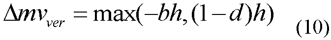
- By means of determining the affine transformation parameters a, b, c, and d, and the distance between the control points, the first component and the second component of the motion vector difference of the affine block may be determined.
- It should be understood that, when the 4-parameter affine transformation model or the 2-parameter affine transformation model is used, the method for determining the motion vector difference is essentially the same as the determining method when the 6-parameter affine transformation model is used. For brevity, details are not described again herein.
- In this embodiment of the present invention, optionally, in the coding process, the affine transformation parameter may be obtained by computing each coefficient iteratively, for example, adding 1 to the coefficient a to determine whether a motion compensation prediction signal in the model is optimal. Alternatively, the affine transformation parameter may be obtained through derivation according to an affine transformation coefficient of an adjacent affine block. However, the present invention is not limited thereto.
- In this embodiment of the present invention, optionally, a motion vector of the first control point, a motion vector of the second control point, a motion vector of the third control point, and a motion vector of the fourth control point may be determined.
- Correspondingly, S1103 is specifically: determining a difference between a horizontal component of the motion vector of the first control point and a horizontal component of the motion vector of the second control point as the first horizontal component difference; and determining a difference between a vertical component of the motion vector of the first control point and a vertical component of the motion vector of the second control point as the first vertical component difference.
- S1105 is specifically: determining a difference between a horizontal component of the motion vector of the third control point and a horizontal component of the motion vector of the fourth control point as the second horizontal component difference; and determining a difference between a vertical component of the motion vector of the third control point and a vertical component of the motion vector of the fourth control point as the second vertical component difference.
- Specifically, the motion vectors of the control points may be directly determined. By means of computing the differences between the components of the motion vectors, the first component and the second component of the motion vector difference of the affine block may be directly obtained.
- For example,
FIG. 5 is a schematic diagram of an affine picture block and control points according to an embodiment of the present invention. Two control points A and B are on a same horizontal line, and have a distance w. Two control points C and D are on a same vertical line, and have a distance h. If motion vectors of the control points A, B, C, and D are known, the first component and the second component of the motion vector difference of the affine block may be determined according to formulas (11) and (12):

- In this embodiment of the present invention, optionally, the control points A and C may be the same pixel.
- In this embodiment of the present invention, optionally, the control points A, B, C, and D may be vertices of the affine block. In this case, a distance between the control points A and B is a width W of the affine block, and a distance between the control points C and D is a height H of the affine block.
- In this embodiment of the present invention, optionally, the first control point and the second control point are two adjacent pixels, and the third control point and the fourth control point are two adjacent pixels.
- S1103 and S1105 are specifically: determining a motion vector of a first pixel, a motion vector of a second pixel, and a motion vector of a third pixel, where the first pixel, the second pixel, and the third pixel are non-overlapping pixels; determining a second horizontal distance and a second vertical distance between the first pixel and the second pixel; determining a third horizontal distance and a third vertical distance between the first pixel and the third pixel; and determining the first horizontal component difference, the first vertical component difference, the second horizontal component difference, and the second vertical component difference according to the motion vector of the first pixel, the motion vector of the second pixel, the motion vector of the third pixel, the second horizontal distance, the second vertical distance, the third horizontal distance, and the third vertical distance.
- Specifically, assuming that A, B, and C are any three non-overlapping pixels in the picture block, positions of the three pixels are shown in
FIG. 6 , and motion vectors of the three pixels are (vxA, vyA ), (vxB, vyB ), and (vxC, vyC ) respectively. A distance between the pixel A and the pixel B in a horizontal direction is w 1, and a distance in a vertical direction is h 1. A distance between the pixel A and the pixel C in the horizontal direction is w 2, and a distance in the vertical direction is h 2. A distance between the pixel B and the pixel C in the horizontal direction is w 2 -w 1, and a distance in the vertical direction is h 1+h 2. It is assumed that horizontal component differences of motion vectors of two adjacent pixels in the horizontal direction are Δmvxhor and Δmvyhor respectively, and vertical component differences of motion vectors of two adjacent pixels in the vertical direction are Δmvxver and Δmvyver respectively. Because motion vectors in the picture block change linearly, Δmvxhor , Δmvyhor, Δmvxver, and Δmvyver may be determined by determining motion vectors of the pixels A, B, and C. In this way, motion vector differences of adjacent pixels in the picture block may be determined, and specifically, may be determined according to formulas (13) to (16):


- In this embodiment of the present invention, optionally, the coding device may obtain motion vectors of all control points by performing a motion estimation search; may obtain motion vectors of all control points from adjacent picture blocks; may compute motion vectors of all control points according to the affine transformation model; may obtain motion vectors of some control points by performing a motion estimation search, and obtain motion vectors of other control points from adjacent picture blocks; may obtain motion vectors of some control points by performing an affine motion estimation search, and obtain motion vectors of other control points through computation according to the affine transformation model; or may obtain motion vectors of some control points from adjacent picture blocks, and compute motion vectors of other control points according to the affine transformation model. However, the present invention is not limited thereto.
- Optionally, in S1200, a third preset value may be determined as the motion vector precision of the affine picture block; or the motion vector precision of the affine picture block may be determined according to a feature of a picture block adjacent to the affine picture block, where the adjacent picture block is a picture block spatially and/or temporally adjacent to the affine picture block.
- Specifically, a value of a motion vector of the affine block may be an integer. In this case, the motion vector is of integer-pixel precision, that is, the pixel precision is 1. Alternatively, a value of a motion vector may not be an integer. In this case, the motion vector is of sub-pixel precision, including precision such as 1/2, 1/4, or 1/8.
FIG. 7 shows a 4x4 picture block, where × indicates a pixel in an integer-pixel position, and a captured picture has only pixels in integer-pixel positions. O indicates a pixel in a 1/2 precision position, and needs to be obtained by interpolating a pixel in an integer-pixel position. Values of pixels in other precision positions need to be obtained by further interpolating pixels in integer-pixel precision positions or pixels in 1/2 precision positions. If a motion vector of a current pixel is an integer, the motion vector points to a position of × in the reference picture. If the motion vector of the current pixel is of 1/2 precision, the motion vector points to a position of O in the reference picture. - The motion vector precision of the affine block is highest precision of motion vectors of all pixels in the affine block. The motion vector precision of the affine block may be preset, for example, integer-pixel precision, or precision such as 1/2, 1/4, 1/8, or 1/16. Alternatively, the motion vector precision may be determined according to a feature of a picture block adjacent to the affine picture block. For example, if an adjacent picture is relatively smooth, it may be predicted that the current affine block is also relatively smooth. Therefore, higher motion vector precision such as 1/8 or 1/16 precision may be selected. Otherwise, lower motion vector precision such as integer-pixel precision or 1/2 precision may be selected. The obtained precision is indicated by MvAc.
- Optionally, as shown in
FIG. 8 , S1300 specifically includes the following steps: - S1301. Determine a ratio of a product of the motion vector precision and the first horizontal distance to the first component of the motion vector difference as a length of the affine motion compensation picture subblock in a horizontal direction.
- S1302. Determine a ratio of a product of the motion vector precision and the first vertical distance to the second component of the motion vector difference as a length of the affine motion compensation picture subblock in a vertical direction.
- Specifically, generally obtained motion vector differences Δmvhor and Δmvver are relatively small, indicating that precision of a motion vector of each pixel is excessively high, for example, 1/32 or 1/64. Excessively high motion vector precision contributes little to compression efficiency of a video, and causes a huge amount of computation. Therefore, the affine block is divided into multiple affine-MC blocks according to previously obtained expected motion vector precision MvAc to ensure that motion vector precision of each affine-MC block reaches MvAc.
- In this embodiment of the present invention, optionally, assuming that the horizontal distance between the first control point and the second control point is w , and that the vertical distance between the third control point and the fourth control point is h, and assuming that a width of the affine-MC block is aMcW and that a height of the affine-MC block is aMcH, aMcW and aMcH may be determined according to formulas (19):

- This is equivalent to:

- In this embodiment of the present invention, optionally, when the first control point, the second control point, the third control point, and the fourth control point are vertices of the affine block, the horizontal distance between the first control point and the second control point is the width W of the affine block, and the vertical distance between the third control point and the fourth control point is the height H of the affine block. In this case, the width aMcW and the height aMcH of the affine-MC block may be determined according to formulas (20):

- This is equivalent to:

- In this embodiment of the present invention, optionally, when the first control point and the second control point are adjacent control points, and the third control point and the fourth control point are adjacent control points, the first horizontal distance between the first control point and the second control point is 1, that is, the first control point is separated from the second control point by an integer quantity of pixels; the first vertical distance between the third control point and the fourth control point is 1, that is, the third control point is separated from the fourth control point by an integer quantity of pixels. In this case, the formulas (19) may be simplified to formulas (21):

- This is equivalent to:

- Therefore, in the video picture coding method according to this embodiment of the present invention, the coding device determines the size of the affine motion compensation picture subblock according to the determined motion vector difference of the affine picture block, the determined motion vector precision, and the distance between the control points, and performs coding processing on the affine picture block according to the size of the affine motion compensation picture subblock. In this way, a picture subblock of an appropriate size is selected in the coding process, so that coding complexity can be reduced and coding efficiency can be improved, while motion compensation prediction efficiency in affine transformation is maintained.
- Optionally, as shown in
FIG. 9 , S1300 includes the following steps. - S1303. When a ratio of a product of the motion vector precision and the first horizontal distance to the first component of the motion vector difference is greater than or equal to a first preset value, determine the ratio as a length of the affine motion compensation picture subblock in a horizontal direction; or
when a ratio of a product of the motion vector precision and the first horizontal distance to the first component of the motion vector difference is less than the first preset value, determine the first preset value as a length of the affine motion compensation picture subblock in a horizontal direction. - S1304. When a ratio of a product of the motion vector precision and the first vertical distance to the second component of the motion vector difference is greater than or equal to a second preset value, determine the ratio as a length of the affine motion compensation picture subblock in a vertical direction; or
when a ratio of a product of the motion vector precision and the first vertical distance to the second component of the motion vector difference is less than the second preset value, determine the second preset value as a length of the affine motion compensation picture subblock in a vertical direction. - Specifically, for a hardware implementation in the coding process, a lower limit may be set for the width and the height of the affine-MC block. When the computed width or height is less than the preset lower limit, the preset lower limit is determined as the width or the height of the affine-MC block. Preferably, the lower limit may be set to 4, but may also be set to another numeric value according to an actual requirement. For example, a lower limit of the width may be set to 2, and a specified value of the height is set to 3; or a lower limit of the width is set to 1, and a specified value of the height is set to 2. This is not limited in the present invention.
- Optionally, as shown in
FIG. 10 , S1400 includes the following steps: - S1401. Determine a motion vector of each affine motion compensation picture subblock in the affine motion compensation picture subblocks.
- S1402. Determine a motion compensation prediction signal of each affine motion compensation picture subblock according to the motion vector of each affine motion compensation picture subblock.
- S1403. Determine a prediction residual signal of each affine motion compensation picture subblock according to the motion compensation prediction signal of each affine motion compensation picture subblock.
- S1404. Code the prediction residual signal of each affine motion compensation picture subblock.
- It should be understood that, in this embodiment of the present invention, each affine-MC block may include multiple pixels, and a motion vector of a pixel needs to be selected from each affine-MC as a motion vector of the affine-MC block.
- Optionally, in S1401, a motion vector of a pixel in a central position of the affine-MC block may be selected as the motion vector of the affine-MC block; an average value of motion vectors of all pixels in the affine-MC block may be used as the motion vector of the affine-MC block; or a motion vector of a pixel in an upper left corner of the affine-MC block may be selected as the motion vector of the affine-MC block. However, the present invention is not limited thereto.
- In this embodiment of the present invention, optionally, signals of boundary pixels of each affine motion compensation picture subblock are filtered, and the boundary pixels are pixels in one or more rows at a boundary of each affine motion compensation picture subblock.
- In this embodiment of the present invention, optionally, the signal of the boundary pixel includes a motion compensation prediction signal and/or a reconstructed signal, and the reconstructed signal is a sum of the motion compensation prediction signal and a reconstructed residual signal.
- Specifically, as shown in
FIG. 11 , a thick solid line block indicates an affine block, a thin solid line block indicates an affine-MC block, a dashed line block indicates pixels at boundaries of adjacent affine-MC blocks, and a cross indicates a pixel. A region of a dashed line block inFIG. 11 includes pixels of adjacent affine-MC blocks in two rows or two columns at boundaries of the affine-MC blocks, or may include one row or one column, or three rows or three columns at the boundaries of the affine-MC blocks. Because motion vectors of adjacent affine-MC blocks may be different, prediction signals obtained from the reference picture are not adjacent in the reference picture. This causes discontinuity of prediction signals at the boundaries of the adjacent affine-MC blocks, and therefore causes discontinuity of residuals, and affects coding efficiency of the residuals. Therefore, filtering the motion compensation prediction signals at the boundaries of the affine-MC blocks is considered. - A reconstructed signal is generally obtained by adding a reconstructed residual signal to a motion compensation prediction signal. Generally, lossy coding is used for the residual signal. This causes distortion between the reconstructed residual signal and an original residual signal. Distortion directions of pixels at the boundaries of adjacent affine-MC blocks may be inconsistent. For example, a right pixel of a first affine-MC block becomes larger due to distortion, and a left pixel of a right adjacent affine-MC block becomes smaller due to distortion. This causes discontinuity of pixel values at boundaries of reconstructed pixels of the affine-MC blocks, and impairs subjective and objective effects. Therefore, the reconstructed signals need to be filtered.
- In this embodiment of the present invention, optionally, filtering may be performing by using a lowpass filter, so that pixel values in the boundary region change more smoothly. For example, filtering is performed by using a Gauss filter. However, the present invention is not limited thereto.
- In this embodiment of the present invention, optionally, filtering may be performed by using an overlapped block motion compensation (Overlapped block motion compensation, "OBMC" for short) method. Motion compensation prediction is performed on a to-be-filtered pixel by using a motion vector of an affine-MC block adjacent to the to-be-filtered pixel, and weighted averaging is performed on the obtained motion compensation prediction signal and a motion compensation prediction signal obtained by using a motion vector of the to-be-filtered pixel, to obtain a final motion compensation prediction signal.
- To better prove beneficial effects of this embodiment of the present invention relative to the prior art, an LDP test structure is used to test coding complexity and coding efficiency when the method in this embodiment of the present invention and the method in the prior art are used to perform coding. A result is shown in Table 1.
Table 1 Class Sequence The method in the present invention relative to the method in the prior art LDP Tractor -0.2% BlueSky 0.0% SpinCalendar 0.0% Jets -0.5% Enct 86% Dect 78% - As can be seen from Table 1, using the video picture coding method in this embodiment of the present invention can improve coding efficiency and reduce a coding time.
- Therefore, in the video picture coding method according to this embodiment of the present invention, the coding device determines the size of the affine motion compensation picture subblock according to the determined motion vector difference of the affine picture block, the determined motion vector precision, and the distance between the control points, and performs coding processing on the affine picture block according to the size of the affine motion compensation picture subblock. In this way, a picture subblock of an appropriate size is selected in the coding process, so that coding complexity can be reduced, and coding efficiency can be improved.
- The video picture coding method according to this embodiment of the present invention is hereinbefore described in detail with reference to
FIG. 1 to FIG. 11 . A video picture decoding method according to an embodiment of the present invention is hereinafter described in detail with reference toFIG. 12 to FIG. 18 . It should be noted that, related operations of a decoder are essentially consistent with those of an encoder. To avoid repetition, details are not described again herein. -
FIG. 12 shows a schematic flowchart of a video picture decoding method according to an embodiment of the present invention. The method shown inFIG. 12 may be performed by a decoding device, for example, a decoder. Specifically, as shown inFIG. 12 , themethod 2000 includes the following steps. - S2100. Determine a motion vector difference of an affine picture block.
- S2200. Determine motion vector precision of the affine picture block.
- S2300. Determine a size of an affine motion compensation picture subblock in the affine picture block according to the motion vector difference, the motion vector precision, and a distance between control points in the affine picture block, where the control points are pixels used to determine the motion vector difference.
- S2400. Perform decoding processing on the affine picture block according to the size of the affine motion compensation picture subblock.
- Specifically, the decoding device determines the motion vector difference of the affine picture block according to the determined control points, determines the motion vector precision of the affine picture block, determines the size of the affine motion compensation picture subblock in the affine picture block according to the determined motion vector difference, the determined motion vector precision, and the distance between the control points, and performs decoding processing on the affine picture block according to the determined size.
- Therefore, in the video picture decoding method according to this embodiment of the present invention, the decoding device determines the size of the affine motion compensation picture subblock according to the determined motion vector difference of the affine picture block, the determined motion vector precision, and the distance between the control points, and performs decoding processing on the affine picture block according to the determined size. In this way, a picture subblock of an appropriate size is selected in a decoding process, so that decoding complexity can be reduced, and decoding efficiency can be improved.
- Preferably, as shown in
FIG. 13 , S2100 includes the following steps: - S2101. Determine a first component of the motion vector difference according to a difference between motion vectors of a first control point and a second control point that are located on a same horizontal line.
- S2102. Determine a second component of the motion vector difference according to a difference between motion vectors of a third control point and a fourth control point that are located on a same vertical line.
- A first horizontal distance exists between the first control point and the second control point, and a first vertical distance exists between the third control point and the fourth control point.
- It should be understood that, in this embodiment of the present invention, the first component of the motion vector difference is a horizontal component of the motion vector difference, and the second component of the motion vector difference is a vertical component of the motion vector difference.
- Optionally, as shown in
FIG. 14 , S2101 specifically includes the following steps: - S2103. Determine a first horizontal component difference and a first vertical component difference between the motion vectors of the first control point and the second control point.
- S2104. Determine a larger one of the first horizontal component difference and the first vertical component difference as the first component of the motion vector difference.
- Correspondingly, as shown in
FIG. 15 , S2102 specifically includes the following steps: - S2105. Determine a second horizontal component difference and a second vertical component difference between the motion vectors of the third control point and the fourth control point.
- S2106. Determine a larger one of the second horizontal component difference and the second vertical component difference as the second component of the motion vector difference.
- In this embodiment of the present invention, optionally, an affine transformation parameter of a pixel in the affine picture block may be determined, and pixels in the affine picture block have the same affine transformation parameter.
- Correspondingly, S2103 is specifically: determining the first horizontal component difference and the first vertical component difference according to the affine transformation parameter and the first horizontal distance.
- S2105 is specifically: determining the second horizontal component difference and the second vertical component difference according to the affine transformation parameter and the first vertical distance.
- In this embodiment of the present invention, optionally, a motion vector of the first control point, a motion vector of the second control point, a motion vector of the third control point, and a motion vector of the fourth control point may be determined.
- Correspondingly, S2103 is specifically: determining a difference between a horizontal component of the motion vector of the first control point and a horizontal component of the motion vector of the second control point as the first horizontal component difference; and determining a difference between a vertical component of the motion vector of the first control point and a vertical component of the motion vector of the second control point as the first vertical component difference.
- S2105 is specifically: determining a difference between a horizontal component of the motion vector of the third control point and a horizontal component of the motion vector of the fourth control point as the second horizontal component difference; and determining a difference between a vertical component of the motion vector of the third control point and a vertical component of the motion vector of the fourth control point as the second vertical component difference.
- In this embodiment of the present invention, optionally, the first control point and the second control point are two adjacent pixels, and the third control point and the fourth control point are two adjacent pixels.
- S2103 and S2105 are specifically: determining a motion vector of a first pixel, a motion vector of a second pixel, and a motion vector of a third pixel, where the first pixel, the second pixel, and the third pixel are non-overlapping pixels; determining a second horizontal distance and a second vertical distance between the first pixel and the second pixel; determining a third horizontal distance and a third vertical distance between the first pixel and the third pixel; and determining the first horizontal component difference, the first vertical component difference, the second horizontal component difference, and the second vertical component difference according to the motion vector of the first pixel, the motion vector of the second pixel, the motion vector of the third pixel, the second horizontal distance, the second vertical distance, the third horizontal distance, and the third vertical distance.
- In this embodiment of the present invention, optionally, the decoding device may obtain motion vectors of all control points by parsing a bit stream; may obtain motion vectors of all control points from adjacent picture blocks; may compute motion vectors of all control points according to an affine transformation model; may obtain motion vectors of some control points by parsing a bit stream, and obtain motion vectors of other control points from adjacent picture blocks; may obtain motion vectors of some control points by parsing a bit stream, and obtain motion vectors of other control points through computation according to an affine transformation model; or may obtain motion vectors of some control points from adjacent picture blocks, and compute motion vectors of other control points according to an affine transformation model. However, the present invention is not limited thereto.
- Optionally, in S2200, a third preset value may be determined as the motion vector precision of the affine picture block; or the motion vector precision of the affine picture block is determined according to a feature of a picture block adjacent to the affine picture block, where the adjacent picture block is a picture block spatially and/or temporally adjacent to the affine picture block.
- Optionally, as shown in
FIG. 16 , S2300 specifically includes the following steps: - S2301. Determine a ratio of a product of the motion vector precision and the first horizontal distance to the first component of the motion vector difference as a length of the affine motion compensation picture subblock in a horizontal direction.
- S2302. Determine a ratio of a product of the motion vector precision and the first vertical distance to the second component of the motion vector difference as a length of the affine motion compensation picture subblock in a vertical direction.
- Optionally, as shown in
FIG. 17 , S2300 includes the following steps: - S2303. When a ratio of a product of the motion vector precision and the first horizontal distance to the first component of the motion vector difference is greater than or equal to a first preset value, determine the ratio as a length of the affine motion compensation picture subblock in a horizontal direction; or
when a ratio of a product of the motion vector precision and the first horizontal distance to the horizontal component of the motion vector difference is less than the first preset value, determine the first preset value as a length of the affine motion compensation picture subblock in a horizontal direction. - S2304. When a ratio of a product of the motion vector precision and the first vertical distance to the vertical component of the motion vector difference is greater than or equal to a second preset value, determine the ratio as a length of the affine motion compensation picture subblock in a vertical direction; or
when a ratio of a product of the motion vector precision and the first vertical distance to the vertical component of the motion vector difference is less than the second preset value, determine the second preset value as a length of the affine motion compensation picture subblock in a vertical direction. - Optionally, as shown in
FIG. 18 , S2400 includes the following steps: - S2401. Determine a motion vector of each affine motion compensation picture subblock in the affine motion compensation picture subblocks.
- S2402. Determine a motion compensation prediction signal of each affine motion compensation picture subblock according to the motion vector of each affine motion compensation picture subblock.
- S2403. Determine a prediction residual signal of each affine motion compensation picture subblock according to the motion compensation prediction signal of each affine motion compensation picture subblock.
- S2404. Decode the prediction residual signal of each affine motion compensation picture subblock.
- In this embodiment of the present invention, optionally, signals of boundary pixels of each affine motion compensation picture subblock are filtered, and the boundary pixels are pixels in one or more rows at a boundary of each affine motion compensation picture subblock.
- In this embodiment of the present invention, optionally, the signal of the boundary pixel includes a motion compensation prediction signal and/or a reconstructed signal, and the reconstructed signal is a sum of the motion compensation prediction signal and a reconstructed residual signal. Therefore, in the video picture decoding method according to this embodiment of the present invention, the decoding device determines the size of the affine motion compensation picture subblock according to the determined motion vector difference of the affine picture block, the motion vector precision, and the distance between the control points, and performs decoding processing on the affine picture block according to the determined size. In this way, a picture subblock of an appropriate size is selected in the decoding process, so that decoding complexity can be reduced, and decoding efficiency can be improved.
- Optionally, the decoding method in the present invention may also be:
- parsing a bit stream to obtain a motion vector difference of an affine picture block and motion vector precision of the affine picture block, where pixels in the affine picture block have a same affine transformation parameter;
- determining a size of an affine motion compensation picture subblock in the affine picture block according to the motion vector difference, the motion vector precision, and a distance between control points in the affine picture block, where the control points are pixels used to determine the motion vector difference; and
- performing decoding processing on the affine picture block according to the size of the affine motion compensation picture subblock.
- Alternatively, the decoding method may be:
- parsing a bit stream to obtain affine picture block information;
- determining a size of an affine motion compensation picture subblock in the affine picture block according to the affine picture block information; and
- performing decoding processing on the affine picture block according to the size of the affine motion compensation picture subblock.
- In such a manner, the decoder may directly use a parameter sent by an encoder to the decoder to determine the size of the affine motion compensation picture subblock without re-computation, and further reduce computational complexity.
- The following describes in detail a coding device according to an embodiment of the present invention with reference to
FIG. 19 andFIG. 20 . As shown inFIG. 19 , thecoding device 10 includes: - a first determining
module 11, configured to determine a motion vector difference of an affine picture block; - a second determining
module 12, configured to determine motion vector precision of the affine picture block; - a third determining
module 13, configured to determine a size of an affine motion compensation picture subblock in the affine picture block according to the motion vector difference determined by the first determiningmodule 11, the motion vector precision determined by the second determiningmodule 12, and a distance between control points in the affine picture block, where the control points are pixels used to determine the motion vector difference; and - a
coding module 14, configured to perform coding processing on the affine picture block according to the size of the affine motion compensation picture subblock that is determined by the third determiningmodule 13. - Specifically, the coding device determines the motion vector difference of the affine picture block according to the determined control points, determines the motion vector precision of the affine picture block, determines the size of the affine motion compensation picture subblock in the affine picture block according to the determined motion vector difference, the determined motion vector precision, and the distance between the control points, and performs coding processing on the affine picture block according to the determined size.
- Therefore, the coding device according to this embodiment of the present invention determines the size of the affine motion compensation picture subblock according to the determined motion vector difference of the affine picture block, the determined motion vector precision, and the distance between the control points, and performs coding processing on the affine picture block according to the size of the affine motion compensation picture subblock. In this way, a picture subblock of an appropriate size is selected in a coding process, so that coding complexity can be reduced, and coding efficiency can be improved.
- In this embodiment of the present invention, optionally, the first determining
module 11 is specifically configured to: determine a first component of the motion vector difference according to a difference between motion vectors of a first control point and a second control point that are located on a same horizontal line; and determine a second component of the motion vector difference according to a difference between motion vectors of a third control point and a fourth control point that are located on a same vertical line; where
a first horizontal distance exists between the first control point and the second control point, and a first vertical distance exists between the third control point and the fourth control point. - In this embodiment of the present invention, optionally, the first determining
module 11 is specifically configured to: determine a first horizontal component difference and a first vertical component difference between the motion vectors of the first control point and the second control point; determine a larger one of the first horizontal component difference and the first vertical component difference as the first component of the motion vector difference; determine a second horizontal component difference and a second vertical component difference between the motion vectors of the third control point and the fourth control point; and determine a larger one of the second horizontal component difference and the second vertical component difference as the second component of the motion vector difference. - In this embodiment of the present invention, optionally, the first determining
module 11 is specifically configured to: determine an affine transformation parameter of a pixel in the affine picture block, where pixels in the affine picture block have the same affine transformation parameter; determine the first horizontal component difference and the first vertical component difference according to the affine transformation parameter and the first horizontal distance; and determine the second horizontal component difference and the second vertical component difference according to the affine transformation parameter and the first vertical distance. - In this embodiment of the present invention, optionally, the first determining
module 11 is specifically configured to: determine a motion vector of the first control point, a motion vector of the second control point, a motion vector of the third control point, and a motion vector of the fourth control point; determine a difference between a horizontal component of the motion vector of the first control point and a horizontal component of the motion vector of the second control point as the first horizontal component difference; determine a difference between a vertical component of the motion vector of the first control point and a vertical component of the motion vector of the second control point as the first vertical component difference; determine a difference between a horizontal component of the motion vector of the third control point and a horizontal component of the motion vector of the fourth control point as the second horizontal component difference; and determine a difference between a vertical component of the motion vector of the third control point and a vertical component of the motion vector of the fourth control point as the second vertical component difference. - In this embodiment of the present invention, optionally, the first control point and the second control point are two adjacent pixels, and the third control point and the fourth control point are two adjacent pixels.
- The first determining
module 11 is specifically configured to: determine a motion vector of a first pixel, a motion vector of a second pixel, and a motion vector of a third pixel, where the first pixel, the second pixel, and the third pixel are non-overlapping pixels; determine a second horizontal distance and a second vertical distance between the first pixel and the second pixel; determine a third horizontal distance and a third vertical distance between the first pixel and the third pixel; and determine the first horizontal component difference, the first vertical component difference, the second horizontal component difference, and the second vertical component difference according to the motion vector of the first pixel, the motion vector of the second pixel, the motion vector of the third pixel, the second horizontal distance, the second vertical distance, the third horizontal distance, and the third vertical distance. - In this embodiment of the present invention, optionally, the third determining
module 13 is specifically configured to: determine a ratio of a product of the motion vector precision and the first horizontal distance to the first component of the motion vector difference as a length of the affine motion compensation picture subblock in a horizontal direction; and determine a ratio of a product of the motion vector precision and the first vertical distance to the second component of the motion vector difference as a length of the affine motion compensation picture subblock in a vertical direction. - In this embodiment of the present invention, optionally, the third determining
module 13 is specifically configured to: - when a ratio of a product of the motion vector precision and the first horizontal distance to the first component of the motion vector difference is greater than or equal to a first preset value, determine the ratio as a length of the affine motion compensation picture subblock in a horizontal direction; or when a ratio of a product of the motion vector precision and the first horizontal distance to the first component of the motion vector difference is less than the first preset value, determine the first preset value as a length of the affine motion compensation picture subblock in a horizontal direction; and
- when a ratio of a product of the motion vector precision and the first vertical distance to the second component of the motion vector difference is greater than or equal to a second preset value, determine the ratio as a length of the affine motion compensation picture subblock in a vertical direction; or when a ratio of a product of the motion vector precision and the first vertical distance to the second component of the motion vector difference is less than the second preset value, determine the second preset value as a length of the affine motion compensation picture subblock in a vertical direction.
- In this embodiment of the present invention, optionally, the first control point and the third control point are the same pixel.
- In this embodiment of the present invention, optionally, the first control point, the second control point, the third control point, and the fourth control point are vertices of the affine picture block.
- In this embodiment of the present invention, optionally, the first preset value is 4, and/or the second preset value is 4.
- In this embodiment of the present invention, optionally, the second determining
module 12 is specifically configured to: determine a third preset value as the motion vector precision of the affine picture block; or determine the motion vector precision of the affine picture block according to a feature of a picture block adjacent to the affine picture block, where the adjacent picture block is a picture block spatially and/or temporally adjacent to the affine picture block. - In this embodiment of the present invention, optionally, the
coding module 14 is specifically configured to: determine a motion vector of each affine motion compensation picture subblock in the affine motion compensation picture subblocks; determine a motion compensation prediction signal of each affine motion compensation picture subblock according to the motion vector of each affine motion compensation picture subblock; determine a prediction residual signal of each affine motion compensation picture subblock according to the motion compensation prediction signal of each affine motion compensation picture subblock; and code the prediction residual signal of each affine motion compensation picture subblock. - In this embodiment of the present invention, optionally, as shown in
FIG. 20 , thecoding device 10 further includes:
afiltering module 15, configured to filter signals of boundary pixels of each affine motion compensation picture subblock, where the boundary pixels are pixels in one or more rows at a boundary of each affine motion compensation picture subblock. - In this embodiment of the present invention, optionally, the signal of the boundary pixel includes a motion compensation prediction signal and/or a reconstructed signal, and the reconstructed signal is a sum of the motion compensation prediction signal and a reconstructed residual signal.
- It should be understood that, the
coding device 10 according to this embodiment of the present invention may correspondingly perform the videopicture coding method 1000 in the embodiments of the present invention, and the foregoing and other operations and/or functions of the modules in thecoding device 10 are separately intended to implement the corresponding procedures of the method inFIG. 1 to FIG. 11 . For brevity, details are not described again herein. - Therefore, the coding device according to this embodiment of the present invention determines the size of the affine motion compensation picture subblock according to the determined motion vector difference of the affine picture block, the determined motion vector precision, and the distance between the control points, and performs coding processing on the affine picture block according to the size. In this way, a picture subblock of an appropriate size is selected in the coding process, so that coding complexity can be reduced, and coding efficiency can be improved.
- The following describes in detail a decoding device according to an embodiment of the present invention with reference to
FIG. 21 and FIG. 22 . As shown inFIG. 21 , thedecoding device 20 includes: - a first determining
module 21, configured to determine a motion vector difference of an affine picture block; - a second determining
module 22, configured to determine motion vector precision of the affine picture block; - a third determining
module 23, configured to determine a size of an affine motion compensation picture subblock in the affine picture block according to the motion vector difference determined by the first determiningmodule 21, the motion vector precision determined by the second determiningmodule 22, and a distance between control points in the affine picture block, where the control points are pixels used to determine the motion vector difference; and - a
decoding module 24, configured to perform decoding processing on the affine picture block according to the size of the affine motion compensation picture subblock that is determined by the third determiningmodule 23. - Specifically, the decoding device determines the motion vector difference of the affine picture block according to the determined control points, determines the motion vector precision of the affine picture block, determines the size of the affine motion compensation picture subblock in the affine picture block according to the determined motion vector difference, the determined motion vector precision, and the distance between the control points, and performs decoding processing on the affine picture block according to the determined size.
- Therefore, the decoding device according to this embodiment of the present invention determines the size of the affine motion compensation picture subblock according to the determined motion vector difference of the affine picture block, the determined motion vector precision, and the distance between the control points, and performs decoding processing on the affine picture block according to the size of the affine motion compensation picture subblock. In this way, a picture subblock of an appropriate size is selected in a decoding process, so that decoding complexity can be reduced, and decoding efficiency can be improved.
- In this embodiment of the present invention, optionally, the first determining
module 21 is specifically configured to: determine a first component of the motion vector difference according to a difference between motion vectors of a first control point and a second control point that are located on a same horizontal line; and determine a second component of the motion vector difference according to a difference between motion vectors of a third control point and a fourth control point that are located on a same vertical line; where
a first horizontal distance exists between the first control point and the second control point, and a first vertical distance exists between the third control point and the fourth control point. - In this embodiment of the present invention, optionally, the first determining
module 21 is specifically configured to: determine a first horizontal component difference and a first vertical component difference between the motion vectors of the first control point and the second control point; determine a larger one of the first horizontal component difference and the first vertical component difference as the first component of the motion vector difference; determine a second horizontal component difference and a second vertical component difference between the motion vectors of the third control point and the fourth control point; and determine a larger one of the second horizontal component difference and the second vertical component difference as the second component of the motion vector difference. - In this embodiment of the present invention, optionally, the first determining
module 21 is specifically configured to: determine an affine transformation parameter of a pixel in the affine picture block, where pixels in the affine picture block have the same affine transformation parameter; determine the first horizontal component difference and the first vertical component difference according to the affine transformation parameter and the first horizontal distance; and determine the second horizontal component difference and the second vertical component difference according to the affine transformation parameter and the first vertical distance. - In this embodiment of the present invention, optionally, the first determining
module 21 is specifically configured to: determine a motion vector of the first control point, a motion vector of the second control point, a motion vector of the third control point, and a motion vector of the fourth control point; determine a difference between a horizontal component of the motion vector of the first control point and a horizontal component of the motion vector of the second control point as the first horizontal component difference; determine a difference between a vertical component of the motion vector of the first control point and a vertical component of the motion vector of the second control point as the first vertical component difference; determine a difference between a horizontal component of the motion vector of the third control point and a horizontal component of the motion vector of the fourth control point as the second horizontal component difference; and determine a difference between a vertical component of the motion vector of the third control point and a vertical component of the motion vector of the fourth control point as the second vertical component difference. - In this embodiment of the present invention, optionally, the first control point and the second control point are two adjacent pixels, and the third control point and the fourth control point are two adjacent pixels.
- The first determining
module 21 is specifically configured to: determine a motion vector of a first pixel, a motion vector of a second pixel, and a motion vector of a third pixel, where the first pixel, the second pixel, and the third pixel are non-overlapping pixels; determine a second horizontal distance and a second vertical distance between the first pixel and the second pixel; determine a third horizontal distance and a third vertical distance between the first pixel and the third pixel; and determine the first horizontal component difference, the first vertical component difference, the second horizontal component difference, and the second vertical component difference according to the motion vector of the first pixel, the motion vector of the second pixel, the motion vector of the third pixel, the second horizontal distance, the second vertical distance, the third horizontal distance, and the third vertical distance. - In this embodiment of the present invention, optionally, the third determining
module 23 is specifically configured to: determine a ratio of a product of the motion vector precision and the first horizontal distance to the first component of the motion vector difference as a length of the affine motion compensation picture subblock in a horizontal direction; and determine a ratio of a product of the motion vector precision and the first vertical distance to the second component of the motion vector difference as a length of the affine motion compensation picture subblock in a vertical direction. - In this embodiment of the present invention, optionally, the third determining
module 23 is specifically configured to: - when a ratio of a product of the motion vector precision and the first horizontal distance to the first component of the motion vector difference is greater than or equal to a first preset value, determine the ratio as a length of the affine motion compensation picture subblock in a horizontal direction; or when a ratio of a product of the motion vector precision and the first horizontal distance to the first component of the motion vector difference is less than the first preset value, determine the first preset value as a length of the affine motion compensation picture subblock in a horizontal direction; and
- when a ratio of a product of the motion vector precision and the first vertical distance to the second component of the motion vector difference is greater than or equal to a second preset value, determine the ratio as a length of the affine motion compensation picture subblock in a vertical direction; or when a ratio of a product of the motion vector precision and the first vertical distance to the second component of the motion vector difference is less than the second preset value, determine the second preset value as a length of the affine motion compensation picture subblock in a vertical direction.
- In this embodiment of the present invention, optionally, the first control point and the third control point are the same pixel.
- In this embodiment of the present invention, optionally, the first control point, the second control point, the third control point, and the fourth control point are vertices of the affine picture block.
- In this embodiment of the present invention, optionally, the first preset value is 4, and/or the second preset value is 4.
- In this embodiment of the present invention, optionally, the second determining
module 22 is specifically configured to: determine a third preset value as the motion vector precision of the affine picture block; or determine the motion vector precision of the affine picture block according to a feature of a picture block adjacent to the affine picture block, where the adjacent picture block is a picture block spatially and/or temporally adjacent to the affine picture block. - In this embodiment of the present invention, optionally, the
decoding module 24 is specifically configured to: determine a motion vector of each affine motion compensation picture subblock in the affine motion compensation picture subblocks; determine a motion compensation prediction signal of each affine motion compensation picture subblock according to the motion vector of each affine motion compensation picture subblock; determine a prediction residual signal of each affine motion compensation picture subblock according to the motion compensation prediction signal of each affine motion compensation picture subblock; and decode the prediction residual signal of each affine motion compensation picture subblock. - In this embodiment of the present invention, optionally, as shown in
FIG. 22 , thedecoding device 20 further includes:
afiltering module 25, configured to filter signals of boundary pixels of each affine motion compensation picture subblock, where the boundary pixels are pixels in one or more rows at a boundary of each affine motion compensation picture subblock. - In this embodiment of the present invention, optionally, the signal of the boundary pixel includes a motion compensation prediction signal and/or a reconstructed signal, and the reconstructed signal is a sum of the motion compensation prediction signal and a reconstructed residual signal.
- It should be understood that, the
decoding device 20 according to this embodiment of the present invention may correspondingly perform the videopicture decoding method 2000 in the embodiments of the present invention, and the foregoing and other operations and/or functions of the modules in thedecoding device 20 are separately intended to implement the corresponding procedures of the method inFIG. 12 to FIG. 18 . For brevity, details are not described again herein. - Therefore, the decoding device according to this embodiment of the present invention determines the size of the affine motion compensation picture subblock according to the determined motion vector difference of the affine picture block, the determined motion vector precision, and the distance between the control points, and performs decoding processing on the affine picture block according to the size. In this way, a picture subblock of an appropriate size is selected in the decoding process, so that decoding complexity can be reduced, and decoding efficiency can be improved.
- As shown in
FIG. 23 , an embodiment of the present invention further provides acoding device 30, including aprocessor 31, amemory 32, and abus system 33. Theprocessor 31 and thememory 32 are connected by thebus system 33. Thememory 32 is configured to store an instruction. Theprocessor 31 is configured to execute the instruction stored in thememory 32. Thememory 32 of thecoding device 30 stores program code, and theprocessor 31 may invoke the program code stored in thememory 32 to perform the following operations: determining a motion vector difference of an affine picture block; determining motion vector precision of the affine picture block; determining a size of an affine motion compensation picture subblock in the affine picture block according to the motion vector difference, the motion vector precision, and a distance between control points in the affine picture block, where the control points are pixels used to determine the motion vector difference; and performing coding processing on the affine picture block according to the size of the affine motion compensation picture subblock. - Therefore, the coding device according to this embodiment of the present invention determines the size of the affine motion compensation picture subblock according to the determined motion vector difference of the affine picture block, the determined motion vector precision, and the distance between the control points, and performs coding processing on the affine picture block according to the size of the affine motion compensation picture subblock. In this way, a picture subblock of an appropriate size is selected in a coding process, so that coding complexity can be reduced, and coding efficiency can be improved.
- It should be understood that, in this embodiment of the present invention, the
processor 31 may be a central processing unit (Central Processing Unit, "CPU" for short), or theprocessor 31 may be another general purpose processor, a digital signal processor (DSP), an application-specific integrated circuit (ASIC), a field programmable gate array (FPGA), or another programmable logic device, discrete gate or transistor logic device, discrete hardware component, or the like. The general purpose processor may be a microprocessor, or the processor may be any conventional processor, or the like. - The
memory 32 may include a read-only memory and a random access memory, and provide an instruction and data to theprocessor 31. A part of thememory 32 may further include a non-volatile random access memory. For example, thememory 32 may further store information about a device type. - The
bus system 33 may further include a power bus, a control bus, a status signal bus, and the like, in addition to a data bus. However, for clear description, various buses in the figure are marked as thebus system 33. - In an implementation process, each step of the foregoing method may be completed by using an integrated logic circuit of hardware in the
processor 31 or an instruction in a form of software. The steps of the method disclosed with reference to the embodiments of the present invention may be directly performed by a hardware processor, or may be performed by using a combination of hardware in the processor and a software module. The software module may be located in a mature storage medium in the art, such as a random access memory, a flash memory, a read-only memory, a programmable read-only memory, an electrically erasable programmable memory, or a register. The storage medium is located in thememory 32. Theprocessor 31 reads information in thememory 32 and completes the steps in the foregoing method in combination with the hardware of theprocessor 31. To avoid repetition, details are not described again herein. - Optionally, in an embodiment, the
processor 31 is specifically configured to: determine a first component of the motion vector difference according to a difference between motion vectors of a first control point and a second control point that are located on a same horizontal line; and determine a second component of the motion vector difference according to a difference between motion vectors of a third control point and a fourth control point that are located on a same vertical line; where
a first horizontal distance exists between the first control point and the second control point, and a first vertical distance exists between the third control point and the fourth control point. - Optionally, in an embodiment, the
processor 31 is specifically configured to: determine a first horizontal component difference and a first vertical component difference between the motion vectors of the first control point and the second control point; determine a larger one of the first horizontal component difference and the first vertical component difference as the first component of the motion vector difference; determine a second horizontal component difference and a second vertical component difference between the motion vectors of the third control point and the fourth control point; and determine a larger one of the second horizontal component difference and the second vertical component difference as the second component of the motion vector difference. - Optionally, in an embodiment, the
processor 31 is specifically configured to: determine an affine transformation parameter of a pixel in the affine picture block, where pixels in the affine picture block have the same affine transformation parameter; determine the first horizontal component difference and the first vertical component difference according to the affine transformation parameter and the first horizontal distance; and determine the second horizontal component difference and the second vertical component difference according to the affine transformation parameter and the first vertical distance. - Optionally, in an embodiment, the
processor 31 is specifically configured to: determine a motion vector of the first control point, a motion vector of the second control point, a motion vector of the third control point, and a motion vector of the fourth control point; determine a difference between a horizontal component of the motion vector of the first control point and a horizontal component of the motion vector of the second control point as the first horizontal component difference; determine a difference between a vertical component of the motion vector of the first control point and a vertical component of the motion vector of the second control point as the first vertical component difference; determine a difference between a horizontal component of the motion vector of the third control point and a horizontal component of the motion vector of the fourth control point as the second horizontal component difference; and determine a difference between a vertical component of the motion vector of the third control point and a vertical component of the motion vector of the fourth control point as the second vertical component difference. - Optionally, in an embodiment, the first control point and the second control point are two adjacent pixels, and the third control point and the fourth control point are two adjacent pixels.
- The
processor 31 is specifically configured to: determine a motion vector of a first pixel, a motion vector of a second pixel, and a motion vector of a third pixel, where the first pixel, the second pixel, and the third pixel are non-overlapping pixels; determine a second horizontal distance and a second vertical distance between the first pixel and the second pixel; determine a third horizontal distance and a third vertical distance between the first pixel and the third pixel; and determine the first horizontal component difference, the first vertical component difference, the second horizontal component difference, and the second vertical component difference according to the motion vector of the first pixel, the motion vector of the second pixel, the motion vector of the third pixel, the second horizontal distance, the second vertical distance, the third horizontal distance, and the third vertical distance. - Optionally, in an embodiment, the
processor 31 is specifically configured to: determine a ratio of a product of the motion vector precision and the first horizontal distance to the first component of the motion vector difference as a length of the affine motion compensation picture subblock in a horizontal direction; and determine a ratio of a product of the motion vector precision and the first vertical distance to the second component of the motion vector difference as a length of the affine motion compensation picture subblock in a vertical direction. - Optionally, in an embodiment, the
processor 31 is specifically configured to: - when a ratio of a product of the motion vector precision and the first horizontal distance to the first component of the motion vector difference is greater than or equal to a first preset value, determine the ratio as a length of the affine motion compensation picture subblock in a horizontal direction; or when a ratio of a product of the motion vector precision and the first horizontal distance to the first component of the motion vector difference is less than the first preset value, determine the first preset value as a length of the affine motion compensation picture subblock in a horizontal direction; and
- when a ratio of a product of the motion vector precision and the first vertical distance to the second component of the motion vector difference is greater than or equal to a second preset value, determine the ratio as a length of the affine motion compensation picture subblock in a vertical direction; or when a ratio of a product of the motion vector precision and the first vertical distance to the second component of the motion vector difference is less than the second preset value, determine the second preset value as a length of the affine motion compensation picture subblock in a vertical direction.
- Optionally, in an embodiment, the first control point and the third control point are the same pixel.
- Optionally, in an embodiment, the first control point, the second control point, the third control point, and the fourth control point are vertices of the affine picture block.
- Optionally, in an embodiment, the first preset value is 4, and/or the second preset value is 4.
- Optionally, in an embodiment, the
processor 31 is specifically configured to: determine a third preset value as the motion vector precision of the affine picture block; or determine the motion vector precision of the affine picture block according to a feature of a picture block adjacent to the affine picture block, where the adjacent picture block is a picture block spatially and/or temporally adjacent to the affine picture block. - Optionally, in an embodiment, the
processor 31 is specifically configured to: determine a motion vector of each affine motion compensation picture subblock in the affine motion compensation picture subblocks; determine a motion compensation prediction signal of each affine motion compensation picture subblock according to the motion vector of each affine motion compensation picture subblock; determine a prediction residual signal of each affine motion compensation picture subblock according to the motion compensation prediction signal of each affine motion compensation picture subblock; and code the prediction residual signal of each affine motion compensation picture subblock. - Optionally, in an embodiment, the
processor 31 is further configured to filter signals of boundary pixels of each affine motion compensation picture subblock, where the boundary pixels are pixels in one or more rows at a boundary of each affine motion compensation picture subblock. - Optionally, in an embodiment, the signal of the boundary pixel includes a motion compensation prediction signal and/or a reconstructed signal, and the reconstructed signal is a sum of the motion compensation prediction signal and a reconstructed residual signal.
- It should be understood that, the
coding device 30 according to this embodiment of the present invention may correspond to thecoding device 10 in the embodiments of the present invention, and may correspond to a corresponding entity that performs themethod 1000 according to the embodiments of the present invention, and the foregoing and other operations and/or functions of the modules in thecoding device 30 are separately intended to implement the corresponding procedures of the method inFIG. 1 to FIG. 11 . For brevity, details are not described again herein. - Therefore, the coding device according to this embodiment of the present invention determines the size of the affine motion compensation picture subblock according to the determined motion vector difference of the affine picture block, the determined motion vector precision, and the distance between the control points, and performs coding processing on the affine picture block according to the size of the affine motion compensation picture subblock. In this way, a picture subblock of an appropriate size is selected in the coding process, so that coding complexity can be reduced, and coding efficiency can be improved.
- As shown in
FIG. 24 , an embodiment of the present invention further provides adecoding device 40, including aprocessor 41, amemory 42, and abus system 43. Theprocessor 41 and thememory 42 are connected by thebus system 43. Thememory 42 is configured to store an instruction. Theprocessor 41 is configured to execute the instruction stored in thememory 42. Thememory 42 of thedecoding device 40 stores program code, and theprocessor 41 may invoke the program code stored in thememory 42 to perform the following operations: determining a motion vector difference of an affine picture block; determining motion vector precision of the affine picture block; determining a size of an affine motion compensation picture subblock in the affine picture block according to the motion vector difference, the motion vector precision, and a distance between control points in the affine picture block, where the control points are pixels used to determine the motion vector difference; and performing decoding processing on the affine picture block according to the size of the affine motion compensation picture subblock. - Therefore, the decoding device according to this embodiment of the present invention determines the size of the affine motion compensation picture subblock according to the determined motion vector difference of the affine picture block, the determined motion vector precision, and the distance between the control points, and performs decoding processing on the affine picture block according to the size. In this way, a picture subblock of an appropriate size is selected in a decoding process, so that decoding complexity can be reduced, and decoding efficiency can be improved.
- It should be understood that, in this embodiment of the present invention, the
processor 41 may be a central processing unit (Central Processing Unit, "CPU" for short), or theprocessor 41 may be another general purpose processor, a digital signal processor (DSP), an application-specific integrated circuit (ASIC), a field programmable gate array (FPGA), or another programmable logic device, discrete gate or transistor logic device, discrete hardware component, or the like. The general purpose processor may be a microprocessor, or the processor may be any conventional processor, or the like. - The
memory 42 may include a read-only memory and a random access memory, and provide an instruction and data to theprocessor 41. A part of thememory 42 may further include a non-volatile random access memory. For example, thememory 42 may further store information about a device type. - The
bus system 43 may further include a power bus, a control bus, a status signal bus, and the like, in addition to a data bus. However, for clear description, various buses in the figure are marked as thebus system 43. - In an implementation process, each step of the foregoing method may be completed by using an integrated logic circuit of hardware in the
processor 41 or an instruction in a form of software. The steps of the method disclosed with reference to the embodiments of the present invention may be directly performed by a hardware processor, or may be performed by using a combination of hardware in the processor and a software module. The software module may be located in a mature storage medium in the art, such as a random access memory, a flash memory, a read-only memory, a programmable read-only memory, an electrically erasable programmable memory, or a register. The storage medium is located in thememory 42. Theprocessor 41 reads information in thememory 42 and completes the steps in the foregoing method in combination with the hardware of theprocessor 41. To avoid repetition, details are not described again herein. - Optionally, in an embodiment, the
processor 41 is specifically configured to: determine a first component of the motion vector difference according to a difference between motion vectors of a first control point and a second control point that are located on a same horizontal line; and determine a second component of the motion vector difference according to a difference between motion vectors of a third control point and a fourth control point that are located on a same vertical line; where
a first horizontal distance exists between the first control point and the second control point, and a first vertical distance exists between the third control point and the fourth control point. - Optionally, in an embodiment, the
processor 41 is specifically configured to: determine a first horizontal component difference and a first vertical component difference between the motion vectors of the first control point and the second control point; determine a larger one of the first horizontal component difference and the first vertical component difference as the first component of the motion vector difference; determine a second horizontal component difference and a second vertical component difference between the motion vectors of the third control point and the fourth control point; and determine a larger one of the second horizontal component difference and the second vertical component difference as the second component of the motion vector difference. - Optionally, in an embodiment, the
processor 41 is specifically configured to: determine an affine transformation parameter of a pixel in the affine picture block, where pixels in the affine picture block have the same affine transformation parameter; determine the first horizontal component difference and the first vertical component difference according to the affine transformation parameter and the first horizontal distance; and determine the second horizontal component difference and the second vertical component difference according to the affine transformation parameter and the first vertical distance. - Optionally, in an embodiment, the
processor 41 is specifically configured to: determine a motion vector of the first control point, a motion vector of the second control point, a motion vector of the third control point, and a motion vector of the fourth control point; determine a difference between a horizontal component of the motion vector of the first control point and a horizontal component of the motion vector of the second control point as the first horizontal component difference; determine a difference between a vertical component of the motion vector of the first control point and a vertical component of the motion vector of the second control point as the first vertical component difference; determine a difference between a horizontal component of the motion vector of the third control point and a horizontal component of the motion vector of the fourth control point as the second horizontal component difference; and determine a difference between a vertical component of the motion vector of the third control point and a vertical component of the motion vector of the fourth control point as the second vertical component difference. - Optionally, in an embodiment, the first control point and the second control point are two adjacent pixels, and the third control point and the fourth control point are two adjacent pixels.
- The
processor 41 is specifically configured to: determine a motion vector of a first pixel, a motion vector of a second pixel, and a motion vector of a third pixel, where the first pixel, the second pixel, and the third pixel are non-overlapping pixels; determine a second horizontal distance and a second vertical distance between the first pixel and the second pixel; determine a third horizontal distance and a third vertical distance between the first pixel and the third pixel; and determine the first horizontal component difference, the first vertical component difference, the second horizontal component difference, and the second vertical component difference according to the motion vector of the first pixel, the motion vector of the second pixel, the motion vector of the third pixel, the second horizontal distance, the second vertical distance, the third horizontal distance, and the third vertical distance. - Optionally, in an embodiment, the
processor 41 is specifically configured to: determine a ratio of a product of the motion vector precision and the first horizontal distance to the first component of the motion vector difference as a length of the affine motion compensation picture subblock in a horizontal direction; and determine a ratio of a product of the motion vector precision and the first vertical distance to the second component of the motion vector difference as a length of the affine motion compensation picture subblock in a vertical direction. - Optionally, in an embodiment, the
processor 41 is specifically configured to: - when a ratio of a product of the motion vector precision and the first horizontal distance to the first component of the motion vector difference is greater than or equal to a first preset value, determine the ratio as a length of the affine motion compensation picture subblock in a horizontal direction; or when a ratio of a product of the motion vector precision and the first horizontal distance to the first component of the motion vector difference is less than the first preset value, determine the first preset value as a length of the affine motion compensation picture subblock in a horizontal direction; and
- when a ratio of a product of the motion vector precision and the first vertical distance to the second component of the motion vector difference is greater than or equal to a second preset value, determine the ratio as a length of the affine motion compensation picture subblock in a vertical direction; or when a ratio of a product of the motion vector precision and the first vertical distance to the second component of the motion vector difference is less than the second preset value, determine the second preset value as a length of the affine motion compensation picture subblock in a vertical direction.
- Optionally, in an embodiment, the first control point and the third control point are the same pixel.
- Optionally, in an embodiment, the first control point, the second control point, the third control point, and the fourth control point are vertices of the affine picture block.
- Optionally, in an embodiment, the first preset value is 4, and/or the second preset value is 4.
- Optionally, in an embodiment, the
processor 41 is specifically configured to: determine a third preset value as the motion vector precision of the affine picture block; or determine the motion vector precision of the affine picture block according to a feature of a picture block adjacent to the affine picture block, where the adjacent picture block is a picture block spatially and/or temporally adjacent to the affine picture block. - Optionally, in an embodiment, the
processor 41 is specifically configured to: determine a motion vector of each affine motion compensation picture subblock in the affine motion compensation picture subblocks; determine a motion compensation prediction signal of each affine motion compensation picture subblock according to the motion vector of each affine motion compensation picture subblock; determine a prediction residual signal of each affine motion compensation picture subblock according to the motion compensation prediction signal of each affine motion compensation picture subblock; and decode the prediction residual signal of each affine motion compensation picture subblock. - Optionally, in an embodiment, the
processor 41 is further configured to filter signals of boundary pixels of each affine motion compensation picture subblock, where the boundary pixels are pixels in one or more rows at a boundary of each affine motion compensation picture subblock. - Optionally, in an embodiment, the signal of the boundary pixel includes a motion compensation prediction signal and/or a reconstructed signal, and the reconstructed signal is a sum of the motion compensation prediction signal and a reconstructed residual signal.
- It should be understood that, the
decoding device 40 according to this embodiment of the present invention may correspond to thedecoding device 20 in the embodiments of the present invention, and may correspond to a corresponding entity that performs themethod 2000 according to the embodiments of the present invention, and the foregoing and other operations and/or functions of the modules in thedecoding device 40 are separately intended to implement the corresponding procedures of the method inFIG. 12 to FIG. 18 . For brevity, details are not described again herein. - Therefore, the decoding device according to this embodiment of the present invention determines the size of the affine motion compensation picture subblock according to the determined motion vector difference of the affine picture block, the motion vector precision, and the distance between the control points, and performs decoding processing on the affine picture block according to the size. In this way, a picture subblock of an appropriate size is selected in the decoding process, so that decoding complexity can be reduced, and decoding efficiency can be improved.
- It should be understood that, "an embodiment" or "an embodiment" mentioned in the whole specification does not mean that particular features, structures, or characteristics related to the embodiment are included in at least one embodiment of the present invention. Therefore, "in an embodiment" or "in an embodiment" appearing throughout the specification does not refer to a same embodiment. In addition, these particular features, structures, or characteristics may be combined in one or more embodiments by using any appropriate manner.
- It should be understood that, sequence numbers of the foregoing processes do not mean execution sequences in various embodiments of the present invention. The execution sequences of the processes should be determined according to functions and internal logic of the processes, and should not be construed as any limitation to the implementation processes of the embodiments of the present invention.
- In addition, the terms "system" and "network" may be used interchangeably in this specification. The term "and/or" in this specification describes only an association relationship for describing associated objects and represents that three relationships may exist. For example, A and/or B may represent the following three cases: Only A exists, both A and B exist, and only B exists. In addition, unless otherwise specified, the character "/" in this specification generally indicates an "or" relationship between the associated objects.
- It should be understood that, in the embodiments of this application, "B corresponding to A" indicates that B is associated with A, and B may be determined according to A. However, it should also be understood that, determining A according to B does not mean that B is determined according to A only; that is, B may also be determined according to A and/or other information.
- A person of ordinary skill in the art may be aware that, in combination with the examples described in the embodiments disclosed in this specification, units and algorithm steps may be implemented by electronic hardware, computer software, or a combination thereof. To clearly describe the interchangeability between the hardware and the software, the foregoing has generally described compositions and steps of each example according to functions. Whether the functions are performed by hardware or software depends on particular applications and design constraint conditions of the technical solutions The invention is set out in the appended set of claims.
- It may be clearly understood by a person skilled in the art that, for the purpose of convenient and brief description, for a detailed working process of the foregoing system, apparatus, and unit, reference may be made to a corresponding process in the foregoing method embodiments, and details are not described herein again.
- In the several embodiments provided in this application, it should be understood that the disclosed system, apparatus, and method may be implemented in other manners. For example, the described apparatus embodiment is merely an example. For example, the unit division is merely logical function division and may be other division in actual implementation. For example, a plurality of units or components may be combined or integrated into another system, or some features may be ignored or not performed. In addition, the displayed or discussed mutual couplings or direct couplings or communication connections may be implemented by using some interfaces. The indirect couplings or communication connections between the apparatuses or units may be implemented in electronic, mechanical, or other forms.
- The units described as separate parts may or may not be physically separate, and parts displayed as units may or may not be physical units, may be located in one position, or may be distributed on a plurality of network units. Some or all of the units may be selected according to actual requirements to achieve the objectives of the solutions of the embodiments.
- In addition, functional units in the embodiments of the present invention may be integrated into one processing unit, or each of the units may exist alone physically, or two or more units are integrated into one unit.
- When the integrated unit is implemented in the form of a software functional unit and sold or used as an independent product, the integrated unit may be stored in a computer-readable storage medium. Based on such an understanding, the technical solutions of the present invention essentially, or the part contributing to the prior art, or some of the technical solutions may be implemented in a form of a software product. The software product is stored in a storage medium, and includes several instructions for instructing a computer device (which may be a personal computer, a server, or a network device) to perform all or some of the steps of the methods described in the embodiments of the present invention. The foregoing storage medium includes: any medium that can store program code, such as a USB flash drive, a removable hard disk, a read-only memory (Read-Only Memory, ROM for short), a random access memory (Random Access Memory, RAM for short), a magnetic disk, or an optical disc.
Claims (11)
- A video picture coding or decoding method, the method comprising:determining a distance between control points of an affine picture block;determining (1100, 2100) a motion vector difference of the affine picture block based on motion vectors of the control points; andperforming (1400, 2400) coding processing on the affine picture block including an affine motion compensation picture subblock, wherein a size of the affine motion compensation picture subblock varies based on the motion vector difference, a motion vector precision, and the distance between the control points of the affine picture block, wherein the size includes a horizontal length and a vertical length,wherein the motion vector difference includes a horizontal component and a vertical component, the control points include a first control point, a second control point, a third control point, and a fourth control point;wherein the determining (1100, 2100) the motion vector difference of the affine picture block comprises:determining (1101, 2101) the horizontal component of the motion vector difference according to a difference between motion vectors of the first control point and the second control point, wherein the first control point and the second control point are located on a same horizontal line; anddetermining (1102, 2102) the vertical component of the motion vector difference according to a difference between motion vectors of the third control point and the fourth control point, wherein the third control point and the fourth control point are located on a same vertical line.
- The method according to claim 1,wherein the determining (1101, 2101) the horizontal component of the motion vector difference comprises:determining (1103, 2103) a first horizontal component difference and a first vertical component difference between the motion vectors of the first control point and the second control point; anddetermining (1104, 2104) a larger one of the first horizontal component difference and the first vertical component difference as the horizontal component of the motion vector difference; andwherein the determining ( 1102, 2102) the vertical component of the motion vector difference comprises:determining (1105, 2105) a second horizontal component difference and a second vertical component difference between the motion vectors of the third control point and the fourth control point; anddetermining (1106, 2106) a larger one of the second horizontal component difference and the second vertical component difference as the vertical component of the motion vector difference.
- The method according to claim 2,wherein the determining the first horizontal component difference and the first vertical component difference between the motion vectors of the first control point and the second control point comprises:determining a difference between a horizontal component of the motion vector of the first control point and a horizontal component of the motion vector of the second control point as the first horizontal component difference; anddetermining a difference between a vertical component of the motion vector of the first control point and a vertical component of the motion vector of the second control point as the first vertical component difference; andwherein the determining the second horizontal component difference and the second vertical component difference between the motion vectors of the third control point and the fourth control point comprises:determining a difference between a horizontal component of the motion vector of the third control point and a horizontal component of the motion vector of the fourth control point as the second horizontal component difference; anddetermining a difference between a vertical component of the motion vector of the third control point and a vertical component of the motion vector of the fourth control point as the second vertical component difference.
- The method according to claim 2,wherein the first control point and the second control point are two adjacent pixels, and the third control point and the fourth control point are two adjacent pixels; andwherein the determining the first horizontal component difference and the first vertical component difference between the motion vectors of the first control point and the second control point, and the determining the second horizontal component difference and the second vertical component difference between the motion vectors of the third control point and the fourth control point comprise:determining a motion vector of a first pixel, a motion vector of a second pixel, and a motion vector of a third pixel, wherein the first pixel, the second pixel, and the third pixel are non-overlapping pixels;determining a second horizontal distance and a second vertical distance between the first pixel and the second pixel;determining a third horizontal distance and a third vertical distance between the first pixel and the third pixel; anddetermining the first horizontal component difference, the first vertical component difference, the second horizontal component difference, and the second vertical component difference according to the motion vector of the first pixel, the motion vector of the second pixel, the motion vector of the third pixel, the second horizontal distance, the second vertical distance, the third horizontal distance, and the third vertical distance.
- The method according to claim 1, wherein the affine picture block is rectangular, a distance between the first control point and the second control point is a width W of the affine picture block, and a distance between the third control point and the fourth control point is a height H of the affine picture block.
- The method according to any one of claims 1 to 5, wherein the first control point and the third control point are a same control point.
- The method according to claim 1, wherein the method further comprises:determining a third preset value as the motion vector precision of the affine picture block; ordetermining the motion vector precision of the affine picture block according to a feature of a picture block adjacent to the affine picture block, wherein the adjacent picture block is a picture block spatially or temporally adjacent to the affine picture block.
- The method according to claim 1, wherein the motion vector precision is 1/2, 1/4, 1/8, or 1/16.
- A video picture coding or decoding device (30, 40) comprising:one or more processors (31, 41);a memory (32, 42) storing instructions to be executed in the one or more processors (31, 41), wherein the one or more processors (31, 41) execute the instructions to:determine a distance between control points of an affine picture block;determine a motion vector difference of the affine picture block based on motion vectors of the control points; andperform coding processing on the affine picture block including an affine motion compensation picture subblock, wherein a size of the affine motion compensation picture subblock varies based on the motion vector difference, a motion vector precision, and the distance between the control points of the affine picture block, wherein the size includes a horizontal length and a vertical length,wherein the motion vector difference includes a horizontal component and a vertical component, the control points includes a first control point, a second control point, a third control point, and a fourth control point, wherein the one or more processors execute the instructions to:determine the horizontal component of the motion vector difference according to a difference between motion vectors of the first control point and that second control point, wherein the first control point and the second control point are located on a same horizontal line; anddetermine the vertical component of the motion vector difference according to a difference between motion vectors of the third control point and the fourth control point, wherein the third control point and the fourth control point are located on a same vertical line.
- The device (30) according to claim 9, wherein a distance between the first control point and the second control point is a width W of the affine picture block, and a distance between the third control point and the fourth control point is a height H of the affine picture block.
- The device (30) according to any one of claims 9 to 10, wherein the first control point and the third control point are a same control point.
Priority Applications (1)
| Application Number | Priority Date | Filing Date | Title |
|---|---|---|---|
| EP25163459.8A EP4651489A1 (en) | 2015-05-15 | 2016-03-30 | Video picture coding method, video picture decoding method, coding device, and decoding device |
Applications Claiming Priority (3)
| Application Number | Priority Date | Filing Date | Title |
|---|---|---|---|
| CN201510249484.8A CN106303543B (en) | 2015-05-15 | 2015-05-15 | Video image encoding and decoding method, encoding device and decoding device |
| PCT/CN2016/077784 WO2016184261A1 (en) | 2015-05-15 | 2016-03-30 | Video image coding and decoding method, coding device and decoding device |
| EP16795748.9A EP3291557B1 (en) | 2015-05-15 | 2016-03-30 | Video image coding and decoding method, coding device and decoding device |
Related Parent Applications (1)
| Application Number | Title | Priority Date | Filing Date |
|---|---|---|---|
| EP16795748.9A Division EP3291557B1 (en) | 2015-05-15 | 2016-03-30 | Video image coding and decoding method, coding device and decoding device |
Related Child Applications (2)
| Application Number | Title | Priority Date | Filing Date |
|---|---|---|---|
| EP25163459.8A Division-Into EP4651489A1 (en) | 2015-05-15 | 2016-03-30 | Video picture coding method, video picture decoding method, coding device, and decoding device |
| EP25163459.8A Division EP4651489A1 (en) | 2015-05-15 | 2016-03-30 | Video picture coding method, video picture decoding method, coding device, and decoding device |
Publications (3)
| Publication Number | Publication Date |
|---|---|
| EP4033765A1 EP4033765A1 (en) | 2022-07-27 |
| EP4033765C0 EP4033765C0 (en) | 2025-05-07 |
| EP4033765B1 true EP4033765B1 (en) | 2025-05-07 |
Family
ID=57319464
Family Applications (3)
| Application Number | Title | Priority Date | Filing Date |
|---|---|---|---|
| EP21205488.6A Active EP4033765B1 (en) | 2015-05-15 | 2016-03-30 | Video picture coding method, video picture decoding method, coding device, and decoding device |
| EP25163459.8A Pending EP4651489A1 (en) | 2015-05-15 | 2016-03-30 | Video picture coding method, video picture decoding method, coding device, and decoding device |
| EP16795748.9A Active EP3291557B1 (en) | 2015-05-15 | 2016-03-30 | Video image coding and decoding method, coding device and decoding device |
Family Applications After (2)
| Application Number | Title | Priority Date | Filing Date |
|---|---|---|---|
| EP25163459.8A Pending EP4651489A1 (en) | 2015-05-15 | 2016-03-30 | Video picture coding method, video picture decoding method, coding device, and decoding device |
| EP16795748.9A Active EP3291557B1 (en) | 2015-05-15 | 2016-03-30 | Video image coding and decoding method, coding device and decoding device |
Country Status (13)
| Country | Link |
|---|---|
| US (5) | US10390036B2 (en) |
| EP (3) | EP4033765B1 (en) |
| JP (4) | JP6978944B2 (en) |
| KR (3) | KR102257653B1 (en) |
| CN (2) | CN109005407B (en) |
| AU (1) | AU2016264380B2 (en) |
| CA (1) | CA2985868C (en) |
| ES (1) | ES2900232T3 (en) |
| MX (2) | MX376561B (en) |
| MY (1) | MY183126A (en) |
| RU (1) | RU2689426C1 (en) |
| SG (1) | SG11201709418UA (en) |
| WO (1) | WO2016184261A1 (en) |
Families Citing this family (90)
| Publication number | Priority date | Publication date | Assignee | Title |
|---|---|---|---|---|
| CN105163116B (en) | 2015-08-29 | 2018-07-31 | 华为技术有限公司 | Method and device for image prediction |
| CN106559669B (en) | 2015-09-29 | 2018-10-09 | 华为技术有限公司 | Method and device for predictive image encoding and decoding |
| CN107027040B9 (en) * | 2016-01-29 | 2020-08-28 | 华为技术有限公司 | A kind of filtering method and device for removing block effect |
| WO2018070152A1 (en) * | 2016-10-10 | 2018-04-19 | Sharp Kabushiki Kaisha | Systems and methods for performing motion compensation for coding of video data |
| CN108271023B (en) | 2017-01-04 | 2021-11-19 | 华为技术有限公司 | Image prediction method and related device |
| CN109391814B (en) * | 2017-08-11 | 2023-06-06 | 华为技术有限公司 | Method, device and equipment for encoding and decoding video image |
| US10609384B2 (en) * | 2017-09-21 | 2020-03-31 | Futurewei Technologies, Inc. | Restriction on sub-block size derivation for affine inter prediction |
| KR20250030031A (en) * | 2017-09-28 | 2025-03-05 | 삼성전자주식회사 | Method and Apparatus for video encoding and Method and Apparatus for video decoding |
| WO2019069602A1 (en) * | 2017-10-03 | 2019-04-11 | 日本電気株式会社 | Video coding device, video decoding device, video coding method, video decoding method, program and video system |
| US20200236385A1 (en) * | 2017-10-03 | 2020-07-23 | Nec Corporation | Video coding device, video decoding device, video coding method, video decoding method and program |
| WO2019072210A1 (en) * | 2017-10-13 | 2019-04-18 | Huawei Technologies Co., Ltd. | Restriction on sub-block size derivation for affine inter-prediction |
| CN109729352B (en) * | 2017-10-27 | 2020-07-21 | 华为技术有限公司 | Method and device for determining motion vector of affine coding block |
| CN109922347A (en) * | 2017-12-13 | 2019-06-21 | 财团法人工业技术研究院 | Video coding and decoding method and its image processing apparatus |
| US20190208211A1 (en) * | 2018-01-04 | 2019-07-04 | Qualcomm Incorporated | Generated affine motion vectors |
| US10757417B2 (en) * | 2018-01-20 | 2020-08-25 | Qualcomm Incorporated | Affine motion compensation in video coding |
| BR112020016432A2 (en) * | 2018-02-14 | 2020-12-15 | Huawei Technologies Co., Ltd. | METHOD IMPLEMENTED IN ENCODER AND DECODER, VIDEO ENCODING AND DECODING DEVICE, AND MEDIA READABLE BY NON-TRANSITIONAL COMPUTER |
| WO2019194506A1 (en) * | 2018-04-01 | 2019-10-10 | 엘지전자 주식회사 | Image coding method based on affine inter prediction and device therefor |
| CN112042198B (en) * | 2018-04-01 | 2023-08-08 | Lg电子株式会社 | Affine motion prediction-based image coding method and affine motion prediction-based image coding device |
| KR20200133327A (en) | 2018-04-12 | 2020-11-27 | 삼성전자주식회사 | Coding method and device, decoding method and device |
| WO2019199067A1 (en) | 2018-04-13 | 2019-10-17 | 엘지전자 주식회사 | Method and apparatus for inter prediction in video processing system |
| WO2019199152A1 (en) * | 2018-04-14 | 2019-10-17 | 엘지전자 주식회사 | Method and device for processing video signal by using affine prediction |
| EP3780617B1 (en) | 2018-04-24 | 2023-09-13 | LG Electronics Inc. | Method and apparatus for inter prediction in video coding system |
| WO2019231256A1 (en) * | 2018-05-30 | 2019-12-05 | 엘지전자 주식회사 | Method and device for processing video signal using affine motion prediction |
| WO2019235819A1 (en) * | 2018-06-04 | 2019-12-12 | 엘지전자 주식회사 | Method and apparatus for processing video signal |
| GB2588003B (en) | 2018-06-05 | 2023-04-19 | Beijing Bytedance Network Tech Co Ltd | Interaction between pairwise average merging candidates and IBC |
| WO2019244055A1 (en) | 2018-06-19 | 2019-12-26 | Beijing Bytedance Network Technology Co., Ltd. | Mode dependent mvd precision set |
| US10999596B2 (en) * | 2018-06-19 | 2021-05-04 | Qualcomm Incorporated | Unification of affine motion field derivation and affine motion compensation |
| CN112385210B (en) * | 2018-06-20 | 2023-10-20 | 寰发股份有限公司 | Method and device for inter-frame prediction for video encoding and decoding |
| TWI739120B (en) | 2018-06-21 | 2021-09-11 | 大陸商北京字節跳動網絡技術有限公司 | Unified constrains for the merge affine mode and the non-merge affine mode |
| EP3788782A1 (en) | 2018-06-21 | 2021-03-10 | Beijing Bytedance Network Technology Co. Ltd. | Sub-block mv inheritance between color components |
| US11070813B2 (en) * | 2018-06-29 | 2021-07-20 | Intel Corporation | Global motion estimation and modeling for accurate global motion compensation for efficient video processing or coding |
| CN118972561A (en) * | 2018-06-30 | 2024-11-15 | 有限公司B1影像技术研究所 | Image encoding/decoding method and device |
| EP3804327A1 (en) * | 2018-07-01 | 2021-04-14 | Beijing Bytedance Network Technology Co. Ltd. | Efficient affine merge motion vector derivation |
| MX2021000171A (en) | 2018-07-02 | 2022-11-01 | Huawei Tech Co Ltd | Motion vector prediction method and related device. |
| CN112385230B (en) * | 2018-07-02 | 2025-06-27 | Lg电子株式会社 | Method and apparatus for processing a video signal by using affine prediction |
| TWI752341B (en) | 2018-08-04 | 2022-01-11 | 大陸商北京字節跳動網絡技術有限公司 | Interaction between different dmvd models |
| CN120075463A (en) * | 2018-08-27 | 2025-05-30 | 松下电器(美国)知识产权公司 | Encoding device, decoding device, and storage medium |
| CN116647695A (en) | 2018-09-06 | 2023-08-25 | Lg电子株式会社 | Image decoding apparatus, image encoding apparatus, and data transmitting apparatus |
| CN110891174B (en) * | 2018-09-08 | 2023-03-10 | 北京字节跳动网络技术有限公司 | Affine Mode Computation for Different Video Block Sizes |
| CN110891176B (en) * | 2018-09-10 | 2023-01-13 | 华为技术有限公司 | Motion vector prediction method and device based on affine motion model |
| EP4451677A3 (en) | 2018-09-12 | 2024-12-11 | LG Electronics Inc. | Image decoding and encoding apparatus based on motion prediction in sub-block unit in image coding system |
| KR20240005178A (en) * | 2018-09-19 | 2024-01-11 | 베이징 바이트댄스 네트워크 테크놀로지 컴퍼니, 리미티드 | Syntax reuse for affine mode with adaptive motion vector resolution |
| US10834417B2 (en) * | 2018-09-21 | 2020-11-10 | Tencent America LLC | Method and apparatus for video coding |
| CN112703733B (en) * | 2018-09-21 | 2024-08-09 | 交互数字Vc控股公司 | Translation and affine candidates in a unified list |
| WO2020060344A1 (en) * | 2018-09-21 | 2020-03-26 | 엘지전자 주식회사 | Method and device for processing image signal |
| CN110944189B (en) * | 2018-09-23 | 2023-11-28 | 北京字节跳动网络技术有限公司 | Non-affine block predicted from affine motion |
| CN112740663B (en) * | 2018-09-24 | 2022-06-14 | 华为技术有限公司 | Image prediction method, device and corresponding encoder and decoder |
| TWI818086B (en) | 2018-09-24 | 2023-10-11 | 大陸商北京字節跳動網絡技術有限公司 | Extended merge prediction |
| CN111010569B (en) | 2018-10-06 | 2023-02-28 | 北京字节跳动网络技术有限公司 | Improvements to temporal gradient calculations in BIO |
| WO2020070729A1 (en) * | 2018-10-06 | 2020-04-09 | Beijing Bytedance Network Technology Co., Ltd. | Size restriction based on motion information |
| CN111083484B (en) | 2018-10-22 | 2024-06-28 | 北京字节跳动网络技术有限公司 | Sub-block based prediction |
| CN113056917B (en) | 2018-11-06 | 2024-02-06 | 北京字节跳动网络技术有限公司 | Using inter prediction with geometric segmentation for video processing |
| CN112997480B (en) | 2018-11-10 | 2023-08-22 | 北京字节跳动网络技术有限公司 | Rounding in paired average candidate calculation |
| CN111436226B (en) | 2018-11-12 | 2024-08-16 | 北京字节跳动网络技术有限公司 | Motion vector storage for inter prediction |
| CN113039800B (en) * | 2018-11-16 | 2024-05-10 | 北京字节跳动网络技术有限公司 | Pruning method for history-based affine parameters |
| CN113170097B (en) | 2018-11-20 | 2024-04-09 | 北京字节跳动网络技术有限公司 | Encoding and decoding of video encoding and decoding modes |
| WO2020117013A1 (en) * | 2018-12-06 | 2020-06-11 | 엘지전자 주식회사 | Method and apparatus for processing video signal on basis of inter prediction |
| JP2022028089A (en) * | 2018-12-17 | 2022-02-15 | ソニーグループ株式会社 | Image encoding apparatus, image encoding method, image decoding apparatus, and image decoding method |
| CN111355961B (en) * | 2018-12-24 | 2023-11-03 | 华为技术有限公司 | A method and device for inter-frame prediction |
| WO2020135368A1 (en) * | 2018-12-24 | 2020-07-02 | 华为技术有限公司 | Inter-frame prediction method and apparatus |
| EP3905675A4 (en) | 2018-12-28 | 2022-10-26 | Samsung Electronics Co., Ltd. | METHOD AND APPARATUS FOR MOTION VECTOR DIFFERENCE CODING, METHOD AND APPARATUS FOR MOTION VECTOR DIFFERENCE DECODER |
| WO2020140862A1 (en) | 2018-12-30 | 2020-07-09 | Beijing Bytedance Network Technology Co., Ltd. | Conditional application of inter prediction with geometric partitioning in video processing |
| WO2020141910A1 (en) * | 2019-01-02 | 2020-07-09 | 엘지전자 주식회사 | Method and device for processing video signal by using inter prediction |
| CN111357290B (en) | 2019-01-03 | 2023-08-22 | 北京大学 | Video image processing method and device |
| WO2020141935A1 (en) * | 2019-01-03 | 2020-07-09 | 엘지전자 주식회사 | Device and method for processing video signal on basis of inter prediction |
| WO2020156517A1 (en) | 2019-01-31 | 2020-08-06 | Beijing Bytedance Network Technology Co., Ltd. | Fast algorithms for symmetric motion vector difference coding mode |
| CN113412623B (en) | 2019-01-31 | 2025-03-25 | 北京字节跳动网络技术有限公司 | Recording context for adaptive motion vector resolution in affine mode |
| US11134262B2 (en) | 2019-02-28 | 2021-09-28 | Tencent America LLC | Method and apparatus for video coding |
| JP7026064B2 (en) * | 2019-03-11 | 2022-02-25 | Kddi株式会社 | Image decoder, image decoding method and program |
| CN111247804B (en) * | 2019-03-12 | 2023-10-13 | 北京大学 | Image processing methods and devices |
| US11394993B2 (en) | 2019-03-13 | 2022-07-19 | Tencent America LLC | Method and apparatus for affine inter prediction with small subblocks |
| US11343525B2 (en) | 2019-03-19 | 2022-05-24 | Tencent America LLC | Method and apparatus for video coding by constraining sub-block motion vectors and determining adjustment values based on constrained sub-block motion vectors |
| WO2020233659A1 (en) | 2019-05-21 | 2020-11-26 | Beijing Bytedance Network Technology Co., Ltd. | Adaptive motion vector difference resolution for affine mode |
| US11153598B2 (en) * | 2019-06-04 | 2021-10-19 | Tencent America LLC | Method and apparatus for video coding using a subblock-based affine motion model |
| US11330287B2 (en) | 2019-06-28 | 2022-05-10 | Tencent America LLC | Method and apparatus for video coding |
| WO2021027773A1 (en) | 2019-08-10 | 2021-02-18 | Beijing Bytedance Network Technology Co., Ltd. | Subpicture size definition in video processing |
| CN110636301B (en) | 2019-09-18 | 2021-08-03 | 浙江大华技术股份有限公司 | Affine prediction method, computer device and computer-readable storage medium |
| KR102860770B1 (en) | 2019-09-30 | 2025-09-16 | 후아웨이 테크놀러지 컴퍼니 리미티드 | Affine motion model constraints that reduce the number of reference lines fetched during processing of a single block row as an improved interpolation filter. |
| BR112022005406A2 (en) | 2019-09-30 | 2022-11-29 | Huawei Tech Co Ltd | AFIM MOTION MODEL RESTRICTIONS FOR IMPROVED INTERPOLATION FILTER BANDWIDTH REDUCTION |
| KR102779596B1 (en) * | 2019-09-30 | 2025-03-10 | 후아웨이 테크놀러지 컴퍼니 리미티드 | Use of DCT-based interpolation filters |
| KR20220065880A (en) | 2019-09-30 | 2022-05-20 | 후아웨이 테크놀러지 컴퍼니 리미티드 | Use of DCT-based interpolation filters and enhanced bilinear interpolation filters in affine motion compensation |
| WO2021073631A1 (en) | 2019-10-18 | 2021-04-22 | Beijing Bytedance Network Technology Co., Ltd. | Interplay between subpictures and in-loop filtering |
| WO2021110017A1 (en) | 2019-12-02 | 2021-06-10 | Beijing Bytedance Network Technology Co., Ltd. | Merge with motion vector differencing in affine mode |
| CN114930840A (en) | 2020-01-07 | 2022-08-19 | 华为技术有限公司 | Derivation of motion vector range for enhanced interpolation filter |
| EP4122203A4 (en) | 2020-03-20 | 2024-04-17 | Beijing Dajia Internet Information Technology Co., Ltd. | AFFINE MOTION DERIVATION BASED ON SPATIAL NEIGHBORHOOD |
| CN115349254A (en) | 2020-03-23 | 2022-11-15 | 抖音视界有限公司 | Controlling deblocking filtering at different levels in coded video |
| CN114071157A (en) * | 2020-07-29 | 2022-02-18 | Oppo广东移动通信有限公司 | Inter-frame prediction method, encoder, decoder, and computer storage medium |
| WO2022026888A1 (en) * | 2020-07-30 | 2022-02-03 | Beijing Dajia Internet Information Technology Co., Ltd. | Methods and apparatuses for affine motion-compensated prediction refinement |
| CN113313628B (en) * | 2021-06-29 | 2023-02-03 | 河南工业大学 | Affine transformation and mean pixel method-based annular coding point robustness identification method |
| WO2024117533A1 (en) * | 2022-11-29 | 2024-06-06 | 현대자동차주식회사 | Video coding method and device using affine model-based prediction |
Family Cites Families (34)
| Publication number | Priority date | Publication date | Assignee | Title |
|---|---|---|---|---|
| FI97008C (en) * | 1993-06-02 | 1996-09-25 | Nokia Oy Ab | A method for predicting a video image in the processing order based on the previous image |
| US5654771A (en) * | 1995-05-23 | 1997-08-05 | The University Of Rochester | Video compression system using a dense motion vector field and a triangular patch mesh overlay model |
| EP1274252A3 (en) * | 1995-08-29 | 2005-10-05 | Sharp Kabushiki Kaisha | Video coding device and video decoding device with a motion compensated interframe prediction |
| US6084908A (en) | 1995-10-25 | 2000-07-04 | Sarnoff Corporation | Apparatus and method for quadtree based variable block size motion estimation |
| JP3426092B2 (en) * | 1996-09-12 | 2003-07-14 | シャープ株式会社 | Motion compensated inter-frame prediction method in video coding device |
| US6775415B1 (en) * | 1999-05-25 | 2004-08-10 | George Mason University | Fractal image compression using reinforcement learning |
| KR100359115B1 (en) | 2000-05-24 | 2002-11-04 | 삼성전자 주식회사 | Video coding method |
| JP3681342B2 (en) * | 2000-05-24 | 2005-08-10 | 三星電子株式会社 | Video coding method |
| JP4355319B2 (en) * | 2002-01-24 | 2009-10-28 | 株式会社日立製作所 | Video decoding method |
| US7408986B2 (en) * | 2003-06-13 | 2008-08-05 | Microsoft Corporation | Increasing motion smoothness using frame interpolation with motion analysis |
| KR100631777B1 (en) * | 2004-03-31 | 2006-10-12 | 삼성전자주식회사 | Method and apparatus for effectively compressing motion vectors in multi-layer |
| KR100586882B1 (en) * | 2004-04-13 | 2006-06-08 | 삼성전자주식회사 | Coding Method and Apparatus Supporting Motion Scalability |
| JP4340968B2 (en) * | 2004-05-07 | 2009-10-07 | ソニー株式会社 | Image processing apparatus and method, recording medium, and program |
| KR101003105B1 (en) * | 2008-01-29 | 2010-12-21 | 한국전자통신연구원 | Method and apparatus for video encoding and decoding using affine transform based motion compensation |
| JP4544334B2 (en) | 2008-04-15 | 2010-09-15 | ソニー株式会社 | Image processing apparatus and image processing method |
| WO2011070730A1 (en) * | 2009-12-07 | 2011-06-16 | 日本電気株式会社 | Video coding device and video decoding device |
| CN106303523B (en) | 2010-04-13 | 2020-09-11 | Ge视频压缩有限责任公司 | Decoder and method, encoding method |
| CN102547261B (en) * | 2010-12-24 | 2016-06-15 | 上海电机学院 | A kind of Fractal Image Coding |
| CN102611884B (en) | 2011-01-19 | 2014-07-09 | 华为技术有限公司 | Image encoding and decoding method and encoding and decoding device |
| WO2013033790A1 (en) * | 2011-09-09 | 2013-03-14 | Newsouth Innovations Pty Limited | A method and apparatus for communicating and recovering motion information |
| WO2013068564A1 (en) * | 2011-11-11 | 2013-05-16 | Fraunhofer-Gesellschaft zur Förderung der angewandten Forschung e.V. | Effective wedgelet partition coding using spatial prediction |
| WO2013068548A2 (en) | 2011-11-11 | 2013-05-16 | Fraunhofer-Gesellschaft zur Förderung der angewandten Forschung e.V. | Efficient multi-view coding using depth-map estimate for a dependent view |
| US9769473B2 (en) * | 2012-06-08 | 2017-09-19 | Apple Inc. | Predictive video coder with low power reference picture transformation |
| US9819965B2 (en) * | 2012-11-13 | 2017-11-14 | Intel Corporation | Content adaptive transform coding for next generation video |
| RU2533852C2 (en) * | 2012-12-26 | 2014-11-20 | Корпорация "САМСУНГ ЭЛЕКТРОНИКС Ко., Лтд." | Method of encoding/decoding multiview video sequence based on adaptive compensation of local illumination mismatches with interframe prediction (versions) |
| KR102121558B1 (en) | 2013-03-15 | 2020-06-10 | 삼성전자주식회사 | Method of stabilizing video image, post-processing device and video encoder including the same |
| JP6399433B2 (en) * | 2013-05-31 | 2018-10-03 | サン パテント トラスト | Image encoding method, image decoding method, image encoding device, and image decoding device |
| EP3022899A4 (en) * | 2013-07-15 | 2016-08-03 | Microsoft Technology Licensing Llc | Feature-based image set compression |
| US9258446B2 (en) * | 2013-10-16 | 2016-02-09 | Fuji Xerox Co., Ltd. | Image processing apparatus |
| US10554965B2 (en) * | 2014-08-18 | 2020-02-04 | Google Llc | Motion-compensated partitioning |
| CN112087629B (en) | 2014-09-30 | 2021-08-20 | 华为技术有限公司 | Image prediction method, apparatus, and computer-readable storage medium |
| CN104363451B (en) | 2014-10-27 | 2019-01-25 | 华为技术有限公司 | Image prediction method and related device |
| US20160316220A1 (en) * | 2015-04-21 | 2016-10-27 | Microsoft Technology Licensing, Llc | Video encoder management strategies |
| JP7105706B2 (en) * | 2019-01-16 | 2022-07-25 | 三菱電機株式会社 | power module |
-
2015
- 2015-05-15 CN CN201811104435.5A patent/CN109005407B/en active Active
- 2015-05-15 CN CN201510249484.8A patent/CN106303543B/en active Active
-
2016
- 2016-03-30 MX MX2017014652A patent/MX376561B/en active IP Right Grant
- 2016-03-30 SG SG11201709418UA patent/SG11201709418UA/en unknown
- 2016-03-30 AU AU2016264380A patent/AU2016264380B2/en active Active
- 2016-03-30 WO PCT/CN2016/077784 patent/WO2016184261A1/en not_active Ceased
- 2016-03-30 KR KR1020207024140A patent/KR102257653B1/en active Active
- 2016-03-30 EP EP21205488.6A patent/EP4033765B1/en active Active
- 2016-03-30 KR KR1020177035893A patent/KR102297921B1/en active Active
- 2016-03-30 RU RU2017143768A patent/RU2689426C1/en active
- 2016-03-30 MY MYPI2017704310A patent/MY183126A/en unknown
- 2016-03-30 EP EP25163459.8A patent/EP4651489A1/en active Pending
- 2016-03-30 EP EP16795748.9A patent/EP3291557B1/en active Active
- 2016-03-30 KR KR1020197031419A patent/KR102148804B1/en active Active
- 2016-03-30 ES ES16795748T patent/ES2900232T3/en active Active
- 2016-03-30 CA CA2985868A patent/CA2985868C/en active Active
- 2016-03-30 JP JP2017559585A patent/JP6978944B2/en active Active
-
2017
- 2017-11-14 US US15/812,719 patent/US10390036B2/en active Active
- 2017-11-15 MX MX2020011278A patent/MX2020011278A/en unknown
-
2019
- 2019-07-08 US US16/505,182 patent/US10887618B2/en active Active
-
2020
- 2020-07-01 JP JP2020114144A patent/JP6978552B2/en active Active
- 2020-12-15 US US17/122,844 patent/US11490115B2/en active Active
-
2021
- 2021-11-11 JP JP2021184230A patent/JP7260620B2/en active Active
-
2022
- 2022-09-09 US US17/941,895 patent/US11949908B2/en active Active
-
2023
- 2023-04-06 JP JP2023062068A patent/JP7507922B2/en active Active
-
2024
- 2024-03-21 US US18/612,423 patent/US12432377B2/en active Active
Also Published As
Similar Documents
| Publication | Publication Date | Title |
|---|---|---|
| US12432377B2 (en) | Adaptive affine motion compensation unit determing in video picture coding method, video picture decoding method, coding device, and decoding device | |
| US11979559B2 (en) | Image prediction method and device | |
| EP4373087A2 (en) | Picture prediction method and related device | |
| JP2020529811A (en) | Video image encoding and decoding methods, equipment, and devices | |
| CN106464863B (en) | method for adaptive interpolation filtering in video coding | |
| CN111131837B (en) | Motion compensation correction method, encoding method, encoder, and storage medium | |
| HK1244984B (en) | Video image coding and decoding method, coding device and decoding device | |
| RU2771955C2 (en) | Device, equipment, method for encoding and decoding video images | |
| BR112017024467B1 (en) | VIDEO IMAGE ENCODING METHOD, VIDEO IMAGE DECODING METHOD, ENCODING DEVICE, AND DECODING DEVICE |
Legal Events
| Date | Code | Title | Description |
|---|---|---|---|
| PUAI | Public reference made under article 153(3) epc to a published international application that has entered the european phase |
Free format text: ORIGINAL CODE: 0009012 |
|
| STAA | Information on the status of an ep patent application or granted ep patent |
Free format text: STATUS: THE APPLICATION HAS BEEN PUBLISHED |
|
| AC | Divisional application: reference to earlier application |
Ref document number: 3291557 Country of ref document: EP Kind code of ref document: P |
|
| AK | Designated contracting states |
Kind code of ref document: A1 Designated state(s): AL AT BE BG CH CY CZ DE DK EE ES FI FR GB GR HR HU IE IS IT LI LT LU LV MC MK MT NL NO PL PT RO RS SE SI SK SM TR |
|
| STAA | Information on the status of an ep patent application or granted ep patent |
Free format text: STATUS: REQUEST FOR EXAMINATION WAS MADE |
|
| 17P | Request for examination filed |
Effective date: 20230127 |
|
| RBV | Designated contracting states (corrected) |
Designated state(s): AL AT BE BG CH CY CZ DE DK EE ES FI FR GB GR HR HU IE IS IT LI LT LU LV MC MK MT NL NO PL PT RO RS SE SI SK SM TR |
|
| GRAP | Despatch of communication of intention to grant a patent |
Free format text: ORIGINAL CODE: EPIDOSNIGR1 |
|
| STAA | Information on the status of an ep patent application or granted ep patent |
Free format text: STATUS: GRANT OF PATENT IS INTENDED |
|
| INTG | Intention to grant announced |
Effective date: 20241128 |
|
| GRAS | Grant fee paid |
Free format text: ORIGINAL CODE: EPIDOSNIGR3 |
|
| GRAA | (expected) grant |
Free format text: ORIGINAL CODE: 0009210 |
|
| STAA | Information on the status of an ep patent application or granted ep patent |
Free format text: STATUS: THE PATENT HAS BEEN GRANTED |
|
| AC | Divisional application: reference to earlier application |
Ref document number: 3291557 Country of ref document: EP Kind code of ref document: P |
|
| AK | Designated contracting states |
Kind code of ref document: B1 Designated state(s): AL AT BE BG CH CY CZ DE DK EE ES FI FR GB GR HR HU IE IS IT LI LT LU LV MC MK MT NL NO PL PT RO RS SE SI SK SM TR |
|
| REG | Reference to a national code |
Ref country code: GB Ref legal event code: FG4D |
|
| REG | Reference to a national code |
Ref country code: CH Ref legal event code: EP |
|
| REG | Reference to a national code |
Ref country code: IE Ref legal event code: FG4D |
|
| U01 | Request for unitary effect filed |
Effective date: 20250507 |
|
| U07 | Unitary effect registered |
Designated state(s): AT BE BG DE DK EE FI FR IT LT LU LV MT NL PT RO SE SI Effective date: 20250513 |
|
| PG25 | Lapsed in a contracting state [announced via postgrant information from national office to epo] |
Ref country code: ES Free format text: LAPSE BECAUSE OF FAILURE TO SUBMIT A TRANSLATION OF THE DESCRIPTION OR TO PAY THE FEE WITHIN THE PRESCRIBED TIME-LIMIT Effective date: 20250507 |
|
| PG25 | Lapsed in a contracting state [announced via postgrant information from national office to epo] |
Ref country code: NO Free format text: LAPSE BECAUSE OF FAILURE TO SUBMIT A TRANSLATION OF THE DESCRIPTION OR TO PAY THE FEE WITHIN THE PRESCRIBED TIME-LIMIT Effective date: 20250807 Ref country code: GR Free format text: LAPSE BECAUSE OF FAILURE TO SUBMIT A TRANSLATION OF THE DESCRIPTION OR TO PAY THE FEE WITHIN THE PRESCRIBED TIME-LIMIT Effective date: 20250808 |
|
| PG25 | Lapsed in a contracting state [announced via postgrant information from national office to epo] |
Ref country code: PL Free format text: LAPSE BECAUSE OF FAILURE TO SUBMIT A TRANSLATION OF THE DESCRIPTION OR TO PAY THE FEE WITHIN THE PRESCRIBED TIME-LIMIT Effective date: 20250507 |
|
| PG25 | Lapsed in a contracting state [announced via postgrant information from national office to epo] |
Ref country code: HR Free format text: LAPSE BECAUSE OF FAILURE TO SUBMIT A TRANSLATION OF THE DESCRIPTION OR TO PAY THE FEE WITHIN THE PRESCRIBED TIME-LIMIT Effective date: 20250507 |
|
| PG25 | Lapsed in a contracting state [announced via postgrant information from national office to epo] |
Ref country code: RS Free format text: LAPSE BECAUSE OF FAILURE TO SUBMIT A TRANSLATION OF THE DESCRIPTION OR TO PAY THE FEE WITHIN THE PRESCRIBED TIME-LIMIT Effective date: 20250807 |
|
| PG25 | Lapsed in a contracting state [announced via postgrant information from national office to epo] |
Ref country code: IS Free format text: LAPSE BECAUSE OF FAILURE TO SUBMIT A TRANSLATION OF THE DESCRIPTION OR TO PAY THE FEE WITHIN THE PRESCRIBED TIME-LIMIT Effective date: 20250907 |