EP4033332A1 - Leistungsverwaltungsverfahren und -vorrichtung - Google Patents
Leistungsverwaltungsverfahren und -vorrichtung Download PDFInfo
- Publication number
- EP4033332A1 EP4033332A1 EP20878976.8A EP20878976A EP4033332A1 EP 4033332 A1 EP4033332 A1 EP 4033332A1 EP 20878976 A EP20878976 A EP 20878976A EP 4033332 A1 EP4033332 A1 EP 4033332A1
- Authority
- EP
- European Patent Office
- Prior art keywords
- imu
- cpu
- firmware
- power management
- frequency
- Prior art date
- Legal status (The legal status is an assumption and is not a legal conclusion. Google has not performed a legal analysis and makes no representation as to the accuracy of the status listed.)
- Granted
Links
Images


Classifications
-
- G—PHYSICS
- G06—COMPUTING OR CALCULATING; COUNTING
- G06F—ELECTRIC DIGITAL DATA PROCESSING
- G06F1/00—Details not covered by groups G06F3/00 - G06F13/00 and G06F21/00
- G06F1/26—Power supply means, e.g. regulation thereof
- G06F1/32—Means for saving power
- G06F1/3203—Power management, i.e. event-based initiation of a power-saving mode
- G06F1/3234—Power saving characterised by the action undertaken
- G06F1/324—Power saving characterised by the action undertaken by lowering clock frequency
-
- G—PHYSICS
- G06—COMPUTING OR CALCULATING; COUNTING
- G06F—ELECTRIC DIGITAL DATA PROCESSING
- G06F1/00—Details not covered by groups G06F3/00 - G06F13/00 and G06F21/00
- G06F1/16—Constructional details or arrangements
- G06F1/20—Cooling means
- G06F1/206—Cooling means comprising thermal management
-
- G—PHYSICS
- G06—COMPUTING OR CALCULATING; COUNTING
- G06F—ELECTRIC DIGITAL DATA PROCESSING
- G06F1/00—Details not covered by groups G06F3/00 - G06F13/00 and G06F21/00
- G06F1/26—Power supply means, e.g. regulation thereof
-
- G—PHYSICS
- G06—COMPUTING OR CALCULATING; COUNTING
- G06F—ELECTRIC DIGITAL DATA PROCESSING
- G06F1/00—Details not covered by groups G06F3/00 - G06F13/00 and G06F21/00
- G06F1/26—Power supply means, e.g. regulation thereof
- G06F1/32—Means for saving power
- G06F1/3203—Power management, i.e. event-based initiation of a power-saving mode
- G06F1/3206—Monitoring of events, devices or parameters that trigger a change in power modality
- G06F1/3215—Monitoring of peripheral devices
-
- G—PHYSICS
- G06—COMPUTING OR CALCULATING; COUNTING
- G06F—ELECTRIC DIGITAL DATA PROCESSING
- G06F1/00—Details not covered by groups G06F3/00 - G06F13/00 and G06F21/00
- G06F1/26—Power supply means, e.g. regulation thereof
- G06F1/32—Means for saving power
- G06F1/3203—Power management, i.e. event-based initiation of a power-saving mode
- G06F1/3234—Power saving characterised by the action undertaken
- G06F1/3243—Power saving in microcontroller unit
-
- G—PHYSICS
- G06—COMPUTING OR CALCULATING; COUNTING
- G06F—ELECTRIC DIGITAL DATA PROCESSING
- G06F1/00—Details not covered by groups G06F3/00 - G06F13/00 and G06F21/00
- G06F1/26—Power supply means, e.g. regulation thereof
- G06F1/32—Means for saving power
- G06F1/3203—Power management, i.e. event-based initiation of a power-saving mode
- G06F1/3234—Power saving characterised by the action undertaken
- G06F1/3287—Power saving characterised by the action undertaken by switching off individual functional units in the computer system
-
- G—PHYSICS
- G06—COMPUTING OR CALCULATING; COUNTING
- G06F—ELECTRIC DIGITAL DATA PROCESSING
- G06F1/00—Details not covered by groups G06F3/00 - G06F13/00 and G06F21/00
- G06F1/26—Power supply means, e.g. regulation thereof
- G06F1/32—Means for saving power
- G06F1/3203—Power management, i.e. event-based initiation of a power-saving mode
- G06F1/3234—Power saving characterised by the action undertaken
- G06F1/3296—Power saving characterised by the action undertaken by lowering the supply or operating voltage
-
- G—PHYSICS
- G06—COMPUTING OR CALCULATING; COUNTING
- G06F—ELECTRIC DIGITAL DATA PROCESSING
- G06F9/00—Arrangements for program control, e.g. control units
- G06F9/06—Arrangements for program control, e.g. control units using stored programs, i.e. using an internal store of processing equipment to receive or retain programs
- G06F9/44—Arrangements for executing specific programs
- G06F9/4401—Bootstrapping
Definitions
- This application relates to the field of power management technologies, and in particular, to a power management method and device.
- a server As a device that can provide various services such as data computing, data storage, and data management, a server is widely used in enterprises. Compared with a common terminal-side computer device, the server has more stable performance, and the server has higher management and maintenance costs. Costs of power supplied to the server and cooling costs of the server account for a very large part of the management and maintenance costs of the server. Therefore, to reduce the power and cooling costs of the server, effective power management needs to be performed on the server to control power consumption and heat generation of the server.
- OS operating system
- PM power management
- IMU intelligent management unit
- the IMU firmware After receiving the frequency adjustment and voltage adjustment request sent by the OS, the IMU firmware obtains the voltage adjustment value and the frequency adjustment value, adjusts a frequency and voltage of the CPU based on the voltage adjustment value and the frequency adjustment value, and feeds back an adjustment completion message to the OS after the adjustment is completed.
- the OS PM is initiated by the OS.
- the IMU firmware needs to be first notified of the OS PM, and then the IMU firmware performs frequency adjustment and voltage adjustment. This adjustment process is cumbersome and has a relatively large latency.
- Embodiments of this application provide a power management method and device, to resolve a problem of a cumbersome adjustment process in related power management.
- the technical solutions are as follows.
- a power management method is provided.
- the method is used for power management of an electronic device.
- the electronic device includes a central processing unit CPU and a storage, the storage stores a plurality of program instructions respectively corresponding to boot firmware, an operating system OS, and intelligent management unit IMU firmware, the plurality of program instructions are read and executed by the CPU to implement functions of the boot firmware, the OS, and the IMU firmware, and the power management method is performed by the IMU firmware and includes:
- the IMU PM execution notification is used to notify the IMU to perform power management.
- the IMU PM execution notification is sent by the boot firmware.
- a sending occasion may be after the OS is prevented, before the OS runs, from performing OS PM, and therefore the IMU firmware may obtain the IMU PM execution notification after the OS is prevented from performing OS PM.
- the IMU firmware enables IMU PM.
- the IMU firmware may periodically obtain a real-time performance parameter of the CPU, such as power consumption, a temperature, and usage, and then adjust a frequency and voltage of the CPU based on the obtained performance parameter, to implement power management.
- the performance parameter obtaining and the CPU frequency and voltage adjustment are both directly implemented by the IMU firmware, without a need to interact with the OS, thereby reducing a CPU adjustment latency.
- the IMU PM execution notification is an IMU PM execution instruction
- the obtaining an IMU PM execution notification includes: receiving the IMU PM execution instruction sent by the boot firmware.
- PM setting options may be provided for a user by using a startup setting interface.
- the startup setting interface may be a UEFI setup interface or a BIOS interface.
- the electronic device is powered on.
- a display screen of the electronic device may display a startup setting interface.
- the user may select IMU PM from PM setting options in the startup setting interface. Therefore, data of a configuration item that is PM setting in startup configuration items of the boot firmware is data used to indicate the IMU to perform PM.
- the boot firmware sends the IMU PM execution instruction to the IMU firmware.
- the IMU PM execution instruction is directly sent, so that the IMU firmware can be notified, in a timelier manner, to perform IMU PM.
- the IMU PM execution notification is first preset data in a preset storage address
- the obtaining an IMU PM execution notification includes: obtaining the first preset data by polling the preset storage address.
- the boot firmware writes the first preset data into the preset storage address.
- the processing in which the IMU firmware obtains the IMU PM execution notification is as follows:
- the IMU firmware obtains the first preset data by polling the preset storage address.
- the preset storage address is a storage address that is preset by a person skilled in the art and that is used to store a PM execution notification, and the first preset data may be a binary numeral" 1".
- the boot firmware is configured to prevent, by using the following method before the OS runs, the OS from performing operating system power management OS PM: creating a first advanced configuration and power interface ACPI table, and reporting the first ACPI table to the OS, where the first ACPI table does not include a performance status table, to prevent the OS from performing OS PM, and the performance status table is a performance support status PSS table or a continuous performance control CPC table.
- the ACPI table may include one of the PSS table and the CPC table. Both the PSS table and the CPC table can provide, for the OS, frequency adjustable values supported by the CPU.
- the PSS table provides frequency adjustable values that are of a plurality of different levels and that are supported by the CPU. For example, a frequency adjustable value of a P0 level is 2001 MHz, and a frequency adjustable value of a P2 level is 1900 MHz.
- the CPC table provides an upper limit and a lower limit of a frequency adjustable value supported by the CPU.
- the OS can adjust a frequency of the CPU based on the frequency adjustable values that are supported by the CPU and that are provided in the two tables.
- the boot firmware may not initialize a performance status table in the ACPI table, and therefore the OS cannot perform frequency adjustment on the CPU.
- the OS can be more directly prevented from performing OS PM, and processing efficiency is higher.
- the boot firmware is configured to prevent, by using the following method before the OS runs, the OS from performing operating system power management OS PM: creating a second ACPI table, and reporting the second ACPI table to the OS, where the second ACPI table includes a performance status table, and frequency adjustable values in the performance status table included in the second ACPI table are a same preset value, or a header of the performance status table included in the second ACPI table is a value with an undefined range, to prevent the OS from performing OS PM.
- the boot firmware may initialize the frequency adjustable values in the performance status table to the same preset value.
- the performance status table is a PSS table
- frequency adjustable values of all levels in the performance status table may be all initialized to a same preset value.
- the frequency adjustable values of all the levels are all initialized to a frequency adjustable value of a P0 level, or the frequency adjustable values of all the levels may be all initialized to any same preset value, for example, 0 MHz.
- the performance status table is a CPC table
- an upper limit and a lower limit of a frequency adjustable value of the CPU may be initialized to a same preset value.
- the upper limit of the frequency adjustable value is initialized to the lower limit of the frequency adjustable value
- the lower limit of the frequency adjustable value may be initialized to the upper limit of the frequency adjustable value
- the lower limit and the upper limit of the frequency adjustable value may be adjusted to any same preset value, for example, 0 MHz.
- the header of the performance status table may be initialized to the value with an undefined range, so that the OS cannot find a frequency adjustable value by using the header. In this solution, the OS can be prevented from performing OS PM, without a need to modify a structure of an ACPI table.
- the method further includes: after the boot firmware determines, before the OS runs, that PM is to be performed by the OS, the boot firmware performs the following operations:
- the user may alternatively select OS PM from the PM setting options in the startup setting interface. Therefore, the data of the configuration item that is the PM setting in the startup configuration items of the boot firmware is data used to indicate the IMU to disable PM, or may be understood as data used to indicate the OS to perform PM.
- the boot firmware sends the IMU PM disable instruction to the IMU firmware. After receiving the IMU PM disable instruction, the IMU firmware disables the IMU PM.
- the boot firmware may normally initialize a performance status table in the ACPI table, that is, initialize a frequency adjustable value in the performance status table in the ACPI table to a preset frequency adjustable value supported by the CPU, so that the OS can determine a frequency adjustable value of the CPU by loading the ACPI table, and then perform OS PM.
- the method further includes: after the boot firmware determines, before the OS runs, that PM is to be performed by the OS, the boot firmware performs the following operations:
- processing in which the boot firmware sends an IMU PM disable notification may be as follows:
- the boot firmware writes the second preset data into the preset storage address.
- processing in which the IMU firmware obtains the IMU PM disable notification is as follows:
- the IMU firmware obtains the second preset data by polling the preset storage address.
- the preset storage address is a storage address that is preset by a person skilled in the art and that is used to store a PM execution notification, and the second preset data may be a binary numeral "0".
- the boot firmware may normally initialize a performance status table in the ACPI table, that is, initialize a frequency adjustable value in the performance status table in the ACPI table to a preset frequency adjustable value supported by the CPU, so that the OS can determine a frequency adjustable value of the CPU by loading the ACPI table, and then perform OS PM.
- the boot firmware is basic input/output system BIOS firmware or unified extensible firmware interface UEFI firmware.
- the boot firmware may be the BIOS firmware or the UEFI firmware, and different electronic devices may also have different boot firmware.
- the performance parameter includes the power consumption of the CPU, and before the obtaining a current performance parameter of the CPU, the IMU firmware performs the following operations:
- the user may choose whether to adjust the frequency and voltage of the CPU based on the power consumption of the CPU.
- the user may enter code for limiting the power consumption of the CPU to the out-of-band management system, and therefore the out-of-band management system may send the power consumption limiting instruction to the IMU firmware.
- the power consumption limiting instruction may carry the power consumption threshold.
- the IMU obtains current power consumption of the CPU in real time. If the obtained current power consumption of the CPU is greater than the power consumption threshold sent by the out-of-band management system, the frequency and voltage of the CPU are reduced. In addition, power and a voltage of an IO interface of the CPU may be further reduced.
- the frequency of the CPU has been adjusted to a lowest adjustable value, some unused ports of cores of the CPU may be disabled. If the power consumption of the CPU is less than the preset multiple of the power consumption threshold, the frequency and voltage of the CPU are increased. The preset multiple is greater than 0 and less than 1, such as 0.95. In addition, power and a voltage of the IO interface of the CPU may be further increased. In this solution, it may be determined, based on a user requirement, whether to adjust the frequency and the voltage based on the power consumption. In this way, different requirements of different users can be met.
- the performance parameter includes the temperature of the CPU
- the performing power management on the CPU based on the performance parameter includes:
- the performance parameter includes the usage of the CPU
- the performing power management on the CPU based on the performance parameter includes:
- a performance monitor unit may be installed in each core of the CPU, and the PMU is configured to count a quantity of clocks in which the core in which the PMU is located is in a non-idle state. For each statistics period, the PMU counts, in the statistics period, clocks in which the core in which the PMU is located is in the non-idle state, and sends a quantity of clocks to the IMU firmware.
- the IMU firmware may divide the quantity of clocks in the non-idle state by a total quantity of clocks in the statistics period, to obtain usage of the corresponding core in the statistics period.
- a clock domain usage of all cores in the clock domain is added, and an obtained sum is divided by a quantity of cores in the clock domain, to obtain an average usage of the cores in the clock domain.
- only one clock domain may be set, that is, all cores are located in a same clock domain. In this case, usage of the CPU is average usage of the cores in the clock domain.
- a plurality of clock domains may be alternatively disposed. For example, each core corresponds to one clock domain, or each several cores correspond to one clock domain. In this case, usage of the CPU may be jointly represented by average usage of cores in these clock domains.
- the performing power management on the CPU based on the performance parameter includes:
- the IMU firmware may enter periodically obtained performance parameters of the CPU and the voltage and frequency of the CPU into the pre-trained feature extraction model and classifier model to obtain the corresponding target service type; then, query the correspondence between a service type and a configuration adjustment policy to obtain the configuration adjustment policy corresponding to the target service type, where the configuration adjustment policy includes the to-be-used frequency and the to-be-used voltage of the CPU; and then, may adjust the frequency of the CPU to the to-be-used frequency, and adjust the voltage of the CPU to the to-be-used voltage.
- the frequency and voltage of the CPU are more flexibly adjusted.
- a power management method is provided.
- the method is used for power management of an electronic device.
- the electronic device includes a central processing unit CPU and a storage, the storage stores a plurality of program instructions respectively corresponding to boot firmware, an operating system OS, and intelligent management unit IMU firmware, the plurality of program instructions are read and executed by the CPU to implement functions of the firmware, the OS, and the IMU firmware, and the power management method is performed by the IMU firmware and includes:
- a user may enable the IMU PM by using the out-of-band management system of the server, so that the IMU firmware is responsible for the PM.
- the out-of-band management system may be a baseboard management controller (baseboard management controller, BMC).
- BMC baseboard management controller
- the user may enter code for enabling the IMU PM into the out-of-band management system, and therefore the out-of-band management system sends the first notification message to the IMU firmware by using an intelligent platform management interface (intelligent platform management interface, IPMI), so that the IMU firmware performs IMU PM after receiving the first notification message.
- IPMI intelligent platform management interface
- the IMU firmware may interact with the OS, so that the OS is not responsible for the power management.
- the IMU firmware may periodically obtain a real-time performance parameter of the CPU, such as power consumption, a temperature, and usage, and then adjust a frequency and voltage of the CPU based on the obtained performance parameter, to implement power management.
- OS PM may be switched to the IMU PM, so that the power management of the electronic device is more flexible.
- the performance parameter obtaining and the CPU frequency and voltage adjustment are both directly implemented by the IMU firmware, without a need to interact with the OS, thereby reducing a CPU adjustment latency.
- the interacting with the OS based on the first notification message, so that the OS is no longer responsible for the power management includes:
- the first power management request may be a request for indicating, by the OS, the IMU to perform frequency adjustment on the CPU.
- the IMU firmware does not perform the frequency adjustment operation corresponding to the first power management request, but performs IMU PM of the IMU firmware.
- the IMU firmware may return the preset message to the OS.
- the preset message may be an execution success notification message, to deceive the OS, so that the OS considers that the OS is responsible for the PM, but the IMU firmware is actually responsible for the PM.
- an ACPI table does not need to be modified, so that the OS PM can be more efficiently switched to the IMU PM.
- the interacting with the OS based on the first notification message includes:
- an ACPI table may be obtained from a memory, the ACPI table may be updated, and an updated ACPI table may be stored in an original storage address; and then an ACPI table update message may be sent to the OS, to indicate the OS to obtain the ACPI table from the memory and parse the ACPI table, so that the OS cannot perform power management based on the ACPI table.
- the updating the fourth ACPI table includes:
- the IMU firmware may obtain the ACPI table (the fourth ACPI table) from the memory, remove a performance status table from the ACPI table, and then store an ACPI table obtained after the removal in the original storage address.
- the OS cannot obtain the performance status table through parsing, and therefore cannot perform OS PM.
- the IMU firmware adjusts frequency adjustable values in a performance status table in the ACPI table to a same preset value.
- the performance status table is a PSS table
- frequency adjustable values of all levels in the performance status table may be all adjusted to a same preset value.
- the frequency adjustable values of all the levels are all adjusted to a frequency adjustable value of a P0 level, or the frequency adjustable values of all the levels may be all adjusted to any same preset value, for example, 0 MHz.
- the performance status table is a CPC table
- an upper limit and a lower limit of a frequency adjustable value of the CPU may be adjusted to a same preset value.
- the upper limit of the frequency adjustable value is adjusted to the lower limit of the frequency adjustable value
- the lower limit of the frequency adjustable value may be adjusted to the upper limit of the frequency adjustable value
- the lower limit and the upper limit of the frequency adjustable value may be adjusted to any same preset value, for example, 0 MHz.
- the IMU firmware may modify, into a value with an undefined range, a header of a performance status table in the ACPI table, so that the OS cannot find a frequency adjustable value by using the header.
- the IMU firmware further performs the following operations:
- the user may enter code for enabling the IMU PM to the out-of-band management system, and therefore the out-of-band management system may send the second notification message to the IMU firmware by using the IPMI. If current PM is the OS PM, the second notification message may not be processed. If current PM is the IMU PM, after the second notification message is received, the IMU PM needs to be disabled, and the OS is enabled to be responsible for the PM, in other words, the OS PM is enabled.
- the interacting with the OS based on the second notification message, so that the OS is responsible for the power management includes: after receiving a second power management request sent by the OS, performing the second power management request.
- the interacting with the OS based on the second notification message, so that the OS is responsible for the power management includes:
- the IMU firmware may update an ACPI table to enable the OS to enable the OS PM.
- the updating the fifth ACPI table includes:
- the IMU firmware updates an ACPI table by using the following operation. If previous ACPI table updating performed when the OS is enabled to be not responsible for the PM is removing a performance status table from an ACPI table, herein, the ACPI table (the fifth ACPI table) may be obtained from the memory, and a normal performance status table may be added to the ACPI table. If previous ACPI table updating performed when the OS is enabled to be not responsible for the PM is modifying a frequency adjustable value in an ACPI table without removing a performance status table, herein, a frequency adjustable value in the performance status table may be adjusted to a preset frequency adjustable value supported by the CPU.
- a header of the performance status table may be adjusted to a header of a normal frequency adjustable value. After the ACPI table is updated, an updated ACPI table is stored in an original storage address.
- the performance parameter includes the power consumption of the CPU
- a program instruction corresponding to the IMU firmware is further read by the CPU and the CPU performs the following operations:
- the user may choose whether to adjust the frequency and voltage of the CPU based on the power consumption of the CPU.
- the user may enter code for limiting the power consumption of the CPU to the out-of-band management system, and therefore the out-of-band management system may send the power consumption limiting instruction to the IMU firmware based on the code.
- the power consumption limiting instruction may carry the power consumption threshold.
- the IMU obtains current power consumption of the CPU in real time. If the obtained current power consumption of the CPU is greater than the power consumption threshold sent by the out-of-band management system, the frequency and voltage of the CPU are reduced. In addition, power and a voltage of an IO interface of the CPU may be further reduced.
- the frequency of the CPU has been adjusted to a lowest adjustable value, some unused ports of cores of the CPU may be disabled. If the power consumption of the CPU is less than the preset multiple of the power consumption threshold, the frequency and voltage of the CPU are increased. The preset multiple is greater than 0 and less than 1, such as 0.95. In addition, power and a voltage of the IO interface of the CPU may be further increased. In this solution, it may be determined, based on a user requirement, whether to adjust the frequency and the voltage based on the power consumption. In this way, different requirements of different users can be met.
- the performance parameter includes the temperature of the CPU
- the performing power management on the CPU based on the performance parameter includes:
- the performance parameter includes the usage of the CPU
- the performing power management on the CPU based on the performance parameter includes:
- a performance monitor unit may be installed in each core of the CPU, and the PMU is configured to count a quantity of clocks in which the core in which the PMU is located is in a non-idle state. For each statistics period, the PMU counts, in the statistics period, clocks in which the core in which the PMU is located is in the non-idle state, and sends a quantity of clocks to the IMU firmware.
- the IMU firmware may divide the quantity of clocks in the non-idle state by a total quantity of clocks in the statistics period, to obtain usage of the corresponding core in the statistics period.
- a clock domain usage of all cores in the clock domain is added, and an obtained sum is divided by a quantity of cores in the clock domain, to obtain an average usage of the cores in the clock domain.
- only one clock domain may be set, that is, all cores are located in a same clock domain. In this case, usage of the CPU is average usage of the cores in the clock domain.
- a plurality of clock domains may be alternatively disposed. For example, each core corresponds to one clock domain, or each several cores correspond to one clock domain. In this case, usage of the CPU may be jointly represented by average usage of cores in these clock domains.
- the performing power management on the CPU based on the performance parameter includes:
- the IMU firmware may enter periodically obtained performance parameters of the CPU and the voltage and frequency of the CPU into the pre-trained feature extraction model and classifier model to obtain the corresponding target service type; then, query the correspondence between a service type and a configuration adjustment policy to obtain the configuration adjustment policy corresponding to the target service type, where the configuration adjustment policy includes the to-be-used frequency and the to-be-used voltage of the CPU; and then, may adjust the frequency of the CPU to the to-be-used frequency, and adjust the voltage of the CPU to the to-be-used voltage.
- the frequency and voltage of the CPU are more flexibly adjusted.
- a power management device includes a CPU and a storage, the storage stores a plurality of program instructions respectively corresponding to boot firmware, an operating system OS, and intelligent management unit IMU firmware, and the plurality of program instructions are read and executed by the CPU to implement functions of the boot firmware, the OS, and the IMU firmware; and the IMU firmware is configured to perform the power management method according to any one of claims 1 to 9 or 10 to 18.
- the CPU includes an IMU core and a service processing AP core, and the AP is isolated from the IMU processor by using a system isolation wall SIW; and a function of the IMU firmware is processed by the IMU core.
- the IMU firmware may obtain an IMU PM execution notification to enable IMU PM; and directly obtain the current performance parameter of the CPU, and adjust the frequency and voltage of the CPU based on the obtained performance parameter, to implement power management.
- the OS does not need to obtain the performance parameter and then notify the IMU firmware to adjust the frequency and voltage of the CPU. Therefore, interaction procedures are reduced, so that the frequency and the voltage are more efficiently adjusted.
- Embodiments of this application provide a power management method.
- the method may be used for power management of an electronic device.
- the electronic device may include a CPU and a storage.
- the storage may store a plurality of program instructions respectively corresponding to firmware and an OS.
- the plurality of program instructions are read and executed by the CPU to implement functions of the firmware and the OS.
- the firmware may include boot firmware and IMU firmware.
- the power management method provided in the embodiments of this application may be performed by the IMU firmware.
- the electronic device may be a server, a computer, or the like.
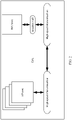
- a structure of a server may include an OS, firmware, and a CPU.
- the firmware may include boot firmware and IMU firmware.
- the boot firmware is, for example, unified extensible firmware interface (unified extensible firmware interface, UEFI) firmware or basic input/output system (Basic Input Output System, BIOS) firmware, and is shown as the UEFI firmware in the figure.
- the UEFI firmware may be configured to: when the OS is started, establish an advanced configuration and power interface (advanced configuration and power interface, ACPI) table, so that the OS can be normally started.
- ACPI advanced configuration and power interface
- the IMU firmware may be configured to implement the power management method provided in this application, that is, obtain a performance parameter of the CPU, and adjust a frequency and voltage of the CPU, to implement power management of the server.
- the CPU may include a plurality of independent cores (core), such as an application processor (application processor, AP) core for service processing, and a processor core configured to implement the power management method provided in the embodiments of this application.
- the processor core is referred to as an IMU core in the embodiments of this application.
- the UEFI firmware and the OS may run on the AP core, and the IMU firmware may run on the IMU core.
- the CPU may include only the AP core.
- the IMU firmware may run on the AP core, and the power management method provided in the embodiments of this application may also be implemented.
- FIG. 2 For a schematic diagram of a structure of a CPU that includes an AP core and an IMU core, refer to FIG. 2 .
- a plurality of AP cores are on a left side
- an IMU core is on a right side
- high-speed interconnection may be performed between the AP core and the IMU core.
- the IMU core independent of the CPU is configured to run IMU firmware to implement power management, data in the IMU core is relatively important.
- the AP core may be isolated from the IMU core by using a system isolation wall (system isolation wall, SIW), to implement unidirectional access between the AP core and the IMU core, that is, the IMU core can access data in the AP core, but the AP core cannot access the data in the IMU core.
- SIW system isolation wall
- a name of the IMU firmware is not limited to IMU. In another application, the IMU firmware may alternatively have another name.
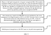
- a processing procedure of the method may include the following steps.
- Step 301 Obtain an intelligent management unit power management (intelligent management unit power management, IMU PM) execution notification before an operating system OS runs, where the IMU PM execution notification is sent by boot firmware after the boot firmware determines, before the OS runs, that PM is to be performed by an IMU, and the boot firmware is further configured to prevent, before the OS runs, the OS from performing operating system power management (operating system power management, OS PM).
- IMU PM intelligent management unit power management
- the IMU PM execution notification is used to notify the IMU firmware to perform IMU PM.
- the boot firmware may send the IMU PM execution notification
- the IMU firmware may obtain the IMU PM execution notification to enable the IMU PM.
- the boot firmware may first prevent the OS from performing OS PM.
- the boot firmware may determine, in the following manner, that PM is to be performed by the IMU firmware.
- PM setting options may be provided for a user by using a startup setting interface.
- the startup setting interface may be a UEFI setup interface or a BIOS interface.
- a server is powered on.
- the boot firmware When the boot firmware is started, a display screen outside the server may display a startup setting interface.
- the user may select IMU PM from PM setting options in the startup setting interface. Therefore, data of a configuration item that is PM setting in startup configuration items of the boot firmware is data used to indicate the IMU to perform PM.
- the boot firmware sends the IMU PM execution notification.
- the IMU PM execution notification may be in a plurality of forms. The following lists several of the plurality of forms for description.
- Form 1 The IMU PM execution notification is an IMU PM execution instruction.
- the processing in which the boot firmware sends the IMU PM execution notification may be as follows: The boot firmware sends the IMU PM execution instruction to the IMU firmware.
- the processing in which the IMU firmware obtains the IMU PM execution notification is as follows: The IMU firmware receives the
- Form 2 The IMU PM execution notification is first preset data in a preset storage address.
- the processing in which the boot firmware sends the IMU PM execution notification may be as follows:
- the boot firmware writes the first preset data into the preset storage address.
- the processing in which the IMU firmware obtains the IMU PM execution notification is as follows:
- the IMU firmware obtains the first preset data by polling the preset storage address.
- the preset storage address is a storage address that is preset by a person skilled in the art and that is used to store a PM execution notification, and the first preset data may be a binary numeral "1".
- the boot firmware may prevent, in a plurality of manners, the OS from performing OS PM.
- Manner 1 The boot firmware creates a first advanced configuration and power interface ACPI table, and reports the first ACPI table to the OS, where the first ACPI table does not include a performance status table, to prevent the OS from performing OS PM, and the performance status table is a performance support status PSS table or a continuous performance control CPC table.
- the ACPI table may include one of the PSS table and the CPC table. Both the PSS table and the CPC table can provide, for the OS, frequency adjustable values supported by a CPU. A difference is as follows:
- the PSS table provides frequency adjustable values that are of a plurality of different levels and that are supported by the CPU. For example, a frequency adjustable value of a P0 level is 2001 MHz, and a frequency adjustable value of a P2 level is 1900 MHz.
- the CPC table provides an upper limit and a lower limit of a frequency adjustable value supported by the CPU.
- the OS can adjust a frequency of the CPU based on the frequency adjustable values that are supported by the CPU and that are provided in the two tables.
- the boot firmware may not initialize a performance status table in the ACPI table, and therefore the OS cannot perform frequency adjustment on the CPU.
- Manner 2 creating a second ACPI table, and reporting the second ACPI table to the OS, where the second ACPI table includes a performance status table, and frequency adjustable values in the performance status table included in the second ACPI table are a same preset value, or a header of the performance status table included in the second ACPI table is a value with an undefined range, to prevent the OS from performing OS PM.
- the boot firmware may initialize a performance status table in the ACPI table, that is, initialize frequency adjustable values in the performance status table to a same preset value.
- a performance status table in the ACPI table that is, initialize frequency adjustable values in the performance status table to a same preset value.
- the performance status table is a PSS table
- frequency adjustable values of all levels in the performance status table may be all initialized to a same preset value.
- the frequency adjustable values of all the levels are all initialized to a frequency adjustable value of a P0 level, or the frequency adjustable values of all the levels may be all initialized to any same preset value, for example, 0 MHz.
- an upper limit and a lower limit of a frequency adjustable value of a CPU may be initialized to a same preset value.
- the upper limit of the frequency adjustable value is initialized to the lower limit of the frequency adjustable value
- the lower limit of the frequency adjustable value may be initialized to the upper limit of the frequency adjustable value
- the lower limit and the upper limit of the frequency adjustable value may be adjusted to any same preset value, for example, 0 MHz.
- the header of the performance status table may be initialized to the value with an undefined range, so that the OS cannot find a frequency adjustable value by using the header.
- the OS before the OS runs, the OS may be alternatively selected to perform PM.
- the boot firmware may perform the following operations: creating a third ACPI table, and sending the third ACPI table to the OS, where the third ACPI includes a performance status table, and a frequency adjustable value in the performance status table included in the third ACPI table is a preset frequency adjustable value supported by the CPU, so that the OS performs OS PM; and sending an IMU PM disable notification.
- the IMU firmware may further perform the following operations: obtaining the IMU PM disable notification, and disabling the IMU PM.
- the user may select OS PM from the PM setting options in the startup setting interface. Therefore, the data of the configuration item that is the PM setting in the startup configuration items of the boot firmware is data used to indicate the IMU to disable PM, or may be understood as data used to indicate the OS to perform PM.
- the boot firmware sends the IMU PM disable notification.
- the IMU PM disable notification may be in a plurality of forms. The following lists several of the plurality of forms for description.
- Form 1 The IMU PM disable notification is an IMU PM disable instruction.
- the processing in which the boot firmware sends the IMU PM disable notification may be as follows: The boot firmware sends the IMU PM disable instruction to the IMU firmware.
- the processing in which the IMU firmware obtains the IMU PM disable notification is as follows: The IMU firmware receives the IMU PM disable instruction sent by the boot firmware.
- Form 2 The IMU PM execution notification is second preset data in the preset storage address.
- the processing in which the boot firmware sends the IMU PM disable notification may be as follows:
- the boot firmware writes the second preset data into the preset storage address.
- the processing in which the IMU firmware obtains the IMU PM disable notification is as follows:
- the IMU firmware obtains the second preset data by polling the preset storage address.
- the preset storage address is a storage address that is preset by a person skilled in the art and that is used to store a PM execution notification, and the second preset data may be a binary numeral "0".
- the boot firmware may normally initialize a performance status table in the ACPI table, that is, initialize a frequency adjustable value in the performance status
- Step 302 After determining, based on the IMU PM execution notification, that power management is to be performed on the CPU by the IMU firmware, obtain a current performance parameter of the central processing unit CPU, where the performance parameter includes one or more of power consumption, a temperature, and usage of the CPU.
- the IMU firmware may obtain the performance parameter of the CPU, such as the power consumption, the temperature, and the usage.
- the IMU firmware may periodically obtain the power consumption of the CPU. For example, a period may be 0.5 second.
- the IMU may not immediately obtain the power consumption of the CPU, but the user determines whether frequency adjustment and voltage adjustment need to be performed on the CPU based on the power consumption of the CPU; and only when the user needs to perform frequency adjustment and voltage adjustment on the CPU based on the power consumption of the CPU, the IMU firmware periodically obtains the power consumption of the CPU.
- the user may enter code for limiting the power consumption of the CPU to an out-of-band management system, and therefore the out-of-band management system may send a power consumption limiting instruction to the IMU firmware.
- the power consumption limiting instruction may carry a power consumption threshold. After receiving the power consumption limiting instruction, the IMU obtains current power consumption of the CPU in real time.
- a temperature sensor may be installed in the CPU, the temperature sensor monitors the temperature of the CPU in real time, and the IMU firmware may periodically obtain a current temperature of the CPU from the temperature sensor. For example, a period may be 0.5 second.
- the temperature sensor may periodically monitor the temperature of the CPU, and only after the temperature reaches a temperature control threshold, the temperature sensor may send a current temperature of the CPU to the IMU firmware.
- a performance monitor unit (performance monitor unit, PMU) may be installed in each core of the CPU, and the PMU is configured to count a quantity of clocks in which the core in which the PMU is located is in a non-idle state. For each statistics period, the PMU counts, in the statistics period, clocks in which the core in which the PMU is located is in the non-idle state, and sends a quantity of clocks to the IMU firmware.
- the IMU firmware may divide the quantity of clocks in the non-idle state by a total quantity of clocks in the statistics period, to obtain usage of the corresponding core in the statistics period.
- a clock domain usage of all cores in the clock domain is added, and an obtained sum is divided by a quantity of cores in the clock domain, to obtain an average usage of the cores in the clock domain.
- only one clock domain may be set, that is, all cores are located in a same clock domain. In this case, usage of the CPU is average usage of the cores in the clock domain.
- a plurality of clock domains may be alternatively disposed. For example, each core corresponds to one clock domain, or each several cores correspond to one clock domain. In this case, usage of the CPU may be jointly represented by average usage of cores in these clock domains.
- Step 303 Perform power management on the CPU based on the performance parameter.
- the IMU firmware may adjust a frequency and voltage of the CPU based on different obtained performance parameters. The following separately describes adjusting the frequency and voltage of the CPU based on each obtained performance parameter.
- the frequency of the CPU is reduced, and the voltage of the CPU may be further reduced while the frequency is reduced.
- power and a voltage of an IO interface of the CPU may be further reduced. If the frequency of the CPU has been adjusted to a lowest adjustable value, some unused ports of cores of the CPU may be disabled. If the power consumption of the CPU is less than a preset multiple of the power consumption threshold, the frequency and voltage of the CPU are increased. The preset multiple is greater than 0 and less than 1, such as 0.95. In addition, power and a voltage of the IO interface of the CPU may be further increased.
- a high temperature alarm message is sent to the out-of-band management system. After receiving the high temperature alarm message, the out-of-band management system performs power-off protection on the CPU to prevent the CPU from being damaged due to an excessively high temperature. If the temperature of the CPU is less than the first temperature threshold and is greater than a second temperature threshold, the frequency of the CPU is reduced, and the voltage of the CPU may be further reduced while the frequency is reduced. In addition, power and a voltage of an IO interface of the CPU may be further reduced, and a fan speed may be further increased to improve heat dissipation.
- power domain statuses of cores in the CPU may be further adjusted, that is, power domains of some cores in an idle state are adjusted to be in a disabled state, in other words, these cores are disabled, so that the cores no longer run to generate heat.
- the temperature of the CPU is less than a third temperature threshold
- the frequency of the CPU may be increased, and the voltage of the CPU may be further increased while the frequency is increased.
- the third temperature threshold is less than the second temperature threshold.
- power domains of some cores in the CPU are previously adjusted to be in the disabled state for cooling, in this case, the power domains of these cores may be adjusted to be in an enabled state, in other words, these cores are re-enabled.
- the increasing or reducing the frequency of the CPU may be implemented by adjusting a phase-locked loop (phase locked loop, PLL) of a clock domain corresponding to each core in the CPU.
- PLL phase locked loop
- Mode 1 Fast-rise and slow-fall mode, that is, the frequency is fast increased and the frequency is slowly reduced. This mode can ensure performance of the CPU.
- Mode 2 Slow-rise and fast-fall mode, that is, the frequency is slowly increased and the frequency is fast reduced. This mode can effectively reduce power consumption of the CPU.
- how to adjust the frequency and voltage of the CPU may be comprehensively determined based on all performance parameters of the CPU.
- processing may be as follows: entering the performance parameters and a current frequency and voltage of the CPU into a pre-trained feature extraction model, to obtain a to-be-classified feature data; entering the to-be-classified feature data into a pre-trained classifier model to obtain a current service type of the CPU; determining, based on a pre-stored correspondence between a service type and a configuration adjustment policy, a configuration adjustment policy corresponding to the current service type of the CPU, where the configuration adjustment policy includes at least a to-be-used frequency and a to-be-used voltage of the CPU; and respectively adjusting the frequency and voltage of the CPU to the to-be-used frequency and the to-be-used voltage.
- the feature extraction model may be a long short-term memory (long short-term memory, LSTM) autoencoder model, a recurrent neural network (recurrent neural network, RNN) model, or the like
- the classifier model may be a k-nearest neighbor (k-nearest neighbor, KNN) classification model, a multilayer perceptron (multi-layer perception, MLP) classification model, or the like.
- a person skilled in the art may pre-establish a feature extraction model and a classifier model, and train the feature extraction model and the classifier model.
- the two models may be simultaneously trained.
- a person skilled in the art may collect a plenty of CPU runtime performance parameters and CPU voltages and frequencies from the server as input samples, that is, each group of input samples includes at least a CPU runtime performance parameter and a CPU voltage and frequency.
- service classification may be manually performed on the input samples. For example, the input samples may be classified into 10 service types. Service types corresponding to each group of input samples are output samples. In this way, the output samples corresponding to each group of input samples may form one group of training samples.
- the feature extraction model and the classifier model are trained by using a plenty of training samples, and parameters of the feature extraction model and the classifier model are continuously adjusted, so that accuracy of the feature extraction model and the classifier model are higher. Finally, a trained feature extraction model and classifier model may be obtained.
- a person skilled in the art may perform energy efficiency scoring on CPU runtime performance parameters and CPU voltages and frequencies that correspond to the service type, and use a CPU voltage and frequency in a group with a highest energy efficiency score as a configuration adjustment policy corresponding to the service type. Then, each service type and the corresponding configuration adjustment policy are correspondingly stored. In this way, the configuration adjustment policy may be a to-be-used frequency and a to-be-used voltage of the CPU in the corresponding service type.
- the IMU firmware may enter periodically obtained performance parameters of the CPU and the voltage and frequency of the CPU into the pre-trained feature extraction model and classifier model to obtain the corresponding target service type; then, query the correspondence between a service type and a configuration adjustment policy to obtain the configuration adjustment policy corresponding to the target service type, where the configuration adjustment policy includes the to-be-used frequency and the to-be-used voltage of the CPU; and then, may adjust the frequency of the CPU to the to-be-used frequency, and adjust the voltage of the CPU to the to-be-used voltage.
- the IMU firmware may obtain the IMU PM execution notification, to enable the IMU PM; and directly obtain the current performance parameter of the CPU, and adjust the frequency and voltage of the CPU based on the obtained performance parameter, to implement power management.
- the OS does not need to obtain the performance parameter and then notify the IMU firmware to adjust the frequency and voltage of the CPU. Therefore, interaction procedures are reduced, so that the frequency and the voltage are more efficiently adjusted.
- a processing procedure of the method may include the following steps.
- Step 401 In a running process of an OS, receive a first notification message that is sent by an out-of-band management system and that is used to notify the IMU firmware to perform IMU PM.
- the out-of-band management system may be a baseboard management controller (baseboard management controller, BMC).
- BMC baseboard management controller
- the out-of-band management system may be another CPU, namely, a CPU 1, in the server.
- the out-of-band management system may be alternatively a processor core in a CPU.
- the user may enter code for enabling the IMU PM into the out-of-band management system, and therefore the out-of-band management system sends the first notification message to the IMU firmware by using an intelligent platform management interface (intelligent platform management interface, IPMI), so that the IMU firmware performs IMU PM after receiving the first notification message.
- IPMI intelligent platform management interface
- Step 402 Interact with the OS based on the first notification message, so that the OS is no longer responsible for the power management.
- Manner 1 if receiving a first power management request sent by the OS, returning a preset message to the OS instead of performing power management according to the first power management request, so that the OS is no longer responsible for the power management.
- the first power management request may be a request for indicating, by the OS, the IMU to perform frequency adjustment on the CPU.
- the IMU firmware does not perform the frequency adjustment operation corresponding to the first power management request, but performs IMU PM of the IMU firmware.
- the IMU firmware may return the preset message to the OS.
- the preset message may be an execution success notification message, to deceive the OS, so that the OS considers that the OS is responsible for the PM, but the IMU firmware is actually responsible for the PM.
- Manner 2 obtaining a fourth advanced configuration and power interface ACPI table, and updating the fourth ACPI table to obtain a fourth updated ACPI table; sending a fourth ACPI table update message to the OS, where the fourth ACPI table update message is used to indicate the OS to obtain the fourth updated ACPI table, so that the OS disables OS PM based on the fourth updated ACPI table.
- an ACPI table may be updated, so that the OS cannot perform power management based on the ACPI table.
- the IMU firmware may update the ACPI table by using a plurality of methods. The following lists several of the plurality of methods for description.
- Method 1 removing a performance status table included in the fourth ACPI table, where the performance status table is a PSS table or a CPC table.
- the IMU firmware may obtain the ACPI table (namely, the fourth ACPI table) from a memory, remove a performance status table from the ACPI table, and then store an ACPI table obtained after the removal in an original storage address.
- the OS cannot obtain the performance status table through parsing, and therefore cannot perform OS PM.
- Method 2 adjusting, to a same preset value, frequency adjustable values in a performance status table included in the fourth ACPI table.
- the frequency adjustable values in the performance status table are adjusted to the same preset value.
- the performance status table is a PSS table
- frequency adjustable values of all levels in the performance status table may be all adjusted to a same preset value.
- the frequency adjustable values of all the levels are all adjusted to a frequency adjustable value of a P0 level, or the frequency adjustable values of all the levels may be all adjusted to any same preset value, for example, 0 MHz.
- the performance status table is a CPC table
- an upper limit and a lower limit of a frequency adjustable value of the CPU may be adjusted to a same preset value.
- the upper limit of the frequency adjustable value is adjusted to the lower limit of the frequency adjustable value
- the lower limit of the frequency adjustable value may be adjusted to the upper limit of the frequency adjustable value
- the lower limit and the upper limit of the frequency adjustable value may be adjusted to any same preset value, for example, 0 MHz.
- Method 3 modifying, into a value with an undefined range, a header of a performance status table included in the fourth ACPI table.
- the header of the performance status table may be modified into the value with an undefined range, so that the OS cannot find a frequency adjustable value by using the header.
- the OS PM in the running process of the OS, may be alternatively selected by using the out-of-band management system.
- the IMU PM may perform the following operations: in the running process of the operating system OS, receiving a second notification message that is sent by the out-of-band management system and that is used to notify the IMU firmware to enable the OS PM; and if the OS is currently responsible for the power management, skipping processing the second notification message; or if the OS is not currently responsible for the power management, interacting with the OS based on the second notification message, so that the OS is responsible for the power management.
- the user may enter code for enabling the IMU PM to the out-of-band management system, and therefore the out-of-band management system may send the second notification message to the IMU firmware by using the IPMI. If current PM is the OS PM, the second notification message may not be processed. If current PM is the IMU PM, after the second notification message is received, the IMU PM needs to be disabled, and the OS is enabled to be responsible for the PM, in other words, the OS PM is enabled.
- the IMU firmware after receiving the second notification message, after receiving a second power management request sent by the OS, the IMU firmware performs the second power management.
- the IMU firmware after receiving the second notification message, obtains a fifth ACPI table, and updates the fifth ACPI table to obtain a fifth updated ACPI table; and sends a fifth ACPI table update message to the OS, where the fifth ACPI table update message is used to indicate the OS to obtain the fifth updated ACPI table, so that the OS can enable the OS PM based on the fifth updated ACPI table.
- the ACPI table may be updated in the following method: if the fifth ACPI table does not include a performance status table, adding a performance status table to the fifth ACPI table; or if the fifth ACPI table includes a performance status table, adjusting, to a preset frequency adjustable value supported by the CPU, a frequency adjustable value in the performance status table included in the fifth ACPI table.
- the ACPI table (namely, the fifth ACPI table) may be obtained from the memory, and a normal performance status table may be added to the ACPI table.
- a frequency adjustable value in the performance status table may be adjusted to a preset frequency adjustable value supported by the CPU.
- a header of the performance status table may be adjusted to a header of a normal frequency adjustable value. After the ACPI table is updated, an updated ACPI table is stored in an original storage address.
- the following describes a process in which the IMU firmware sends an ACPI table update message to the OS.
- the IMU firmware When acknowledging that a Mailbox (mailbox) with the OS is empty, the IMU firmware writes an ACPI table update message into the Mailbox, and simultaneously generates notify interrupt (Notify Interrupt) and feds back the notify interrupt to the OS.
- notify Interrupt When receiving the Notify Interrupt or obtains the Notify Interrupt through polling, the OS processes the ACPI table update message in the Mailbox, generates doorbell (Doorbell) interrupt and sends the doorbell interrupt to the IMU firmware, and clears the Notify Interrupt.
- the IMU firmware After receiving the Doorbell interrupt returned by the OS, the IMU firmware acknowledges the Doorbell interrupt of the OS, and clears the Doorbell interrupt.
- this embodiment of this application further provides a data structure of a communication message sent between the IUM firmware and the OS.
- the communication message may be the ACPI table update message.
- the data structure is shown in the following Table 1.
- Step 403 After determining, based on the first notification message, that power management is to be performed on the CPU by the IMU firmware, obtain a current performance parameter of the central processing unit CPU, where the performance parameter includes one or more of power consumption, a temperature, and usage of the CPU.
- the IMU firmware may obtain the performance parameter of the CPU, such as the power consumption, the temperature, and the usage.
- the IMU firmware may periodically obtain the power consumption of the CPU. For example, a period may be 0.5 second.
- the IMU may not immediately obtain the power consumption of the CPU, but the user determines whether frequency adjustment and voltage adjustment need to be performed on the CPU based on the power consumption of the CPU; and only when the user needs to perform frequency adjustment and voltage adjustment on the CPU based on the power consumption of the CPU, the IMU firmware periodically obtains the power consumption of the CPU.
- the user may enter code for limiting the power consumption of the CPU to the out-of-band management system, and the out-of-band management system may send a power consumption limiting instruction to the IMU firmware.
- the power consumption limiting instruction may carry a power consumption threshold. After receiving the power consumption limiting instruction, the IMU obtains current power consumption of the CPU in real time.
- a temperature sensor may be installed in the CPU, the temperature sensor monitors the temperature of the CPU in real time, and the IMU firmware may periodically obtain a current temperature of the CPU from the temperature sensor. For example, a period may be 0.5 second.
- the temperature sensor may periodically monitor the temperature of the CPU, and only after the temperature reaches a temperature control threshold, the temperature sensor may send a current temperature of the CPU to the IMU firmware.
- a performance monitor unit (performance monitor unit, PMU) may be installed in each core of the CPU, and the PMU is configured to count a quantity of clocks in which the core in which the PMU is located is in a non-idle state. For each statistics period, the PMU counts, in the statistics period, clocks in which the core in which the PMU is located is in the non-idle state, and sends a quantity of clocks to the IMU firmware.
- the IMU firmware may divide the quantity of clocks in the non-idle state by a total quantity of clocks in the statistics period, to obtain usage of the corresponding core in the statistics period.
- a clock domain usage of all cores in the clock domain is added, and an obtained sum is divided by a quantity of cores in the clock domain, to obtain an average usage of the cores in the clock domain.
- only one clock domain may be set, that is, all cores are located in a same clock domain. In this case, usage of the CPU is average usage of the cores in the clock domain.
- a plurality of clock domains may be alternatively disposed. For example, each core corresponds to one clock domain, or each several cores correspond to one clock domain. In this case, usage of the CPU may be jointly represented by average usage of cores in these clock domains.
- Step 404 Perform power management on the CPU based on the performance parameter.
- the IMU firmware may adjust a frequency and voltage of the CPU based on different obtained performance parameters. The following separately describes adjusting the frequency and voltage of the CPU based on each obtained performance parameter.
- the frequency of the CPU is reduced, and the voltage of the CPU may be further reduced while the frequency is reduced.
- power and a voltage of an IO interface of the CPU may be further reduced. If the frequency of the CPU has been adjusted to a lowest adjustable value, some unused ports of cores of the CPU may be disabled. If the power consumption of the CPU is less than a preset multiple of the power consumption threshold, the frequency and voltage of the CPU are increased. The preset multiple is greater than 0 and less than 1, such as 0.95. In addition, power and a voltage of the IO interface of the CPU may be further increased.
- a high temperature alarm message is sent to the out-of-band management system. After receiving the high temperature alarm message, the out-of-band management system performs power-off protection on the CPU to prevent the CPU from being damaged due to an excessively high temperature. If the temperature of the CPU is less than the first temperature threshold and is greater than a second temperature threshold, the frequency of the CPU is reduced, and the voltage of the CPU may be further reduced while the frequency is reduced. In addition, power and a voltage of an IO interface of the CPU may be further reduced, and a fan speed may be further increased to improve heat dissipation.
- power domain statuses of cores in the CPU may be further adjusted, that is, power domains of some cores in an idle state are adjusted to be in a disabled state, in other words, these cores are disabled, so that the cores no longer run to generate heat.
- the temperature of the CPU is less than a third temperature threshold
- the frequency of the CPU may be increased, and the voltage of the CPU may be further increased while the frequency is increased.
- the third temperature threshold is less than the second temperature threshold.
- power domains of some cores in the CPU are previously adjusted to be in the disabled state for cooling, in this case, the power domains of these cores may be adjusted to be in an enabled state, in other words, these cores are re-enabled.
- the increasing or reducing the frequency of the CPU may be implemented by adjusting a phase-locked loop (phase locked loop, PLL) of a clock domain corresponding to each core in the CPU.
- PLL phase locked loop
- Mode 1 Fast-rise and slow-fall mode, that is, the frequency is fast increased and the frequency is slowly reduced. This mode can ensure performance of the CPU.
- Mode 2 Slow-rise and fast-fall mode, that is, the frequency is slowly increased and the frequency is fast reduced. This mode can effectively reduce power consumption of the CPU.
- how to adjust the frequency and voltage of the CPU may be comprehensively determined based on all performance parameters of the CPU.
- processing may be as follows: entering the performance parameters and a current frequency and voltage of the CPU into a pre-trained feature extraction model, to obtain a to-be-classified feature data; entering the to-be-classified feature data into a pre-trained classifier model to obtain a current service type of the CPU; determining, based on a pre-stored correspondence between a service type and a configuration adjustment policy, a configuration adjustment policy corresponding to the current service type of the CPU, where the configuration adjustment policy includes at least a to-be-used frequency and a to-be-used voltage of the CPU; and respectively adjusting the frequency and voltage of the CPU to the to-be-used frequency and the to-be-used voltage.
- the feature extraction model may be a long short-term memory (long short-term memory, LSTM) autoencoder model, a recurrent neural network (recurrent neural network, RNN) model, or the like
- the classifier model may be a k-nearest neighbor (k-nearest neighbor, KNN) classification model, a multilayer perceptron (multi-layer perception, MLP) classification model, or the like.
- a person skilled in the art may pre-establish a feature extraction model and a classifier model, and train the feature extraction model and the classifier model.
- the two models may be simultaneously trained.
- a person skilled in the art may collect a plenty of CPU runtime performance parameters and CPU voltages and frequencies from the server as input samples, that is, each group of input samples includes at least a CPU runtime performance parameter and a CPU voltage and frequency.
- service classification may be manually performed on the input samples. For example, the input samples may be classified into 10 service types.
- a service type corresponding to each group of input samples is an output sample. In this way, the output samples corresponding to each group of input samples may form one group of training samples.
- the feature extraction model and the classifier model are trained by using a plenty of training samples, and parameters of the feature extraction model and the classifier model are continuously adjusted, so that accuracy of the feature extraction model and the classifier model are higher. Finally, a trained feature extraction model and classifier model may be obtained.
- a person skilled in the art may perform energy efficiency scoring on CPU runtime performance parameters and CPU voltages and frequencies that correspond to the service type, and use a CPU voltage and frequency in a group with a highest energy efficiency score as a configuration adjustment policy corresponding to the service type. Then, each service type and the corresponding configuration adjustment policy are correspondingly stored. In this way, the configuration adjustment policy may be a to-be-used frequency and a to-be-used voltage of the CPU in the corresponding service type.
- the IMU firmware may enter periodically obtained performance parameters of the CPU and the voltage and frequency of the CPU into the pre-trained feature extraction model and classifier model to obtain the corresponding target service type; then, query the correspondence between a service type and a configuration adjustment policy to obtain the configuration adjustment policy corresponding to the target service type, where the configuration adjustment policy includes the to-be-used frequency and the to-be-used voltage of the CPU; and then, may adjust the frequency of the CPU to the to-be-used frequency, and adjust the voltage of the CPU to the to-be-used voltage.
- the IMU firmware may obtain the IMU PM execution notification, to enable the IMU PM; and directly obtain the current performance parameter of the CPU, and adjust the frequency and voltage of the CPU based on the obtained performance parameter, to implement power management.
- the OS does not need to obtain the performance parameter and then notify the IMU firmware to adjust the frequency and voltage of the CPU. Therefore, interaction procedures are reduced, so that the frequency and the voltage are more efficiently adjusted.
- the device may include a CPU 610 and a storage 620, the storage 620 stores a plurality of program instructions respectively corresponding to boot firmware, an OS, and IMU firmware, the plurality of program instructions are read and executed by the CPU to implement functions of the boot firmware, the OS, and the IMU firmware.
- the IMU firmware may be configured to perform a power management method.
- the CPU 610 may be the CPU in FIG. 2 . It may be learned that the CPU includes an IMU core and an AP core. To ensure security of data in the IMU core, the IMU core may be isolated from the AP core by using a system isolation wall SIW. A function of the IMU firmware may be processed by the IMU core.
Landscapes
- Engineering & Computer Science (AREA)
- Theoretical Computer Science (AREA)
- General Engineering & Computer Science (AREA)
- Physics & Mathematics (AREA)
- General Physics & Mathematics (AREA)
- Software Systems (AREA)
- Computer Hardware Design (AREA)
- Computing Systems (AREA)
- Human Computer Interaction (AREA)
- Computer Security & Cryptography (AREA)
- Power Sources (AREA)
Applications Claiming Priority (2)
| Application Number | Priority Date | Filing Date | Title |
|---|---|---|---|
| CN201911007882.3A CN112698712B (zh) | 2019-10-22 | 2019-10-22 | 能耗管理的方法和设备 |
| PCT/CN2020/122459 WO2021078144A1 (zh) | 2019-10-22 | 2020-10-21 | 能耗管理的方法和设备 |
Publications (3)
| Publication Number | Publication Date |
|---|---|
| EP4033332A1 true EP4033332A1 (de) | 2022-07-27 |
| EP4033332A4 EP4033332A4 (de) | 2022-12-07 |
| EP4033332B1 EP4033332B1 (de) | 2025-02-19 |
Family
ID=75504971
Family Applications (1)
| Application Number | Title | Priority Date | Filing Date |
|---|---|---|---|
| EP20878976.8A Active EP4033332B1 (de) | 2019-10-22 | 2020-10-21 | Leistungsverwaltungsverfahren und -vorrichtung |
Country Status (4)
| Country | Link |
|---|---|
| US (1) | US12321215B2 (de) |
| EP (1) | EP4033332B1 (de) |
| CN (1) | CN112698712B (de) |
| WO (1) | WO2021078144A1 (de) |
Families Citing this family (5)
| Publication number | Priority date | Publication date | Assignee | Title |
|---|---|---|---|---|
| CN113625861B (zh) * | 2021-08-27 | 2024-04-19 | 深圳供电局有限公司 | 一种功耗节约方法及系统 |
| CN116301095B (zh) * | 2022-12-23 | 2024-03-19 | 摩尔线程智能科技(北京)有限责任公司 | Gpu的温度控制方法、装置、设备、介质和程序产品 |
| CN115981448A (zh) * | 2022-12-23 | 2023-04-18 | 摩尔线程智能科技(北京)有限责任公司 | Gpu的功耗控制方法、装置、设备、介质和程序产品 |
| WO2025097344A1 (en) * | 2023-11-08 | 2025-05-15 | Telefonaktiebolaget Lm Ericsson (Publ) | Methods, devices and medium for power management |
| US20260086615A1 (en) * | 2024-09-26 | 2026-03-26 | Apple Inc. | Power State Selection Based on Circuit Activity |
Family Cites Families (13)
| Publication number | Priority date | Publication date | Assignee | Title |
|---|---|---|---|---|
| US7032116B2 (en) * | 2001-12-21 | 2006-04-18 | Intel Corporation | Thermal management for computer systems running legacy or thermal management operating systems |
| US7089430B2 (en) * | 2001-12-21 | 2006-08-08 | Intel Corporation | Managing multiple processor performance states |
| US7577860B2 (en) * | 2006-01-09 | 2009-08-18 | Microsoft Corporation | Processor specific BIOS interface for power management |
| CN101093446B (zh) * | 2006-06-21 | 2011-06-22 | 鸿富锦精密工业(深圳)有限公司 | 操作系统引导装置、方法及其应用的电脑系统 |
| US8315746B2 (en) * | 2008-05-30 | 2012-11-20 | Apple Inc. | Thermal management techniques in an electronic device |
| CN101477403B (zh) * | 2009-01-22 | 2011-10-05 | 浪潮电子信息产业股份有限公司 | 一种系统功耗自动控制方法 |
| US9477627B2 (en) * | 2012-12-26 | 2016-10-25 | Intel Corporation | Interconnect to communicate information uni-directionally |
| CN103488532A (zh) * | 2013-09-02 | 2014-01-01 | 华为技术有限公司 | 一种调整处理器频率的方法和设备 |
| US9575540B1 (en) * | 2015-07-31 | 2017-02-21 | Hon Hai Precision Industry Co., Ltd. | Power consumption management device, system and method thereof |
| CN105677000B (zh) * | 2016-02-14 | 2018-10-19 | 华为技术有限公司 | 动态电压频率调整的系统及方法 |
| CN108334405A (zh) * | 2017-01-20 | 2018-07-27 | 阿里巴巴集团控股有限公司 | 频率异构cpu,频率异构实现方法、装置及任务调度方法 |
| CN108803860A (zh) * | 2018-06-26 | 2018-11-13 | 联想(北京)有限公司 | 一种功耗调节方法及电子设备 |
| US11307907B2 (en) * | 2020-02-03 | 2022-04-19 | Dell Products L.P. | Information handling system and method to automatically synchronize operating system and boot firmware languages |
-
2019
- 2019-10-22 CN CN201911007882.3A patent/CN112698712B/zh active Active
-
2020
- 2020-10-21 EP EP20878976.8A patent/EP4033332B1/de active Active
- 2020-10-21 WO PCT/CN2020/122459 patent/WO2021078144A1/zh not_active Ceased
-
2022
- 2022-04-22 US US17/727,686 patent/US12321215B2/en active Active
Also Published As
| Publication number | Publication date |
|---|---|
| CN112698712A (zh) | 2021-04-23 |
| CN112698712B (zh) | 2022-12-06 |
| US12321215B2 (en) | 2025-06-03 |
| US20220244772A1 (en) | 2022-08-04 |
| EP4033332B1 (de) | 2025-02-19 |
| EP4033332A4 (de) | 2022-12-07 |
| WO2021078144A1 (zh) | 2021-04-29 |
Similar Documents
| Publication | Publication Date | Title |
|---|---|---|
| US12321215B2 (en) | Power management method and device | |
| US8156353B2 (en) | Techniques for communications power management based on system states | |
| JP5707321B2 (ja) | スリーププロセッサ | |
| US8250382B2 (en) | Power control of servers using advanced configuration and power interface (ACPI) states | |
| US9170632B2 (en) | Providing wakeup logic to awaken an electronic device from a lower power mode | |
| US20120110360A1 (en) | Application-specific power management | |
| US7051236B2 (en) | Wirelessly network-connected, battery-powered information handling system featuring prevention of data corruption after wake-up by a network event | |
| EP4475603A1 (de) | Verfahren und vorrichtung zur schlafsteuerung einer netzwerkvorrichtung sowie netzwerkvorrichtung und speichermedium | |
| JP2010165349A (ja) | 電力管理のためのアイドル期間報告 | |
| TW201203936A (en) | Method and system for managing network power policy and configuration of data center bridging | |
| US8832483B1 (en) | System-on-chip with power-save mode processor | |
| CN115756616B (zh) | 基本输入输出系统bios配置项的配置方法及服务器 | |
| EP4239452A1 (de) | Verfahren und vorrichtung zur verwaltung eines netzwerkchips, kommunikationsvorrichtung und speichermedium | |
| CN115004640B (zh) | 一种设备功耗管理系统、方法、设备和存储介质 | |
| US7636861B2 (en) | Bus technique for controlling power states of blades in a blade enclosure | |
| TWI677253B (zh) | 信標信號處理裝置 | |
| CN100508468C (zh) | 分布式节点动态管理数据自适应交换方法 | |
| EP3563519B1 (de) | Technologien für ein lokales netzwerkleistungsverwaltungsprotokoll | |
| CN119520180B (zh) | 一种远程控制服务终端开关机方法、装置及存储介质 | |
| CN110209262A (zh) | 一种电子设备及处理方法 | |
| WO2020018113A1 (en) | Assigning power sources | |
| WO2025148361A1 (zh) | 云桌面休眠方法、装置、设备以及计算机可读存储介质 | |
| JP7040034B2 (ja) | 情報処理装置及び画像形成装置 | |
| US9698781B1 (en) | Dynamic clock gating frequency scaling | |
| CN117631733A (zh) | 一种电源电压的动态调节方法、嵌入式控制器以及系统 |
Legal Events
| Date | Code | Title | Description |
|---|---|---|---|
| STAA | Information on the status of an ep patent application or granted ep patent |
Free format text: STATUS: THE INTERNATIONAL PUBLICATION HAS BEEN MADE |
|
| PUAI | Public reference made under article 153(3) epc to a published international application that has entered the european phase |
Free format text: ORIGINAL CODE: 0009012 |
|
| STAA | Information on the status of an ep patent application or granted ep patent |
Free format text: STATUS: REQUEST FOR EXAMINATION WAS MADE |
|
| 17P | Request for examination filed |
Effective date: 20220422 |
|
| AK | Designated contracting states |
Kind code of ref document: A1 Designated state(s): AL AT BE BG CH CY CZ DE DK EE ES FI FR GB GR HR HU IE IS IT LI LT LU LV MC MK MT NL NO PL PT RO RS SE SI SK SM TR |
|
| REG | Reference to a national code |
Ref country code: DE Ref legal event code: R079 Free format text: PREVIOUS MAIN CLASS: G06F0001324000 Ipc: G06F0001323400 Ref country code: DE Ref legal event code: R079 Ref document number: 602020046532 Country of ref document: DE Free format text: PREVIOUS MAIN CLASS: G06F0001324000 Ipc: G06F0001323400 |
|
| A4 | Supplementary search report drawn up and despatched |
Effective date: 20221104 |
|
| RIC1 | Information provided on ipc code assigned before grant |
Ipc: G06F 1/3287 20190101ALI20221028BHEP Ipc: G06F 1/3215 20190101ALI20221028BHEP Ipc: G06F 1/26 20060101ALI20221028BHEP Ipc: G06F 1/20 20060101ALI20221028BHEP Ipc: G06F 1/3296 20190101ALI20221028BHEP Ipc: G06F 1/324 20190101ALI20221028BHEP Ipc: G06F 1/3234 20190101AFI20221028BHEP |
|
| DAV | Request for validation of the european patent (deleted) | ||
| DAX | Request for extension of the european patent (deleted) | ||
| STAA | Information on the status of an ep patent application or granted ep patent |
Free format text: STATUS: EXAMINATION IS IN PROGRESS |
|
| 17Q | First examination report despatched |
Effective date: 20240131 |
|
| GRAP | Despatch of communication of intention to grant a patent |
Free format text: ORIGINAL CODE: EPIDOSNIGR1 |
|
| STAA | Information on the status of an ep patent application or granted ep patent |
Free format text: STATUS: GRANT OF PATENT IS INTENDED |
|
| RIC1 | Information provided on ipc code assigned before grant |
Ipc: G06F 9/4401 20180101ALI20241011BHEP Ipc: G06F 1/3287 20190101ALI20241011BHEP Ipc: G06F 1/3215 20190101ALI20241011BHEP Ipc: G06F 1/26 20060101ALI20241011BHEP Ipc: G06F 1/20 20060101ALI20241011BHEP Ipc: G06F 1/3296 20190101ALI20241011BHEP Ipc: G06F 1/324 20190101ALI20241011BHEP Ipc: G06F 1/3234 20190101AFI20241011BHEP |
|
| INTG | Intention to grant announced |
Effective date: 20241028 |
|
| GRAS | Grant fee paid |
Free format text: ORIGINAL CODE: EPIDOSNIGR3 |
|
| GRAA | (expected) grant |
Free format text: ORIGINAL CODE: 0009210 |
|
| STAA | Information on the status of an ep patent application or granted ep patent |
Free format text: STATUS: THE PATENT HAS BEEN GRANTED |
|
| P01 | Opt-out of the competence of the unified patent court (upc) registered |
Free format text: CASE NUMBER: APP_703/2025 Effective date: 20250108 |
|
| AK | Designated contracting states |
Kind code of ref document: B1 Designated state(s): AL AT BE BG CH CY CZ DE DK EE ES FI FR GB GR HR HU IE IS IT LI LT LU LV MC MK MT NL NO PL PT RO RS SE SI SK SM TR |
|
| REG | Reference to a national code |
Ref country code: GB Ref legal event code: FG4D |
|
| REG | Reference to a national code |
Ref country code: CH Ref legal event code: EP |
|
| REG | Reference to a national code |
Ref country code: IE Ref legal event code: FG4D |
|
| REG | Reference to a national code |
Ref country code: DE Ref legal event code: R096 Ref document number: 602020046532 Country of ref document: DE |
|
| REG | Reference to a national code |
Ref country code: NL Ref legal event code: MP Effective date: 20250219 |
|
| PG25 | Lapsed in a contracting state [announced via postgrant information from national office to epo] |
Ref country code: RS Free format text: LAPSE BECAUSE OF FAILURE TO SUBMIT A TRANSLATION OF THE DESCRIPTION OR TO PAY THE FEE WITHIN THE PRESCRIBED TIME-LIMIT Effective date: 20250519 |
|
| PG25 | Lapsed in a contracting state [announced via postgrant information from national office to epo] |
Ref country code: FI Free format text: LAPSE BECAUSE OF FAILURE TO SUBMIT A TRANSLATION OF THE DESCRIPTION OR TO PAY THE FEE WITHIN THE PRESCRIBED TIME-LIMIT Effective date: 20250219 |
|
| PG25 | Lapsed in a contracting state [announced via postgrant information from national office to epo] |
Ref country code: PL Free format text: LAPSE BECAUSE OF FAILURE TO SUBMIT A TRANSLATION OF THE DESCRIPTION OR TO PAY THE FEE WITHIN THE PRESCRIBED TIME-LIMIT Effective date: 20250219 |
|
| PG25 | Lapsed in a contracting state [announced via postgrant information from national office to epo] |
Ref country code: ES Free format text: LAPSE BECAUSE OF FAILURE TO SUBMIT A TRANSLATION OF THE DESCRIPTION OR TO PAY THE FEE WITHIN THE PRESCRIBED TIME-LIMIT Effective date: 20250219 |
|
| REG | Reference to a national code |
Ref country code: LT Ref legal event code: MG9D |
|
| PG25 | Lapsed in a contracting state [announced via postgrant information from national office to epo] |
Ref country code: IS Free format text: LAPSE BECAUSE OF FAILURE TO SUBMIT A TRANSLATION OF THE DESCRIPTION OR TO PAY THE FEE WITHIN THE PRESCRIBED TIME-LIMIT Effective date: 20250619 Ref country code: NO Free format text: LAPSE BECAUSE OF FAILURE TO SUBMIT A TRANSLATION OF THE DESCRIPTION OR TO PAY THE FEE WITHIN THE PRESCRIBED TIME-LIMIT Effective date: 20250519 |
|
| PG25 | Lapsed in a contracting state [announced via postgrant information from national office to epo] |
Ref country code: NL Free format text: LAPSE BECAUSE OF FAILURE TO SUBMIT A TRANSLATION OF THE DESCRIPTION OR TO PAY THE FEE WITHIN THE PRESCRIBED TIME-LIMIT Effective date: 20250219 |
|
| PG25 | Lapsed in a contracting state [announced via postgrant information from national office to epo] |
Ref country code: HR Free format text: LAPSE BECAUSE OF FAILURE TO SUBMIT A TRANSLATION OF THE DESCRIPTION OR TO PAY THE FEE WITHIN THE PRESCRIBED TIME-LIMIT Effective date: 20250219 |
|
| PG25 | Lapsed in a contracting state [announced via postgrant information from national office to epo] |
Ref country code: PT Free format text: LAPSE BECAUSE OF FAILURE TO SUBMIT A TRANSLATION OF THE DESCRIPTION OR TO PAY THE FEE WITHIN THE PRESCRIBED TIME-LIMIT Effective date: 20250620 Ref country code: LV Free format text: LAPSE BECAUSE OF FAILURE TO SUBMIT A TRANSLATION OF THE DESCRIPTION OR TO PAY THE FEE WITHIN THE PRESCRIBED TIME-LIMIT Effective date: 20250219 |
|
| PG25 | Lapsed in a contracting state [announced via postgrant information from national office to epo] |
Ref country code: GR Free format text: LAPSE BECAUSE OF FAILURE TO SUBMIT A TRANSLATION OF THE DESCRIPTION OR TO PAY THE FEE WITHIN THE PRESCRIBED TIME-LIMIT Effective date: 20250520 Ref country code: BG Free format text: LAPSE BECAUSE OF FAILURE TO SUBMIT A TRANSLATION OF THE DESCRIPTION OR TO PAY THE FEE WITHIN THE PRESCRIBED TIME-LIMIT Effective date: 20250219 |
|
| REG | Reference to a national code |
Ref country code: AT Ref legal event code: MK05 Ref document number: 1768902 Country of ref document: AT Kind code of ref document: T Effective date: 20250219 |
|
| PG25 | Lapsed in a contracting state [announced via postgrant information from national office to epo] |
Ref country code: SE Free format text: LAPSE BECAUSE OF FAILURE TO SUBMIT A TRANSLATION OF THE DESCRIPTION OR TO PAY THE FEE WITHIN THE PRESCRIBED TIME-LIMIT Effective date: 20250219 |
|
| PG25 | Lapsed in a contracting state [announced via postgrant information from national office to epo] |
Ref country code: SM Free format text: LAPSE BECAUSE OF FAILURE TO SUBMIT A TRANSLATION OF THE DESCRIPTION OR TO PAY THE FEE WITHIN THE PRESCRIBED TIME-LIMIT Effective date: 20250219 |
|
| PG25 | Lapsed in a contracting state [announced via postgrant information from national office to epo] |
Ref country code: DK Free format text: LAPSE BECAUSE OF FAILURE TO SUBMIT A TRANSLATION OF THE DESCRIPTION OR TO PAY THE FEE WITHIN THE PRESCRIBED TIME-LIMIT Effective date: 20250219 |
|
| PG25 | Lapsed in a contracting state [announced via postgrant information from national office to epo] |
Ref country code: IT Free format text: LAPSE BECAUSE OF FAILURE TO SUBMIT A TRANSLATION OF THE DESCRIPTION OR TO PAY THE FEE WITHIN THE PRESCRIBED TIME-LIMIT Effective date: 20250219 |
|
| PGFP | Annual fee paid to national office [announced via postgrant information from national office to epo] |
Ref country code: GB Payment date: 20250904 Year of fee payment: 6 |
|
| PG25 | Lapsed in a contracting state [announced via postgrant information from national office to epo] |
Ref country code: AT Free format text: LAPSE BECAUSE OF FAILURE TO SUBMIT A TRANSLATION OF THE DESCRIPTION OR TO PAY THE FEE WITHIN THE PRESCRIBED TIME-LIMIT Effective date: 20250219 |
|
| PGFP | Annual fee paid to national office [announced via postgrant information from national office to epo] |
Ref country code: FR Payment date: 20250908 Year of fee payment: 6 |
|
| PG25 | Lapsed in a contracting state [announced via postgrant information from national office to epo] |
Ref country code: EE Free format text: LAPSE BECAUSE OF FAILURE TO SUBMIT A TRANSLATION OF THE DESCRIPTION OR TO PAY THE FEE WITHIN THE PRESCRIBED TIME-LIMIT Effective date: 20250219 Ref country code: CZ Free format text: LAPSE BECAUSE OF FAILURE TO SUBMIT A TRANSLATION OF THE DESCRIPTION OR TO PAY THE FEE WITHIN THE PRESCRIBED TIME-LIMIT Effective date: 20250219 |
|
| PG25 | Lapsed in a contracting state [announced via postgrant information from national office to epo] |
Ref country code: RO Free format text: LAPSE BECAUSE OF FAILURE TO SUBMIT A TRANSLATION OF THE DESCRIPTION OR TO PAY THE FEE WITHIN THE PRESCRIBED TIME-LIMIT Effective date: 20250219 |
|
| PG25 | Lapsed in a contracting state [announced via postgrant information from national office to epo] |
Ref country code: SK Free format text: LAPSE BECAUSE OF FAILURE TO SUBMIT A TRANSLATION OF THE DESCRIPTION OR TO PAY THE FEE WITHIN THE PRESCRIBED TIME-LIMIT Effective date: 20250219 |
|
| REG | Reference to a national code |
Ref country code: DE Ref legal event code: R097 Ref document number: 602020046532 Country of ref document: DE |
|
| PLBE | No opposition filed within time limit |
Free format text: ORIGINAL CODE: 0009261 |
|
| STAA | Information on the status of an ep patent application or granted ep patent |
Free format text: STATUS: NO OPPOSITION FILED WITHIN TIME LIMIT |
|
| PGFP | Annual fee paid to national office [announced via postgrant information from national office to epo] |
Ref country code: DE Payment date: 20250902 Year of fee payment: 6 |
|
| 26N | No opposition filed |
Effective date: 20251120 |