EP4033151B1 - Gaswerkzeug mit verbesserter zündwirkung - Google Patents
Gaswerkzeug mit verbesserter zündwirkung Download PDFInfo
- Publication number
- EP4033151B1 EP4033151B1 EP21209698.6A EP21209698A EP4033151B1 EP 4033151 B1 EP4033151 B1 EP 4033151B1 EP 21209698 A EP21209698 A EP 21209698A EP 4033151 B1 EP4033151 B1 EP 4033151B1
- Authority
- EP
- European Patent Office
- Prior art keywords
- guiding wire
- electrically conductive
- conductive member
- barrel
- edge
- Prior art date
- Legal status (The legal status is an assumption and is not a legal conclusion. Google has not performed a legal analysis and makes no representation as to the accuracy of the status listed.)
- Active
Links
Images


Classifications
-
- F—MECHANICAL ENGINEERING; LIGHTING; HEATING; WEAPONS; BLASTING
- F23—COMBUSTION APPARATUS; COMBUSTION PROCESSES
- F23Q—IGNITION; EXTINGUISHING-DEVICES
- F23Q3/00—Igniters using electrically-produced sparks
- F23Q3/002—Igniters using electrically-produced sparks using piezoelectric elements
-
- F—MECHANICAL ENGINEERING; LIGHTING; HEATING; WEAPONS; BLASTING
- F23—COMBUSTION APPARATUS; COMBUSTION PROCESSES
- F23D—BURNERS
- F23D14/00—Burners for combustion of a gas, e.g. of a gas stored under pressure as a liquid
- F23D14/38—Torches, e.g. for brazing or heating
Definitions
- the present invention relates to a gas tool and, more particularly, to a gas tool with improved ignition efficiency.
- Taiwan Utility Model No. M406154 discloses a lighter and its ignition structure.
- the lighter includes an insulating container receiving a flammable gas, a metal barrel, a gas guiding tube, and the ignition structure.
- the flammable gas flows from an interior of the insulating container through the gas guiding tube to the metal barrel.
- a distal end of the gas guiding tube has an electrically conductive sleeve in electrical connection with the metal barrel.
- the ignition structure includes an igniter and first and second ignition wires electrically connected to the igniter.
- the first ignition wire extends through the gas guiding tube and is electrically connected to the electrically conductive sleeve.
- the second ignition wire is disposed between the gas guiding tube and the metal barrel and is electrically connected to the metal barrel. When the igniter is pressed, the first and second ignition wires generate an electric arc at an opening of the metal barrel to ignite the flammable gas.
- U1 describes a gas burner comprising a body having a connecting seat provided at its rear end and having a passage connected to a body chamber, said body chamber having a neck and an upper inverted disc forming an upper disc chamber which in turn is connected to a gas passage formed in a straight guide.
- the inner diameter of the opening of the metal barrel affects the spacing between the first and second ignition wires and the flow of the gas.
- the spacing between the first and second ignition wires affects generation of the electric arc.
- An objective of the present invention is to provide a gas tool with improved ignition efficiency.
- the gas tool includes a barrel, a guiding wire, and an electrically conductive member.
- the barrel is made of electrically conductive material.
- the guiding wire is disposed in the barrel.
- the barrel and the guiding wire are directly or indirectly connected to two opposite electrodes of a power source.
- the electrically conductive member is connected to an outer periphery of the guiding wire and is electrically connected to the guiding wire.
- the electrically conductive member is disposed between the barrel and the guiding wire and is spaced from the barrel. When the power source is activated, an electric arc is generated between the electrically conductive member and the barrel.
- the gas tool can improve the ignition efficiency to stably accomplish the ignition.
- the electrically conductive member is made of electrically conductive rubber.
- the electrically conductive member is annular and surrounds the guiding wire.
- a first edge of the electrically conductive member adjacent to the guiding wire is provided with an inner periphery in contact with the guiding wire
- a second edge of the electrically conductive member opposite to the guiding wire is provided with an outer periphery with a circular cross-sectional shape in a radial direction of the guiding wire.
- a first edge of the electrically conductive member adjacent to the guiding wire is provided with an inner periphery in contact with the guiding wire, and a second edge of the electrically conductive member opposite to the guiding wire is provided with an outer periphery with an oval cross-sectional shape in a radial direction of the guiding wire.
- a first edge of the electrically conductive member adjacent to the guiding wire is provided with an inner periphery in contact with the guiding wire, and a second edge of the electrically conductive member opposite to the guiding wire is provided with an outer periphery with a triangular cross-sectional shape in a radial direction of the guiding wire.
- a first edge of the electrically conductive member adjacent to the guiding wire is provided with an inner periphery in contact with the guiding wire, and a second edge of the electrically conductive member opposite to the guiding wire is provided with an outer periphery with a quadrangular cross-sectional shape in a radial direction of the guiding wire.
- a first edge of the electrically conductive member adjacent to the guiding wire is provided with an inner periphery in contact with the guiding wire, and a second edge of the electrically conductive member opposite to the guiding wire is provided with an outer periphery with a hexagonal cross-sectional shape in a radial direction of the guiding wire.
- the guiding wire includes a first end and a second end opposite to the first end.
- a first insulating layer and a second insulating layer are disposed around the outer periphery of the guiding wire.
- the electrically conductive member is disposed between the first insulating layer and the second insulating layer.
- the first insulating layer is disposed between the electrically conductive member and the first end of the guiding wire.
- the second insulating layer is disposed between the electrically conductive member and the second end of the guiding wire.
- a fixing seat is disposed in the barrel.
- a sheath is disposed on the first end of the guiding wire. The sheath is disposed around the first insulating layer and is connected to the fixing seat.
- the barrel includes a front barrel and a rear barrel.
- the fixing seat is disposed on an inner periphery of the front barrel.
- the rear barrel is connected to the front barrel and is made of electrically conductive material.
- the electrically conductive member is contiguous to an end of the rear barrel adjacent to the front barrel.
- the gas tool includes a body.
- the power source is received in the body.
- An end of the rear barrel opposite to the front barrel is received in the body.
- the rear barrel includes a side hole extending in a radial direction of the rear barrel and is located in the body.
- the guiding wire extends through the side hole. The second end of the guiding wire is located outside of the barrel and is located in the body.
- the power source is a piezoelectric igniter.
- the guiding wire is flexible and is shapeable.
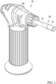
- a tool 10 with improved efficiency of an embodiment according to the present invention comprises a barrel 20, a guiding wire 30, and an electrically conductive member 40.
- the barrel 20 is made of electrically conductive material.
- the guiding wire 30 is disposed in the barrel 20.
- the barrel 20 and the guiding wire 30 are directly or indirectly connected to two opposite electrodes of a power source 50.
- the electrically conductive member 40 is connected to an outer periphery of the guiding wire 30 and is electrically connected to the guiding wire 30.
- the electrically conductive member 40 is disposed between the barrel 20 and the guiding wire 30 and is spaced from the barrel 20. When the power source 50 is activated, an electric arc is generated between the electrically conductive member 40 and the barrel 20.
- the electrically conductive member 40 is made of electrically conductive material, such as copper, aluminum, graphite, etc.
- the electrically conductive member 40 is made of electrically conductive rubber.
- the electrically conductive member 40 is annular and surrounds the guiding wire 30.
- a first edge of the electrically conductive member 40 adjacent to the guiding wire 30 is provided with an inner periphery 41 in contact with the guiding wire 30.
- the inner periphery 41 has a circular cross-sectional shape in a radial direction of the guiding wire 30.
- a second edge of the electrically conductive member 40 opposite to the guiding wire 30 is provided with an outer periphery 42 with a circular cross-sectional shape in a radial direction of the guiding wire 30.
- the outer periphery 42 may have a circular or non-circular cross-sectional shapes, the embodiment shows that the outer periphery 42 has an essentially circular cross-sectional shape.
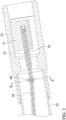
- the guiding wire 30 includes a first end 31 and a second end 32 opposite to the first end 31.
- a first insulating layer 33 and a second insulating layer 34 are disposed around the outer periphery of the guiding wire 30.
- the electrically conductive member 40 is disposed between the first insulating layer 33 and the second insulating layer 34.
- the first insulating layer 33 is disposed between the electrically conductive member 40 and the first end 31 of the guiding wire 30.
- the second insulating layer 34 is disposed between the electrically conductive member 40 and the second end 32 of the guiding wire 30.
- a fixing seat 21 is disposed in the barrel 20.
- a sheath 35 is disposed on the first end 31 of the guiding wire 30.
- the sheath 35 is disposed around the first insulating layer 33 and is connected to the fixing seat 21.
- the barrel 20 includes a front barrel 22 and a rear barrel 23.
- the fixing seat 21 is disposed on an inner periphery of the front barrel 22.
- the rear barrel 23 is connected to the front barrel 22 and is made of electrically conductive material.
- the electrically conductive member 40 is contiguous to an end of the rear barrel 23 adjacent to the front barrel 22.
- the gas tool 10 includes a body 60 in which the power source 50 is received. An end of the rear barrel 23 opposite to the front barrel 22 is received in the body 60.
- the rear barrel 23 includes a side hole 231 extending in a radial direction of the rear barrel 23 and is located in the body 60.
- the guiding wire 30 extends through the side hole 231. The second end 32 of the guiding wire 30 is located outside of the barrel 20 and is located in the body 60.
- the power source 50 is a piezoelectric igniter.
- the guiding wire 30 is flexible and is shapeable.
- the tool 10 can improve the ignition efficiency to stably accomplish the ignition.
- the tool 10 is a gas tool. Gas can flow through the barrel 20 and can be ignited by the electric arc between the electrically conductive member 40 and the barrel 20. Flame can be ejected from an end of the barrel 20 opposite to the body 60.
- the electrically conductive member 40 is connected to the outer periphery of the guiding wire 30, the spacing between the electrically conductive material of the guiding wire 30 and the electrically conductive portion of the barrel 20 can be reduced. This reduces the puncture voltage required for the puncturing phenomenon between the barrel 20 and the electrically conductive member 40, thereby increasing the success possibility of generation of electric arc between the barrel 20 and the electrically conductive member 40.
- the power source 50 is activated, the electric arc is generated between the barrel 20 and the electrically conductive member 40.
- the electric charges emitted by the power source 50 circulate along a loop formed by the barrel 20, the guiding wire 30, and the electrically conductive member 40. Thus, the service life of the power source 50 is prolonged, and the number of times of electric fire provided by the power source 50 is increased.
- a metal wire has certain flexibility and can maintain a fixed shape by tensioning.
- the location of the electrically conductive member 40 in the barrel 20 is so arranged that the guiding wire 30 in this embodiment can change its shape without being tensioned and that no matter how the guiding wire 30 changes its shape, the electrically conductive member 40 is more adjacent to the inner periphery of the barrel 20.
- the outer periphery of the electrically conductive member 40 is arcuate to present a small area most adjacent to the barrel 20. This further reduces the puncture voltage. As long as the guiding wire 30 has a proper length, the electrically conducive member 40 is always spaced from the barrel 20.
- the first insulating layer 33 and the second insulating layer 34 can be formed by peeling a rubber sheath of the guiding wire 30 to form two sections.
- the electrically conductive member 40 made of electrically conductive rubber is resilient and can be stretched across the first insulating layer 33 or the second insulating layer 34. Finally, the electrically conductive member 40 is disposed between the first insulating layer 33 and the second insulating layer 34.
- FIG. 6 shows a tool with improved efficiency of a second embodiment according to the present invention.
- the structure of the tool of this embodiment is substantially the same as that of the first embodiment except the following differences.
- a first edge of the electrically conductive member 40a adjacent to the guiding wire 30a is provided with an inner periphery 41a in contact with the guiding wire 30a
- a second edge of the electrically conductive member 40a opposite to the guiding wire 30a is provided with an outer periphery 42a with an oval cross-sectional shape in a radial direction of the guiding wire 30a.
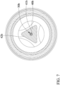
- FIG. 7 shows a tool with improved efficiency of a third embodiment according to the present invention.
- the structure of the tool of this embodiment is substantially the same as that of the first embodiment except the following differences.
- a first edge of the electrically conductive member 40b adjacent to the guiding wire 30b is provided with an inner periphery 41b in contact with the guiding wire 30b
- a second edge of the electrically conductive member 40b opposite to the guiding wire 30b is provided with an outer periphery 42b with a triangular cross-sectional shape in a radial direction of the guiding wire 30b.
- FIG. 8 shows a tool with improved efficiency of a fourth embodiment according to the present invention.
- the structure of the tool of this embodiment is substantially the same as that of the first embodiment except the following differences.
- a first edge of the electrically conductive member 40c adjacent to the guiding wire 30c is provided with an inner periphery 41c in contact with the guiding wire 30c
- a second edge of the electrically conductive member 40c opposite to the guiding wire 30c is provided with an outer periphery 42c with a quadrangular cross-sectional shape in a radial direction of the guiding wire 30c.
- FIG. 9 shows a tool with improved efficiency of a fifth embodiment according to the present invention.
- the structure of the tool of this embodiment is substantially the same as that of the first embodiment except the following differences. Specifically, a first edge of the electrically conductive member 40d adjacent to the guiding wire 30d is provided with an inner periphery 41d in contact with the guiding wire 30d, and a second edge of the electrically conductive member 40d opposite to the guiding wire 30d is provided with an outer periphery 42d with a hexagonal cross-sectional shape in a radial direction of the guiding wire 30d.
Landscapes
- Engineering & Computer Science (AREA)
- Chemical & Material Sciences (AREA)
- Combustion & Propulsion (AREA)
- Mechanical Engineering (AREA)
- General Engineering & Computer Science (AREA)
- Removal Of Insulation Or Armoring From Wires Or Cables (AREA)
- Air Bags (AREA)
Claims (13)
- Gaswerkzeug (10), mit:einem aus einem elektrisch leitendem Material hergestellten Zylinder (20);einem im Zylinder (20) angeordneten Führungsdraht (30; 30a; 30b; 30c; 30d), wobei der Zylinder (20) und der Führungsdraht (30; 30a; 30b; 30c; 30d) direkt oder indirekt mit zwei gegenüberliegenden Elektroden einer Stromquelle (50) verbunden sind; undeinem elektrisch leitenden Element (40; 40a; 40b; 40c; 40d), das mit einem Außenumfang des Führungsdrahts (30; 30a; 30b; 30c; 30d) verbunden und elektrisch mit dem Führungsdraht (30; 30a; 30b; 30c; 30d) verbunden ist,wobei das elektrisch leitende Element (40; 40a; 40b; 40c; 40d) zwischen dem Zylinder (20) und dem Führungsdraht (30; 30a; 30b; 30c; 30d) angeordnet und vom Zylinder (20) beabstandet ist,wenn die Stromquelle (50) aktiviert ist, ein elektrischer Lichtbogen zwischen dem elektrisch leitenden Element (40; 40a; 40b; 40c; 40d) und dem Zylinder (20) erzeugt wird;dadurch gekennzeichnet, dassdas elektrisch leitende Element (40; 40a; 40b; 40c; 40d) ringförmig ist und den Führungsdraht (30) umgibt.
- Gaswerkzeug nach Anspruch 1, wobei das elektrisch leitende Element (40; 40a; 40b; 40c; 40d) aus elektrisch leitendem Gummi hergestellt ist.
- Gaswerkzeug nach Anspruch 1, wobei ein erster Rand des elektrisch leitenden Elements (40), der dem Führungsdraht (30) benachbart ist, einen Innenumfang (41) aufweist, der mit dem Führungsdraht (30) in Kontakt steht, und wobei ein zweiter Rand des elektrisch leitenden Elements (40), der dem Führungsdraht (30) gegenüberliegt, einen Außenumfang (42) mit einer kreisförmigen Querschnittsform in einer radialen Richtung des Führungsdrahts (30) aufweist.
- Gaswerkzeug nach Anspruch 1, wobei ein erster Rand des elektrisch leitenden Elements (40a), der dem Führungsdraht (30a) benachbart ist, einen Innenumfang (41a) aufweist, der mit dem Führungsdraht (30a) in Kontakt steht, und wobei ein zweiter Rand des elektrisch leitenden Elements (40a), der dem Führungsdraht (30a) gegenüberliegt, einen Außenumfang (42a) mit einer ovalen Querschnittsform in einer radialen Richtung des Führungsdrahts (30a) aufweist.
- Gaswerkzeug nach Anspruch 1, wobei ein erster Rand des elektrisch leitenden Elements (40b), der dem Führungsdraht (30b) benachbart ist, einen Innenumfang (41b) aufweist, der mit dem Führungsdraht (30b) in Kontakt steht, und wobei ein zweiter Rand des elektrisch leitenden Elements (40b), der dem Führungsdraht (30b) gegenüberliegt, einen Außenumfang (42b) mit einer dreieckigen Querschnittsform in einer radialen Richtung des Führungsdrahts (30b) aufweist.
- Gaswerkzeug nach Anspruch 1, wobei ein erster Rand des elektrisch leitenden Elements (40c), der dem Führungsdraht (30c) benachbart ist, einen Innenumfang (41c) aufweist, der mit dem Führungsdraht (30c) in Kontakt steht, und wobei ein zweiter Rand des elektrisch leitenden Elements (40c), der dem Führungsdraht (30c) gegenüberliegt, einen Außenumfang (42c) mit einer viereckigen Querschnittsform in einer radialen Richtung des Führungsdrahts (30c) aufweist.
- Gaswerkzeug nach Anspruch 1, wobei ein erster Rand des elektrisch leitenden Elements (40d), der dem Führungsdraht (30d) benachbart ist, einen Innenumfang (41d) aufweist, der mit dem Führungsdraht (30d) in Kontakt steht, und wobei ein zweiter Rand des elektrisch leitenden Elements (40d), der dem Führungsdraht (30d) gegenüberliegt, einen Außenumfang (42d) mit einer sechseckigen Querschnittsform in einer radialen Richtung des Führungsdrahts (30d) aufweist.
- Gaswerkzeug nach Anspruch 1, wobei der Führungsdraht (30) ein erstes Ende (31) und ein dem ersten Ende (31) gegenüberliegendes zweites Ende (32) aufweist, wobei eine erste Isolierschicht (33) und eine zweite Isolierschicht (34) um den Außenumfang des Führungsdrahts (30) herum angeordnet sind, wobei das elektrisch leitende Element (40) zwischen der ersten Isolierschicht (33) und der zweiten Isolierschicht (34) angeordnet ist, wobei die erste Isolierschicht (33) zwischen dem elektrisch leitenden Element (40) und dem ersten Ende (31) des Führungsdrahts (30) angeordnet ist, und wobei die zweite Isolierschicht (34) zwischen dem elektrisch leitenden Element (40) und dem zweiten Ende (32) des Führungsdrahts (30) angeordnet ist.
- Gaswerkzeug nach dem vorhergehenden Anspruch, wobei ein Befestigungssitz (21) im Zylinder (20) angeordnet ist, wobei eine Hülse (35) am ersten Ende (31) des Führungsdrahts (30) angeordnet ist, und wobei die Hülse (35) um die erste Isolierschicht (33) herum angeordnet und mit dem Befestigungssitz (21) verbunden ist.
- Gaswerkzeug nach dem vorhergehenden Anspruch, wobei der Zylinder (20) einen vorderen Zylinder (22) und einen hinteren Zylinder (23) aufweist, wobei der Befestigungssitz (21) an einem Innenumfang des vorderen Zylinders (22) angeordnet ist, wobei der hintere Zylinder (23) mit dem vorderen Zylinder (22) verbunden ist und aus einem elektrisch leitendem Material besteht, und wobei das elektrisch leitende Element (40) an ein Ende des hinteren Zylinders (23), das dem vorderen Zylinder (22) benachbart ist, angrenzt.
- Gaswerkzeug nach dem vorhergehenden Anspruch, wobei das Werkzeug (10) einen Körper (60) aufweist, wobei die Stromquelle (50) im Körper (60) aufgenommen ist, wobei ein Ende des hinteren Zylinders (23), das dem vorderen Zylinder (22) gegenüberliegt, im Körper (60) aufgenommen ist, wobei der hintere Zylinder (23) ein Seitenloch (231) aufweist, das sich in einer radialen Richtung des hinteren Zylinders (23) erstreckt und im Körper (60) angeordnet ist, wobei sich der Führungsdraht (30) durch das Seitenloch (231) erstreckt, und wobei das zweite Ende (32) des Führungsdrahts (30) außerhalb des Zylinders (20) und im Körper (60) angeordnet ist.
- Gaswerkzeug nach dem vorhergehenden Anspruch, wobei die Stromquelle (50) ein piezoelektrischer Zünder ist.
- Gaswerkzeug nach Anspruch 11, wobei der Führungsdraht (30) flexibel und formbar ist.
Applications Claiming Priority (2)
| Application Number | Priority Date | Filing Date | Title |
|---|---|---|---|
| TW110102088 | 2021-01-20 | ||
| TW110105109A TWI815085B (zh) | 2021-01-20 | 2021-02-09 | 增加點火效率的工具 |
Publications (3)
| Publication Number | Publication Date |
|---|---|
| EP4033151A1 EP4033151A1 (de) | 2022-07-27 |
| EP4033151C0 EP4033151C0 (de) | 2023-10-11 |
| EP4033151B1 true EP4033151B1 (de) | 2023-10-11 |
Family
ID=78829384
Family Applications (1)
| Application Number | Title | Priority Date | Filing Date |
|---|---|---|---|
| EP21209698.6A Active EP4033151B1 (de) | 2021-01-20 | 2021-11-22 | Gaswerkzeug mit verbesserter zündwirkung |
Country Status (1)
| Country | Link |
|---|---|
| EP (1) | EP4033151B1 (de) |
Families Citing this family (1)
| Publication number | Priority date | Publication date | Assignee | Title |
|---|---|---|---|---|
| US11852342B2 (en) * | 2021-01-22 | 2023-12-26 | Pro-Iroda Industries, Inc. | Tool with improved ignition efficiency |
Family Cites Families (9)
| Publication number | Priority date | Publication date | Assignee | Title |
|---|---|---|---|---|
| US4954078A (en) * | 1986-03-14 | 1990-09-04 | Newell Companies, Inc. | Spark igniter system |
| US4881894A (en) * | 1988-02-16 | 1989-11-21 | Cooper Industries, Inc. | Self-igniting portable torch assembly |
| FR2764969B1 (fr) * | 1997-06-23 | 1999-08-20 | Applic Gaz Sa | Appareil de gaz du type desherbeur thermique |
| DE29907799U1 (de) * | 1999-05-03 | 1999-08-05 | Tsai, Chin-Lin, San Chung, Taipeh | Gasbrenner |
| WO2010059630A2 (en) * | 2008-11-18 | 2010-05-27 | Zagoroff Dimiter S | Ignition system for portable burner |
| CN201327056Y (zh) * | 2008-12-19 | 2009-10-14 | 徐聪安 | 点火枪 |
| TWM406154U (en) | 2011-01-06 | 2011-06-21 | jin-xiong Wu | Lighter and lighting structure thereof |
| TWI537528B (zh) * | 2015-03-05 | 2016-06-11 | Able to replace the barrel of the spray gun gun head | |
| CN209655351U (zh) * | 2019-01-09 | 2019-11-19 | 青岛新铃智能科技有限公司 | 一种新型安全电火花点火装置 |
-
2021
- 2021-11-22 EP EP21209698.6A patent/EP4033151B1/de active Active
Also Published As
| Publication number | Publication date |
|---|---|
| EP4033151C0 (de) | 2023-10-11 |
| EP4033151A1 (de) | 2022-07-27 |
Similar Documents
| Publication | Publication Date | Title |
|---|---|---|
| US11933493B2 (en) | Tool with improved ignition efficiency | |
| ES2623391T3 (es) | Combinación de una punta de contacto y una cabeza de retención para un soplete de soldadura con parte alargada de diámetro más ancho | |
| EP1764179A3 (de) | Kontaktspitze mit einem Flansch ; Isolierende Schutzhülse : Metallische Düse mit Greifmitteln ; Brenner zum Lichtbogenschweissen mit einem Draht und entprechenden Kontaktspitze, isolierender Schutzhülse und metallischer Düse | |
| US5975712A (en) | Telescopic illuminating tool | |
| EP1287937B1 (de) | Lichtbogenschweissbrenner zum Schutzgasmetallichtbogenschweissen | |
| US11852342B2 (en) | Tool with improved ignition efficiency | |
| ES2387581T3 (es) | Electrodo para un soplete de arco de plasma de arranque por contacto y soplete de arco de plasma de arranque por contacto que utiliza tales electrodos | |
| JP3169376U (ja) | 発光ダイオード式照明装置 | |
| EP4033151B1 (de) | Gaswerkzeug mit verbesserter zündwirkung | |
| US20160100456A1 (en) | Hand-held Multi-Function Heating Device | |
| RU2018108105A (ru) | Рентабельный картридж для плазменно-дуговой горелки | |
| US20150292721A1 (en) | Flexible Illumination Device and Method | |
| CN107073634A (zh) | 用于电弧焊设备的两件式喷嘴组件 | |
| ES2896895T3 (es) | Conjunto generador de llamas y método para fabricar un conjunto generador de llamas | |
| TWI267108B (en) | Discharge lamp, electrode for discharge lamp, method for producing electrode for discharge lamp, and illuminating device | |
| CN114857616B (zh) | 增加点火效率的工具 | |
| US20240369219A1 (en) | Flame torch | |
| TWI815085B (zh) | 增加點火效率的工具 | |
| JP2011224586A5 (de) | ||
| US3437880A (en) | Electric gas ignitor | |
| CN209763140U (zh) | 一种自动点火装置 | |
| CN222113803U (zh) | 一种组合式瓷嘴及氩弧焊枪 | |
| JPWO2023089973A5 (de) | ||
| KR20190043347A (ko) | 방향성을 갖는 디퓨져가 구비된 용접 토치 | |
| JP5725991B2 (ja) | ランプソケット及び照明器具 |
Legal Events
| Date | Code | Title | Description |
|---|---|---|---|
| PUAI | Public reference made under article 153(3) epc to a published international application that has entered the european phase |
Free format text: ORIGINAL CODE: 0009012 |
|
| STAA | Information on the status of an ep patent application or granted ep patent |
Free format text: STATUS: THE APPLICATION HAS BEEN PUBLISHED |
|
| AK | Designated contracting states |
Kind code of ref document: A1 Designated state(s): AL AT BE BG CH CY CZ DE DK EE ES FI FR GB GR HR HU IE IS IT LI LT LU LV MC MK MT NL NO PL PT RO RS SE SI SK SM TR |
|
| STAA | Information on the status of an ep patent application or granted ep patent |
Free format text: STATUS: REQUEST FOR EXAMINATION WAS MADE |
|
| 17P | Request for examination filed |
Effective date: 20230116 |
|
| RBV | Designated contracting states (corrected) |
Designated state(s): AL AT BE BG CH CY CZ DE DK EE ES FI FR GB GR HR HU IE IS IT LI LT LU LV MC MK MT NL NO PL PT RO RS SE SI SK SM TR |
|
| GRAP | Despatch of communication of intention to grant a patent |
Free format text: ORIGINAL CODE: EPIDOSNIGR1 |
|
| STAA | Information on the status of an ep patent application or granted ep patent |
Free format text: STATUS: GRANT OF PATENT IS INTENDED |
|
| INTG | Intention to grant announced |
Effective date: 20230619 |
|
| GRAS | Grant fee paid |
Free format text: ORIGINAL CODE: EPIDOSNIGR3 |
|
| GRAA | (expected) grant |
Free format text: ORIGINAL CODE: 0009210 |
|
| STAA | Information on the status of an ep patent application or granted ep patent |
Free format text: STATUS: THE PATENT HAS BEEN GRANTED |
|
| AK | Designated contracting states |
Kind code of ref document: B1 Designated state(s): AL AT BE BG CH CY CZ DE DK EE ES FI FR GB GR HR HU IE IS IT LI LT LU LV MC MK MT NL NO PL PT RO RS SE SI SK SM TR |
|
| REG | Reference to a national code |
Ref country code: GB Ref legal event code: FG4D |
|
| REG | Reference to a national code |
Ref country code: CH Ref legal event code: EP |
|
| REG | Reference to a national code |
Ref country code: DE Ref legal event code: R096 Ref document number: 602021005797 Country of ref document: DE |
|
| REG | Reference to a national code |
Ref country code: IE Ref legal event code: FG4D |
|
| U01 | Request for unitary effect filed |
Effective date: 20231103 |
|
| U07 | Unitary effect registered |
Designated state(s): AT BE BG DE DK EE FI FR IT LT LU LV MT NL PT SE SI Effective date: 20231108 |
|
| U20 | Renewal fee for the european patent with unitary effect paid |
Year of fee payment: 3 Effective date: 20231120 |
|
| PG25 | Lapsed in a contracting state [announced via postgrant information from national office to epo] |
Ref country code: GR Free format text: LAPSE BECAUSE OF FAILURE TO SUBMIT A TRANSLATION OF THE DESCRIPTION OR TO PAY THE FEE WITHIN THE PRESCRIBED TIME-LIMIT Effective date: 20240112 |
|
| PG25 | Lapsed in a contracting state [announced via postgrant information from national office to epo] |
Ref country code: IS Free format text: LAPSE BECAUSE OF FAILURE TO SUBMIT A TRANSLATION OF THE DESCRIPTION OR TO PAY THE FEE WITHIN THE PRESCRIBED TIME-LIMIT Effective date: 20240211 |
|
| PG25 | Lapsed in a contracting state [announced via postgrant information from national office to epo] |
Ref country code: ES Free format text: LAPSE BECAUSE OF FAILURE TO SUBMIT A TRANSLATION OF THE DESCRIPTION OR TO PAY THE FEE WITHIN THE PRESCRIBED TIME-LIMIT Effective date: 20231011 |
|
| PG25 | Lapsed in a contracting state [announced via postgrant information from national office to epo] |
Ref country code: IS Free format text: LAPSE BECAUSE OF FAILURE TO SUBMIT A TRANSLATION OF THE DESCRIPTION OR TO PAY THE FEE WITHIN THE PRESCRIBED TIME-LIMIT Effective date: 20240211 Ref country code: GR Free format text: LAPSE BECAUSE OF FAILURE TO SUBMIT A TRANSLATION OF THE DESCRIPTION OR TO PAY THE FEE WITHIN THE PRESCRIBED TIME-LIMIT Effective date: 20240112 Ref country code: ES Free format text: LAPSE BECAUSE OF FAILURE TO SUBMIT A TRANSLATION OF THE DESCRIPTION OR TO PAY THE FEE WITHIN THE PRESCRIBED TIME-LIMIT Effective date: 20231011 |
|
| PG25 | Lapsed in a contracting state [announced via postgrant information from national office to epo] |
Ref country code: RS Free format text: LAPSE BECAUSE OF FAILURE TO SUBMIT A TRANSLATION OF THE DESCRIPTION OR TO PAY THE FEE WITHIN THE PRESCRIBED TIME-LIMIT Effective date: 20231011 Ref country code: PL Free format text: LAPSE BECAUSE OF FAILURE TO SUBMIT A TRANSLATION OF THE DESCRIPTION OR TO PAY THE FEE WITHIN THE PRESCRIBED TIME-LIMIT Effective date: 20231011 Ref country code: NO Free format text: LAPSE BECAUSE OF FAILURE TO SUBMIT A TRANSLATION OF THE DESCRIPTION OR TO PAY THE FEE WITHIN THE PRESCRIBED TIME-LIMIT Effective date: 20240111 Ref country code: HR Free format text: LAPSE BECAUSE OF FAILURE TO SUBMIT A TRANSLATION OF THE DESCRIPTION OR TO PAY THE FEE WITHIN THE PRESCRIBED TIME-LIMIT Effective date: 20231011 |
|
| REG | Reference to a national code |
Ref country code: DE Ref legal event code: R097 Ref document number: 602021005797 Country of ref document: DE |
|
| PG25 | Lapsed in a contracting state [announced via postgrant information from national office to epo] |
Ref country code: CZ Free format text: LAPSE BECAUSE OF FAILURE TO SUBMIT A TRANSLATION OF THE DESCRIPTION OR TO PAY THE FEE WITHIN THE PRESCRIBED TIME-LIMIT Effective date: 20231011 |
|
| PG25 | Lapsed in a contracting state [announced via postgrant information from national office to epo] |
Ref country code: SK Free format text: LAPSE BECAUSE OF FAILURE TO SUBMIT A TRANSLATION OF THE DESCRIPTION OR TO PAY THE FEE WITHIN THE PRESCRIBED TIME-LIMIT Effective date: 20231011 |
|
| PG25 | Lapsed in a contracting state [announced via postgrant information from national office to epo] |
Ref country code: SM Free format text: LAPSE BECAUSE OF FAILURE TO SUBMIT A TRANSLATION OF THE DESCRIPTION OR TO PAY THE FEE WITHIN THE PRESCRIBED TIME-LIMIT Effective date: 20231011 Ref country code: SK Free format text: LAPSE BECAUSE OF FAILURE TO SUBMIT A TRANSLATION OF THE DESCRIPTION OR TO PAY THE FEE WITHIN THE PRESCRIBED TIME-LIMIT Effective date: 20231011 Ref country code: RO Free format text: LAPSE BECAUSE OF FAILURE TO SUBMIT A TRANSLATION OF THE DESCRIPTION OR TO PAY THE FEE WITHIN THE PRESCRIBED TIME-LIMIT Effective date: 20231011 Ref country code: CZ Free format text: LAPSE BECAUSE OF FAILURE TO SUBMIT A TRANSLATION OF THE DESCRIPTION OR TO PAY THE FEE WITHIN THE PRESCRIBED TIME-LIMIT Effective date: 20231011 |
|
| PLBE | No opposition filed within time limit |
Free format text: ORIGINAL CODE: 0009261 |
|
| STAA | Information on the status of an ep patent application or granted ep patent |
Free format text: STATUS: NO OPPOSITION FILED WITHIN TIME LIMIT |
|
| PG25 | Lapsed in a contracting state [announced via postgrant information from national office to epo] |
Ref country code: MC Free format text: LAPSE BECAUSE OF FAILURE TO SUBMIT A TRANSLATION OF THE DESCRIPTION OR TO PAY THE FEE WITHIN THE PRESCRIBED TIME-LIMIT Effective date: 20231011 |
|
| PG25 | Lapsed in a contracting state [announced via postgrant information from national office to epo] |
Ref country code: MC Free format text: LAPSE BECAUSE OF FAILURE TO SUBMIT A TRANSLATION OF THE DESCRIPTION OR TO PAY THE FEE WITHIN THE PRESCRIBED TIME-LIMIT Effective date: 20231011 |
|
| REG | Reference to a national code |
Ref country code: IE Ref legal event code: MM4A |
|
| 26N | No opposition filed |
Effective date: 20240712 |
|
| PG25 | Lapsed in a contracting state [announced via postgrant information from national office to epo] |
Ref country code: IE Free format text: LAPSE BECAUSE OF NON-PAYMENT OF DUE FEES Effective date: 20231122 |
|
| PG25 | Lapsed in a contracting state [announced via postgrant information from national office to epo] |
Ref country code: IE Free format text: LAPSE BECAUSE OF NON-PAYMENT OF DUE FEES Effective date: 20231122 |
|
| U20 | Renewal fee for the european patent with unitary effect paid |
Year of fee payment: 4 Effective date: 20241126 |
|
| REG | Reference to a national code |
Ref country code: CH Ref legal event code: PL |
|
| REG | Reference to a national code |
Ref country code: CH Ref legal event code: PL |
|
| PG25 | Lapsed in a contracting state [announced via postgrant information from national office to epo] |
Ref country code: CH Free format text: LAPSE BECAUSE OF NON-PAYMENT OF DUE FEES Effective date: 20241130 |
|
| PG25 | Lapsed in a contracting state [announced via postgrant information from national office to epo] |
Ref country code: CY Free format text: LAPSE BECAUSE OF FAILURE TO SUBMIT A TRANSLATION OF THE DESCRIPTION OR TO PAY THE FEE WITHIN THE PRESCRIBED TIME-LIMIT; INVALID AB INITIO Effective date: 20211122 |
|
| PG25 | Lapsed in a contracting state [announced via postgrant information from national office to epo] |
Ref country code: TR Free format text: LAPSE BECAUSE OF FAILURE TO SUBMIT A TRANSLATION OF THE DESCRIPTION OR TO PAY THE FEE WITHIN THE PRESCRIBED TIME-LIMIT Effective date: 20231011 |
|
| U20 | Renewal fee for the european patent with unitary effect paid |
Year of fee payment: 5 Effective date: 20251126 |