EP4033048A1 - Method of manufacture of the facade thermal insulation finishing element and the finishing element obtained therethrough - Google Patents
Method of manufacture of the facade thermal insulation finishing element and the finishing element obtained therethrough Download PDFInfo
- Publication number
- EP4033048A1 EP4033048A1 EP21156749.0A EP21156749A EP4033048A1 EP 4033048 A1 EP4033048 A1 EP 4033048A1 EP 21156749 A EP21156749 A EP 21156749A EP 4033048 A1 EP4033048 A1 EP 4033048A1
- Authority
- EP
- European Patent Office
- Prior art keywords
- thermal insulation
- insulation board
- mixture
- perforated
- perforated fastening
- Prior art date
- Legal status (The legal status is an assumption and is not a legal conclusion. Google has not performed a legal analysis and makes no representation as to the accuracy of the status listed.)
- Granted
Links
Images



Classifications
-
- E—FIXED CONSTRUCTIONS
- E04—BUILDING
- E04F—FINISHING WORK ON BUILDINGS, e.g. STAIRS, FLOORS
- E04F13/00—Coverings or linings, e.g. for walls or ceilings
- E04F13/07—Coverings or linings, e.g. for walls or ceilings composed of covering or lining elements; Sub-structures therefor; Fastening means therefor
- E04F13/08—Coverings or linings, e.g. for walls or ceilings composed of covering or lining elements; Sub-structures therefor; Fastening means therefor composed of a plurality of similar covering or lining elements
- E04F13/0801—Separate fastening elements
- E04F13/0832—Separate fastening elements without load-supporting elongated furring elements between wall and covering elements
- E04F13/0833—Separate fastening elements without load-supporting elongated furring elements between wall and covering elements not adjustable
- E04F13/0835—Separate fastening elements without load-supporting elongated furring elements between wall and covering elements not adjustable the fastening elements extending into the back side of the covering elements
- E04F13/0837—Separate fastening elements without load-supporting elongated furring elements between wall and covering elements not adjustable the fastening elements extending into the back side of the covering elements extending completely through the covering elements
-
- E—FIXED CONSTRUCTIONS
- E04—BUILDING
- E04F—FINISHING WORK ON BUILDINGS, e.g. STAIRS, FLOORS
- E04F13/00—Coverings or linings, e.g. for walls or ceilings
- E04F13/07—Coverings or linings, e.g. for walls or ceilings composed of covering or lining elements; Sub-structures therefor; Fastening means therefor
- E04F13/08—Coverings or linings, e.g. for walls or ceilings composed of covering or lining elements; Sub-structures therefor; Fastening means therefor composed of a plurality of similar covering or lining elements
- E04F13/0875—Coverings or linings, e.g. for walls or ceilings composed of covering or lining elements; Sub-structures therefor; Fastening means therefor composed of a plurality of similar covering or lining elements having a basic insulating layer and at least one covering layer
-
- E—FIXED CONSTRUCTIONS
- E04—BUILDING
- E04F—FINISHING WORK ON BUILDINGS, e.g. STAIRS, FLOORS
- E04F13/00—Coverings or linings, e.g. for walls or ceilings
- E04F13/07—Coverings or linings, e.g. for walls or ceilings composed of covering or lining elements; Sub-structures therefor; Fastening means therefor
- E04F13/08—Coverings or linings, e.g. for walls or ceilings composed of covering or lining elements; Sub-structures therefor; Fastening means therefor composed of a plurality of similar covering or lining elements
- E04F13/0801—Separate fastening elements
- E04F13/0832—Separate fastening elements without load-supporting elongated furring elements between wall and covering elements
- E04F13/0833—Separate fastening elements without load-supporting elongated furring elements between wall and covering elements not adjustable
- E04F13/0851—Hooking means on the back side of the covering elements
-
- E—FIXED CONSTRUCTIONS
- E04—BUILDING
- E04F—FINISHING WORK ON BUILDINGS, e.g. STAIRS, FLOORS
- E04F13/00—Coverings or linings, e.g. for walls or ceilings
- E04F13/07—Coverings or linings, e.g. for walls or ceilings composed of covering or lining elements; Sub-structures therefor; Fastening means therefor
- E04F13/08—Coverings or linings, e.g. for walls or ceilings composed of covering or lining elements; Sub-structures therefor; Fastening means therefor composed of a plurality of similar covering or lining elements
- E04F13/14—Coverings or linings, e.g. for walls or ceilings composed of covering or lining elements; Sub-structures therefor; Fastening means therefor composed of a plurality of similar covering or lining elements stone or stone-like materials, e.g. ceramics concrete; of glass or with an outer layer of stone or stone-like materials or glass
- E04F13/141—Coverings or linings, e.g. for walls or ceilings composed of covering or lining elements; Sub-structures therefor; Fastening means therefor composed of a plurality of similar covering or lining elements stone or stone-like materials, e.g. ceramics concrete; of glass or with an outer layer of stone or stone-like materials or glass with an outer layer of concrete
Definitions
- the invention relates to the construction industry, and more particularly to a method of manufacturing a thermal insulation finishing element for insulating and decorating the external walls of buildings and to a thermal insulating finishing element obtained thereby.
- the external walls of buildings are insulated by covering them with a suitable thermal insulation material, such as polystyrene foam panels or thermal insulation wool, which are then covered with a desired finish such as plaster, clinker tiles, granite, marble, aluminum or others.
- a suitable thermal insulation material such as polystyrene foam panels or thermal insulation wool
- the thermal insulation material is attached to the external surface of the building with glue or pins or in combination of both methods.
- European patent No. EP2675962 describes the construction, production and installation methods of a thermal insulation product for the insulation and finishing of the external walls of buildings.
- the product of the invention consists essentially of two elements: a thermal insulation material and a finishing board.
- the finishing board can be made of ceramic, plastic, wood, glass, metal, aluminum, granite, natural stone, marble, laminate and other materials suitable for finishing.
- the thermal insulation material is a polyurethane or extruded polyester board, the outer side of which is covered with a finishing board, glued to the thermal insulation board with a polyurethane adhesive covering the entire inner surface of the finishing board.
- the final product thus obtained - a thermal insulation board with an external finish - is attached to the outer wall of the building with either glue or pins.
- the invention describes a thermal insulation finishing element for fixing to the outer wall of a building, where the finishing layer is formed directly on the outer surface of the thermal insulation board.
- the method according to this invention is realized by creating a cement mixture with special properties, which, using a special technology, is inseparably connected to the thermal insulation board.
- a thermal insulation finishing element is obtained, which has an integrated 8-15 mm thick decorative finishing layer with a surface imitating marble, natural stone or other decorative finishing.
- the thermal insulation finishing element is attached to the external wall of the building both mechanically with pins through appropriate perforated metal strips attached to the inside of the thermal insulation finishing board and with the usual adhesives for attaching polystyrene foam to the external wall of the building.
- the object of the present invention is to improve the previous method of manufacturing a thermal insulation finishing element, which would include a technology for the production of a thermal insulation finishing element with integrated elements for its fastening to a building facade.
- a plurality of perforated metal strips are first inserted into the thermal insulation board, which is preferably a polystyrene foam board, for fixing the final formed thermal insulation finishing element to the building facade.
- the perforated fastening strips are inserted across the thermal insulation board and are directed diagonally downwards from the upper edge of the inner side of the thermal insulation board over the entire thickness of the thermal insulation board.
- Several such perforated fastening strips are inserted over the entire length of the thermal insulation board and their number depends on the length of the thermal insulation board.
- Perforated fastening strips for fastening the thermal insulation finishing element to the wall of the building facade are inserted so that their inner and outer ends remain partially protruding on opposite inner and outer sides.
- the protruding ends of the perforated strips are folded so that the inner end of the perforated fastening strip faces vertically upwards and the outer end of the perforated strip faces vertically downwards, covering a part of the outer surface of the thermal insulation board.
- the thermal insulation board is now ready to be covered with an outer finishing layer.
- a special cement mixture consisting of cement, sand, basalt fiber, various pigments, a hydrophobic additive, an air removal additive, a plasticizer, is added to the mixer.
- the mixer is switched on, and water and plasticizers are added to the mixture.
- the resulting mass is poured into special paraffin-coated PVC moulds corresponding to the shape of the thermal insulation element and having the desired relief of the outer surface of the thermal insulation element.
- the mould with the mixture is placed on a vibrating table and vibrated.
- a thermal insulation element with already inserted perforated fastening strips is placed in the mould on the vibrated mass, and the lower surface of the board, which is at the same time the outer (facade) surface of the thermal insulation finishing element, is connected with the mixture by means of a pressure.
- the product is dried in the mould, then removed from the mould and finally dried.
- thermal insulation finishing element one surface of which is inextricably joined with the cementitious mixture forming the outer decorative finishing layer without the use of any additional intermediate polyurethane adhesive, and the opposite surface has protruding ends of perforated fastening strips designed for fastening the thermal insulation finishing element to the facade of the building.
- Selecting the appropriate pigments results in decorative finishing layers of the thermal insulation element in different colours and patterns, imitating, for example, marble, natural stone or other decorative finishes.
- the cementitious mixture of the present invention pressurized with a thermal insulation element, acquires the properties of a monolith in the final product, becoming resistant to mechanical and atmospheric-temperature effects, while giving the exterior of an insulated building an aesthetic decorative appearance.
- the thermal insulation finishing element obtained by the method of the present invention is fastened to the outer wall of the building mechanically by means of pins through corresponding openings in the inner ends of the perforated metal fastening strips pierced transversely through the thermal insulation element.
- the outer ends of the perforated fastening strips under the finishing layer are folded vertically downwards, partially embracing the thermal insulation element and ensuring its reliable pressure on and non-separation from the building facade.
- the object of the invention is to produce a thermal insulation finishing element with integrated elements of its fastening to the external wall of a building.
- thermal insulation finishing element refers to a thermal insulating board, usually in the shape of a rectangular parallelepiped, having integrated elements for its attachment to the wall of the building, and a decorative layer on the outer surface facing the viewer.
- the thermal insulation finishing element 1 comprises a thermal insulation board 2, preferably a polystyrene foam board, having the integrated perforated metal strips 3 for attaching the thermal insulation finishing element 1 to the exterior wall of the building, and a decorative finishing layer 1 covering the surface of the thermal insulation board 2 facing the viewer.
- the perforated fastening strips 3 are pierced across the thermal insulation board 2 and are directed diagonally downwards from the upper edge of the inner side of the thermal insulation board 2 over the entire thickness of the thermal insulation board 2 towards the outer side of the thermal insulation board 2.
- Several such perforated metal strips 3 are inserted over the entire length of the thermal insulation board 2 and their number depends on the length of the thermal insulation board 2.
- the distance a between adjacent perforated fastening strips 3 would be between 30-40 cm, and the distance b from the lateral perforated fastening strips 3 to the side edge of the thermal insulation board 2 would not exceed 20 cm.
- the perforated metal strips 3 are pierced across the thermal insulation board 2. They are directed at an angle of approximately 45° from the upper edge of the inner side of the thermal insulation board 2 down the entire thickness of the thermal insulation board 2.
- the perforated fastening strips 3 are intended for fixing the thermal insulation finishing element 1 to the wall of the building facade and are inserted rated so that their inner ends 3a and outer 3b remain protruding on opposite inner and outer sides of the thermal insulation board 2.
- the length of the end 3a of the perforated fastening strip 3 is about 50 mm and the length of the end 3b is about 80 mm.
- the protruding ends 3a and 3b of the perforated fastening strips 3 are folded so that the inner end of the perforated fastening strip 3a for fastening to the building wall is directed vertically upwards and the outer end 3b of the perforated fastening strip is directed vertically downwards and pressed against the outer surface of the thermal insulation board 2.
- the part 3c of the perforated fastening strip 3b is bent at a right angle to the inside of the thermal insulation board 2, thus engaging with the thermal insulation board 2. This method of mounting the perforated fastening strips 3 ensures reliable fixation of the thermal insulation finishing element 1 and its pressing against the external wall of the building.
- the thermal insulation board 2 is forwarded to the next stage, i.e. for forming a decorative finishing layer 4 on the outer surface of the thermal insulation board 2.
- a special mixture has been created to form the decorative finishing layer 4, the components of which consist of:
- the finishing layer is formed on the thermal insulation board 2 in the following way: the components of the cementitious mixture are added to the mixer in the proportions given above. When the mixer is switched on, water is added in amount from 8 to 9% w/w of the cementitious mixture. The mixture is stirred up for 10 to 15 minutes until a homogeneous mass of the mixture is obtained. The resulting mixture is poured into PVC moulds, coated beforehand with a paraffin mixture. The PVC mould with the mixture is placed on a vibrating table and vibrated for 30 to 90 seconds, preferably up to 60 seconds.
- a pressure of 0.4-1.0 MPa the thermal insulation board 2 is joined with the cementitious mixture and left to dry at a temperature of 20-22°C and a humidity of 70-90% for up to 24 hours.
- the product is removed from the mould and finally dried to give a thermal insulation finishing element 1, shown in Fig. 1 , with an integrated 8-15 mm thick decorative finishing layer 4 covering the outer ends 3b of the perforated fastening strips 3.
- the decorative finishing layer 4, formed on the outer surface of the thermal insulation board 2, achieves monolithic properties resistant to mechanical and atmospheric or temperature impacts, while providing an aesthetic view to the facade of the building covered with thermal insulation finishing elements 1 of the present invention.
- the thermal insulation finishing element 1 is fastened to the outer wall of the building mechanically by means of pins through the respective inner ends 3a of the perforated fastening strips 3.
- decorative finishing layers 4 of different colours and patterns are obtained, having a surface imitating marble, natural stone or other decorative finishes.
- the invention is described with reference to a method of manufacturing a rectangular parallelepiped-shaped thermal insulation finishing element having only one decorative surface. It is obvious that the method can be equally applied to the production of other forms of thermal insulation finishing elements with a decorative coating applied to more than one surface of the same thermal insulation element and intended, for example, for insulation and decoration of the external corners of buildings.
Landscapes
- Engineering & Computer Science (AREA)
- Architecture (AREA)
- Civil Engineering (AREA)
- Structural Engineering (AREA)
- Building Environments (AREA)
- Finishing Walls (AREA)
- Press-Shaping Or Shaping Using Conveyers (AREA)
Abstract
Description
- The invention relates to the construction industry, and more particularly to a method of manufacturing a thermal insulation finishing element for insulating and decorating the external walls of buildings and to a thermal insulating finishing element obtained thereby.
- Currently, in the construction industry, the external walls of buildings are insulated by covering them with a suitable thermal insulation material, such as polystyrene foam panels or thermal insulation wool, which are then covered with a desired finish such as plaster, clinker tiles, granite, marble, aluminum or others. The thermal insulation material is attached to the external surface of the building with glue or pins or in combination of both methods.
- Such a method of thermal insulation and finishing of the external walls of buildings becomes problematic to implement in the presence of negative air temperature, because both the finishing of the thermal insulation material and its gluing to the external wall of the building can be performed only at a positive outdoor temperature.
- European patent No.
EP2675962 describes the construction, production and installation methods of a thermal insulation product for the insulation and finishing of the external walls of buildings. The product of the invention consists essentially of two elements: a thermal insulation material and a finishing board. The finishing board can be made of ceramic, plastic, wood, glass, metal, aluminum, granite, natural stone, marble, laminate and other materials suitable for finishing. The thermal insulation material is a polyurethane or extruded polyester board, the outer side of which is covered with a finishing board, glued to the thermal insulation board with a polyurethane adhesive covering the entire inner surface of the finishing board. The final product thus obtained - a thermal insulation board with an external finish - is attached to the outer wall of the building with either glue or pins. - Another variant of realization of a thermal insulation product for insulation of the external walls of buildings is described in Lithuanian patent No.
6693 - The object of the present invention is to improve the previous method of manufacturing a thermal insulation finishing element, which would include a technology for the production of a thermal insulation finishing element with integrated elements for its fastening to a building facade.
- According to the present invention, a plurality of perforated metal strips are first inserted into the thermal insulation board, which is preferably a polystyrene foam board, for fixing the final formed thermal insulation finishing element to the building facade. The perforated fastening strips are inserted across the thermal insulation board and are directed diagonally downwards from the upper edge of the inner side of the thermal insulation board over the entire thickness of the thermal insulation board. Several such perforated fastening strips are inserted over the entire length of the thermal insulation board and their number depends on the length of the thermal insulation board.
- Perforated fastening strips for fastening the thermal insulation finishing element to the wall of the building facade are inserted so that their inner and outer ends remain partially protruding on opposite inner and outer sides. The protruding ends of the perforated strips are folded so that the inner end of the perforated fastening strip faces vertically upwards and the outer end of the perforated strip faces vertically downwards, covering a part of the outer surface of the thermal insulation board.
- The thermal insulation board is now ready to be covered with an outer finishing layer. First, a special cement mixture, consisting of cement, sand, basalt fiber, various pigments, a hydrophobic additive, an air removal additive, a plasticizer, is added to the mixer. The mixer is switched on, and water and plasticizers are added to the mixture. The resulting mass is poured into special paraffin-coated PVC moulds corresponding to the shape of the thermal insulation element and having the desired relief of the outer surface of the thermal insulation element. The mould with the mixture is placed on a vibrating table and vibrated. A thermal insulation element with already inserted perforated fastening strips is placed in the mould on the vibrated mass, and the lower surface of the board, which is at the same time the outer (facade) surface of the thermal insulation finishing element, is connected with the mixture by means of a pressure. The product is dried in the mould, then removed from the mould and finally dried.
- In this way a ready-to-attach thermal insulation finishing element is obtained, one surface of which is inextricably joined with the cementitious mixture forming the outer decorative finishing layer without the use of any additional intermediate polyurethane adhesive, and the opposite surface has protruding ends of perforated fastening strips designed for fastening the thermal insulation finishing element to the facade of the building. Selecting the appropriate pigments results in decorative finishing layers of the thermal insulation element in different colours and patterns, imitating, for example, marble, natural stone or other decorative finishes.
- The cementitious mixture of the present invention, pressurized with a thermal insulation element, acquires the properties of a monolith in the final product, becoming resistant to mechanical and atmospheric-temperature effects, while giving the exterior of an insulated building an aesthetic decorative appearance. The thermal insulation finishing element obtained by the method of the present invention is fastened to the outer wall of the building mechanically by means of pins through corresponding openings in the inner ends of the perforated metal fastening strips pierced transversely through the thermal insulation element. As mentioned earlier, the outer ends of the perforated fastening strips under the finishing layer are folded vertically downwards, partially embracing the thermal insulation element and ensuring its reliable pressure on and non-separation from the building facade.
-
-
Fig. 1 is a general view of a thermal insulation finishing element of the present invention; -
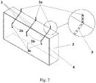
Fig. 2 shows a three-dimensional view of the thermal insulation finishing element; -
Fig. 3 is a top view of a thermal insulation finishing element; -
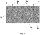
Fig. 4 is a front view of a thermal insulation finishing element; -
Fig. 5 is the cross-sectional view of the thermal insulation finishing element ofFig. 1 through the line A-A. - As mentioned, the object of the invention is to produce a thermal insulation finishing element with integrated elements of its fastening to the external wall of a building. In the present invention, the term "thermal insulation finishing element" refers to a thermal insulating board, usually in the shape of a rectangular parallelepiped, having integrated elements for its attachment to the wall of the building, and a decorative layer on the outer surface facing the viewer.
- The invention will further be described with reference to
Figures 1-5 . According to the present invention, the thermalinsulation finishing element 1 comprises athermal insulation board 2, preferably a polystyrene foam board, having the integratedperforated metal strips 3 for attaching the thermalinsulation finishing element 1 to the exterior wall of the building, and adecorative finishing layer 1 covering the surface of thethermal insulation board 2 facing the viewer. - As shown in
Fig. 2 , theperforated fastening strips 3 are pierced across thethermal insulation board 2 and are directed diagonally downwards from the upper edge of the inner side of thethermal insulation board 2 over the entire thickness of thethermal insulation board 2 towards the outer side of thethermal insulation board 2. Several suchperforated metal strips 3 are inserted over the entire length of thethermal insulation board 2 and their number depends on the length of thethermal insulation board 2. For reliable fastening of the thermalinsulation finishing element 1 to the external wall of the building, it is recommended that the distance a between adjacentperforated fastening strips 3 would be between 30-40 cm, and the distance b from the lateral perforatedfastening strips 3 to the side edge of thethermal insulation board 2 would not exceed 20 cm. - As mentioned, the
perforated metal strips 3 are pierced across thethermal insulation board 2. They are directed at an angle of approximately 45° from the upper edge of the inner side of thethermal insulation board 2 down the entire thickness of thethermal insulation board 2. - The perforated
fastening strips 3 are intended for fixing the thermalinsulation finishing element 1 to the wall of the building facade and are inserted rated so that theirinner ends 3a and outer 3b remain protruding on opposite inner and outer sides of thethermal insulation board 2. - Preferably, the length of the
end 3a of the perforatedfastening strip 3 is about 50 mm and the length of theend 3b is about 80 mm. Theprotruding ends fastening strips 3 are folded so that the inner end of the perforatedfastening strip 3a for fastening to the building wall is directed vertically upwards and theouter end 3b of the perforated fastening strip is directed vertically downwards and pressed against the outer surface of thethermal insulation board 2. In addition, thepart 3c of the perforatedfastening strip 3b is bent at a right angle to the inside of thethermal insulation board 2, thus engaging with thethermal insulation board 2. This method of mounting theperforated fastening strips 3 ensures reliable fixation of the thermalinsulation finishing element 1 and its pressing against the external wall of the building. - After installing the
perforated fastening strips 3, thethermal insulation board 2 is forwarded to the next stage, i.e. for forming adecorative finishing layer 4 on the outer surface of thethermal insulation board 2. A special mixture has been created to form thedecorative finishing layer 4, the components of which consist of: - cement and 0/2 mm fraction sand in a ratio of 1:2 to 1:3, preferably 1:2.5;
- basalt fiber up to 0.3% w/w of the cementitious mixture;
- pigment from 0.5 to 1.0% w/w of the cementitious mixture to obtain the desired colour of the finishing layer;
- hydrophobizing agent from 0.2 to 0.3% w/w of the cementitious mixture;
- air removal additive up to 0.2% w/w of the cementitious mixture;
- plasticizer up to 0.5% w/w of the cementitious mixture.
- The finishing layer is formed on the
thermal insulation board 2 in the following way: the components of the cementitious mixture are added to the mixer in the proportions given above. When the mixer is switched on, water is added in amount from 8 to 9% w/w of the cementitious mixture. The mixture is stirred up for 10 to 15 minutes until a homogeneous mass of the mixture is obtained. The resulting mixture is poured into PVC moulds, coated beforehand with a paraffin mixture. The PVC mould with the mixture is placed on a vibrating table and vibrated for 30 to 90 seconds, preferably up to 60 seconds. - During further vibration, a
thermal insulation board 2 withperforated fastening strips 3, installed into thethermal insulation board 2 in a previous step, is pressed into the liquid cementitious mixture with a side having theends 3b of the perforated fastening strips 3. By applying a pressure of 0.4-1.0 MPa, thethermal insulation board 2 is joined with the cementitious mixture and left to dry at a temperature of 20-22°C and a humidity of 70-90% for up to 24 hours. Finally, the product is removed from the mould and finally dried to give a thermalinsulation finishing element 1, shown inFig. 1 , with an integrated 8-15 mm thickdecorative finishing layer 4 covering the outer ends 3b of the perforated fastening strips 3. - The
decorative finishing layer 4, formed on the outer surface of thethermal insulation board 2, achieves monolithic properties resistant to mechanical and atmospheric or temperature impacts, while providing an aesthetic view to the facade of the building covered with thermalinsulation finishing elements 1 of the present invention. The thermalinsulation finishing element 1 is fastened to the outer wall of the building mechanically by means of pins through the respective inner ends 3a of the perforated fastening strips 3. - By selecting the appropriate pigments,
decorative finishing layers 4 of different colours and patterns are obtained, having a surface imitating marble, natural stone or other decorative finishes. - The invention is described with reference to a method of manufacturing a rectangular parallelepiped-shaped thermal insulation finishing element having only one decorative surface. It is obvious that the method can be equally applied to the production of other forms of thermal insulation finishing elements with a decorative coating applied to more than one surface of the same thermal insulation element and intended, for example, for insulation and decoration of the external corners of buildings.
Claims (8)
- A method of manufacturing a thermal insulation finishing element for insulating and decorating the exterior walls of buildings, comprising formation of a decorative finishing layer on the outer surface of the thermal insulation board, characterized in the steps of:a) installing in the thermal insulation board (2) of perforated metal strips (3) for holding the thermal insulation board (2) and fixing it to the facade of the building; andb) forming a decorative finishing layer (4) on the outer surface of the thermal insulation board (2).
- The method according to claim 1, characterized in that the perforated fastening strips (3) are inserted transversely of the thermal insulation board (2) and directed at an angle of approximately 45° downwards from the upper edge of the inner side of the thermal insulation board (2) over the entire thickness of the thermal insulation board (2) towards the outer side of the thermal insulation board 2.
- The method according to claims 1 and 2, characterized in that the perforated fastening strips (3) are installed so that their inner (3a) and outer (3b) ends remain protruding on opposite inner and outer sides of the thermal insulation board (2), and are bent so that the inner end (3a) of the perforated fastening strip (3) for fixing the thermal insulation board (2) to the facade of the building is directed vertically upwards, and the outer end (3b) of the perforated fastening strip (3) is directed vertically downwards, covering a part of the outer surface of the thermal insulation board (2).
- The method according to claim 3, characterized in that the length of the end (3a) of the perforated fastening strip (3) is optimally up to 50 mm and the length of the end (3b) of the perforated fastening strip (3) is up to 80 mm.
- The method according to claim 3, characterized in that the part (3c) of the outer end (3b) of the perforated fastening strip (3) is bent at a right angle into the interior of the thermal insulation board (2), thus engaging with the thermal insulation board (2).
- The method according to claims 1-5, characterized in that the distance a between the adjacent perforated fastening strips (3) is in the range between 30-40 cm, and the distance b from the lateral perforated fastening strips (3) to the side edge of the thermal insulation board (2) does not exceed 20 cm.
- The method according to claim 1, characterized in that the formation of the decorative finishing layer (4) on the outer surface of the thermal insulation board (2) comprises the following steps:a) preparing the mixture consisting of:- cement and 0/2 mm fraction sand in a ratio of 1:2 to 1:3, preferably 1:2.5;- basalt fiber up to 0.3% w/w of the cementitious mixture;- pigment from 0.5 to 1.0% w/w of the cementitious mixture to obtain the desired colour of the finishing layer;- hydrophobizing agent from 0.2 to 0.3% w/w of the cementitious mixture;- air removal additive up to 0.2% w/w of the cementitious mixture;- plasticizer up to 0.5% w/w of the cementitious mixture;b) with the mixer switched on, adding water in amount of 8 to 9% w/w of the cementitious mixture;c) stirring up the mixture for 10 to 15 minutes to obtain a homogeneous mass of the mixture;d) pouring the resulting mixture into PVC moulds coated beforehand with a paraffin mixture;e) placing the PVC mould with the mixture on a vibrating table and vibrating for 30 to 90 seconds, preferably up to 60 seconds;f) pressing the thermal insulation board (2) with the pre-installed perforated fastening strips (3) into the pre-vibrated liquid cementitious mass with the side having the ends (3b) of the perforated fastening strips (3);g) applying a pressure of 0.4-1.0 MPa to connect the thermal insulation board (2) with the cementitious mixture, and letting dry at a temperature of 20-22°C and a humidity of 70-90% for up to 24 hours;h) removing the product from the mould and finally drying to obtain a final thermal insulation finishing element (1) with an integrated 8-15 mm thick finishing layer (4).
- A thermal insulating finishing element (1) obtained by a method according to claims 1-7 for insulation and decoration of external walls of buildings.
Priority Applications (3)
| Application Number | Priority Date | Filing Date | Title |
|---|---|---|---|
| SM20230349T SMT202300349T1 (en) | 2021-01-22 | 2021-02-12 | Method of manufacture of the facade thermal insulation finishing element |
| HRP20231246TT HRP20231246T1 (en) | 2021-01-22 | 2021-02-12 | Method of manufacture of the facade thermal insulation finishing element |
| RS20230913A RS64669B1 (en) | 2021-01-22 | 2021-02-12 | Method of manufacture of the facade thermal insulation finishing element |
Applications Claiming Priority (1)
| Application Number | Priority Date | Filing Date | Title |
|---|---|---|---|
| LT2021503A LT6928B (en) | 2021-01-22 | 2021-01-22 | Method of production of facade thermal insulation finishing element and finishing element obtained in this way |
Publications (3)
| Publication Number | Publication Date |
|---|---|
| EP4033048A1 true EP4033048A1 (en) | 2022-07-27 |
| EP4033048B1 EP4033048B1 (en) | 2023-08-30 |
| EP4033048C0 EP4033048C0 (en) | 2023-08-30 |
Family
ID=74595097
Family Applications (1)
| Application Number | Title | Priority Date | Filing Date |
|---|---|---|---|
| EP21156749.0A Active EP4033048B1 (en) | 2021-01-22 | 2021-02-12 | Method of manufacture of the facade thermal insulation finishing element |
Country Status (8)
| Country | Link |
|---|---|
| EP (1) | EP4033048B1 (en) |
| ES (1) | ES2961552T3 (en) |
| HR (1) | HRP20231246T1 (en) |
| HU (1) | HUE063962T2 (en) |
| LT (1) | LT6928B (en) |
| PL (1) | PL4033048T3 (en) |
| RS (1) | RS64669B1 (en) |
| SM (1) | SMT202300349T1 (en) |
Citations (5)
| Publication number | Priority date | Publication date | Assignee | Title |
|---|---|---|---|---|
| EP0091858A1 (en) * | 1982-04-08 | 1983-10-19 | Societe De Construction Industrielle Du Batiment - Socib | Exterior insulating facing for building walls |
| US5715637A (en) * | 1995-04-27 | 1998-02-10 | Pan-Brick, Inc. | Prefabricated composite building panel with improved fire retardancy |
| WO2008097113A2 (en) * | 2007-02-09 | 2008-08-14 | Mr-Pur Izolacje | A facade element, especially a facade board and the method of manufacturing the facade element |
| EP2675962A1 (en) | 2011-02-15 | 2013-12-25 | Vitra Karo Sanayi Ve Ticaret Anonim Sirketi | Heat insulation for the outer sidings of the buildings |
| LT6693B (en) | 2019-06-26 | 2020-01-27 | UAB "Koderus" | Method of manufacture of the thermal insulation panel and the thermal insulation panel thus obtained |
-
2021
- 2021-01-22 LT LT2021503A patent/LT6928B/en unknown
- 2021-02-12 HR HRP20231246TT patent/HRP20231246T1/en unknown
- 2021-02-12 HU HUE21156749A patent/HUE063962T2/en unknown
- 2021-02-12 EP EP21156749.0A patent/EP4033048B1/en active Active
- 2021-02-12 ES ES21156749T patent/ES2961552T3/en active Active
- 2021-02-12 SM SM20230349T patent/SMT202300349T1/en unknown
- 2021-02-12 PL PL21156749.0T patent/PL4033048T3/en unknown
- 2021-02-12 RS RS20230913A patent/RS64669B1/en unknown
Patent Citations (5)
| Publication number | Priority date | Publication date | Assignee | Title |
|---|---|---|---|---|
| EP0091858A1 (en) * | 1982-04-08 | 1983-10-19 | Societe De Construction Industrielle Du Batiment - Socib | Exterior insulating facing for building walls |
| US5715637A (en) * | 1995-04-27 | 1998-02-10 | Pan-Brick, Inc. | Prefabricated composite building panel with improved fire retardancy |
| WO2008097113A2 (en) * | 2007-02-09 | 2008-08-14 | Mr-Pur Izolacje | A facade element, especially a facade board and the method of manufacturing the facade element |
| EP2675962A1 (en) | 2011-02-15 | 2013-12-25 | Vitra Karo Sanayi Ve Ticaret Anonim Sirketi | Heat insulation for the outer sidings of the buildings |
| LT6693B (en) | 2019-06-26 | 2020-01-27 | UAB "Koderus" | Method of manufacture of the thermal insulation panel and the thermal insulation panel thus obtained |
Also Published As
| Publication number | Publication date |
|---|---|
| HRP20231246T1 (en) | 2024-02-02 |
| PL4033048T3 (en) | 2024-01-29 |
| LT2021503A (en) | 2022-07-25 |
| EP4033048B1 (en) | 2023-08-30 |
| SMT202300349T1 (en) | 2023-11-13 |
| HUE063962T2 (en) | 2024-02-28 |
| EP4033048C0 (en) | 2023-08-30 |
| ES2961552T3 (en) | 2024-03-12 |
| LT6928B (en) | 2022-08-10 |
| RS64669B1 (en) | 2023-11-30 |
Similar Documents
| Publication | Publication Date | Title |
|---|---|---|
| CA1250727A (en) | Use of fibrous mat-faced gypsum board in exterior finishing sytems for buildings and shaft wall assemblies | |
| JPH10506086A (en) | Panels or building materials for floors, walls, ceilings, or furniture, methods for producing the panels or building materials, and holders for the panels | |
| US20060003144A1 (en) | Modular, raised panels and methods of manufacturing the same | |
| EP2789765A1 (en) | Stone panel formed unitary with insulation material for covering a wall and method for manufacturing it | |
| EP3132100B1 (en) | Flexible cladding wrap | |
| EP4033048A1 (en) | Method of manufacture of the facade thermal insulation finishing element and the finishing element obtained therethrough | |
| KR20040040227A (en) | Method for manufacture of articial stone plate for interior outside a structure | |
| CN100376755C (en) | Dry hanging external and internal wall surface decoration structure of fibrous porcelain plate back lining and it's construction method | |
| KR20140024135A (en) | Architectural board and method for manufacturing and construction process of the same | |
| KR20090010130A (en) | Prefab Tile For Interior Decoration | |
| LT6693B (en) | Method of manufacture of the thermal insulation panel and the thermal insulation panel thus obtained | |
| CN201133043Y (en) | Wall decorative board for buildings | |
| KR100972102B1 (en) | An ornamental roofing tile on a wall in construction | |
| KR101031644B1 (en) | Manufacturing method and decorative products of building decorative finishing materials combining different pattern boards of different colors | |
| KR101029200B1 (en) | Exterior panel for construction and construction method | |
| CA2511758A1 (en) | Decorative exterior wall panel | |
| RU215406U1 (en) | FACADE HEAT-INSULATION PANEL | |
| KR200186814Y1 (en) | construction of in a door or outerdoor formative decoractions structure thereof | |
| CN110821076A (en) | Wall surface decoration plate and wall surface decoration method | |
| CN2706539Y (en) | Metal surface foamed gypsum composite decorative board | |
| JPH0225852Y2 (en) | ||
| CN1724828A (en) | External wall insulating decorative board and its manufacturing method | |
| KR100689100B1 (en) | Sculptures and Sculptures | |
| KR200301790Y1 (en) | Articial stone plate for interior outside a structure | |
| RU53621U1 (en) | PANEL FACING DIAL |
Legal Events
| Date | Code | Title | Description |
|---|---|---|---|
| REG | Reference to a national code |
Ref country code: HR Ref legal event code: TUEP Ref document number: P20231246T Country of ref document: HR |
|
| PUAI | Public reference made under article 153(3) epc to a published international application that has entered the european phase |
Free format text: ORIGINAL CODE: 0009012 |
|
| STAA | Information on the status of an ep patent application or granted ep patent |
Free format text: STATUS: THE APPLICATION HAS BEEN PUBLISHED |
|
| AK | Designated contracting states |
Kind code of ref document: A1 Designated state(s): AL AT BE BG CH CY CZ DE DK EE ES FI FR GB GR HR HU IE IS IT LI LT LU LV MC MK MT NL NO PL PT RO RS SE SI SK SM TR |
|
| STAA | Information on the status of an ep patent application or granted ep patent |
Free format text: STATUS: REQUEST FOR EXAMINATION WAS MADE |
|
| 17P | Request for examination filed |
Effective date: 20221028 |
|
| RBV | Designated contracting states (corrected) |
Designated state(s): AL AT BE BG CH CY CZ DE DK EE ES FI FR GB GR HR HU IE IS IT LI LT LU LV MC MK MT NL NO PL PT RO RS SE SI SK SM TR |
|
| RIC1 | Information provided on ipc code assigned before grant |
Ipc: E04F 13/14 20060101ALI20230505BHEP Ipc: E04F 13/08 20060101AFI20230505BHEP |
|
| GRAP | Despatch of communication of intention to grant a patent |
Free format text: ORIGINAL CODE: EPIDOSNIGR1 |
|
| STAA | Information on the status of an ep patent application or granted ep patent |
Free format text: STATUS: GRANT OF PATENT IS INTENDED |
|
| GRAS | Grant fee paid |
Free format text: ORIGINAL CODE: EPIDOSNIGR3 |
|
| INTG | Intention to grant announced |
Effective date: 20230626 |
|
| GRAA | (expected) grant |
Free format text: ORIGINAL CODE: 0009210 |
|
| STAA | Information on the status of an ep patent application or granted ep patent |
Free format text: STATUS: THE PATENT HAS BEEN GRANTED |
|
| AK | Designated contracting states |
Kind code of ref document: B1 Designated state(s): AL AT BE BG CH CY CZ DE DK EE ES FI FR GB GR HR HU IE IS IT LI LT LU LV MC MK MT NL NO PL PT RO RS SE SI SK SM TR |
|
| REG | Reference to a national code |
Ref country code: GB Ref legal event code: FG4D |
|
| REG | Reference to a national code |
Ref country code: CH Ref legal event code: EP |
|
| REG | Reference to a national code |
Ref country code: DE Ref legal event code: R096 Ref document number: 602021004586 Country of ref document: DE |
|
| REG | Reference to a national code |
Ref country code: IE Ref legal event code: FG4D |
|
| U01 | Request for unitary effect filed |
Effective date: 20230907 |
|
| U07 | Unitary effect registered |
Designated state(s): AT BE BG DE DK EE FI FR IT LT LU LV MT NL PT SE SI Effective date: 20230914 |
|
| REG | Reference to a national code |
Ref country code: NO Ref legal event code: T2 Effective date: 20230830 |
|
| REG | Reference to a national code |
Ref country code: GR Ref legal event code: EP Ref document number: 20230401790 Country of ref document: GR Effective date: 20231113 |
|
| REG | Reference to a national code |
Ref country code: SK Ref legal event code: T3 Ref document number: E 42572 Country of ref document: SK |
|
| REG | Reference to a national code |
Ref country code: HR Ref legal event code: T1PR Ref document number: P20231246 Country of ref document: HR |
|
| U20 | Renewal fee for the european patent with unitary effect paid |
Year of fee payment: 4 Effective date: 20240105 |
|
| REG | Reference to a national code |
Ref country code: HU Ref legal event code: AG4A Ref document number: E063962 Country of ref document: HU |
|
| REG | Reference to a national code |
Ref country code: ES Ref legal event code: FG2A Ref document number: 2961552 Country of ref document: ES Kind code of ref document: T3 Effective date: 20240312 |
|
| REG | Reference to a national code |
Ref country code: HR Ref legal event code: ODRP Ref document number: P20231246 Country of ref document: HR Payment date: 20240109 Year of fee payment: 4 |
|
| REG | Reference to a national code |
Ref country code: DE Ref legal event code: R097 Ref document number: 602021004586 Country of ref document: DE |
|
| PLBE | No opposition filed within time limit |
Free format text: ORIGINAL CODE: 0009261 |
|
| STAA | Information on the status of an ep patent application or granted ep patent |
Free format text: STATUS: NO OPPOSITION FILED WITHIN TIME LIMIT |
|
| 26N | No opposition filed |
Effective date: 20240603 |
|
| U20 | Renewal fee for the european patent with unitary effect paid |
Year of fee payment: 5 Effective date: 20241223 |
|
| REG | Reference to a national code |
Ref country code: HR Ref legal event code: ODRP Ref document number: P20231246 Country of ref document: HR Payment date: 20241224 Year of fee payment: 5 |
|
| PGFP | Annual fee paid to national office [announced via postgrant information from national office to epo] |
Ref country code: AL Payment date: 20241230 Year of fee payment: 5 |
|
| PGFP | Annual fee paid to national office [announced via postgrant information from national office to epo] |
Ref country code: MK Payment date: 20241224 Year of fee payment: 5 |
|
| U20 | Renewal fee for the european patent with unitary effect paid |
Year of fee payment: 6 Effective date: 20251229 |
|
| REG | Reference to a national code |
Ref country code: HR Ref legal event code: ODRP Ref document number: P20231246 Country of ref document: HR Payment date: 20260114 Year of fee payment: 6 |
|
| REG | Reference to a national code |
Ref country code: CH Ref legal event code: U11 Free format text: ST27 STATUS EVENT CODE: U-0-0-U10-U11 (AS PROVIDED BY THE NATIONAL OFFICE) Effective date: 20260311 |
|
| PGFP | Annual fee paid to national office [announced via postgrant information from national office to epo] |
Ref country code: HU Payment date: 20260122 Year of fee payment: 6 |
|
| PGFP | Annual fee paid to national office [announced via postgrant information from national office to epo] |
Ref country code: SM Payment date: 20260121 Year of fee payment: 6 |
|
| PGFP | Annual fee paid to national office [announced via postgrant information from national office to epo] |
Ref country code: GB Payment date: 20260119 Year of fee payment: 6 |
|
| PGFP | Annual fee paid to national office [announced via postgrant information from national office to epo] |
Ref country code: MC Payment date: 20260128 Year of fee payment: 6 Ref country code: ES Payment date: 20260302 Year of fee payment: 6 |
|
| PGFP | Annual fee paid to national office [announced via postgrant information from national office to epo] |
Ref country code: NO Payment date: 20260126 Year of fee payment: 6 Ref country code: IE Payment date: 20260120 Year of fee payment: 6 |
|
| PGFP | Annual fee paid to national office [announced via postgrant information from national office to epo] |
Ref country code: HR Payment date: 20260114 Year of fee payment: 6 |
|
| PGFP | Annual fee paid to national office [announced via postgrant information from national office to epo] |
Ref country code: RO Payment date: 20260116 Year of fee payment: 6 |
|
| PGFP | Annual fee paid to national office [announced via postgrant information from national office to epo] |
Ref country code: RS Payment date: 20260115 Year of fee payment: 6 |
|
| PGFP | Annual fee paid to national office [announced via postgrant information from national office to epo] |
Ref country code: IS Payment date: 20260115 Year of fee payment: 6 |
|
| PGFP | Annual fee paid to national office [announced via postgrant information from national office to epo] |
Ref country code: TR Payment date: 20260115 Year of fee payment: 6 |
|
| PGFP | Annual fee paid to national office [announced via postgrant information from national office to epo] |
Ref country code: CH Payment date: 20260311 Year of fee payment: 6 Ref country code: CZ Payment date: 20260122 Year of fee payment: 6 |
|
| PGFP | Annual fee paid to national office [announced via postgrant information from national office to epo] |
Ref country code: GR Payment date: 20260116 Year of fee payment: 6 Ref country code: PL Payment date: 20260116 Year of fee payment: 6 Ref country code: CY Payment date: 20260115 Year of fee payment: 6 |
|
| PGFP | Annual fee paid to national office [announced via postgrant information from national office to epo] |
Ref country code: SK Payment date: 20260122 Year of fee payment: 6 |