EP4033022A1 - Nonwoven fabric, method for producing nonwoven fabric, and filter - Google Patents
Nonwoven fabric, method for producing nonwoven fabric, and filter Download PDFInfo
- Publication number
- EP4033022A1 EP4033022A1 EP20865535.7A EP20865535A EP4033022A1 EP 4033022 A1 EP4033022 A1 EP 4033022A1 EP 20865535 A EP20865535 A EP 20865535A EP 4033022 A1 EP4033022 A1 EP 4033022A1
- Authority
- EP
- European Patent Office
- Prior art keywords
- nonwoven fabric
- layer portion
- fibers
- solution
- dense layer
- Prior art date
- Legal status (The legal status is an assumption and is not a legal conclusion. Google has not performed a legal analysis and makes no representation as to the accuracy of the status listed.)
- Withdrawn
Links
- 239000004745 nonwoven fabric Substances 0.000 title claims abstract description 261
- 238000004519 manufacturing process Methods 0.000 title claims abstract description 57
- 239000000835 fiber Substances 0.000 claims abstract description 153
- 239000011148 porous material Substances 0.000 claims abstract description 61
- 239000011800 void material Substances 0.000 claims abstract description 61
- 238000009826 distribution Methods 0.000 claims abstract description 17
- 239000000463 material Substances 0.000 claims description 94
- 229920000642 polymer Polymers 0.000 claims description 47
- 239000002904 solvent Substances 0.000 claims description 47
- 238000010438 heat treatment Methods 0.000 claims description 43
- 150000001875 compounds Chemical class 0.000 claims description 31
- YMWUJEATGCHHMB-UHFFFAOYSA-N Dichloromethane Chemical compound ClCCl YMWUJEATGCHHMB-UHFFFAOYSA-N 0.000 claims description 24
- OKKJLVBELUTLKV-UHFFFAOYSA-N Methanol Chemical compound OC OKKJLVBELUTLKV-UHFFFAOYSA-N 0.000 claims description 24
- 229920008347 Cellulose acetate propionate Polymers 0.000 claims description 21
- 230000004927 fusion Effects 0.000 claims description 21
- 239000002657 fibrous material Substances 0.000 claims description 17
- 229920002678 cellulose Polymers 0.000 claims description 15
- 239000001913 cellulose Substances 0.000 claims description 14
- 229920006217 cellulose acetate butyrate Polymers 0.000 claims description 14
- ODIGIKRIUKFKHP-UHFFFAOYSA-N (n-propan-2-yloxycarbonylanilino) acetate Chemical compound CC(C)OC(=O)N(OC(C)=O)C1=CC=CC=C1 ODIGIKRIUKFKHP-UHFFFAOYSA-N 0.000 claims description 13
- 239000000203 mixture Substances 0.000 claims description 13
- 238000007127 saponification reaction Methods 0.000 claims description 11
- 229920002284 Cellulose triacetate Polymers 0.000 claims description 9
- NNLVGZFZQQXQNW-ADJNRHBOSA-N [(2r,3r,4s,5r,6s)-4,5-diacetyloxy-3-[(2s,3r,4s,5r,6r)-3,4,5-triacetyloxy-6-(acetyloxymethyl)oxan-2-yl]oxy-6-[(2r,3r,4s,5r,6s)-4,5,6-triacetyloxy-2-(acetyloxymethyl)oxan-3-yl]oxyoxan-2-yl]methyl acetate Chemical compound O([C@@H]1O[C@@H]([C@H]([C@H](OC(C)=O)[C@H]1OC(C)=O)O[C@H]1[C@@H]([C@@H](OC(C)=O)[C@H](OC(C)=O)[C@@H](COC(C)=O)O1)OC(C)=O)COC(=O)C)[C@@H]1[C@@H](COC(C)=O)O[C@@H](OC(C)=O)[C@H](OC(C)=O)[C@H]1OC(C)=O NNLVGZFZQQXQNW-ADJNRHBOSA-N 0.000 claims description 9
- 229920001747 Cellulose diacetate Polymers 0.000 claims description 7
- 238000001914 filtration Methods 0.000 abstract description 71
- 239000000243 solution Substances 0.000 description 75
- 238000009987 spinning Methods 0.000 description 35
- 238000011156 evaluation Methods 0.000 description 24
- 238000000034 method Methods 0.000 description 23
- 239000002245 particle Substances 0.000 description 16
- 238000004804 winding Methods 0.000 description 15
- 238000002360 preparation method Methods 0.000 description 13
- 238000000926 separation method Methods 0.000 description 12
- 238000009835 boiling Methods 0.000 description 11
- 238000001704 evaporation Methods 0.000 description 11
- 230000008020 evaporation Effects 0.000 description 11
- 238000012360 testing method Methods 0.000 description 10
- HEMHJVSKTPXQMS-UHFFFAOYSA-M Sodium hydroxide Chemical compound [OH-].[Na+] HEMHJVSKTPXQMS-UHFFFAOYSA-M 0.000 description 9
- 230000008018 melting Effects 0.000 description 9
- 238000002844 melting Methods 0.000 description 9
- 239000000126 substance Substances 0.000 description 9
- 238000002834 transmittance Methods 0.000 description 9
- LFQSCWFLJHTTHZ-UHFFFAOYSA-N Ethanol Chemical compound CCO LFQSCWFLJHTTHZ-UHFFFAOYSA-N 0.000 description 8
- KFZMGEQAYNKOFK-UHFFFAOYSA-N Isopropanol Chemical compound CC(C)O KFZMGEQAYNKOFK-UHFFFAOYSA-N 0.000 description 8
- 230000000052 comparative effect Effects 0.000 description 8
- 239000007788 liquid Substances 0.000 description 8
- 239000004743 Polypropylene Substances 0.000 description 7
- RTZKZFJDLAIYFH-UHFFFAOYSA-N Diethyl ether Chemical compound CCOCC RTZKZFJDLAIYFH-UHFFFAOYSA-N 0.000 description 6
- ZMXDDKWLCZADIW-UHFFFAOYSA-N N,N-Dimethylformamide Chemical compound CN(C)C=O ZMXDDKWLCZADIW-UHFFFAOYSA-N 0.000 description 6
- YXFVVABEGXRONW-UHFFFAOYSA-N Toluene Chemical compound CC1=CC=CC=C1 YXFVVABEGXRONW-UHFFFAOYSA-N 0.000 description 6
- 239000007864 aqueous solution Substances 0.000 description 6
- 230000005684 electric field Effects 0.000 description 6
- 230000007246 mechanism Effects 0.000 description 6
- XLYOFNOQVPJJNP-UHFFFAOYSA-N water Substances O XLYOFNOQVPJJNP-UHFFFAOYSA-N 0.000 description 6
- CSCPPACGZOOCGX-UHFFFAOYSA-N Acetone Chemical compound CC(C)=O CSCPPACGZOOCGX-UHFFFAOYSA-N 0.000 description 5
- LRHPLDYGYMQRHN-UHFFFAOYSA-N N-Butanol Chemical compound CCCCO LRHPLDYGYMQRHN-UHFFFAOYSA-N 0.000 description 5
- 230000015572 biosynthetic process Effects 0.000 description 5
- 238000001816 cooling Methods 0.000 description 5
- 229920005994 diacetyl cellulose Polymers 0.000 description 5
- HEDRZPFGACZZDS-UHFFFAOYSA-N Chloroform Chemical compound ClC(Cl)Cl HEDRZPFGACZZDS-UHFFFAOYSA-N 0.000 description 4
- KWYUFKZDYYNOTN-UHFFFAOYSA-M Potassium hydroxide Chemical compound [OH-].[K+] KWYUFKZDYYNOTN-UHFFFAOYSA-M 0.000 description 4
- WYURNTSHIVDZCO-UHFFFAOYSA-N Tetrahydrofuran Chemical compound C1CCOC1 WYURNTSHIVDZCO-UHFFFAOYSA-N 0.000 description 4
- 239000011358 absorbing material Substances 0.000 description 4
- 150000001298 alcohols Chemical class 0.000 description 4
- 239000007789 gas Substances 0.000 description 4
- 239000003960 organic solvent Substances 0.000 description 4
- 238000012545 processing Methods 0.000 description 4
- 239000007787 solid Substances 0.000 description 4
- YRTFLDFDKPFNCJ-UHFFFAOYSA-N 1-[4-amino-2,6-di(propan-2-yl)phenyl]-3-[1-butyl-2-oxo-4-[3-(3-pyrrolidin-1-ylpropoxy)phenyl]-1,8-naphthyridin-3-yl]urea;dihydrochloride Chemical compound Cl.Cl.CC(C)C=1C=C(N)C=C(C(C)C)C=1NC(=O)NC=1C(=O)N(CCCC)C2=NC=CC=C2C=1C(C=1)=CC=CC=1OCCCN1CCCC1 YRTFLDFDKPFNCJ-UHFFFAOYSA-N 0.000 description 3
- ARXJGSRGQADJSQ-UHFFFAOYSA-N 1-methoxypropan-2-ol Chemical compound COCC(C)O ARXJGSRGQADJSQ-UHFFFAOYSA-N 0.000 description 3
- ZWEHNKRNPOVVGH-UHFFFAOYSA-N 2-Butanone Chemical compound CCC(C)=O ZWEHNKRNPOVVGH-UHFFFAOYSA-N 0.000 description 3
- HCLQARMRCPEALF-DNQXCXABSA-N 3-[[(2r)-2-[(1r)-2-[[1-(1-benzothiophen-2-yl)-2-methylpropan-2-yl]amino]-1-hydroxyethyl]pyrrolidin-1-yl]methyl]benzonitrile Chemical compound C([C@@H]1[C@H](O)CNC(C)(CC=2SC3=CC=CC=C3C=2)C)CCN1CC1=CC=CC(C#N)=C1 HCLQARMRCPEALF-DNQXCXABSA-N 0.000 description 3
- UHOVQNZJYSORNB-UHFFFAOYSA-N Benzene Chemical compound C1=CC=CC=C1 UHOVQNZJYSORNB-UHFFFAOYSA-N 0.000 description 3
- XEKOWRVHYACXOJ-UHFFFAOYSA-N Ethyl acetate Chemical compound CCOC(C)=O XEKOWRVHYACXOJ-UHFFFAOYSA-N 0.000 description 3
- LYCAIKOWRPUZTN-UHFFFAOYSA-N Ethylene glycol Chemical compound OCCO LYCAIKOWRPUZTN-UHFFFAOYSA-N 0.000 description 3
- DNIAPMSPPWPWGF-UHFFFAOYSA-N Propylene glycol Chemical compound CC(O)CO DNIAPMSPPWPWGF-UHFFFAOYSA-N 0.000 description 3
- 125000002252 acyl group Chemical group 0.000 description 3
- 239000000853 adhesive Substances 0.000 description 3
- 230000001070 adhesive effect Effects 0.000 description 3
- 239000003513 alkali Substances 0.000 description 3
- 239000011324 bead Substances 0.000 description 3
- 238000000151 deposition Methods 0.000 description 3
- MTHSVFCYNBDYFN-UHFFFAOYSA-N diethylene glycol Chemical compound OCCOCCO MTHSVFCYNBDYFN-UHFFFAOYSA-N 0.000 description 3
- 239000011810 insulating material Substances 0.000 description 3
- VLKZOEOYAKHREP-UHFFFAOYSA-N n-Hexane Chemical compound CCCCCC VLKZOEOYAKHREP-UHFFFAOYSA-N 0.000 description 3
- 229920003229 poly(methyl methacrylate) Polymers 0.000 description 3
- 239000004926 polymethyl methacrylate Substances 0.000 description 3
- -1 polypropylene Polymers 0.000 description 3
- 229920001155 polypropylene Polymers 0.000 description 3
- BDERNNFJNOPAEC-UHFFFAOYSA-N propan-1-ol Chemical compound CCCO BDERNNFJNOPAEC-UHFFFAOYSA-N 0.000 description 3
- 238000007665 sagging Methods 0.000 description 3
- 230000001629 suppression Effects 0.000 description 3
- 230000037303 wrinkles Effects 0.000 description 3
- IAZDPXIOMUYVGZ-UHFFFAOYSA-N Dimethylsulphoxide Chemical compound CS(C)=O IAZDPXIOMUYVGZ-UHFFFAOYSA-N 0.000 description 2
- WQZGKKKJIJFFOK-GASJEMHNSA-N Glucose Natural products OC[C@H]1OC(O)[C@H](O)[C@@H](O)[C@@H]1O WQZGKKKJIJFFOK-GASJEMHNSA-N 0.000 description 2
- PEDCQBHIVMGVHV-UHFFFAOYSA-N Glycerine Chemical compound OCC(O)CO PEDCQBHIVMGVHV-UHFFFAOYSA-N 0.000 description 2
- XBDQKXXYIPTUBI-UHFFFAOYSA-M Propionate Chemical compound CCC([O-])=O XBDQKXXYIPTUBI-UHFFFAOYSA-M 0.000 description 2
- 150000001408 amides Chemical class 0.000 description 2
- 235000013361 beverage Nutrition 0.000 description 2
- 239000008280 blood Substances 0.000 description 2
- 210000004369 blood Anatomy 0.000 description 2
- 125000004432 carbon atom Chemical group C* 0.000 description 2
- JHIVVAPYMSGYDF-UHFFFAOYSA-N cyclohexanone Chemical compound O=C1CCCCC1 JHIVVAPYMSGYDF-UHFFFAOYSA-N 0.000 description 2
- 230000008021 deposition Effects 0.000 description 2
- 238000001523 electrospinning Methods 0.000 description 2
- 150000002170 ethers Chemical class 0.000 description 2
- 239000008103 glucose Substances 0.000 description 2
- ZSIAUFGUXNUGDI-UHFFFAOYSA-N hexan-1-ol Chemical compound CCCCCCO ZSIAUFGUXNUGDI-UHFFFAOYSA-N 0.000 description 2
- 230000006872 improvement Effects 0.000 description 2
- 238000005259 measurement Methods 0.000 description 2
- TZIHFWKZFHZASV-UHFFFAOYSA-N methyl formate Chemical compound COC=O TZIHFWKZFHZASV-UHFFFAOYSA-N 0.000 description 2
- 239000000843 powder Substances 0.000 description 2
- 238000005549 size reduction Methods 0.000 description 2
- 238000003860 storage Methods 0.000 description 2
- 150000003462 sulfoxides Chemical class 0.000 description 2
- VZGDMQKNWNREIO-UHFFFAOYSA-N tetrachloromethane Chemical compound ClC(Cl)(Cl)Cl VZGDMQKNWNREIO-UHFFFAOYSA-N 0.000 description 2
- YLQBMQCUIZJEEH-UHFFFAOYSA-N tetrahydrofuran Natural products C=1C=COC=1 YLQBMQCUIZJEEH-UHFFFAOYSA-N 0.000 description 2
- 238000011144 upstream manufacturing Methods 0.000 description 2
- 239000003981 vehicle Substances 0.000 description 2
- 238000009423 ventilation Methods 0.000 description 2
- 238000005303 weighing Methods 0.000 description 2
- PUPZLCDOIYMWBV-UHFFFAOYSA-N (+/-)-1,3-Butanediol Chemical compound CC(O)CCO PUPZLCDOIYMWBV-UHFFFAOYSA-N 0.000 description 1
- RYHBNJHYFVUHQT-UHFFFAOYSA-N 1,4-Dioxane Chemical compound C1COCCO1 RYHBNJHYFVUHQT-UHFFFAOYSA-N 0.000 description 1
- SBASXUCJHJRPEV-UHFFFAOYSA-N 2-(2-methoxyethoxy)ethanol Chemical compound COCCOCCO SBASXUCJHJRPEV-UHFFFAOYSA-N 0.000 description 1
- XNWFRZJHXBZDAG-UHFFFAOYSA-N 2-METHOXYETHANOL Chemical compound COCCO XNWFRZJHXBZDAG-UHFFFAOYSA-N 0.000 description 1
- ZNQVEEAIQZEUHB-UHFFFAOYSA-N 2-ethoxyethanol Chemical compound CCOCCO ZNQVEEAIQZEUHB-UHFFFAOYSA-N 0.000 description 1
- DKPFZGUDAPQIHT-UHFFFAOYSA-N Butyl acetate Natural products CCCCOC(C)=O DKPFZGUDAPQIHT-UHFFFAOYSA-N 0.000 description 1
- UXVMQQNJUSDDNG-UHFFFAOYSA-L Calcium chloride Chemical compound [Cl-].[Cl-].[Ca+2] UXVMQQNJUSDDNG-UHFFFAOYSA-L 0.000 description 1
- XDTMQSROBMDMFD-UHFFFAOYSA-N Cyclohexane Chemical compound C1CCCCC1 XDTMQSROBMDMFD-UHFFFAOYSA-N 0.000 description 1
- FXHOOIRPVKKKFG-UHFFFAOYSA-N N,N-Dimethylacetamide Chemical compound CN(C)C(C)=O FXHOOIRPVKKKFG-UHFFFAOYSA-N 0.000 description 1
- SECXISVLQFMRJM-UHFFFAOYSA-N N-Methylpyrrolidone Chemical compound CN1CCCC1=O SECXISVLQFMRJM-UHFFFAOYSA-N 0.000 description 1
- CTQNGGLPUBDAKN-UHFFFAOYSA-N O-Xylene Chemical compound CC1=CC=CC=C1C CTQNGGLPUBDAKN-UHFFFAOYSA-N 0.000 description 1
- KXKVLQRXCPHEJC-UHFFFAOYSA-N acetic acid trimethyl ester Natural products COC(C)=O KXKVLQRXCPHEJC-UHFFFAOYSA-N 0.000 description 1
- NIXOWILDQLNWCW-UHFFFAOYSA-N acrylic acid group Chemical group C(C=C)(=O)O NIXOWILDQLNWCW-UHFFFAOYSA-N 0.000 description 1
- 229910052782 aluminium Inorganic materials 0.000 description 1
- XAGFODPZIPBFFR-UHFFFAOYSA-N aluminium Chemical compound [Al] XAGFODPZIPBFFR-UHFFFAOYSA-N 0.000 description 1
- 230000000903 blocking effect Effects 0.000 description 1
- 238000009534 blood test Methods 0.000 description 1
- 210000001124 body fluid Anatomy 0.000 description 1
- 239000010839 body fluid Substances 0.000 description 1
- 239000004566 building material Substances 0.000 description 1
- 125000004063 butyryl group Chemical group O=C([*])C([H])([H])C([H])([H])C([H])([H])[H] 0.000 description 1
- 239000001110 calcium chloride Substances 0.000 description 1
- 229910001628 calcium chloride Inorganic materials 0.000 description 1
- 238000003763 carbonization Methods 0.000 description 1
- 230000008859 change Effects 0.000 description 1
- 238000011109 contamination Methods 0.000 description 1
- XXJWXESWEXIICW-UHFFFAOYSA-N diethylene glycol monoethyl ether Chemical compound CCOCCOCCO XXJWXESWEXIICW-UHFFFAOYSA-N 0.000 description 1
- 229940075557 diethylene glycol monoethyl ether Drugs 0.000 description 1
- SZXQTJUDPRGNJN-UHFFFAOYSA-N dipropylene glycol Chemical compound OCCCOCCCO SZXQTJUDPRGNJN-UHFFFAOYSA-N 0.000 description 1
- 201000010099 disease Diseases 0.000 description 1
- 208000037265 diseases, disorders, signs and symptoms Diseases 0.000 description 1
- 238000006073 displacement reaction Methods 0.000 description 1
- 238000001035 drying Methods 0.000 description 1
- 229920001971 elastomer Polymers 0.000 description 1
- 239000000806 elastomer Substances 0.000 description 1
- 239000004744 fabric Substances 0.000 description 1
- 239000010419 fine particle Substances 0.000 description 1
- WBJINCZRORDGAQ-UHFFFAOYSA-N formic acid ethyl ester Natural products CCOC=O WBJINCZRORDGAQ-UHFFFAOYSA-N 0.000 description 1
- 230000002068 genetic effect Effects 0.000 description 1
- 230000009477 glass transition Effects 0.000 description 1
- 235000011187 glycerol Nutrition 0.000 description 1
- 230000005484 gravity Effects 0.000 description 1
- HCDGVLDPFQMKDK-UHFFFAOYSA-N hexafluoropropylene Chemical compound FC(F)=C(F)C(F)(F)F HCDGVLDPFQMKDK-UHFFFAOYSA-N 0.000 description 1
- FUZZWVXGSFPDMH-UHFFFAOYSA-M hexanoate Chemical compound CCCCCC([O-])=O FUZZWVXGSFPDMH-UHFFFAOYSA-M 0.000 description 1
- 125000004435 hydrogen atom Chemical group [H]* 0.000 description 1
- 125000002887 hydroxy group Chemical group [H]O* 0.000 description 1
- 238000007654 immersion Methods 0.000 description 1
- 238000003475 lamination Methods 0.000 description 1
- 229910052751 metal Inorganic materials 0.000 description 1
- 239000002184 metal Substances 0.000 description 1
- 244000005700 microbiome Species 0.000 description 1
- 239000004005 microsphere Substances 0.000 description 1
- 238000002156 mixing Methods 0.000 description 1
- YKYONYBAUNKHLG-UHFFFAOYSA-N n-Propyl acetate Natural products CCCOC(C)=O YKYONYBAUNKHLG-UHFFFAOYSA-N 0.000 description 1
- 239000002121 nanofiber Substances 0.000 description 1
- 150000002894 organic compounds Chemical class 0.000 description 1
- WXZMFSXDPGVJKK-UHFFFAOYSA-N pentaerythritol Chemical compound OCC(CO)(CO)CO WXZMFSXDPGVJKK-UHFFFAOYSA-N 0.000 description 1
- 239000013500 performance material Substances 0.000 description 1
- 230000002093 peripheral effect Effects 0.000 description 1
- WVDDGKGOMKODPV-ZQBYOMGUSA-N phenyl(114C)methanol Chemical compound O[14CH2]C1=CC=CC=C1 WVDDGKGOMKODPV-ZQBYOMGUSA-N 0.000 description 1
- 229920000728 polyester Polymers 0.000 description 1
- 229920002635 polyurethane Polymers 0.000 description 1
- 239000004814 polyurethane Substances 0.000 description 1
- 238000011045 prefiltration Methods 0.000 description 1
- 125000001501 propionyl group Chemical group O=C([*])C([H])([H])C([H])([H])[H] 0.000 description 1
- 229940090181 propyl acetate Drugs 0.000 description 1
- 102000004169 proteins and genes Human genes 0.000 description 1
- 108090000623 proteins and genes Proteins 0.000 description 1
- 239000002994 raw material Substances 0.000 description 1
- 239000011347 resin Substances 0.000 description 1
- 229920005989 resin Polymers 0.000 description 1
- 210000003296 saliva Anatomy 0.000 description 1
- 238000000638 solvent extraction Methods 0.000 description 1
- 238000005507 spraying Methods 0.000 description 1
- 229910001220 stainless steel Inorganic materials 0.000 description 1
- 239000010935 stainless steel Substances 0.000 description 1
- 239000000725 suspension Substances 0.000 description 1
- 239000013076 target substance Substances 0.000 description 1
- 239000000439 tumor marker Substances 0.000 description 1
- 229910021642 ultra pure water Inorganic materials 0.000 description 1
- 239000012498 ultrapure water Substances 0.000 description 1
- 210000002700 urine Anatomy 0.000 description 1
- NQPDZGIKBAWPEJ-UHFFFAOYSA-N valeric acid Chemical compound CCCCC(O)=O NQPDZGIKBAWPEJ-UHFFFAOYSA-N 0.000 description 1
- 238000009834 vaporization Methods 0.000 description 1
- 230000008016 vaporization Effects 0.000 description 1
- 239000008096 xylene Substances 0.000 description 1
Images



Classifications
-
- D—TEXTILES; PAPER
- D04—BRAIDING; LACE-MAKING; KNITTING; TRIMMINGS; NON-WOVEN FABRICS
- D04H—MAKING TEXTILE FABRICS, e.g. FROM FIBRES OR FILAMENTARY MATERIAL; FABRICS MADE BY SUCH PROCESSES OR APPARATUS, e.g. FELTS, NON-WOVEN FABRICS; COTTON-WOOL; WADDING ; NON-WOVEN FABRICS FROM STAPLE FIBRES, FILAMENTS OR YARNS, BONDED WITH AT LEAST ONE WEB-LIKE MATERIAL DURING THEIR CONSOLIDATION
- D04H1/00—Non-woven fabrics formed wholly or mainly of staple fibres or like relatively short fibres
- D04H1/70—Non-woven fabrics formed wholly or mainly of staple fibres or like relatively short fibres characterised by the method of forming fleeces or layers, e.g. reorientation of fibres
- D04H1/72—Non-woven fabrics formed wholly or mainly of staple fibres or like relatively short fibres characterised by the method of forming fleeces or layers, e.g. reorientation of fibres the fibres being randomly arranged
- D04H1/728—Non-woven fabrics formed wholly or mainly of staple fibres or like relatively short fibres characterised by the method of forming fleeces or layers, e.g. reorientation of fibres the fibres being randomly arranged by electro-spinning
-
- B—PERFORMING OPERATIONS; TRANSPORTING
- B01—PHYSICAL OR CHEMICAL PROCESSES OR APPARATUS IN GENERAL
- B01D—SEPARATION
- B01D39/00—Filtering material for liquid or gaseous fluids
- B01D39/14—Other self-supporting filtering material ; Other filtering material
- B01D39/16—Other self-supporting filtering material ; Other filtering material of organic material, e.g. synthetic fibres
-
- B—PERFORMING OPERATIONS; TRANSPORTING
- B01—PHYSICAL OR CHEMICAL PROCESSES OR APPARATUS IN GENERAL
- B01D—SEPARATION
- B01D39/00—Filtering material for liquid or gaseous fluids
- B01D39/14—Other self-supporting filtering material ; Other filtering material
- B01D39/16—Other self-supporting filtering material ; Other filtering material of organic material, e.g. synthetic fibres
- B01D39/1607—Other self-supporting filtering material ; Other filtering material of organic material, e.g. synthetic fibres the material being fibrous
- B01D39/1623—Other self-supporting filtering material ; Other filtering material of organic material, e.g. synthetic fibres the material being fibrous of synthetic origin
- B01D39/163—Other self-supporting filtering material ; Other filtering material of organic material, e.g. synthetic fibres the material being fibrous of synthetic origin sintered or bonded
-
- B—PERFORMING OPERATIONS; TRANSPORTING
- B01—PHYSICAL OR CHEMICAL PROCESSES OR APPARATUS IN GENERAL
- B01D—SEPARATION
- B01D39/00—Filtering material for liquid or gaseous fluids
- B01D39/14—Other self-supporting filtering material ; Other filtering material
- B01D39/16—Other self-supporting filtering material ; Other filtering material of organic material, e.g. synthetic fibres
- B01D39/18—Other self-supporting filtering material ; Other filtering material of organic material, e.g. synthetic fibres the material being cellulose or derivatives thereof
-
- B—PERFORMING OPERATIONS; TRANSPORTING
- B32—LAYERED PRODUCTS
- B32B—LAYERED PRODUCTS, i.e. PRODUCTS BUILT-UP OF STRATA OF FLAT OR NON-FLAT, e.g. CELLULAR OR HONEYCOMB, FORM
- B32B5/00—Layered products characterised by the non- homogeneity or physical structure, i.e. comprising a fibrous, filamentary, particulate or foam layer; Layered products characterised by having a layer differing constitutionally or physically in different parts
- B32B5/02—Layered products characterised by the non- homogeneity or physical structure, i.e. comprising a fibrous, filamentary, particulate or foam layer; Layered products characterised by having a layer differing constitutionally or physically in different parts characterised by structural features of a fibrous or filamentary layer
- B32B5/022—Non-woven fabric
-
- B—PERFORMING OPERATIONS; TRANSPORTING
- B32—LAYERED PRODUCTS
- B32B—LAYERED PRODUCTS, i.e. PRODUCTS BUILT-UP OF STRATA OF FLAT OR NON-FLAT, e.g. CELLULAR OR HONEYCOMB, FORM
- B32B5/00—Layered products characterised by the non- homogeneity or physical structure, i.e. comprising a fibrous, filamentary, particulate or foam layer; Layered products characterised by having a layer differing constitutionally or physically in different parts
- B32B5/22—Layered products characterised by the non- homogeneity or physical structure, i.e. comprising a fibrous, filamentary, particulate or foam layer; Layered products characterised by having a layer differing constitutionally or physically in different parts characterised by the presence of two or more layers which are next to each other and are fibrous, filamentary, formed of particles or foamed
- B32B5/24—Layered products characterised by the non- homogeneity or physical structure, i.e. comprising a fibrous, filamentary, particulate or foam layer; Layered products characterised by having a layer differing constitutionally or physically in different parts characterised by the presence of two or more layers which are next to each other and are fibrous, filamentary, formed of particles or foamed one layer being a fibrous or filamentary layer
- B32B5/26—Layered products characterised by the non- homogeneity or physical structure, i.e. comprising a fibrous, filamentary, particulate or foam layer; Layered products characterised by having a layer differing constitutionally or physically in different parts characterised by the presence of two or more layers which are next to each other and are fibrous, filamentary, formed of particles or foamed one layer being a fibrous or filamentary layer another layer next to it also being fibrous or filamentary
- B32B5/265—Layered products characterised by the non- homogeneity or physical structure, i.e. comprising a fibrous, filamentary, particulate or foam layer; Layered products characterised by having a layer differing constitutionally or physically in different parts characterised by the presence of two or more layers which are next to each other and are fibrous, filamentary, formed of particles or foamed one layer being a fibrous or filamentary layer another layer next to it also being fibrous or filamentary characterised by one fibrous or filamentary layer being a non-woven fabric layer
- B32B5/266—Layered products characterised by the non- homogeneity or physical structure, i.e. comprising a fibrous, filamentary, particulate or foam layer; Layered products characterised by having a layer differing constitutionally or physically in different parts characterised by the presence of two or more layers which are next to each other and are fibrous, filamentary, formed of particles or foamed one layer being a fibrous or filamentary layer another layer next to it also being fibrous or filamentary characterised by one fibrous or filamentary layer being a non-woven fabric layer next to one or more non-woven fabric layers
-
- D—TEXTILES; PAPER
- D01—NATURAL OR MAN-MADE THREADS OR FIBRES; SPINNING
- D01D—MECHANICAL METHODS OR APPARATUS IN THE MANUFACTURE OF ARTIFICIAL FILAMENTS, THREADS, FIBRES, BRISTLES OR RIBBONS
- D01D5/00—Formation of filaments, threads, or the like
- D01D5/0007—Electro-spinning
- D01D5/0061—Electro-spinning characterised by the electro-spinning apparatus
- D01D5/0076—Electro-spinning characterised by the electro-spinning apparatus characterised by the collecting device, e.g. drum, wheel, endless belt, plate or grid
- D01D5/0084—Coating by electro-spinning, i.e. the electro-spun fibres are not removed from the collecting device but remain integral with it, e.g. coating of prostheses
-
- D—TEXTILES; PAPER
- D04—BRAIDING; LACE-MAKING; KNITTING; TRIMMINGS; NON-WOVEN FABRICS
- D04H—MAKING TEXTILE FABRICS, e.g. FROM FIBRES OR FILAMENTARY MATERIAL; FABRICS MADE BY SUCH PROCESSES OR APPARATUS, e.g. FELTS, NON-WOVEN FABRICS; COTTON-WOOL; WADDING ; NON-WOVEN FABRICS FROM STAPLE FIBRES, FILAMENTS OR YARNS, BONDED WITH AT LEAST ONE WEB-LIKE MATERIAL DURING THEIR CONSOLIDATION
- D04H1/00—Non-woven fabrics formed wholly or mainly of staple fibres or like relatively short fibres
- D04H1/40—Non-woven fabrics formed wholly or mainly of staple fibres or like relatively short fibres from fleeces or layers composed of fibres without existing or potential cohesive properties
- D04H1/42—Non-woven fabrics formed wholly or mainly of staple fibres or like relatively short fibres from fleeces or layers composed of fibres without existing or potential cohesive properties characterised by the use of certain kinds of fibres insofar as this use has no preponderant influence on the consolidation of the fleece
- D04H1/425—Cellulose series
-
- D—TEXTILES; PAPER
- D04—BRAIDING; LACE-MAKING; KNITTING; TRIMMINGS; NON-WOVEN FABRICS
- D04H—MAKING TEXTILE FABRICS, e.g. FROM FIBRES OR FILAMENTARY MATERIAL; FABRICS MADE BY SUCH PROCESSES OR APPARATUS, e.g. FELTS, NON-WOVEN FABRICS; COTTON-WOOL; WADDING ; NON-WOVEN FABRICS FROM STAPLE FIBRES, FILAMENTS OR YARNS, BONDED WITH AT LEAST ONE WEB-LIKE MATERIAL DURING THEIR CONSOLIDATION
- D04H1/00—Non-woven fabrics formed wholly or mainly of staple fibres or like relatively short fibres
- D04H1/40—Non-woven fabrics formed wholly or mainly of staple fibres or like relatively short fibres from fleeces or layers composed of fibres without existing or potential cohesive properties
- D04H1/42—Non-woven fabrics formed wholly or mainly of staple fibres or like relatively short fibres from fleeces or layers composed of fibres without existing or potential cohesive properties characterised by the use of certain kinds of fibres insofar as this use has no preponderant influence on the consolidation of the fleece
- D04H1/425—Cellulose series
- D04H1/4258—Regenerated cellulose series
-
- D—TEXTILES; PAPER
- D04—BRAIDING; LACE-MAKING; KNITTING; TRIMMINGS; NON-WOVEN FABRICS
- D04H—MAKING TEXTILE FABRICS, e.g. FROM FIBRES OR FILAMENTARY MATERIAL; FABRICS MADE BY SUCH PROCESSES OR APPARATUS, e.g. FELTS, NON-WOVEN FABRICS; COTTON-WOOL; WADDING ; NON-WOVEN FABRICS FROM STAPLE FIBRES, FILAMENTS OR YARNS, BONDED WITH AT LEAST ONE WEB-LIKE MATERIAL DURING THEIR CONSOLIDATION
- D04H1/00—Non-woven fabrics formed wholly or mainly of staple fibres or like relatively short fibres
- D04H1/40—Non-woven fabrics formed wholly or mainly of staple fibres or like relatively short fibres from fleeces or layers composed of fibres without existing or potential cohesive properties
- D04H1/42—Non-woven fabrics formed wholly or mainly of staple fibres or like relatively short fibres from fleeces or layers composed of fibres without existing or potential cohesive properties characterised by the use of certain kinds of fibres insofar as this use has no preponderant influence on the consolidation of the fleece
- D04H1/4374—Non-woven fabrics formed wholly or mainly of staple fibres or like relatively short fibres from fleeces or layers composed of fibres without existing or potential cohesive properties characterised by the use of certain kinds of fibres insofar as this use has no preponderant influence on the consolidation of the fleece using different kinds of webs, e.g. by layering webs
-
- D—TEXTILES; PAPER
- D04—BRAIDING; LACE-MAKING; KNITTING; TRIMMINGS; NON-WOVEN FABRICS
- D04H—MAKING TEXTILE FABRICS, e.g. FROM FIBRES OR FILAMENTARY MATERIAL; FABRICS MADE BY SUCH PROCESSES OR APPARATUS, e.g. FELTS, NON-WOVEN FABRICS; COTTON-WOOL; WADDING ; NON-WOVEN FABRICS FROM STAPLE FIBRES, FILAMENTS OR YARNS, BONDED WITH AT LEAST ONE WEB-LIKE MATERIAL DURING THEIR CONSOLIDATION
- D04H1/00—Non-woven fabrics formed wholly or mainly of staple fibres or like relatively short fibres
- D04H1/40—Non-woven fabrics formed wholly or mainly of staple fibres or like relatively short fibres from fleeces or layers composed of fibres without existing or potential cohesive properties
- D04H1/54—Non-woven fabrics formed wholly or mainly of staple fibres or like relatively short fibres from fleeces or layers composed of fibres without existing or potential cohesive properties by welding together the fibres, e.g. by partially melting or dissolving
- D04H1/559—Non-woven fabrics formed wholly or mainly of staple fibres or like relatively short fibres from fleeces or layers composed of fibres without existing or potential cohesive properties by welding together the fibres, e.g. by partially melting or dissolving the fibres being within layered webs
-
- B—PERFORMING OPERATIONS; TRANSPORTING
- B01—PHYSICAL OR CHEMICAL PROCESSES OR APPARATUS IN GENERAL
- B01D—SEPARATION
- B01D2239/00—Aspects relating to filtering material for liquid or gaseous fluids
- B01D2239/02—Types of fibres, filaments or particles, self-supporting or supported materials
- B01D2239/0216—Bicomponent or multicomponent fibres
-
- B—PERFORMING OPERATIONS; TRANSPORTING
- B01—PHYSICAL OR CHEMICAL PROCESSES OR APPARATUS IN GENERAL
- B01D—SEPARATION
- B01D2239/00—Aspects relating to filtering material for liquid or gaseous fluids
- B01D2239/04—Additives and treatments of the filtering material
- B01D2239/0414—Surface modifiers, e.g. comprising ion exchange groups
- B01D2239/0421—Rendering the filter material hydrophilic
-
- B—PERFORMING OPERATIONS; TRANSPORTING
- B01—PHYSICAL OR CHEMICAL PROCESSES OR APPARATUS IN GENERAL
- B01D—SEPARATION
- B01D2239/00—Aspects relating to filtering material for liquid or gaseous fluids
- B01D2239/06—Filter cloth, e.g. knitted, woven non-woven; self-supported material
- B01D2239/0604—Arrangement of the fibres in the filtering material
- B01D2239/0618—Non-woven
-
- B—PERFORMING OPERATIONS; TRANSPORTING
- B01—PHYSICAL OR CHEMICAL PROCESSES OR APPARATUS IN GENERAL
- B01D—SEPARATION
- B01D2239/00—Aspects relating to filtering material for liquid or gaseous fluids
- B01D2239/06—Filter cloth, e.g. knitted, woven non-woven; self-supported material
- B01D2239/065—More than one layer present in the filtering material
-
- B—PERFORMING OPERATIONS; TRANSPORTING
- B01—PHYSICAL OR CHEMICAL PROCESSES OR APPARATUS IN GENERAL
- B01D—SEPARATION
- B01D2239/00—Aspects relating to filtering material for liquid or gaseous fluids
- B01D2239/06—Filter cloth, e.g. knitted, woven non-woven; self-supported material
- B01D2239/065—More than one layer present in the filtering material
- B01D2239/0668—The layers being joined by heat or melt-bonding
-
- B—PERFORMING OPERATIONS; TRANSPORTING
- B01—PHYSICAL OR CHEMICAL PROCESSES OR APPARATUS IN GENERAL
- B01D—SEPARATION
- B01D2239/00—Aspects relating to filtering material for liquid or gaseous fluids
- B01D2239/10—Filtering material manufacturing
-
- B—PERFORMING OPERATIONS; TRANSPORTING
- B01—PHYSICAL OR CHEMICAL PROCESSES OR APPARATUS IN GENERAL
- B01D—SEPARATION
- B01D2239/00—Aspects relating to filtering material for liquid or gaseous fluids
- B01D2239/12—Special parameters characterising the filtering material
- B01D2239/1208—Porosity
-
- B—PERFORMING OPERATIONS; TRANSPORTING
- B01—PHYSICAL OR CHEMICAL PROCESSES OR APPARATUS IN GENERAL
- B01D—SEPARATION
- B01D2239/00—Aspects relating to filtering material for liquid or gaseous fluids
- B01D2239/12—Special parameters characterising the filtering material
- B01D2239/1216—Pore size
-
- B—PERFORMING OPERATIONS; TRANSPORTING
- B01—PHYSICAL OR CHEMICAL PROCESSES OR APPARATUS IN GENERAL
- B01D—SEPARATION
- B01D2239/00—Aspects relating to filtering material for liquid or gaseous fluids
- B01D2239/12—Special parameters characterising the filtering material
- B01D2239/1225—Fibre length
-
- B—PERFORMING OPERATIONS; TRANSPORTING
- B01—PHYSICAL OR CHEMICAL PROCESSES OR APPARATUS IN GENERAL
- B01D—SEPARATION
- B01D2239/00—Aspects relating to filtering material for liquid or gaseous fluids
- B01D2239/12—Special parameters characterising the filtering material
- B01D2239/1233—Fibre diameter
-
- B—PERFORMING OPERATIONS; TRANSPORTING
- B01—PHYSICAL OR CHEMICAL PROCESSES OR APPARATUS IN GENERAL
- B01D—SEPARATION
- B01D2239/00—Aspects relating to filtering material for liquid or gaseous fluids
- B01D2239/12—Special parameters characterising the filtering material
- B01D2239/125—Size distribution
-
- B—PERFORMING OPERATIONS; TRANSPORTING
- B32—LAYERED PRODUCTS
- B32B—LAYERED PRODUCTS, i.e. PRODUCTS BUILT-UP OF STRATA OF FLAT OR NON-FLAT, e.g. CELLULAR OR HONEYCOMB, FORM
- B32B2250/00—Layers arrangement
- B32B2250/02—2 layers
-
- B—PERFORMING OPERATIONS; TRANSPORTING
- B32—LAYERED PRODUCTS
- B32B—LAYERED PRODUCTS, i.e. PRODUCTS BUILT-UP OF STRATA OF FLAT OR NON-FLAT, e.g. CELLULAR OR HONEYCOMB, FORM
- B32B2250/00—Layers arrangement
- B32B2250/20—All layers being fibrous or filamentary
-
- B—PERFORMING OPERATIONS; TRANSPORTING
- B32—LAYERED PRODUCTS
- B32B—LAYERED PRODUCTS, i.e. PRODUCTS BUILT-UP OF STRATA OF FLAT OR NON-FLAT, e.g. CELLULAR OR HONEYCOMB, FORM
- B32B2262/00—Composition or structural features of fibres which form a fibrous or filamentary layer or are present as additives
- B32B2262/04—Cellulosic plastic fibres, e.g. rayon
-
- D—TEXTILES; PAPER
- D01—NATURAL OR MAN-MADE THREADS OR FIBRES; SPINNING
- D01F—CHEMICAL FEATURES IN THE MANUFACTURE OF ARTIFICIAL FILAMENTS, THREADS, FIBRES, BRISTLES OR RIBBONS; APPARATUS SPECIALLY ADAPTED FOR THE MANUFACTURE OF CARBON FILAMENTS
- D01F2/00—Monocomponent artificial filaments or the like of cellulose or cellulose derivatives; Manufacture thereof
- D01F2/24—Monocomponent artificial filaments or the like of cellulose or cellulose derivatives; Manufacture thereof from cellulose derivatives
- D01F2/28—Monocomponent artificial filaments or the like of cellulose or cellulose derivatives; Manufacture thereof from cellulose derivatives from organic cellulose esters or ethers, e.g. cellulose acetate
-
- D—TEXTILES; PAPER
- D06—TREATMENT OF TEXTILES OR THE LIKE; LAUNDERING; FLEXIBLE MATERIALS NOT OTHERWISE PROVIDED FOR
- D06M—TREATMENT, NOT PROVIDED FOR ELSEWHERE IN CLASS D06, OF FIBRES, THREADS, YARNS, FABRICS, FEATHERS OR FIBROUS GOODS MADE FROM SUCH MATERIALS
- D06M11/00—Treating fibres, threads, yarns, fabrics or fibrous goods made from such materials, with inorganic substances or complexes thereof; Such treatment combined with mechanical treatment, e.g. mercerising
- D06M11/32—Treating fibres, threads, yarns, fabrics or fibrous goods made from such materials, with inorganic substances or complexes thereof; Such treatment combined with mechanical treatment, e.g. mercerising with oxygen, ozone, ozonides, oxides, hydroxides or percompounds; Salts derived from anions with an amphoteric element-oxygen bond
- D06M11/36—Treating fibres, threads, yarns, fabrics or fibrous goods made from such materials, with inorganic substances or complexes thereof; Such treatment combined with mechanical treatment, e.g. mercerising with oxygen, ozone, ozonides, oxides, hydroxides or percompounds; Salts derived from anions with an amphoteric element-oxygen bond with oxides, hydroxides or mixed oxides; with salts derived from anions with an amphoteric element-oxygen bond
- D06M11/38—Oxides or hydroxides of elements of Groups 1 or 11 of the Periodic Table
-
- D—TEXTILES; PAPER
- D10—INDEXING SCHEME ASSOCIATED WITH SUBLASSES OF SECTION D, RELATING TO TEXTILES
- D10B—INDEXING SCHEME ASSOCIATED WITH SUBLASSES OF SECTION D, RELATING TO TEXTILES
- D10B2505/00—Industrial
- D10B2505/04—Filters
Definitions
- the present invention relates to a nonwoven fabric, a nonwoven fabric manufacturing method, and a filter.
- Nonwoven fabrics formed of fibers have been known.
- the fiber include so-called nanofibers having a nano-order diameter of several nanometers or more and less than 1,000 nanometers, so-called micron fibers having a micrometer-order diameter of several micrometers or more and less than 1,000 micrometers, and so-called submicron fibers mainly having a submicron-order diameter of 10 -1 micrometers or more and less than several micrometers.
- a fiber structure having a layer consisting of fibers such as a nonwoven fabric is used as a filter or the like.
- JP2013-236986A discloses, as an example formed of a nonwoven fabric formed of fibers having an average fiber diameter of several micrometers, a tubular filter including a filtration layer consisting of three kinds of nonwoven fabrics each having a specific average pore diameter and the like.
- An electric field spinning method has been known as a method of manufacturing fibers such as submicron fibers and a nonwoven fabric formed of such fibers.
- the electric field spinning method is also called an electrospinning method or the like, and is performed using, for example, an electric field spinning device (also called an electrospinning device) having a nozzle, a collector, and a power source.
- an electric field spinning device also called an electrospinning device
- a voltage is applied between a nozzle and a collector by a power source to, for example, negatively charge the nozzle and positively charge the collector.
- a conical protrusion called a Taylor cone composed of the solution, is formed in an opening at a tip end of the nozzle.
- the applied voltage is gradually increased and a Coulomb force exceeds a surface tension of the solution, the solution flies out from a tip end of the Taylor cone, and a spinning jet is formed.
- the spinning jet is moved to the collector by a Coulomb force and is collected as fibers on the collector, and a nonwoven fabric formed of the fibers is formed on the collector.
- each of the filtration accuracy and the filtration service life estimated using a suspension for a test in which a powder for a test (JIS-11, Kanto loam (baked product) having a diameter of about 1 to 4 ⁇ m) according to JIS Z 8901 is dispersed in water is a specific value, and the filter is suitable for eliminating solids such as the above powder from liquids.
- a high void volume of a nonwoven fabric leads to an improvement in filtration service life of a filter formed of the nonwoven fabric.
- the nonwoven fabric used as the above tubular filter does not have a high void volume of 90% or more.
- an object of the present invention is to provide a nonwoven fabric having excellent filtration accuracy and filtration service life in a case where it is used as a filter, a nonwoven fabric manufacturing method, and a filter.
- a nonwoven fabric according to an aspect of the present invention is formed of fibers having an average diameter in a range of 0.10 ⁇ m or more and 5.00 ⁇ m or less.
- the nonwoven fabric includes a coarse layer portion and a dense layer portion having different void volumes.
- a void volume Pc is at least 90% and an average pore diameter Dc is in a range of 0.5 ⁇ m or more and 50 ⁇ m or less.
- a void volume Pd is at least 70% and a relative standard deviation of pore diameter distribution is 20% or less.
- the void volume Pc of the coarse layer portion and the void volume Pd of the dense layer portion satisfy a relationship of Pc>Pd, and the average pore diameter Dc of the coarse layer portion and an average pore diameter Dd of the dense layer portion satisfy a relationship of Dc>Dd.
- the dense layer portion has a fusion point at which the fibers are fused to each other, and the number of fusion points is 500/mm 2 or more.
- a surface on the coarse layer portion side has a critical wettable surface tension of 70 mN/m or more.
- the fibers are made of a cellulosic polymer.
- the fibers are made of cellulose acylate.
- the fibers are made of cellulose triacetate or cellulose diacetate. It is preferable that in the dense layer portion, the fibers are made of cellulose acetate propionate or cellulose acetate butyrate.
- the fibers are continuous fibers.
- the coarse layer portion and the dense layer portion are formed continuously and integrated with each other.
- a voltage is applied between a solution prepared by dissolving a fiber material in a solvent and a collector, and fibers formed by ejecting the solution from a nozzle are collected on a surface of the collector.
- the nonwoven fabric manufacturing method includes a first collecting step, a second collecting step, a tension imparting step, and a heating step.
- first collecting step fibers formed using a first solution as the solution are collected to form a first layer material.
- the second collecting step following the first collecting step, fibers formed using a second solution different from the first solution as the solution are collected to form a second layer material.
- a tension is imparted in an in-plane direction of a nonwoven fabric material including the first layer material and the second layer material.
- the nonwoven fabric material to which the tension is imparted is heated to form a first layer from the first layer material and/or to form a second layer from the second layer material.
- the fiber material is a cellulosic polymer.
- the fiber material is made of cellulose acylate.
- the fiber material is cellulose triacetate or cellulose diacetate. It is preferable that in the second solution, the fiber material is cellulose acetate propionate or cellulose acetate butyrate.
- the fiber material is cellulose triacetate
- the fiber material is cellulose acetate propionate or cellulose acetate butyrate.
- the solvent is a mixture of a plurality of compounds.
- the solvent contains dichloromethane and methanol.
- hydrophilization step of performing saponification is included.
- a filter according to an aspect of the present invention is formed of the nonwoven fabric according to any one of the above items, and includes: a coarse layer portion as one surface; and a dense layer portion as the other surface.
- a nonwoven fabric having excellent filtration accuracy and filtration service life in a case where it is used as a filter, a nonwoven fabric manufacturing method, and a filter.
- a nonwoven fabric 10 according to this embodiment shown in Fig. 1 is formed of fibers 11.
- a plurality of voids 13 as spatial domains defined by the fibers 11 are formed as a part in which air exists.
- the nonwoven fabric 10 contains air inside.
- a first surface 10A only a part of the nonwoven fabric 10 in a thickness direction Z on the side of one surface (hereinafter, referred to as a first surface) 10A is drawn to avoid the complication of the drawing. Therefore, the nonwoven fabric 10 has a structure in which a large number of the fibers 11 further overlap on the lower side of Fig. 1 in the thickness direction Z.
- the nonwoven fabric 10 includes two layer portions, a coarse layer portion and a dense layer portion which are different in shape of the voids 13 and the like in the thickness direction Z.
- the coarse layer portion and the dense layer portion are formed continuously with no break, and the nonwoven fabric 10 is formed as an integrated body.
- the plurality of voids 13 communicate with each other in the thickness direction Z of the nonwoven fabric 10, these form through holes in the thickness direction Z of the nonwoven fabric 10.
- the holes function as filter holes in a case where the nonwoven fabric 10 is used as, for example, a filter.
- some voids 13 do not form holes, and exist as, for example, non-through spatial domains in the thickness direction Z, closed by the fibers 11.
- the spatial domain also has a function of capturing and fractionating a substance having a specific size or the like.
- the nonwoven fabric 10 may include the fibers 11, and may include other fibers made of different materials in addition to the fibers 11.
- the first surface 10A is drawn along the X-Y plane, and the Z-direction orthogonal to the X-Y plane is defined as the thickness direction of the nonwoven fabric 10.
- the nonwoven fabric 10 includes at least two layer portions, a coarse layer portion 12 and a dense layer portion 14 having different void volumes in the thickness direction Z.
- the void volume refers to the volume percent of air contained in the nonwoven fabric.
- the coarse layer portion 12 and the dense layer portion 14 have different void volumes, the coarse layer portion 12 and the dense layer portion 14 are formed continuously with no break. Therefore, it is thought that the nonwoven fabric 10 is formed as an integrated body, and in a boundary portion 16 between the coarse layer portion 12 and the dense layer portion 14, there is a part where both the layer portions are mixed.
- the fibers 11 are formed to have a substantially constant diameter D1 ( Fig. 1 ).
- An average (hereinafter, referred to as an average diameter) Df of diameters D1 (unit: ⁇ m) is in a range of 0.10 ⁇ m or more and 5.00 ⁇ m or less.
- the average diameter Df is 0.10 ⁇ m or more
- the detachment of fiber pieces is suppressed as compared to a case where the average diameter is less than 0.10 ⁇ m. Suppression of the detachment of fiber pieces means that the detachment of fiber pieces from the nonwoven fabric 10 is suppressed, and suppression of the detachment of fiber pieces leads to excellent durability of the nonwoven fabric 10.
- the void volume of the whole nonwoven fabric 10 is larger than in a case where the average diameter is more than 5.00 ⁇ m.
- the filtration service life means that the filtration capacity is large as a whole due to the fact that the processing amount per unit time is large and/or constant filtration performance is maintained over a long time by maintaining a state in which clogging is suppressed.
- the nonwoven fabric 10 is softer even with the same void volume and is used for wider applications than in a case where the average diameter is more than 5.00 ⁇ m.
- the average diameter of the fibers 11 is more preferably in a range of 0.15 ⁇ m or more and 4.00 ⁇ m or less, and even more preferably in a range of 0.20 ⁇ m or more and 3.00 ⁇ m or less.
- the average diameter Df can be obtained by measuring diameters of 100 fibers 11 from an image taken by a scanning electron microscope and calculating an average value.
- the fibers 11 are preferably continuous fibers.
- the continuous fibers mean fibers having an aspect ratio, that is a ratio of a length of the fiber in an axial direction to a diameter of the fiber, of 100 or more.
- the fibers 11 according to this embodiment are substantially continuous fibers, and the continuous fibers 11 form the nonwoven fabric 10 by being folded in the thickness direction.
- Substantially continuous fibers do not mean that all the fibers 11 have an aspect ratio of 100 or more, but mean that most fibers 11 are long continuous fibers having an aspect ratio of 100 or more even in a case where there may be short fibers having an aspect ratio of 100 or less in the fibers 11.
- the coarse layer portion 12 has a void volume Pc of at least 90%, that is, 90% or more.
- the nonwoven fabric 10 including a part having an extremely high void volume Pc as described above has improved filtration service life in a case where the nonwoven fabric is used as a filter, as compared to a case where the nonwoven fabric does not include a part having such a high void volume Pc.
- the nonwoven fabric 10 in a case where the nonwoven fabric 10 includes a part having a void volume Pc of 90% or more, the nonwoven fabric contains a large amount of air inside and is soft.
- the nonwoven fabric Since a large amount of air is contained as described above, the nonwoven fabric is used for wider applications than in a case where it does not contain a part having a void volume Pc of 90% or more.
- the nonwoven fabric can be used as a sound absorbing material or a heat insulating material since it exhibits excellent sound absorbing performance and heat insulating performance.
- the void volume Pc of the coarse layer portion 12 is preferably 99.8% or less from the viewpoint that the nonwoven fabric 10 secures higher durability.
- the void volume Pc of the coarse layer portion 12 is more preferably in a range of 90% or more and 99.8% or less, even more preferably in a range of 95% or more and 99.6% or less, and particularly preferably in a range of 97% or more and 99.4% or less.
- the dense layer portion 14 has a void volume Pd of at least 70%, that is, 70% or more.
- the void volume Pc of the coarse layer portion 12 and the void volume Pd of the dense layer portion 14 satisfy a relationship of Pc>Pd.
- the filtration accuracy and the filtration service life in a case where the nonwoven fabric is used as a filter are improved.
- the filtration accuracy is a measure for blocking solids of a specific size, and also includes excellent size separation performance.
- a liquid to be filtered passes through the filter from the coarse layer portion 12.
- the void volume Pd of the dense layer portion 14 is preferably 99.8% or less from the viewpoint that the nonwoven fabric 10 secures higher durability.
- the void volume Pd of the dense layer portion 14 is more preferably in a range of 70% or more and 99.8% or less, even more preferably in a range of 80% or more and 99.6% or less, and particularly preferably in a range of 90% or more and 99.4% or less.
- the void volume (unit: %) can be obtained by [1- ⁇ (W/1000)/(H/1000) ⁇ / ⁇ 1] ⁇ 100.
- the coarse layer portion 12 or the dense layer portion 14 of the nonwoven fabric 10 is cut into a 5 cm ⁇ 5 cm piece, a mass thereof is measured by an electronic balance (manufactured by METTLER TOLEDO), and a value obtained by converting the measured value per m 2 is used as the weighing capacity W.
- the thickness H is measured by a noncontact laser displacement gauge (LK-H025 manufactured by KEYENCE CORPORATION).
- the fibers 11 are intertwined and integrated with each other.
- the boundary portion 16 between the coarse layer portion 12 and the dense layer portion 14 in a part where both the layer portions are mixed, there is a part where the fibers 11 forming the coarse layer portion 12 and the fibers 11 forming the dense layer portion 14 are intertwined.
- the fibers 11 do not adhere to each other (nonadhesive), and this also applies to this example.
- the adhesive strength therebetween is suppressed to be small so that the fibers can be easily peeled off with a very weak force.
- the dense layer portion 14 has a part where in a part where the fibers 11 overlap in the thickness direction Z and/or a part where the fibers are in contact with each other in the plane direction (in the X-Y plane) of the nonwoven fabric 10, the fibers do not adhere to each other (nonadhesive), and a part where the fibers 11 adhere to each other. Even in a case where the fibers adhere to each other, the adhesive strength therebetween may be suppressed to be small so that the fibers can be easily peeled off with a very weak force.
- the adhesion is caused by, for example, fusion of the fibers 11 to each other by heat.
- the dense layer portion 14 has a fusion point at which the fibers 11 are fused to each other.
- the number of fusion points in the dense layer portion 14 is preferably 500/mm 2 or more. In a case where the number of fusion points is 500/mm 2 or more, the fibers form a net-like structure, and intervals between the fibers rarely vary. Whereby, excellent pore diameter uniformity and film hardness are obtained.
- the nonwoven fabric 10 combined with the coarse layer portion 12 is used as a filter, it has excellent ability to suppress fiber falling from the nonwoven fabric.
- the number of fusion points is preferably 50,000/mm 2 or less since the opening ratio is maintained.
- the number of fusion points is more preferably in a range of 1,000/mm 2 or more and 30,000/mm 2 or less, even more preferably in a range of 1,500/mm 2 or more and 15,000/mm 2 or less, and particularly preferably in a range of 2,000/mm 2 or more and 10,000/mm 2 or less.
- the number of fusion points in the dense layer portion 14 can be obtained by measuring the number of fusion points in a specific range from an image taken by a scanning electron microscope, and calculating an average number of fusion points per mm 2 .
- the fibers 11 are appropriately in a state of being intertwined with each other or partially adhering to each other, and thus have a high void volume.
- the nonwoven fabric 10 in a case where the nonwoven fabric 10 is used as a filter, it has excellent filtration accuracy and filtration service life. In the filtration accuracy, size separation performance is particularly excellent.
- the nonwoven fabric has high performance in which substances larger than the average pore diameter of the dense layer portion 14 are not transmitted, and substances smaller than the average pore diameter of the dense layer portion 14 are transmitted.
- the nonwoven fabric 10 is deformable, and thus it has a high degree of freedom in processing and the like in a case where it is used as a filtering medium, a heat insulating material, or a sound absorbing material.
- the fibers 11 have a small diameter of, for example, 0.10 ⁇ m or more and 5.00 ⁇ m or less, these can be split by locally imparting a tension. Therefore, the nonwoven fabric also has excellent workability.
- the thickness of the nonwoven fabric 10 is not particularly limited. It can be adjusted depending on the amount of the fibers 11 deposited, the conditions of the heating step, or the like as will be described later, and may be appropriately set according to the handling situation and/or the application.
- the thickness of the nonwoven fabric 10 is the sum of the thickness of the coarse layer portion 12 and the thickness of the dense layer portion 14, and each thickness is adjusted depending on the amount of the fibers 11 deposited in each part, the conditions of the heating step, or the like.
- the thickness of the nonwoven fabric 10 or the thickness of each layer portion is a value measured in a state in which the nonwoven fabric is placed substantially horizontally with the dense layer portion 14 facing down and the coarse layer portion 12 facing up as shown in Fig. 2 .
- the thickness of the nonwoven fabric 10 can be appropriately set according to the application.
- the thickness is preferably in a range of 100 ⁇ m or more and 100,000 ⁇ m or less from the viewpoint of handleability (handling) such as workability and durability in the handling situation.
- the nonwoven fabric in a case where the nonwoven fabric is used as a filter or for other applications, it may be thickened (for example, in a range of 2,000 ⁇ m or more and 100,000 ⁇ m or less) to be used singly as it is, or thinned (for example, in a range of 200 ⁇ m or more and 1,000 ⁇ m or less) to be used in a piled state.
- the thickness is 4,000 ⁇ m.
- the nonwoven fabric 10 has a high degree of freedom in thickness as described above, while having a high void volume and excellent filtration accuracy and filtration service life.
- the nonwoven fabric is soft due to a large amount of air contained, and has wide processing applications.
- each layer portion can also be appropriately set according to the application.
- the dense layer portion 14 is preferably in a range of 10 ⁇ m or more and 1,000 ⁇ m or less from the viewpoint of achieving both filter size reduction and high-accuracy size separation.
- the coarse layer portion 12 is preferably in a range of 100 ⁇ m or more and 10,000 ⁇ m or less from the viewpoint of filter size reduction and filtration service life.
- the mass per unit area of each layer portion can be appropriately set according to the application.
- the mass per unit area of the dense layer portion 14 is preferably in a range of 2 g/m 2 or more and 100 g/m 2 or less from the viewpoint of adhesion between the fibers.
- the mass per unit area of the coarse layer portion 12 is preferably in a range of 10 g/m 2 or more and 500 g/m 2 or less from the viewpoint of handleability.
- the average pore diameters of the coarse layer portion 12 and the dense layer portion 14 in which the plurality of voids 13 are formed in the nonwoven fabric 10 are represented by Dc and Dd, respectively.
- the average pore diameter Dc of the coarse layer portion 12 is in a range of 0.5 ⁇ m or more and 50 ⁇ m or less.
- the average pore diameter Dc is more preferably in a range of 2 ⁇ m or more and 30 ⁇ m or less, and even more preferably in a range of 4 ⁇ m or more and 20 ⁇ m or less.
- the average pore diameter Dd of the dense layer portion 14 is in a range of 0.5 ⁇ m or more and 50 ⁇ m or less.
- the average pore diameter Dd is more preferably in a range of 2 ⁇ m or more and 30 ⁇ m or less, and even more preferably in a range of 4 ⁇ m or more and 20 ⁇ m or less.
- the average pore diameter Dc of the coarse layer portion 12 and the average pore diameter Dd of the dense layer portion 14 satisfy a relationship of Dc>Dd.
- Each of the average pore diameter Dc and the average pore diameter Dd can be obtained by the following method. First, a 5 cm square (5 cm ⁇ 5 cm) sample is cut from the nonwoven fabric 10. The sample is immersed in GALWICK (1,1,2,3,3,3-hexafluoropropene, manufactured by Porous Materials Inc.), which is a liquid having a surface tension of 15.3 mN/m, and then the measurement by a bubble point method using a perm porometer (manufactured by Porous Materials Inc.) is performed to obtain the average pore diameter Dc or the average pore diameter Dd.
- GALWICK 1,1,2,3,3,3-hexafluoropropene
- the relative standard deviation ((standard deviation/average value) ⁇ 100) of the pore diameter distribution is 20% or less.
- the relative standard deviation is also referred to as a coefficient of variation (CV).
- the relative standard deviation of pore diameter distribution is calculated from the pore diameter distribution or distribution curve output by the perm porometer. Since the dense layer portion 14 has a uniform pore diameter and a high void volume as described above, the nonwoven fabric has excellent filtration accuracy and filtration service life, and particularly has high size separation performance in a case where it is used as, for example, a filter.
- the standard deviation of the pore diameter is more preferably 15% or less, and even more preferably 10% or less, and the smaller the standard deviation of the pore diameter, the better.
- CWST is used as an indicator showing the wettability of a porous body.
- CWST is described in JP1989-249063A ( JP-H01-249063A ).
- CWST of the surface 12A is preferably 70 mN/m or more since in a case where the nonwoven fabric 10 is used as a filter, the filtration speed is excellent and the effective filtration area is wide.
- CWST of the surface 12A is more preferably 70 mN/m or more, even more preferably 78 mN/m or more, and particularly preferably 80 mN/m or more.
- CWST can be adjusted by a method such as imparting hydrophilicity to the nonwoven fabric 10 as will be described later.
- the degree of impartation of hydrophilicity may be adjusted in a hydrophilicity imparting step.
- the fibers 11 are formed of a resin (polymer).
- a polymer which can be turned into a solution by dissolving in a solvent is used.
- the polymer is preferably a polymer which can be turned into a solution by dissolving in an organic solvent. Examples thereof include polymethylmethacrylate (hereinafter, referred to as PMMA), cellulosic polymer, polyester, polyurethane, and elastomer.
- PMMA polymethylmethacrylate
- cellulosic polymer is preferably used since hydrophilicity can be imparted by a saponification treatment as will be described later.
- a cellulosic polymer 15 is used.
- the cellulosic polymer 15 is preferably cellulose acylate. Therefore, the fibers 11 are preferably made of cellulose acylate.
- Cellulose acylate is a cellulose ester in which some or all of hydrogen atoms constituting the hydroxy group of cellulose are substituted with an acyl group.
- Cellulose acylate is preferably any one selected from the group consisting of cellulose triacetate (TAC, triacetyl cellulose), cellulose diacetate (DAC, diacetyl cellulose), cellulose acetate propionate (CAP, cellulose acetate propionate), and cellulose acetate butyrate (CAB, cellulose acetate butyrate).
- the coarse layer portion 12 and the dense layer portion 14 are preferably formed of different materials.
- the fibers 11 are preferably made of cellulose triacetate or cellulose diacetate.
- the fibers 11 are preferably made of cellulose acetate propionate or cellulose acetate butyrate. This is because, by using these compounds, the void structure of the coarse layer portion 12 or the dense layer portion 14 as described above can be easily exhibited.
- the nonwoven fabric 10 includes a specific layer portion having the coarse layer portion 12 and the dense layer portion 14, and thus, for example, in a case where the nonwoven fabric 10 is used as a filter, the filtration service life is long, and the filtration accuracy is high. Since the nonwoven fabric 10 includes a layer portion having a high void volume of 90% or more, the amount of an aqueous solution which can be filtered in a case where the nonwoven fabric is used as a filter is large, and the filtration service life is long. In addition, the nonwoven fabric 10 contains a large amount of air and has excellent heat insulating performance, sound absorbing performance, and ventilation performance.
- the nonwoven fabric is suitable for being used as a heat insulating building material for a floor, a wall, or a ceiling, a heat insulating member for a vehicle, a sound absorbing material for a house, a vehicle, or an electric product, a part requiring ventilation properties by lamination, and the like.
- the nonwoven fabric 10 since the nonwoven fabric 10 includes a layer portion having a specific value of the relative standard deviation of pore diameter distribution, the nonwoven fabric not only blocks substances of a specific size or larger, but also allows more substances of a specific size or smaller to pass therethrough in terms of filtration accuracy, and thus it has high size separation performance. Therefore, the nonwoven fabric is suitable as a filter for separating or removing a target substance from a mixture of a solid and a liquid (solid-liquid mixture), and is also useful as a filter which fractionates a solid of a specific size.
- the nonwoven fabric 10 can be particularly preferably used as, for example, a filter for food (including beverage), medical use, ultrapure water, or a high-purity chemical, requiring high-accuracy separation performance due to concerns about mixing of foreign substances (contamination). Due to the high void volume, it clogs rarely and is advantageous in that pressure loss is reduced.
- a filter for removal which removes fine particles and/or microorganisms from a beverage
- a pretreatment filtration filter for industrial pure water and a filter for a test which collects a specific cell from a body fluid such as blood or saliva.
- the filter for a test examples include a filter for a test such as a blood glucose level test, an urine glucose test, a lifestyle-related disease test, a genetic test, a tumor marker test, or a blood test.
- a filter for a test such as a blood glucose level test, an urine glucose test, a lifestyle-related disease test, a genetic test, a tumor marker test, or a blood test.
- Examples of the application utilizing the size separation performance include cell concentration and protein concentration, and the nonwoven fabric can also be preferably used for such applications.
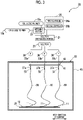
- a nonwoven fabric material 10a is formed by a nonwoven fabric manufacturing facility 20 shown in Fig. 3 .
- the nonwoven fabric manufacturing facility 20 is for forming fibers 11a and 11b and for manufacturing a nonwoven fabric material 10a which is a material of the nonwoven fabric 10 using an electric field spinning method.
- the fibers 11a form a dense layer member 14a
- the fibers 11b form a coarse layer member 12a.
- the nonwoven fabric manufacturing facility 20 includes a solution preparation portion 21 and c.
- the details of the nonwoven fabric manufacturing device 22 are shown in another drawing, and in Fig. 4 or 5 , only a part of the nonwoven fabric manufacturing device 22 is shown.
- the nonwoven fabric material 10a includes the dense layer member 14a and the coarse layer member 12a.
- the dense layer member 14a and the coarse layer member 12a become the dense layer portion 14 and the coarse layer portion 12, respectively, by undergoing a tension imparting step and a heating step after formation of the nonwoven fabric material 10a.
- the nonwoven fabric manufacturing facility 20 forms the dense layer member 14a or the coarse layer member 12a, which is a first layer material (first collecting step).
- the facility forms the coarse layer member 12a or the dense layer member 14a, which is a second layer material, on the dense layer member 14a or the coarse layer member 12a formed (second collecting step), and thus the nonwoven fabric material 10a is formed.
- the dense layer member 14a or the coarse layer member 12a may be formed first, and the dense layer member 14a is preferably formed first in order to keep the void volume of the coarse layer portion higher. In this embodiment, the dense layer member 14a is formed first.
- the nonwoven fabric manufacturing facility 20 is used to form the nonwoven fabric material 10a consisting of the dense layer member 14a and the coarse layer member 12a.
- the method is not limited as long as the respective layer members can be sequentially formed by the first collecting step and the second collecting step as described above. Examples thereof include a batch manufacturing method using a nonwoven fabric manufacturing device 22 having one nozzle unit 42, and a continuous manufacturing method using a nonwoven fabric manufacturing device 22a having two nozzle units 42a and 42b.
- a cellulosic polymer 15a (first solution) forming the dense layer portion 14 is sent to the solution preparation portion 21 by a switching portion 23 to form the dense layer member 14a in the nonwoven fabric manufacturing facility 20 and the nonwoven fabric manufacturing device 22.
- a collector on which the dense layer member 14a is formed is disposed at a predetermined position, and the switching portion 23 switches the cellulosic polymer to send a cellulosic polymer 15b (second solution) forming the coarse layer portion 12 to the solution preparation portion 21 so that the coarse layer member 12a is formed on a support 28 on which the dense layer member 14a is formed.
- the nonwoven fabric material 10a is formed.
- the cellulosic polymer 15 is a generic term for the cellulosic polymers 15a and 15b. Therefore, a solution 25 contains the cellulosic polymer 15a in the formation of the dense layer member 14a, and contains the cellulosic polymer 15b in the formation of the coarse layer member 12a.
- the fibers 11 includes the fibers 11a forming the dense layer member 14a and the fibers 11b forming the coarse layer member 12a.
- the fibers 11 is a generic term for the fibers 11a and 11b.
- the solution preparation portion 21 is for preparing the solution 25 forming the fibers 11.
- the solution preparation portion 21 prepares the solution 25 by dissolving the cellulosic polymer 15 as a fiber material to become the fibers 11 in a solvent 26.
- the solution 25 is jetted from each of nozzles 27a to 27c to be described later to form the fibers 11 on the support 28. In the following description, in a case where the nozzles 27a, 27b, and 27c are not distinguished, the nozzle 27 is written.
- the evaporation rate of the solvent 26 is represented by V (unit: ml/s, milliliters/sec)
- the evaporation rate V and the average diameter Df of the fibers 11 formed on the support 28 satisfy 1 ⁇ V/Df ⁇ 10. 2 ⁇ V/Df ⁇ 9 is more preferable, and 3 ⁇ V/Df ⁇ 8 is even more preferable.
- V/Df is adjusted in the above range by adjusting at least one of the evaporation rate V or the average diameter Df.
- the evaporation rate V is obtained by Expression (1).
- C represents the concentration (unit: %) of the solution 25.
- M1 represents the mass of the cellulosic polymer 15
- M2 represents the mass of the solvent 26.
- Q represents the jet amount of the solution 25 from the nozzle 27 (the volume of the solution jetted per hour, unit: ml/h, milliliters/hour).
- ⁇ 2 represents the density of the solution 25 (unit: g/ml).
- the evaporation rate V can be adjusted by increasing or reducing at least one of the concentration C, the jet amount Q, or the density p2.
- the evaporation rate V can also be adjusted by adjusting the recipe of the solvent 26 (for example, the component ratio in a case where a mixture of a plurality of components is used as the solvent 26).
- the average diameter Df can be adjusted by increasing or reducing at least one of the jet amount Q, the concentration C, an applied voltage to be described later, or a distance L from the nozzle 27 to the support 28.
- the evaporation rate V is obtained at a temperature of 25°C, that is substantially the same as that of the spinning space.
- V 1 ⁇ 0.01 C ⁇ Q ⁇ 10 ⁇ 3 / 3600 ⁇ ⁇ 2
- the solvent 26 may be formed of one kind of compound or two or more kinds of compounds. Since the solvent 26 not only dissolves the fiber material, but also has a function of adjusting the evaporation rate V, the solvent is preferably a mixture formed of two or more kinds of compounds from the viewpoint of adjusting the evaporation rate V. In this example, the solvent 26 is a mixture, and contains a plurality of compounds. For example, dichloromethane is used as a first compound 26a, and methanol is used as a second compound 26b. In addition to the first compound 26a and the second compound 26b, other compounds different from the first compound 26a and the second compound 26b are used as a third compound, a fourth compound, ..., respectively, and the solvent 26 may be formed of three or more kinds of compounds.
- the boiling point of the solvent 26 is preferably 90°C or lower.
- the boiling point of a compound having the largest mass ratio is regarded as the boiling point of the solvent 26.
- the boiling point of a compound having the highest boiling point among the compounds is regarded as the boiling point of the solvent 26.
- the solvent 26 is preferably an organic compound, that is, an organic solvent.
- cellulose acylate is used as the cellulosic polymer 15
- the solvent 26 may be used alone or in combination of two or more kinds, and is preferably a mixture of two or more kinds of compounds for the reason of controlling the fiber diameter.
- the solvent 26 preferably contains dichloromethane and methanol.
- the evaporation rate V is adjusted in a case where the cellulosic polymer 15 is used, whereby the spinning is preferably performed and the fibers 11 are thus preferably formed.
- methanol, dichloromethane, chloroform, toluene, acetone, and/or tetrahydrofuran can be used for the solvent 26. These may also be used alone or in combination of two or more kinds.
- the moisture content of the fibers 11 on the support 28 is preferably 3.0% or more, that is, at least 3.0%.
- the moisture content is more preferably in a range of 3.0% or more and 10.0% or less, even more preferably in a range of 4.0% or more and 9.0% or less, and particularly preferably in a range of 5.0% or more and 8.0% or less.
- the nonwoven fabric manufacturing facility 20 includes pipes 33a to 33c connecting the solution preparation portion 21 and the nonwoven fabric manufacturing device 22, and the nonwoven fabric manufacturing device 22 has nozzles 27a to 27c disposed in a state of being separated from each other.
- the pipes 33a to 33c are for introducing the solution 25.
- the pipe 33a connects the solution preparation portion 21 and the nozzle 27a
- the pipe 33b connects the solution preparation portion 21 and the nozzle 27b
- the pipe 33c connects the solution preparation portion 21 and the nozzle 27c.
- the solution 25 is discharged from each of the nozzles 27a to 27c.
- the solution 25 discharged from each of the nozzles 27a to 27c forms the fibers 11.
- the pipe 33 is written.
- a long support 28 is used for collecting and depositing (hereinafter, collectively referred to as accumulating) the fibers 11 and for supporting the nonwoven fabric material 10a, and the support 28 is moved in a longitudinal direction.
- the details of the support 28 will be described later using another drawing.
- the lateral direction in Fig. 3 is a width direction of the support 28, and the depth direction in Fig. 3 is a moving direction of the support 28.
- the nozzles 27a to 27c are arranged in this order in the width direction of the support 28. In this example, three nozzles 27 are provided, but the number of nozzles 27 is not limited thereto.
- Each of the pipes 33a to 33c is provided with a pump 38 which sends the solution 25 to the nozzle 27. By changing the rotation speed of the pump 38, the jet amount of the solution 25 discharged from each of the nozzles 27a to 27c is adjusted.
- the nozzles 27a to 27c are held by a holding member 41.
- the holding member 41 and the nozzle 27 constitute a nozzle unit 42 of the nonwoven fabric manufacturing device 22.
- Fig. 4 shows the device viewed from the side of the nozzle 27a of Fig. 3 , and only the nozzle 27a is shown as the nozzle 27.
- the nonwoven fabric manufacturing device 22 includes a chamber 45, the above-described nozzle unit 42, an accumulating portion 50, a power source 51, and the like.
- the chamber 45 houses, for example, the nozzle unit 42, a part of the accumulating portion 50, and the like.
- the chamber 45 can be hermetically sealed, and thus prevents a solvent gas from leaking outside.
- the solvent gas is formed by vaporization of the solvent 26 of the solution 25.
- the chamber 45 includes a humidity adjusting mechanism 45a which adjusts the internal relative humidity (hereinafter, simply referred to as humidity).
- the humidity adjusting mechanism 45a sends a gas whose humidity has been adjusted (for example, air) to the chamber 45 to recover the atmosphere in the chamber 45. After that, the mechanism adjusts the humidity, and then sends the gas again to the chamber 45. In this way, the humidity inside the chamber 45 is adjusted.
- the humidity adjustment is performed to adjust the humidity of the above-described spinning space. That is, the chamber 45 also has a function of partitioning the spinning space from the external space, thereby adjusting the humidity of the spinning space.
- the adjustment of the humidity of the spinning space is not limited to the method using the chamber 45 in this example.
- the humidity of the spinning space may be adjusted by a chamber defining the spinning space in the chamber 45.
- the humidity of the spinning space is preferably 10% or more and 30% or less.
- the humidity may change during the formation of the fibers 11 and the manufacturing of the nonwoven fabric material 10a as long as it is in the above range.
- the humidity of the spinning space is more preferably in a range of 15% or more and 25% or less.
- the nozzle unit 42 is disposed in an upper portion in the chamber 45.
- a tip end of the nozzle 27 from which the solution 25 is discharged is directed toward a collector 52 disposed below the nozzle 27 in Fig. 4 .
- the solution 25 forms a substantially conical Taylor cone 53 at the tip end opening.
- the accumulating portion 50 is disposed below the nozzle 27.
- the accumulating portion 50 has a collector 52, a collector rotating portion 56, a support supply portion 57, and a support winding portion 58.
- the collector 52 is for attracting the solution 25 discharged from the nozzle 27 and for collecting the formed fiber 11 as a part of the nonwoven fabric material 10a.
- the dense layer member 14a which is a first layer material is collected on the support 28 to be described later, and then the coarse layer member 12a which is a second layer material is collected on the first layer material.
- the collector 52 is formed of an endless belt composed of a metal strip formed in an annular shape.
- the collector 52 may be made of a material charged by applying a voltage by the power source 51, and is made of, for example, stainless steel.
- the collector rotating portion 56 includes a pair of rollers 61 and 62, a motor 60, and the like.
- the collector 52 is horizontally hung on the pair of rollers 61 and 62.
- the motor 60 disposed outside the chamber 45 is connected to the shaft of one roller 61 to rotate the roller 61 at a predetermined speed. Due to the rotation, the collector 52 is moved and circulated between the rollers 61 and 62.
- the moving speed of the collector 52 is, for example, 0.2 m/min, but is not limited thereto.
- a support 28 consisting of, for example, a strip-shaped aluminum sheet is supplied to the collector 52 by the support supply portion 57.
- the support 28 is for accumulating the fibers 11 and for obtaining the nonwoven fabric material 10a.
- the support supply portion 57 has a delivery shaft 57a.
- a support roll 63 is mounted on the delivery shaft 57a.
- the support roll 63 has a configuration in which the support 28 is wound around a winding core 64.
- the support winding portion 58 has a winding shaft 67.
- the winding shaft 67 is rotated by a motor (not shown), and the support 28 on which the nonwoven fabric material 10a is formed is wound around a set winding core 68.
- the nonwoven fabric manufacturing device 22 has a function of forming the fibers 11 and a function of forming the nonwoven fabric material 10a.
- the support 28 may be placed on the collector 52 and moved by moving the collector 52.
- the nonwoven fabric material 10a may be formed by directly accumulating the fibers 11 on the collector 52. However, the nonwoven fabric material 10a may be stuck and difficult to peel off depending on the material forming the collector 52, the surface condition of the collector 52, or the like. Therefore, as in this embodiment, a support 28 to which the nonwoven fabric material 10a is hard to stick is preferably introduced onto the collector 52 to accumulate the fibers 11 on the support 28.
- the power source 51 is a voltage applying portion which applies a voltage to the nozzle 27 and the collector 52 to charge the nozzle 27 to a first polarity and to charge the collector 52 to a second polarity reverse to the first polarity.
- the solution 25 is charged by passing through the charged nozzle 27, and is discharged from the nozzle 27 while being charged.
- the holding member 41 and the nozzle 27 are electrically connected, and by connecting the power source 51 to the holding member 41, a voltage is applied to the nozzle 27 via the holding member 41.
- the method of applying a voltage to the nozzle 27 is not limited thereto.
- a voltage may be applied to each nozzle 27 by connecting the power source 51 to each nozzle 27.
- the nozzle 27 is positively (+) charged and the collector 52 is negatively (-) charged.
- the polarities of the nozzle 27 and the collector 52 may be opposite.
- the collector 52 may be grounded to have a potential of 0. Due to the charging, the solution 25 is ejected as a spinning jet 69 from the Taylor cone 53 toward the collector 52.
- the solution 25 is charged by applying a voltage to the nozzle 27.
- the solution 25 may be charged in the pipe 33, and the charged solution 2 may be introduced to the nozzle 27.
- a distance L between the nozzle 27 and the collector 52 varies depending on the kinds of the cellulosic polymer 15 and the solvent 26, the mass ratio of the solvent 26 in the solution 25, or the like, and is preferably in a range of 30 mm or more and 500 mm or less. In this embodiment, the distance L is, for example, 150 mm.
- the voltage (applied voltage) which is applied to the nozzle 27 and the collector 52 is preferably 5 kV or more and 200 kV or less. From the viewpoint of making the fibers 11 thinner, the applied voltage is preferably as high as possible in the above range. In this embodiment, the voltage is, for example, 40 kV.
- the fibers 11b are not collected on the collector 52 or the support 28, but collected on the dense layer member 14a formed on the collector 52 or the support 28. Therefore, the conditions such as the applied voltage in the electric field spinning may be different from those in a case where the fibers 11a forming the dense layer portion 14 are collected.
- the fibers 11a are formed on the surface of the collector 52 or the support 28 by the use of the cellulosic polymer 15a forming the dense layer member 14a.
- the fibers 11a forming the dense layer member 14a are formed to have a desired length on the support 28 in the transport direction, and then the support 28 on which the dense layer member 14a is formed is disposed on the upstream side of the movement of the collector 52 of the nonwoven fabric manufacturing device 22.
- the collector 52 or the support 28 is returned and disposed on the upstream side in the moving direction of the collector 52 in a desired distance by reversing the transport direction.
- the switching portion 23 switches the cellulosic polymer 15 to the cellulosic polymer 15b, and then the fibers 11b are formed again using the same nonwoven fabric manufacturing facility 20.
- the two nozzle units 42a and 42b are installed side by side in the transport direction of the collector 52.
- the cellulosic polymer 15a (first solution) forming the dense layer member 14a is sent to the solution preparation portion 21 by the nozzle unit 42a at the front part in the transport direction to form the dense layer member 14a (first collecting step).
- the cellulosic polymer 15b (second solution) forming the coarse layer portion 12 is sent to the solution preparation portion 21 by the nozzle unit 42b installed behind the nozzle unit 42a in the transport direction to form the coarse layer member 12a (second collecting step).
- the fibers 11a, the fibers 11b, and the nonwoven fabric 10 are formed in the same manner as in the above description.
- a tension imparting step of imparting a tension in the in-plane direction of the nonwoven fabric material 10a including the dense layer member 14a (first layer material) and the coarse layer member 12a (second layer material) formed, and a heating step of heating the nonwoven fabric material 10a to which the tension is imparted are performed.
- the tension imparting step is a step of imparting a tension in the in-plane direction of the obtained nonwoven fabric material 10a.
- a tension is imparted in the in-plane direction of the obtained nonwoven fabric material 10a, that is, in the X-Y direction in Fig. 1 .
- the tension is preferably imparted evenly in the in-plane direction.
- the tension to be imparted can be appropriately set according to the application or the like, and is preferably suppressed to be small so that the nonwoven fabric material 10a has neither wrinkles nor sagging, and thus the area of the nonwoven fabric material 10a (the area of the surface along the X-Y plane) is not changed as much as possible.
- Any method can be used as the method of imparting a tension as long as the tension can be imparted evenly in the in-plane direction of the nonwoven fabric material 10a.
- Specific examples thereof include a method in which an end portion of the nonwoven fabric material 10a cut into a desired shape is nipped by clips at substantially equal intervals and the clips are fixed so that a tension is imparted in the in-plane direction of the obtained nonwoven fabric material 10a, and a method in which the nonwoven fabric material 10a cut into a desired shape such as a circular shape is held by a frame.
- the frame is a tension imparting member which imparts a tension to the nonwoven fabric material 10a.
- the frame has a circular shape in which the nonwoven fabric material 10a is held in a state in which the nonwoven fabric material 10a is exposed at the center, but the tension imparting member is not limited to the frame as long as the above-described tension can be imparted so that the area of the nonwoven fabric material 10a is not changed.
- the tension imparting member preferably holds the entire periphery of the nonwoven fabric material 10a, rather than a part of the periphery.
- the heating step is performed on the nonwoven fabric material 10a to which the tension is imparted.
- the heating step is a step of forming the nonwoven fabric 10 by applying heat to the nonwoven fabric material 10a in a state in which the tension is imparted.
- the heating step is preferably performed so that the nonwoven fabric 10 is heated in a state in which the tension is imparted, and the number of fusion points in the dense layer portion 14 is in the above specific range.
- the heating step uses, for example, a temperature adjusting device.
- the temperature adjusting device includes a storage portion and a temperature control mechanism which adjusts the temperature of the storage portion.
- the heating step can be performed by housing the nonwoven fabric material 10a held by clips, a frame, or the like in a state in which the tension is imparted in the housing portion including the temperature control mechanism of the temperature adjusting device, and heating the nonwoven fabric material 10a via the housing portion.
- the fibers 11 are adhered to each other in the nonwoven fabric material 10a whose temperature has been increased by heating the nonwoven fabric material 10a in a state in which the tension is imparted, and thus the nonwoven fabric 10 is obtained.
- the heating step time is preferably in a range of 10 seconds or longer and 1,200 seconds or shorter, and more preferably in a range of 30 seconds or longer and 900 seconds or shorter.
- the heating step time is a period of time in which the temperature of the nonwoven fabric material 10a is maintained to a set temperature.
- the melting point of the cellulosic polymer 15 is represented by Tm (unit: °C), and the glass transition point is represented by Tg (unit: °C).
- the nonwoven fabric material 10a is preferably heated to a temperature of Tg or higher and Tm or lower.
- the fibers 11 are softened and more easily fused to each other (adhered by melting) than in a case where the nonwoven fabric material is heated to a temperature lower than Tg.
- the melting point of the cellulosic polymer 15a is preferably lower than the melting point of the cellulosic polymer 15b, and a difference between the melting points is preferably 10 degrees or more. The difference is more preferably 20 degrees or more, and even more preferably 30 degrees or more.
- the void volume Pc is at least 90% and the average pore diameter Dc is in a range of 0.5 ⁇ m or more and 50 ⁇ m or less
- the void volume Pd is at least 70% and the relative standard deviation of pore diameter distribution is 20% or less
- the void volume Pc of the coarse layer portion and the void volume Pd of the dense layer portion satisfy a relationship of Pc>Pd
- the average pore diameter Dc of the coarse layer portion and the average pore diameter Dd of the dense layer portion satisfy a relationship of Dc>Dd.
- a cooling step is preferably performed after the heating step. That is, the nonwoven fabric 10 obtained in the heating step is preferably cooled in a state in which the tension is imparted (cooling step). Accordingly, a predetermined pore ratio of the nonwoven fabric 10 is more likely to be maintained to the state immediately after the heating step. The tension is preferably released after the cooling step.
- the fibers 11b are fused to each other especially in the dense layer portion 14a.
- the heating step is preferably performed so that the number of fusion points in the dense layer portion 14 is in the above specific range.
- the fibers 11a may not be fused to each other in the heating step by adjusting the cellulosic polymer 15b to be used.
- a hydrophilization step may be performed on the nonwoven fabric material 10a or the nonwoven fabric 10.
- the hydrophilization step is a step of imparting hydrophilicity to the nonwoven fabric material 10a or the nonwoven fabric 10.
- hydrophilicity imparting step By imparting hydrophilicity to the nonwoven fabric material 10a or the nonwoven fabric 10 in the hydrophilicity imparting step, in a case where the nonwoven fabric 10 is used as a filter, compatibility between the filter and an aqueous solution is improved, and this leads to an improvement in filtration speed.
- CWST can be kept in a specific range.
- the hydrophilization step may be performed on the nonwoven fabric material 10a before the tension imparting step.
- the hydrophilization step may be performed on the nonwoven fabric 10 after the heating step.
- a saponification treatment step can be performed on the nonwoven fabric material 10a or the nonwoven fabric 10 as the hydrophilization step.
- the saponification treatment is performed by bringing a saponification solution into contact with the nonwoven fabric material 10a or the nonwoven fabric 10. Therefore, specifically, the saponification treatment can be performed by a method such as immersion of the nonwoven fabric material 10a or the nonwoven fabric 10 in the saponification solution or spraying of the saponification solution onto the nonwoven fabric material 10a or the nonwoven fabric 10.
- the saponification solution contains alkali.
- the alkali is potassium hydroxide (KOH), but is not limited thereto.
- Sodium hydroxide (NaOH) may be used instead of KOH.
- the saponification solution contains a solvent in addition to the alkali.
- the solvent includes water and organic solvents.
- the organic solvent one or more kinds selected from the group consisting of alcohols, ethers, amides, and sulfoxides can be used.
- the alcohols alcohols having 2 or more and 8 or less carbon atoms are preferable.
- Examples of the alcohols having 2 or more and 8 or less carbon atoms include ethanol, isopropyl alcohol, 1-propanol, 1-butanol, hexanol, ethylene glycol, glycerin, propylene glycol, butylene glycol, and pentaerythritol.
- isopropyl alcohol is particularly preferable, and is also used in this embodiment.
- the ethers include diethyl ether, diethylene glycol, dipropylene glycol, ethylene glycol monomethyl ether, ethylene glycol monoethyl ether, diethylene glycol monomethyl ether, diethylene glycol monoethyl ether, and propylene glycol monomethyl ether.
- Examples of the amides include N,N-dimethylformamide and dimethylacetamide.
- Examples of the sulfoxides include dimethylsulfoxide.
- the operations of the nonwoven fabric manufacturing facility 20 and the nonwoven fabric manufacturing method will be described.
- a voltage is applied by the power source 51. Accordingly, the nozzle 27 is positively charged (first polarity), and the collector 52 is negatively charged (second polarity).
- the solution 25 is continuously supplied to the nozzle 27 from the solution preparation portion 21, and the support 28 is continuously supplied onto the moving collector 52.
- the solution 25 is positively charged (first polarity) by passing through each of the nozzles 27a to 27c, and is discharged from the tip end opening of each of the nozzles 27a to 27c while being charged.
- the collector 52 attracts the solution 25 which is discharged from the tip end opening while being charged to the first polarity. Accordingly, a Taylor cone 53 is formed at the tip end opening, and a spinning jet 69 is discharged from the Taylor cone 53 toward the collector 52.
- the spinning jet 69 which is charged to the first polarity, splits to have a smaller diameter by repulsion due to the charge of the spinning jet, and/or extends to have a smaller diameter in a spiral orbit while heading toward the collector 52, and the fibers 11 are collected on the support 28.
- the fibers 11 are deposited in an extremely short time and collected as the nonwoven fabric 10.
- the thickness of the nonwoven fabric 10 can be adjusted by increasing or reducing the deposition amount.
- the deposition amount can be increased or reduced by, for example, adjusting the moving speed of the support 28.
- a nonwoven fabric 10 in which fibers 11 having an average diameter Df in a range of 0.10 ⁇ m or more and 5.00 ⁇ m or less are formed, in the coarse layer portion 12, the void volume is 90% or more and the average pore diameter DA is in a range of 0.5 ⁇ m or more and 50 ⁇ m or less, and in the dense layer portion 14, the void volume is 70% or more and the relative standard deviation of pore diameter distribution is suppressed to 20% or less is easily obtained.
- the spinning jet 69 is thinner than in a case of V/Df ⁇ 1, and thus the solvent 26 sufficiently evaporates and the fibers 11 having an average diameter Df in the above range reach the support 28. As a result, the fibers 11 are deposited on the support 28 in a state in which the fibers do not adhere to each other or the adhesive strength therebetween is extremely small even in a case where the fibers adhere to each other.
- the spinning jet 69 forms the fibers 11 without becoming beads (microspheres) and is collected more reliably than in a case of 10 ⁇ V/Df. Since no beads are formed, no beads fill the voids 13 of the nonwoven fabric 10 on the support 28. As a result, the void volume is reliably 90% or more especially in the coarse layer portion 12.
- the humidity of the spinning space is adjusted to be 10% or more and 30% or less, the moisture content of the fibers 11 on the support 28 is reliably 3.0% or more and does not exceed 10%.
- the spinning jet 69 produced subsequently is more reliably accumulated as the fibers 11 on the support 28 than in a case where the moisture content is less than 3.0%. It is thought this is because the fibers 11 collected on the support 28 serves for a ground function to release the charge due to the moisture contained therein, and thus the spinning jet 69 produced subsequently in the spinning space heads toward the support 28 in a state in which it is suppressed so as not to be scattered therearound, forms the fibers 11, and reaches the support.
- the nonwoven fabric 10 is more reliably manufactured with a void volume of 90% or more in the coarse layer portion 12 and a void volume of 70% or more in the dense layer portion 14, along with 1 ⁇ V/FD ⁇ 10.
- the moisture content is 10% or less
- the deformation of the fibers 11 which has absorbed the moisture by their own weight is suppressed as compared to a case where the moisture content is more than 10%, and a high void volume is easily maintained.
- the fibers 11 forms a nonwoven fabric 10 consisting of a specific coarse layer portion 12 and a specific dense layer portion 14, and is sent to the support winding portion 58 together with the support 28.
- the nonwoven fabric 10 is wound around the winding core 68 in a state of being overlapped with the support 28. After the winding core 68 is removed from the winding shaft 67, the nonwoven fabric 10 is separated from the support 28.
- the nonwoven fabric 10 thus obtained is long, and may be then cut into, for example, a desired size.
- the collector 52 a belt which is moved and circulated is used as the collector 52, but the collector is not limited to the belt.
- the collector may be a fixed flat plate or a cylindrical rotating body. Even in the case of a collector consisting of a flat plate or a cylindrical body, the support 28 is preferably used so that the nonwoven fabric 10 can be easily separated from the collector.
- a tubular sheet material consisting of fibers is formed on a peripheral surface of the rotating body. Accordingly, the tubular sheet material may be removed from the rotating body after spinning, and cut into a desired size and shape.
- the nozzle 27 is disposed in a posture in which the tip end opening thereof is directed downward, and the collector 52 is disposed below the nozzle 27 to jet the solution 25 downward.
- the jet direction of the solution 25 is not limited to this example.
- the nozzle 27 may be disposed in a posture in which the tip end opening thereof is directed upward, and the collector 52 may be disposed above the nozzle 27 to jet the solution 25 upward.
- Nonwoven fabrics 10 were manufactured using a sheet material forming facility 20 ( Fig. 3 ) and a temperature adjusting device, and used as Examples 1 to 7. That is, using one nonwoven fabric manufacturing facility 20, a nonwoven fabric material 10a including a coarse layer portion 12 and a dense layer portion 14 was manufactured by switching between a cellulosic polymer 15a forming the dense layer portion 14 and a cellulosic polymer 15b forming the coarse layer portion 12 with a switching portion 23. The manufactured nonwoven fabric material 10a was cut into a circular shape. An edge portion thereof was nipped by clips at several places so that no wrinkles or sagging occurred, and the clips were fixed to a circular frame to impart a tension to the nonwoven fabric material 10a (tension imparting step). Then, in a case where a heating treatment was performed, heating was performed by a heating treatment device (heating step). After heating, cooling was performed to perform various measurements.
- a heating treatment device heating treatment device
- the cellulosic polymer 15 used was written in the column "Material” in Table 1.
- TAC cellulose triacetate
- DAC a case where the cellulose acylate was cellulose diacetate
- CAP a case where the cellulose acylate was cellulose acetate propionate whose acyl group was a propionyl group
- CAB a case where the cellulose acylate was cellulose acetate butyrate whose acyl group was a butanoyl group
- CAB was written.
- As the materials Cellulose Acetate Propionate and Cellulose Acetate Butyrate manufactured by Eastman Chemical Company were used.
- a solvent 26 was a mixture of dichloromethane and methanol as described above in any case, and the mass ratio of dichloromethane:methanol was 87:13.
- the concentration of the cellulosic polymer 15 in a solution 25 was 8 mass% in any case. This concentration was obtained by ⁇ M1/(M1+M2) ⁇ 100 in a case where the mass of the cellulosic polymer 15 was represented by M1 and the mass of the solvent 26 was represented by M2.
- the number of fusion points in the dense layer portion 14 the value measured by the above-described method was written in the column "Number of Fusion Points" in Table 1.
- the number of fusion points in the dense layer portion 14 was 67/mm 2 .
- the number of fusion points in the dense layer portion 14 after the heating step was in a range of 2,000/mm 2 or more and less than 10,000/mm 2 .
- the filtration service life and filtration accuracy of the obtained nonwoven fabric 10 were evaluated.
- evaluation of the filtration service life the value of CWST was measured, and the result was written in the column "CWST".
- the following filtration service life evaluation was performed.
- the filtration service life evaluation method and the evaluation standards are as follows. The evaluation results are shown in Table 1.
- CWST was measured using an aqueous solution of calcium chloride, an aqueous solution of sodium hydroxide, and a mixed liquid of water and ethanol. 10 drops of each of the above-described aqueous solutions having different surface tensions were gently placed on a first surface 10A, which was the coarse layer surface of the nonwoven fabric 10 held horizontally, and were left for 10 minutes. In a case where 9 or more drops out of 10 drops moistened the surface, the nonwoven fabric 10 was judged to be moistened with the solution having that surface tension, and in a case where 2 or more drops out of 10 drops did not moisten the surface, the nonwoven fabric 10 was judged to be not moistened with the solution having that surface tension. An average of the surface tensions of the solution which moistened the surface and the surface tension of the solution which did not moisten the surface was defined as CWST of the nonwoven fabric 10.
- the nonwoven fabric 10 was attached to a stainless line holder (KS-47 manufactured by Advantec Co., Ltd.), and an aqueous solution prepared by dispersing 0.1 mass% of crosslinked acrylic polydisperse particles (manufactured by Soken Chemical & Engineering Co., Ltd.) having an average particle diameter of 10 ⁇ m in pure water was flowed from the coarse layer portion 12 and filtered.
- a pressure gauge manufactured by KEYENCE CORPORATION
- the transmittance of particles calculated was evaluated according to the following standards. A, B, and C represent pass, and D represents fail.
- Nonwoven fabrics 10 were prepared in the same manner as in Example 1, except that the materials and/or the manufacturing method to be used were changed.
- the used polymer was written in the column “Material” in Table 1.
- PP polypropylene
Landscapes
- Engineering & Computer Science (AREA)
- Textile Engineering (AREA)
- Chemical & Material Sciences (AREA)
- Chemical Kinetics & Catalysis (AREA)
- Mechanical Engineering (AREA)
- Nonwoven Fabrics (AREA)
- Filtering Materials (AREA)
- Laminated Bodies (AREA)
Abstract
Description
- The present invention relates to a nonwoven fabric, a nonwoven fabric manufacturing method, and a filter.
- Nonwoven fabrics formed of fibers have been known. Examples of the fiber include so-called nanofibers having a nano-order diameter of several nanometers or more and less than 1,000 nanometers, so-called micron fibers having a micrometer-order diameter of several micrometers or more and less than 1,000 micrometers, and so-called submicron fibers mainly having a submicron-order diameter of 10-1 micrometers or more and less than several micrometers.
- A fiber structure having a layer consisting of fibers such as a nonwoven fabric is used as a filter or the like. For example,
JP2013-236986A - An electric field spinning method has been known as a method of manufacturing fibers such as submicron fibers and a nonwoven fabric formed of such fibers. The electric field spinning method is also called an electrospinning method or the like, and is performed using, for example, an electric field spinning device (also called an electrospinning device) having a nozzle, a collector, and a power source. In a general electric field spinning device, a voltage is applied between a nozzle and a collector by a power source to, for example, negatively charge the nozzle and positively charge the collector.
- In a case where a solution as a raw material is discharged from the nozzle in a state in which a voltage is applied, a conical protrusion called a Taylor cone, composed of the solution, is formed in an opening at a tip end of the nozzle. In a case where the applied voltage is gradually increased and a Coulomb force exceeds a surface tension of the solution, the solution flies out from a tip end of the Taylor cone, and a spinning jet is formed. The spinning jet is moved to the collector by a Coulomb force and is collected as fibers on the collector, and a nonwoven fabric formed of the fibers is formed on the collector.
- In the tubular filter disclosed in
JP2013-236986A - A high void volume of a nonwoven fabric leads to an improvement in filtration service life of a filter formed of the nonwoven fabric. However, the nonwoven fabric used as the above tubular filter does not have a high void volume of 90% or more. In addition, in the above tubular filter, in order to realize the filtration accuracy, it is necessary to use a filtration layer formed by preparing three kinds of nonwoven fabrics, and then connecting and winding the fabrics. Therefore, with a nonwoven fabric which can be used as a filter realizing excellent filtration accuracy by a simpler structure and having more excellent filtration service life, it is possible to expect further expansion of applications from the viewpoint of cost and performance.
- Therefore, an object of the present invention is to provide a nonwoven fabric having excellent filtration accuracy and filtration service life in a case where it is used as a filter, a nonwoven fabric manufacturing method, and a filter.
- A nonwoven fabric according to an aspect of the present invention is formed of fibers having an average diameter in a range of 0.10 µm or more and 5.00 µm or less. The nonwoven fabric includes a coarse layer portion and a dense layer portion having different void volumes. In the coarse layer portion, a void volume Pc is at least 90% and an average pore diameter Dc is in a range of 0.5 µm or more and 50 µm or less. In the dense layer portion, a void volume Pd is at least 70% and a relative standard deviation of pore diameter distribution is 20% or less. The void volume Pc of the coarse layer portion and the void volume Pd of the dense layer portion satisfy a relationship of Pc>Pd, and the average pore diameter Dc of the coarse layer portion and an average pore diameter Dd of the dense layer portion satisfy a relationship of Dc>Dd.
- It is preferable that the dense layer portion has a fusion point at which the fibers are fused to each other, and the number of fusion points is 500/mm2 or more.
- It is preferable that a surface on the coarse layer portion side has a critical wettable surface tension of 70 mN/m or more.
- It is preferable that the fibers are made of a cellulosic polymer. In addition, it is preferable that the fibers are made of cellulose acylate.
- It is preferable that in the coarse layer portion, the fibers are made of cellulose triacetate or cellulose diacetate. It is preferable that in the dense layer portion, the fibers are made of cellulose acetate propionate or cellulose acetate butyrate.
- It is preferable that the fibers are continuous fibers.
- It is preferable that the coarse layer portion and the dense layer portion are formed continuously and integrated with each other.
- In addition, in a nonwoven fabric manufacturing method according to an aspect of the present invention, a voltage is applied between a solution prepared by dissolving a fiber material in a solvent and a collector, and fibers formed by ejecting the solution from a nozzle are collected on a surface of the collector. The nonwoven fabric manufacturing method includes a first collecting step, a second collecting step, a tension imparting step, and a heating step. In the first collecting step, fibers formed using a first solution as the solution are collected to form a first layer material. In the second collecting step, following the first collecting step, fibers formed using a second solution different from the first solution as the solution are collected to form a second layer material. In the tension imparting step, a tension is imparted in an in-plane direction of a nonwoven fabric material including the first layer material and the second layer material. In the heating step, the nonwoven fabric material to which the tension is imparted is heated to form a first layer from the first layer material and/or to form a second layer from the second layer material.
- It is preferable that the fiber material is a cellulosic polymer. In addition, it is preferable that the fiber material is made of cellulose acylate.
- It is preferable that in the first solution, the fiber material is cellulose triacetate or cellulose diacetate. It is preferable that in the second solution, the fiber material is cellulose acetate propionate or cellulose acetate butyrate.
- It is preferable that in the first solution, the fiber material is cellulose triacetate, and in the second solution, the fiber material is cellulose acetate propionate or cellulose acetate butyrate.
- It is preferable that the solvent is a mixture of a plurality of compounds.
- It is preferable that the solvent contains dichloromethane and methanol.
- It is preferable that a hydrophilization step of performing saponification is included.
- In addition, a filter according to an aspect of the present invention is formed of the nonwoven fabric according to any one of the above items, and includes: a coarse layer portion as one surface; and a dense layer portion as the other surface.
- According an aspect of the present invention, it is possible to provide a nonwoven fabric having excellent filtration accuracy and filtration service life in a case where it is used as a filter, a nonwoven fabric manufacturing method, and a filter.
-
-
Fig. 1 is a schematic perspective view of a part of a nonwoven fabric according to an embodiment. -
Fig. 2 is a cross-sectional view schematically showing a configuration of an example of the nonwoven fabric. -
Fig. 3 is a schematic view of a nonwoven fabric manufacturing facility. -
Fig. 4 is a schematic view of an example in which one nonwoven fabric manufacturing device is used. -
Fig. 5 is a schematic view of an example in which two nonwoven fabric manufacturing devices are used. - A
nonwoven fabric 10 according to this embodiment shown inFig. 1 is formed offibers 11. In thenonwoven fabric 10, a plurality ofvoids 13 as spatial domains defined by thefibers 11 are formed as a part in which air exists. In this way, thenonwoven fabric 10 contains air inside. InFig. 1 , only a part of thenonwoven fabric 10 in a thickness direction Z on the side of one surface (hereinafter, referred to as a first surface) 10A is drawn to avoid the complication of the drawing. Therefore, thenonwoven fabric 10 has a structure in which a large number of thefibers 11 further overlap on the lower side ofFig. 1 in the thickness direction Z. Thenonwoven fabric 10 includes two layer portions, a coarse layer portion and a dense layer portion which are different in shape of thevoids 13 and the like in the thickness direction Z. In this embodiment, the coarse layer portion and the dense layer portion are formed continuously with no break, and thenonwoven fabric 10 is formed as an integrated body. - In a case where the plurality of
voids 13 communicate with each other in the thickness direction Z of thenonwoven fabric 10, these form through holes in the thickness direction Z of thenonwoven fabric 10. The holes function as filter holes in a case where thenonwoven fabric 10 is used as, for example, a filter. In addition, somevoids 13 do not form holes, and exist as, for example, non-through spatial domains in the thickness direction Z, closed by thefibers 11. In a case where thenonwoven fabric 10 is used as a filter, the spatial domain also has a function of capturing and fractionating a substance having a specific size or the like. - The
nonwoven fabric 10 may include thefibers 11, and may include other fibers made of different materials in addition to thefibers 11. InFig. 1 , thefirst surface 10A is drawn along the X-Y plane, and the Z-direction orthogonal to the X-Y plane is defined as the thickness direction of thenonwoven fabric 10. - As shown in
Fig. 2 , thenonwoven fabric 10 includes at least two layer portions, acoarse layer portion 12 and adense layer portion 14 having different void volumes in the thickness direction Z. The void volume refers to the volume percent of air contained in the nonwoven fabric. Although thecoarse layer portion 12 and thedense layer portion 14 have different void volumes, thecoarse layer portion 12 and thedense layer portion 14 are formed continuously with no break. Therefore, it is thought that thenonwoven fabric 10 is formed as an integrated body, and in aboundary portion 16 between thecoarse layer portion 12 and thedense layer portion 14, there is a part where both the layer portions are mixed. - The
fibers 11 are formed to have a substantially constant diameter D1 (Fig. 1 ). An average (hereinafter, referred to as an average diameter) Df of diameters D1 (unit: µm) is in a range of 0.10 µm or more and 5.00 µm or less. In a case where the average diameter Df is 0.10 µm or more, the detachment of fiber pieces is suppressed as compared to a case where the average diameter is less than 0.10 µm. Suppression of the detachment of fiber pieces means that the detachment of fiber pieces from thenonwoven fabric 10 is suppressed, and suppression of the detachment of fiber pieces leads to excellent durability of thenonwoven fabric 10. - In a case where the average diameter Df is 5.00 µm or less, the void volume of the whole
nonwoven fabric 10 is larger than in a case where the average diameter is more than 5.00 µm. Thus, a filtration processing amount in a case where the nonwoven fabric is used as a filter is increased, and the filtration service life is improved. The filtration service life means that the filtration capacity is large as a whole due to the fact that the processing amount per unit time is large and/or constant filtration performance is maintained over a long time by maintaining a state in which clogging is suppressed. In addition, due to the increased void volume, for example, sound absorbing performance or heat insulating performance in a case where the nonwoven fabric is used as a sound absorbing material or a heat insulating material is increased. In addition, in a case where the average diameter Df is 5.00 µm or less, thenonwoven fabric 10 is softer even with the same void volume and is used for wider applications than in a case where the average diameter is more than 5.00 µm. The average diameter of thefibers 11 is more preferably in a range of 0.15 µm or more and 4.00 µm or less, and even more preferably in a range of 0.20 µm or more and 3.00 µm or less. - The average diameter Df can be obtained by measuring diameters of 100
fibers 11 from an image taken by a scanning electron microscope and calculating an average value. - In addition, the
fibers 11 are preferably continuous fibers. The continuous fibers mean fibers having an aspect ratio, that is a ratio of a length of the fiber in an axial direction to a diameter of the fiber, of 100 or more. Thefibers 11 according to this embodiment are substantially continuous fibers, and thecontinuous fibers 11 form thenonwoven fabric 10 by being folded in the thickness direction. Substantially continuous fibers do not mean that all thefibers 11 have an aspect ratio of 100 or more, but mean thatmost fibers 11 are long continuous fibers having an aspect ratio of 100 or more even in a case where there may be short fibers having an aspect ratio of 100 or less in thefibers 11. - In the
nonwoven fabric 10, thecoarse layer portion 12 has a void volume Pc of at least 90%, that is, 90% or more. Thenonwoven fabric 10 including a part having an extremely high void volume Pc as described above has improved filtration service life in a case where the nonwoven fabric is used as a filter, as compared to a case where the nonwoven fabric does not include a part having such a high void volume Pc. In addition, in a case where thenonwoven fabric 10 includes a part having a void volume Pc of 90% or more, the nonwoven fabric contains a large amount of air inside and is soft. Since a large amount of air is contained as described above, the nonwoven fabric is used for wider applications than in a case where it does not contain a part having a void volume Pc of 90% or more. For example, the nonwoven fabric can be used as a sound absorbing material or a heat insulating material since it exhibits excellent sound absorbing performance and heat insulating performance. - The void volume Pc of the
coarse layer portion 12 is preferably 99.8% or less from the viewpoint that thenonwoven fabric 10 secures higher durability. The void volume Pc of thecoarse layer portion 12 is more preferably in a range of 90% or more and 99.8% or less, even more preferably in a range of 95% or more and 99.6% or less, and particularly preferably in a range of 97% or more and 99.4% or less. - In the
nonwoven fabric 10, thedense layer portion 14 has a void volume Pd of at least 70%, that is, 70% or more. The void volume Pc of thecoarse layer portion 12 and the void volume Pd of thedense layer portion 14 satisfy a relationship of Pc>Pd. In thenonwoven fabric 10, in a case where thedense layer portion 14 combined with thecoarse layer portion 12 has such a specific void volume Pd, the filtration accuracy and the filtration service life in a case where the nonwoven fabric is used as a filter are improved. The filtration accuracy is a measure for blocking solids of a specific size, and also includes excellent size separation performance. In a case where thenonwoven fabric 10 is used as a filter, for example, a liquid to be filtered passes through the filter from thecoarse layer portion 12. - The void volume Pd of the
dense layer portion 14 is preferably 99.8% or less from the viewpoint that thenonwoven fabric 10 secures higher durability. The void volume Pd of thedense layer portion 14 is more preferably in a range of 70% or more and 99.8% or less, even more preferably in a range of 80% or more and 99.6% or less, and particularly preferably in a range of 90% or more and 99.4% or less. - In a case where a weighing capacity is represented by W (unit: g/m2) and a thickness is represented by H (unit: mm) in each of the
coarse layer portion 12 and thedense layer portion 14 of thenonwoven fabric 10, and a specific gravity of thefibers 11 is represented by ρ1 (unit: kg/m3), the void volume (unit: %) can be obtained by [1-{(W/1000)/(H/1000)}/ρ1]×100. Thecoarse layer portion 12 or thedense layer portion 14 of thenonwoven fabric 10 is cut into a 5 cm × 5 cm piece, a mass thereof is measured by an electronic balance (manufactured by METTLER TOLEDO), and a value obtained by converting the measured value per m2 is used as the weighing capacity W. In this example, the thickness H is measured by a noncontact laser displacement gauge (LK-H025 manufactured by KEYENCE CORPORATION). - In the
nonwoven fabric 10, thefibers 11 are intertwined and integrated with each other. In theboundary portion 16 between thecoarse layer portion 12 and thedense layer portion 14, in a part where both the layer portions are mixed, there is a part where thefibers 11 forming thecoarse layer portion 12 and thefibers 11 forming thedense layer portion 14 are intertwined. - In the
coarse layer portion 12, it is preferable that in a part where thefibers 11 overlap in the thickness direction Z and/or a part where the fibers are in contact with each other in a plane direction (in the X-Y plane) of thenonwoven fabric 10, the fibers do not adhere to each other (nonadhesive), and this also applies to this example. However, there may be a part where the fibers adhere to each other, and even in a case where the fibers adhere to each other, the adhesive strength therebetween is suppressed to be small so that the fibers can be easily peeled off with a very weak force. - The
dense layer portion 14 has a part where in a part where thefibers 11 overlap in the thickness direction Z and/or a part where the fibers are in contact with each other in the plane direction (in the X-Y plane) of thenonwoven fabric 10, the fibers do not adhere to each other (nonadhesive), and a part where thefibers 11 adhere to each other. Even in a case where the fibers adhere to each other, the adhesive strength therebetween may be suppressed to be small so that the fibers can be easily peeled off with a very weak force. - The adhesion is caused by, for example, fusion of the
fibers 11 to each other by heat. In this case, thedense layer portion 14 has a fusion point at which thefibers 11 are fused to each other. The number of fusion points in thedense layer portion 14 is preferably 500/mm2 or more. In a case where the number of fusion points is 500/mm2 or more, the fibers form a net-like structure, and intervals between the fibers rarely vary. Whereby, excellent pore diameter uniformity and film hardness are obtained. In particular, in a case where thenonwoven fabric 10 combined with thecoarse layer portion 12 is used as a filter, it has excellent ability to suppress fiber falling from the nonwoven fabric. In addition, the number of fusion points is preferably 50,000/mm2 or less since the opening ratio is maintained. The number of fusion points is more preferably in a range of 1,000/mm2 or more and 30,000/mm2 or less, even more preferably in a range of 1,500/mm2 or more and 15,000/mm2 or less, and particularly preferably in a range of 2,000/mm2 or more and 10,000/mm2 or less. - The number of fusion points in the
dense layer portion 14 can be obtained by measuring the number of fusion points in a specific range from an image taken by a scanning electron microscope, and calculating an average number of fusion points per mm2. - As described above, in the
nonwoven fabric 10, thefibers 11 are appropriately in a state of being intertwined with each other or partially adhering to each other, and thus have a high void volume. Thus, in a case where thenonwoven fabric 10 is used as a filter, it has excellent filtration accuracy and filtration service life. In the filtration accuracy, size separation performance is particularly excellent. For example, the nonwoven fabric has high performance in which substances larger than the average pore diameter of thedense layer portion 14 are not transmitted, and substances smaller than the average pore diameter of thedense layer portion 14 are transmitted. - In addition, the
nonwoven fabric 10 is deformable, and thus it has a high degree of freedom in processing and the like in a case where it is used as a filtering medium, a heat insulating material, or a sound absorbing material. In a case where thefibers 11 have a small diameter of, for example, 0.10 µm or more and 5.00 µm or less, these can be split by locally imparting a tension. Therefore, the nonwoven fabric also has excellent workability. - The thickness of the
nonwoven fabric 10 is not particularly limited. It can be adjusted depending on the amount of thefibers 11 deposited, the conditions of the heating step, or the like as will be described later, and may be appropriately set according to the handling situation and/or the application. The thickness of thenonwoven fabric 10 is the sum of the thickness of thecoarse layer portion 12 and the thickness of thedense layer portion 14, and each thickness is adjusted depending on the amount of thefibers 11 deposited in each part, the conditions of the heating step, or the like. In addition, the thickness of thenonwoven fabric 10 or the thickness of each layer portion is a value measured in a state in which the nonwoven fabric is placed substantially horizontally with thedense layer portion 14 facing down and thecoarse layer portion 12 facing up as shown inFig. 2 . - The thickness of the
nonwoven fabric 10 can be appropriately set according to the application. For example, the thickness is preferably in a range of 100 µm or more and 100,000 µm or less from the viewpoint of handleability (handling) such as workability and durability in the handling situation. In addition, in a case where the nonwoven fabric is used as a filter or for other applications, it may be thickened (for example, in a range of 2,000 µm or more and 100,000 µm or less) to be used singly as it is, or thinned (for example, in a range of 200 µm or more and 1,000 µm or less) to be used in a piled state. In this example, the thickness is 4,000 µm. Thenonwoven fabric 10 has a high degree of freedom in thickness as described above, while having a high void volume and excellent filtration accuracy and filtration service life. In addition, the nonwoven fabric is soft due to a large amount of air contained, and has wide processing applications. - The thickness of each layer portion can also be appropriately set according to the application. For example, the
dense layer portion 14 is preferably in a range of 10 µm or more and 1,000 µm or less from the viewpoint of achieving both filter size reduction and high-accuracy size separation. In addition, thecoarse layer portion 12 is preferably in a range of 100 µm or more and 10,000 µm or less from the viewpoint of filter size reduction and filtration service life. - The mass per unit area of each layer portion can be appropriately set according to the application. For example, the mass per unit area of the
dense layer portion 14 is preferably in a range of 2 g/m2 or more and 100 g/m2 or less from the viewpoint of adhesion between the fibers. In addition, the mass per unit area of thecoarse layer portion 12 is preferably in a range of 10 g/m2 or more and 500 g/m2 or less from the viewpoint of handleability. - Here, the average pore diameters of the
coarse layer portion 12 and thedense layer portion 14 in which the plurality ofvoids 13 are formed in thenonwoven fabric 10 are represented by Dc and Dd, respectively. The average pore diameter Dc of thecoarse layer portion 12 is in a range of 0.5 µm or more and 50 µm or less. The average pore diameter Dc is more preferably in a range of 2 µm or more and 30 µm or less, and even more preferably in a range of 4 µm or more and 20 µm or less. The average pore diameter Dd of thedense layer portion 14 is in a range of 0.5 µm or more and 50 µm or less. The average pore diameter Dd is more preferably in a range of 2 µm or more and 30 µm or less, and even more preferably in a range of 4 µm or more and 20 µm or less. In thenonwoven fabric 10, the average pore diameter Dc of thecoarse layer portion 12 and the average pore diameter Dd of thedense layer portion 14 satisfy a relationship of Dc>Dd. - Each of the average pore diameter Dc and the average pore diameter Dd can be obtained by the following method. First, a 5 cm square (5 cm × 5 cm) sample is cut from the
nonwoven fabric 10. The sample is immersed in GALWICK (1,1,2,3,3,3-hexafluoropropene, manufactured by Porous Materials Inc.), which is a liquid having a surface tension of 15.3 mN/m, and then the measurement by a bubble point method using a perm porometer (manufactured by Porous Materials Inc.) is performed to obtain the average pore diameter Dc or the average pore diameter Dd. - In the
dense layer portion 14, the relative standard deviation ((standard deviation/average value)× 100) of the pore diameter distribution is 20% or less. The relative standard deviation is also referred to as a coefficient of variation (CV). The relative standard deviation of pore diameter distribution is calculated from the pore diameter distribution or distribution curve output by the perm porometer. Since thedense layer portion 14 has a uniform pore diameter and a high void volume as described above, the nonwoven fabric has excellent filtration accuracy and filtration service life, and particularly has high size separation performance in a case where it is used as, for example, a filter. The standard deviation of the pore diameter is more preferably 15% or less, and even more preferably 10% or less, and the smaller the standard deviation of the pore diameter, the better. - A
surface 12A (Fig. 2 ) of thenonwoven fabric 10 on the side of thecoarse layer portion 12, which is a surface in the thickness direction Z, preferably has a critical wettable surface tension (CWST) of 70 mN/m or more. CWST is used as an indicator showing the wettability of a porous body. CWST is described inJP1989-249063A JP-H01-249063A surface 12A is preferably 70 mN/m or more since in a case where thenonwoven fabric 10 is used as a filter, the filtration speed is excellent and the effective filtration area is wide. CWST of thesurface 12A is more preferably 70 mN/m or more, even more preferably 78 mN/m or more, and particularly preferably 80 mN/m or more. - For example, in a case where the
fibers 11 forming thenonwoven fabric 10 are made of a cellulosic polymer, CWST can be adjusted by a method such as imparting hydrophilicity to thenonwoven fabric 10 as will be described later. In order to keep CWST in the above range, for example, the degree of impartation of hydrophilicity may be adjusted in a hydrophilicity imparting step. - The
fibers 11 are formed of a resin (polymer). As the polymer, a polymer which can be turned into a solution by dissolving in a solvent is used. The polymer is preferably a polymer which can be turned into a solution by dissolving in an organic solvent. Examples thereof include polymethylmethacrylate (hereinafter, referred to as PMMA), cellulosic polymer, polyester, polyurethane, and elastomer. Among these, a cellulosic polymer is preferably used since hydrophilicity can be imparted by a saponification treatment as will be described later. In this example, for example, a cellulosic polymer 15 (seeFig. 3 ) is used. - The cellulosic polymer 15 is preferably cellulose acylate. Therefore, the
fibers 11 are preferably made of cellulose acylate. Cellulose acylate is a cellulose ester in which some or all of hydrogen atoms constituting the hydroxy group of cellulose are substituted with an acyl group. Cellulose acylate is preferably any one selected from the group consisting of cellulose triacetate (TAC, triacetyl cellulose), cellulose diacetate (DAC, diacetyl cellulose), cellulose acetate propionate (CAP, cellulose acetate propionate), and cellulose acetate butyrate (CAB, cellulose acetate butyrate). - The
coarse layer portion 12 and thedense layer portion 14 are preferably formed of different materials. In thecoarse layer portion 12, thefibers 11 are preferably made of cellulose triacetate or cellulose diacetate. In thedense layer portion 14, thefibers 11 are preferably made of cellulose acetate propionate or cellulose acetate butyrate. This is because, by using these compounds, the void structure of thecoarse layer portion 12 or thedense layer portion 14 as described above can be easily exhibited. - As described above, according to the above configuration, the
nonwoven fabric 10 includes a specific layer portion having thecoarse layer portion 12 and thedense layer portion 14, and thus, for example, in a case where thenonwoven fabric 10 is used as a filter, the filtration service life is long, and the filtration accuracy is high. Since thenonwoven fabric 10 includes a layer portion having a high void volume of 90% or more, the amount of an aqueous solution which can be filtered in a case where the nonwoven fabric is used as a filter is large, and the filtration service life is long. In addition, thenonwoven fabric 10 contains a large amount of air and has excellent heat insulating performance, sound absorbing performance, and ventilation performance. Therefore, the nonwoven fabric is suitable for being used as a heat insulating building material for a floor, a wall, or a ceiling, a heat insulating member for a vehicle, a sound absorbing material for a house, a vehicle, or an electric product, a part requiring ventilation properties by lamination, and the like. - Furthermore, since the
nonwoven fabric 10 includes a layer portion having a specific value of the relative standard deviation of pore diameter distribution, the nonwoven fabric not only blocks substances of a specific size or larger, but also allows more substances of a specific size or smaller to pass therethrough in terms of filtration accuracy, and thus it has high size separation performance. Therefore, the nonwoven fabric is suitable as a filter for separating or removing a target substance from a mixture of a solid and a liquid (solid-liquid mixture), and is also useful as a filter which fractionates a solid of a specific size. - Accordingly, the
nonwoven fabric 10 can be particularly preferably used as, for example, a filter for food (including beverage), medical use, ultrapure water, or a high-purity chemical, requiring high-accuracy separation performance due to concerns about mixing of foreign substances (contamination). Due to the high void volume, it clogs rarely and is advantageous in that pressure loss is reduced. Specific examples thereof include a filter for removal which removes fine particles and/or microorganisms from a beverage, a pretreatment filtration filter for industrial pure water, and a filter for a test which collects a specific cell from a body fluid such as blood or saliva. Examples of the filter for a test include a filter for a test such as a blood glucose level test, an urine glucose test, a lifestyle-related disease test, a genetic test, a tumor marker test, or a blood test. Examples of the application utilizing the size separation performance include cell concentration and protein concentration, and the nonwoven fabric can also be preferably used for such applications. - In order to manufacture the
nonwoven fabric 10, first, for example, a nonwoven fabric material 10a is formed by a nonwovenfabric manufacturing facility 20 shown inFig. 3 . The nonwovenfabric manufacturing facility 20 is for forming fibers 11a and 11b and for manufacturing a nonwoven fabric material 10a which is a material of thenonwoven fabric 10 using an electric field spinning method. The fibers 11a form a dense layer member 14a, and the fibers 11b form a coarse layer member 12a. The nonwovenfabric manufacturing facility 20 includes asolution preparation portion 21 and c. The details of the nonwovenfabric manufacturing device 22 are shown in another drawing, and inFig. 4 or5 , only a part of the nonwovenfabric manufacturing device 22 is shown. - The nonwoven fabric material 10a includes the dense layer member 14a and the coarse layer member 12a. The dense layer member 14a and the coarse layer member 12a become the
dense layer portion 14 and thecoarse layer portion 12, respectively, by undergoing a tension imparting step and a heating step after formation of the nonwoven fabric material 10a. First, the nonwovenfabric manufacturing facility 20 forms the dense layer member 14a or the coarse layer member 12a, which is a first layer material (first collecting step). Next, the facility forms the coarse layer member 12a or the dense layer member 14a, which is a second layer material, on the dense layer member 14a or the coarse layer member 12a formed (second collecting step), and thus the nonwoven fabric material 10a is formed. Either the dense layer member 14a or the coarse layer member 12a may be formed first, and the dense layer member 14a is preferably formed first in order to keep the void volume of the coarse layer portion higher. In this embodiment, the dense layer member 14a is formed first. - The nonwoven
fabric manufacturing facility 20 is used to form the nonwoven fabric material 10a consisting of the dense layer member 14a and the coarse layer member 12a. The method is not limited as long as the respective layer members can be sequentially formed by the first collecting step and the second collecting step as described above. Examples thereof include a batch manufacturing method using a nonwovenfabric manufacturing device 22 having onenozzle unit 42, and a continuous manufacturing method using a nonwovenfabric manufacturing device 22a having twonozzle units - First, the method using the nonwoven
fabric manufacturing device 22 having onenozzle unit 42 will be described. As shown inFig. 3 or4 , in the method using the nonwovenfabric manufacturing device 22 having onenozzle unit 42, acellulosic polymer 15a (first solution) forming thedense layer portion 14 is sent to thesolution preparation portion 21 by a switchingportion 23 to form the dense layer member 14a in the nonwovenfabric manufacturing facility 20 and the nonwovenfabric manufacturing device 22. After that, a collector on which the dense layer member 14a is formed is disposed at a predetermined position, and the switchingportion 23 switches the cellulosic polymer to send acellulosic polymer 15b (second solution) forming thecoarse layer portion 12 to thesolution preparation portion 21 so that the coarse layer member 12a is formed on asupport 28 on which the dense layer member 14a is formed. By forming the coarse layer member 12a on the dense layer member 14a in an overlapping manner as described above, the nonwoven fabric material 10a is formed. - The cellulosic polymer 15 is a generic term for the
cellulosic polymers solution 25 contains thecellulosic polymer 15a in the formation of the dense layer member 14a, and contains thecellulosic polymer 15b in the formation of the coarse layer member 12a. In addition, thefibers 11 includes the fibers 11a forming the dense layer member 14a and the fibers 11b forming the coarse layer member 12a. Thefibers 11 is a generic term for the fibers 11a and 11b. - In the nonwoven
fabric manufacturing facility 20, thesolution preparation portion 21 is for preparing thesolution 25 forming thefibers 11. Thesolution preparation portion 21 prepares thesolution 25 by dissolving the cellulosic polymer 15 as a fiber material to become thefibers 11 in a solvent 26. Thesolution 25 is jetted from each ofnozzles 27a to 27c to be described later to form thefibers 11 on thesupport 28. In the following description, in a case where thenozzles - In a case where the evaporation rate of the solvent 26 is represented by V (unit: ml/s, milliliters/sec), the evaporation rate V and the average diameter Df of the
fibers 11 formed on thesupport 28 satisfy 1≤V/Df≤10. 2≤V/Df≤9 is more preferable, and 3≤V/Df≤ 8 is even more preferable. V/Df is adjusted in the above range by adjusting at least one of the evaporation rate V or the average diameter Df. - The evaporation rate V is obtained by Expression (1). C represents the concentration (unit: %) of the
solution 25. In a case where the mass of the fiber material is represented by M1 and the mass of the solvent is represented by M2, the concentration C is obtained by the expression {M1/(M1+M2)}×100. In this example, M1 represents the mass of the cellulosic polymer 15, and M2 represents the mass of the solvent 26. Q represents the jet amount of thesolution 25 from the nozzle 27 (the volume of the solution jetted per hour, unit: ml/h, milliliters/hour). ρ2 represents the density of the solution 25 (unit: g/ml). Therefore, the evaporation rate V can be adjusted by increasing or reducing at least one of the concentration C, the jet amount Q, or the density p2. The evaporation rate V can also be adjusted by adjusting the recipe of the solvent 26 (for example, the component ratio in a case where a mixture of a plurality of components is used as the solvent 26). In addition, the average diameter Df can be adjusted by increasing or reducing at least one of the jet amount Q, the concentration C, an applied voltage to be described later, or a distance L from the nozzle 27 to thesupport 28. In this example, since the temperature of a spinning space, which is a space between the nozzle 27 and thesupport 28, is substantially 25°C, the evaporation rate V is obtained at a temperature of 25°C, that is substantially the same as that of the spinning space.
- The solvent 26 may be formed of one kind of compound or two or more kinds of compounds. Since the solvent 26 not only dissolves the fiber material, but also has a function of adjusting the evaporation rate V, the solvent is preferably a mixture formed of two or more kinds of compounds from the viewpoint of adjusting the evaporation rate V. In this example, the solvent 26 is a mixture, and contains a plurality of compounds. For example, dichloromethane is used as a
first compound 26a, and methanol is used as a second compound 26b. In addition to thefirst compound 26a and the second compound 26b, other compounds different from thefirst compound 26a and the second compound 26b are used as a third compound, a fourth compound, ..., respectively, and the solvent 26 may be formed of three or more kinds of compounds. - The boiling point of the solvent 26 is preferably 90°C or lower. In a case where the solvent 26 is a mixture of a plurality of compounds, the boiling point of a compound having the largest mass ratio is regarded as the boiling point of the solvent 26. In a case where the solvent 26 is a mixture of three or more kinds of compounds and a plurality of compounds have the largest mass ratio, the boiling point of a compound having the highest boiling point among the compounds is regarded as the boiling point of the solvent 26. For example, in a case where the solvent 26 is a mixture of a compound a, a compound b, and a compound c, and the two compounds a and b have the largest mass ratio so that (mass of compound a):(mass of compound b):(mass of compound c)=40:40:20 is set, the boiling point of one of the compound a and compound b having a higher boiling point is regarded as the boiling point of the solvent 26. The solvent 26 is preferably an organic compound, that is, an organic solvent.
- In a case where cellulose acylate is used as the cellulosic polymer 15, methanol, ethanol, isopropanol, butanol, benzyl alcohol, acetone, methyl ethyl ketone, cyclohexanone, methyl acetate, ethyl acetate, propyl acetate, butyl acetate, methyl formate, ethyl formate, hexane, cyclohexane, dichloromethane, chloroform, carbon tetrachloride, benzene, toluene, xylene, dimethylformamide, N-methylpyrrolidone, diethyl ether, dioxane, tetrahydrofuran, and/or 1-methoxy-2-propanol can be used for the solvent 26.
- The solvent 26 may be used alone or in combination of two or more kinds, and is preferably a mixture of two or more kinds of compounds for the reason of controlling the fiber diameter. The solvent 26 preferably contains dichloromethane and methanol. In a case where the solvent 26 contains at least the two compounds, the evaporation rate V is adjusted in a case where the cellulosic polymer 15 is used, whereby the spinning is preferably performed and the
fibers 11 are thus preferably formed. - In addition, in a case where PMMA is used as the fiber material, methanol, dichloromethane, chloroform, toluene, acetone, and/or tetrahydrofuran can be used for the solvent 26. These may also be used alone or in combination of two or more kinds.
- The moisture content of the
fibers 11 on thesupport 28 is preferably 3.0% or more, that is, at least 3.0%. The moisture content is more preferably in a range of 3.0% or more and 10.0% or less, even more preferably in a range of 4.0% or more and 9.0% or less, and particularly preferably in a range of 5.0% or more and 8.0% or less. - In this example, the nonwoven
fabric manufacturing facility 20 includespipes 33a to 33c connecting thesolution preparation portion 21 and the nonwovenfabric manufacturing device 22, and the nonwovenfabric manufacturing device 22 hasnozzles 27a to 27c disposed in a state of being separated from each other. Thepipes 33a to 33c are for introducing thesolution 25. Thepipe 33a connects thesolution preparation portion 21 and thenozzle 27a, thepipe 33b connects thesolution preparation portion 21 and thenozzle 27b, and thepipe 33c connects thesolution preparation portion 21 and thenozzle 27c. Accordingly, thesolution 25 is discharged from each of thenozzles 27a to 27c. Thesolution 25 discharged from each of thenozzles 27a to 27c forms thefibers 11. In the following description, in a case where thepipes - In this example, a
long support 28 is used for collecting and depositing (hereinafter, collectively referred to as accumulating) thefibers 11 and for supporting the nonwoven fabric material 10a, and thesupport 28 is moved in a longitudinal direction. The details of thesupport 28 will be described later using another drawing. The lateral direction inFig. 3 is a width direction of thesupport 28, and the depth direction inFig. 3 is a moving direction of thesupport 28. Thenozzles 27a to 27c are arranged in this order in the width direction of thesupport 28. In this example, three nozzles 27 are provided, but the number of nozzles 27 is not limited thereto. Each of thepipes 33a to 33c is provided with apump 38 which sends thesolution 25 to the nozzle 27. By changing the rotation speed of thepump 38, the jet amount of thesolution 25 discharged from each of thenozzles 27a to 27c is adjusted. - The
nozzles 27a to 27c are held by a holdingmember 41. The holdingmember 41 and the nozzle 27 constitute anozzle unit 42 of the nonwovenfabric manufacturing device 22. - The nonwoven
fabric manufacturing device 22 will be described with reference toFig. 4. Fig. 4 shows the device viewed from the side of thenozzle 27a ofFig. 3 , and only thenozzle 27a is shown as the nozzle 27. The nonwovenfabric manufacturing device 22 includes achamber 45, the above-describednozzle unit 42, an accumulatingportion 50, apower source 51, and the like. - The
chamber 45 houses, for example, thenozzle unit 42, a part of the accumulatingportion 50, and the like. Thechamber 45 can be hermetically sealed, and thus prevents a solvent gas from leaking outside. The solvent gas is formed by vaporization of the solvent 26 of thesolution 25. - The
chamber 45 includes ahumidity adjusting mechanism 45a which adjusts the internal relative humidity (hereinafter, simply referred to as humidity). Thehumidity adjusting mechanism 45a sends a gas whose humidity has been adjusted (for example, air) to thechamber 45 to recover the atmosphere in thechamber 45. After that, the mechanism adjusts the humidity, and then sends the gas again to thechamber 45. In this way, the humidity inside thechamber 45 is adjusted. The humidity adjustment is performed to adjust the humidity of the above-described spinning space. That is, thechamber 45 also has a function of partitioning the spinning space from the external space, thereby adjusting the humidity of the spinning space. The adjustment of the humidity of the spinning space is not limited to the method using thechamber 45 in this example. For example, the humidity of the spinning space may be adjusted by a chamber defining the spinning space in thechamber 45. - The humidity of the spinning space is preferably 10% or more and 30% or less. The humidity may change during the formation of the
fibers 11 and the manufacturing of the nonwoven fabric material 10a as long as it is in the above range. The humidity of the spinning space is more preferably in a range of 15% or more and 25% or less. - The
nozzle unit 42 is disposed in an upper portion in thechamber 45. A tip end of the nozzle 27 from which thesolution 25 is discharged is directed toward acollector 52 disposed below the nozzle 27 inFig. 4 . In a case where thesolution 25 is discharged from an opening formed at the tip end of the nozzle 27 (hereinafter, referred to as a tip end opening), thesolution 25 forms a substantiallyconical Taylor cone 53 at the tip end opening. - The accumulating
portion 50 is disposed below the nozzle 27. The accumulatingportion 50 has acollector 52, acollector rotating portion 56, asupport supply portion 57, and asupport winding portion 58. Thecollector 52 is for attracting thesolution 25 discharged from the nozzle 27 and for collecting the formedfiber 11 as a part of the nonwoven fabric material 10a. In this embodiment, first, the dense layer member 14a which is a first layer material is collected on thesupport 28 to be described later, and then the coarse layer member 12a which is a second layer material is collected on the first layer material. - The
collector 52 is formed of an endless belt composed of a metal strip formed in an annular shape. Thecollector 52 may be made of a material charged by applying a voltage by thepower source 51, and is made of, for example, stainless steel. Thecollector rotating portion 56 includes a pair ofrollers motor 60, and the like. Thecollector 52 is horizontally hung on the pair ofrollers motor 60 disposed outside thechamber 45 is connected to the shaft of oneroller 61 to rotate theroller 61 at a predetermined speed. Due to the rotation, thecollector 52 is moved and circulated between therollers collector 52 is, for example, 0.2 m/min, but is not limited thereto. - A
support 28 consisting of, for example, a strip-shaped aluminum sheet is supplied to thecollector 52 by thesupport supply portion 57. Thesupport 28 is for accumulating thefibers 11 and for obtaining the nonwoven fabric material 10a. Thesupport supply portion 57 has adelivery shaft 57a. Asupport roll 63 is mounted on thedelivery shaft 57a. Thesupport roll 63 has a configuration in which thesupport 28 is wound around a windingcore 64. Thesupport winding portion 58 has a windingshaft 67. The windingshaft 67 is rotated by a motor (not shown), and thesupport 28 on which the nonwoven fabric material 10a is formed is wound around aset winding core 68. As described above, the nonwovenfabric manufacturing device 22 has a function of forming thefibers 11 and a function of forming the nonwoven fabric material 10a. Thesupport 28 may be placed on thecollector 52 and moved by moving thecollector 52. - The nonwoven fabric material 10a may be formed by directly accumulating the
fibers 11 on thecollector 52. However, the nonwoven fabric material 10a may be stuck and difficult to peel off depending on the material forming thecollector 52, the surface condition of thecollector 52, or the like. Therefore, as in this embodiment, asupport 28 to which the nonwoven fabric material 10a is hard to stick is preferably introduced onto thecollector 52 to accumulate thefibers 11 on thesupport 28. - The
power source 51 is a voltage applying portion which applies a voltage to the nozzle 27 and thecollector 52 to charge the nozzle 27 to a first polarity and to charge thecollector 52 to a second polarity reverse to the first polarity. Thesolution 25 is charged by passing through the charged nozzle 27, and is discharged from the nozzle 27 while being charged. In this example, the holdingmember 41 and the nozzle 27 are electrically connected, and by connecting thepower source 51 to the holdingmember 41, a voltage is applied to the nozzle 27 via the holdingmember 41. However, the method of applying a voltage to the nozzle 27 is not limited thereto. For example, a voltage may be applied to each nozzle 27 by connecting thepower source 51 to each nozzle 27. In this embodiment, the nozzle 27 is positively (+) charged and thecollector 52 is negatively (-) charged. The polarities of the nozzle 27 and thecollector 52 may be opposite. Thecollector 52 may be grounded to have a potential of 0. Due to the charging, thesolution 25 is ejected as a spinningjet 69 from theTaylor cone 53 toward thecollector 52. In this example, thesolution 25 is charged by applying a voltage to the nozzle 27. However, thesolution 25 may be charged in the pipe 33, and the charged solution 2 may be introduced to the nozzle 27. - A distance L between the nozzle 27 and the
collector 52 varies depending on the kinds of the cellulosic polymer 15 and the solvent 26, the mass ratio of the solvent 26 in thesolution 25, or the like, and is preferably in a range of 30 mm or more and 500 mm or less. In this embodiment, the distance L is, for example, 150 mm. - The voltage (applied voltage) which is applied to the nozzle 27 and the
collector 52 is preferably 5 kV or more and 200 kV or less. From the viewpoint of making thefibers 11 thinner, the applied voltage is preferably as high as possible in the above range. In this embodiment, the voltage is, for example, 40 kV. - For the coarse layer member 12a, the fibers 11b are not collected on the
collector 52 or thesupport 28, but collected on the dense layer member 14a formed on thecollector 52 or thesupport 28. Therefore, the conditions such as the applied voltage in the electric field spinning may be different from those in a case where the fibers 11a forming thedense layer portion 14 are collected. - Using the nonwoven
fabric manufacturing facility 20 as described above, first, the fibers 11a are formed on the surface of thecollector 52 or thesupport 28 by the use of thecellulosic polymer 15a forming the dense layer member 14a. The fibers 11a forming the dense layer member 14a are formed to have a desired length on thesupport 28 in the transport direction, and then thesupport 28 on which the dense layer member 14a is formed is disposed on the upstream side of the movement of thecollector 52 of the nonwovenfabric manufacturing device 22. Specifically, for example, after formation of the dense layer member 14a, thecollector 52 or thesupport 28 is returned and disposed on the upstream side in the moving direction of thecollector 52 in a desired distance by reversing the transport direction. After that, the switchingportion 23 switches the cellulosic polymer 15 to thecellulosic polymer 15b, and then the fibers 11b are formed again using the same nonwovenfabric manufacturing facility 20. - Next, the method using the nonwoven
fabric manufacturing device 22a having twonozzle units Fig. 5 will be described. The twonozzle units collector 52. Thecellulosic polymer 15a (first solution) forming the dense layer member 14a is sent to thesolution preparation portion 21 by thenozzle unit 42a at the front part in the transport direction to form the dense layer member 14a (first collecting step). Next, thecellulosic polymer 15b (second solution) forming thecoarse layer portion 12 is sent to thesolution preparation portion 21 by thenozzle unit 42b installed behind thenozzle unit 42a in the transport direction to form the coarse layer member 12a (second collecting step). The fibers 11a, the fibers 11b, and thenonwoven fabric 10 are formed in the same manner as in the above description. - Following the first collecting step and the second collecting step using the nonwoven
fabric manufacturing facility 20 as described above, a tension imparting step of imparting a tension in the in-plane direction of the nonwoven fabric material 10a including the dense layer member 14a (first layer material) and the coarse layer member 12a (second layer material) formed, and a heating step of heating the nonwoven fabric material 10a to which the tension is imparted are performed. - The tension imparting step is a step of imparting a tension in the in-plane direction of the obtained nonwoven fabric material 10a. In the tension imparting step, a tension is imparted in the in-plane direction of the obtained nonwoven fabric material 10a, that is, in the X-Y direction in
Fig. 1 . The tension is preferably imparted evenly in the in-plane direction. The tension to be imparted can be appropriately set according to the application or the like, and is preferably suppressed to be small so that the nonwoven fabric material 10a has neither wrinkles nor sagging, and thus the area of the nonwoven fabric material 10a (the area of the surface along the X-Y plane) is not changed as much as possible. - Any method can be used as the method of imparting a tension as long as the tension can be imparted evenly in the in-plane direction of the nonwoven fabric material 10a. Specific examples thereof include a method in which an end portion of the nonwoven fabric material 10a cut into a desired shape is nipped by clips at substantially equal intervals and the clips are fixed so that a tension is imparted in the in-plane direction of the obtained nonwoven fabric material 10a, and a method in which the nonwoven fabric material 10a cut into a desired shape such as a circular shape is held by a frame. The frame is a tension imparting member which imparts a tension to the nonwoven fabric material 10a. The frame has a circular shape in which the nonwoven fabric material 10a is held in a state in which the nonwoven fabric material 10a is exposed at the center, but the tension imparting member is not limited to the frame as long as the above-described tension can be imparted so that the area of the nonwoven fabric material 10a is not changed. In order to more reliably prevent the occurrence of wrinkles and sagging during heating and cooling to be described later, the tension imparting member preferably holds the entire periphery of the nonwoven fabric material 10a, rather than a part of the periphery.
- Next, the heating step is performed on the nonwoven fabric material 10a to which the tension is imparted. The heating step is a step of forming the
nonwoven fabric 10 by applying heat to the nonwoven fabric material 10a in a state in which the tension is imparted. The heating step is preferably performed so that thenonwoven fabric 10 is heated in a state in which the tension is imparted, and the number of fusion points in thedense layer portion 14 is in the above specific range. Due to the heating step, anonwoven fabric 10 in which in the dense layer portion 14a, the fibers 11b are fused to each other as described above, the void volume Pd is 70% or more, the relative standard deviation of pore diameter distribution is 20% or less, the void volume Pc of thecoarse layer portion 12 and the void volume Pd of thedense layer portion 14 satisfy a relationship of Pc>Pd, and the average pore diameter Dc of thecoarse layer portion 12 and the average pore diameter Dd of thedense layer portion 14 satisfy a relationship of Dc>Dd is obtained. - Specifically, the heating step uses, for example, a temperature adjusting device. The temperature adjusting device includes a storage portion and a temperature control mechanism which adjusts the temperature of the storage portion. The heating step can be performed by housing the nonwoven fabric material 10a held by clips, a frame, or the like in a state in which the tension is imparted in the housing portion including the temperature control mechanism of the temperature adjusting device, and heating the nonwoven fabric material 10a via the housing portion. The
fibers 11 are adhered to each other in the nonwoven fabric material 10a whose temperature has been increased by heating the nonwoven fabric material 10a in a state in which the tension is imparted, and thus thenonwoven fabric 10 is obtained. - The longer the heating step time, the larger the number of fusion points in the
dense layer portion 14. From the viewpoint of suppression of excessive melting of thefibers 11, the heating step time is preferably in a range of 10 seconds or longer and 1,200 seconds or shorter, and more preferably in a range of 30 seconds or longer and 900 seconds or shorter. The heating step time is a period of time in which the temperature of the nonwoven fabric material 10a is maintained to a set temperature. - Here, the melting point of the cellulosic polymer 15 is represented by Tm (unit: °C), and the glass transition point is represented by Tg (unit: °C). In the heating step, the nonwoven fabric material 10a is preferably heated to a temperature of Tg or higher and Tm or lower. In a case where the nonwoven fabric material is heated to a temperature of Tg or higher, the
fibers 11 are softened and more easily fused to each other (adhered by melting) than in a case where the nonwoven fabric material is heated to a temperature lower than Tg. In addition, in a case where the nonwoven fabric material is heated to a temperature of Tm or lower, excessive melting of thefibers 11, leading to a film state having no voids or carbonization, is more reliably prevented than in a case where the nonwoven fabric material is heated to a temperature higher than Tm. - Regarding the melting point of the
cellulosic polymer 15a forming thedense layer portion 14 and the melting point of thecellulosic polymer 15b forming thecoarse layer portion 12, the melting point of thecellulosic polymer 15a is preferably lower than the melting point of thecellulosic polymer 15b, and a difference between the melting points is preferably 10 degrees or more. The difference is more preferably 20 degrees or more, and even more preferably 30 degrees or more. Accordingly, it is possible to more reliably obtain anonwoven fabric 10 in which in thecoarse layer portion 12, the void volume Pc is at least 90% and the average pore diameter Dc is in a range of 0.5 µm or more and 50 µm or less, in thedense layer portion 14, the void volume Pd is at least 70% and the relative standard deviation of pore diameter distribution is 20% or less, the void volume Pc of the coarse layer portion and the void volume Pd of the dense layer portion satisfy a relationship of Pc>Pd, and the average pore diameter Dc of the coarse layer portion and the average pore diameter Dd of the dense layer portion satisfy a relationship of Dc>Dd. - A cooling step is preferably performed after the heating step. That is, the
nonwoven fabric 10 obtained in the heating step is preferably cooled in a state in which the tension is imparted (cooling step). Accordingly, a predetermined pore ratio of thenonwoven fabric 10 is more likely to be maintained to the state immediately after the heating step. The tension is preferably released after the cooling step. - In a case where the tension imparting step and the heating step are continuously performed on the nonwoven fabric material 10a as described above, the fibers 11b are fused to each other especially in the dense layer portion 14a. The heating step is preferably performed so that the number of fusion points in the
dense layer portion 14 is in the above specific range. In thecoarse layer portion 12, the fibers 11a may not be fused to each other in the heating step by adjusting thecellulosic polymer 15b to be used. - A hydrophilization step may be performed on the nonwoven fabric material 10a or the
nonwoven fabric 10. The hydrophilization step is a step of imparting hydrophilicity to the nonwoven fabric material 10a or thenonwoven fabric 10. By imparting hydrophilicity to the nonwoven fabric material 10a or thenonwoven fabric 10 in the hydrophilicity imparting step, in a case where thenonwoven fabric 10 is used as a filter, compatibility between the filter and an aqueous solution is improved, and this leads to an improvement in filtration speed. In addition, by adjusting the degree of impartation of hydrophilicity in the hydrophilicity imparting step, CWST can be kept in a specific range. - The hydrophilization step may be performed on the nonwoven fabric material 10a before the tension imparting step. The hydrophilization step may be performed on the
nonwoven fabric 10 after the heating step. - For example, in a case where the nonwoven fabric material 10a or the
nonwoven fabric 10 is a cellulosic polymer, a saponification treatment step can be performed on the nonwoven fabric material 10a or thenonwoven fabric 10 as the hydrophilization step. The saponification treatment is performed by bringing a saponification solution into contact with the nonwoven fabric material 10a or thenonwoven fabric 10. Therefore, specifically, the saponification treatment can be performed by a method such as immersion of the nonwoven fabric material 10a or thenonwoven fabric 10 in the saponification solution or spraying of the saponification solution onto the nonwoven fabric material 10a or thenonwoven fabric 10. - The saponification solution contains alkali. In this embodiment, the alkali is potassium hydroxide (KOH), but is not limited thereto. Sodium hydroxide (NaOH) may be used instead of KOH. The saponification solution contains a solvent in addition to the alkali. The solvent includes water and organic solvents. As the organic solvent, one or more kinds selected from the group consisting of alcohols, ethers, amides, and sulfoxides can be used. As the alcohols, alcohols having 2 or more and 8 or less carbon atoms are preferable. Examples of the alcohols having 2 or more and 8 or less carbon atoms include ethanol, isopropyl alcohol, 1-propanol, 1-butanol, hexanol, ethylene glycol, glycerin, propylene glycol, butylene glycol, and pentaerythritol. Among these, isopropyl alcohol is particularly preferable, and is also used in this embodiment. Examples of the ethers include diethyl ether, diethylene glycol, dipropylene glycol, ethylene glycol monomethyl ether, ethylene glycol monoethyl ether, diethylene glycol monomethyl ether, diethylene glycol monoethyl ether, and propylene glycol monomethyl ether. Examples of the amides include N,N-dimethylformamide and dimethylacetamide. Examples of the sulfoxides include dimethylsulfoxide.
- The operations of the nonwoven
fabric manufacturing facility 20 and the nonwoven fabric manufacturing method will be described. To the nozzle 27 and thecollector 52 which is moved and circulated, a voltage is applied by thepower source 51. Accordingly, the nozzle 27 is positively charged (first polarity), and thecollector 52 is negatively charged (second polarity). Thesolution 25 is continuously supplied to the nozzle 27 from thesolution preparation portion 21, and thesupport 28 is continuously supplied onto the movingcollector 52. Thesolution 25 is positively charged (first polarity) by passing through each of thenozzles 27a to 27c, and is discharged from the tip end opening of each of thenozzles 27a to 27c while being charged. - The
collector 52 attracts thesolution 25 which is discharged from the tip end opening while being charged to the first polarity. Accordingly, aTaylor cone 53 is formed at the tip end opening, and a spinningjet 69 is discharged from theTaylor cone 53 toward thecollector 52. The spinningjet 69, which is charged to the first polarity, splits to have a smaller diameter by repulsion due to the charge of the spinning jet, and/or extends to have a smaller diameter in a spiral orbit while heading toward thecollector 52, and thefibers 11 are collected on thesupport 28. Thefibers 11 are deposited in an extremely short time and collected as thenonwoven fabric 10. The thickness of thenonwoven fabric 10 can be adjusted by increasing or reducing the deposition amount. The deposition amount can be increased or reduced by, for example, adjusting the moving speed of thesupport 28. - By using a specific fiber material and employing a specific nonwoven fabric manufacturing method, a
nonwoven fabric 10 in whichfibers 11 having an average diameter Df in a range of 0.10 µm or more and 5.00 µm or less are formed, in thecoarse layer portion 12, the void volume is 90% or more and the average pore diameter DA is in a range of 0.5 µm or more and 50 µm or less, and in thedense layer portion 14, the void volume is 70% or more and the relative standard deviation of pore diameter distribution is suppressed to 20% or less is easily obtained. Furthermore, in a case where 1≤V/Df is satisfied, the spinningjet 69 is thinner than in a case of V/Df<1, and thus the solvent 26 sufficiently evaporates and thefibers 11 having an average diameter Df in the above range reach thesupport 28. As a result, thefibers 11 are deposited on thesupport 28 in a state in which the fibers do not adhere to each other or the adhesive strength therebetween is extremely small even in a case where the fibers adhere to each other. In a case where V/Df≤10 is satisfied, the spinningjet 69 forms thefibers 11 without becoming beads (microspheres) and is collected more reliably than in a case of 10<V/Df. Since no beads are formed, no beads fill thevoids 13 of thenonwoven fabric 10 on thesupport 28. As a result, the void volume is reliably 90% or more especially in thecoarse layer portion 12. - Since the humidity of the spinning space is adjusted to be 10% or more and 30% or less, the moisture content of the
fibers 11 on thesupport 28 is reliably 3.0% or more and does not exceed 10%. In a case where the moisture content of thefibers 11 on thesupport 28 is 3.0% or more, the spinningjet 69 produced subsequently is more reliably accumulated as thefibers 11 on thesupport 28 than in a case where the moisture content is less than 3.0%. It is thought this is because thefibers 11 collected on thesupport 28 serves for a ground function to release the charge due to the moisture contained therein, and thus the spinningjet 69 produced subsequently in the spinning space heads toward thesupport 28 in a state in which it is suppressed so as not to be scattered therearound, forms thefibers 11, and reaches the support. In addition, in a case where the moisture content of thefibers 11 is 3.0% or more, thenonwoven fabric 10 is more reliably manufactured with a void volume of 90% or more in thecoarse layer portion 12 and a void volume of 70% or more in thedense layer portion 14, along with 1≤V/FD≤10. In a case where the moisture content is 10% or less, the deformation of thefibers 11 which has absorbed the moisture by their own weight is suppressed as compared to a case where the moisture content is more than 10%, and a high void volume is easily maintained. - In a case where a solvent 26 having a boiling point of 90°C or lower is used, the solvent 26 more easily evaporates from the spinning
jet 69, and excessive evaporation is suppressed than in a case where a solvent 26 having a boiling point higher than 90°C is used. In addition, in a case where a mixture of specific compounds is used as the solvent 26, an appropriate amount of the solvent 26 evaporates while the spinningjet 69 passes through the spinning space whose humidity has been adjusted, and the balance between the spinning space and the moisture is maintained as compared to a case where water is used. As a result, the degree of drying of thefibers 11 and the moisture content are easily balanced. - The
fibers 11 forms anonwoven fabric 10 consisting of a specificcoarse layer portion 12 and a specificdense layer portion 14, and is sent to thesupport winding portion 58 together with thesupport 28. Thenonwoven fabric 10 is wound around the windingcore 68 in a state of being overlapped with thesupport 28. After the windingcore 68 is removed from the windingshaft 67, thenonwoven fabric 10 is separated from thesupport 28. Thenonwoven fabric 10 thus obtained is long, and may be then cut into, for example, a desired size. - In this example, a belt which is moved and circulated is used as the
collector 52, but the collector is not limited to the belt. For example, the collector may be a fixed flat plate or a cylindrical rotating body. Even in the case of a collector consisting of a flat plate or a cylindrical body, thesupport 28 is preferably used so that thenonwoven fabric 10 can be easily separated from the collector. In a case where a rotating body is used, a tubular sheet material consisting of fibers is formed on a peripheral surface of the rotating body. Accordingly, the tubular sheet material may be removed from the rotating body after spinning, and cut into a desired size and shape. - In the above examples, the nozzle 27 is disposed in a posture in which the tip end opening thereof is directed downward, and the
collector 52 is disposed below the nozzle 27 to jet thesolution 25 downward. However, the jet direction of thesolution 25 is not limited to this example. For example, the nozzle 27 may be disposed in a posture in which the tip end opening thereof is directed upward, and thecollector 52 may be disposed above the nozzle 27 to jet thesolution 25 upward. -
Nonwoven fabrics 10 were manufactured using a sheet material forming facility 20 (Fig. 3 ) and a temperature adjusting device, and used as Examples 1 to 7. That is, using one nonwovenfabric manufacturing facility 20, a nonwoven fabric material 10a including acoarse layer portion 12 and adense layer portion 14 was manufactured by switching between acellulosic polymer 15a forming thedense layer portion 14 and acellulosic polymer 15b forming thecoarse layer portion 12 with a switchingportion 23. The manufactured nonwoven fabric material 10a was cut into a circular shape. An edge portion thereof was nipped by clips at several places so that no wrinkles or sagging occurred, and the clips were fixed to a circular frame to impart a tension to the nonwoven fabric material 10a (tension imparting step). Then, in a case where a heating treatment was performed, heating was performed by a heating treatment device (heating step). After heating, cooling was performed to perform various measurements. - The cellulosic polymer 15 used was written in the column "Material" in Table 1. In Table 1, in a case where the cellulose acylate used as the polymer was cellulose triacetate, "TAC" was written, in a case where the cellulose acylate was cellulose diacetate, "DAC" was written, in a case where the cellulose acylate was cellulose acetate propionate whose acyl group was a propionyl group, "CAP" was written, and in a case where the cellulose acylate was cellulose acetate butyrate whose acyl group was a butanoyl group, "CAB" was written. As the materials, Cellulose Acetate Propionate and Cellulose Acetate Butyrate manufactured by Eastman Chemical Company were used.
- A solvent 26 was a mixture of dichloromethane and methanol as described above in any case, and the mass ratio of dichloromethane:methanol was 87:13. The concentration of the cellulosic polymer 15 in a
solution 25 was 8 mass% in any case. This concentration was obtained by {M1/(M1+M2)}×100 in a case where the mass of the cellulosic polymer 15 was represented by M1 and the mass of the solvent 26 was represented by M2. - In a case where the heating step was performed after the tension imparting step, "presence" was written in the column "Presence or Absence" of "Heating Step" in Table 1. In a case where the heating step was not performed, "absence" was written. In addition, the temperature of the nonwoven fabric material 10a and the holding time at the above temperature set in the heating step were written in the column "Temperature" and the column "Time" of "Heating Step" in Table 1, respectively.
- As the void volume in the
coarse layer portion 12 or thedense layer portion 14 of the obtainednonwoven fabric 10, the values measured by the above-described method were written in the column "Void Volume" of "Coarse Layer Portion" and the column "Void Volume" of "Dense Layer Portion" in Table 1, respectively. Similarly, as the average diameter and the average pore diameter, the values measured by the above-described methods were written in the column "Average Diameter" and the column "Average Pore Diameter" of "Coarse Layer Portion" and in the column "Average Diameter" and the column "Average Pore Diameter" of "Dense Layer Portion" in Table 1, respectively. In addition, as for the dense layer portion, the relative standard deviation of pore diameter distribution was measured by the above-described method, and written in the column "Relative Standard Deviation CV value of Pore Diameter Distribution" in Table 1. - In addition, as the number of fusion points in the
dense layer portion 14, the value measured by the above-described method was written in the column "Number of Fusion Points" in Table 1. In Comparative Example 1 in which the heating step was not performed, the number of fusion points in thedense layer portion 14 was 67/mm2. In a case other than Comparative Example 1 where the heating step was performed, the number of fusion points in thedense layer portion 14 after the heating step was in a range of 2,000/mm2 or more and less than 10,000/mm2. - The filtration service life and filtration accuracy of the obtained
nonwoven fabric 10 were evaluated. As evaluation of the filtration service life, the value of CWST was measured, and the result was written in the column "CWST". In addition, as another evaluation of the filtration service life, the following filtration service life evaluation was performed. The filtration service life evaluation method and the evaluation standards are as follows. The evaluation results are shown in Table 1. - As evaluation of the filtration accuracy, size separation performance was evaluated. The evaluation method and the evaluation standards are as follows. The evaluation results are shown in Table 1.
- In addition, the evaluation result in the column "Filtration Service Life" and the evaluation result in the column "Size Separation Performance" column were comprehensively judged to write the judgement in "Comprehensive Evaluation of Filtration Performance" in Table 1. The evaluation method and the evaluation standards are as follows. The evaluation results are shown in Table 1.
- CWST was measured using an aqueous solution of calcium chloride, an aqueous solution of sodium hydroxide, and a mixed liquid of water and ethanol. 10 drops of each of the above-described aqueous solutions having different surface tensions were gently placed on a
first surface 10A, which was the coarse layer surface of thenonwoven fabric 10 held horizontally, and were left for 10 minutes. In a case where 9 or more drops out of 10 drops moistened the surface, thenonwoven fabric 10 was judged to be moistened with the solution having that surface tension, and in a case where 2 or more drops out of 10 drops did not moisten the surface, thenonwoven fabric 10 was judged to be not moistened with the solution having that surface tension. An average of the surface tensions of the solution which moistened the surface and the surface tension of the solution which did not moisten the surface was defined as CWST of thenonwoven fabric 10. - The
nonwoven fabric 10 was attached to a stainless line holder (KS-47 manufactured by Advantec Co., Ltd.), and an aqueous solution prepared by dispersing 0.1 mass% of crosslinked acrylic polydisperse particles (manufactured by Soken Chemical & Engineering Co., Ltd.) having an average particle diameter of 10 µm in pure water was flowed from thecoarse layer portion 12 and filtered. A pressure gauge (manufactured by KEYENCE CORPORATION) was attached in front of the stainless line holder to set a primary pressure at filtration, and the filtration capacity until the primary pressure at filtration exceeded 20 kPa was measured. From the obtained filtration capacity, the filtration service life was evaluated according to the following standards. A, B, and C represent pass, and D represents fail. - A: The filtration capacity is 250 mL or more.
- B: The filtration capacity is 150 mL or more and less than 250 mL.
- C: The filtration capacity is 50 mL or more and less than 150 mL.
- D: The filtration capacity is less than 50 mL.
- The particle size distribution of each of a pre-filtration liquid and a post-filtration liquid filtered until the pressure exceeded 20 kPa was measured using a particle size distribution measuring device (manufactured by Beckman Coulter, Inc.). From the obtained particle size distributions before and after the filtration, a transmittance of particles was calculated by Expression (2).
- (Number of Particles After Filtration)/(Number of Particles Before Filtration)×100% ... (2)
- The transmittance of particles calculated was evaluated according to the following standards. A, B, and C represent pass, and D represents fail.
- A: The transmittance of particles larger than the average pore diameter of the dense layer portion is 0%, and the transmittance of particles smaller than the average pore diameter of the dense layer portion is 25% or more.
- B: The transmittance of particles larger than the average pore diameter of the dense layer portion is 0%, and the transmittance of particles smaller than the average pore diameter of the dense layer portion is 15% or more and less than 25%.
- C: The transmittance of particles larger than the average pore diameter of the dense layer portion is 0%, and the transmittance of particles smaller than the average pore diameter of the dense layer portion is less than 15%.
- D: The transmittance of particles larger than the average pore diameter of the dense layer portion is not 0%.
- In order to comprehensively evaluate "CWST", "filtration service life", and "size separation performance", the lowest evaluation result among the results of the evaluations was defined as a result of "comprehensive evaluation of filtration performance". A and B represent pass, and C and D represent fail. The results are shown in the column "Comprehensive Evaluation of Filtration Performance" in Table 1.
[Table 1] Coarse Layer Portion Dense Layer Portion Heating Step CWST (mN/m) Filtration Service Life Size Separation Performance Comprehensive Evaluation of Filtration Performance Material Void Volume Pc Average Diameter Df Average Pore Diameter Dc Material Void Volume Pd Average Diameter Df Average Pore Diameter Dd Number of Fusion Points Relative Standard Deviation CV value of Pore Diameter Distribution Presence or Absence Temperature Time (%) (um) (um) (%) (um) (um) (number/mm2) (%) (°C) (min) Example 1 TAC 91.8 1.5 9.5 CAP 74.2 2.6 8.2 6376 8 Presence 200 5 60 C A C Example 2 TAC 97.5 1.8 10.8 CAP 76.8 2.5 8.6 7003 9 Presence 200 5 60 B A B Example 3 TAC 96.6 1.6 9.9 CAP 75.5 2.5 8.4 9093 9 Presence 200 5 85 B A B Example 4 TAC 97.2 1.7 10.6 CAP 90.1 2.1 8.1 2613 6 Presence 200 5 85 A A A Example 5 TAC 92.4 2.4 12.3 CAB 82.7 1.6 7.8 4390 13 Presence 200 5 85 B B B Example 6 DAC 91.8 2.2 12.3 CAP 85.1 2.2 7.9 5017 10 Presence 200 5 85 C B C Example 7 DAC 91.4 2.3 13.3 CAB 85.3 1.8 6.9 3972 15 Presence 200 5 85 B C C Comparative example 1 TAC 95.3 1.7 10.4 CAP 92.6 1.9 8.7 67 25 Absence - - 85 A D D Comparative example 2 CAP 68.1 2.7 9.5 CAP 75.5 2.4 7.9 8257 7 Presence 200 5 85 D A D Comparative example 3 PP 86.7 2.5 12.5 CAP 72.9 2.5 8.6 6062 8 Presence 200 5 70 D A D Comparative example 4 PP 87.9 1.8 11.1 PP 87.7 2.3 7.7 1672 24 Presence 230 5 70 D D D -
Nonwoven fabrics 10 were prepared in the same manner as in Example 1, except that the materials and/or the manufacturing method to be used were changed. The used polymer was written in the column "Material" in Table 1. In Table 1, in a case where the used polymer was polypropylene, "PP" was written. As the polypropylene, polypropylene manufactured by Exxon Mobil Corporation was used. - The filtration service life and the filtration accuracy were evaluated with the same methods and standards as in the examples. The evaluation results are shown in Table 1. Explanation of References
-
- 10: nonwoven fabric
- 10A: first surface
- 10a: nonwoven fabric material
- 11, 11a, 11b: fibers
- 12: coarse layer portion
- 12A: surface of coarse layer portion
- 12a: coarse layer member
- 13: voids
- 14: dense layer portion
- 14a: dense layer member
- 15, 15a, 15b: cellulosic polymer
- 16: boundary portion
- 20: nonwoven fabric manufacturing facility
- 21: solution preparation portion
- 22, 22a: nonwoven fabric manufacturing device
- 23: switching portion
- 25: solution
- 26: solvent
- 26a: first compound
- 26b: second compound
- 27, 27a to 27c: nozzle
- 28: support
- 33, 33a to 33c: pipe
- 38: pump
- 41: holding member
- 42, 42a, 42b: nozzle unit
- 45: chamber
- 45a: humidity adjusting mechanism
- 50: accumulating portion
- 51: power source
- 52: collector
- 53: Taylor cone
- 56: collector rotating portion
- 57: support supply portion
- 57a: delivery shaft
- 58: support winding portion
- 60: motor
- 61, 62: roller
- 63: support roll
- 64: winding core
- 67: winding shaft
- 68: winding core
- 69: spinning jet
- D1: diameter
- Df: average diameter
- Dc: average pore diameter of coarse layer portion
- Dd: average pore diameter of dense layer portion
- L: distance
- Pc: void volume of coarse layer portion
- Pd: void volume of dense layer portion
- Z: thickness direction
Claims (18)
- A nonwoven fabric which is formed of fibers having an average diameter in a range of 0.10 µm or more and 5.00 µm or less, comprising:a coarse layer portion and a dense layer portion having different void volumes,wherein in the coarse layer portion, a void volume Pc is 90% or more and an average pore diameter Dc is in a range of 0.5 µm or more and 50 µm or less,in the dense layer portion, a void volume Pd is 70% or more and a relative standard deviation of pore diameter distribution is 20% or less, andthe void volume Pc of the coarse layer portion and the void volume Pd of the dense layer portion satisfy a relationship of Pc>Pd, and the average pore diameter Dc of the coarse layer portion and an average pore diameter Dd of the dense layer portion satisfy a relationship of Dc>Dd.
- The nonwoven fabric according to claim 1,
wherein the dense layer portion has a fusion point at which the fibers are fused to each other, and the number of fusion points is 500/mm2 or more. - The nonwoven fabric according to claim 1 or 2,
wherein a surface on the coarse layer portion side has a critical wettable surface tension of 70 mN/m or more. - The nonwoven fabric according to any one of claims 1 to 3,
wherein the fibers are made of a cellulosic polymer. - The nonwoven fabric according to any one of claims 1 to 3,
wherein the fibers are made of cellulose acylate. - The nonwoven fabric according to any one of claims 1 to 5,
wherein in the coarse layer portion, the fibers are made of cellulose triacetate or cellulose diacetate. - The nonwoven fabric according to any one of claims 1 to 6,
wherein in the dense layer portion, the fibers are made of cellulose acetate propionate or cellulose acetate butyrate. - The nonwoven fabric according to any one of claims 1 to 7,
wherein the fibers are continuous fibers. - The nonwoven fabric according to any one of claims 1 to 8,
wherein the coarse layer portion and the dense layer portion are formed continuously and integrated with each other. - A nonwoven fabric manufacturing method in which a voltage is applied between a solution prepared by dissolving a fiber material in a solvent and a collector, and fibers formed by ejecting the solution from a nozzle are collected on a surface of the collector, comprising:a first collecting step of collecting fibers formed using a first solution as the solution to form a first layer material;a second collecting step of collecting fibers formed using a second solution different from the first solution as the solution to form a second layer material, following the first collecting step;a tension imparting step of imparting a tension in an in-plane direction of a nonwoven fabric material including the first layer material and the second layer material; anda heating step of heating the nonwoven fabric material to which the tension is imparted to form a first layer from the first layer material and/or to form a second layer from the second layer material.
- The nonwoven fabric manufacturing method according to claim 10,
wherein the fiber material is a cellulosic polymer. - The nonwoven fabric manufacturing method according to claim 10,
wherein the fiber material is cellulose acylate. - The nonwoven fabric manufacturing method according to any one of claims 10 to 12,
wherein in the first solution, the fiber material is cellulose triacetate or cellulose diacetate. - The nonwoven fabric manufacturing method according to any one of claims 10 to 13,
wherein in the second solution, the fiber material is cellulose acetate propionate or cellulose acetate butyrate. - The nonwoven fabric manufacturing method according to any one of claims 10 to 14,
wherein the solvent is a mixture of a plurality of compounds. - The nonwoven fabric manufacturing method according to claim 15,
wherein the solvent contains dichloromethane and methanol. - The nonwoven fabric manufacturing method according to any one of claims 11 to 16, further comprising:
a hydrophilization step of performing saponification. - A filter which is formed of the nonwoven fabric according to any one of claims 1 to 9, comprising:a coarse layer portion as one surface; anda dense layer portion as the other surface.
Applications Claiming Priority (2)
| Application Number | Priority Date | Filing Date | Title |
|---|---|---|---|
| JP2019172270 | 2019-09-20 | ||
| PCT/JP2020/033917 WO2021054192A1 (en) | 2019-09-20 | 2020-09-08 | Nonwoven fabric, method for producing nonwoven fabric, and filter |
Publications (2)
| Publication Number | Publication Date |
|---|---|
| EP4033022A1 true EP4033022A1 (en) | 2022-07-27 |
| EP4033022A4 EP4033022A4 (en) | 2022-11-09 |
Family
ID=74884486
Family Applications (1)
| Application Number | Title | Priority Date | Filing Date |
|---|---|---|---|
| EP20865535.7A Withdrawn EP4033022A4 (en) | 2019-09-20 | 2020-09-08 | Nonwoven fabric, method for producing nonwoven fabric, and filter |
Country Status (6)
| Country | Link |
|---|---|
| US (1) | US20220203278A1 (en) |
| EP (1) | EP4033022A4 (en) |
| JP (1) | JP7280369B2 (en) |
| CN (1) | CN114423894A (en) |
| TW (1) | TW202112427A (en) |
| WO (1) | WO2021054192A1 (en) |
Families Citing this family (1)
| Publication number | Priority date | Publication date | Assignee | Title |
|---|---|---|---|---|
| US12312708B2 (en) * | 2019-07-09 | 2025-05-27 | Agency For Science, Technology And Research | Apparatus and a method of drawing a fibre |
Family Cites Families (36)
| Publication number | Priority date | Publication date | Assignee | Title |
|---|---|---|---|---|
| JPS5230630B2 (en) * | 1974-07-08 | 1977-08-09 | ||
| CA1335713C (en) | 1988-02-17 | 1995-05-30 | David Boris Pall | Device and method for separating leucocytes from platelet concentrate |
| AU723265B2 (en) * | 1996-01-22 | 2000-08-24 | Usf Filtration And Separations Group Inc. | Highly porous polyvinylidene difluoride membranes |
| JP4865176B2 (en) * | 2001-09-28 | 2012-02-01 | 大成技研株式会社 | CVD source material recovery apparatus and recovery method |
| WO2005058457A1 (en) * | 2003-12-16 | 2005-06-30 | Solucorp Industries, Ltd. | Self-remediating filter |
| US7390760B1 (en) * | 2004-11-02 | 2008-06-24 | Kimberly-Clark Worldwide, Inc. | Composite nanofiber materials and methods for making same |
| CN101098741B (en) * | 2004-11-05 | 2012-10-10 | 唐纳森公司 | Filter Media and Construction |
| US7465684B2 (en) * | 2005-01-06 | 2008-12-16 | Buckeye Technologies Inc. | High strength and high elongation wipe |
| CN101041922B (en) * | 2006-03-21 | 2010-06-09 | 亨巴赫有限公司&两合公司 | Method for manufacturing felt tape and felt tape |
| JP4726004B2 (en) * | 2006-05-11 | 2011-07-20 | タイガースポリマー株式会社 | Oil impregnated filter medium |
| EP2206544B1 (en) * | 2007-09-28 | 2016-07-20 | Toray Industries, Inc. | Filtering medium |
| EP2408482A1 (en) * | 2009-03-19 | 2012-01-25 | Millipore Corporation | Removal of microorganisms from fluid samples using nanofiber filtration media |
| WO2012014501A1 (en) * | 2010-07-29 | 2012-02-02 | 三井化学株式会社 | Non-woven fiber fabric, and production method and production device therefor |
| JP2012077388A (en) * | 2010-09-30 | 2012-04-19 | Toray Ind Inc | Nonwoven fabric and method for producing the same |
| WO2012133631A1 (en) * | 2011-03-30 | 2012-10-04 | 株式会社クラレ | Filtering medium for filter, and water filtering apparatus provided with filtering medium |
| CN201942954U (en) * | 2011-05-10 | 2011-08-24 | 衡水国威滤纸有限公司 | Automobile air filtering paper applicable to desert regions |
| CN103100262A (en) * | 2011-11-10 | 2013-05-15 | 洛阳盛洁环保工程有限公司 | Special felt for kiln tail of dry rotary kiln cement production |
| JP5836191B2 (en) | 2012-05-11 | 2015-12-24 | ダイワボウホールディングス株式会社 | Cylindrical filter |
| JP2014012904A (en) * | 2012-07-04 | 2014-01-23 | Teijin Ltd | Fine fiber structure |
| KR20140021960A (en) * | 2012-08-13 | 2014-02-21 | 후지필름 가부시키가이샤 | Polymer purifying method and facility, solution film forming method and facility, and flocculent and granular deposited polymer |
| CN102965101B (en) * | 2012-11-28 | 2014-09-17 | 苏州大学 | Material with surface-enhancement Raman scattering performance and catalytic activity, preparation method and application thereof |
| AU2014275018A1 (en) * | 2013-06-06 | 2015-12-24 | Gusmer Enterprises Inc. | Dry formed filters and methods of making the same |
| JP5982412B2 (en) * | 2014-02-12 | 2016-08-31 | 富士フイルム株式会社 | Fiber manufacturing method, nonwoven fabric manufacturing method, fiber manufacturing facility and nonwoven fabric manufacturing facility |
| JP6457757B2 (en) * | 2014-07-28 | 2019-01-23 | 旭化成株式会社 | Meltblown nonwoven |
| CN104258676B (en) * | 2014-09-23 | 2015-12-16 | 大连理工大学 | A kind of catalytic ceramics film reaction device |
| JP6659688B2 (en) * | 2014-11-21 | 2020-03-04 | イー・アイ・デュポン・ドウ・ヌムール・アンド・カンパニーE.I.Du Pont De Nemours And Company | Melt spun filtration media for respirators and face masks |
| US10828587B2 (en) * | 2015-04-17 | 2020-11-10 | Hollingsworth & Vose Company | Stable filter media including nanofibers |
| WO2017048103A1 (en) * | 2015-09-15 | 2017-03-23 | 주식회사 아모그린텍 | Ion exchange membrane and method for manufacturing same |
| JP6685589B2 (en) * | 2015-12-21 | 2020-04-22 | タイガースポリマー株式会社 | Non-woven filter material and air cleaner element |
| CN105597427A (en) * | 2015-12-22 | 2016-05-25 | 苏州协泰科技有限公司 | Manufacturing method of non-woven filter felt |
| WO2017131035A1 (en) * | 2016-01-26 | 2017-08-03 | 富士フイルム株式会社 | Nanofiber and nonwoven cloth |
| CN105990040A (en) * | 2016-01-27 | 2016-10-05 | 安徽旭峰电容器有限公司 | High-porosity composite supercapacitor separator material |
| US10252200B2 (en) * | 2016-02-17 | 2019-04-09 | Hollingsworth & Vose Company | Filter media including a filtration layer comprising synthetic fibers |
| JP6538600B2 (en) * | 2016-03-23 | 2019-07-03 | 富士フイルム株式会社 | Solution film forming apparatus and method |
| JP6755203B2 (en) * | 2017-02-13 | 2020-09-16 | 富士フイルム株式会社 | Sheet and sheet manufacturing method |
| JP6672198B2 (en) * | 2017-02-23 | 2020-03-25 | 富士フイルム株式会社 | Nanofiber manufacturing method and apparatus |
-
2020
- 2020-09-08 WO PCT/JP2020/033917 patent/WO2021054192A1/en not_active Ceased
- 2020-09-08 JP JP2021546624A patent/JP7280369B2/en active Active
- 2020-09-08 CN CN202080065510.0A patent/CN114423894A/en active Pending
- 2020-09-08 EP EP20865535.7A patent/EP4033022A4/en not_active Withdrawn
- 2020-09-17 TW TW109132061A patent/TW202112427A/en unknown
-
2022
- 2022-03-17 US US17/696,872 patent/US20220203278A1/en not_active Abandoned
Also Published As
| Publication number | Publication date |
|---|---|
| CN114423894A (en) | 2022-04-29 |
| US20220203278A1 (en) | 2022-06-30 |
| TW202112427A (en) | 2021-04-01 |
| JPWO2021054192A1 (en) | 2021-03-25 |
| EP4033022A4 (en) | 2022-11-09 |
| JP7280369B2 (en) | 2023-05-23 |
| WO2021054192A1 (en) | 2021-03-25 |
Similar Documents
| Publication | Publication Date | Title |
|---|---|---|
| JP4614669B2 (en) | Filter material and filter | |
| KR101767875B1 (en) | Process and device for producing nanofiber | |
| JP2008523356A (en) | Inspection element containing nanofiber | |
| WO2009140385A1 (en) | Particle filter system incorporating electret nanofibers | |
| JP6205330B2 (en) | Electrospinning nozzle, nanofiber manufacturing apparatus and method | |
| US20220203278A1 (en) | Nonwoven fabric, nonwoven fabric manufacturing method, and filter | |
| TW202100221A (en) | Liquid filter and method for manufacturing liquid filter | |
| CN111918993B (en) | Nonwoven fabric, fiber forming method, and nonwoven fabric manufacturing method | |
| CN106811869B (en) | Laminated non-woven fabric | |
| JP6755203B2 (en) | Sheet and sheet manufacturing method | |
| CN113423487A (en) | Cell separation filter, filtration device, and method for manufacturing cell separation filter | |
| CN107012586B (en) | Non-woven fabrics, dust filters provided with the same, culture medium for microorganisms or biological tissues, and cosmetic products | |
| JP7214742B2 (en) | nonwoven fabric | |
| JP2017101344A (en) | Method and apparatus for manufacturing laminated nonwoven fabric | |
| JP6672198B2 (en) | Nanofiber manufacturing method and apparatus | |
| CN106808743A (en) | Stacking non-woven fabrics and its manufacture method | |
| US20160199765A1 (en) | Nonwoven fabric, air purifier using the same, and method for producing nonwoven fabric | |
| JPWO2019176490A1 (en) | Fiber sheet and fiber sheet manufacturing method | |
| US20160199766A1 (en) | Laminated nonwoven fabric and air purifier | |
| JP2017048469A (en) | Nonwoven fabric, air purifier, and method for producing nonwoven fabric | |
| JP7440650B2 (en) | Nonwoven fabric, nonwoven fabric manufacturing method, liquid filter | |
| JP2009061401A (en) | Fiber structure for filtration filter and method for manufacturing the same | |
| JP2016160568A (en) | Nonwoven fabric and method for producing the same | |
| Zhang | Fibrous Microfilters by Multiplier Co-extrusion | |
| JP2018095991A (en) | Fiber structure |
Legal Events
| Date | Code | Title | Description |
|---|---|---|---|
| STAA | Information on the status of an ep patent application or granted ep patent |
Free format text: STATUS: THE INTERNATIONAL PUBLICATION HAS BEEN MADE |
|
| PUAI | Public reference made under article 153(3) epc to a published international application that has entered the european phase |
Free format text: ORIGINAL CODE: 0009012 |
|
| STAA | Information on the status of an ep patent application or granted ep patent |
Free format text: STATUS: REQUEST FOR EXAMINATION WAS MADE |
|
| 17P | Request for examination filed |
Effective date: 20220317 |
|
| AK | Designated contracting states |
Kind code of ref document: A1 Designated state(s): AL AT BE BG CH CY CZ DE DK EE ES FI FR GB GR HR HU IE IS IT LI LT LU LV MC MK MT NL NO PL PT RO RS SE SI SK SM TR |
|
| REG | Reference to a national code |
Ref country code: DE Ref legal event code: R079 Free format text: PREVIOUS MAIN CLASS: D04H0001425000 Ipc: D04H0001728000 |
|
| A4 | Supplementary search report drawn up and despatched |
Effective date: 20221007 |
|
| RIC1 | Information provided on ipc code assigned before grant |
Ipc: B01D 39/16 20060101ALI20220930BHEP Ipc: D04H 1/4258 20120101ALI20220930BHEP Ipc: D04H 1/728 20120101AFI20220930BHEP |
|
| DAV | Request for validation of the european patent (deleted) | ||
| DAX | Request for extension of the european patent (deleted) | ||
| GRAP | Despatch of communication of intention to grant a patent |
Free format text: ORIGINAL CODE: EPIDOSNIGR1 |
|
| STAA | Information on the status of an ep patent application or granted ep patent |
Free format text: STATUS: GRANT OF PATENT IS INTENDED |
|
| RIC1 | Information provided on ipc code assigned before grant |
Ipc: D06M 11/38 20060101ALN20230420BHEP Ipc: D01F 2/28 20060101ALN20230420BHEP Ipc: B32B 5/26 20060101ALI20230420BHEP Ipc: B32B 5/02 20060101ALI20230420BHEP Ipc: B01D 39/18 20060101ALI20230420BHEP Ipc: B01D 39/16 20060101ALI20230420BHEP Ipc: D01D 5/00 20060101ALI20230420BHEP Ipc: D04H 1/4258 20120101ALI20230420BHEP Ipc: D04H 1/728 20120101AFI20230420BHEP |
|
| INTG | Intention to grant announced |
Effective date: 20230511 |
|
| STAA | Information on the status of an ep patent application or granted ep patent |
Free format text: STATUS: THE APPLICATION IS DEEMED TO BE WITHDRAWN |
|
| 18D | Application deemed to be withdrawn |
Effective date: 20230922 |