EP4032844A1 - Garnwicklungsvorrichtung - Google Patents
Garnwicklungsvorrichtung Download PDFInfo
- Publication number
- EP4032844A1 EP4032844A1 EP21209227.4A EP21209227A EP4032844A1 EP 4032844 A1 EP4032844 A1 EP 4032844A1 EP 21209227 A EP21209227 A EP 21209227A EP 4032844 A1 EP4032844 A1 EP 4032844A1
- Authority
- EP
- European Patent Office
- Prior art keywords
- yarn
- section
- package
- holding section
- tension applying
- Prior art date
- Legal status (The legal status is an assumption and is not a legal conclusion. Google has not performed a legal analysis and makes no representation as to the accuracy of the status listed.)
- Granted
Links
Images




Classifications
-
- B—PERFORMING OPERATIONS; TRANSPORTING
- B65—CONVEYING; PACKING; STORING; HANDLING THIN OR FILAMENTARY MATERIAL
- B65H—HANDLING THIN OR FILAMENTARY MATERIAL, e.g. SHEETS, WEBS, CABLES
- B65H67/00—Replacing or removing cores, receptacles, or completed packages at paying-out, winding, or depositing stations
- B65H67/08—Automatic end-finding and material-interconnecting arrangements
- B65H67/081—Automatic end-finding and material-interconnecting arrangements acting after interruption of the winding process, e.g. yarn breakage, yarn cut or package replacement
- B65H67/083—Automatic end-finding and material-interconnecting arrangements acting after interruption of the winding process, e.g. yarn breakage, yarn cut or package replacement handling the yarn-end of the new supply package
-
- B—PERFORMING OPERATIONS; TRANSPORTING
- B65—CONVEYING; PACKING; STORING; HANDLING THIN OR FILAMENTARY MATERIAL
- B65H—HANDLING THIN OR FILAMENTARY MATERIAL, e.g. SHEETS, WEBS, CABLES
- B65H54/00—Winding, coiling, or depositing filamentary material
- B65H54/02—Winding and traversing material on to reels, bobbins, tubes, or like package cores or formers
- B65H54/40—Arrangements for rotating packages
- B65H54/44—Arrangements for rotating packages in which the package, core, or former is engaged with, or secured to, a driven member rotatable about the axis of the package
-
- B—PERFORMING OPERATIONS; TRANSPORTING
- B65—CONVEYING; PACKING; STORING; HANDLING THIN OR FILAMENTARY MATERIAL
- B65H—HANDLING THIN OR FILAMENTARY MATERIAL, e.g. SHEETS, WEBS, CABLES
- B65H54/00—Winding, coiling, or depositing filamentary material
- B65H54/70—Other constructional features of yarn-winding machines
- B65H54/74—Driving arrangements
-
- B—PERFORMING OPERATIONS; TRANSPORTING
- B65—CONVEYING; PACKING; STORING; HANDLING THIN OR FILAMENTARY MATERIAL
- B65H—HANDLING THIN OR FILAMENTARY MATERIAL, e.g. SHEETS, WEBS, CABLES
- B65H59/00—Adjusting or controlling tension in filamentary material, e.g. for preventing snarling; Applications of tension indicators
- B65H59/10—Adjusting or controlling tension in filamentary material, e.g. for preventing snarling; Applications of tension indicators by devices acting on running material and not associated with supply or take-up devices
-
- B—PERFORMING OPERATIONS; TRANSPORTING
- B65—CONVEYING; PACKING; STORING; HANDLING THIN OR FILAMENTARY MATERIAL
- B65H—HANDLING THIN OR FILAMENTARY MATERIAL, e.g. SHEETS, WEBS, CABLES
- B65H63/00—Warning or safety devices, e.g. automatic fault detectors, stop-motions ; Quality control of the package
-
- B—PERFORMING OPERATIONS; TRANSPORTING
- B65—CONVEYING; PACKING; STORING; HANDLING THIN OR FILAMENTARY MATERIAL
- B65H—HANDLING THIN OR FILAMENTARY MATERIAL, e.g. SHEETS, WEBS, CABLES
- B65H2701/00—Handled material; Storage means
- B65H2701/30—Handled filamentary material
- B65H2701/31—Textiles threads or artificial strands of filaments
Definitions
- the present invention relates to a yarn winding device.
- the yarn winding device disclosed in Japanese Patent Application Laid-Open No. 2016-132574 winds a yarn to form a package after pulling the yarn from a spinning cop (yarn feeder).
- tension is applied to the yarn with a tensioner (tension applying device).
- the yarn winding device can join a yarn end on the yarn feeder side and a yarn end on the package side when the yarn running between the yarn feeder and the package gets disconnected in the yarn running direction.
- the yarn winding device includes a splicing device (yarn joining device) that intertwines both the yarn ends, a gripper tube that guides the yarn end of the yarn on the yarn feeder side (first yarn) to the yarn joining device, and a suction nozzle that guides the yarn end of the yarn on the package side (second yarn) to the yarn joining device.
- the yarn end on the yarn feeder side and the yarn end on the package side are joined.
- the operations of the related components are controlled by a central control unit (control section).
- the first yarn and the second yarn are joined by an operator manually or by using a portable hand splicer known in the art.
- the yarn end of the first yarn and the yarn end of the second yarn need to be pulled out beforehand to a position where the operator can work easily.
- a yarn cutting device is provided to cut the yarn after the joint is formed to facilitate the pulling of the joint (in Japanese Patent Application Laid-Open No. 2016- 132574 , explained as a yarn joining section) that is formed when yarn ends are joined.
- how the yarn end is specifically pulled out after the yarn has been cut is not specifically disclosed.
- a yarn winding device is configured to form a package by winding a yarn that is pulled from a yarn feeder.
- the yarn winding device includes a tension applying device that applies tension to the yarn running towards the package side in a yarn running direction; a holding section that holds a first yarn when the yarn is disconnected into the first yarn on the yarn feeder side in the yarn running direction and a second yarn on the package side in the yarn running direction; a movement driving section that drives and moves the holding section between a first position where the first yarn can be caught and a second position where the first yarn can be introduced into the tension applying device; and a control section that controls the movement driving section to move the holding section from the first position to the second position while the first yarn is held in the holding section, and then return and stop the holding section at the first position, or stop the holding section at a third position on the way back to the first position.
- a yarn joining method is used in a yarn winding device including a tension applying device that applies tension to a yarn running towards a package side in a yarn running direction; a holding section that holds a first yarn when the yarn is disconnected into the first yarn on a yarn feeder side in the yarn running direction and a second yarn on the package side in the yarn running direction; a movement driving section that drives and moves the holding section between a first position where the first yarn can be caught and a second position where the first yarn can be introduced into the tension applying device; and a control section.
- the yarn joining method includes a first step at which the control section controls the holding section to hold the first yarn; a second step at which the control section controls the movement driving section to move the holding section from the first position to the second position; and a third step at which the control section provides control to return the holding section to the first position and stop there, or, stop the holding section at a third position on the way back to the first position, so that joining of the yarn can be performed by an operator.
- a direction in which multiple winding units 2 are arranged is referred to as a horizontal direction.
- a direction that is perpendicular to the horizontal direction and a direction in which the gravitational force acts is referred to as an up-down direction (vertical direction).
- a direction orthogonal to both the horizontal direction and the up-down direction is referred to as a longitudinal direction.
- the direction in which a yarn Y runs is referred to as a yarn running direction.
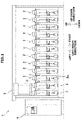
- FIG. 1 is a front view of the automatic winder 1 according to the present embodiment.
- the automatic winder 1 includes multiple winding units 2 (yarn winding devices of the present invention), a doffing device 3, and a main control device 4.
- the winding units 2 are arranged along the horizontal direction. Each of the winding units 2 performs a winding process in which the yarn Y pulled from a yarn feeder Bs is wound onto a winding bobbin Bw (see FIG. 2 ) to form a package P.
- a yarn supplying package or a yarn supplying bobbin is selected as the yarn feeder.
- the winding unit 2 for example, pulls the yarn Y from the yarn feeder Bs and winds the yarn Y onto the winding bobbin Bw to form a package P of a desired shape and a desired density.
- the doffing device 3 is arranged above the winding units 2, and is movable in the horizontal direction.
- the doffing device 3 Upon receiving a winding completion signal from a certain winding unit 2, the doffing device 3 travels to a position above the corresponding winding unit 2 to perform tasks such as removing the fully wound package P and mounting an empty winding bobbin Bw on the winding unit 2.
- the main control device 4 is arranged, for example, to the left side of the winding units 2.
- the main control device 4 is electrically connected to a unit controller 15 (explained later) of the winding unit 2 and a not-shown control section of the doffing device 3.
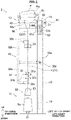
- FIG. 2 is a schematic front view of the winding unit 2.
- FIG. 3 is a schematic side view of the winding unit 2.
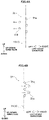
- FIGS. 4A and 4B are explanatory diagrams showing an operation of a tension applying device 31.
- the winding unit 2 includes a unit main body 10, a yarn supplying section 11, a yarn processing section 12, a winding section 13, an operation panel 14, and the unit controller 15 (control section of the present invention).
- the unit main body 10 is a columnar member that extends in the up-down direction.
- the yarn supplying section 11, the yarn processing section 12, and the winding section 13 are provided on a side surface of the unit main body 10.
- the yarn supplying section 11, the yarn processing section 12, and the winding section 13 are sequentially arranged in this order from the lower side to the upper side.
- the operation panel 14 is provided on the front surface of the upper end portion of the unit main body 10.
- the yarn supplying section 11 is for unwinding the yarn Y from the yarn feeder Bs and supplying the yarn Y to the subsequent unit.
- the yarn supplying section 11 includes a yarn feeder supporting section 21 and a yarn unwinding assisting device 22.
- the yarn feeder supporting section 21 supports the yarn feeder Bs substantially vertically.
- the yarn unwinding assisting device 22 regulates, with a regulating cylinder 23, the bulging that occurs when the yarn Y is unwound from the yarn feeder Bs.
- the regulating cylinder 23 can travel downward as the amount of the yarn wound on the yarn feeder Bs decreases so as to maintain a constant size of the bulge.
- a not-shown yarn feeler to detect the presence or absence of the running yarn is provided above the yarn unwinding assisting device 22.
- the yarn processing section 12 is configured to perform predetermined processing on the yarn Y.
- the yarn processing section 12 includes the tension applying device 31, a yarn guiding device 32, and a yarn speed sensor 33.
- the tension applying device 31 is configured to apply predetermined tension to the running yarn Y.
- the tension applying device 31 is arranged, for example, directly above the yarn supplying section 11.
- the yarn Y runs upwards along the up-down direction from the yarn supplying section 11 to the tension applying device 31.
- the up-down direction is equivalent to a first direction of the present invention.
- the tension applying device 31 is a so-called gate type device.
- the tension applying device 31 includes multiple fixed gate members 31a and multiple movable gate members 31b.
- the fixed gate members 31a and the movable gate members 31b are arranged alternately in the up-down direction.
- the fixed gate members 31a and the movable gate members 31b extend along the longitudinal direction and are cantilevered with the end portion as the base end.
- the movable gate members 31b can be switched between a tension applied state (shown by a solid line in FIG. 2 and FIG. 4B ; a resistance applied state of the present invention) and a tension released state (shown by a dashed line in FIG. 2 and FIG. 4A ).
- tension applied state shown by a solid line in FIG. 2 and FIG. 4B ; a resistance applied state of the present invention
- a tension released state shown by a dashed line in FIG. 2 and FIG. 4A
- tension applied onto the yarn Y As explained later, tension is applied onto the yarn Y.
- the movable gate members 31b are in the tension released state, the yarn Y can be guided through the fixed gate members 31a and the movable gate members 31b (explained in detail later).
- the movable gate members 31b are positioned to the right side of the fixed gate members 31a.
- the yarn Y mainly comes in contact with the left side of the fixed gate members 31a and the right side of the movable gate members 31b.
- the yarn Y is bent by the fixed gate members 31a and the movable gate members 31b.
- the fixed gate members 31a and the movable gate members 31b provide resistance due to a frictional force. Accordingly, tension is applied onto the yarn Y. The strength of the tension changes with the change in the position of the movable gate members 31b in the horizontal direction.
- the movable gate members 31b are positioned to the left side of the fixed gate members 31a. In this state, the yarn Y does not contact with at least the movable gate members 31b. In the tension released state, the yarn Y can be guided to the tension applying device 31 from the front side of the tension applying device 31. In the tension released state, no tension is applied to the yarn Y.
- the yarn guiding device 32 is arranged near the tension applying device 31. During the winding process, is the yarn Y positioned between the yarn supplying section 11 and the winding section 13 is disconnected due to some reason, the yarn guiding device 32 performs a part of a preparatory operation (explained in detail later) to join the yarn Y on the yarn supplying section 11 side in the yarn running direction (hereinafter, a first yarn Y1) and the yarn Y on the winding section 13 side (hereinafter, a second yarn Y2). For example, yarn breakage during the winding process can be cited as a reason for disconnection of the yarn Y.
- the operator joins the yarn end of the first yarn Y1 and the yarn end of the second yarn Y2.
- the operator joins the yarn end of the first yarn Y1 (shown by a double-dashed line in FIG. 3 ) and the yarn end of the second yarn Y2 (shown by a double-dashed line in FIG. 3 ) by using, for example, a portable yarn joining device 100 known in the art.
- the operator can manually tie the yarn end of the first yarn Y1 and the yarn end of the second yarn Y2.
- the working space S in which joining of the yarn end of the first yarn Y1 and yarn end of the second yarn Y2 can be performed is, for example, a space provided on the front side of the tension applying device 31.
- the space provided on the front side of the tension applying device 31 is the space on the working space S side in the longitudinal direction of the tension applying device 31.
- the longitudinal direction orthogonal to (intersecting) the up-down direction is equivalent to a second direction of the present invention.
- the yarn guiding device 32 includes a pipe-shaped arm 32b that is pivotable around a pivoting shaft 32a, a holding section 32c arranged at the tip end part of the arm 32b, and an arm driving motor 32d (the movement driving section of the present invention) that rotates and drives the arm 32b.
- the axial direction of the pivoting shaft 32a is nearly parallel to the horizontal direction.
- the pivoting shaft 32a is arranged, for example, above the tension applying device 31.
- the arm 32b is a pipe-shaped member that is bent in a substantially U shape.
- the arm 32b at least extends in a direction orthogonal to the horizontal direction (see FIG. 3 ).
- the arm 32b is arranged such that the movement range of the holding section 32c includes a position below the tension applying device 31 (shown by solid line in FIG. 2 and solid line in FIG. 3 ) and a position above the tension applying device 31 (shown by double-dashed line in FIG. 2 and double-dashed line in FIG. 3 ).
- the holding section 32c is movable between a position below the tension applying device 31 and a position above the tension applying device 31.
- the arm 32b is arranged so that the holding section 32c can be positioned in or near the working space S (see FIG. 3 ).
- the holding section 32c includes a suction port that is connected to a not-shown negative pressure source.
- the holding section 32c is configured to hold the first yarn Y1 by sucking and catching the first yarn Y1 with a negative pressure generated by the negative pressure source.
- the holding section 32c further includes, for example, a not-shown gripping member capable of holding the yarn end near the suction port, however the holding section 32c is not limited to such a configuration.
- the arm driving motor 32d is configured to move and drive the holding section 32c by swiveling and driving the arm 32b.
- the arm driving motor 32d is electrically connected to the unit controller 15 and is controlled by the unit controller 15.
- the yarn speed sensor 33 is a device that detects the speed (yarn speed) of the running yarn Y.
- the yarn speed sensor 33 outputs a predetermined signal to the unit controller 15 when, for example, the yarn Y is not detected due to yarn breakage caused by some reason.
- the winding section 13 is for forming the package P by winding the yarn Y on the winding bobbin Bw.
- the winding section 13 includes a cradle 41 (package supporting section of the present invention), a contact roller 42, a package driving motor 43 (package driving section of the present invention), and a traversing device 44.
- the cradle 41 rotatably supports the winding bobbin Bw (package P).
- the package driving motor 43 can rotate and drive the contact roller 42 in a direction in which the yarn Y is wound into the package P (forward direction) and a direction in which the yarn Y can be pulled from the package P (backward direction).
- the contact roller 42 is driven forwards to rotate the package P forwards, winding the yarn Y onto the package P.
- the contact roller 42 is driven backward to rotate the package P backwards (explained in detail later).
- the traversing device 44 traverses the yarn Y that runs towards the winding bobbin Bw.
- the traversing device 44 includes, for example, a not-shown arm, a traverse guide 44a attached to a tip end part of the arm, and a traverse motor 44b that swings and drives the arm in the horizontal direction.
- the traverse motor 44b drives the arm and also swings the arm, causing the traverse guide 44a to reciprocally move along the horizontal direction. Accordingly, the running yarn Y is traversed by the traverse guide 44a.
- the yarn Y is wound around the winding bobbin Bw while being traversed by the traversing device 44. Accordingly, the package P is formed.
- the operation panel 14 is operated by the operator. As shown in FIG. 2 , the operation panel 14 is arranged on a front surface of an upper end portion of the unit main body 10.
- the operation panel 14 includes operation buttons 51, a display panel 52 and a restart switch 53.
- the operation buttons 51 include, for example, an upward pointing triangular operation button 51a and a downward pointing triangular operation button 51b.
- the operation buttons 51a and 51b are, for example, turned on when the operator presses the button using a finger and turned off when the operator releases the finger.
- the display panel 52 is, for example, a liquid crystal display known in the art.
- the display panel 52 can include, for example, a not-shown LED lamp.
- the restart switch 53 is for restarting the winding process when the winding process is temporarily stopped.
- the operation panel 14 is electrically connected to the unit controller 15.
- the unit controller 15 is installed in the unit main body 10.
- the unit controller 15 includes a CPU, a ROM, and a RAM.
- the unit controller 15 controls various components of the winding unit 2 according to a computer program stored in the ROM by using the CPU.
- the unit controller 15 drives the package driving motor 43 while the package P is in contact with the contact roller 42 to rotate the contact roller 42.
- the yarn Y pulled from the yarn feeder Bs is wound onto the winding bobbin Bw to form the package P (winding process).
- the unit controller 15 executes control as explained below.
- FIG. 5 is a flowchart showing the control executed by the unit controller 15 on the tension applying device 31 and the yarn guiding device 32.
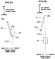
- FIGS. 6A to 6D are explanatory diagrams showing an operation of the yarn guiding device 32.
- the unit controller 15 controls each component of the winding unit 2 to execute the winding process.
- the tension applying device 31 is in the tension applied state (shown by a solid line in FIG. 2 and FIG. 4B ).
- the holding section 32c of the yarn guiding device 32 is positioned in a waiting position at which the holding section 32c does not interfere with the yarn Y.
- the unit controller 15 controls each component of the winding unit 2 to temporarily stop the winding process (Step S102).
- the unit controller 15 controls the arm driving motor 32d (see FIG. 2 ) of the yarn guiding device 32 to position the holding section 32c at the first position (see FIG.
- Step S103 the unit controller 15 controls the yarn guiding device 32 to suck and catch the first yarn Y1 using negative pressure.
- the operation of sucking and catching can be performed simultaneously with Step S103 or immediately after Step S103.
- Step S104 sets the state of the tension applying device 31 to the tension released state (Step S104, see FIG. 4A ). That is, the unit controller 15 sets the state of the tension applying device 31 to the tension released state before the holding section 32c that has caught the first yarn Y1 is moved to the second position (Step S105 explained later). Step S104 can be performed before or at the same time as Step S103.
- the unit controller 15 rotates the arm 32b by controlling the arm driving motor 32d, thereby moving the holding section 32c above the tension applying device 31 (Step S105, see FIG. 6B ).
- the position (second position) of the holding section 32c shown in FIG. 6B is a position opposing the first position with the tension applying device 31 interposed therebetween in the up-down direction. Accordingly, the first yarn Y1 is guided to the tension applying device 31. More specifically, the first yarn Y1 is arranged between the fixed gate members 31a and the movable gate members 31b in the horizontal direction (shown by a double-dashed line in FIG. 4A ).
- the unit controller 15 controls the tension applying device 31 to switch the movable gate members 31b from the tension released state to the tension applied state (Step S106, see FIG. 4B ).
- the unit controller 15 switches the state of the tension applying device 31 from the tension released state to the tension applied state before the holding section 32c that has caught the first yarn Y1 is moved from the second position (Step S107 explained later) .
- the first yarn Y1 is held by the fixed gate members 31a and the movable gate members 31b (in other words, the first yarn Y1 is introduced into the tension applying device 31).
- the fixed gate members 31a and the movable gate members 31b apply resistance to the first yarn Y1.
- Such a configuration prevents the first yarn Y1 from falling out of the tension applying device 31.
- the unit controller 15 rotates the arm 32b by controlling the arm driving motor 32d and stops the holding section 32c at a position (third position) while returning from the second position to the first position (Step S107, see FIG. 6C ).
- the third position is a position between the first position and the second position in the up-down direction.
- the third position is on the front side (working space S side) of the tension applying device 31 in the longitudinal direction and is also the position on the front side of both the first position and the second position. This makes it easier for the operator to manually pull the first yarn Y1 from the holding section 32c. It is preferable that the third position is above the tension applying device 31 in the up-down direction (the second position side in the up-down direction with respect to the tension applying device 31).
- various devices such as a not-shown device that supplies the yarn feeder Bs to the yarn feeder supporting section 21, are arranged near or below the tension applying device 31. Therefore, when the holding section 32c stops near the tension applying device 31 or below the tension applying device 31, the space for the operator to manually pull the first yarn Y1 may become narrower. On the other hand, a sufficient space for manually pulling the first yarn Y1 can be secured on the second position side in the up-down direction of the tension applying device 31.
- the unit controller 15 can return and stop the holding section 32c at the first position instead of stopping the holding section 32c at the third position (see FIG. 6D ). Even in this case, the first yarn Y1 is pulled out from the yarn feeder Bs and held by the tension applying device 31. In other words, some of the preparatory operations for joining the first yarn Y1 and the second yarn Y2 are performed by the yarn processing section 12. Therefore, it is possible to reduce the efforts of the operator to perform the preparatory operation.
- FIG. 7A is an explanatory diagram showing how the operation panel 14 is operated.
- FIG. 7B is an explanatory diagram showing how the second yarn Y2 is pulled out.
- the unit controller 15 When the operation button 51b is in the on state, the unit controller 15 reverses the rotation shaft of the package driving motor 43 at a predetermined rotation speed, drives the contact roller 42 in reverse, and rotates the package P in reverse. For example, as long as the operator continues to press the operation button 51b with his finger (see FIG. 7A ), the operation button 51b will remain on. Accordingly, the package driving motor 43 continues to run and the package P continues to rotate in reverse as long as the operator keeps pressing the operation button 51b with a finger. Therefore, the second yarn Y2 can be easily pulled out from the package P without requiring the second yarn Y2 to be pulled strongly (see FIG. 7B ).
- the unit controller 15 stops the package driving motor 43.
- the operation in which the operator presses the operation button 51b with his finger is the first operation to start the reverse operation of the package driving motor 43.
- the operation in which the operator releases his finger from the operation button 51b is the second operation for stopping the reverse operation of the package driving motor 43.
- the operator joins the first yarn Y1 and the second yarn Y2 by using the yarn joining device 100 (see FIG. 3 ). Finally, the operator presses the restart switch 53 (see FIG. 2 ). Accordingly, the stopped winding process is resumed.
- the holding section 32c by moving the holding section 32c from the first position to the second position, the first yarn Y1 can be introduced into the tension applying device 31. Accordingly, with such a configuration, the time and effort of the operator can be reduced compared to the case in which the operator introduces the first yarn Y1 into the tension applying device 31. Furthermore, the holding section 32c can be stopped at the first position or the third position so that the first yarn Y1 can be easily pulled from the holding section 32c. As explained above, the preparatory operation before joining the first yarn Y1 and the second yarn Y2 can be made easier in the winding unit 2 where the first yarn Y1 and the second yarn Y2 need to be joined by the operator.
- the unit controller 15 sets the state of the tension applying device 31 to the tension released state before the holding section 32c that has caught the first yarn Y1 is moved to the second position. Moreover, the unit controller 15 switches the state of the tension applying device 31 from the tension released state to the tension applied state before the holding section 32c that has caught the first yarn Y1 is moved from the second position. Accordingly, the first yarn Y1 can be reliably guided to the tension applying device 31. Moreover, it is possible to prevent the first yarn Y1 from falling off the tension applying device 31 after the first yarn Y1 is guided to the tension applying device 31.
- the unit controller 15 operates the package driving motor 43 to rotate the package P in a reverse direction when the operation panel 14 is operated in a state in which the yarn Y is disconnected into the first yarn Y1 and the second yarn Y2. In such a way, by operating the operation panel 14, the second yarn Y2 can be easily pulled while controlling the labor and / or damage done to the package P.
- the unit controller 15 continues to operate the package driving motor 43 from the time the operation button 51b is pressed until the operator releases his finger from the operation button 51b (that is, from the time the first operation is performed until the second operation is performed). With such a process, the second yarn Y2 of an arbitrary length can be pulled out depending on the operation performed by the operator.
- the unit controller 15 sets the state of the tension applying device 31 to the tension released state (Step S104) before the holding section 32c that has caught the first yarn Y1 is moved to the second position (Step S105); however, the unit controller 15 is not limited to such a configuration. Step S104 and Step S105 can be performed, for example, at the same time. Moreover, the unit controller 15 switches the state of the tension applying device 31 from the tension released state to the tension applied state (Step S106) before the holding section 32c that has caught the first yarn Y1 is moved from the second position (Step S107); however, the unit controller 15 is not limited to such a configuration. Step S106 and Step S107 can be performed, for example, at the same time.
- pressing the operation button 51b is the first operation
- releasing the finger from the operation button 51b is the second operation
- the present invention is not limited to such a configuration.
- the operation button 51b can be configured to switch between an on state and an off state each time the operation button 51b is pressed. That is, pressing the operation button 51b once when the operation button 51b is in the off state can be the first operation, and pressing the operation button 51b again when the operation button 51b is in the on state can be the second operation.
- the operation panel 14 includes the operation buttons 51a and 51b; however, the present invention is not limited to such a configuration. Instead of the operation buttons 51a and 51b, for example, a not-shown touchscreen can be provided.
- the unit controller 15 continues to operate the package driving motor 43 from the first operation until the second operation is performed on the operation panel 14; however, the present invention is not limited to such a configuration.
- the unit controller 15 can be set to operate the package driving motor 43 for a predetermined time period when the operation button 51b is pressed once (predetermined operation of the present invention). In such a way, each time the predetermined operation is performed, the second yarn Y2 that has a predetermined length can be pulled. Accordingly, by configuring an appropriate setting beforehand, the second yarn Y2 having an appropriate length can be pulled with a simple operation.
- the predetermined time period can be set beforehand, for example, in the main control device 4.
- information on the predetermined length for pulling the second yarn Y2 can also be stored in the main control device 4.
- information on the circumferential speed when the contact roller 42 rotates in the reverse direction is also stored in the main control device 4. Then, the predetermined time period can be calculated based on the information of the predetermined length and the information of the circumferential speed.
- the rotation shaft of the package driving motor 43 is reversely driven in order to rotate the package P in the reverse direction; however, the present invention is not limited to such a configuration.
- the package driving motor 43 can be used only for winding the yarn Y onto the winding bobbin Bw.
- a not-shown separating mechanism that separates the package P from the contact roller 42 when the yarn Y is disconnected, and a not-shown package driving section that drives the package P, which is separated from the contact roller 42, in the reverse direction can be provided.
- the package driving motor 43 can be provided in the cradle 41. In such a case, the winding bobbin Bw can be directly rotated by the package driving motor 43.
- the package P is reversely driven in order to pull the second yarn Y2 from the package P; however, the present invention is not limited to such a configuration. In other words, the operator may pull the second yarn Y2 from the package P while manually reversing the package P.
- the tension applying device 31 is switched to the tension released state (Step S104) before the first yarn Y1 is guided to the tension applying device 31 (Step S105) during the pulling control of the first yarn Y1; however, the present invention is not limited to such a configuration.
- Step S104 and Step 105 can be started at the same time.
- the winding unit 2 can be configured to guide the first yarn Y1 to the tension applying device 31 even when the tension applying device 31 is in the tension applied state. That is, for example, it is possible to provide on the front side of the tension applying device 31 a not-shown guide member configured to bend the first yarn Y1 that is moving backwards towards the tension applying device 31 in a wavelike shape.
- the winding unit 2 is provided with the gate type tension applying device 31; however, the present invention is not limited to such a configuration.
- the winding unit 2 can include a not-shown disc-type tension applying device that applies resistance to the yarn Y by positioning the yarn Y between a plurality of a not-shown disc.
- the present invention is not limited to the winding unit 2 of the automatic winder 1, and can be applied to various yarn winding devices that pull yarn from the yarn feeder to form a package.
- a yarn winding device is configured to form a package by winding a yarn that is pulled from a yarn feeder.
- the yarn winding device includes a tension applying device that applies tension to the yarn running towards the package side in a yarn running direction; a holding section that holds a first yarn when the yarn is disconnected into the first yarn on the yarn feeder side in the yarn running direction and a second yarn on the package side in the yarn running direction; a movement driving section that drives and moves the holding section between a first position where the first yarn can be caught and a second position where the first yarn can be introduced into the tension applying device; and a control section that controls the movement driving section to move the holding section from the first position to the second position while the first yarn is held in the holding section, and then return and stop the holding section at the first position, or stop the holding section at a third position on the way back to the first position.
- the holding section by moving the holding section from the first position to the second position, the first yarn can be introduced into the tension applying device. Accordingly, with such a configuration, the time and effort of the operator can be reduced compared to the case in which the operator introduces the first yarn into the tension applying device. Furthermore, the holding section can be stopped at the first position or the third position so that the first yarn can be easily pulled from the holding section. As explained above, the preparatory operation before joining the first yarn and the second yarn can be made easier in the yarn winding device where the first yarn and the second yarn need to be joined by the operator.
- control section controls, when the direction along the yarn running from the yarn feeder to the tension applying device is the first direction, the movement driving section to stop the holding section at the third position, which is a position that is more towards the working space, which is a space where the yarn end of the first yarn and the yarn end of the second yarn can be joined, than the first position and the second position.
- the control section controls, when the direction along the yarn running from the yarn feeder to the tension applying device is the first direction, the movement driving section to stop the holding section at the third position, which is a position that is more towards the working space, which is a space where the yarn end of the first yarn and the yarn end of the second yarn can be joined, than the first position and the second position.
- the yarn end of the first yarn and the yarn end of the second yarn are joined manually at the third position by an operator. Therefore, the yarn joining work can be performed at a position that is easy for the operator to handle.
- the tension applying device is switchable between a tension released state in which the first yarn held by the holding section can be introduced, and a resistance applied state in which resistance can be applied to the first yarn that is introduced by the holding section.
- the control section sets the state of the tension applying device to the tension released state before moving the holding section that holds the first yarn to the second position, and switches the state of the tension applying device from the tension released state to the resistance applied state before moving the holding section, which is holding the first yarn, from the second position.
- the resistance can be applied to the first yarn after the first yarn is guided to the tension applying device. Therefore, it is possible to prevent the first yarn from falling off the tension applying device.
- the above yarn winding device includes a package supporting section that rotatably supports the package; a package driving section capable of rotating the package in a direction opposite to the direction in which the yarn is wound; and an operation panel that can be operated by an operator.
- the control section operates the package driving section when the operation panel is operated when the yarn is disconnected into the first yarn and the second yarn.
- the second yarn When pulling out the second yarn from the package to join the first yarn and the second yarn, if the yarn is thin and / or the package is heavy (that is, the package is difficult to rotate as the inertial mass is large), pulling the yarn by the operator may cause the yarn to be broken off as the yarn may not be able to withstand the tensile stress. On the other hand, if the operator manually rotates the package in the reverse direction to prevent this from occurring, it takes time and effort, and may also damage the yarn on the surface of the package. In this regard, in the present invention, by operating the operation panel, the second yarn can be easily pulled while controlling the labor and / or damage done to the package.
- control section continues to operate the package driving section from when the first operation to start the operation of the package driving section is performed until the second operation to end the operation of the package driving section is performed.
- the second yarn of an arbitrary length can be pulled out depending on the operation by the operator.
- the control section operates the package driving section for a predetermined time period each time the predetermined operation to operate the package driving section is performed once.
- the second yarn that has a predetermined length can be pulled. Accordingly, by configuring an appropriate setting beforehand, the second yarn having an appropriate length can be pulled with a simple operation.
- a yarn joining method is used in a yarn winding device including a tension applying device that applies tension to a yarn running towards a package side in a yarn running direction; a holding section that holds a first yarn when the yarn is disconnected into the first yarn on a yarn feeder side in the yarn running direction and a second yarn on the package side in the yarn running direction; a movement driving section that drives and moves the holding section between a first position where the first yarn can be caught and a second position where the first yarn can be introduced into the tension applying device; and a control section.
- the yarn joining method includes a first step at which the control section controls the holding section to hold the first yarn; a second step at which the control section controls the movement driving section to move the holding section from the first position to the second position; and a third step at which the control section provides control to return the holding section to the first position and stop there, or, stop the holding section at a third position on the way back to the first position, so that joining of the yarn can be performed by an operator. Accordingly, the operator can perform the yarn joining efficiently.
Landscapes
- Engineering & Computer Science (AREA)
- Textile Engineering (AREA)
- Quality & Reliability (AREA)
- Replacing, Conveying, And Pick-Finding For Filamentary Materials (AREA)
- Tension Adjustment In Filamentary Materials (AREA)
- Spinning Or Twisting Of Yarns (AREA)
Applications Claiming Priority (1)
| Application Number | Priority Date | Filing Date | Title |
|---|---|---|---|
| JP2021007006A JP2022111528A (ja) | 2021-01-20 | 2021-01-20 | 糸巻取装置 |
Publications (2)
| Publication Number | Publication Date |
|---|---|
| EP4032844A1 true EP4032844A1 (de) | 2022-07-27 |
| EP4032844B1 EP4032844B1 (de) | 2023-12-27 |
Family
ID=78709279
Family Applications (1)
| Application Number | Title | Priority Date | Filing Date |
|---|---|---|---|
| EP21209227.4A Active EP4032844B1 (de) | 2021-01-20 | 2021-11-19 | Garnwicklungsvorrichtung |
Country Status (3)
| Country | Link |
|---|---|
| EP (1) | EP4032844B1 (de) |
| JP (1) | JP2022111528A (de) |
| CN (1) | CN114803688A (de) |
Citations (3)
| Publication number | Priority date | Publication date | Assignee | Title |
|---|---|---|---|---|
| EP2157039A2 (de) * | 2008-08-21 | 2010-02-24 | Murata Machinery, Ltd. | Textilmaschine |
| EP2594517A1 (de) * | 2010-07-15 | 2013-05-22 | Murata Machinery, Ltd. | Garnwicklungsvorrichtung |
| JP2016132574A (ja) | 2015-01-17 | 2016-07-25 | ザウラー ジャーマニー ゲゼルシャフト ミット ベシュレンクテル ハフツング ウント コンパニー コマンディートゲゼルシャフトSaurer Germany GmbH & Co. KG | 糸継ぎ部を評価する方法及び装置 |
Family Cites Families (5)
| Publication number | Priority date | Publication date | Assignee | Title |
|---|---|---|---|---|
| CH413677A (de) * | 1963-02-04 | 1966-05-15 | Volkmann & Co | Vorrichtung an Mehrfachdrahtzwirnmaschinen zum Festhalten des von der Vorlagespule ablaufenden Fadens bei Fadenbruch |
| DE10327370A1 (de) * | 2003-06-18 | 2005-01-13 | Rieter Ingolstadt Spinnereimaschinenbau Ag | Verfahren und Vorrichtung zum Anspinnen eines Fadens in einer Offenend-Spinnvorrichtung |
| JP2016188444A (ja) * | 2015-03-30 | 2016-11-04 | 村田機械株式会社 | クリーニング装置、ドラフト装置及び紡績機 |
| DE102015010844A1 (de) * | 2015-08-19 | 2017-02-23 | Saurer Germany Gmbh & Co. Kg | Verfahren zum Verbinden eines Ober- und eines Unterfadens an einer Spulstelle einer Spulmaschine und Spulstelle einer Spulmaschine |
| JP2019123590A (ja) * | 2018-01-16 | 2019-07-25 | 村田機械株式会社 | 糸巻取機 |
-
2021
- 2021-01-20 JP JP2021007006A patent/JP2022111528A/ja active Pending
- 2021-11-19 EP EP21209227.4A patent/EP4032844B1/de active Active
-
2022
- 2022-01-20 CN CN202210065569.0A patent/CN114803688A/zh active Pending
Patent Citations (3)
| Publication number | Priority date | Publication date | Assignee | Title |
|---|---|---|---|---|
| EP2157039A2 (de) * | 2008-08-21 | 2010-02-24 | Murata Machinery, Ltd. | Textilmaschine |
| EP2594517A1 (de) * | 2010-07-15 | 2013-05-22 | Murata Machinery, Ltd. | Garnwicklungsvorrichtung |
| JP2016132574A (ja) | 2015-01-17 | 2016-07-25 | ザウラー ジャーマニー ゲゼルシャフト ミット ベシュレンクテル ハフツング ウント コンパニー コマンディートゲゼルシャフトSaurer Germany GmbH & Co. KG | 糸継ぎ部を評価する方法及び装置 |
Also Published As
| Publication number | Publication date |
|---|---|
| CN114803688A (zh) | 2022-07-29 |
| EP4032844B1 (de) | 2023-12-27 |
| JP2022111528A (ja) | 2022-08-01 |
Similar Documents
| Publication | Publication Date | Title |
|---|---|---|
| EP2479129B1 (de) | Garnwicklungsmaschine | |
| EP2345611B1 (de) | Garnwickelmaschine und Garnführungsverfahren | |
| EP2511216B1 (de) | Garnwickelvorrichtung und Garnentnahmeverfahren | |
| CN111542481B (zh) | 纱线卷绕机 | |
| EP3072840A1 (de) | Garnwickelmaschine und garnwickelverfahren | |
| EP1457446B9 (de) | Vorrichtung zur Fadenspannungsregelung und zur Beseitigung von Fadenlockerungen in einer Garnwickeleinrichtung | |
| US5950957A (en) | Bobbin winding unit of a textile machine for producing cross-wound bobbins | |
| JP2013067469A (ja) | 糸巻取装置 | |
| EP2511215A2 (de) | Automatischer Wickler | |
| EP4032844B1 (de) | Garnwicklungsvorrichtung | |
| JP2007153554A (ja) | 糸巻取機 | |
| JP2013063838A (ja) | 糸巻取機 | |
| JP2016137959A (ja) | 糸巻取機 | |
| JP2012086925A (ja) | ボビンセット装置及びそれを備える糸巻取機 | |
| CN116803878A (zh) | 纱线卷取机以及纱线卷取方法 | |
| JP6861502B2 (ja) | 綾巻きパッケージを製造する繊維機械の作業ユニットにおいて糸走行を修正するための方法 | |
| CN112660914B (zh) | 纱线卷绕装置及纱线捕捉方法 | |
| CN113825714B (zh) | 线条体的卷绕装置及线条体的卷绕方法 | |
| JP2019064803A (ja) | 糸継装置、糸巻取装置、及び、糸継方法 | |
| JPH0680215B2 (ja) | 糸継ぎ方法 | |
| CN116969274A (zh) | 纱线卷取机 | |
| JP2025163715A (ja) | 自動ワインダ | |
| JP2004277947A (ja) | 糸継ぎ装置を備えた紡績機 | |
| CN121948222A (zh) | 纱线卷绕装置及纱线引导方法 | |
| JP2024168596A (ja) | 糸巻取機 |
Legal Events
| Date | Code | Title | Description |
|---|---|---|---|
| PUAI | Public reference made under article 153(3) epc to a published international application that has entered the european phase |
Free format text: ORIGINAL CODE: 0009012 |
|
| STAA | Information on the status of an ep patent application or granted ep patent |
Free format text: STATUS: THE APPLICATION HAS BEEN PUBLISHED |
|
| AK | Designated contracting states |
Kind code of ref document: A1 Designated state(s): AL AT BE BG CH CY CZ DE DK EE ES FI FR GB GR HR HU IE IS IT LI LT LU LV MC MK MT NL NO PL PT RO RS SE SI SK SM TR |
|
| STAA | Information on the status of an ep patent application or granted ep patent |
Free format text: STATUS: REQUEST FOR EXAMINATION WAS MADE |
|
| 17P | Request for examination filed |
Effective date: 20220819 |
|
| RBV | Designated contracting states (corrected) |
Designated state(s): AL AT BE BG CH CY CZ DE DK EE ES FI FR GB GR HR HU IE IS IT LI LT LU LV MC MK MT NL NO PL PT RO RS SE SI SK SM TR |
|
| GRAP | Despatch of communication of intention to grant a patent |
Free format text: ORIGINAL CODE: EPIDOSNIGR1 |
|
| STAA | Information on the status of an ep patent application or granted ep patent |
Free format text: STATUS: GRANT OF PATENT IS INTENDED |
|
| RIC1 | Information provided on ipc code assigned before grant |
Ipc: B65H 67/08 20060101AFI20230608BHEP |
|
| INTG | Intention to grant announced |
Effective date: 20230710 |
|
| GRAS | Grant fee paid |
Free format text: ORIGINAL CODE: EPIDOSNIGR3 |
|
| GRAA | (expected) grant |
Free format text: ORIGINAL CODE: 0009210 |
|
| STAA | Information on the status of an ep patent application or granted ep patent |
Free format text: STATUS: THE PATENT HAS BEEN GRANTED |
|
| AK | Designated contracting states |
Kind code of ref document: B1 Designated state(s): AL AT BE BG CH CY CZ DE DK EE ES FI FR GB GR HR HU IE IS IT LI LT LU LV MC MK MT NL NO PL PT RO RS SE SI SK SM TR |
|
| REG | Reference to a national code |
Ref country code: GB Ref legal event code: FG4D |
|
| REG | Reference to a national code |
Ref country code: CH Ref legal event code: EP |
|
| REG | Reference to a national code |
Ref country code: DE Ref legal event code: R096 Ref document number: 602021008082 Country of ref document: DE |
|
| REG | Reference to a national code |
Ref country code: IE Ref legal event code: FG4D |
|
| PG25 | Lapsed in a contracting state [announced via postgrant information from national office to epo] |
Ref country code: GR Free format text: LAPSE BECAUSE OF FAILURE TO SUBMIT A TRANSLATION OF THE DESCRIPTION OR TO PAY THE FEE WITHIN THE PRESCRIBED TIME-LIMIT Effective date: 20240328 |
|
| REG | Reference to a national code |
Ref country code: LT Ref legal event code: MG9D |
|
| PG25 | Lapsed in a contracting state [announced via postgrant information from national office to epo] |
Ref country code: LT Free format text: LAPSE BECAUSE OF FAILURE TO SUBMIT A TRANSLATION OF THE DESCRIPTION OR TO PAY THE FEE WITHIN THE PRESCRIBED TIME-LIMIT Effective date: 20231227 |
|
| PG25 | Lapsed in a contracting state [announced via postgrant information from national office to epo] |
Ref country code: ES Free format text: LAPSE BECAUSE OF FAILURE TO SUBMIT A TRANSLATION OF THE DESCRIPTION OR TO PAY THE FEE WITHIN THE PRESCRIBED TIME-LIMIT Effective date: 20231227 |
|
| PG25 | Lapsed in a contracting state [announced via postgrant information from national office to epo] |
Ref country code: LT Free format text: LAPSE BECAUSE OF FAILURE TO SUBMIT A TRANSLATION OF THE DESCRIPTION OR TO PAY THE FEE WITHIN THE PRESCRIBED TIME-LIMIT Effective date: 20231227 Ref country code: GR Free format text: LAPSE BECAUSE OF FAILURE TO SUBMIT A TRANSLATION OF THE DESCRIPTION OR TO PAY THE FEE WITHIN THE PRESCRIBED TIME-LIMIT Effective date: 20240328 Ref country code: FI Free format text: LAPSE BECAUSE OF FAILURE TO SUBMIT A TRANSLATION OF THE DESCRIPTION OR TO PAY THE FEE WITHIN THE PRESCRIBED TIME-LIMIT Effective date: 20231227 Ref country code: ES Free format text: LAPSE BECAUSE OF FAILURE TO SUBMIT A TRANSLATION OF THE DESCRIPTION OR TO PAY THE FEE WITHIN THE PRESCRIBED TIME-LIMIT Effective date: 20231227 Ref country code: BG Free format text: LAPSE BECAUSE OF FAILURE TO SUBMIT A TRANSLATION OF THE DESCRIPTION OR TO PAY THE FEE WITHIN THE PRESCRIBED TIME-LIMIT Effective date: 20240327 |
|
| REG | Reference to a national code |
Ref country code: NL Ref legal event code: MP Effective date: 20231227 |
|
| REG | Reference to a national code |
Ref country code: AT Ref legal event code: MK05 Ref document number: 1644353 Country of ref document: AT Kind code of ref document: T Effective date: 20231227 |
|
| PG25 | Lapsed in a contracting state [announced via postgrant information from national office to epo] |
Ref country code: NL Free format text: LAPSE BECAUSE OF FAILURE TO SUBMIT A TRANSLATION OF THE DESCRIPTION OR TO PAY THE FEE WITHIN THE PRESCRIBED TIME-LIMIT Effective date: 20231227 |
|
| PG25 | Lapsed in a contracting state [announced via postgrant information from national office to epo] |
Ref country code: SE Free format text: LAPSE BECAUSE OF FAILURE TO SUBMIT A TRANSLATION OF THE DESCRIPTION OR TO PAY THE FEE WITHIN THE PRESCRIBED TIME-LIMIT Effective date: 20231227 Ref country code: RS Free format text: LAPSE BECAUSE OF FAILURE TO SUBMIT A TRANSLATION OF THE DESCRIPTION OR TO PAY THE FEE WITHIN THE PRESCRIBED TIME-LIMIT Effective date: 20231227 Ref country code: NO Free format text: LAPSE BECAUSE OF FAILURE TO SUBMIT A TRANSLATION OF THE DESCRIPTION OR TO PAY THE FEE WITHIN THE PRESCRIBED TIME-LIMIT Effective date: 20240327 Ref country code: NL Free format text: LAPSE BECAUSE OF FAILURE TO SUBMIT A TRANSLATION OF THE DESCRIPTION OR TO PAY THE FEE WITHIN THE PRESCRIBED TIME-LIMIT Effective date: 20231227 Ref country code: LV Free format text: LAPSE BECAUSE OF FAILURE TO SUBMIT A TRANSLATION OF THE DESCRIPTION OR TO PAY THE FEE WITHIN THE PRESCRIBED TIME-LIMIT Effective date: 20231227 Ref country code: HR Free format text: LAPSE BECAUSE OF FAILURE TO SUBMIT A TRANSLATION OF THE DESCRIPTION OR TO PAY THE FEE WITHIN THE PRESCRIBED TIME-LIMIT Effective date: 20231227 |
|
| PG25 | Lapsed in a contracting state [announced via postgrant information from national office to epo] |
Ref country code: IS Free format text: LAPSE BECAUSE OF FAILURE TO SUBMIT A TRANSLATION OF THE DESCRIPTION OR TO PAY THE FEE WITHIN THE PRESCRIBED TIME-LIMIT Effective date: 20240427 |
|
| PG25 | Lapsed in a contracting state [announced via postgrant information from national office to epo] |
Ref country code: CZ Free format text: LAPSE BECAUSE OF FAILURE TO SUBMIT A TRANSLATION OF THE DESCRIPTION OR TO PAY THE FEE WITHIN THE PRESCRIBED TIME-LIMIT Effective date: 20231227 Ref country code: AT Free format text: LAPSE BECAUSE OF FAILURE TO SUBMIT A TRANSLATION OF THE DESCRIPTION OR TO PAY THE FEE WITHIN THE PRESCRIBED TIME-LIMIT Effective date: 20231227 |
|
| PG25 | Lapsed in a contracting state [announced via postgrant information from national office to epo] |
Ref country code: SK Free format text: LAPSE BECAUSE OF FAILURE TO SUBMIT A TRANSLATION OF THE DESCRIPTION OR TO PAY THE FEE WITHIN THE PRESCRIBED TIME-LIMIT Effective date: 20231227 |
|
| PG25 | Lapsed in a contracting state [announced via postgrant information from national office to epo] |
Ref country code: SM Free format text: LAPSE BECAUSE OF FAILURE TO SUBMIT A TRANSLATION OF THE DESCRIPTION OR TO PAY THE FEE WITHIN THE PRESCRIBED TIME-LIMIT Effective date: 20231227 Ref country code: SK Free format text: LAPSE BECAUSE OF FAILURE TO SUBMIT A TRANSLATION OF THE DESCRIPTION OR TO PAY THE FEE WITHIN THE PRESCRIBED TIME-LIMIT Effective date: 20231227 Ref country code: RO Free format text: LAPSE BECAUSE OF FAILURE TO SUBMIT A TRANSLATION OF THE DESCRIPTION OR TO PAY THE FEE WITHIN THE PRESCRIBED TIME-LIMIT Effective date: 20231227 Ref country code: IT Free format text: LAPSE BECAUSE OF FAILURE TO SUBMIT A TRANSLATION OF THE DESCRIPTION OR TO PAY THE FEE WITHIN THE PRESCRIBED TIME-LIMIT Effective date: 20231227 Ref country code: IS Free format text: LAPSE BECAUSE OF FAILURE TO SUBMIT A TRANSLATION OF THE DESCRIPTION OR TO PAY THE FEE WITHIN THE PRESCRIBED TIME-LIMIT Effective date: 20240427 Ref country code: EE Free format text: LAPSE BECAUSE OF FAILURE TO SUBMIT A TRANSLATION OF THE DESCRIPTION OR TO PAY THE FEE WITHIN THE PRESCRIBED TIME-LIMIT Effective date: 20231227 Ref country code: CZ Free format text: LAPSE BECAUSE OF FAILURE TO SUBMIT A TRANSLATION OF THE DESCRIPTION OR TO PAY THE FEE WITHIN THE PRESCRIBED TIME-LIMIT Effective date: 20231227 Ref country code: AT Free format text: LAPSE BECAUSE OF FAILURE TO SUBMIT A TRANSLATION OF THE DESCRIPTION OR TO PAY THE FEE WITHIN THE PRESCRIBED TIME-LIMIT Effective date: 20231227 |
|
| PG25 | Lapsed in a contracting state [announced via postgrant information from national office to epo] |
Ref country code: PL Free format text: LAPSE BECAUSE OF FAILURE TO SUBMIT A TRANSLATION OF THE DESCRIPTION OR TO PAY THE FEE WITHIN THE PRESCRIBED TIME-LIMIT Effective date: 20231227 Ref country code: PT Free format text: LAPSE BECAUSE OF FAILURE TO SUBMIT A TRANSLATION OF THE DESCRIPTION OR TO PAY THE FEE WITHIN THE PRESCRIBED TIME-LIMIT Effective date: 20240429 |
|
| PG25 | Lapsed in a contracting state [announced via postgrant information from national office to epo] |
Ref country code: PT Free format text: LAPSE BECAUSE OF FAILURE TO SUBMIT A TRANSLATION OF THE DESCRIPTION OR TO PAY THE FEE WITHIN THE PRESCRIBED TIME-LIMIT Effective date: 20240429 Ref country code: PL Free format text: LAPSE BECAUSE OF FAILURE TO SUBMIT A TRANSLATION OF THE DESCRIPTION OR TO PAY THE FEE WITHIN THE PRESCRIBED TIME-LIMIT Effective date: 20231227 |
|
| REG | Reference to a national code |
Ref country code: DE Ref legal event code: R097 Ref document number: 602021008082 Country of ref document: DE |
|
| PG25 | Lapsed in a contracting state [announced via postgrant information from national office to epo] |
Ref country code: DK Free format text: LAPSE BECAUSE OF FAILURE TO SUBMIT A TRANSLATION OF THE DESCRIPTION OR TO PAY THE FEE WITHIN THE PRESCRIBED TIME-LIMIT Effective date: 20231227 |
|
| PG25 | Lapsed in a contracting state [announced via postgrant information from national office to epo] |
Ref country code: DK Free format text: LAPSE BECAUSE OF FAILURE TO SUBMIT A TRANSLATION OF THE DESCRIPTION OR TO PAY THE FEE WITHIN THE PRESCRIBED TIME-LIMIT Effective date: 20231227 |
|
| PLBE | No opposition filed within time limit |
Free format text: ORIGINAL CODE: 0009261 |
|
| STAA | Information on the status of an ep patent application or granted ep patent |
Free format text: STATUS: NO OPPOSITION FILED WITHIN TIME LIMIT |
|
| 26N | No opposition filed |
Effective date: 20240930 |
|
| PG25 | Lapsed in a contracting state [announced via postgrant information from national office to epo] |
Ref country code: SI Free format text: LAPSE BECAUSE OF FAILURE TO SUBMIT A TRANSLATION OF THE DESCRIPTION OR TO PAY THE FEE WITHIN THE PRESCRIBED TIME-LIMIT Effective date: 20231227 |
|
| REG | Reference to a national code |
Ref country code: DE Ref legal event code: R119 Ref document number: 602021008082 Country of ref document: DE |
|
| REG | Reference to a national code |
Ref country code: CH Ref legal event code: PL |
|
| PG25 | Lapsed in a contracting state [announced via postgrant information from national office to epo] |
Ref country code: MC Free format text: LAPSE BECAUSE OF FAILURE TO SUBMIT A TRANSLATION OF THE DESCRIPTION OR TO PAY THE FEE WITHIN THE PRESCRIBED TIME-LIMIT Effective date: 20231227 |
|
| PG25 | Lapsed in a contracting state [announced via postgrant information from national office to epo] |
Ref country code: LU Free format text: LAPSE BECAUSE OF NON-PAYMENT OF DUE FEES Effective date: 20241119 |
|
| REG | Reference to a national code |
Ref country code: CH Ref legal event code: PL |
|
| PG25 | Lapsed in a contracting state [announced via postgrant information from national office to epo] |
Ref country code: CH Free format text: LAPSE BECAUSE OF NON-PAYMENT OF DUE FEES Effective date: 20241130 |
|
| REG | Reference to a national code |
Ref country code: BE Ref legal event code: MM Effective date: 20241130 |
|
| PG25 | Lapsed in a contracting state [announced via postgrant information from national office to epo] |
Ref country code: DE Free format text: LAPSE BECAUSE OF NON-PAYMENT OF DUE FEES Effective date: 20250603 |
|
| PG25 | Lapsed in a contracting state [announced via postgrant information from national office to epo] |
Ref country code: BE Free format text: LAPSE BECAUSE OF NON-PAYMENT OF DUE FEES Effective date: 20241130 |
|
| PG25 | Lapsed in a contracting state [announced via postgrant information from national office to epo] |
Ref country code: FR Free format text: LAPSE BECAUSE OF NON-PAYMENT OF DUE FEES Effective date: 20241130 |
|
| PG25 | Lapsed in a contracting state [announced via postgrant information from national office to epo] |
Ref country code: IE Free format text: LAPSE BECAUSE OF NON-PAYMENT OF DUE FEES Effective date: 20241119 |
|
| PG25 | Lapsed in a contracting state [announced via postgrant information from national office to epo] |
Ref country code: HU Free format text: LAPSE BECAUSE OF FAILURE TO SUBMIT A TRANSLATION OF THE DESCRIPTION OR TO PAY THE FEE WITHIN THE PRESCRIBED TIME-LIMIT; INVALID AB INITIO Effective date: 20211119 |
|
| PG25 | Lapsed in a contracting state [announced via postgrant information from national office to epo] |
Ref country code: CY Free format text: LAPSE BECAUSE OF FAILURE TO SUBMIT A TRANSLATION OF THE DESCRIPTION OR TO PAY THE FEE WITHIN THE PRESCRIBED TIME-LIMIT; INVALID AB INITIO Effective date: 20211119 |