EP4032813B1 - Computersichtsystem und -verfahren zur unterstützung der landeentscheidung - Google Patents
Computersichtsystem und -verfahren zur unterstützung der landeentscheidung Download PDFInfo
- Publication number
- EP4032813B1 EP4032813B1 EP22150135.6A EP22150135A EP4032813B1 EP 4032813 B1 EP4032813 B1 EP 4032813B1 EP 22150135 A EP22150135 A EP 22150135A EP 4032813 B1 EP4032813 B1 EP 4032813B1
- Authority
- EP
- European Patent Office
- Prior art keywords
- aircraft
- runway
- processor
- predefined
- data
- Prior art date
- Legal status (The legal status is an assumption and is not a legal conclusion. Google has not performed a legal analysis and makes no representation as to the accuracy of the status listed.)
- Active
Links
Images

Classifications
-
- B—PERFORMING OPERATIONS; TRANSPORTING
- B64—AIRCRAFT; AVIATION; COSMONAUTICS
- B64D—EQUIPMENT FOR FITTING IN OR TO AIRCRAFT; FLIGHT SUITS; PARACHUTES; ARRANGEMENT OR MOUNTING OF POWER PLANTS OR PROPULSION TRANSMISSIONS IN AIRCRAFT
- B64D43/00—Arrangements or adaptations of instruments
-
- G—PHYSICS
- G05—CONTROLLING; REGULATING
- G05D—SYSTEMS FOR CONTROLLING OR REGULATING NON-ELECTRIC VARIABLES
- G05D1/00—Control of position, course, altitude or attitude of land, water, air or space vehicles, e.g. using automatic pilots
- G05D1/04—Control of altitude or depth
- G05D1/06—Rate of change of altitude or depth
- G05D1/0607—Rate of change of altitude or depth specially adapted for aircraft
- G05D1/0653—Rate of change of altitude or depth specially adapted for aircraft during a phase of take-off or landing
- G05D1/0676—Rate of change of altitude or depth specially adapted for aircraft during a phase of take-off or landing specially adapted for landing
-
- B—PERFORMING OPERATIONS; TRANSPORTING
- B64—AIRCRAFT; AVIATION; COSMONAUTICS
- B64D—EQUIPMENT FOR FITTING IN OR TO AIRCRAFT; FLIGHT SUITS; PARACHUTES; ARRANGEMENT OR MOUNTING OF POWER PLANTS OR PROPULSION TRANSMISSIONS IN AIRCRAFT
- B64D45/00—Aircraft indicators or protectors not otherwise provided for
- B64D45/04—Landing aids; Safety measures to prevent collision with earth's surface
- B64D45/08—Landing aids; Safety measures to prevent collision with earth's surface optical
-
- B—PERFORMING OPERATIONS; TRANSPORTING
- B64—AIRCRAFT; AVIATION; COSMONAUTICS
- B64D—EQUIPMENT FOR FITTING IN OR TO AIRCRAFT; FLIGHT SUITS; PARACHUTES; ARRANGEMENT OR MOUNTING OF POWER PLANTS OR PROPULSION TRANSMISSIONS IN AIRCRAFT
- B64D47/00—Equipment not otherwise provided for
- B64D47/08—Arrangements of cameras
-
- B—PERFORMING OPERATIONS; TRANSPORTING
- B64—AIRCRAFT; AVIATION; COSMONAUTICS
- B64U—UNMANNED AERIAL VEHICLES [UAV]; EQUIPMENT THEREFOR
- B64U20/00—Constructional aspects of UAVs
- B64U20/80—Arrangement of on-board electronics, e.g. avionics systems or wiring
- B64U20/87—Mounting of imaging devices, e.g. mounting of gimbals
-
- B—PERFORMING OPERATIONS; TRANSPORTING
- B64—AIRCRAFT; AVIATION; COSMONAUTICS
- B64U—UNMANNED AERIAL VEHICLES [UAV]; EQUIPMENT THEREFOR
- B64U70/00—Launching, take-off or landing arrangements
- B64U70/90—Launching from or landing on platforms
- B64U70/95—Means for guiding the landing UAV towards the platform, e.g. lighting means
-
- G—PHYSICS
- G05—CONTROLLING; REGULATING
- G05D—SYSTEMS FOR CONTROLLING OR REGULATING NON-ELECTRIC VARIABLES
- G05D1/00—Control of position, course, altitude or attitude of land, water, air or space vehicles, e.g. using automatic pilots
- G05D1/10—Simultaneous control of position or course in three dimensions
- G05D1/101—Simultaneous control of position or course in three dimensions specially adapted for aircraft
- G05D1/106—Change initiated in response to external conditions, e.g. avoidance of elevated terrain or of no-fly zones
-
- G—PHYSICS
- G06—COMPUTING OR CALCULATING; COUNTING
- G06T—IMAGE DATA PROCESSING OR GENERATION, IN GENERAL
- G06T7/00—Image analysis
- G06T7/70—Determining position or orientation of objects or cameras
- G06T7/73—Determining position or orientation of objects or cameras using feature-based methods
-
- G—PHYSICS
- G06—COMPUTING OR CALCULATING; COUNTING
- G06V—IMAGE OR VIDEO RECOGNITION OR UNDERSTANDING
- G06V10/00—Arrangements for image or video recognition or understanding
- G06V10/20—Image preprocessing
- G06V10/22—Image preprocessing by selection of a specific region containing or referencing a pattern; Locating or processing of specific regions to guide the detection or recognition
-
- G—PHYSICS
- G06—COMPUTING OR CALCULATING; COUNTING
- G06V—IMAGE OR VIDEO RECOGNITION OR UNDERSTANDING
- G06V10/00—Arrangements for image or video recognition or understanding
- G06V10/20—Image preprocessing
- G06V10/25—Determination of region of interest [ROI] or a volume of interest [VOI]
-
- G—PHYSICS
- G06—COMPUTING OR CALCULATING; COUNTING
- G06V—IMAGE OR VIDEO RECOGNITION OR UNDERSTANDING
- G06V20/00—Scenes; Scene-specific elements
- G06V20/10—Terrestrial scenes
- G06V20/13—Satellite images
-
- G—PHYSICS
- G06—COMPUTING OR CALCULATING; COUNTING
- G06V—IMAGE OR VIDEO RECOGNITION OR UNDERSTANDING
- G06V20/00—Scenes; Scene-specific elements
- G06V20/50—Context or environment of the image
- G06V20/56—Context or environment of the image exterior to a vehicle by using sensors mounted on the vehicle
- G06V20/588—Recognition of the road, e.g. of lane markings; Recognition of the vehicle driving pattern in relation to the road
-
- G—PHYSICS
- G06—COMPUTING OR CALCULATING; COUNTING
- G06V—IMAGE OR VIDEO RECOGNITION OR UNDERSTANDING
- G06V20/00—Scenes; Scene-specific elements
- G06V20/60—Type of objects
- G06V20/64—Three-dimensional objects
-
- G—PHYSICS
- G06—COMPUTING OR CALCULATING; COUNTING
- G06V—IMAGE OR VIDEO RECOGNITION OR UNDERSTANDING
- G06V20/00—Scenes; Scene-specific elements
- G06V20/70—Labelling scene content, e.g. deriving syntactic or semantic representations
-
- H—ELECTRICITY
- H04—ELECTRIC COMMUNICATION TECHNIQUE
- H04L—TRANSMISSION OF DIGITAL INFORMATION, e.g. TELEGRAPHIC COMMUNICATION
- H04L67/00—Network arrangements or protocols for supporting network services or applications
- H04L67/01—Protocols
- H04L67/12—Protocols specially adapted for proprietary or special-purpose networking environments, e.g. medical networks, sensor networks, networks in vehicles or remote metering networks
-
- B—PERFORMING OPERATIONS; TRANSPORTING
- B64—AIRCRAFT; AVIATION; COSMONAUTICS
- B64D—EQUIPMENT FOR FITTING IN OR TO AIRCRAFT; FLIGHT SUITS; PARACHUTES; ARRANGEMENT OR MOUNTING OF POWER PLANTS OR PROPULSION TRANSMISSIONS IN AIRCRAFT
- B64D45/00—Aircraft indicators or protectors not otherwise provided for
- B64D2045/0075—Adaptations for use of electronic flight bags in aircraft; Supports therefor in the cockpit
-
- B—PERFORMING OPERATIONS; TRANSPORTING
- B64—AIRCRAFT; AVIATION; COSMONAUTICS
- B64U—UNMANNED AERIAL VEHICLES [UAV]; EQUIPMENT THEREFOR
- B64U10/00—Type of UAV
- B64U10/25—Fixed-wing aircraft
-
- G—PHYSICS
- G06—COMPUTING OR CALCULATING; COUNTING
- G06T—IMAGE DATA PROCESSING OR GENERATION, IN GENERAL
- G06T2207/00—Indexing scheme for image analysis or image enhancement
- G06T2207/10—Image acquisition modality
- G06T2207/10016—Video; Image sequence
-
- G—PHYSICS
- G06—COMPUTING OR CALCULATING; COUNTING
- G06T—IMAGE DATA PROCESSING OR GENERATION, IN GENERAL
- G06T2207/00—Indexing scheme for image analysis or image enhancement
- G06T2207/10—Image acquisition modality
- G06T2207/10032—Satellite or aerial image; Remote sensing
Definitions
- the present disclosure generally relates to systems and methods for providing assistance to deciding whether to go-around or continue a landing approach.
- Landing an aircraft is one of the most demanding maneuvers performed during flight.
- a pilot needs to make a decision of "continue approach” or "go-around” at a minimum decision height. This can be a challenging task and the pilot is required to make the decision within a short time period.
- the pilot In making the decision as to whether to continue the approach or to go-around, the pilot should be able to clearly see the landing environment for the approaching runway. The pilot should also check other conditions in order to continue landing, such as lateral and glideslope deviation, and must maintain with a range to complete the landing task.
- a go-around should be considered even if the pilot is able to make visual contact with the runway. Whilst pilots are trained to consider the various factors when deciding upon a go-around, it remains a matter of pilot judgement as to whether the aircraft is too high or too low, too left or too right for landing tasks with visual confirmation requirements. The effectiveness of a pilot in safely landing the aircraft depends on the experience and judgment of the pilot. Pilots with varying levels of experience and training may respond differently to the same situation, and some pilot responses may provide a less than optimal landing. Further, the decision to go-around or continue a landing approach places a cognitive burden on the pilot during an already strenuous flight sector.
- an object of the present disclosure is to provide a landing aid for an aircraft and associated methods using processing efficient software and existing hardware for many aircraft.
- the landing aid assists a pilot in deciding whether to go-around or continue an approach whilst ensuring compliance with a requirement for visual contact with the target runway.
- the landing aid may make the go-around or continue decision faster and better than many human pilots.
- the present disclosure provides computer vision systems and methods for an aircraft.
- the computer vision systems and methods identify a runway based on video frame data from a camera mounted to the aircraft, extract runway pixel positions associated with the runway, determine the aircraft position in a real world coordinate frame based on the pixel positions, receive predefined aircraft position data and go-around rules for a compliant approach to the runway, calculate an aircraft position deviation based on the aircraft position and the predefined aircraft position data, determine whether the aircraft position deviation is in conformance with the go-around rules, and output an indication of conformity with the go-around rules, receive reference aircraft position data from an aircraft sensor system; cross-check the aircraft position with the reference aircraft position data; and when the cross-check indicates a discrepancy beyond a threshold, outputting a warning and discontinuing determining whether the aircraft position deviation is in conformance with the go-around rules based on the video frame data.
- the reference aircraft position data is received from a global positioning system.
- Methods described herein include a camera mounted to an aircraft that outputs video frame data to a computer vision processor.
- the computer vision processor identifies a position of the runway in image space and determines a transformation function to the runway position in real world space based on data obtained from a navigation database.
- the transformation function can then be applied to the runway position in real world space to determine the camera position in real space, which can be used to determine the aircraft position.
- a continue approach or go-around decision is made. The decision is additionally based on predefined go-around rules and predefined aircraft position data that is determined based on the planned aircraft path to the target runway.
- the present disclosure provides systems and methods using a camera (e.g. a monocular camera) and a computer vision processor to compute aircraft a position (and optionally also speed) vector relative to a target runway in real-time.
- the systems and methods further compute aircraft position deviation from a current planned flight path, which provides predefined aircraft position data.
- the planned flight path is a predefined GS (Glide Scope) and LOC (Localizer) path.
- LOC Localizer Performance with Vertical guidance
- the systems and methods compare the calculated aircraft position from predefined aircraft position.
- the systems and methods announce an indication of conformity with go-around rules to the pilot, which can be a final decision as to whether to continue approach or to go-around.
- the systems and methods include a process for cross checking the determined aircraft position (e.g latitude, longitude and altitude) and optional speed vector (both horizontal and vertical) calculated by the computer vision processor against data coming out of aircraft sensors such as a global positioning system (GPS).
- GPS global positioning system
- the systems and methods described herein can provide a more accurate go-around decision in that computer/machine decision making based on computer vision processing and a predefined algorithm can be more accurate and consistent than a human decision based on pilot experiences.
- the integrity of the decision is assured as it relies on visual contact of the camera with the runway and may further include a cross-check feature. If the cross-check output is negative, the systems and methods will declare failure and not generate further guidance and annunciations.
- the computer vision algorithm can complete object detection (runway detection in this case) and other required calculations for positioning and decision making much faster than a human decision could usually be made.
- FIG. 1 depicts an exemplary embodiment of a computer vision system 10 associated with, or included within, an aircraft 12.
- This embodiment of the system 10 includes, without limitation, a camera 14, a navigation/airport database 16, a processing system 20, an output system 22, aircraft sensors 24, a computer vision processing module 26, a global positioning system (GPS) module 28, an aircraft position deviation module 40, go-around rules 18, a go-around decision module 30 and a cross-check module 42.
- GPS global positioning system
- FIG. 1 is a simplified representation of the computer vision system 10, and FIG. 1 is not intended to limit the application or scope of the subject matter in any way.
- the system 10 and/or the aircraft 12 will include numerous other devices and components for providing additional functions and features, as will be appreciated in the art.
- the aircraft 12 is a fixed wing aircraft or a rotorcraft or a UAV with remote piloting data link.
- the aircraft may be a passenger or cargo aircraft and can be any of various dimensions and weight capacities.
- the aircraft 12 has a camera 14 mounted thereon.
- the camera 14 is mounted to the wing of the aircraft 12, but embodiments are contemplated in which the camera 14 is mounted to the fuselage of the aircraft 12. Rather than being laterally displaced as in the exemplary embodiment, the camera 14 may be located along a central longitudinal axis of the aircraft 12.
- the camera 14 is a monocular digital camera, although other types of camera 14 are contemplated. Other vision cameras are possible including stereo cameras, infrared cameras, etc..
- the camera 14 can include a plurality of cameras including combinations of different types of cameras such as those described above.
- the images are generated via single camera or real-time fusion of multiple cameras.
- the resolution of the camera may be no less than WUXGA resolution (1920x1080 pixels) or application dependent for pixel feature extractions
- the camera 14 is mounted on the front of aircraft 12 so as to provide a front view of a scene ahead of the aircraft 12 that will encompass a target runway at a decision height for the aircraft 12.
- the camera 14 may be mounted on a center of the front of a nose of the aircraft or may be laterally offset.
- the camera 14 has a 50mm lens, which translates to a field of view of 39.6 (deg) and 27.0 (deg) on X and Y axis, respectively, for an FX formatted image sensor (36 x 24mm).
- the camera 14 is mounted with a certain range of pitch angle measured with respect to the aircraft body longitudinal axis. Given the aircraft gliding path is often 3 degrees, a normal pitch angle of -2 degrees of the aircraft during approach, a vertical FOV of the 50mm lens is 27 degrees and the camera mounting pitch angle should be 6 or 7 degrees.
- the camera 14 produces video frame data 50 that can include a target runway.
- the format of the video frame data 50 could be 8 bits depth grayscale data with a resolution of 1920x1080. However, greater sensitivity (bits) or color data could also be provided by the camera 14.
- the video frame data 50 is provided to the computer vision processing module 26 for processing to identify the target runway and from that to determine a real world position of the aircraft 12.
- the computer vision system 10 includes a navigation database 16 that stores navigation data used by various avionics systems.
- the navigation database 16 provides data 52 for the real world position of a target runway.
- the target runway may be established by a flight plan from a flight management system (FMS) or selected by a pilot or derived based on a location of the aircraft 12 from the GPS module 28.
- the navigation database 16 can be interrogated to determine data points representing the target runway in a real world coordinate frame.
- the navigation database 16 may, alternatively, be a dedicated airport runway database.
- the navigation database 16 may be stored digitally in an airborne avionics computer. For example, many modern aircraft 12 have an FMS and a navigation database that contains runway location data.
- the navigation database may be updated regularly through wired or wireless data connections.
- the data 52 provided by the navigation database 16 may include a runway centerline, a length of the runway, a width of the runway, coordinates for corner points of the runway, coordinates for a center point of the runway and other data describing dimensions and location of the runway.
- the coordinates may be relative to the runway or in a global coordinate frame, both of which are in a real world coordinate frame rather than an image space coordinate frame.
- the data 52 can be combined with corresponding data in image space extracted by the computer vision processing module 26 in order to determine a translation matrix that is used in subsequent processing to derive the aircraft position in the real world coordinate frame.
- the computer vision system 10 includes the aircraft sensors 24 and the GPS module 28.
- the aircraft sensors 24 include at least an inertial measurement unit (IMU).
- the GPS module 28 may include a Global Positioning System (GPS) or global navigation satellite system (GNSS) receiver.
- GPS Global Positioning System
- GNSS global navigation satellite system
- the IMU includes one or more gyroscopes and accelerometers.
- the aircraft sensors 24 and the GPS module 28 individually or in combination determines location (and optionally also orientation information) for the aircraft 12.
- the GPS module 28 determines location data based on global position data obtained from satellites, e.g. by trilateration with three or more satellites and based on inertial measurements.
- the GPS module 28 determines location of the aircraft 12 based on Wide Area Augmentation System (WAAS) or other augmented satellite-based global position data.
- WAAS Wide Area Augmentation System
- a network of ground-based reference stations provides measurements of small variations in the GPS satellites' signals so that onboard GPS or GNSS receivers use the corrections while computing their positions to improve accuracy of location measurements.
- the IMU of the aircraft sensors 24 may additionally or alternatively allow the global position and orientation of the aircraft to be derived.
- the aircraft sensors 24 and/or the GPS module 28 outputs reference aircraft position data 55, which can be used in a cross-check process to determine whether the real world aircraft position 54 determined by the computer vision processing module 26 is reasonable.
- the aural annunciator 46 and the display device 48 are located in a cockpit of the aircraft 12.
- the display device 48 includes a head down display (HDD), a head up display (HUD), a wearable HUD, a portable display or any combination thereof.
- the display device 48 may be dashboard/cockpit integrated display or an Electronic Flight Bag (EFB) device.
- the aural annunciator may include a cockpit integrated speaker or may be included in a headset of the pilot.
- System 10 further includes the processing system 20 including one or more processors that are configured to execute computer programming instructions stored on non-transitory memory (not shown). Functions of the computer vision system 10 and steps of the method 200 ( FIG. 2 ) are executed by one or more processors of the processing system 20 and the associated computer programming instructions.
- Modules, sub-modules and the processing system 20 as described herein refer to any hardware, software, firmware, electronic control component, processing logic, and/or processor device, individually or in any combination, including without limitation: application specific integrated circuit (ASIC), an electronic circuit, a processor (shared, dedicated, or group) and memory that executes one or more software or firmware programs, a combinational logic circuit, and/or other suitable components that provide the described functionality.
- ASIC application specific integrated circuit
- the computer vision processing module 26 includes a runway identification sub-module 32, a translation matrix calculation sub-module 34, an aircraft position calculation sub-module and a computer vision processor 38.
- the computer vision processor 38 may be a dedicated processor adapted for image processing operations or the computer vision processor 38 may be a general purpose processor included in the processing system 20.
- the computer vision processor 38 executes programming instructions that cause the at least one processor to execute the functions and steps of the computer vision processing module 26 as described herein.
- the runway identification sub-module 32 processes the video frame data 50 and executes an object finding function or algorithm tuned to identify a runway in the video frame data 50.
- an object finding function or algorithm tuned to identify a runway in the video frame data 50.
- Numerous runway detection algorithms could be constructed.
- a machine learning classifier is used that is trained with images including a runway.
- One example classifier is the Cascade Classifier.
- a classical image processing approach could also be used, which does not rely on machine learning algorithms.
- feature or pattern matching algorithms could be used to identify the runway.
- the object finding function returns a positive or negative indication concerning whether a runway has been found and returns a region of interest (ROI) outline (e.g. a rectangle) encompassing the identified runway.
- the ROI may be a little larger and contain the convex hull of the runway.
- the runway identification sub-module 32 further processes, e.g. by contrast filtering and/or edge detection, the ROI to determine runway pixel positions (or other location data in image space) 56 describing the location of the runway in image space. In one embodiment, three or four corner points of the runway in image or pixel coordinates are output by the runway identification sub-module 32.
- the translation matrix calculation sub-module 34 receives the pixel positions 56 in two dimensional image coordinates (e.g. x and y). The translation matrix calculation sub-module 34 determines a translation matrix 58 for transforming the position the position of the runway in real world coordinates to a position of the camera 14 in real world coordinates.
- the translation matrix 58 is determined based on intrinsic parameters of the camera 14, the pixel positions 56 and the data 52 for real world position of the runway.
- the translation matrix 58 represents a transformation from camera coordinates to real world coordinates. If the translation matrix 58 is known, it is possible to determine the position of the camera (and thus the real world aircraft position 54) from the data 52.
- W (R, t), wherein R is a rotation matrix (e.g. a 3 by 1 rotation matrix in Rodrigues transform format) and t is the translation matrix 58.
- Q is the data 52 for real world position of the runway as a three dimensional space vector (X, Y, Z) in the form of a 3 by 1 matrix.
- the data 52 can be in the global coordinates, in local airport coordinates or in coordinates relative to the runway.
- the data 52 may be three or four corners of the runway in some embodiments but other trackable features of the runway may be used provided the location of corresponding features can be extracted by the computer vision processing module 26.
- q are the pixel positions 56 as a 2 by 1 matrix representing the computer vision determined points of the runway in camera body coordinates.
- translation matrix calculation sub-module 34 Given M (3x3 Camera intrinsic Matrix), q (2x1 pixel positions 56 on the camera 14), Q (3x1 runway position of the pixel in runway/real world coordinates) and R (rotation matrix of the camera 14), the t matrix is solved based on intrinsic camera parameters, the pixel positions 56 for the runway determined by computer vision processing of the video frame data 50 and the known position of the runway based on the data 52 for the real world position of the runway.
- the runway threshold position is taken for the position of the runway and the length of the runway is retrieved from the navigation database 16.
- Q Runway length 2 0 0
- R 0.13962634 0 0
- Equation 3 can thus be solved based on the pixel positions 56 coming from the runway identification sub-module 32 to derive t.
- the pixel positions correspond to the runway threshold point in the camera image in x, y form.
- the R matrix is also unknown such that additional runway points are required to solve both R and t.
- at least 3 non-relative points are included in the pixel positions.
- three or four corner points for the runway are used to solve for R and t based on corresponding corner points for the runway included in the data 52 taken from the navigation database 16.
- the translation matrix 58 is received by the aircraft position calculation sub-module 36 and processed to derive a position of the camera 14 and, based thereon, the real world aircraft position 54.
- the aircraft position calculation sub-module 36 may also determine a speed vector 60 for the aircraft based on a time derivative of the real world aircraft position 54.
- the speed vector 60 can be used as an additional variable for the cross-checking process described in the following.
- the computer vision system 10 includes an aircraft position deviation module 40 that received a planned flight path 62 and the real world aircraft position 54.
- the planned flight path 62 can be obtained from ILS data or from an FMS.
- the planned flight path 62 includes a desired glide slope and a desired position laterally with respect to the target runway.
- the planned flight path 62 thus provides predefined aircraft position data.
- the aircraft position deviation module 40 compares the real world aircraft position 54 and the planned flight path 62 and determines a deviation therebetween in the form of an aircraft position deviation 64. More specifically, the aircraft position deviation module 40 determines an aircraft position deviation with respect to the Glide Slope (GS) and the Localizer (LOC) in the planned flight path 62.
- Z POS is the Z value in the matrix of the real world aircraft position 54.
- X POS is the X value in the matrix of real world aircraft position 54 and X LOC is taken from the planned flight path 62.
- the go-around decision module 30 may cease operation at a fixed or variably calculated height.
- the MDA varies depending on the category of the aircraft 12 and some other factors and is available in reference information accessible by the FMS. For CAT 1 aircraft, the MDA is greater than or equal to 200 feet (60m). For CAT II aircraft, the MDA is greater than or equal to 100 feet. For CAT III aircraft, the MDA may be less than 100 feet or there may be no MDA.
- the go-around rules 18 may be defined by an aviation authority, by the aircraft carrier or by a system provider. The go-around rules 18 define maximum deviations from the planned flight path 62. The go-around decision module 18 compares the go-around rules 18 with the aircraft position deviation 64 to determine conformance with the rules.
- a decision 66 is output to go-around.
- a decision 66 is output to continue the approach (or there is an absence of a decision 66 to go-around).
- the go-around rules 18 are stored on memory of the computer vision system 10.
- the go-around rules are taken from the International Civil Aviation Organization (ICAO) Standards and Recommended Practices (SARPs) and are as follows: Table 1 Go-around Threshold (>meter) CAT I CAT II/CAT III D GS 10 5.3 D LOC 40 17
- the computer vision system 10 includes a cross-check module 42 for verifying whether the real world aircraft position 54 is sufficiently reasonable by comparing it with corresponding reference aircraft position data 55 from the aircraft sensors 24 and/or from the GPS module 28.
- the speed vector 60 from the computer vision processing module 26 is compared to reference speed data from the aircraft sensors 24 and/or the GPS module 28 as an additional cross-check parameter.
- the cross-check module 42 determines whether the real world aircraft position 54 and optionally also the speed vector 60 are sufficiently close to the reference data based on thresholds. When the thresholds are breached, the real world aircraft position 54 is considered unreliable.
- the go-around decision module 30 ceases to operate and the pilot is warned that the automatic go-around decision process is no longer operational.
- the warning is provided through aural and/or visual indication by the output system 22.
- Example thresholds for the difference between the real word aircraft position and speed data 54, 60 and the reference data 55 are provided in table 2 below.
- Threshold CATI Threshold CAT II/CAT III X m 20 15 Y m 20 15 Z m 5 2 V ns m/s 10 10 V ew m/s 10 10 V up m/s 2.5 1
- the computer vision system 10 is described herein as being located in the aircraft 12, it should be understood that remote or cloud processing capabilities and data sources could be used by the aircraft 12 to implement at least some parts of the computer vision system 10. As such, one or more components described with respect to the aircraft 12 may not necessarily be located onboard the aircraft 12.
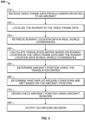
- FIG. 2 is a flowchart illustrating an exemplary method 200 for providing a go-around or continue approach decision 66.
- the decision 66 is based on computer vision processing of video frame data 50 to identify the runway and the location of the runway in camera coordinates. Based on a relation between the location of the identified runway in camera coordinates and the real world position of the runway 52, the real word aircraft position 54 can be derived from the computer vision processing. The aircraft position deviation 64 can then be determined to allow a go-around decision to be output when the deviation is too great. Steps of method 200 are performed by the computer vision system 10 of FIG. 1 (FIG. 1 ).
- Method 200 commences, in some embodiments, when the aircraft 12 is determined to be within a predetermined proximity of the target runway based on a location of the aircraft 12 from the global positioning system module 28 and/or from the aircraft sensors 24.
- method 200 is invoked when the altitude of the aircraft 12 is less than a predetermined altitude during a landing approach. For example, when the aircraft altitude is less than 1000 feet.
- the aircraft altitude may be determined based on altitude data from a radio altimeter included in the aircraft sensors 24.
- the method 200 may repeat so as to continuously process each frame (or every n frames) of incoming video frame data 50.
- the method 200 may cease when the altitude of the aircraft 12 is less than a set threshold such as less than 50 feet.
- the method may also cease when the cross-check process indicates insufficiently reliable data is being determined by the computer vision processing module 26.
- step 210 the video frame data 50 is received from the camera 14.
- step 220 the video frame data 50 is processed by the computer vision processing module 26 to localize the runway.
- Step 220 may include execution of an object finding algorithm that is tuned to identify and localize runways.
- Step 220 produces pixel positions for the identified runway, which may include one, two, three or more discrete locations on the runway.
- step 230 data 52 for the real world position of the runway is retrieved from the navigation database 16.
- the computer vision system 10 derives a target runway based on a flight plan or based on aircraft position and heading information from the GPS module 28 and/or the aircraft sensors 24 and information on the most likely runway at a nearby airport.
- the most likely runway can be derived from factors such as proximity and alignment, which are available from the navigation database 16.
- step 240 the translation matrix 58 is calculated based on intrinsic parameters of the camera 14, the pixel positions 56 representing the runway location in camera coordinates and the data 52 representing the position of the runway in real world coordinates from the navigation database 16.
- step 250 the real world aircraft position 54 in world coordinates is determined based on the translation matrix 58 and the data 52 representing the position of the runway in real world coordinates.
- step 260 an automated decision is made as to whether go-around conditions are met based on the real world aircraft position 54 and whether a deviation between the real world aircraft position 54 and the planned flight path 62 exceed thresholds specified by go-around rules.
- step 280 the go-around decision 66 (which may be a continue approach or go-around state) is output to the pilot via the output system 22 in aural and/or visual form. The pilot can then take go-around or continue approach action based on the output from step 260.
- the method includes step 270 in which a cross-check is carried out on the real world aircraft position 54 as compared to reference aircraft position data 55 from the aircraft sensors 24 and/or from the GPS module 28.
- a cross-check on the speed vector 60 may also be implemented. If the cross-check indicates that the data determined by the computer vision processing module 26 is insufficiently reliable, then method 200 may cease and the pilot makes the go-around decision without additional support from the computer vision system 10.
- the computer vision system 10 could be used only to indicate to a pilot, through the output system 22, that visual contact has been made with the runway by processing the video frame data 50. In another embodiment, this indication could be combined with later indications concerning the go-around/continue approach decision.
- Embodiments of the computer vision system 10 have been described in terms of functional and/or logical block components and various processing steps. It should be appreciated that such block components may be realized by any number of hardware, software, and/or firmware components configured to perform the specified functions. For example, an embodiment of the present disclosure may employ various integrated circuit components, e.g., memory elements, digital signal processing elements, logic elements, look-up tables, or the like, which may carry out a variety of functions under the control of one or more microprocessors or other control devices. In addition, those skilled in the art will appreciate that embodiments of the present disclosure may be practiced in conjunction with any number of systems, and that the systems described herein is merely exemplary embodiments of the present disclosure.
Landscapes
- Engineering & Computer Science (AREA)
- Aviation & Aerospace Engineering (AREA)
- General Physics & Mathematics (AREA)
- Physics & Mathematics (AREA)
- Theoretical Computer Science (AREA)
- Remote Sensing (AREA)
- Multimedia (AREA)
- Automation & Control Theory (AREA)
- Radar, Positioning & Navigation (AREA)
- Microelectronics & Electronic Packaging (AREA)
- Mechanical Engineering (AREA)
- Medical Informatics (AREA)
- Computer Networks & Wireless Communication (AREA)
- Signal Processing (AREA)
- Computer Vision & Pattern Recognition (AREA)
- General Health & Medical Sciences (AREA)
- Computing Systems (AREA)
- Health & Medical Sciences (AREA)
- Astronomy & Astrophysics (AREA)
- Computational Linguistics (AREA)
- Traffic Control Systems (AREA)
Claims (10)
- Computer-Vision-System (10) für ein Flugzeug (12), umfassend:eine Kamera (14), die an dem Flugzeug angebracht und dazu konfiguriert ist, Videorahmendaten (50) einer Szene, die dem Flugzeug vorausliegt, auszugeben;einen Prozessor (20), der in betriebsfähiger Kommunikation mit der Kamera ist, wobei der Prozessor dazu konfiguriert ist, Programmanweisungen auszuführen, wobei die Programmanweisungen dazu konfiguriert sind, den Prozessor zu veranlassen, die Videorahmendaten dazu zu verarbeiten:eine Anzeige der Übereinstimmung mit den Warteschleife-Regeln auszugeben, gekennzeichnet dadurch, dass die Programmanweisungen ferner dazu konfiguriert sind, den mindestens einen Prozessor, dazu zu veranlassen:eine Landebahn zu identifizieren;Landebahnpixelpositionen (56) zu extrahieren, die der Landebahn zugehörig sind;die Flugzeugposition in einem realen Koordinatenrahmen auf Basis der Pixelpositionen zu bestimmen;vordefinierte Flugzeugpositionsdaten und Warteschleife-Regeln (18) für einen konformen Anflug auf die Landebahn zu empfangen;eine Flugzeugpositionsabweichung (64) auf Basis der Flugzeugposition und der vordefinierten Flugzeugpositionsdaten zu berechnen;zu bestimmen, ob die Flugzeugpositionsabweichung in Übereinstimmung mit den Warteschleife-Regeln ist; undReferenzflugzeugpositionsdaten (55) aus einem globalen Positionierungssystem des Flugzeugs zu empfangen;die Flugzeugposition mit den Referenzflugzeugpositionsdaten abzugleichen; undwenn der Abgleich eine Diskrepanz oberhalb eines Schwellenwerts angibt, eine Warnung auszugeben und das Bestimmen, ob die Flugzeugpositionsabweichung in Übereinstimmung mit den Warteschleifen-Regeln ist, auf Basis der Videorahmendaten abzubrechen.
- Computer-Vision-System nach Anspruch 1, wobei die Programmanweisungen dazu konfiguriert sind, den mindestens einen Prozessor zu veranlassen:
die Flugzeugposition in dem realen Koordinatenrahmen auf Basis der Pixelpositionen durch Folgendes zu bestimmen:Abrufen von Ortsdaten für eine Landebahn in dem realen Koordinatenrahmen von einer Flughafendatenbank (16);Berechnen einer Translationsmatrix (58) auf Basis der Landebahnpixelpositionen und der Ortsdaten; undBestimmen der Flugzeugposition in dem realen Koordinatenrahmen auf Basis der Translationsmatrix. - Computer-Vision-System nach Anspruch 1, wobei:die vordefinierten Flugzeugpositionsdaten einen vordefinierten Gleitpfad beinhalten;die Flugzeugposition eine Flugzeughöhe und eine Längsposition des Flugzeugs beinhaltet, wobei die Programmanweisungen dazu konfiguriert sind:eine vordefinierte Flugzeughöhe auf Basis des vordefinierten Gleitpfades und der Längsposition des Flugzeugs zu bestimmen;eine Gleitpfadabweichung auf Basis der vordefinierten Flugzeughöhe und der Flugzeughöhe zu berechnen; undzu bestimmen, ob die Gleitpfadabweichung in Übereinstimmung mit den Warteschleife-Regeln ist.
- Computer-Vision-System nach Anspruch 1, wobei:die Flugzeugposition eine seitliche Position des Flugzeugs beinhaltet;die vordefinierten Flugzeugpositionsdaten eine vordefinierte seitliche Position beinhalten, wobei die Programmanweisungen dazu konfiguriert sind:eine seitliche Positionsabweichung auf Basis der vordefinierten seitlichen Position und der seitlichen Position des Flugzeugs zu berechnen; undzu bestimmen, ob die seitliche Positionsabweichung in Übereinstimmung mit den Warteschleife-Regeln ist.
- Computer-Vision-System nach Anspruch 1, wobei die Landebahnpixelpositionen mindestens drei Landebahnpixelpositionen umfassen.
- Verfahren zum Unterstützen einer Landeentscheidung für ein Flugzeug (12), das Verfahren umfassend:Empfangen, über mindestens einen Prozessor (20), von Videorahmendaten (50) von einer Kamera (14), die an dem Flugzeug angebracht ist;Identifizieren, über den mindestens einen Prozessor, einer Landebahn auf Basis der Videorahmendaten und durch Verwenden eines Objekterkennungsalgorithmus;Extrahieren, über den mindestens einen Prozessor, von Landebahnpixelpositionen (56), die der identifizierten Landebahn zugehörig sind;Bestimmen, über den mindestens einen Prozessor, der Flugzeugposition in einem realen Koordinatenrahmen auf Basis der Pixelpositionen, der intrinsischen Kameraparameter und einer realen Position der Landebahn, die aus einer Navigationsdatenbank (16) abgerufen wird;Empfangen, über den mindestens einen Prozessor, von vordefinierten Flugzeugpositionsdaten und Warteschleife-Regeln (18) für einen konformen Anflug auf die Landebahn;Berechnen, über den mindestens einen Prozessor, einer Flugzeugpositionsabweichung (64) auf Basis der bestimmten Flugzeugposition und der vordefinierten Flugzeugpositionsdaten;Bestimmen, über den mindestens einen Prozessor, ob die Flugzeugpositionsabweichung in Übereinstimmung mit den Warteschleife-Regeln ist; undAusgeben, über den mindestens einen Prozessor, einer Anzeige der Übereinstimmung mit den Warteschleife-Regeln, und gekennzeichnet durch ferner umfassend:Empfangen, über den mindestens einen Prozessor, von Referenzflugzeugpositionsdaten (55) von einem globalen Positionierungssystem des Flugzeugs;Abgleichen, über den mindestens einen Prozessor, der Flugzeugposition mit den Referenzflugzeugpositionsdaten; undwenn der Abgleich eine Diskrepanz über einem Schwellenwert angibt, Ausgeben, über den mindestens einen Prozessor, einer Warnung und Abbrechen des Bestimmens, ob die Flugzeugpositionsabweichung in Übereinstimmung mit den Warteschleifen-Regeln ist, auf Basis der Videorahmendaten.
- Verfahren nach Anspruch 6, umfassend:
Bestimmen, über den mindestens einen Prozessor, der Flugzeugposition in dem realen Koordinatenrahmen auf Basis der Pixelpositionen durch:Berechnen einer Translationsmatrix (58) auf Basis der Landebahnpixelpositionen und der realen Position der Landebahn, die aus der Navigationsdatenbank abgerufen wird; undBestimmen der Flugzeugposition in dem realen Koordinatenrahmen auf Basis der Translationsmatrix. - Verfahren nach Anspruch 6, wobei:die vordefinierten Flugzeugpositionsdaten einen vordefinierten Gleitpfad beinhalten;die Flugzeugposition eine Flugzeughöhe und eine Längsposition des Flugzeugs beinhaltet, das Verfahren umfassend:Bestimmen, über den mindestens einen Prozessor, einer vordefinierten Flugzeughöhe auf Basis des vordefinierten Gleitpfades und der Längsposition des Flugzeugs;Berechnen, über den mindestens einen Prozessor, einer Gleitpfadabweichung auf Basis der vordefinierten Flugzeughöhe und der Flugzeughöhe; undBestimmen, über den mindestens einen Prozessor, ob die Gleitpfadabweichung in Übereinstimmung mit den Warteschleife-Regeln ist.
- Verfahren nach Anspruch 6, wobei:die Flugzeugposition eine seitliche Position des Flugzeugs beinhaltet;die vordefinierten Flugzeugpositionsdaten eine vordefinierte seitliche Position beinhalten, das Verfahren umfassend:Berechnen, über den mindestens einen Prozessor, einer seitlichen Positionsabweichung auf Basis der vordefinierten seitlichen Position und der seitlichen Position des Flugzeugs; undBestimmen, über den mindestens einen Prozessor, ob die seitliche Positionsabweichung in Übereinstimmung mit den Warteschleife-Regeln ist.
- Verfahren nach Anspruch 6, wobei die Landebahnpixelpositionen mindestens drei Landebahnpixelpositionen umfassen.
Applications Claiming Priority (1)
| Application Number | Priority Date | Filing Date | Title |
|---|---|---|---|
| US17/155,983 US11479365B2 (en) | 2021-01-22 | 2021-01-22 | Computer vision systems and methods for aiding landing decision |
Publications (2)
| Publication Number | Publication Date |
|---|---|
| EP4032813A1 EP4032813A1 (de) | 2022-07-27 |
| EP4032813B1 true EP4032813B1 (de) | 2024-12-25 |
Family
ID=79230592
Family Applications (1)
| Application Number | Title | Priority Date | Filing Date |
|---|---|---|---|
| EP22150135.6A Active EP4032813B1 (de) | 2021-01-22 | 2022-01-04 | Computersichtsystem und -verfahren zur unterstützung der landeentscheidung |
Country Status (2)
| Country | Link |
|---|---|
| US (1) | US11479365B2 (de) |
| EP (1) | EP4032813B1 (de) |
Families Citing this family (5)
| Publication number | Priority date | Publication date | Assignee | Title |
|---|---|---|---|---|
| US11817000B2 (en) * | 2020-12-10 | 2023-11-14 | Rockwell Collins, Inc. | System and method to reduce runway occupancy time using pseudo threshold |
| FR3128298B1 (fr) * | 2021-10-20 | 2024-05-03 | Thales Sa | Système d'aide à l'atterrissage sur une zone d'atterrissage pour un aéronef à voilure tournante |
| KR20250090999A (ko) * | 2023-12-13 | 2025-06-20 | 현대자동차주식회사 | 이미지를 이용한 활주로 인식 장치 및 그 방법 |
| US12462692B2 (en) | 2024-01-17 | 2025-11-04 | Honeywell International Inc. | System and method for camera assisted stable approach using sensor fusion |
| US20250336307A1 (en) * | 2024-04-26 | 2025-10-30 | The Boeing Company | Runway identification system |
Family Cites Families (21)
| Publication number | Priority date | Publication date | Assignee | Title |
|---|---|---|---|---|
| US6157876A (en) | 1999-10-12 | 2000-12-05 | Honeywell International Inc. | Method and apparatus for navigating an aircraft from an image of the runway |
| US7908078B2 (en) * | 2005-10-13 | 2011-03-15 | Honeywell International Inc. | Perspective-view visual runway awareness and advisory display |
| US8446468B1 (en) * | 2007-06-19 | 2013-05-21 | University Of Southern California | Moving object detection using a mobile infrared camera |
| US9024805B1 (en) | 2012-09-26 | 2015-05-05 | Rockwell Collins, Inc. | Radar antenna elevation error estimation method and apparatus |
| US8284997B2 (en) | 2009-03-11 | 2012-10-09 | Honeywell International Inc. | Vision-based vehicle navigation system and method |
| FR2947083B1 (fr) * | 2009-06-23 | 2011-11-11 | Thales Sa | Dispositif et procede d'aide a l'atterrissage |
| EP2678835B1 (de) * | 2011-02-21 | 2017-08-09 | Stratech Systems Limited | Überwachungssystem und verfahren zur erkennung von fremdkörpern, abfällen oder beschädigungen auf einem flugzeuglandeplatz |
| WO2014115139A1 (en) * | 2013-01-23 | 2014-07-31 | Iatas (Automatic Air Traffic Control) Ltd | System and methods for automated airport air traffic control services |
| US8958932B2 (en) | 2013-02-11 | 2015-02-17 | The Boeing Company | Methods and apparatus to mitigate instrument landing system overflight interference |
| US9262932B1 (en) * | 2013-04-05 | 2016-02-16 | Rockwell Collins, Inc. | Extended runway centerline systems and methods |
| FR3009117B1 (fr) | 2013-07-24 | 2016-11-25 | Airbus Operations Sas | Procede et systeme d'atterrissage automatique autonome |
| CN104484870B (zh) | 2014-11-25 | 2018-01-12 | 北京航空航天大学 | 校验飞机定位方法 |
| FR3033924B1 (fr) | 2015-03-16 | 2017-03-03 | Sagem Defense Securite | Procede d'assistance automatique a l'atterrissage d'un aeronef |
| US9470528B1 (en) | 2015-03-26 | 2016-10-18 | Honeywell International Inc. | Aircraft synthetic vision systems utilizing data from local area augmentation systems, and methods for operating such aircraft synthetic vision systems |
| FR3049744B1 (fr) * | 2016-04-01 | 2018-03-30 | Thales | Procede de representation synthetique d'elements d'interet dans un systeme de visualisation pour aeronef |
| FR3058252B1 (fr) * | 2016-11-03 | 2019-01-25 | Airbus Operations | Procede et dispositif d'aide a l'atterrissage d'un aeronef en phase de descente en vue d'un atterrissage sur une piste d'atterrissage. |
| US10214300B2 (en) * | 2016-11-10 | 2019-02-26 | Honeywell International Inc. | System and method for displaying runway overrun information |
| IL249870B (en) * | 2016-12-29 | 2022-02-01 | Israel Aerospace Ind Ltd | Autonomous landing with the help of an image |
| US11004348B1 (en) | 2019-03-01 | 2021-05-11 | Rockwell Collins, Inc. | Guidance deviation derivation from high assurance hybrid position solution system and method |
| FR3103047B1 (fr) * | 2019-11-07 | 2021-11-26 | Thales Sa | Procede et dispositif d'apprentissage par reseau de neurones artificiels pour l'aide a l'atterrissage d'aeronef |
| FR3110985A1 (fr) * | 2020-05-29 | 2021-12-03 | Airbus | Interface homme-machine d’un aéronef en phase de décollage ou d’atterrissage |
-
2021
- 2021-01-22 US US17/155,983 patent/US11479365B2/en active Active
-
2022
- 2022-01-04 EP EP22150135.6A patent/EP4032813B1/de active Active
Also Published As
| Publication number | Publication date |
|---|---|
| US11479365B2 (en) | 2022-10-25 |
| EP4032813A1 (de) | 2022-07-27 |
| US20220234752A1 (en) | 2022-07-28 |
Similar Documents
| Publication | Publication Date | Title |
|---|---|---|
| EP4032813B1 (de) | Computersichtsystem und -verfahren zur unterstützung der landeentscheidung | |
| US11670181B2 (en) | Systems and methods for aiding landing of vertical takeoff and landing vehicle | |
| US7089092B1 (en) | Airborne system and method for improving the integrity of electronic landing aids | |
| US9733349B1 (en) | System for and method of radar data processing for low visibility landing applications | |
| US7646313B2 (en) | Method and device for assisting in the piloting of an aircraft | |
| US8742952B1 (en) | Traffic awareness systems and methods | |
| US7269513B2 (en) | Ground-based sense-and-avoid display system (SAVDS) for unmanned aerial vehicles | |
| EP3125213B1 (de) | Flugzeugbordsysteme und verfahren zur identifizierung von beweglichen landeplattformen | |
| RU2384889C1 (ru) | Система пилотирования летательного аппарата для пилотирования летательного аппарата, по меньшей мере, во время автономного захода на посадку | |
| US10446040B2 (en) | Safe speed advisories for flight deck interval management (FIM) paired approach (PA) systems | |
| EP2892040A1 (de) | Hinderniserkennungssystem mit Kontextbewusstsein | |
| US20120035789A1 (en) | Enhanced flight vision system for enhancing approach runway signatures | |
| US12315268B2 (en) | Vision-based landing system | |
| US11915603B2 (en) | Docking guidance display methods and systems | |
| US10597168B2 (en) | Method and device for managing configurations of an aircraft | |
| JPH07272200A (ja) | 航空電子機器 | |
| US9464901B1 (en) | RNP-scaled waypoint symbology generating system, device, and method | |
| US20240233553A9 (en) | Methods and systems for aircraft procedure verification using a virtual cursor | |
| EP3926608A2 (de) | Anzeigeverfahren und -system zur andockführung | |
| Tirri et al. | Advanced sensing issues for UAS collision avoidance. | |
| US10204523B1 (en) | Aircraft systems and methods for managing runway awareness and advisory system (RAAS) callouts | |
| US12475796B2 (en) | Latched turn direction function and indication | |
| EP4459597A1 (de) | Systeme und verfahren zur luftverkehrsverfolgung und flugzeug mit solchen systemen | |
| US12555486B2 (en) | Augmented reality taxi assistant | |
| US12462690B2 (en) | System and method to display differential ground speed on a cockpit display |
Legal Events
| Date | Code | Title | Description |
|---|---|---|---|
| PUAI | Public reference made under article 153(3) epc to a published international application that has entered the european phase |
Free format text: ORIGINAL CODE: 0009012 |
|
| STAA | Information on the status of an ep patent application or granted ep patent |
Free format text: STATUS: THE APPLICATION HAS BEEN PUBLISHED |
|
| AK | Designated contracting states |
Kind code of ref document: A1 Designated state(s): AL AT BE BG CH CY CZ DE DK EE ES FI FR GB GR HR HU IE IS IT LI LT LU LV MC MK MT NL NO PL PT RO RS SE SI SK SM TR |
|
| STAA | Information on the status of an ep patent application or granted ep patent |
Free format text: STATUS: REQUEST FOR EXAMINATION WAS MADE |
|
| 17P | Request for examination filed |
Effective date: 20230117 |
|
| RBV | Designated contracting states (corrected) |
Designated state(s): AL AT BE BG CH CY CZ DE DK EE ES FI FR GB GR HR HU IE IS IT LI LT LU LV MC MK MT NL NO PL PT RO RS SE SI SK SM TR |
|
| P01 | Opt-out of the competence of the unified patent court (upc) registered |
Effective date: 20230421 |
|
| REG | Reference to a national code |
Ref country code: DE Ref legal event code: R079 Free format text: PREVIOUS MAIN CLASS: B64D0045040000 Ipc: G05D0001000000 Ref country code: DE Ref legal event code: R079 Ref document number: 602022008934 Country of ref document: DE Free format text: PREVIOUS MAIN CLASS: B64D0045040000 Ipc: G05D0001000000 |
|
| REG | Reference to a national code |
Ref country code: DE Ref legal event code: R079 Free format text: PREVIOUS MAIN CLASS: G05D0001000000 Ipc: G06V0010250000 Ref document number: 602022008934 Country of ref document: DE |
|
| RIC1 | Information provided on ipc code assigned before grant |
Ipc: B64D 47/08 20060101ALI20240517BHEP Ipc: B64U 20/87 20230101ALI20240517BHEP Ipc: B64D 45/08 20060101ALI20240517BHEP Ipc: G05D 1/00 20060101AFI20240517BHEP |
|
| GRAP | Despatch of communication of intention to grant a patent |
Free format text: ORIGINAL CODE: EPIDOSNIGR1 |
|
| STAA | Information on the status of an ep patent application or granted ep patent |
Free format text: STATUS: GRANT OF PATENT IS INTENDED |
|
| RIC1 | Information provided on ipc code assigned before grant |
Ipc: B64D 47/08 20060101ALI20240617BHEP Ipc: B64U 20/87 20230101ALI20240617BHEP Ipc: B64D 45/08 20060101ALI20240617BHEP Ipc: G05D 1/00 20060101ALI20240617BHEP Ipc: G06V 20/70 20220101ALI20240617BHEP Ipc: G06V 20/64 20220101ALI20240617BHEP Ipc: G06V 20/56 20220101ALI20240617BHEP Ipc: G06V 10/25 20220101AFI20240617BHEP |
|
| INTG | Intention to grant announced |
Effective date: 20240717 |
|
| GRAS | Grant fee paid |
Free format text: ORIGINAL CODE: EPIDOSNIGR3 |
|
| GRAA | (expected) grant |
Free format text: ORIGINAL CODE: 0009210 |
|
| STAA | Information on the status of an ep patent application or granted ep patent |
Free format text: STATUS: THE PATENT HAS BEEN GRANTED |
|
| AK | Designated contracting states |
Kind code of ref document: B1 Designated state(s): AL AT BE BG CH CY CZ DE DK EE ES FI FR GB GR HR HU IE IS IT LI LT LU LV MC MK MT NL NO PL PT RO RS SE SI SK SM TR |
|
| REG | Reference to a national code |
Ref country code: GB Ref legal event code: FG4D |
|
| REG | Reference to a national code |
Ref country code: CH Ref legal event code: EP |
|
| REG | Reference to a national code |
Ref country code: DE Ref legal event code: R096 Ref document number: 602022008934 Country of ref document: DE |
|
| REG | Reference to a national code |
Ref country code: IE Ref legal event code: FG4D |
|
| REG | Reference to a national code |
Ref country code: LT Ref legal event code: MG9D |
|
| PG25 | Lapsed in a contracting state [announced via postgrant information from national office to epo] |
Ref country code: HR Free format text: LAPSE BECAUSE OF FAILURE TO SUBMIT A TRANSLATION OF THE DESCRIPTION OR TO PAY THE FEE WITHIN THE PRESCRIBED TIME-LIMIT Effective date: 20241225 |
|
| PG25 | Lapsed in a contracting state [announced via postgrant information from national office to epo] |
Ref country code: FI Free format text: LAPSE BECAUSE OF FAILURE TO SUBMIT A TRANSLATION OF THE DESCRIPTION OR TO PAY THE FEE WITHIN THE PRESCRIBED TIME-LIMIT Effective date: 20241225 |
|
| PG25 | Lapsed in a contracting state [announced via postgrant information from national office to epo] |
Ref country code: BG Free format text: LAPSE BECAUSE OF FAILURE TO SUBMIT A TRANSLATION OF THE DESCRIPTION OR TO PAY THE FEE WITHIN THE PRESCRIBED TIME-LIMIT Effective date: 20241225 |
|
| PG25 | Lapsed in a contracting state [announced via postgrant information from national office to epo] |
Ref country code: NO Free format text: LAPSE BECAUSE OF FAILURE TO SUBMIT A TRANSLATION OF THE DESCRIPTION OR TO PAY THE FEE WITHIN THE PRESCRIBED TIME-LIMIT Effective date: 20250325 |
|
| PG25 | Lapsed in a contracting state [announced via postgrant information from national office to epo] |
Ref country code: GR Free format text: LAPSE BECAUSE OF FAILURE TO SUBMIT A TRANSLATION OF THE DESCRIPTION OR TO PAY THE FEE WITHIN THE PRESCRIBED TIME-LIMIT Effective date: 20250326 Ref country code: LV Free format text: LAPSE BECAUSE OF FAILURE TO SUBMIT A TRANSLATION OF THE DESCRIPTION OR TO PAY THE FEE WITHIN THE PRESCRIBED TIME-LIMIT Effective date: 20241225 |
|
| PGFP | Annual fee paid to national office [announced via postgrant information from national office to epo] |
Ref country code: AT Payment date: 20250417 Year of fee payment: 4 |
|
| PGFP | Annual fee paid to national office [announced via postgrant information from national office to epo] |
Ref country code: FR Payment date: 20250127 Year of fee payment: 4 |
|
| PG25 | Lapsed in a contracting state [announced via postgrant information from national office to epo] |
Ref country code: RS Free format text: LAPSE BECAUSE OF FAILURE TO SUBMIT A TRANSLATION OF THE DESCRIPTION OR TO PAY THE FEE WITHIN THE PRESCRIBED TIME-LIMIT Effective date: 20250325 |
|
| REG | Reference to a national code |
Ref country code: NL Ref legal event code: MP Effective date: 20241225 |
|
| PG25 | Lapsed in a contracting state [announced via postgrant information from national office to epo] |
Ref country code: NL Free format text: LAPSE BECAUSE OF FAILURE TO SUBMIT A TRANSLATION OF THE DESCRIPTION OR TO PAY THE FEE WITHIN THE PRESCRIBED TIME-LIMIT Effective date: 20241225 |
|
| REG | Reference to a national code |
Ref country code: AT Ref legal event code: MK05 Ref document number: 1754855 Country of ref document: AT Kind code of ref document: T Effective date: 20241225 |
|
| PG25 | Lapsed in a contracting state [announced via postgrant information from national office to epo] |
Ref country code: SM Free format text: LAPSE BECAUSE OF FAILURE TO SUBMIT A TRANSLATION OF THE DESCRIPTION OR TO PAY THE FEE WITHIN THE PRESCRIBED TIME-LIMIT Effective date: 20241225 |
|
| PG25 | Lapsed in a contracting state [announced via postgrant information from national office to epo] |
Ref country code: PL Free format text: LAPSE BECAUSE OF FAILURE TO SUBMIT A TRANSLATION OF THE DESCRIPTION OR TO PAY THE FEE WITHIN THE PRESCRIBED TIME-LIMIT Effective date: 20241225 |
|
| PG25 | Lapsed in a contracting state [announced via postgrant information from national office to epo] |
Ref country code: ES Free format text: LAPSE BECAUSE OF FAILURE TO SUBMIT A TRANSLATION OF THE DESCRIPTION OR TO PAY THE FEE WITHIN THE PRESCRIBED TIME-LIMIT Effective date: 20241225 |
|
| PG25 | Lapsed in a contracting state [announced via postgrant information from national office to epo] |
Ref country code: IS Free format text: LAPSE BECAUSE OF FAILURE TO SUBMIT A TRANSLATION OF THE DESCRIPTION OR TO PAY THE FEE WITHIN THE PRESCRIBED TIME-LIMIT Effective date: 20250425 |
|
| PG25 | Lapsed in a contracting state [announced via postgrant information from national office to epo] |
Ref country code: PT Free format text: LAPSE BECAUSE OF FAILURE TO SUBMIT A TRANSLATION OF THE DESCRIPTION OR TO PAY THE FEE WITHIN THE PRESCRIBED TIME-LIMIT Effective date: 20250428 |
|
| PG25 | Lapsed in a contracting state [announced via postgrant information from national office to epo] |
Ref country code: EE Free format text: LAPSE BECAUSE OF FAILURE TO SUBMIT A TRANSLATION OF THE DESCRIPTION OR TO PAY THE FEE WITHIN THE PRESCRIBED TIME-LIMIT Effective date: 20241225 |
|
| PG25 | Lapsed in a contracting state [announced via postgrant information from national office to epo] |
Ref country code: AT Free format text: LAPSE BECAUSE OF FAILURE TO SUBMIT A TRANSLATION OF THE DESCRIPTION OR TO PAY THE FEE WITHIN THE PRESCRIBED TIME-LIMIT Effective date: 20241225 Ref country code: RO Free format text: LAPSE BECAUSE OF FAILURE TO SUBMIT A TRANSLATION OF THE DESCRIPTION OR TO PAY THE FEE WITHIN THE PRESCRIBED TIME-LIMIT Effective date: 20241225 |
|
| PG25 | Lapsed in a contracting state [announced via postgrant information from national office to epo] |
Ref country code: SK Free format text: LAPSE BECAUSE OF FAILURE TO SUBMIT A TRANSLATION OF THE DESCRIPTION OR TO PAY THE FEE WITHIN THE PRESCRIBED TIME-LIMIT Effective date: 20241225 |
|
| PG25 | Lapsed in a contracting state [announced via postgrant information from national office to epo] |
Ref country code: CZ Free format text: LAPSE BECAUSE OF FAILURE TO SUBMIT A TRANSLATION OF THE DESCRIPTION OR TO PAY THE FEE WITHIN THE PRESCRIBED TIME-LIMIT Effective date: 20241225 |
|
| PG25 | Lapsed in a contracting state [announced via postgrant information from national office to epo] |
Ref country code: IT Free format text: LAPSE BECAUSE OF FAILURE TO SUBMIT A TRANSLATION OF THE DESCRIPTION OR TO PAY THE FEE WITHIN THE PRESCRIBED TIME-LIMIT Effective date: 20241225 |
|
| REG | Reference to a national code |
Ref country code: DE Ref legal event code: R119 Ref document number: 602022008934 Country of ref document: DE |
|
| REG | Reference to a national code |
Ref country code: CH Ref legal event code: PL |
|
| PG25 | Lapsed in a contracting state [announced via postgrant information from national office to epo] |
Ref country code: SE Free format text: LAPSE BECAUSE OF FAILURE TO SUBMIT A TRANSLATION OF THE DESCRIPTION OR TO PAY THE FEE WITHIN THE PRESCRIBED TIME-LIMIT Effective date: 20241225 |
|
| PG25 | Lapsed in a contracting state [announced via postgrant information from national office to epo] |
Ref country code: MC Free format text: LAPSE BECAUSE OF FAILURE TO SUBMIT A TRANSLATION OF THE DESCRIPTION OR TO PAY THE FEE WITHIN THE PRESCRIBED TIME-LIMIT Effective date: 20241225 Ref country code: LU Free format text: LAPSE BECAUSE OF NON-PAYMENT OF DUE FEES Effective date: 20250104 |
|
| PG25 | Lapsed in a contracting state [announced via postgrant information from national office to epo] |
Ref country code: DE Free format text: LAPSE BECAUSE OF NON-PAYMENT OF DUE FEES Effective date: 20250801 Ref country code: DK Free format text: LAPSE BECAUSE OF FAILURE TO SUBMIT A TRANSLATION OF THE DESCRIPTION OR TO PAY THE FEE WITHIN THE PRESCRIBED TIME-LIMIT Effective date: 20241225 |
|
| PG25 | Lapsed in a contracting state [announced via postgrant information from national office to epo] |
Ref country code: BE Free format text: LAPSE BECAUSE OF NON-PAYMENT OF DUE FEES Effective date: 20250131 |
|
| PG25 | Lapsed in a contracting state [announced via postgrant information from national office to epo] |
Ref country code: CH Free format text: LAPSE BECAUSE OF NON-PAYMENT OF DUE FEES Effective date: 20250131 |
|
| REG | Reference to a national code |
Ref country code: BE Ref legal event code: MM Effective date: 20250131 |
|
| PLBE | No opposition filed within time limit |
Free format text: ORIGINAL CODE: 0009261 |
|
| STAA | Information on the status of an ep patent application or granted ep patent |
Free format text: STATUS: NO OPPOSITION FILED WITHIN TIME LIMIT |
|
| 26N | No opposition filed |
Effective date: 20250926 |
|
| PG25 | Lapsed in a contracting state [announced via postgrant information from national office to epo] |
Ref country code: IE Free format text: LAPSE BECAUSE OF NON-PAYMENT OF DUE FEES Effective date: 20250104 |