EP4032746B1 - Method for battery management and battery system providing same - Google Patents
Method for battery management and battery system providing same Download PDFInfo
- Publication number
- EP4032746B1 EP4032746B1 EP21842305.1A EP21842305A EP4032746B1 EP 4032746 B1 EP4032746 B1 EP 4032746B1 EP 21842305 A EP21842305 A EP 21842305A EP 4032746 B1 EP4032746 B1 EP 4032746B1
- Authority
- EP
- European Patent Office
- Prior art keywords
- battery
- soc
- charging
- eco
- mode
- Prior art date
- Legal status (The legal status is an assumption and is not a legal conclusion. Google has not performed a legal analysis and makes no representation as to the accuracy of the status listed.)
- Active
Links
Images
Classifications
-
- B—PERFORMING OPERATIONS; TRANSPORTING
- B60—VEHICLES IN GENERAL
- B60L—PROPULSION OF ELECTRICALLY-PROPELLED VEHICLES; SUPPLYING ELECTRIC POWER FOR AUXILIARY EQUIPMENT OF ELECTRICALLY-PROPELLED VEHICLES; ELECTRODYNAMIC BRAKE SYSTEMS FOR VEHICLES IN GENERAL; MAGNETIC SUSPENSION OR LEVITATION FOR VEHICLES; MONITORING OPERATING VARIABLES OF ELECTRICALLY-PROPELLED VEHICLES; ELECTRIC SAFETY DEVICES FOR ELECTRICALLY-PROPELLED VEHICLES
- B60L53/00—Methods of charging batteries, specially adapted for electric vehicles; Charging stations or on-board charging equipment therefor; Exchange of energy storage elements in electric vehicles
- B60L53/60—Monitoring or controlling charging stations
- B60L53/62—Monitoring or controlling charging stations in response to charging parameters, e.g. current, voltage or electrical charge
-
- B—PERFORMING OPERATIONS; TRANSPORTING
- B60—VEHICLES IN GENERAL
- B60L—PROPULSION OF ELECTRICALLY-PROPELLED VEHICLES; SUPPLYING ELECTRIC POWER FOR AUXILIARY EQUIPMENT OF ELECTRICALLY-PROPELLED VEHICLES; ELECTRODYNAMIC BRAKE SYSTEMS FOR VEHICLES IN GENERAL; MAGNETIC SUSPENSION OR LEVITATION FOR VEHICLES; MONITORING OPERATING VARIABLES OF ELECTRICALLY-PROPELLED VEHICLES; ELECTRIC SAFETY DEVICES FOR ELECTRICALLY-PROPELLED VEHICLES
- B60L3/00—Electric devices on electrically-propelled vehicles for safety purposes; Monitoring operating variables, e.g. speed, deceleration or energy consumption
- B60L3/12—Recording operating variables ; Monitoring of operating variables
-
- B—PERFORMING OPERATIONS; TRANSPORTING
- B60—VEHICLES IN GENERAL
- B60L—PROPULSION OF ELECTRICALLY-PROPELLED VEHICLES; SUPPLYING ELECTRIC POWER FOR AUXILIARY EQUIPMENT OF ELECTRICALLY-PROPELLED VEHICLES; ELECTRODYNAMIC BRAKE SYSTEMS FOR VEHICLES IN GENERAL; MAGNETIC SUSPENSION OR LEVITATION FOR VEHICLES; MONITORING OPERATING VARIABLES OF ELECTRICALLY-PROPELLED VEHICLES; ELECTRIC SAFETY DEVICES FOR ELECTRICALLY-PROPELLED VEHICLES
- B60L53/00—Methods of charging batteries, specially adapted for electric vehicles; Charging stations or on-board charging equipment therefor; Exchange of energy storage elements in electric vehicles
- B60L53/10—Methods of charging batteries, specially adapted for electric vehicles; Charging stations or on-board charging equipment therefor; Exchange of energy storage elements in electric vehicles characterised by the energy transfer between the charging station and the vehicle
- B60L53/11—DC charging controlled by the charging station, e.g. mode 4
-
- B—PERFORMING OPERATIONS; TRANSPORTING
- B60—VEHICLES IN GENERAL
- B60L—PROPULSION OF ELECTRICALLY-PROPELLED VEHICLES; SUPPLYING ELECTRIC POWER FOR AUXILIARY EQUIPMENT OF ELECTRICALLY-PROPELLED VEHICLES; ELECTRODYNAMIC BRAKE SYSTEMS FOR VEHICLES IN GENERAL; MAGNETIC SUSPENSION OR LEVITATION FOR VEHICLES; MONITORING OPERATING VARIABLES OF ELECTRICALLY-PROPELLED VEHICLES; ELECTRIC SAFETY DEVICES FOR ELECTRICALLY-PROPELLED VEHICLES
- B60L58/00—Methods or circuit arrangements for monitoring or controlling batteries or fuel cells, specially adapted for electric vehicles
- B60L58/10—Methods or circuit arrangements for monitoring or controlling batteries or fuel cells, specially adapted for electric vehicles for monitoring or controlling batteries
- B60L58/12—Methods or circuit arrangements for monitoring or controlling batteries or fuel cells, specially adapted for electric vehicles for monitoring or controlling batteries responding to state of charge [SoC]
- B60L58/13—Maintaining the SoC within a determined range
-
- B—PERFORMING OPERATIONS; TRANSPORTING
- B60—VEHICLES IN GENERAL
- B60L—PROPULSION OF ELECTRICALLY-PROPELLED VEHICLES; SUPPLYING ELECTRIC POWER FOR AUXILIARY EQUIPMENT OF ELECTRICALLY-PROPELLED VEHICLES; ELECTRODYNAMIC BRAKE SYSTEMS FOR VEHICLES IN GENERAL; MAGNETIC SUSPENSION OR LEVITATION FOR VEHICLES; MONITORING OPERATING VARIABLES OF ELECTRICALLY-PROPELLED VEHICLES; ELECTRIC SAFETY DEVICES FOR ELECTRICALLY-PROPELLED VEHICLES
- B60L58/00—Methods or circuit arrangements for monitoring or controlling batteries or fuel cells, specially adapted for electric vehicles
- B60L58/10—Methods or circuit arrangements for monitoring or controlling batteries or fuel cells, specially adapted for electric vehicles for monitoring or controlling batteries
- B60L58/16—Methods or circuit arrangements for monitoring or controlling batteries or fuel cells, specially adapted for electric vehicles for monitoring or controlling batteries responding to battery ageing, e.g. to the number of charging cycles or the state of health [SoH]
-
- H—ELECTRICITY
- H01—ELECTRIC ELEMENTS
- H01M—PROCESSES OR MEANS, e.g. BATTERIES, FOR THE DIRECT CONVERSION OF CHEMICAL ENERGY INTO ELECTRICAL ENERGY
- H01M10/00—Secondary cells; Manufacture thereof
- H01M10/42—Methods or arrangements for servicing or maintenance of secondary cells or secondary half-cells
- H01M10/425—Structural combination with electronic components, e.g. electronic circuits integrated to the outside of the casing
-
- H—ELECTRICITY
- H01—ELECTRIC ELEMENTS
- H01M—PROCESSES OR MEANS, e.g. BATTERIES, FOR THE DIRECT CONVERSION OF CHEMICAL ENERGY INTO ELECTRICAL ENERGY
- H01M10/00—Secondary cells; Manufacture thereof
- H01M10/42—Methods or arrangements for servicing or maintenance of secondary cells or secondary half-cells
- H01M10/44—Methods for charging or discharging
-
- H—ELECTRICITY
- H02—GENERATION; CONVERSION OR DISTRIBUTION OF ELECTRIC POWER
- H02J—ELECTRIC POWER NETWORKS; CIRCUIT ARRANGEMENTS OR SYSTEMS FOR SUPPLYING OR DISTRIBUTING ELECTRIC POWER; SYSTEMS FOR STORING ELECTRIC ENERGY
- H02J7/00—Circuit arrangements for charging or discharging batteries or for supplying loads from batteries
- H02J7/50—Circuit arrangements for charging or discharging batteries or for supplying loads from batteries acting upon multiple batteries simultaneously or sequentially
- H02J7/52—Circuit arrangements for charging or discharging batteries or for supplying loads from batteries acting upon multiple batteries simultaneously or sequentially for charge balancing, e.g. equalisation of charge between batteries
- H02J7/54—Passive balancing, e.g. using resistors or parallel MOSFETs
-
- H—ELECTRICITY
- H02—GENERATION; CONVERSION OR DISTRIBUTION OF ELECTRIC POWER
- H02J—ELECTRIC POWER NETWORKS; CIRCUIT ARRANGEMENTS OR SYSTEMS FOR SUPPLYING OR DISTRIBUTING ELECTRIC POWER; SYSTEMS FOR STORING ELECTRIC ENERGY
- H02J7/00—Circuit arrangements for charging or discharging batteries or for supplying loads from batteries
- H02J7/80—Circuit arrangements for charging or discharging batteries or for supplying loads from batteries including monitoring or indicating arrangements
- H02J7/82—Control of state of charge [SOC]
-
- H—ELECTRICITY
- H02—GENERATION; CONVERSION OR DISTRIBUTION OF ELECTRIC POWER
- H02J—ELECTRIC POWER NETWORKS; CIRCUIT ARRANGEMENTS OR SYSTEMS FOR SUPPLYING OR DISTRIBUTING ELECTRIC POWER; SYSTEMS FOR STORING ELECTRIC ENERGY
- H02J7/00—Circuit arrangements for charging or discharging batteries or for supplying loads from batteries
- H02J7/90—Regulation of charging or discharging current or voltage
- H02J7/933—Regulation of charging or discharging current or voltage the cycle being controlled or terminated in response to electric parameters
-
- B—PERFORMING OPERATIONS; TRANSPORTING
- B60—VEHICLES IN GENERAL
- B60L—PROPULSION OF ELECTRICALLY-PROPELLED VEHICLES; SUPPLYING ELECTRIC POWER FOR AUXILIARY EQUIPMENT OF ELECTRICALLY-PROPELLED VEHICLES; ELECTRODYNAMIC BRAKE SYSTEMS FOR VEHICLES IN GENERAL; MAGNETIC SUSPENSION OR LEVITATION FOR VEHICLES; MONITORING OPERATING VARIABLES OF ELECTRICALLY-PROPELLED VEHICLES; ELECTRIC SAFETY DEVICES FOR ELECTRICALLY-PROPELLED VEHICLES
- B60L2240/00—Control parameters of input or output; Target parameters
- B60L2240/40—Drive Train control parameters
- B60L2240/54—Drive Train control parameters related to batteries
- B60L2240/549—Current
-
- B—PERFORMING OPERATIONS; TRANSPORTING
- B60—VEHICLES IN GENERAL
- B60L—PROPULSION OF ELECTRICALLY-PROPELLED VEHICLES; SUPPLYING ELECTRIC POWER FOR AUXILIARY EQUIPMENT OF ELECTRICALLY-PROPELLED VEHICLES; ELECTRODYNAMIC BRAKE SYSTEMS FOR VEHICLES IN GENERAL; MAGNETIC SUSPENSION OR LEVITATION FOR VEHICLES; MONITORING OPERATING VARIABLES OF ELECTRICALLY-PROPELLED VEHICLES; ELECTRIC SAFETY DEVICES FOR ELECTRICALLY-PROPELLED VEHICLES
- B60L2260/00—Operating Modes
- B60L2260/40—Control modes
-
- B—PERFORMING OPERATIONS; TRANSPORTING
- B60—VEHICLES IN GENERAL
- B60Y—INDEXING SCHEME RELATING TO ASPECTS CROSS-CUTTING VEHICLE TECHNOLOGY
- B60Y2200/00—Type of vehicle
- B60Y2200/90—Vehicles comprising electric prime movers
- B60Y2200/91—Electric vehicles
-
- H—ELECTRICITY
- H01—ELECTRIC ELEMENTS
- H01M—PROCESSES OR MEANS, e.g. BATTERIES, FOR THE DIRECT CONVERSION OF CHEMICAL ENERGY INTO ELECTRICAL ENERGY
- H01M10/00—Secondary cells; Manufacture thereof
- H01M10/42—Methods or arrangements for servicing or maintenance of secondary cells or secondary half-cells
- H01M10/425—Structural combination with electronic components, e.g. electronic circuits integrated to the outside of the casing
- H01M2010/4271—Battery management systems including electronic circuits, e.g. control of current or voltage to keep battery in healthy state, cell balancing
-
- H—ELECTRICITY
- H01—ELECTRIC ELEMENTS
- H01M—PROCESSES OR MEANS, e.g. BATTERIES, FOR THE DIRECT CONVERSION OF CHEMICAL ENERGY INTO ELECTRICAL ENERGY
- H01M2220/00—Batteries for particular applications
- H01M2220/20—Batteries in motive systems, e.g. vehicle, ship, plane
-
- H—ELECTRICITY
- H02—GENERATION; CONVERSION OR DISTRIBUTION OF ELECTRIC POWER
- H02J—ELECTRIC POWER NETWORKS; CIRCUIT ARRANGEMENTS OR SYSTEMS FOR SUPPLYING OR DISTRIBUTING ELECTRIC POWER; SYSTEMS FOR STORING ELECTRIC ENERGY
- H02J2105/00—Networks for supplying or distributing electric power characterised by their spatial reach or by the load
- H02J2105/30—Networks for supplying or distributing electric power characterised by their spatial reach or by the load the load networks being external to vehicles, i.e. exchanging power with vehicles
- H02J2105/33—Networks for supplying or distributing electric power characterised by their spatial reach or by the load the load networks being external to vehicles, i.e. exchanging power with vehicles exchanging power with road vehicles
- H02J2105/37—Networks for supplying or distributing electric power characterised by their spatial reach or by the load the load networks being external to vehicles, i.e. exchanging power with vehicles exchanging power with road vehicles exchanging power with electric vehicles [EV] or with hybrid electric vehicles [HEV]
-
- Y—GENERAL TAGGING OF NEW TECHNOLOGICAL DEVELOPMENTS; GENERAL TAGGING OF CROSS-SECTIONAL TECHNOLOGIES SPANNING OVER SEVERAL SECTIONS OF THE IPC; TECHNICAL SUBJECTS COVERED BY FORMER USPC CROSS-REFERENCE ART COLLECTIONS [XRACs] AND DIGESTS
- Y02—TECHNOLOGIES OR APPLICATIONS FOR MITIGATION OR ADAPTATION AGAINST CLIMATE CHANGE
- Y02T—CLIMATE CHANGE MITIGATION TECHNOLOGIES RELATED TO TRANSPORTATION
- Y02T10/00—Road transport of goods or passengers
- Y02T10/60—Other road transportation technologies with climate change mitigation effect
- Y02T10/70—Energy storage systems for electromobility, e.g. batteries
Definitions
- the present invention relates to a battery management method and a battery system for providing the same, capable of extending cycle-life of a battery.
- An electric vehicle is a vehicle that uses an electric battery and an electric motor without using petroleum fuel and an engine.
- Such electric vehicles include pure electric vehicles (EVs) that run only with batteries and electric motors, hybrid electric vehicles (HEVs), and plug-in hybrid electric vehicles (PHEVs).
- EVs pure electric vehicles
- HEVs hybrid electric vehicles
- PHEVs plug-in hybrid electric vehicles
- the electric vehicle mainly uses a lithium ion battery as a battery, and a 400 V driving battery and a 12 V auxiliary battery may be installed.
- the electric vehicles that are recently mass-produced and distributed in the market may travel up to 350 km on a single full charge (e.g., the Chevrolet Bolt EV), and this varies greatly depending on a vehicle type.
- Various modules/devices for user convenience in an electric vehicle consume power when driving, and thus may affect a mileage of the electric vehicle.
- a charger charges electrical energy by connecting a charging cable to a charging terminal of an electric vehicle, and typically supports a highspeed or low-speed charging type.
- a battery capable of charging and discharging rapidly deteriorates in performance and needs to be replaced after a predetermined period of time elapses, for example, when a predetermined number of charge or discharge cycles is reached, a battery capable of charging and discharging rapidly deteriorates in performance and needs to be replaced.
- a replacement period of the battery may be shortened or lengthened depending on a usage pattern of a user. For example, there are many research results showing that the cycle-life of the battery is shortened as a number of 100 % charging and discharging increases or as a number of times of charging by the rapid charging method rather than slow charging increases.
- a ratio of a battery to the cost of an electric vehicle (EV) is about 40 %, which is very large.
- JP 2010 201987 A provides a drive control device for a hybrid vehicle equipped with large auxiliaries to be able to meet the specific requirements of vehicles having large auxiliaries, such as prioritizing power supply to the loads of the large auxiliaries and prioritizing suppression of noise, heat generation, and exhaust gas generation.
- the drive control device in a hybrid vehicle controls and switches different modes include a normal mode, a preparation mode, and an auxiliary use mode to meet the requirements of vehicles having large auxiliaries.
- EP 2 340 960 A2 refers to a method and a system for improving cycle lifetimes for a lithium-ion battery pack, particularly for adapting to decreases in battery pack cell capacity as a function of age.
- drive range modes are provided to the end user. Each of the modes may include its SOC window between a charge SOC and a discharge SOC. The second SOC window is less than the first SOC window.
- JP 2000 134719 A1 refers to a battery charging control system for a parallel hybrid electric vehicle, which allows the vehicle to run as much as possible using the motor rather than the engine during traffic jams due to high fuel consumption.
- Two control modes are provided, i.e. a normal SOC mode and a traffic congestion SOC mode.
- the upper limit SOC of the traffic congestion SOC mode is set higher than the upper limit SOC of the normal mode, while the lower limit SOC of the traffic congestion SOC mode is set lower than the lower limit SOC of the normal mode.
- a PCT application ( WO 2019/120570 A1 ) refers to a method for improving the lifetime and the energy content of the battery pack assembly with an adjusted SOC window.
- the method at least includes determining an energy throughput or a current throughput of the battery pack assembly, determining a SOC window margin based on the said energy throughput or a current throughput.
- EP 3 124 302 A2 provides a control apparatus for a hybrid vehicle, which is able to continue executing downhill control even if the controlled target section is updated when the hybrid vehicle is in the middle of traveling on a downhill section, which contributes to a reduction in fuel consumption.
- SOCcntr-n is changed to SOCcntr-d.
- the present invention has been made in an effort to provide a battery management method and a battery system for provides the same, capable of reducing a usable battery capacity, and charging a battery with a slow charging method when an eco-friendly mode (ECO MODE) is on.
- ECO MODE eco-friendly mode
- the present invention it is possible to reduce a number of charges by using a maximum available battery capacity, and to increase user satisfaction by enabling a user to select a normal mode, which provides convenience in using a battery with a short charging time, and an eco-friendly mode, which extends a cycle-life of the battery, depending on a situation.
- an electric vehicle indicates any vehicle that includes a battery and an electric motor for driving a wheel by using electricity charged in the battery.
- electric vehicles include electric vehicles (EVs) as well as plug-in hybrid electric vehicles (PHEVs).
- the electric vehicle may charge a battery with power supplied from a charging device that is electric vehicle supply equipment.
- the charging device may include a quick charger (or fast charger), a slow charging stand that supplies AC power in public places, and a home charger that is simply installed at home or at work to supply AC power.
- ordinal numbers e.g., natural numbers
- first, second, and the like will be used only to describe various components, and are not to be interpreted as limiting these components. The terms are only used to differentiate one component from other components.
- FIG. 1 illustrates a battery system according to an embodiment.
- the battery system 1 includes a battery 10, a relay 20, a current sensor 30, and a battery management system (BMS) 40.
- BMS battery management system
- the battery 10 includes a plurality of battery cells Cell1 to Celln that are electrically connected.
- the battery cells may be rechargeable batteries.
- a predetermined number of battery cells may be connected in series to constitute a battery module, and a predetermined number of battery modules may be connected in series and parallel to constitute the battery 10 to supply desired power.
- Each of the battery cells Cell1 to Celln is electrically connected to the BMS 40 through wires.
- the battery 10 includes the plurality of battery cells Cell1 to Celln connected in series, and is connected between two output terminals OUT1 and OUT2 of the battery system 1.
- the relay 20 is connected between a positive electrode of the battery 10 and the output terminal OUT1, and the current sensor 30 is connected between a negative electrode of the battery 10 and the output terminal OUT2.
- the constituent elements illustrated in FIG. 1 and a connection relationship between the constituent elements are examples, and the present invention is not limited thereto.
- the relay 20 controls electrical connection between the battery system 1 and an external device.
- the relay 20 When the relay 20 is turned on, the battery system 1 and the external device are electrically connected to perform charging or discharging, and when the relay 20 is turned off, the battery system 1 and the external device are electrically separated.
- the external device may serve as a charger in a charging mode in which the battery 10 is charged by supplying power, or a load in a discharge mode in which power stored in the battery 10 is discharged.
- the current sensor 30 is connected in series to a current path between the battery 10 and the external device.
- the current sensor 30 may measure a current flowing through the battery 10, i.e., a charging current and a discharging current, and may transmit a measurement result to the BMS 40.
- the BMS 40 may collect and analyze various information related to the battery cells Cell1 to Celln to control charging and discharging of the battery cells, cell balancing, a protection operation, and the like, and may control an operation of the relay 20.
- the BMS 40 may control charging of the battery 10 in a normal mode (NORMAL MODE) or an eco-friendly mode (ECO MODE) depending on user selection.
- NVMAL MODE normal mode
- ECO MODE eco-friendly mode
- the battery 10 uses a maximum usable battery capacity (hereinafter, a first battery capacity) within a designed range, and uses a charging method selected by a user among a slow charging method or a rapid charging method to charge the battery 10.
- a first battery capacity a maximum usable battery capacity
- the normal mode is a method of using and managing the battery 10 in an initially designed state.
- the battery 10 uses a narrower battery capacity (hereinafter, second battery capacity) than the maximum usable battery capacity in a designed range, and charges the battery 10 by a slow charging method.
- the eco-friendly mode (ECO MODE) is a battery management method for extending the cycle-life of the battery 10, and may be set by user selection. That is, the eco-friendly mode (ECO MODE) is a battery management method that slows down an aging rate of the battery 10 by limiting excessive use of the battery capacity and the rapid charging method.
- a state of charge (SOC) is an amount of energy that is currently stored in the battery 10, and a unit thereof is percent (%).
- SOC state of charge
- the state of charge SOC is 100 %.
- the state of charge (SOC) is 0 %.
- the state of charge (SOC) decreases to 100 %, 80 %, 60 %, etc. as time elapses.
- the state of charge (SOC) cannot be directly measured, and the BMS 40 may estimate the state of charge (SOC) by an indirect method such as a conventionally known current integration method or a voltage measurement method.
- the BMS 40 may estimate the state of charge (SOC) in a predetermined period or in real time.
- the battery capacity is a total amount of energy that the battery 10 can store, and the unit is ampere-hours (Ah) and represents how long a constant current can flow. For example, when a current of 1 A flows for 1 hour, the battery capacity is 1 AH, and when it flows for 2 hours, the battery capacity is 2 AH.
- the first battery capacity may include a battery capacity having a range between a first lower limit SOC and a first upper limit SOC provided in a design and production process of the battery 10.
- the first battery capacity may include a battery capacity defined as 0 % to 100 %, or substantially in a range of 2 % to 96 % in consideration of a design margin, resistance, calculation error, and the like.
- the second battery capacity may include a battery capacity in a narrower region than the first battery capacity in order to slow the aging rate of the battery 10.
- the second battery capacity may include a battery capacity having a range between a second lower limit SOC that is a predetermined magnitude that is greater than the first lower limit SOC and a second upper limit SOC that is a predetermined magnitude that is smaller than the first upper limit SOC.
- the second battery capacity may include a battery capacity defined as a range between 30 % and 80 %.
- the BMS 40 In the normal mode (NORMAL MODE), the BMS 40 enters a charging mode for supplying power to the battery 10 when the state of charge (SOC) reaches the first lower limit SOC (e.g., 2 %). When a real-time state of charge (SOC) reaches the first upper limit SOC (e.g., 96 %) by supplying power to battery 10, the BMS 40 may end the charging mode.
- the BMS 40 enters a charging mode for supplying power to the battery 10 when the state of charge (SOC) reaches the second lower limit SOC (e.g., 30 %). When a real-time state of charge (SOC) reaches the second upper limit SOC (e.g., 80 %) by supplying power to battery 10, the BMS 40 may end the charging mode.
- Slow charging and rapid charging are battery charging methods that are divided depending on the charging speed.
- the slow charging is a slow charging method for completing the charging of the battery 10 after exceeding a predetermined reference time.
- the rapid charging is a fast charging method for completing the charging of the battery 10 within a predetermined reference time.
- aging of the battery 10 may be accelerated.
- the aging of the battery 10 may be accelerated compared to when the battery 10 is charged by the slow charging method.
- a state of health (SOH) is a performance index that is obtained by comparing an ideal battery state with a current battery state. For example, although the battery 10 initially had a battery capacity of 1000 mAh, the battery capacity may decrease to 850 mAh after use for a predetermined period of time. Then, the battery state of health (SOH) becomes 85 %.
- states of charge (SOC) at the time of full charge and full discharge of the battery 10 are 100 % and 0 %, respectively.
- the states of charge (SOC) at the time of full charge and full discharge of the battery 10 are 100 % and 0 %, respectively. That is, the state of charge (SOC) is 100 % when the energy that can be filled in the battery 10 is fully filled, and is 0 % when the energy is exhausted, regardless of the state of health (SOH) of the battery.
- the battery 10 with a battery state of health (SOH) of 100 % can supply a total of 1000 mAh of energy after being fully charged, whereas the battery 10 with a battery state of health (SOH) of 85 % can only supply a total of 850 mAh energy after being fully charged.
- the battery capacity decreases in response to the battery state of health (SOH).
- SOH battery state of health
- a time when the battery state of health (SOH) is decreased to a predetermined reference value, e.g., 80 %, may be regarded as a battery replacement time.
- a predetermined reference value e.g. 80 %
- the battery capacity is rapidly deteriorated and the battery 10 cannot perform its original role.
- FIG. 2A and 2B illustrate views for describing a normal mode according to an embodiment
- FIG. 3A and 3B illustrate views for describing an eco-friendly mode according to an embodiment.
- a first key Key_1 for executing the eco-friendly mode may be provided on a user interface (not illustrated).
- the BMS 40 may control the charging of the battery 10 in the eco-friendly mode (ECO MODE) depending on user selection (ON) or the normal mode (NORMAL MODE) depending on non-selection (OFF).
- the BMS 40 may receive a first key-on signal for selecting the first key Key_1 or a first key-off signal for not selecting the first key Key_1 from an electronic control unit (ECU).
- the first key Key_1 for executing the eco-friendly mode (ECO MODE) and a second key Key_2 for executing the normal mode (NORMAL MODE), which can be manipulated by the user may be provided in a user interface.
- the BMS 40 may control the charging of the battery 10 in the eco-friendly mode (ECO MODE).
- the BMS 40 may control the charging of the battery 10 in the normal mode (NORMAL MODE).
- the BMS 40 may receive the first key-on signal for selecting the first key Key_1 or a second key-on signal for selecting the second key Key_2 of the normal mode (NORMAL MODE) from the electronic control unit (ECU).
- the first battery capacity is set to a usable battery capacity (hereinafter, the available battery capacity), and rapid charging is enabled. Accordingly, the BMS 40 may control the charging of the battery 10 in a first battery capacity range by the fast charging or slow charging method depending on the user selection.
- an end of life (EOL) of the battery 10 may be determined as a time when the available battery capacity reaches a predetermined reference value (80 %) compared to an initial state (100 %). That is, when the battery state of health (SOH) reaches 80 %, the battery 10 should be discarded.
- the end of life (EOL) may be determined depending on a number of charge and discharge cycles. For example, a lithium-ion battery is determined to have reached the end of life (EOL) when 300 to 500 charge and discharge cycles have elapsed.
- the second battery capacity is set to an available battery capacity, and the fast charging method is disabled. Accordingly, the BMS 40 may control the charging of the battery 10 in a second battery capacity range by the slow charging method.
- the second battery capacity may be set to a battery capacity in a range that is smaller than the first battery capacity.
- an end of life (EOL+ ⁇ ) of the battery 10 may be extended for a predetermined period of time ⁇ than when the battery 10 is used and managed in the normal mode (NORMAL MODE).
- FIG. 4 illustrates a flowchart describing a method of extending cycle-life of a battery by charging the battery in a normal mode or an eco-friendly mode depending on user selection according to an embodiment.
- the BMS 40 determines whether the eco-friendly mode (ECO MODE) is in an on state by user selection (S10).
- ECO MODE eco-friendly mode
- a first key Key_1 for executing the eco-friendly mode may be provided on a user interface (not illustrated).
- the BMS 40 may determine the eco-friendly mode (ECO MODE), while when the user does not select the first key Key_1, the BMS 40 may determine the normal mode (NORMAL MODE). That is, when the user does not take any action, the BMS 40 may determine the normal mode (NORMAL MODE).
- the BMS 40 may receive a first key-on signal for indicating selection of the first key Key_1 or a first key-off signal for indicating non-selection of the first key Key_1 from an electronic control unit (ECU).
- ECU electronice control unit
- the first key Key_1 for executing the eco-friendly mode (ECO MODE) and a second key Key_2 for executing the normal mode (NORMAL MODE) may be provided in a user interface.
- the BMS 40 may determine the eco-friendly mode (ECO MODE), while when the user does not select the second key Key_2, the BMS 40 may determine the normal mode (NORMAL MODE).
- the BMS 40 may receive the first key-on signal for selecting the first key Key_1 or a second key-on signal for selecting the second key Key_2 of the normal mode (NORMAL MODE) from the electronic control unit (ECU).
- the BMS 40 controls the charging of the battery 10 in the normal mode (NORMAL MODE) (S20).
- step S20 first, the BMS 40 diagnoses whether a current state of charge (SOC) reaches a first lower limit SOC of the first battery capacity (S21).
- SOC current state of charge
- the normal mode is a method of managing the battery 10 as designed.
- the normal mode uses the first battery capacity, which is a maximum battery capacity that is usable in the designed range.
- the first battery capacity may be a battery capacity having a range between a first lower limit SOC and a first upper limit SOC provided in a design and production process of the battery 10. Assuming an ideal state, the first battery capacity may include a battery capacity defined in a range between 0 % and 100 %.
- the BMS 40 may calculate the current state of charge (SOC) by estimating the state of charge (SOC) in a predetermined period or in real time.
- step S20 when the state of charge SOC reaches the first lower limit SOC (S21, Yes), the BMS 40 enters a charging mode for supplying power to the battery 10 (S22).
- the BMS 40 may control the charging of the battery 10 in a first battery capacity range by the fast charging or slow charging method depending on the user selection. For example, when the user selects the rapid charging, the BMS 40 may control power to be supplied to the battery 10 through rapid charging.
- the BMS 40 may request the user to select the charging method through the electronic control unit (ECU).
- the electronic control unit (ECU) may control a message requesting selection of one of the fast charging and the slow charging method to be displayed on a user interface.
- step S20 the BMS 40 diagnoses whether a current state of charge (SOC) reaches a first upper limit SOC of the first battery capacity (S23).
- SOC current state of charge
- the battery 10 receives power from an external device, and the state of charge (SOC) increases as time elapses.
- SOC state of charge
- the state of charge (SOC) may gradually increase to 10 %, 30 %, or 50 % as time elapses.
- the BMS 40 controls the charging of the battery 10 in the eco-friendly mode (ECO MODE) (S30).
- step S30 first, the BMS 40 diagnoses whether the state of charge (SOC) reaches a second lower limit SOC of the second battery capacity (S31).
- the eco-friendly mode is a battery management method for extending the cycle-life of the battery 10, and may be set by user selection.
- the second battery capacity which is a battery capacity in a narrower region than that of the first battery capacity, is used.
- the second battery capacity may include a battery capacity having a range between a second lower limit SOC that is a predetermined magnitude that is greater than the first lower limit SOC and a second upper limit SOC that is a predetermined magnitude that is smaller than the first upper limit SOC.
- the second battery capacity may include a battery capacity defined as a range between 30 % and 80 %.
- the first lower limit SOC of the first battery capacity is smaller than the second lower limit SOC of the second battery capacity, and the first upper limit SOC is greater than the second upper limit SOC of the second battery capacity.
- step S30 when the state of charge SOC reaches the second lower limit SOC (S31, Yes), the BMS 40 enters a charging mode for supplying power to the battery 10 (S32).
- the BMS 40 may control the charging of the battery 10 in the second battery capacity range by the slow charging method.
- SOC state of charge
- the BMS 40 may control the battery 10 to be charged without further discharging.
- step S30 the BMS 40 diagnoses whether the state of charge (SOC) reaches the second upper limit SOC of the second battery capacity (S33).
- the BMS 40 may end the charging mode S40.
- the BMS 40 may end charging of the battery 10(S40). For example, the BMS 40 may end the charging of the battery 10 when the state of charge (SOC) reaches 100 %.
- SOC state of charge
- the BMS 40 may end charging of the battery 10(S40). For example, in the case where charging is started when the state of charge (SOC) is 30 %, the state of charge (SOC) may gradually increase to 30 % or 70 % as time elapses. When the state of charge (SOC) reaches the second upper limit SOC, e.g., 80%, the BMS 40 may end the charging mode such that the battery 10 is no longer charged.
- SOC state of charge
- the second upper limit SOC e.g., 80%
Landscapes
- Engineering & Computer Science (AREA)
- Power Engineering (AREA)
- Transportation (AREA)
- Mechanical Engineering (AREA)
- Sustainable Energy (AREA)
- Sustainable Development (AREA)
- Life Sciences & Earth Sciences (AREA)
- Chemical Kinetics & Catalysis (AREA)
- General Chemical & Material Sciences (AREA)
- Electrochemistry (AREA)
- Chemical & Material Sciences (AREA)
- Manufacturing & Machinery (AREA)
- Microelectronics & Electronic Packaging (AREA)
- Charge And Discharge Circuits For Batteries Or The Like (AREA)
- Secondary Cells (AREA)
- Electric Propulsion And Braking For Vehicles (AREA)
Description
- This application claims priority to and the benefit of
Korean Patent Application No. 10-2020-0087773, filed in the Korean Intellectual Property Office on 7/15/2020 - The present invention relates to a battery management method and a battery system for providing the same, capable of extending cycle-life of a battery.
- An electric vehicle (EV) is a vehicle that uses an electric battery and an electric motor without using petroleum fuel and an engine. Such electric vehicles include pure electric vehicles (EVs) that run only with batteries and electric motors, hybrid electric vehicles (HEVs), and plug-in hybrid electric vehicles (PHEVs).
- The electric vehicle mainly uses a lithium ion battery as a battery, and a 400 V driving battery and a 12 V auxiliary battery may be installed. The electric vehicles that are recently mass-produced and distributed in the market may travel up to 350 km on a single full charge (e.g., the Chevrolet Bolt EV), and this varies greatly depending on a vehicle type. Various modules/devices for user convenience in an electric vehicle consume power when driving, and thus may affect a mileage of the electric vehicle.
- As a charging method for batteries, slow charging and rapid charging methods are selectively used. For such a charging time, it is known that slow charging takes 4 to 9 h and rapid charging takes 30 min to 1 h, and with development of battery technology, slow charging or fast charging speed is being improved. A charger charges electrical energy by connecting a charging cable to a charging terminal of an electric vehicle, and typically supports a highspeed or low-speed charging type.
- In the meanwhile, after a predetermined period of time elapses, for example, when a predetermined number of charge or discharge cycles is reached, a battery capable of charging and discharging rapidly deteriorates in performance and needs to be replaced. In particular, such a replacement period of the battery may be shortened or lengthened depending on a usage pattern of a user. For example, there are many research results showing that the cycle-life of the battery is shortened as a number of 100 % charging and discharging increases or as a number of times of charging by the rapid charging method rather than slow charging increases.
- A ratio of a battery to the cost of an electric vehicle (EV) is about 40 %, which is very large. When the cycle-life of the battery is shortened as aging is accelerated as overcharge or over-discharge of the battery is repeated, a problem arises that a replacement cost of the battery increases. This may act as a burden when a user purchases an electric vehicle (EV), and may eventually become an obstacle to each country's policy of environmental protection by expanding a number of electric vehicles.
- Accordingly, there is a need for a method capable of extending the cycle-life of the battery depending on an environment in which the electric vehicle is used, a user's tendency, and the like.
- A Japanese patent application (
JP 2010 201987 A JP 2010 201987 A - A European patent application (
EP 2 340 960 A2 ) refers to a method and a system for improving cycle lifetimes for a lithium-ion battery pack, particularly for adapting to decreases in battery pack cell capacity as a function of age. InEP 2 340 960 A2 , drive range modes are provided to the end user. Each of the modes may include its SOC window between a charge SOC and a discharge SOC. The second SOC window is less than the first SOC window. - A Japanese patent application (
JP 2000 134719 A1 - A PCT application (
WO 2019/120570 A1 ) refers to a method for improving the lifetime and the energy content of the battery pack assembly with an adjusted SOC window. The method at least includes determining an energy throughput or a current throughput of the battery pack assembly, determining a SOC window margin based on the said energy throughput or a current throughput. - A European patent application (
EP 3 124 302 A2 ) provides a control apparatus for a hybrid vehicle, which is able to continue executing downhill control even if the controlled target section is updated when the hybrid vehicle is in the middle of traveling on a downhill section, which contributes to a reduction in fuel consumption. When the current location coincides with the downhill control start point Ds, SOCcntr-n is changed to SOCcntr-d. - The above information disclosed in this Background section is only for enhancement of understanding of the background of the invention, and therefore, it may contain information that does not form the prior art that is already known in this country to a person of ordinary skill in the art.
- The present invention has been made in an effort to provide a battery management method and a battery system for provides the same, capable of reducing a usable battery capacity, and charging a battery with a slow charging method when an eco-friendly mode (ECO MODE) is on.
- The present invention is defined by the independent claims. Preferred embodiments are defined by the dependent claims. Further aspects are provided for facilitating the understanding of the invention.
- According to the present invention, it is possible to extend a cycle-life of a battery by reducing use of upper and lower limit SOCs of a usable battery capacity and a number of rapid charges, which accelerates aging of the battery.
- According to the present invention, it is possible to reduce a number of charges by using a maximum available battery capacity, and to increase user satisfaction by enabling a user to select a normal mode, which provides convenience in using a battery with a short charging time, and an eco-friendly mode, which extends a cycle-life of the battery, depending on a situation.
-
-
FIG. 1 illustrates a battery system according to an embodiment. -
FIG. 2A and 2B illustrate views for describing a normal mode according to an embodiment. -
FIG. 3A and 3B illustrate views for describing an eco-friendly mode according to an embodiment. -
FIG. 4 illustrates a flowchart describing a method of extending cycle-life of a battery by charging the battery in a normal mode or an eco-friendly mode depending on user selection according to an embodiment. - In an embodiment, an electric vehicle indicates any vehicle that includes a battery and an electric motor for driving a wheel by using electricity charged in the battery. Such electric vehicles include electric vehicles (EVs) as well as plug-in hybrid electric vehicles (PHEVs). The electric vehicle may charge a battery with power supplied from a charging device that is electric vehicle supply equipment. The charging device may include a quick charger (or fast charger), a slow charging stand that supplies AC power in public places, and a home charger that is simply installed at home or at work to supply AC power.
- Hereinafter, embodiments disclosed in the present specification will be described in detail with reference to the accompanying drawings. In the present specification, the same or similar components will be denoted by the same or similar reference numerals, and a repeated description thereof will be omitted. Terms "module" and/or "unit" for components used in the following description are used only in order to easily describe the specification. Therefore, these terms do not have meanings or roles that distinguish them from each other in and of themselves. In describing embodiments of the present specification, when it is determined that a detailed description of the well-known art associated with the present invention may obscure the gist of the present invention, it will be omitted. The accompanying drawings are provided only in order to allow embodiments disclosed in the present specification to be easily understood and are not to be interpreted as limiting the spirit disclosed in the present specification, and it is to be understood that the present invention includes all modifications, equivalents, and substitutions without departing from the scope of the appended claims.
- Terms including ordinal numbers (e.g., natural numbers) such as first, second, and the like will be used only to describe various components, and are not to be interpreted as limiting these components. The terms are only used to differentiate one component from other components.
- It is to be understood that when one component is referred to as being "connected" or "coupled" to another component, it may be connected or coupled directly to the other component or be connected or coupled to the other component with a further component intervening therebetween. On the other hand, it is to be understood that when one component is referred to as being "connected or coupled directly" to another component, it may be connected to or coupled to the other component without another component intervening therebetween.
- It will be further understood that terms "comprises/includes" or "have" used in the present specification specify the presence of stated features, numerals, steps, operations, components, parts, or a combination thereof, but do not preclude the presence or addition of one or more other features, numerals, steps, operations, components, parts, or a combination thereof.
-
FIG. 1 illustrates a battery system according to an embodiment. - Referring to
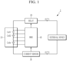
FIG. 1 , the battery system 1 includes abattery 10, arelay 20, acurrent sensor 30, and a battery management system (BMS) 40. - The
battery 10 includes a plurality of battery cells Cell1 to Celln that are electrically connected. In some embodiments, the battery cells may be rechargeable batteries. A predetermined number of battery cells may be connected in series to constitute a battery module, and a predetermined number of battery modules may be connected in series and parallel to constitute thebattery 10 to supply desired power. Each of the battery cells Cell1 to Celln is electrically connected to theBMS 40 through wires. - In
FIG. 1 , thebattery 10 includes the plurality of battery cells Cell1 to Celln connected in series, and is connected between two output terminals OUT1 and OUT2 of the battery system 1. Therelay 20 is connected between a positive electrode of thebattery 10 and the output terminal OUT1, and thecurrent sensor 30 is connected between a negative electrode of thebattery 10 and the output terminal OUT2. The constituent elements illustrated inFIG. 1 and a connection relationship between the constituent elements are examples, and the present invention is not limited thereto. - The
relay 20 controls electrical connection between the battery system 1 and an external device. When therelay 20 is turned on, the battery system 1 and the external device are electrically connected to perform charging or discharging, and when therelay 20 is turned off, the battery system 1 and the external device are electrically separated. In this case, the external device may serve as a charger in a charging mode in which thebattery 10 is charged by supplying power, or a load in a discharge mode in which power stored in thebattery 10 is discharged. - The
current sensor 30 is connected in series to a current path between thebattery 10 and the external device. Thecurrent sensor 30 may measure a current flowing through thebattery 10, i.e., a charging current and a discharging current, and may transmit a measurement result to theBMS 40. - The
BMS 40 may collect and analyze various information related to the battery cells Cell1 to Celln to control charging and discharging of the battery cells, cell balancing, a protection operation, and the like, and may control an operation of therelay 20. For example, theBMS 40 may control charging of thebattery 10 in a normal mode (NORMAL MODE) or an eco-friendly mode (ECO MODE) depending on user selection. - In the normal mode (NORMAL MODE), the
battery 10 uses a maximum usable battery capacity (hereinafter, a first battery capacity) within a designed range, and uses a charging method selected by a user among a slow charging method or a rapid charging method to charge thebattery 10. For example, the normal mode (NORMAL MODE) is a method of using and managing thebattery 10 in an initially designed state. - In the eco-friendly mode (ECO MODE), the
battery 10 uses a narrower battery capacity (hereinafter, second battery capacity) than the maximum usable battery capacity in a designed range, and charges thebattery 10 by a slow charging method. For example, the eco-friendly mode (ECO MODE) is a battery management method for extending the cycle-life of thebattery 10, and may be set by user selection. That is, the eco-friendly mode (ECO MODE) is a battery management method that slows down an aging rate of thebattery 10 by limiting excessive use of the battery capacity and the rapid charging method. - A state of charge (SOC) is an amount of energy that is currently stored in the
battery 10, and a unit thereof is percent (%). When thebattery 10 is fully charged, the state of charge SOC is 100 %. When thebattery 10 is completely discharged, the state of charge (SOC) is 0 %. When the fully chargedbattery 10 starts to be discharged, the state of charge (SOC) decreases to 100 %, 80 %, 60 %, etc. as time elapses. In the meantime, the state of charge (SOC) cannot be directly measured, and theBMS 40 may estimate the state of charge (SOC) by an indirect method such as a conventionally known current integration method or a voltage measurement method. TheBMS 40 may estimate the state of charge (SOC) in a predetermined period or in real time. - The battery capacity is a total amount of energy that the
battery 10 can store, and the unit is ampere-hours (Ah) and represents how long a constant current can flow. For example, when a current of 1 A flows for 1 hour, the battery capacity is 1 AH, and when it flows for 2 hours, the battery capacity is 2 AH. - According to an embodiment, the first battery capacity may include a battery capacity having a range between a first lower limit SOC and a first upper limit SOC provided in a design and production process of the
battery 10. For example, the first battery capacity may include a battery capacity defined as 0 % to 100 %, or substantially in a range of 2 % to 96 % in consideration of a design margin, resistance, calculation error, and the like. The second battery capacity may include a battery capacity in a narrower region than the first battery capacity in order to slow the aging rate of thebattery 10. Specifically, the second battery capacity may include a battery capacity having a range between a second lower limit SOC that is a predetermined magnitude that is greater than the first lower limit SOC and a second upper limit SOC that is a predetermined magnitude that is smaller than the first upper limit SOC. For example, the second battery capacity may include a battery capacity defined as a range between 30 % and 80 %. - In the normal mode (NORMAL MODE), the
BMS 40 enters a charging mode for supplying power to thebattery 10 when the state of charge (SOC) reaches the first lower limit SOC (e.g., 2 %). When a real-time state of charge (SOC) reaches the first upper limit SOC (e.g., 96 %) by supplying power tobattery 10, theBMS 40 may end the charging mode. In addition, in the eco-friendly mode (ECO MODE), theBMS 40 enters a charging mode for supplying power to thebattery 10 when the state of charge (SOC) reaches the second lower limit SOC (e.g., 30 %). When a real-time state of charge (SOC) reaches the second upper limit SOC (e.g., 80 %) by supplying power tobattery 10, theBMS 40 may end the charging mode. - Slow charging and rapid charging are battery charging methods that are divided depending on the charging speed. The slow charging is a slow charging method for completing the charging of the
battery 10 after exceeding a predetermined reference time. The rapid charging is a fast charging method for completing the charging of thebattery 10 within a predetermined reference time. - In the meantime, when using the battery at a maximum capacity, e.g., when the first lower limit SOC (e.g., 2 %) and the first upper limit SOC (e.g., 96 %) are repeatedly used, or when using an extended battery capacity (1 % to 97 % or 0 % to 99 %), aging of the
battery 10 may be accelerated. In addition, when thebattery 10 is charged by the rapid charging method, the aging of thebattery 10 may be accelerated compared to when thebattery 10 is charged by the slow charging method. - As the
battery 10 ages with use after being manufactured, a total amount of storable energy (battery capacity) also decreases. A state of health (SOH) is a performance index that is obtained by comparing an ideal battery state with a current battery state. For example, although thebattery 10 initially had a battery capacity of 1000 mAh, the battery capacity may decrease to 850 mAh after use for a predetermined period of time. Then, the battery state of health (SOH) becomes 85 %. - For reference, when the battery state of health (SOH) is 100 %, states of charge (SOC) at the time of full charge and full discharge of the
battery 10 are 100 % and 0 %, respectively. In addition, when the battery state of health (SOH) is 85 %, the states of charge (SOC) at the time of full charge and full discharge of thebattery 10 are 100 % and 0 %, respectively. That is, the state of charge (SOC) is 100 % when the energy that can be filled in thebattery 10 is fully filled, and is 0 % when the energy is exhausted, regardless of the state of health (SOH) of the battery. However, thebattery 10 with a battery state of health (SOH) of 100 % can supply a total of 1000 mAh of energy after being fully charged, whereas thebattery 10 with a battery state of health (SOH) of 85 % can only supply a total of 850 mAh energy after being fully charged. - That is, the battery capacity decreases in response to the battery state of health (SOH). For example, a time when the battery state of health (SOH) is decreased to a predetermined reference value, e.g., 80 %, may be regarded as a battery replacement time. When the battery state of health (SOH) falls below 80 %, the battery capacity is rapidly deteriorated and the
battery 10 cannot perform its original role. -
FIG. 2A and 2B illustrate views for describing a normal mode according to an embodiment, andFIG. 3A and 3B illustrate views for describing an eco-friendly mode according to an embodiment. - According to an embodiment, a first key Key_1 for executing the eco-friendly mode (ECO MODE) may be provided on a user interface (not illustrated). When a user selects (ON) or non-selects (OFF), the first key Key_1 that performs the eco-friendly mode (ECO MODE), the
BMS 40 may control the charging of thebattery 10 in the eco-friendly mode (ECO MODE) depending on user selection (ON) or the normal mode (NORMAL MODE) depending on non-selection (OFF). For example, theBMS 40 may receive a first key-on signal for selecting the first key Key_1 or a first key-off signal for not selecting the first key Key_1 from an electronic control unit (ECU). - According to another embodiment, the first key Key_1 for executing the eco-friendly mode (ECO MODE) and a second key Key_2 for executing the normal mode (NORMAL MODE), which can be manipulated by the user, may be provided in a user interface. When the user selects (ON) of the first key Key_1 for executing the eco-friendly mode (ECO MODE), the
BMS 40 may control the charging of thebattery 10 in the eco-friendly mode (ECO MODE). When the user selects (ON) of the second key Key_2 for executing the normal mode (NORMAL MODE), theBMS 40 may control the charging of thebattery 10 in the normal mode (NORMAL MODE). For example, theBMS 40 may receive the first key-on signal for selecting the first key Key_1 or a second key-on signal for selecting the second key Key_2 of the normal mode (NORMAL MODE) from the electronic control unit (ECU). - Referring to
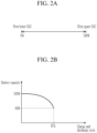
FIG. 2A , in an ON state of the normal mode (NORMAL MODE), the first battery capacity is set to a usable battery capacity (hereinafter, the available battery capacity), and rapid charging is enabled. Accordingly, theBMS 40 may control the charging of thebattery 10 in a first battery capacity range by the fast charging or slow charging method depending on the user selection. - Referring to
FIG. 2B , when thebattery 10 is used and managed in the normal mode (NORMAL MODE), an end of life (EOL) of thebattery 10 may be determined as a time when the available battery capacity reaches a predetermined reference value (80 %) compared to an initial state (100 %). That is, when the battery state of health (SOH) reaches 80 %, thebattery 10 should be discarded. In this case, the end of life (EOL) may be determined depending on a number of charge and discharge cycles. For example, a lithium-ion battery is determined to have reached the end of life (EOL) when 300 to 500 charge and discharge cycles have elapsed. - Referring to
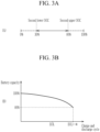
FIG. 3A , in the ON state of the eco-friendly mode (ECO MODE), the second battery capacity is set to an available battery capacity, and the fast charging method is disabled. Accordingly, theBMS 40 may control the charging of thebattery 10 in a second battery capacity range by the slow charging method. In this case, the second battery capacity may be set to a battery capacity in a range that is smaller than the first battery capacity. - Referring to
FIG. 3B , when thebattery 10 is used and managed in the eco-friendly mode (ECO MODE), an end of life (EOL+α) of thebattery 10 may be extended for a predetermined period of time α than when thebattery 10 is used and managed in the normal mode (NORMAL MODE). -
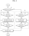
FIG. 4 illustrates a flowchart describing a method of extending cycle-life of a battery by charging the battery in a normal mode or an eco-friendly mode depending on user selection according to an embodiment. - Hereinafter, a battery management method and a battery system providing the method will be described with reference to
FIG. 1 to FIG. 4 . - Referring to
FIG. 4 , theBMS 40 determines whether the eco-friendly mode (ECO MODE) is in an on state by user selection (S10). - According to an embodiment, a first key Key_1 for executing the eco-friendly mode (ECO MODE) may be provided on a user interface (not illustrated). When a user selects the first key Key_1, the
BMS 40 may determine the eco-friendly mode (ECO MODE), while when the user does not select the first key Key_1, theBMS 40 may determine the normal mode (NORMAL MODE). That is, when the user does not take any action, theBMS 40 may determine the normal mode (NORMAL MODE). For example, theBMS 40 may receive a first key-on signal for indicating selection of the first key Key_1 or a first key-off signal for indicating non-selection of the first key Key_1 from an electronic control unit (ECU). - According to another embodiment, the first key Key_1 for executing the eco-friendly mode (ECO MODE) and a second key Key_2 for executing the normal mode (NORMAL MODE) may be provided in a user interface. When the user selects the first key Key_1, the
BMS 40 may determine the eco-friendly mode (ECO MODE), while when the user does not select the second key Key_2, theBMS 40 may determine the normal mode (NORMAL MODE). For example, theBMS 40 may receive the first key-on signal for selecting the first key Key_1 or a second key-on signal for selecting the second key Key_2 of the normal mode (NORMAL MODE) from the electronic control unit (ECU). - Next, when the eco-friendly mode (ECO MODE) is in an off state (S10, No), the
BMS 40 controls the charging of thebattery 10 in the normal mode (NORMAL MODE) (S20). - In step S20, first, the
BMS 40 diagnoses whether a current state of charge (SOC) reaches a first lower limit SOC of the first battery capacity (S21). - The normal mode (NORMAL MODE) is a method of managing the
battery 10 as designed. The normal mode (NORMAL MODE) uses the first battery capacity, which is a maximum battery capacity that is usable in the designed range. In this case, the first battery capacity may be a battery capacity having a range between a first lower limit SOC and a first upper limit SOC provided in a design and production process of thebattery 10. Assuming an ideal state, the first battery capacity may include a battery capacity defined in a range between 0 % and 100 %. TheBMS 40 may calculate the current state of charge (SOC) by estimating the state of charge (SOC) in a predetermined period or in real time. - In step S20, when the state of charge SOC reaches the first lower limit SOC (S21, Yes), the
BMS 40 enters a charging mode for supplying power to the battery 10 (S22). - The
BMS 40 may control the charging of thebattery 10 in a first battery capacity range by the fast charging or slow charging method depending on the user selection. For example, when the user selects the rapid charging, theBMS 40 may control power to be supplied to thebattery 10 through rapid charging. - According to an embodiment, when there is no user selection of the charging method, the
BMS 40 may request the user to select the charging method through the electronic control unit (ECU). The electronic control unit (ECU) may control a message requesting selection of one of the fast charging and the slow charging method to be displayed on a user interface. - In step S20, the
BMS 40 diagnoses whether a current state of charge (SOC) reaches a first upper limit SOC of the first battery capacity (S23). - In the charging mode, the
battery 10 receives power from an external device, and the state of charge (SOC) increases as time elapses. For example, in the case where charging is started when the state of charge (SOC) is 0 %, the state of charge (SOC) may gradually increase to 10 %, 30 %, or 50 % as time elapses. - Next, when the eco-friendly mode (ECO MODE) is in an on state (S10, Yes), the
BMS 40 controls the charging of thebattery 10 in the eco-friendly mode (ECO MODE) (S30). - In step S30, first, the
BMS 40 diagnoses whether the state of charge (SOC) reaches a second lower limit SOC of the second battery capacity (S31). - The eco-friendly mode (ECO MODE) is a battery management method for extending the cycle-life of the
battery 10, and may be set by user selection. In the eco-friendly mode (ECO MODE), the second battery capacity, which is a battery capacity in a narrower region than that of the first battery capacity, is used. In this case, the second battery capacity may include a battery capacity having a range between a second lower limit SOC that is a predetermined magnitude that is greater than the first lower limit SOC and a second upper limit SOC that is a predetermined magnitude that is smaller than the first upper limit SOC. For example, the second battery capacity may include a battery capacity defined as a range between 30 % and 80 %. - Referring to
FIG. 3A , the first lower limit SOC of the first battery capacity is smaller than the second lower limit SOC of the second battery capacity, and the first upper limit SOC is greater than the second upper limit SOC of the second battery capacity. - In step S30, when the state of charge SOC reaches the second lower limit SOC (S31, Yes), the
BMS 40 enters a charging mode for supplying power to the battery 10 (S32). - Since the rapid charging method is disabled, the
BMS 40 may control the charging of thebattery 10 in the second battery capacity range by the slow charging method. When the state of charge (SOC) reaches the second lower limit SOC, e.g., 30 %, theBMS 40 may control thebattery 10 to be charged without further discharging. - In step S30, the
BMS 40 diagnoses whether the state of charge (SOC) reaches the second upper limit SOC of the second battery capacity (S33). - Next, when the current state of charge (SOC) reaches the first upper limit SOC or the second upper limit SOC (S23, Yes), the
BMS 40 may end the charging mode S40. - When the
battery 10 is fully charged up to the first upper limit SOC, theBMS 40 may end charging of the battery 10(S40). For example, theBMS 40 may end the charging of thebattery 10 when the state of charge (SOC) reaches 100 %. - When the
battery 10 is fully charged up to the second upper limit SOC, theBMS 40 may end charging of the battery 10(S40). For example, in the case where charging is started when the state of charge (SOC) is 30 %, the state of charge (SOC) may gradually increase to 30 % or 70 % as time elapses. When the state of charge (SOC) reaches the second upper limit SOC, e.g., 80%, theBMS 40 may end the charging mode such that thebattery 10 is no longer charged. - While this invention has been described in connection with what is presently considered to be practical embodiments, it is to be understood that the invention is not limited to the disclosed embodiments, but, on the contrary, is intended to cover various modifications and equivalent arrangements included within the scope of the appended claims.
Claims (7)
- A battery system, comprising:a battery; anda battery management system, BMS, configured to control charging of the battery depending on a normal mode where the battery is charged with a first battery capacity between a first lower limit state of charge, SOC, and a first upper limit SOC or an eco-friendly mode, ECO MODE, where the battery is charged with a second battery capacity between a second lower limit SOC and a second upper limit SOC,wherein the first lower limit SOC is smaller than the second lower limit SOC, andthe first upper limit SOC is greater than the second upper limit SOC,wherein the BMS is configured to, in an on state of the normal mode, calculate a current SOC by estimating a SOC of the battery every predetermined period, and start charging of the battery when the current SOC reaches the first lower limit SOC and end the charging of the battery when the current SOC reaches the first upper limit SOC,wherein the BMS is configured to, in an on state of the normal mode, control charging of the battery by using a rapid charging method of charging the battery for completing the charging of the battery from when the current SOC reaches the first lower limit SOC until when the current SOC reaches the first upper limit SOC within a predetermined reference time or performing a slow charging method of charging the battery for completing the charging of the battery from when the current SOC reaches the first lower limit SOC until when the current SOC reaches the first upper limit SOC after exceeding the predetermined reference time,wherein the BMS is configured to, in an on state of the normal mode, control the charging of the battery by the rapid charging method or the slow charging method depending on user selection.
- The battery system of claim 1, wherein the BMS is configured to,calculate a current SOC by estimating a SOC of the battery every predetermined period, and in an on state of the eco-friendly mode,start charging of the battery when the current SOC reaches the second lower limit SOC and end the charging of the battery when the current SOC reaches the second upper limit SOC.
- The battery system of claim 2, wherein the BMS is configured to,in an on state of the eco-friendly mode,control charging of the battery by using the slow charging method of charging the battery for completing the charging of the battery from when the current SOC reaches the second lower limit SOC until when the current SOC reaches the second upper limit SOC after exceeding the predetermined reference time.
- The battery system of claim 1, wherein the BMS is configured to,determine that the eco-friendly mode is in an on state when receiving a key-on signal of the eco-mode for indicating selection of the eco-friendly mode by a user, anddetermine that the normal mode is in an on state when receiving a key-off signal of the eco-friendly mode for indicating non-selection of the eco-friendly mode by the user.
- A battery management method for a battery management system, BMS, configured to manage a battery by controlling charging of the battery depending on a normal mode where the battery is charged with a first battery capacity between a first lower limit state of charge, SOC, and a first upper limit SOC or an eco-friendly mode where the battery is charged with a second battery capacity between a second lower limit SOC and a second upper limit SOC, the method comprising:determining whether the eco-friendly mode, ECO MODE, is in an on state;starting and controlling the charging of the battery when a current SOC that is estimated every predetermined period reaches the first lower limit SOC or the second lower limit SOC depending on a determination result thereof; andending the charging of the battery when the current SOC reaches the first upper limit SOC or the second upper limit SOC,wherein the first lower limit SOC is smaller than the second lower limit SOC, and the first upper limit SOC is greater than the second upper limit SOC,wherein the starting and controlling of the charging of the battery includes:diagnosing whether or not the current SOC reaches the first lower limit SOC when the normal mode is in an on state as a result of the determination;starting the charging of the battery by using a rapid charging method of charging the battery for completing the charging of the battery from when the current SOC reaches the first lower limit SOC until when the current SOC reaches the first upper limit SOC within a predetermined reference time or a slow charging method of charging the battery for completing the charging of the battery from when the current SOC reaches the first lower limit SOC until when the current SOC reaches the first upper limit SOC after exceeding the predetermined reference time when reaching it as a result of the diagnosis; anddiagnosing whether the current SOC reaches the first upper limit SOC,wherein the starting of the charging of the battery includescontrolling the charging of the battery by the rapid charging method or the slow charging method depending on user selection.
- A battery management method of claim 5, wherein
the starting and controlling of the charging of the battery includes:diagnosing whether or not the current SOC reaches the second lower limit SOC when the eco-friendly mode is in an on state as a result of the determination;starting the charging of the battery by using the slow charging method of charging the battery for completing the charging of the battery from when the current SOC reaches the second lower limit SOC until when the current SOC reaches the second upper limit SOC after exceeding the predetermined reference time when reaching it as a result of the diagnosis; anddiagnosing whether the current SOC reaches the second upper limit SOC. - The battery management method of claim 5, wherein the determining of whether the eco-friendly mode, ECO MODE, is in the on state includes:
determining that the eco-friendly mode is in an on state when receiving a key-on signal of the eco-mode for indicating selection of the eco-friendly mode by a user, and determining that the normal mode is in an on state when receiving a key-off signal of the eco-friendly mode for indicating non-selection of the eco-friendly mode by the user.
Applications Claiming Priority (2)
| Application Number | Priority Date | Filing Date | Title |
|---|---|---|---|
| KR1020200087773A KR20220009273A (en) | 2020-07-15 | 2020-07-15 | Method for battery management and battery system providing the same |
| PCT/KR2021/008740 WO2022014953A1 (en) | 2020-07-15 | 2021-07-08 | Method for battery management and battery system providing same |
Publications (3)
| Publication Number | Publication Date |
|---|---|
| EP4032746A1 EP4032746A1 (en) | 2022-07-27 |
| EP4032746A4 EP4032746A4 (en) | 2023-01-18 |
| EP4032746B1 true EP4032746B1 (en) | 2024-09-18 |
Family
ID=79555532
Family Applications (1)
| Application Number | Title | Priority Date | Filing Date |
|---|---|---|---|
| EP21842305.1A Active EP4032746B1 (en) | 2020-07-15 | 2021-07-08 | Method for battery management and battery system providing same |
Country Status (8)
| Country | Link |
|---|---|
| US (1) | US12351058B2 (en) |
| EP (1) | EP4032746B1 (en) |
| JP (1) | JP7509360B2 (en) |
| KR (1) | KR20220009273A (en) |
| CN (1) | CN114616125B (en) |
| ES (1) | ES2994645T3 (en) |
| HU (1) | HUE068438T2 (en) |
| WO (1) | WO2022014953A1 (en) |
Families Citing this family (5)
| Publication number | Priority date | Publication date | Assignee | Title |
|---|---|---|---|---|
| CN114598015B (en) * | 2022-03-08 | 2025-05-16 | 兰州理工大学 | Submodule control method for MMC retired power battery energy storage system |
| WO2024188465A1 (en) * | 2023-03-16 | 2024-09-19 | ABB E-mobility B.V. | Systems and methods for controlling a charging session |
| US20240322274A1 (en) * | 2023-03-21 | 2024-09-26 | Mediatek Inc. | Method for determining State of Charge of battery module and portable electronic device utilizing the same |
| CN116872792B (en) * | 2023-08-22 | 2024-04-02 | 杭州鸿途智慧能源技术有限公司 | Hybrid power control system based on quick replacement energy supplementing power battery |
| CN119408458B (en) * | 2024-11-21 | 2026-03-31 | 东风汽车有限公司东风日产乘用车公司 | Power battery capacity correction methods, storage media and electronic devices |
Family Cites Families (30)
| Publication number | Priority date | Publication date | Assignee | Title |
|---|---|---|---|---|
| JP2000134719A (en) | 1998-10-29 | 2000-05-12 | Isuzu Motors Ltd | Battery charging control device for parallel hybrid electric vehicle |
| JP2005312224A (en) | 2004-04-23 | 2005-11-04 | Toyota Industries Corp | Battery charging apparatus |
| JP4241837B2 (en) | 2007-01-15 | 2009-03-18 | トヨタ自動車株式会社 | Vehicle and control method thereof |
| CN101468610B (en) * | 2007-12-28 | 2011-03-30 | 比亚迪股份有限公司 | A charging control device and method for a hybrid vehicle |
| JP4805328B2 (en) | 2008-10-31 | 2011-11-02 | 本田技研工業株式会社 | Electric vehicle |
| JP2010201987A (en) * | 2009-02-27 | 2010-09-16 | Mitsubishi Heavy Ind Ltd | Drive control device of hybrid vehicle |
| US8712619B2 (en) | 2009-11-17 | 2014-04-29 | Toyota Jidosha Kabushiki Kaisha | Vehicle and method for controlling vehicle |
| EP2482379A4 (en) | 2009-12-01 | 2014-04-09 | Murata Manufacturing Co | Antenna matching device, antenna device, and mobile communication terminal |
| US8629657B2 (en) * | 2009-12-31 | 2014-01-14 | Tesla Motors, Inc. | State of charge range |
| JP5732766B2 (en) | 2010-07-23 | 2015-06-10 | トヨタ自動車株式会社 | Vehicle control apparatus and control method |
| US8937452B2 (en) * | 2011-02-04 | 2015-01-20 | GM Global Technology Operations LLC | Method of controlling a state-of-charge (SOC) of a vehicle battery |
| JP5877360B2 (en) | 2011-05-26 | 2016-03-08 | パナソニックIpマネジメント株式会社 | Storage battery control system |
| KR101825617B1 (en) | 2011-12-27 | 2018-02-06 | 주식회사 엘지화학 | Apparatus and method for changing using-band of battery |
| KR101512879B1 (en) | 2012-04-25 | 2015-04-16 | 엘에스산전 주식회사 | A system for charging electric vehicle |
| CN102856601A (en) | 2012-08-22 | 2013-01-02 | 杭州杰能动力有限公司 | Method and system for adjusting real-time battery capacity during automobile charging and electric automobile |
| JP2014143815A (en) | 2013-01-23 | 2014-08-07 | Konica Minolta Inc | Electronic equipment and image forming apparatus |
| JP2014147197A (en) * | 2013-01-29 | 2014-08-14 | Hitachi Automotive Systems Ltd | Battery control device |
| KR101488586B1 (en) | 2013-03-04 | 2015-02-02 | 주식회사 엘지씨엔에스 | Method and system of dynamic charging |
| JP5683627B2 (en) | 2013-03-22 | 2015-03-11 | トヨタ自動車株式会社 | Power control device |
| JP5825288B2 (en) * | 2013-04-08 | 2015-12-02 | トヨタ自動車株式会社 | Hybrid vehicle |
| KR101592742B1 (en) | 2014-07-28 | 2016-02-18 | 현대자동차주식회사 | Charging control method for eco-friendly vehicle |
| KR101622194B1 (en) | 2014-10-31 | 2016-05-18 | 영화테크(주) | Battery Charging Apparatus for Electric Vehicles Having Battery Protection Function |
| US9969293B2 (en) | 2015-03-30 | 2018-05-15 | Ford Global Technologies, Llc | Battery thermal conditioning to extend battery useful life in electrified vehicles |
| JP6304165B2 (en) | 2015-07-31 | 2018-04-04 | トヨタ自動車株式会社 | Control device for hybrid vehicle |
| WO2017042973A1 (en) | 2015-09-11 | 2017-03-16 | 株式会社東芝 | Storage battery system, method, and program |
| CN105818705B (en) | 2016-03-25 | 2018-11-06 | 郑州宇通客车股份有限公司 | Electric vehicle charge control method and electric vehicle charge control device |
| KR101826617B1 (en) | 2016-05-26 | 2018-02-08 | 성창산업 주식회사 | Nutrient solution culture apparatus for vinyl house |
| JP2019030161A (en) | 2017-08-01 | 2019-02-21 | 大阪瓦斯株式会社 | Distribution-type power supply system |
| JP6919720B2 (en) | 2017-12-15 | 2021-08-18 | 日産自動車株式会社 | Hybrid vehicle control method and control device |
| WO2019120570A1 (en) | 2017-12-22 | 2019-06-27 | Volvo Truck Corporation | A method of controlling a state of charge operation range of a vehicle electrical system |
-
2020
- 2020-07-15 KR KR1020200087773A patent/KR20220009273A/en not_active Ceased
-
2021
- 2021-07-08 EP EP21842305.1A patent/EP4032746B1/en active Active
- 2021-07-08 US US17/769,866 patent/US12351058B2/en active Active
- 2021-07-08 WO PCT/KR2021/008740 patent/WO2022014953A1/en not_active Ceased
- 2021-07-08 JP JP2022520021A patent/JP7509360B2/en active Active
- 2021-07-08 HU HUE21842305A patent/HUE068438T2/en unknown
- 2021-07-08 ES ES21842305T patent/ES2994645T3/en active Active
- 2021-07-08 CN CN202180006177.0A patent/CN114616125B/en active Active
Also Published As
| Publication number | Publication date |
|---|---|
| US20220388417A1 (en) | 2022-12-08 |
| HUE068438T2 (en) | 2024-12-28 |
| ES2994645T3 (en) | 2025-01-28 |
| CN114616125A (en) | 2022-06-10 |
| KR20220009273A (en) | 2022-01-24 |
| JP2022551065A (en) | 2022-12-07 |
| CN114616125B (en) | 2024-05-14 |
| US12351058B2 (en) | 2025-07-08 |
| EP4032746A1 (en) | 2022-07-27 |
| JP7509360B2 (en) | 2024-07-02 |
| WO2022014953A1 (en) | 2022-01-20 |
| EP4032746A4 (en) | 2023-01-18 |
Similar Documents
| Publication | Publication Date | Title |
|---|---|---|
| EP4032746B1 (en) | Method for battery management and battery system providing same | |
| JP3964635B2 (en) | Memory effect detection method and solution | |
| US9358899B2 (en) | Method for revitalizing and increasing lithium ion battery capacity | |
| KR101245788B1 (en) | Method and device for controlling the operating point of a battery | |
| JP5341823B2 (en) | Lithium ion secondary battery degradation judgment system and degradation judgment method | |
| CN101536285B (en) | Device and method for detecting abnormality of electric storage element | |
| JP4670831B2 (en) | Battery capacity detection method and apparatus for electric vehicle and electric vehicle maintenance method | |
| US8749201B2 (en) | Battery pack capacity learn algorithm | |
| JP5356439B2 (en) | Charge control device and charge control method | |
| US8674659B2 (en) | Charge control device and vehicle equipped with the same | |
| EP2993758A1 (en) | Charge control device and charge control method | |
| US20180358819A1 (en) | A method and system for balancing a battery pack | |
| JP2002369391A (en) | Method and apparatus for controlling remaining capacity of secondary battery | |
| JP2010098866A (en) | Imbalance determination circuit, imbalance reduction circuit, battery power supply, and imbalance evaluation method | |
| JPWO2012137456A1 (en) | Remaining life judgment method | |
| JP2003079059A (en) | In-vehicle battery controller | |
| KR101567557B1 (en) | Voltage balancing apparatus and method of secondary battery cells | |
| JP2004031014A (en) | Method and apparatus for calculating maximum charge / discharge power of battery pack including parallel connected batteries | |
| JP2026015351A (en) | Energy storage device, energy storage system, internal resistance estimation method, and computer program | |
| JP2013031248A (en) | Battery device hysteresis reduction system | |
| WO2013105139A1 (en) | Method for controlling and device for controlling secondary battery | |
| KR20250119192A (en) | Battery management apparatus and battery management method | |
| KR20250062887A (en) | Hybrid battery system | |
| JP5257173B2 (en) | In-vehicle power supply | |
| CN116316935A (en) | Power management method and vehicle auxiliary power supply |
Legal Events
| Date | Code | Title | Description |
|---|---|---|---|
| STAA | Information on the status of an ep patent application or granted ep patent |
Free format text: STATUS: THE INTERNATIONAL PUBLICATION HAS BEEN MADE |
|
| PUAI | Public reference made under article 153(3) epc to a published international application that has entered the european phase |
Free format text: ORIGINAL CODE: 0009012 |
|
| STAA | Information on the status of an ep patent application or granted ep patent |
Free format text: STATUS: REQUEST FOR EXAMINATION WAS MADE |
|
| 17P | Request for examination filed |
Effective date: 20220420 |
|
| AK | Designated contracting states |
Kind code of ref document: A1 Designated state(s): AL AT BE BG CH CY CZ DE DK EE ES FI FR GB GR HR HU IE IS IT LI LT LU LV MC MK MT NL NO PL PT RO RS SE SI SK SM TR |
|
| A4 | Supplementary search report drawn up and despatched |
Effective date: 20221220 |
|
| RIC1 | Information provided on ipc code assigned before grant |
Ipc: B60L 58/16 20190101ALI20221214BHEP Ipc: H01M 10/42 20060101ALI20221214BHEP Ipc: H02J 7/00 20060101ALI20221214BHEP Ipc: H01M 10/44 20060101ALI20221214BHEP Ipc: B60L 53/10 20190101ALI20221214BHEP Ipc: B60L 58/13 20190101AFI20221214BHEP |
|
| DAV | Request for validation of the european patent (deleted) | ||
| DAX | Request for extension of the european patent (deleted) | ||
| RIC1 | Information provided on ipc code assigned before grant |
Ipc: B60L 58/16 20190101ALI20240322BHEP Ipc: H01M 10/42 20060101ALI20240322BHEP Ipc: H02J 7/00 20060101ALI20240322BHEP Ipc: H01M 10/44 20060101ALI20240322BHEP Ipc: B60L 53/10 20190101ALI20240322BHEP Ipc: B60L 58/13 20190101AFI20240322BHEP |
|
| GRAP | Despatch of communication of intention to grant a patent |
Free format text: ORIGINAL CODE: EPIDOSNIGR1 |
|
| STAA | Information on the status of an ep patent application or granted ep patent |
Free format text: STATUS: GRANT OF PATENT IS INTENDED |
|
| INTG | Intention to grant announced |
Effective date: 20240503 |
|
| GRAS | Grant fee paid |
Free format text: ORIGINAL CODE: EPIDOSNIGR3 |
|
| GRAA | (expected) grant |
Free format text: ORIGINAL CODE: 0009210 |
|
| STAA | Information on the status of an ep patent application or granted ep patent |
Free format text: STATUS: THE PATENT HAS BEEN GRANTED |
|
| AK | Designated contracting states |
Kind code of ref document: B1 Designated state(s): AL AT BE BG CH CY CZ DE DK EE ES FI FR GB GR HR HU IE IS IT LI LT LU LV MC MK MT NL NO PL PT RO RS SE SI SK SM TR |
|
| P01 | Opt-out of the competence of the unified patent court (upc) registered |
Free format text: CASE NUMBER: APP_46768/2024 Effective date: 20240813 |
|
| REG | Reference to a national code |
Ref country code: GB Ref legal event code: FG4D |
|
| REG | Reference to a national code |
Ref country code: CH Ref legal event code: EP |
|
| REG | Reference to a national code |
Ref country code: IE Ref legal event code: FG4D |
|
| REG | Reference to a national code |
Ref country code: DE Ref legal event code: R096 Ref document number: 602021019104 Country of ref document: DE |
|
| REG | Reference to a national code |
Ref country code: HU Ref legal event code: AG4A Ref document number: E068438 Country of ref document: HU |
|
| REG | Reference to a national code |
Ref country code: LT Ref legal event code: MG9D |
|
| PG25 | Lapsed in a contracting state [announced via postgrant information from national office to epo] |
Ref country code: NO Free format text: LAPSE BECAUSE OF FAILURE TO SUBMIT A TRANSLATION OF THE DESCRIPTION OR TO PAY THE FEE WITHIN THE PRESCRIBED TIME-LIMIT Effective date: 20241218 |
|
| PG25 | Lapsed in a contracting state [announced via postgrant information from national office to epo] |
Ref country code: GR Free format text: LAPSE BECAUSE OF FAILURE TO SUBMIT A TRANSLATION OF THE DESCRIPTION OR TO PAY THE FEE WITHIN THE PRESCRIBED TIME-LIMIT Effective date: 20241219 Ref country code: FI Free format text: LAPSE BECAUSE OF FAILURE TO SUBMIT A TRANSLATION OF THE DESCRIPTION OR TO PAY THE FEE WITHIN THE PRESCRIBED TIME-LIMIT Effective date: 20240918 |
|
| PG25 | Lapsed in a contracting state [announced via postgrant information from national office to epo] |
Ref country code: BG Free format text: LAPSE BECAUSE OF FAILURE TO SUBMIT A TRANSLATION OF THE DESCRIPTION OR TO PAY THE FEE WITHIN THE PRESCRIBED TIME-LIMIT Effective date: 20240918 |
|
| PG25 | Lapsed in a contracting state [announced via postgrant information from national office to epo] |
Ref country code: LV Free format text: LAPSE BECAUSE OF FAILURE TO SUBMIT A TRANSLATION OF THE DESCRIPTION OR TO PAY THE FEE WITHIN THE PRESCRIBED TIME-LIMIT Effective date: 20240918 |
|
| PG25 | Lapsed in a contracting state [announced via postgrant information from national office to epo] |
Ref country code: HR Free format text: LAPSE BECAUSE OF FAILURE TO SUBMIT A TRANSLATION OF THE DESCRIPTION OR TO PAY THE FEE WITHIN THE PRESCRIBED TIME-LIMIT Effective date: 20240918 |
|
| REG | Reference to a national code |
Ref country code: NL Ref legal event code: MP Effective date: 20240918 |
|
| PG25 | Lapsed in a contracting state [announced via postgrant information from national office to epo] |
Ref country code: RS Free format text: LAPSE BECAUSE OF FAILURE TO SUBMIT A TRANSLATION OF THE DESCRIPTION OR TO PAY THE FEE WITHIN THE PRESCRIBED TIME-LIMIT Effective date: 20241218 |
|
| REG | Reference to a national code |
Ref country code: ES Ref legal event code: FG2A Ref document number: 2994645 Country of ref document: ES Kind code of ref document: T3 Effective date: 20250128 |
|
| PG25 | Lapsed in a contracting state [announced via postgrant information from national office to epo] |
Ref country code: RS Free format text: LAPSE BECAUSE OF FAILURE TO SUBMIT A TRANSLATION OF THE DESCRIPTION OR TO PAY THE FEE WITHIN THE PRESCRIBED TIME-LIMIT Effective date: 20241218 Ref country code: NO Free format text: LAPSE BECAUSE OF FAILURE TO SUBMIT A TRANSLATION OF THE DESCRIPTION OR TO PAY THE FEE WITHIN THE PRESCRIBED TIME-LIMIT Effective date: 20241218 Ref country code: LV Free format text: LAPSE BECAUSE OF FAILURE TO SUBMIT A TRANSLATION OF THE DESCRIPTION OR TO PAY THE FEE WITHIN THE PRESCRIBED TIME-LIMIT Effective date: 20240918 Ref country code: HR Free format text: LAPSE BECAUSE OF FAILURE TO SUBMIT A TRANSLATION OF THE DESCRIPTION OR TO PAY THE FEE WITHIN THE PRESCRIBED TIME-LIMIT Effective date: 20240918 Ref country code: GR Free format text: LAPSE BECAUSE OF FAILURE TO SUBMIT A TRANSLATION OF THE DESCRIPTION OR TO PAY THE FEE WITHIN THE PRESCRIBED TIME-LIMIT Effective date: 20241219 Ref country code: FI Free format text: LAPSE BECAUSE OF FAILURE TO SUBMIT A TRANSLATION OF THE DESCRIPTION OR TO PAY THE FEE WITHIN THE PRESCRIBED TIME-LIMIT Effective date: 20240918 Ref country code: BG Free format text: LAPSE BECAUSE OF FAILURE TO SUBMIT A TRANSLATION OF THE DESCRIPTION OR TO PAY THE FEE WITHIN THE PRESCRIBED TIME-LIMIT Effective date: 20240918 |
|
| REG | Reference to a national code |
Ref country code: AT Ref legal event code: MK05 Ref document number: 1724425 Country of ref document: AT Kind code of ref document: T Effective date: 20240918 |
|
| PG25 | Lapsed in a contracting state [announced via postgrant information from national office to epo] |
Ref country code: NL Free format text: LAPSE BECAUSE OF FAILURE TO SUBMIT A TRANSLATION OF THE DESCRIPTION OR TO PAY THE FEE WITHIN THE PRESCRIBED TIME-LIMIT Effective date: 20240918 |
|
| PG25 | Lapsed in a contracting state [announced via postgrant information from national office to epo] |
Ref country code: PT Free format text: LAPSE BECAUSE OF FAILURE TO SUBMIT A TRANSLATION OF THE DESCRIPTION OR TO PAY THE FEE WITHIN THE PRESCRIBED TIME-LIMIT Effective date: 20250120 Ref country code: IS Free format text: LAPSE BECAUSE OF FAILURE TO SUBMIT A TRANSLATION OF THE DESCRIPTION OR TO PAY THE FEE WITHIN THE PRESCRIBED TIME-LIMIT Effective date: 20250118 |
|
| PG25 | Lapsed in a contracting state [announced via postgrant information from national office to epo] |
Ref country code: RO Free format text: LAPSE BECAUSE OF FAILURE TO SUBMIT A TRANSLATION OF THE DESCRIPTION OR TO PAY THE FEE WITHIN THE PRESCRIBED TIME-LIMIT Effective date: 20240918 Ref country code: SM Free format text: LAPSE BECAUSE OF FAILURE TO SUBMIT A TRANSLATION OF THE DESCRIPTION OR TO PAY THE FEE WITHIN THE PRESCRIBED TIME-LIMIT Effective date: 20240918 |
|
| PG25 | Lapsed in a contracting state [announced via postgrant information from national office to epo] |
Ref country code: EE Free format text: LAPSE BECAUSE OF FAILURE TO SUBMIT A TRANSLATION OF THE DESCRIPTION OR TO PAY THE FEE WITHIN THE PRESCRIBED TIME-LIMIT Effective date: 20240918 Ref country code: AT Free format text: LAPSE BECAUSE OF FAILURE TO SUBMIT A TRANSLATION OF THE DESCRIPTION OR TO PAY THE FEE WITHIN THE PRESCRIBED TIME-LIMIT Effective date: 20240918 |
|
| PG25 | Lapsed in a contracting state [announced via postgrant information from national office to epo] |
Ref country code: PL Free format text: LAPSE BECAUSE OF FAILURE TO SUBMIT A TRANSLATION OF THE DESCRIPTION OR TO PAY THE FEE WITHIN THE PRESCRIBED TIME-LIMIT Effective date: 20240918 Ref country code: CZ Free format text: LAPSE BECAUSE OF FAILURE TO SUBMIT A TRANSLATION OF THE DESCRIPTION OR TO PAY THE FEE WITHIN THE PRESCRIBED TIME-LIMIT Effective date: 20240918 |
|
| PG25 | Lapsed in a contracting state [announced via postgrant information from national office to epo] |
Ref country code: IT Free format text: LAPSE BECAUSE OF FAILURE TO SUBMIT A TRANSLATION OF THE DESCRIPTION OR TO PAY THE FEE WITHIN THE PRESCRIBED TIME-LIMIT Effective date: 20240918 Ref country code: SK Free format text: LAPSE BECAUSE OF FAILURE TO SUBMIT A TRANSLATION OF THE DESCRIPTION OR TO PAY THE FEE WITHIN THE PRESCRIBED TIME-LIMIT Effective date: 20240918 |
|
| REG | Reference to a national code |
Ref country code: DE Ref legal event code: R097 Ref document number: 602021019104 Country of ref document: DE |
|
| PG25 | Lapsed in a contracting state [announced via postgrant information from national office to epo] |
Ref country code: DK Free format text: LAPSE BECAUSE OF FAILURE TO SUBMIT A TRANSLATION OF THE DESCRIPTION OR TO PAY THE FEE WITHIN THE PRESCRIBED TIME-LIMIT Effective date: 20240918 |
|
| PGFP | Annual fee paid to national office [announced via postgrant information from national office to epo] |
Ref country code: GB Payment date: 20250624 Year of fee payment: 5 |
|
| PGFP | Annual fee paid to national office [announced via postgrant information from national office to epo] |
Ref country code: FR Payment date: 20250624 Year of fee payment: 5 |
|
| PLBE | No opposition filed within time limit |
Free format text: ORIGINAL CODE: 0009261 |
|
| STAA | Information on the status of an ep patent application or granted ep patent |
Free format text: STATUS: NO OPPOSITION FILED WITHIN TIME LIMIT |
|
| PGFP | Annual fee paid to national office [announced via postgrant information from national office to epo] |
Ref country code: HU Payment date: 20250721 Year of fee payment: 5 |
|
| 26N | No opposition filed |
Effective date: 20250619 |
|
| PG25 | Lapsed in a contracting state [announced via postgrant information from national office to epo] |
Ref country code: SE Free format text: LAPSE BECAUSE OF FAILURE TO SUBMIT A TRANSLATION OF THE DESCRIPTION OR TO PAY THE FEE WITHIN THE PRESCRIBED TIME-LIMIT Effective date: 20240918 |
|
| PGFP | Annual fee paid to national office [announced via postgrant information from national office to epo] |
Ref country code: ES Payment date: 20250822 Year of fee payment: 5 |
|
| PGFP | Annual fee paid to national office [announced via postgrant information from national office to epo] |
Ref country code: DE Payment date: 20250624 Year of fee payment: 5 |
|
| PGFP | Annual fee paid to national office [announced via postgrant information from national office to epo] |
Ref country code: BE Payment date: 20250724 Year of fee payment: 5 |
|
| REG | Reference to a national code |
Ref country code: CH Ref legal event code: H13 Free format text: ST27 STATUS EVENT CODE: U-0-0-H10-H13 (AS PROVIDED BY THE NATIONAL OFFICE) Effective date: 20260224 |
|
| PG25 | Lapsed in a contracting state [announced via postgrant information from national office to epo] |
Ref country code: LU Free format text: LAPSE BECAUSE OF NON-PAYMENT OF DUE FEES Effective date: 20250708 |
|
| PG25 | Lapsed in a contracting state [announced via postgrant information from national office to epo] |
Ref country code: CH Free format text: LAPSE BECAUSE OF NON-PAYMENT OF DUE FEES Effective date: 20250731 |