EP4031847B1 - Dispositif de test d'etancheite pour systeme de transfert a double porte - Google Patents
Dispositif de test d'etancheite pour systeme de transfert a double porte Download PDFInfo
- Publication number
- EP4031847B1 EP4031847B1 EP20804614.4A EP20804614A EP4031847B1 EP 4031847 B1 EP4031847 B1 EP 4031847B1 EP 20804614 A EP20804614 A EP 20804614A EP 4031847 B1 EP4031847 B1 EP 4031847B1
- Authority
- EP
- European Patent Office
- Prior art keywords
- flange
- seal
- door
- sealing
- flanges
- Prior art date
- Legal status (The legal status is an assumption and is not a legal conclusion. Google has not performed a legal analysis and makes no representation as to the accuracy of the status listed.)
- Active
Links
Images


Classifications
-
- G—PHYSICS
- G01—MEASURING; TESTING
- G01M—TESTING STATIC OR DYNAMIC BALANCE OF MACHINES OR STRUCTURES; TESTING OF STRUCTURES OR APPARATUS, NOT OTHERWISE PROVIDED FOR
- G01M3/00—Investigating fluid-tightness of structures
- G01M3/02—Investigating fluid-tightness of structures by using fluid or vacuum
- G01M3/26—Investigating fluid-tightness of structures by using fluid or vacuum by measuring rate of loss or gain of fluid, e.g. by pressure-responsive devices, by flow detectors
- G01M3/28—Investigating fluid-tightness of structures by using fluid or vacuum by measuring rate of loss or gain of fluid, e.g. by pressure-responsive devices, by flow detectors for pipes, cables or tubes; for pipe joints or seals; for valves ; for welds
- G01M3/2853—Investigating fluid-tightness of structures by using fluid or vacuum by measuring rate of loss or gain of fluid, e.g. by pressure-responsive devices, by flow detectors for pipes, cables or tubes; for pipe joints or seals; for valves ; for welds for pipe joints or seals
- G01M3/2869—Investigating fluid-tightness of structures by using fluid or vacuum by measuring rate of loss or gain of fluid, e.g. by pressure-responsive devices, by flow detectors for pipes, cables or tubes; for pipe joints or seals; for valves ; for welds for pipe joints or seals for seals not incorporated in a pipe joint
-
- G—PHYSICS
- G01—MEASURING; TESTING
- G01M—TESTING STATIC OR DYNAMIC BALANCE OF MACHINES OR STRUCTURES; TESTING OF STRUCTURES OR APPARATUS, NOT OTHERWISE PROVIDED FOR
- G01M3/00—Investigating fluid-tightness of structures
- G01M3/02—Investigating fluid-tightness of structures by using fluid or vacuum
- G01M3/26—Investigating fluid-tightness of structures by using fluid or vacuum by measuring rate of loss or gain of fluid, e.g. by pressure-responsive devices, by flow detectors
- G01M3/32—Investigating fluid-tightness of structures by using fluid or vacuum by measuring rate of loss or gain of fluid, e.g. by pressure-responsive devices, by flow detectors for containers, e.g. radiators
- G01M3/3209—Details, e.g. container closure devices
-
- B—PERFORMING OPERATIONS; TRANSPORTING
- B01—PHYSICAL OR CHEMICAL PROCESSES OR APPARATUS IN GENERAL
- B01L—CHEMICAL OR PHYSICAL LABORATORY APPARATUS FOR GENERAL USE
- B01L1/00—Enclosures; Chambers
- B01L1/02—Air-pressure chambers; Air-locks therefor
-
- B—PERFORMING OPERATIONS; TRANSPORTING
- B01—PHYSICAL OR CHEMICAL PROCESSES OR APPARATUS IN GENERAL
- B01L—CHEMICAL OR PHYSICAL LABORATORY APPARATUS FOR GENERAL USE
- B01L2200/00—Solutions for specific problems relating to chemical or physical laboratory apparatus
- B01L2200/14—Process control and prevention of errors
- B01L2200/143—Quality control, feedback systems
- B01L2200/146—Employing pressure sensors
Definitions
- the present invention relates to a sealing test device for a double-door transfer system with increased reliability.
- Such a double-door device provided with a multiple-safety control is for example known from the document FR 2 695 343 .
- Each volume is closed by a door mounted in a flange.
- Each door is secured to its flange by a bayonet connection and the two flanges are intended to be secured to each other by a bayonet connection.
- one of the closed volumes is formed by an insulator and the other volume is formed by a container.
- connection part carried by the insulator is designated alpha part and the connection part carried by the container is designated beta part.
- a technique used to check the sealing of each closed volume uses a device comprising a cavity whose opening is bordered by a thin and relatively rigid O-ring, the seal being intended to be applied against a thin surface of the flange of the alpha part or of the beta part, in order to define with it a test volume, the sealing of which is tested with respect to the interior volume of the container or of the insulator. For example, a given pressure level is generated in the volume and it is checked whether it is stable over time.
- the device is fixed to the alpha part or the beta part, for example by means of screws, so as to press the seal against the surface of the alpha part or the beta part.
- the surface of the beta or alpha part against which the seal is intended to come into contact and seal the test volume with the exterior is exposed to shocks during handling.
- the risks of deterioration of this surface are therefore significant, and the tightness of the test volume with the outside can be prevented, which leads to a result of the negative tightness test which would be false due to the absence of tightness between the joint and the surface.
- the small size of the O-ring and its rigidity may not make it possible to absorb the deterioration of the surface.
- a leak test system for a double-door transfer system between two closed volumes is described in FR2787190 A1 .
- a leak test device which comprises a cavity provided with an opening bordered by an inflatable seal, and means for fixing said device to the part to be tested.
- the device is mounted on the part to be tested and the seal is inflated so as to come into contact with the sealing surface of the part to be tested.
- the implementation of an inflatable seal makes it possible to absorb the deteriorations undergone by the sealing surface. Indeed it offers a great flexibility and can thus marry the defects of the surface.
- the implementation of an inflatable seal has the advantage of reducing friction and facilitating the connection.
- the seal does not risk being damaged during fixing.
- the fixing means use the means used to lock the flanges of the two closed volumes with each other, for example bayonet or lever locking means. Fixing is facilitated and avoids the use of separate means, for example screws.
- the test device is suitable for checking the two closed volumes.
- the subject of the present invention is therefore a device for testing the leaktightness of at least part of a leaktight transfer system with a double door between two closed volumes, said system comprising first and second flanges able to be secured to one another, and first and second doors normally closing openings delimited respectively by the first and second flanges, said device comprising a housing comprising a cavity provided with an opening, means of mechanical connection to at least one of the first and second flanges so that the cavity is closed by one of the first and second flanges and one of the first and second doors, and an inflatable seal intended to come, in the inflated state, into contact with one of the first and second flanges and to provide a seal making it possible to check the seal between the first flange and the first door or the second flange and the second door.
- the device comprises means for inflating the inflatable seal and means for controlling the pressure in the cavity.
- the device may advantageously include a pressure switch to monitor the pressure in the inflatable seal.
- the housing has a groove bordering the opening of the cavity and receiving the inflatable seal.
- the inflatable seal in the deflated state, is housed entirely in the throat.
- first and second flanges of the transfer system include means for locking to each other, and the connection means mechanical advantageously cooperate with the locking means of at least one of the first and second flanges.
- the performance of the tightness test does not require any additional connection means.
- the mechanical connection means are for example of the bayonet type.
- the groove opens into a face of the housing so that the inflatable seal, in the inflated state, comes into contact with a face of the first or second flange substantially parallel to the face of the first or second door.
- the groove opens into the cavity of the casing so that the inflatable seal, in the inflated state, comes into contact with the radially outer periphery of the second flange.
- first flange and the first door are those of an isolator and the second flange and the second door are those of a container.
- the method advantageously includes a step of monitoring the pressure in the inflatable seal throughout the duration of the test.
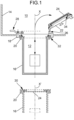
- FIG. 1 a schematic representation of an example of a double door transfer system can be seen.
- the two closed volumes whose tightness is to be tested before their connection correspond respectively to an insulator 10 and to a container 12. It will however be understood that the invention is also applicable in the case where the closed volumes are in a non-limiting manner, for example for one a glove box and for the other a container or a glove box.
- the insulator 10 is delimited by a wall 14 of which only part is visible in the figures. It is equipped, in a conventional manner, for example with remote manipulation means such as telemanipulators and/or gloves (not shown) integral with the wall 14, thanks to which the centralized control mechanism can be maneuvered from inside this cell 10.
- the container 12 is also delimited by a wall 16, as illustrated in particular by the figure 1 .
- the double-door leaktight transfer device mainly comprises an isolator flange 18, a container flange 20, an isolator door 22 normally closing a circular opening delimited by the isolator flange 18, and a container door 24 normally closing an opening delimited by the container flange 20.
- the isolator flange 18 and the container flange 20 are fixed respectively on the wall 14 of the cell 10 and on the wall 16 of container 12.
- the isolator door 22 is hinged to the isolator flange 18 by a hinge 26.
- Means designated generally by the reference 28 make it possible to control the opening and closing of the doors 22 and 24.
- the double-door leaktight transfer system also comprises two other bayonet connections designated respectively by the references 32 and 34.
- the three bayonet connections 30, 32 and 34 are arranged in such a way that after docking the container 20 on the insulator flange 18, a rotation of the container 12 around its axis, for example in the direction of clockwise, has the effect of securing the container flange 20 and the insulator flange 18, of securing the container door 24 and the insulator door 22, and of separating the container door 24 from the container flange 20.
- These last two operations are carried out consecutively, from such that the container is opened only after the container door 24 has been joined to the isolator door 22 to form a double door.
- the assembly formed by the insulator flange and the insulator door is commonly referred to as the “alpha part”.
- the assembly formed by the container flange and the container door is commonly referred to as the “beta part”.
- the double door transfer system has a symmetry of revolution around the X axis which is the axis of the isolator flange.
- the leak test device D1 mounted on the alpha part can be seen in two different states.
- the door 22 of the alpha part comprises a seal 23 mounted on the outer face 22.1 and on the outer periphery of the flange 18.
- the seal 23 extends both on the outer face 22.1 of the door and on its side edge 22.2.
- the seal 23 provides on the one hand the seal between the insulator door 22 and the insulator flange 18, and the seal between the outer face of the insulator door 22 and the outer face of the container door 24, isolating these outer faces from the inside of the closed volumes.
- the seal 23 is fixed to the insulator door 22 by means of an annular bead 25 designated “heel" mounted in an annular groove 21 formed in the insulator door 22.
- the test device D1 is produced to enable the leaks F1 and F2 to be detected.
- the test device D1 comprises a box or head 36 delimiting a cavity 38 comprising a bottom 40, a side wall 42 and an opening 44 opposite the bottom.
- the cavity 38 extends along a longitudinal axis X1.
- Housing 36 has a groove 46 surrounding opening 44 and an inflatable seal 48 mounted in groove 46.
- the inflatable seal 48 advantageously does not protrude from the groove, reducing friction when connecting the test device D1 to the alpha part. Also, the gasket is protected.
- the inflatable seal 48 is glued by its face opposite to its face intended to expand.
- the inflatable seal is for example made of elastomer, for example silicone, styrene butadiene rubber or SBR (styrene-butadiene rubber in English terminology), EPDM (ethylene-propylene-diene monomer), fluoropolymer, for example FKM, hydrogenated nitrile or HNBR (hydrogenated nitrile butadiene rubber in English terminology).
- elastomer for example silicone, styrene butadiene rubber or SBR (styrene-butadiene rubber in English terminology), EPDM (ethylene-propylene-diene monomer), fluoropolymer, for example FKM, hydrogenated nitrile or HNBR (hydrogenated nitrile butadiene rubber in English terminology).
- the diameter of the cavity is chosen so that the inflatable seal 48, in the inflated state, does not cover the potential leak zones F1 and F2 of the insulator.
- the housing is such that it does not come into contact with the seal 23.
- the dimensions of the housing are such that the edge of the groove 46 adjacent to the opening 44, in other words, the partition between the groove 46 and the opening 44 does not come into contact with the seal 23.
- the positioning of the test device D1 is ensured by the fixing means, for example the bayonet locking means; in the connected state the housing and in particular the inner edge of the groove 46 is short enough not to touch the seal 23.
- the test device D1 comprises means 50 for mechanical connection of the housing 36 to the alpha part, in particular of the housing to the insulator flange 18 so that the seal 48, in the inflated state, is in contact with the outer face 18.1 of the insulator flange 18.
- the mechanical connection means 50 cooperate with the means for securing the container flange 20 to the insulator flange 18.
- these are bayonet means.
- the mechanical connection means 50 are identical to those carried by the container flange 20, since the device D1 is mounted on the flange instead of the container.
- the mechanical connection means then comprise lugs 52 penetrating into a groove 54 of the insulator flange 18 and locking the two flanges 18, 20 in translation.
- the mechanical connection means can be of the snap-in type, by screwing, etc.
- Device D1 may also include means 56 for inflating inflatable seal 48.
- the means 56 comprise a fluidic connection 60 between the inflatable seal 48 and for example a pneumatic pump.
- the means 56 comprise monitoring means 64 for monitoring the pressure in the inflatable seal 48 with respect to a predefined setpoint, making it possible to check its condition and/or the mounting of the device on the insulator flange 18.
- the monitoring means 64 comprise a pressure switch.
- the pressure switch monitors a loss of pressure.
- the predefined setpoint corresponds to the inflation pressure value of the seal which has been set beforehand.
- the pressure switch compares the preset set point and the actual seal pressure measurement. When this setpoint/measurement difference exceeds a threshold; for example, if the seal is pierced, the pressure switch sends a signal, for example an alarm in the form of an indicator light.
- a threshold for example, if the seal is pierced
- the pressure switch sends a signal, for example an alarm in the form of an indicator light.
- the pressure switch controls the stopping of the pump when the seal inflation pressure is reached.
- the device D1 comprises for example a pump 62 to generate a certain level of pressure in the sealed cavity and means 58 to monitor the evolution of the pressure level over time in the cavity 38 and perform the sealing test, associated with means to inform the operator of the evolution of the pressure in the form of a screen or a light signal whose color varies depending on whether a leak has been detected or not.
- the test device D1 is first brought closer to the alpha part ( figure 2A ), then is attached to the alpha part ( figure 2B ), the inflatable seal 48 is in a deflated state.
- the mechanical connection means 50 cooperate with the insulator flange 18.
- the connection is obtained by bayonet means.
- the device is approached axially to the insulator flange 18 the X axis and the X1 axis are substantially collinear, then the device housing is pivoted about the X axis, ensuring axial locking of the housing 36 on the insulator flange 18. Since the inflatable seal 48 does not protrude from the groove 46, it does not rub on the insulator flange 18, which reduces friction facilitating assembly and reduces the risk of damage to the seal, for example the risk of it drilling ( figure 2B ).
- the inflatable seal 48 is inflated and comes into contact with the outer face 18.1 of the insulator flange 18 and provides sealing contact in the groove 46 and on the outer face 18.1.
- the pressure in the seal is advantageously monitored ( Fig. 2C ).
- the housing and the inflatable seal 48 define with the alpha part a volume V of which we will check the tightness vis-à-vis the inside of the insulator.
- Control means 58 are activated. A certain pressure is established in the cavity 38 and the evolution of its value is monitored.
- the volume V is typically a few cm 3 .
- a signal warns the operator if the sealing test is positive or negative.
- the inflatable seal 48 is, for example, inflated to a maximum pressure of the order of 2.10 5 Pa and the pressure in the cavity is lowered, for example, to approximately ⁇ 4000 Pa relative to the outside.
- the device D1 according to the invention makes it possible to carry out more reliable tests.
- the inflatable seal is more flexible than an O-ring. It hugs the bearing surface of the insulator flange as it inflates. In the event of defects on the bearing surface, for example a notch or a dent, the inflatable seal adapts and compensates for the surface defects to a certain extent. Thus the risks of false negative results due to a lack of sealing between the test device and the alpha part are greatly reduced.
- test device is more robust, the inflatable seal being protected in the throat and the risks of impact, blows, scratches, cuts, prejudicial to the leak test are reduced.
- an inflatable seal also has the advantage of having a larger contact surface and therefore a larger sealing surface than that of an O-ring.
- test device The assembly of the test device is quick and relatively simple. The risks of erroneous tests are significantly reduced.
- Container flange 20 has a gasket 27 similar to gasket 23 fitted to isolator door 22.
- Device D2 is very similar to device D1 in that it also uses an inflatable seal to delimit a sealed cavity with the beta part. It differs from device D1 in that inflatable seal 148 comes into contact with the radially outer periphery of container flange 20. Device D2 has a longitudinal axis X1'.
- the housing 136 comprises a cavity 138 delimited by a bottom 140 and a side wall 142, an opening 144 of diameter smaller than the inside diameter of the cavity so as to delimit a radial groove 146 in the housing housing the inflatable seal 148.
- the inflatable seal 148 is glued by its face opposite to the face intended to expand.
- the inflatable seal 148 is glued to the bottom of the radial groove 146.
- the examples of materials given for the seal 48 apply to the seal 148.
- the opening 144 has a chamfered radially inner edge facilitating the mounting of the housing on the beta part.
- the assembly of the device on the beta part is such that a clearance is left between the free face of the beta part and the bottom 140 of the cavity 138 so as to provide a test volume V' between the beta part and the device and avoid coming to block the potential leak zones F1' and F2'.
- the volume V' is typically a few cm 3 .
- the test device D2 is configured to connect to a beta part by a bayonet-type connection.
- the device D2 comprises lugs 152 arranged in the throat radial 146 between the bottom of the cavity 138 and the seal 148 and cooperating with the outer peripheral edge of the container flange 20.
- the mechanical connection means can be of the snap-in type, by screwing, etc.
- device D2 may also include means 156 for inflating inflatable seal 148.
- the means 156 comprise a fluidic connection 160 between the inflatable seal 148 and for example a pneumatic pump.
- the means 156 comprise monitoring means 164 for monitoring the pressure in the inflatable seal 148 with respect to a predefined set point, making it possible to check its condition and/or the mounting of the device on the container flange 20.
- the monitoring means 164 include a pressure switch.
- the pressure switch monitors a loss of pressure.
- the predefined setpoint corresponds to the inflation pressure value of the seal which has been set beforehand.
- the pressure switch compares the preset set point and the actual seal pressure measurement. When this setpoint/measurement difference exceeds a threshold; for example, if the seal is pierced, the pressure switch sends a signal, for example an alarm in the form of an indicator light.
- a threshold for example, if the seal is pierced
- the pressure switch sends a signal, for example an alarm in the form of an indicator light.
- the pressure switch controls the stopping of the pump when the seal inflation pressure is reached.
- the device D2 comprises for example a pump 162 to generate a certain level of pressure in the sealed cavity and means 158 to monitor the evolution of the pressure level over time in the cavity 138 and perform the sealing test, associated with means to inform the operator of the evolution of the pressure in the form of a screen or a light signal whose color varies depending on whether a leak has been detected or not.
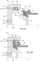
- the beta part leak test with device D2 proceeds in much the same way as the alpha part leak test with device D1.
- the D2 device is locked to the beta part ( Figure 3B ), the inflatable seal 148 is inflated ( Fig. 3C ) delimiting a volume V' whose pressure is controlled.
- the seal comes into contact with a bearing surface housed at the bottom of a groove which is relatively protected from any shocks that a container may suffer during its handling. Furthermore, it is a machined surface which therefore has a good surface finish and the surface is wide relative to the surface of the flange against which the test devices of the prior art come into contact. The risks of a poor seal between the flange of the beta part and the inflatable seal during the test are significantly reduced.
- the device D2 can be configured so that the inflatable seal comes into contact with the front face of the flange, by using a container flange with a larger surface area. It can then be envisaged that the sealing test device of the alpha part is also used to test the sealing of the beta part.
- connection between the test device and the alpha part or the beta part is obtained by bayonet-type means, which are the means for locking the insulator and container flanges with each other.
- the test device can be fixed on the part to be tested by means different from those allowing the connection between the two flanges, nevertheless this in particular complicates the beta and/or alpha parts.
- the device can be fixed to the part to be tested by screws, by a lever system, by snap-fastening.
- the flanges can be locked to each other by means other than bayonet-type means, for example lever means, cam means, etc.
- these means can cooperate with the test device to ensure its fixing.
- the means used to lock the two flanges with each other has the advantage of preventing the operator from having to handle different locking / fixing techniques, which reduces the risk of mishandling.
Landscapes
- Physics & Mathematics (AREA)
- General Physics & Mathematics (AREA)
- Health & Medical Sciences (AREA)
- Clinical Laboratory Science (AREA)
- Chemical & Material Sciences (AREA)
- Chemical Kinetics & Catalysis (AREA)
- Examining Or Testing Airtightness (AREA)
- Gasket Seals (AREA)
- Pressure Vessels And Lids Thereof (AREA)
- Specific Sealing Or Ventilating Devices For Doors And Windows (AREA)
Applications Claiming Priority (2)
| Application Number | Priority Date | Filing Date | Title |
|---|---|---|---|
| FR1911997A FR3102557B1 (fr) | 2019-10-25 | 2019-10-25 | Dispositif de test d’etancheite pour systeme de transfert a double porte |
| PCT/FR2020/051884 WO2021079053A1 (fr) | 2019-10-25 | 2020-10-20 | Dispositif de test d'etancheite pour systeme de transfert a double porte |
Publications (2)
| Publication Number | Publication Date |
|---|---|
| EP4031847A1 EP4031847A1 (fr) | 2022-07-27 |
| EP4031847B1 true EP4031847B1 (fr) | 2023-07-26 |
Family
ID=70613823
Family Applications (1)
| Application Number | Title | Priority Date | Filing Date |
|---|---|---|---|
| EP20804614.4A Active EP4031847B1 (fr) | 2019-10-25 | 2020-10-20 | Dispositif de test d'etancheite pour systeme de transfert a double porte |
Country Status (10)
| Country | Link |
|---|---|
| US (1) | US12169159B2 (da) |
| EP (1) | EP4031847B1 (da) |
| JP (1) | JP7569374B2 (da) |
| CN (1) | CN114729848B (da) |
| AU (1) | AU2020371975B2 (da) |
| DK (1) | DK4031847T3 (da) |
| ES (1) | ES2961434T3 (da) |
| FR (1) | FR3102557B1 (da) |
| TW (1) | TWI868239B (da) |
| WO (1) | WO2021079053A1 (da) |
Cited By (1)
| Publication number | Priority date | Publication date | Assignee | Title |
|---|---|---|---|---|
| WO2025224055A1 (fr) * | 2024-04-22 | 2025-10-30 | Getinge Life Science France | Bride de cellule pour porte étanche double à efforts de déconnexion réduits |
Family Cites Families (28)
| Publication number | Priority date | Publication date | Assignee | Title |
|---|---|---|---|---|
| CH427347A (de) * | 1965-05-17 | 1966-12-31 | Bornschein Peter | Dichtigkeits-Prüfverfahren und -Prüfeinrichtung für Verschlussdeckel von Flaschen, Gläsern oder anderen Behältern |
| US3400580A (en) * | 1965-08-10 | 1968-09-10 | Walker Mfg Co | Method and apparatus for testing oil filter cartridges or the like |
| US3875790A (en) * | 1974-03-26 | 1975-04-08 | American Can Co | Method and apparatus for testing end closures |
| JPS5746013B2 (da) * | 1974-03-26 | 1982-09-30 | ||
| JPS59613Y2 (ja) | 1979-01-10 | 1984-01-09 | 賢治 西村 | フランジ取付部の漏れ試験装置 |
| JPS55162032A (en) | 1979-06-06 | 1980-12-17 | Hitachi Ltd | Tool used for test and the like at tube-tube plate welded area of heat exchanger |
| DE3126089A1 (de) * | 1981-07-02 | 1983-01-20 | Rainer 5820 Gevelsberg Schulz | Schwebstoffilter |
| JPS60118653U (ja) * | 1984-01-20 | 1985-08-10 | 鷲沢 八郎 | 断熱容器 |
| US4934180A (en) * | 1986-06-26 | 1990-06-19 | Benthos, Inc. | Testing container seals |
| JPH041100Y2 (da) * | 1986-08-01 | 1992-01-14 | ||
| FR2640376A1 (fr) * | 1988-12-12 | 1990-06-15 | Schneider Evelyne | Dispositif adapte a l'obturation etanche et au controle d'etancheite d'un reservoir de stockage |
| DE4042421A1 (de) * | 1990-06-02 | 1992-04-30 | Martin Lehmann | Verfahren und vorrichtung zum pruefen des volumens von behaeltnissen |
| US5111684A (en) * | 1990-11-21 | 1992-05-12 | Pack Systems | Method and apparatus for leak testing packages |
| JP2543523Y2 (ja) * | 1991-01-19 | 1997-08-06 | エヌオーケー株式会社 | 弾性体リングのシール性検査治具 |
| FR2695343B1 (fr) | 1992-09-04 | 1994-11-25 | Sne Calhene | Mécanisme de commande centralisé, à sécurités incorporées, pour un dispositif de transfert étanche entre deux volumes clos. |
| JPH08258872A (ja) * | 1995-03-24 | 1996-10-08 | Chichibu Onoda Cement Corp | 有害物の保管容器 |
| US5756882A (en) * | 1995-12-21 | 1998-05-26 | Stant Manufacturing Inc. | Cap low leak testing system |
| FR2787190B1 (fr) * | 1998-12-11 | 2001-02-16 | Becton Dickinson France | Dispositif de detection de l'etancheite de la liaison entre les elements d'un dispositif de jonction etanche de deux enceintes isolees du milieu exterieur |
| FR2834582B1 (fr) * | 2002-01-09 | 2004-04-02 | Calhene | Procede de montage d'un equipement de manipulation sur une enceinte de confinement contenant un milieu sterile |
| US8376172B2 (en) * | 2008-02-26 | 2013-02-19 | Savannah River Nuclear Solutions, Llc | Container lid gasket protective strip for double door transfer system |
| CN201421418Y (zh) * | 2009-06-08 | 2010-03-10 | 无锡昌华机电制造有限公司 | 气瓶外测法水压试验水套气囊式密封装置 |
| JP4924745B2 (ja) * | 2010-08-12 | 2012-04-25 | 東洋製罐株式会社 | 密封容器の密封検査方法、及び、その検査装置 |
| FR2981386B1 (fr) * | 2011-10-14 | 2014-08-22 | Getinge La Calhene | Mecanisme de commande a haut niveau de securite pour un dispositif de transfert etanche entre deux volumes clos |
| FR3010119A1 (fr) | 2013-09-03 | 2015-03-06 | Getinge La Calhene | Dispositif de connexion etanche a securite de fonctionnement amelioree |
| EP3470811B1 (en) | 2017-10-13 | 2020-04-29 | Comecer Netherlands B.V. | Device and method for testing integrity of glove and glove port of an isolator |
| KR101859903B1 (ko) * | 2018-04-13 | 2018-06-28 | 장광양 | 레토르트 살균기용 기밀유지장치 |
| CN109141777B (zh) * | 2018-09-27 | 2020-10-20 | 陕西北辰人防设备设施检测有限公司 | 人防门门扇密封性能检测装置及检测方法 |
| FR3102556B1 (fr) * | 2019-10-25 | 2021-11-19 | Getinge La Calhene | Dispositif de test d’etancheite de systemes pour isoler deux milieux de maniere etanche |
-
2019
- 2019-10-25 FR FR1911997A patent/FR3102557B1/fr active Active
-
2020
- 2020-10-20 EP EP20804614.4A patent/EP4031847B1/fr active Active
- 2020-10-20 JP JP2022523954A patent/JP7569374B2/ja active Active
- 2020-10-20 DK DK20804614.4T patent/DK4031847T3/da active
- 2020-10-20 US US17/755,161 patent/US12169159B2/en active Active
- 2020-10-20 WO PCT/FR2020/051884 patent/WO2021079053A1/fr not_active Ceased
- 2020-10-20 ES ES20804614T patent/ES2961434T3/es active Active
- 2020-10-20 CN CN202080074101.7A patent/CN114729848B/zh active Active
- 2020-10-20 AU AU2020371975A patent/AU2020371975B2/en active Active
- 2020-10-21 TW TW109136438A patent/TWI868239B/zh active
Cited By (1)
| Publication number | Priority date | Publication date | Assignee | Title |
|---|---|---|---|---|
| WO2025224055A1 (fr) * | 2024-04-22 | 2025-10-30 | Getinge Life Science France | Bride de cellule pour porte étanche double à efforts de déconnexion réduits |
Also Published As
| Publication number | Publication date |
|---|---|
| WO2021079053A1 (fr) | 2021-04-29 |
| JP7569374B2 (ja) | 2024-10-17 |
| US12169159B2 (en) | 2024-12-17 |
| CN114729848A (zh) | 2022-07-08 |
| CN114729848B (zh) | 2025-08-22 |
| FR3102557A1 (fr) | 2021-04-30 |
| TWI868239B (zh) | 2025-01-01 |
| US20220373425A1 (en) | 2022-11-24 |
| AU2020371975B2 (en) | 2025-09-04 |
| DK4031847T3 (da) | 2023-10-30 |
| TW202128280A (zh) | 2021-08-01 |
| AU2020371975A1 (en) | 2022-05-12 |
| EP4031847A1 (fr) | 2022-07-27 |
| FR3102557B1 (fr) | 2021-10-08 |
| JP2022553720A (ja) | 2022-12-26 |
| ES2961434T3 (es) | 2024-03-11 |
Similar Documents
| Publication | Publication Date | Title |
|---|---|---|
| EP1141672B1 (fr) | Dispositif de detection de l'etancheite de la liaison entre les elements d'un dispositif de jonction etanche de deux enceintes isolees du milieu exterieur | |
| FR2834582A1 (fr) | Procede de montage d'un equipement de manipulation sur une enceinte de confinement contenant un milieu sterile | |
| EP1454328B1 (fr) | Dispositif de protection pour enceinte sterile | |
| EP4031847B1 (fr) | Dispositif de test d'etancheite pour systeme de transfert a double porte | |
| EP4014277A1 (fr) | Dispositif d'échappement anti propagation de batteries lithium-ion d'aéronef | |
| FR3070743A1 (fr) | Buse a fluide comportant un champignon de commande d'ecoulement et un capteur de position et/ou un capteur de connexion | |
| EP3812732B1 (fr) | Dispositif de test d'etancheite de systemes pour isoler deux milieux de maniere etanche | |
| EP4351781B1 (fr) | Dispositif de connexion étanche a double porte a sécurité renforcée | |
| FR2988205A1 (fr) | Dispositif de montage etanche d'un organe interchangeable sur une enceinte de confinement a securite renforcee | |
| FR2530813A1 (fr) | Dispositif de detection de fuites pour gant de boite a gants comportant des moyens de mise sous pression du gant | |
| EP4351847B1 (fr) | Dispositif de tranfert pour enceinte etanche comportant une partie deformable | |
| EP3568683B1 (fr) | Dispositif et procede de test d'etancheite | |
| FR3156682A1 (fr) | Dispositif pour la manipulation d’éléments contenus dans une boîte à gants en formant une double paroi étanche, Boîte à gants associée. | |
| EP3230018B1 (fr) | Ensemble de transfert | |
| EP3805723B1 (fr) | Dispositif de contrôle de l'étanchéité d'un panneau de véhicule automobile à double paroi | |
| RU2792049C1 (ru) | Устройство проверки герметичности для двухдверной переходной системы | |
| FR2608086A1 (fr) | Procede de separation de deux enceintes etanches accolees et double porte pour la mise en oeuvre de ce procede | |
| FR3161448A1 (fr) | Bride de cellule pour porte étanche double à efforts de déconnexion réduits | |
| FR3098564A1 (fr) | Dispositif porte-accessoire coopérant avec une canalisation contenant un fluide | |
| FR3135829A3 (fr) | Enceinte de confinement pour cellules electriques. | |
| WO2025196131A1 (fr) | Bride de cellule pour porte étanche double à canal de pressurisation | |
| FR3013313A1 (fr) | Dispositif d'arrimage de deux structures sous-marines l'une a l'autre | |
| FR2826702A1 (fr) | Dispositif de protection pour etancheite dynamique et procede de montage d'un tel dispositif |
Legal Events
| Date | Code | Title | Description |
|---|---|---|---|
| STAA | Information on the status of an ep patent application or granted ep patent |
Free format text: STATUS: UNKNOWN |
|
| STAA | Information on the status of an ep patent application or granted ep patent |
Free format text: STATUS: THE INTERNATIONAL PUBLICATION HAS BEEN MADE |
|
| PUAI | Public reference made under article 153(3) epc to a published international application that has entered the european phase |
Free format text: ORIGINAL CODE: 0009012 |
|
| STAA | Information on the status of an ep patent application or granted ep patent |
Free format text: STATUS: REQUEST FOR EXAMINATION WAS MADE |
|
| 17P | Request for examination filed |
Effective date: 20220420 |
|
| AK | Designated contracting states |
Kind code of ref document: A1 Designated state(s): AL AT BE BG CH CY CZ DE DK EE ES FI FR GB GR HR HU IE IS IT LI LT LU LV MC MK MT NL NO PL PT RO RS SE SI SK SM TR |
|
| DAV | Request for validation of the european patent (deleted) | ||
| DAX | Request for extension of the european patent (deleted) | ||
| GRAP | Despatch of communication of intention to grant a patent |
Free format text: ORIGINAL CODE: EPIDOSNIGR1 |
|
| STAA | Information on the status of an ep patent application or granted ep patent |
Free format text: STATUS: GRANT OF PATENT IS INTENDED |
|
| INTG | Intention to grant announced |
Effective date: 20230223 |
|
| GRAS | Grant fee paid |
Free format text: ORIGINAL CODE: EPIDOSNIGR3 |
|
| GRAA | (expected) grant |
Free format text: ORIGINAL CODE: 0009210 |
|
| STAA | Information on the status of an ep patent application or granted ep patent |
Free format text: STATUS: THE PATENT HAS BEEN GRANTED |
|
| TPAC | Observations filed by third parties |
Free format text: ORIGINAL CODE: EPIDOSNTIPA |
|
| P01 | Opt-out of the competence of the unified patent court (upc) registered |
Effective date: 20230522 |
|
| AK | Designated contracting states |
Kind code of ref document: B1 Designated state(s): AL AT BE BG CH CY CZ DE DK EE ES FI FR GB GR HR HU IE IS IT LI LT LU LV MC MK MT NL NO PL PT RO RS SE SI SK SM TR |
|
| REG | Reference to a national code |
Ref country code: CH Ref legal event code: EP |
|
| REG | Reference to a national code |
Ref country code: DE Ref legal event code: R096 Ref document number: 602020014615 Country of ref document: DE |
|
| REG | Reference to a national code |
Ref country code: IE Ref legal event code: FG4D Free format text: LANGUAGE OF EP DOCUMENT: FRENCH |
|
| REG | Reference to a national code |
Ref country code: DK Ref legal event code: T3 Effective date: 20231023 |
|
| REG | Reference to a national code |
Ref country code: LT Ref legal event code: MG9D |
|
| REG | Reference to a national code |
Ref country code: SE Ref legal event code: TRGR |
|
| REG | Reference to a national code |
Ref country code: NL Ref legal event code: FP |
|
| PG25 | Lapsed in a contracting state [announced via postgrant information from national office to epo] |
Ref country code: GR Free format text: LAPSE BECAUSE OF FAILURE TO SUBMIT A TRANSLATION OF THE DESCRIPTION OR TO PAY THE FEE WITHIN THE PRESCRIBED TIME-LIMIT Effective date: 20231027 |
|
| PG25 | Lapsed in a contracting state [announced via postgrant information from national office to epo] |
Ref country code: IS Free format text: LAPSE BECAUSE OF FAILURE TO SUBMIT A TRANSLATION OF THE DESCRIPTION OR TO PAY THE FEE WITHIN THE PRESCRIBED TIME-LIMIT Effective date: 20231126 |
|
| PG25 | Lapsed in a contracting state [announced via postgrant information from national office to epo] |
Ref country code: RS Free format text: LAPSE BECAUSE OF FAILURE TO SUBMIT A TRANSLATION OF THE DESCRIPTION OR TO PAY THE FEE WITHIN THE PRESCRIBED TIME-LIMIT Effective date: 20230726 Ref country code: PT Free format text: LAPSE BECAUSE OF FAILURE TO SUBMIT A TRANSLATION OF THE DESCRIPTION OR TO PAY THE FEE WITHIN THE PRESCRIBED TIME-LIMIT Effective date: 20231127 Ref country code: NO Free format text: LAPSE BECAUSE OF FAILURE TO SUBMIT A TRANSLATION OF THE DESCRIPTION OR TO PAY THE FEE WITHIN THE PRESCRIBED TIME-LIMIT Effective date: 20231026 Ref country code: LV Free format text: LAPSE BECAUSE OF FAILURE TO SUBMIT A TRANSLATION OF THE DESCRIPTION OR TO PAY THE FEE WITHIN THE PRESCRIBED TIME-LIMIT Effective date: 20230726 Ref country code: LT Free format text: LAPSE BECAUSE OF FAILURE TO SUBMIT A TRANSLATION OF THE DESCRIPTION OR TO PAY THE FEE WITHIN THE PRESCRIBED TIME-LIMIT Effective date: 20230726 Ref country code: IS Free format text: LAPSE BECAUSE OF FAILURE TO SUBMIT A TRANSLATION OF THE DESCRIPTION OR TO PAY THE FEE WITHIN THE PRESCRIBED TIME-LIMIT Effective date: 20231126 Ref country code: HR Free format text: LAPSE BECAUSE OF FAILURE TO SUBMIT A TRANSLATION OF THE DESCRIPTION OR TO PAY THE FEE WITHIN THE PRESCRIBED TIME-LIMIT Effective date: 20230726 Ref country code: GR Free format text: LAPSE BECAUSE OF FAILURE TO SUBMIT A TRANSLATION OF THE DESCRIPTION OR TO PAY THE FEE WITHIN THE PRESCRIBED TIME-LIMIT Effective date: 20231027 Ref country code: FI Free format text: LAPSE BECAUSE OF FAILURE TO SUBMIT A TRANSLATION OF THE DESCRIPTION OR TO PAY THE FEE WITHIN THE PRESCRIBED TIME-LIMIT Effective date: 20230726 |
|
| PG25 | Lapsed in a contracting state [announced via postgrant information from national office to epo] |
Ref country code: PL Free format text: LAPSE BECAUSE OF FAILURE TO SUBMIT A TRANSLATION OF THE DESCRIPTION OR TO PAY THE FEE WITHIN THE PRESCRIBED TIME-LIMIT Effective date: 20230726 |
|
| REG | Reference to a national code |
Ref country code: ES Ref legal event code: FG2A Ref document number: 2961434 Country of ref document: ES Kind code of ref document: T3 Effective date: 20240311 |
|
| REG | Reference to a national code |
Ref country code: DE Ref legal event code: R097 Ref document number: 602020014615 Country of ref document: DE |
|
| PG25 | Lapsed in a contracting state [announced via postgrant information from national office to epo] |
Ref country code: SM Free format text: LAPSE BECAUSE OF FAILURE TO SUBMIT A TRANSLATION OF THE DESCRIPTION OR TO PAY THE FEE WITHIN THE PRESCRIBED TIME-LIMIT Effective date: 20230726 Ref country code: RO Free format text: LAPSE BECAUSE OF FAILURE TO SUBMIT A TRANSLATION OF THE DESCRIPTION OR TO PAY THE FEE WITHIN THE PRESCRIBED TIME-LIMIT Effective date: 20230726 Ref country code: EE Free format text: LAPSE BECAUSE OF FAILURE TO SUBMIT A TRANSLATION OF THE DESCRIPTION OR TO PAY THE FEE WITHIN THE PRESCRIBED TIME-LIMIT Effective date: 20230726 Ref country code: CZ Free format text: LAPSE BECAUSE OF FAILURE TO SUBMIT A TRANSLATION OF THE DESCRIPTION OR TO PAY THE FEE WITHIN THE PRESCRIBED TIME-LIMIT Effective date: 20230726 Ref country code: SK Free format text: LAPSE BECAUSE OF FAILURE TO SUBMIT A TRANSLATION OF THE DESCRIPTION OR TO PAY THE FEE WITHIN THE PRESCRIBED TIME-LIMIT Effective date: 20230726 |
|
| PG25 | Lapsed in a contracting state [announced via postgrant information from national office to epo] |
Ref country code: MC Free format text: LAPSE BECAUSE OF FAILURE TO SUBMIT A TRANSLATION OF THE DESCRIPTION OR TO PAY THE FEE WITHIN THE PRESCRIBED TIME-LIMIT Effective date: 20230726 |
|
| PLBE | No opposition filed within time limit |
Free format text: ORIGINAL CODE: 0009261 |
|
| STAA | Information on the status of an ep patent application or granted ep patent |
Free format text: STATUS: NO OPPOSITION FILED WITHIN TIME LIMIT |
|
| PG25 | Lapsed in a contracting state [announced via postgrant information from national office to epo] |
Ref country code: LU Free format text: LAPSE BECAUSE OF NON-PAYMENT OF DUE FEES Effective date: 20231020 |
|
| PG25 | Lapsed in a contracting state [announced via postgrant information from national office to epo] |
Ref country code: LU Free format text: LAPSE BECAUSE OF NON-PAYMENT OF DUE FEES Effective date: 20231020 |
|
| 26N | No opposition filed |
Effective date: 20240429 |
|
| PG25 | Lapsed in a contracting state [announced via postgrant information from national office to epo] |
Ref country code: SI Free format text: LAPSE BECAUSE OF FAILURE TO SUBMIT A TRANSLATION OF THE DESCRIPTION OR TO PAY THE FEE WITHIN THE PRESCRIBED TIME-LIMIT Effective date: 20230726 |
|
| PG25 | Lapsed in a contracting state [announced via postgrant information from national office to epo] |
Ref country code: BG Free format text: LAPSE BECAUSE OF FAILURE TO SUBMIT A TRANSLATION OF THE DESCRIPTION OR TO PAY THE FEE WITHIN THE PRESCRIBED TIME-LIMIT Effective date: 20230726 |
|
| PG25 | Lapsed in a contracting state [announced via postgrant information from national office to epo] |
Ref country code: BG Free format text: LAPSE BECAUSE OF FAILURE TO SUBMIT A TRANSLATION OF THE DESCRIPTION OR TO PAY THE FEE WITHIN THE PRESCRIBED TIME-LIMIT Effective date: 20230726 |
|
| PG25 | Lapsed in a contracting state [announced via postgrant information from national office to epo] |
Ref country code: CY Free format text: LAPSE BECAUSE OF FAILURE TO SUBMIT A TRANSLATION OF THE DESCRIPTION OR TO PAY THE FEE WITHIN THE PRESCRIBED TIME-LIMIT; INVALID AB INITIO Effective date: 20201020 |
|
| PG25 | Lapsed in a contracting state [announced via postgrant information from national office to epo] |
Ref country code: HU Free format text: LAPSE BECAUSE OF FAILURE TO SUBMIT A TRANSLATION OF THE DESCRIPTION OR TO PAY THE FEE WITHIN THE PRESCRIBED TIME-LIMIT; INVALID AB INITIO Effective date: 20201020 |
|
| REG | Reference to a national code |
Ref country code: CH Ref legal event code: U11 Free format text: ST27 STATUS EVENT CODE: U-0-0-U10-U11 (AS PROVIDED BY THE NATIONAL OFFICE) Effective date: 20251106 |
|
| REG | Reference to a national code |
Ref country code: AT Ref legal event code: UEP Ref document number: 1592442 Country of ref document: AT Kind code of ref document: T Effective date: 20230726 |
|
| PGFP | Annual fee paid to national office [announced via postgrant information from national office to epo] |
Ref country code: NL Payment date: 20251029 Year of fee payment: 6 |
|
| PG25 | Lapsed in a contracting state [announced via postgrant information from national office to epo] |
Ref country code: TR Free format text: LAPSE BECAUSE OF FAILURE TO SUBMIT A TRANSLATION OF THE DESCRIPTION OR TO PAY THE FEE WITHIN THE PRESCRIBED TIME-LIMIT Effective date: 20230726 |
|
| PGFP | Annual fee paid to national office [announced via postgrant information from national office to epo] |
Ref country code: DE Payment date: 20251029 Year of fee payment: 6 |
|
| PGFP | Annual fee paid to national office [announced via postgrant information from national office to epo] |
Ref country code: GB Payment date: 20251028 Year of fee payment: 6 |
|
| PGFP | Annual fee paid to national office [announced via postgrant information from national office to epo] |
Ref country code: AT Payment date: 20251029 Year of fee payment: 6 |
|
| PGFP | Annual fee paid to national office [announced via postgrant information from national office to epo] |
Ref country code: DK Payment date: 20251029 Year of fee payment: 6 Ref country code: IT Payment date: 20251029 Year of fee payment: 6 |
|
| PGFP | Annual fee paid to national office [announced via postgrant information from national office to epo] |
Ref country code: FR Payment date: 20251028 Year of fee payment: 6 |
|
| PGFP | Annual fee paid to national office [announced via postgrant information from national office to epo] |
Ref country code: BE Payment date: 20251029 Year of fee payment: 6 |
|
| PGFP | Annual fee paid to national office [announced via postgrant information from national office to epo] |
Ref country code: SE Payment date: 20251030 Year of fee payment: 6 Ref country code: CH Payment date: 20251106 Year of fee payment: 6 |
|
| PGFP | Annual fee paid to national office [announced via postgrant information from national office to epo] |
Ref country code: IE Payment date: 20251029 Year of fee payment: 6 |
|
| PGFP | Annual fee paid to national office [announced via postgrant information from national office to epo] |
Ref country code: ES Payment date: 20251103 Year of fee payment: 6 |