EP4030599A1 - Asymmetrical skewed rotor - Google Patents
Asymmetrical skewed rotor Download PDFInfo
- Publication number
- EP4030599A1 EP4030599A1 EP21211611.5A EP21211611A EP4030599A1 EP 4030599 A1 EP4030599 A1 EP 4030599A1 EP 21211611 A EP21211611 A EP 21211611A EP 4030599 A1 EP4030599 A1 EP 4030599A1
- Authority
- EP
- European Patent Office
- Prior art keywords
- rotor
- motor
- rotors
- asymmetric feature
- centerline
- Prior art date
- Legal status (The legal status is an assumption and is not a legal conclusion. Google has not performed a legal analysis and makes no representation as to the accuracy of the status listed.)
- Pending
Links
Images


Classifications
-
- H—ELECTRICITY
- H02—GENERATION; CONVERSION OR DISTRIBUTION OF ELECTRIC POWER
- H02K—DYNAMO-ELECTRIC MACHINES
- H02K1/00—Details of the magnetic circuit
- H02K1/06—Details of the magnetic circuit characterised by the shape, form or construction
- H02K1/22—Rotating parts of the magnetic circuit
- H02K1/27—Rotor cores with permanent magnets
- H02K1/2706—Inner rotors
- H02K1/272—Inner rotors the magnetisation axis of the magnets being perpendicular to the rotor axis
- H02K1/274—Inner rotors the magnetisation axis of the magnets being perpendicular to the rotor axis the rotor consisting of two or more circumferentially positioned magnets
- H02K1/2753—Inner rotors the magnetisation axis of the magnets being perpendicular to the rotor axis the rotor consisting of two or more circumferentially positioned magnets the rotor consisting of magnets or groups of magnets arranged with alternating polarity
- H02K1/276—Magnets embedded in the magnetic core, e.g. interior permanent magnets [IPM]
-
- H—ELECTRICITY
- H02—GENERATION; CONVERSION OR DISTRIBUTION OF ELECTRIC POWER
- H02K—DYNAMO-ELECTRIC MACHINES
- H02K1/00—Details of the magnetic circuit
- H02K1/02—Details of the magnetic circuit characterised by the magnetic material
-
- H—ELECTRICITY
- H02—GENERATION; CONVERSION OR DISTRIBUTION OF ELECTRIC POWER
- H02K—DYNAMO-ELECTRIC MACHINES
- H02K1/00—Details of the magnetic circuit
- H02K1/06—Details of the magnetic circuit characterised by the shape, form or construction
- H02K1/22—Rotating parts of the magnetic circuit
- H02K1/27—Rotor cores with permanent magnets
- H02K1/2706—Inner rotors
- H02K1/272—Inner rotors the magnetisation axis of the magnets being perpendicular to the rotor axis
- H02K1/274—Inner rotors the magnetisation axis of the magnets being perpendicular to the rotor axis the rotor consisting of two or more circumferentially positioned magnets
- H02K1/2753—Inner rotors the magnetisation axis of the magnets being perpendicular to the rotor axis the rotor consisting of two or more circumferentially positioned magnets the rotor consisting of magnets or groups of magnets arranged with alternating polarity
- H02K1/278—Surface mounted magnets; Inset magnets
-
- H—ELECTRICITY
- H02—GENERATION; CONVERSION OR DISTRIBUTION OF ELECTRIC POWER
- H02K—DYNAMO-ELECTRIC MACHINES
- H02K1/00—Details of the magnetic circuit
- H02K1/06—Details of the magnetic circuit characterised by the shape, form or construction
- H02K1/22—Rotating parts of the magnetic circuit
- H02K1/28—Means for mounting or fastening rotating magnetic parts on to, or to, the rotor structures
-
- H—ELECTRICITY
- H02—GENERATION; CONVERSION OR DISTRIBUTION OF ELECTRIC POWER
- H02K—DYNAMO-ELECTRIC MACHINES
- H02K16/00—Machines with more than one rotor or stator
-
- H—ELECTRICITY
- H02—GENERATION; CONVERSION OR DISTRIBUTION OF ELECTRIC POWER
- H02K—DYNAMO-ELECTRIC MACHINES
- H02K16/00—Machines with more than one rotor or stator
- H02K16/02—Machines with one stator and two or more rotors
-
- H—ELECTRICITY
- H02—GENERATION; CONVERSION OR DISTRIBUTION OF ELECTRIC POWER
- H02K—DYNAMO-ELECTRIC MACHINES
- H02K21/00—Synchronous motors having permanent magnets; Synchronous generators having permanent magnets
- H02K21/12—Synchronous motors having permanent magnets; Synchronous generators having permanent magnets with stationary armatures and rotating magnets
- H02K21/14—Synchronous motors having permanent magnets; Synchronous generators having permanent magnets with stationary armatures and rotating magnets with magnets rotating within the armatures
-
- H—ELECTRICITY
- H02—GENERATION; CONVERSION OR DISTRIBUTION OF ELECTRIC POWER
- H02K—DYNAMO-ELECTRIC MACHINES
- H02K7/00—Arrangements for handling mechanical energy structurally associated with dynamo-electric machines, e.g. structural association with mechanical driving motors or auxiliary dynamo-electric machines
- H02K7/04—Balancing means
-
- F—MECHANICAL ENGINEERING; LIGHTING; HEATING; WEAPONS; BLASTING
- F16—ENGINEERING ELEMENTS AND UNITS; GENERAL MEASURES FOR PRODUCING AND MAINTAINING EFFECTIVE FUNCTIONING OF MACHINES OR INSTALLATIONS; THERMAL INSULATION IN GENERAL
- F16F—SPRINGS; SHOCK-ABSORBERS; MEANS FOR DAMPING VIBRATION
- F16F15/00—Suppression of vibrations in systems; Means or arrangements for avoiding or reducing out-of-balance forces, e.g. due to motion
- F16F15/32—Correcting- or balancing-weights or equivalent means for balancing rotating bodies, e.g. vehicle wheels
- F16F15/322—Correcting- or balancing-weights or equivalent means for balancing rotating bodies, e.g. vehicle wheels the rotating body being a shaft
-
- H—ELECTRICITY
- H02—GENERATION; CONVERSION OR DISTRIBUTION OF ELECTRIC POWER
- H02K—DYNAMO-ELECTRIC MACHINES
- H02K15/00—Processes or apparatus specially adapted for manufacturing, assembling, maintaining or repairing of dynamo-electric machines
- H02K15/16—Centring rotors within the stators
- H02K15/165—Balancing the rotors
-
- H—ELECTRICITY
- H02—GENERATION; CONVERSION OR DISTRIBUTION OF ELECTRIC POWER
- H02K—DYNAMO-ELECTRIC MACHINES
- H02K2201/00—Specific aspects not provided for in the other groups of this subclass relating to the magnetic circuits
- H02K2201/06—Magnetic cores, or permanent magnets characterised by their skew
-
- H—ELECTRICITY
- H02—GENERATION; CONVERSION OR DISTRIBUTION OF ELECTRIC POWER
- H02K—DYNAMO-ELECTRIC MACHINES
- H02K2213/00—Specific aspects, not otherwise provided for and not covered by codes H02K2201/00 - H02K2211/00
- H02K2213/03—Machines characterised by numerical values, ranges, mathematical expressions or similar information
-
- H—ELECTRICITY
- H02—GENERATION; CONVERSION OR DISTRIBUTION OF ELECTRIC POWER
- H02K—DYNAMO-ELECTRIC MACHINES
- H02K2213/00—Specific aspects, not otherwise provided for and not covered by codes H02K2201/00 - H02K2211/00
- H02K2213/09—Machines characterised by the presence of elements which are subject to variation, e.g. adjustable bearings, reconfigurable windings, variable pitch ventilators
Definitions
- This disclosure relates generally to an asymmetrical skewed rotor configured for use in an electric motor, such as a permanent magnet synchronous motor (PMSM).
- PMSM permanent magnet synchronous motor
- a PMSM is an AC synchronous motor whose field excitation is provided by permanent magnets.
- a PMSM may include magnet arrangements located on the surface or interior of the rotor with such magnets exhibiting radial or tangential magnetization.
- the performance of a PMSM with surface mounted magnets is similar to a synchronous motor having a cylindrical rotor in which the torque is entirely generated by the interaction between the flux of the rotor and the stator current.
- this technology also exhibits many disadvantages, such as the constant flux provided by the magnets and the high costs associated with the rare-earth magnets.
- the rotors associated with PMSM are known to exhibit cogging torque, as well as produce harmonics and vibrations during operation that require the use rotor skewing to reduce harmonics and axial counterweights to reduce vibration, which increase the size (e.g., length for use of end-mounted counterweights) and cost associated with the motor assembly.
- the present disclosure generally provides a plurality of asymmetric skewed rotors for use in an electric motor, as well as the electric motor formed therefrom.
- the rotors are configured to rotate within a stator positioned to surround a portion of the rotors with the stator and rotors being aligned along a centerline (x).
- Each of the rotors includes an asymmetric feature, such that during operation dynamic balance results when the asymmetric feature on each rotor are aligned opposite one another perpendicular to the centerline (x) and static balance results when the asymmetric feature on each rotor are aligned opposite one another parallel to the centerline (x).
- the asymmetric skewed rotors are incorporated into an electric motor, including without limitation, a permanent magnet synchronous motor (PMSM).
- PMSM permanent magnet synchronous motor
- the rotor representing the rotating mechanism that is at least partially surrounded by the stator.
- asymmetric rotor elements made and used according to the teachings contained herein are described throughout the present disclosure in conjunction with a permanent magnet synchronous motor (PMSM) in order to more fully illustrate the construction and the use thereof.
- PMSM permanent magnet synchronous motor
- the present disclosure generally provides asymmetric skewed rotors for use as part of the rotating mechanism in an electric motor, as well as an electric motor that includes such rotors.
- a rotating mechanism of a motor must be balanced in order to achieve noise, vibration and performance targets.
- the use of asymmetric skewed rotors as described above and further defined herein achieves these goals without the need to add external counterweights to the design, thereby reducing overall cost and axial packaging space. When desirable, supplementary counterweights may still be used but the size of such weights can be minimized.
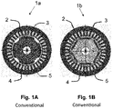
- a conventional electric motor 1a, 1b including without limitation an alternating current (AC) electric motor generally includes a rotor 2 and a stator 3.
- AC electric motor is a permanent magnet synchronous motor (PMSM)
- the rotor includes a plurality of permanent magnets 4 and the stator includes a coil winding 5.
- a PMSM motor can be separated into two main types, either a surface permanent magnet motor or an interior permanent magnet motor (IPM). More specifically, the permanent magnets 4 may be located by affixing them to the surface of the rotor 2 as shown in Fig. 1A or positioning them inside of the rotor 2 as shown in Fig. 1B .
- Both of these motor types generate a magnetic flux by the permanent magnets affixed to or inside of the rotor.
- the surface mounting of the magnets may weaken the mechanical strength of the assembly, thereby, limiting the safe mechanical speed at which the motor may operate.
- embedding the permanent magnets 4 into the rotor 2 makes the motor very mechanically sound and suitable for operating at very high speeds.
- the magnets 4 may be placed in multiple locations, however, such placement is done such that a symmetric pattern around a centerline (x) results.
- Each of the magnets may be inset as a large block or staggered as they come closer to the core. Another method is to have them imbedded in a spoke pattern.
- the number of magnets 4 may range from four to about 20, alternatively, 12 or less. Alternatively, the number of magnets 4 are represented by an even number, such as but not limited to four (see Fig. 1A ), six (see Fig. 1B ), eight, ten, or twelve.
- the permanent magnets may include, but not be limited to, neodymium-iron-boron (Nd-Fe-B), samarium-cobalt (Sm-Co), aluminum-nickel-cobalt (alnico), or ferrites (barium and strontium).
- Nd-Fe-B neodymium-iron-boron
- Sm-Co samarium-cobalt
- alnico aluminum-nickel-cobalt
- ferrites barium and strontium
- the stator windings 5 in the stator 3 of the permanent magnet synchronous motor (PMSM) 1a, 1b generates a rotating magnetic field that repels the magnetic fields exhibited by the permanent magnets 4, thereby creating the rotation of the rotor 2.
- the efficiency of a PMSM over other motors, such as an induction motor, is largely due to the rotor magnets creating an independent and permanent magnetic field, as additional current does not need to be induced to create the rotor field
- the permanent magnet synchronous motor (PMSM) 1c a plurality of rotors 2 configured to rotate within a stator 3 positioned to surround a portion of the rotors 2, the stator 3 and rotors 2 being aligned along a centerline (x).
- Each rotor 2 includes an asymmetric feature 7, such that during operation dynamic balance (shown in Figs. 2A & 2B ) results when the asymmetric feature 7 on each rotor 2 are aligned opposite one another perpendicular to the centerline (x) and static balance (shown in Figs. 3A & 3B ) results when the asymmetric feature 7 on each rotor 2 are aligned opposite one another parallel to the centerline (x).
- the asymmetric skewed rotors 2 may comprise a lamination stamping.
- This lamination stamping may include one or more symmetric features 8 in addition to the asymmetric feature 7.
- Any type of material known for use in lamination stamping for a motor assembly may be utilized, including but not limited to cobalt-iron alloys, nickel-iron alloys, silicon or electrical steel, iron-boron-silicon alloys, and lamination steel.
- the symmetric features 8 and asymmetric feature 7 may be orifices 6 that are formed in the rotors 2.
- the shape of these orifices 6 may include any type of geometric shape.
- Examples of possible geometric shapes include, but are not limited to, a circle, oval, square, rectangle, triangle, rhombus, trapezoid, hexagon, octagon, or parallelogram.
- the shape of the orifice 6 is a circle, rectangle, rhombus, triangle, or trapezoid. Any shape may be used for the orifice 6 may be utilized provided that such shape is optimized to not affect the magnetic circuit of the rotor.
- the orifice 6 of the asymmetric feature 7 may configured to be a portion of the orifice 6 of the symmetric features 8. For example, if the orifice 6 of the symmetric features 8 is a circle, the orifice 6 of the asymmetric feature 7 may be a half circle.
- the number of orifices 6 in the rotors 2 may range from four to about 20, alternatively, 12 or less. Alternatively, the number of orifices 6 are represented by an even number, such as but not limited to four, six (see Fig. 2A, 2B , 3A, 3B ), eight, ten, or twelve. The number of orifices 6 may reflect the number of magnets or magnetic poles incorporated with rotor in order to reduce the overall mass of the rotor.
- the other features of the rotor such as, for example, the type and number of permanent magnets, the material composition of the lamination stamping, and the design and configuration of the stator and the stator windings may be similar or the same as that found in conventional motors.
- an electric motor such as a PMSM, is formed using the rotors described above and further defined herein.
- This electric motor includes a stator positioned to at least partially surround the rotors. The stator and rotors being positioned, such that they are aligned along a centerline (x).
Landscapes
- Engineering & Computer Science (AREA)
- Power Engineering (AREA)
- Permanent Field Magnets Of Synchronous Machinery (AREA)
- Permanent Magnet Type Synchronous Machine (AREA)
Abstract
Description
- This disclosure relates generally to an asymmetrical skewed rotor configured for use in an electric motor, such as a permanent magnet synchronous motor (PMSM).
- The statements in this section merely provide background information related to the present disclosure and may not constitute prior art.
- The use of electric motors in many applications, such as high speed transportation, have transitioned from direct current (DC) drives to alternating current (AC) drives due to the evolution of power electronics, such as the development of improved inverters and use of vector control methodology. AC drives in comparison to DC drives provide greater reliability, high efficiency and superior power density along with lower maintenance requirements. AC drives typically associated with induction motors (IM) and permanent magnet synchronous motors (PMSM). The current trend seems to be transitioning to the preferential use PMSM technology based upon the potential for high efficiency and power density even though this technology is also linked to higher manufacturing and material costs.
- A PMSM is an AC synchronous motor whose field excitation is provided by permanent magnets. A PMSM may include magnet arrangements located on the surface or interior of the rotor with such magnets exhibiting radial or tangential magnetization. The performance of a PMSM with surface mounted magnets is similar to a synchronous motor having a cylindrical rotor in which the torque is entirely generated by the interaction between the flux of the rotor and the stator current. Although the PMSM offer many advantages, this technology also exhibits many disadvantages, such as the constant flux provided by the magnets and the high costs associated with the rare-earth magnets. In addition, the rotors associated with PMSM are known to exhibit cogging torque, as well as produce harmonics and vibrations during operation that require the use rotor skewing to reduce harmonics and axial counterweights to reduce vibration, which increase the size (e.g., length for use of end-mounted counterweights) and cost associated with the motor assembly.
- The present disclosure generally provides a plurality of asymmetric skewed rotors for use in an electric motor, as well as the electric motor formed therefrom. The rotors are configured to rotate within a stator positioned to surround a portion of the rotors with the stator and rotors being aligned along a centerline (x). Each of the rotors includes an asymmetric feature, such that during operation dynamic balance results when the asymmetric feature on each rotor are aligned opposite one another perpendicular to the centerline (x) and static balance results when the asymmetric feature on each rotor are aligned opposite one another parallel to the centerline (x).
- According to another aspect of the present disclosure, the asymmetric skewed rotors are incorporated into an electric motor, including without limitation, a permanent magnet synchronous motor (PMSM). The rotor representing the rotating mechanism that is at least partially surrounded by the stator.
- Further areas of applicability will become apparent from the description provided herein. It should be understood that the description and specific examples are intended for purposes of illustration only and are not intended to limit the scope of the present disclosure.
- In order that the disclosure may be well understood, there will now be described various forms thereof, given by way of example, reference being made to the accompanying drawings, in which:
-
Fig. 1A is a schematic representation of a conventional stator and rotor in a PMSM viewed along the centerline (x); -
Fig. 1 B is schematic representation of another conventional stator and rotor in a PMSM viewed along the centerline (x); -
Fig. 2A is a schematic representation of a stator and asymmetric skewed rotor according to the teachings of the present disclosure viewed along the centerline (x) that exhibits dynamic balance; -
Fig. 2B is a perspective view of the asymmetric skewed rotor inFig. 2A further exhibiting dynamic balance; -
Fig. 3A is a schematic representation of a stator and asymmetric skewed rotor according to the teachings of the present disclosure viewed along the centerline (x) that exhibits static balance; and -
Fig. 3B is a perspective view of asymmetric skewed rotor inFig. 3A further exhibiting static balance. - The drawings described herein are for illustration purposes only and are not intended to limit the scope of the present disclosure in any way. It should be understood that throughout the description, corresponding reference numerals indicate like or corresponding parts and features.
- Various embodiments described herein are focused towards an asymmetric skewed rotor configured for use as a rotating mechanism within an electric motor. The following description is merely exemplary in nature and is not intended to limit the present disclosure, application, or uses. For example, the asymmetric rotor elements made and used according to the teachings contained herein are described throughout the present disclosure in conjunction with a permanent magnet synchronous motor (PMSM) in order to more fully illustrate the construction and the use thereof. The incorporation and use of such rotor elements in any machinery, industrial equipment, or other apparatus that requires an electric motor, such as without limitation a PMSM, a servomotor, or the like, are contemplated not to exceed the scope of the present disclosure.
- The present disclosure generally provides asymmetric skewed rotors for use as part of the rotating mechanism in an electric motor, as well as an electric motor that includes such rotors. A rotating mechanism of a motor must be balanced in order to achieve noise, vibration and performance targets. The use of asymmetric skewed rotors as described above and further defined herein achieves these goals without the need to add external counterweights to the design, thereby reducing overall cost and axial packaging space. When desirable, supplementary counterweights may still be used but the size of such weights can be minimized.
- Referring to
Figures 1A and 1B , a conventionalelectric motor rotor 2 and astator 3. When the AC electric motor is a permanent magnet synchronous motor (PMSM), the rotor includes a plurality ofpermanent magnets 4 and the stator includes a coil winding 5. A PMSM motor can be separated into two main types, either a surface permanent magnet motor or an interior permanent magnet motor (IPM). More specifically, thepermanent magnets 4 may be located by affixing them to the surface of therotor 2 as shown inFig. 1A or positioning them inside of therotor 2 as shown inFig. 1B . Both of these motor types generate a magnetic flux by the permanent magnets affixed to or inside of the rotor. The surface mounting of the magnets may weaken the mechanical strength of the assembly, thereby, limiting the safe mechanical speed at which the motor may operate. On the other hand, embedding thepermanent magnets 4 into therotor 2 makes the motor very mechanically sound and suitable for operating at very high speeds. - Still referring to
Fig. 1A and Fig. 1B , themagnets 4 may be placed in multiple locations, however, such placement is done such that a symmetric pattern around a centerline (x) results. Each of the magnets may be inset as a large block or staggered as they come closer to the core. Another method is to have them imbedded in a spoke pattern. The number ofmagnets 4 may range from four to about 20, alternatively, 12 or less. Alternatively, the number ofmagnets 4 are represented by an even number, such as but not limited to four (seeFig. 1A ), six (seeFig. 1B ), eight, ten, or twelve. The permanent magnets may include, but not be limited to, neodymium-iron-boron (Nd-Fe-B), samarium-cobalt (Sm-Co), aluminum-nickel-cobalt (alnico), or ferrites (barium and strontium). - The
stator windings 5 in thestator 3 of the permanent magnet synchronous motor (PMSM) 1a, 1b generates a rotating magnetic field that repels the magnetic fields exhibited by thepermanent magnets 4, thereby creating the rotation of therotor 2. The efficiency of a PMSM over other motors, such as an induction motor, is largely due to the rotor magnets creating an independent and permanent magnetic field, as additional current does not need to be induced to create the rotor field - Referring now to
Fig. 2A, 2B ,3A, and 3B , the permanent magnet synchronous motor (PMSM) 1c according to one aspect of the present disclosure, a plurality ofrotors 2 configured to rotate within astator 3 positioned to surround a portion of therotors 2, thestator 3 androtors 2 being aligned along a centerline (x). Eachrotor 2 includes anasymmetric feature 7, such that during operation dynamic balance (shown inFigs. 2A & 2B ) results when theasymmetric feature 7 on eachrotor 2 are aligned opposite one another perpendicular to the centerline (x) and static balance (shown inFigs. 3A & 3B ) results when theasymmetric feature 7 on eachrotor 2 are aligned opposite one another parallel to the centerline (x). - The asymmetric
skewed rotors 2 may comprise a lamination stamping. This lamination stamping may include one or moresymmetric features 8 in addition to theasymmetric feature 7. Any type of material known for use in lamination stamping for a motor assembly may be utilized, including but not limited to cobalt-iron alloys, nickel-iron alloys, silicon or electrical steel, iron-boron-silicon alloys, and lamination steel. Still referring to Fig.'s 2A, 2B, 3A, and 3B, thesymmetric features 8 andasymmetric feature 7 may beorifices 6 that are formed in therotors 2. The shape of theseorifices 6 may include any type of geometric shape. Examples of possible geometric shapes include, but are not limited to, a circle, oval, square, rectangle, triangle, rhombus, trapezoid, hexagon, octagon, or parallelogram. Alternatively, the shape of theorifice 6 is a circle, rectangle, rhombus, triangle, or trapezoid. Any shape may be used for theorifice 6 may be utilized provided that such shape is optimized to not affect the magnetic circuit of the rotor. Theorifice 6 of theasymmetric feature 7 may configured to be a portion of theorifice 6 of the symmetric features 8. For example, if theorifice 6 of thesymmetric features 8 is a circle, theorifice 6 of theasymmetric feature 7 may be a half circle. - The number of
orifices 6 in therotors 2 may range from four to about 20, alternatively, 12 or less. Alternatively, the number oforifices 6 are represented by an even number, such as but not limited to four, six (seeFig. 2A, 2B ,3A, 3B ), eight, ten, or twelve. The number oforifices 6 may reflect the number of magnets or magnetic poles incorporated with rotor in order to reduce the overall mass of the rotor. The other features of the rotor, such as, for example, the type and number of permanent magnets, the material composition of the lamination stamping, and the design and configuration of the stator and the stator windings may be similar or the same as that found in conventional motors. - According to another aspect of the present disclosure, an electric motor, such as a PMSM, is formed using the rotors described above and further defined herein. This electric motor includes a stator positioned to at least partially surround the rotors. The stator and rotors being positioned, such that they are aligned along a centerline (x).
- Within this specification, embodiments have been described in a way which enables a clear and concise specification to be written, but it is intended and will be appreciated that embodiments may be variously combined or separated without parting from the invention. For example, it will be appreciated that all preferred features described herein are applicable to all aspects of the invention described herein.
- The foregoing description of various forms of the invention has been presented for purposes of illustration and description. It is not intended to be exhaustive or to limit the invention to the precise forms disclosed. Numerous modifications or variations are possible in light of the above teachings. The forms discussed were chosen and described to provide the best illustration of the principles of the invention and its practical application to thereby enable one of ordinary skill in the art to utilize the invention in various forms and with various modifications as are suited to the particular use contemplated. All such modifications and variations are within the scope of the invention as determined by the appended claims when interpreted in accordance with the breadth to which they are fairly, legally, and equitably entitled.
Claims (20)
- A motor having a rotating mechanism, the rotating mechanism comprising a stator that surrounds a portion of a plurality of rotors, the stator and rotors being aligned along a centerline (x);
wherein each rotor includes an asymmetric feature, such that during operation dynamic balance results when the asymmetric feature on each rotor are aligned opposite one another perpendicular to the centerline (x) and static balance results when the asymmetric feature on each rotor are aligned opposite one another parallel to the centerline (x). - The motor according to claim 1, wherein the motor is an alternating current (AC) motor.
- The motor according to claim 2, wherein the AC motor is a permanent magnet synchronous motor (PMSM).
- The motor according to claim 3, wherein the PMSM includes a plurality of permanent magnets arranged on the surface of the rotors or internally located within the body of the rotor.
- The motor according to claim 4, wherein each of the permanent magnets is independently selected as neodymium-iron-boron (Nd-Fe-B), samarium-cobalt (Sm-Co), aluminum-nickel-cobalt (alnico), or ferrites (barium and strontium).
- The motor according to claim 1, wherein each rotor comprises a lamination stamping comprising one or more symmetric features in addition to the asymmetric feature.
- The motor according to claim 6, wherein the one or more symmetric features and asymmetric feature are orifices formed in the rotor.
- The motor according to claim 7, wherein the orifices are shaped such that they are circular, oval, square, rectangular, triangular, rhombus, trapezoid, hexagon, octagon, or parallelogram.
- The motor according to claim 7, wherein the orifice of the asymmetric feature is shaped differently than the orifice of the symmetric features.
- The motor according to claim 9, wherein the orifice of the asymmetric feature represents a portion of the orifice of the symmetric features.
- A plurality of rotors for use in a motor, the rotors configured to rotate within a stator positioned to surround a portion of the rotors, the stator and rotors being aligned along a centerline (x);
wherein each rotor includes an asymmetric feature, such that during operation dynamic balance results when the asymmetric feature on each rotor are aligned opposite one another perpendicular to the centerline (x) and static balance results when the asymmetric feature on each rotor are aligned opposite one another parallel to the centerline (x). - The rotor according to claim 11, wherein the motor is an alternating current (AC) motor.
- The rotor according to claim 12, wherein the AC motor is a permanent magnet synchronous motor (PMSM).
- The rotor according to claim 13, wherein the PMSM includes a plurality of permanent magnets arranged on the surface of the rotors or internally located within the body of the rotor.
- The rotor according to claim 14, wherein each of the permanent magnets is independently selected as neodymium-iron-boron (Nd-Fe-B), samarium-cobalt (Sm-Co), aluminum-nickel-cobalt (alnico), or ferrites (barium and strontium).
- The rotor according to claim 11, wherein each rotor comprises a lamination stamping comprising one or more symmetric features in addition to the asymmetric feature.
- The rotor according to claim 16, wherein the one or more symmetric features and asymmetric feature are orifices formed in the rotor.
- The rotor according to claim 17, wherein the orifices are shaped such that they are circular, oval, square, rectangular, triangular, rhombus, trapezoid, hexagon, octagon, or parallelogram.
- The rotor according to claim 17, wherein the orifice of the asymmetric feature is shaped differently than the orifice of the symmetric features.
- The rotor according to claim 19, wherein the orifice of the asymmetric feature represents a portion of the orifice of the symmetric features.
Applications Claiming Priority (1)
| Application Number | Priority Date | Filing Date | Title |
|---|---|---|---|
| US17/151,823 US12051949B2 (en) | 2021-01-19 | 2021-01-19 | Asymmetrical skewed rotor |
Publications (1)
| Publication Number | Publication Date |
|---|---|
| EP4030599A1 true EP4030599A1 (en) | 2022-07-20 |
Family
ID=78820589
Family Applications (1)
| Application Number | Title | Priority Date | Filing Date |
|---|---|---|---|
| EP21211611.5A Pending EP4030599A1 (en) | 2021-01-19 | 2021-12-01 | Asymmetrical skewed rotor |
Country Status (4)
| Country | Link |
|---|---|
| US (1) | US12051949B2 (en) |
| EP (1) | EP4030599A1 (en) |
| JP (1) | JP2022111063A (en) |
| CN (1) | CN114825705B (en) |
Citations (2)
| Publication number | Priority date | Publication date | Assignee | Title |
|---|---|---|---|---|
| WO2020043966A1 (en) * | 2018-08-28 | 2020-03-05 | Psa Automobiles Sa | Method for balancing an electric motor rotor with machining of the lamination |
| CN111313640A (en) * | 2019-11-27 | 2020-06-19 | 珠海格力节能环保制冷技术研究中心有限公司 | Rotor assembly and permanent magnet motor having the same |
Family Cites Families (32)
| Publication number | Priority date | Publication date | Assignee | Title |
|---|---|---|---|---|
| DE694327C (en) | 1938-01-19 | 1940-07-30 | Fritz Tellert | Single-phase or multi-phase machine with square frame plates |
| US2830209A (en) | 1955-01-03 | 1958-04-08 | Licentia Gmbh | Lamination for stacks in asynchronous machines |
| GB887047A (en) | 1958-11-18 | 1962-01-17 | Friedrich Tellert | Improvements in or relating to dynamo electric machines |
| GB1124015A (en) | 1964-12-15 | 1968-08-14 | Ass Elect Ind | Improved dynamo-electric machines |
| DE1488657A1 (en) | 1965-03-13 | 1969-06-12 | Siemens Ag | Grooved sheets for electrical machines with axially running cooling ducts in the yoke |
| US3783318A (en) | 1972-10-06 | 1974-01-01 | Marathon Electric Mfg | Laminated stator core for dynamoelectric machines |
| JP3676242B2 (en) * | 2001-01-30 | 2005-07-27 | 三洋電機株式会社 | Induction synchronous motor |
| JP2003219616A (en) * | 2002-01-23 | 2003-07-31 | Toyota Industries Corp | Electric motor for electric compressor, method for adjusting rotor balance thereof, and electric compressor |
| DE10355267A1 (en) | 2003-11-26 | 2005-06-30 | Siemens Ag | Electric machine |
| DE102005005602A1 (en) | 2005-02-07 | 2006-08-24 | Siemens Ag | Electric machine with grooves |
| JP2007135379A (en) * | 2005-11-14 | 2007-05-31 | Mitsubishi Electric Corp | Magnet generator |
| KR101092321B1 (en) | 2005-12-21 | 2011-12-09 | 주식회사 동서전자 | Rotor of a line start permanent magnet synchronous motor |
| JP4969216B2 (en) * | 2006-11-17 | 2012-07-04 | 日立アプライアンス株式会社 | Permanent magnet synchronous motor and compressor |
| CN101267130B (en) | 2007-03-16 | 2013-03-13 | 德昌电机股份有限公司 | Armature overlapping slice |
| EP2112747B1 (en) | 2008-04-24 | 2014-01-22 | Magneti Marelli S.p.A. | Electrical machine and method for manufacturing the same |
| GB2468718A (en) | 2009-03-20 | 2010-09-22 | Control Tech Dynamics Ltd | Securing permanent magnets to a laminated rotor |
| JP2012050253A (en) * | 2010-08-27 | 2012-03-08 | Nippon Densan Corp | Rotary electric machine |
| DE102010041599A1 (en) * | 2010-09-29 | 2012-03-29 | Robert Bosch Gmbh | Balanced rotor for a rotary machine and method for balancing a rotor |
| CN102593977B (en) | 2011-01-04 | 2015-03-11 | 思科普有限责任公司 | Single-phase alternating current motor |
| DE102011083577A1 (en) | 2011-09-28 | 2013-03-28 | Siemens Aktiengesellschaft | Electric machine with stator with variable slot spacing |
| EP2578872B1 (en) | 2011-10-04 | 2018-01-03 | Siemens Aktiengesellschaft | Generator |
| JP2013179765A (en) * | 2012-02-28 | 2013-09-09 | Daikin Ind Ltd | Rotating electric machine |
| CN104247213B (en) * | 2012-04-16 | 2018-10-12 | 奥的斯电梯公司 | Magneto |
| US20180262081A1 (en) * | 2017-03-10 | 2018-09-13 | Regal Beloit America, Inc. | Electric motor including stator assembly and method of assembly thereof |
| FR3069730B1 (en) | 2017-07-31 | 2021-08-20 | Leroy Somer Moteurs | INJECTED CAGE ROTOR |
| DE102017213890B4 (en) | 2017-08-09 | 2025-12-24 | Schaeffler Technologies AG & Co. KG | Method for fixing a permanent magnet in a rotor lamination stack for an electric machine |
| DE102017214508A1 (en) | 2017-08-21 | 2019-02-21 | Robert Bosch Gmbh | Rotor for an electric machine, in particular for an electric motor |
| US10833543B2 (en) | 2017-10-02 | 2020-11-10 | Ge Aviation Systems Llc | Stator assembly |
| CN107872107B (en) | 2017-11-06 | 2020-03-03 | 珠海格力节能环保制冷技术研究中心有限公司 | Stator punching sheet, stator and motor |
| KR102611335B1 (en) * | 2019-01-02 | 2023-12-08 | 엘지마그나 이파워트레인 주식회사 | Shaft structure of motor |
| DE102019207879A1 (en) * | 2019-05-29 | 2020-12-03 | Robert Bosch Gmbh | Rotor of an electrical machine |
| US11223262B1 (en) * | 2020-10-20 | 2022-01-11 | Tempel Steel Company | Rotating punch with a relief feature for forming IPM motor rotor |
-
2021
- 2021-01-19 US US17/151,823 patent/US12051949B2/en active Active
- 2021-12-01 EP EP21211611.5A patent/EP4030599A1/en active Pending
- 2021-12-06 JP JP2021197553A patent/JP2022111063A/en active Pending
- 2021-12-23 CN CN202111590716.8A patent/CN114825705B/en active Active
Patent Citations (2)
| Publication number | Priority date | Publication date | Assignee | Title |
|---|---|---|---|---|
| WO2020043966A1 (en) * | 2018-08-28 | 2020-03-05 | Psa Automobiles Sa | Method for balancing an electric motor rotor with machining of the lamination |
| CN111313640A (en) * | 2019-11-27 | 2020-06-19 | 珠海格力节能环保制冷技术研究中心有限公司 | Rotor assembly and permanent magnet motor having the same |
Also Published As
| Publication number | Publication date |
|---|---|
| CN114825705A (en) | 2022-07-29 |
| US12051949B2 (en) | 2024-07-30 |
| CN114825705B (en) | 2025-09-12 |
| JP2022111063A (en) | 2022-07-29 |
| US20220231585A1 (en) | 2022-07-21 |
Similar Documents
| Publication | Publication Date | Title |
|---|---|---|
| JP2695332B2 (en) | Permanent magnet field type rotor | |
| JP5268711B2 (en) | Electric motor and compressor, air conditioner and vacuum cleaner | |
| JP5851365B2 (en) | Rotating electric machine | |
| JP5610726B2 (en) | Electric motor | |
| JP2006509483A (en) | Electric machines, especially brushless synchronous motors | |
| EP4187759A1 (en) | Electric motor | |
| JPWO2022019074A5 (en) | ||
| CN111106685A (en) | Permanent magnet motor based on special-shaped magnetic pole array | |
| WO2025002463A1 (en) | Rotor structure and motor | |
| JP2018519782A (en) | Permanent magnet motor | |
| US20130169094A1 (en) | Rotor Lamination Structure For Permanent Magnet Machine | |
| JP3489215B2 (en) | Permanent magnet synchronous motor | |
| JP2025058776A (en) | Surface magnet type synchronous machine, rotor thereof and manufacturing method thereof | |
| KR101918069B1 (en) | Motor having permanent magnet division module and manufacturing method thereof | |
| US12051949B2 (en) | Asymmetrical skewed rotor | |
| US20240221987A1 (en) | Apparatus for manufacturing rotor | |
| WO2021079508A1 (en) | Electric motor | |
| KR102619942B1 (en) | Afpm motor with rfpm motor structure applied | |
| US11705766B2 (en) | Electric motor having permanent magnet rotor and stator | |
| KR101260689B1 (en) | Rotor and synchronous motor having the rotor | |
| KR102120361B1 (en) | A rotor having a conductor bar of a different length and a synchronous motor comprising the same | |
| KR20230001701A (en) | Motor | |
| KR20030057835A (en) | Axial Core Type Brushless DC Motor | |
| JP2021122163A (en) | Rotating machine | |
| JP7850892B2 (en) | Rotor and motor |
Legal Events
| Date | Code | Title | Description |
|---|---|---|---|
| PUAI | Public reference made under article 153(3) epc to a published international application that has entered the european phase |
Free format text: ORIGINAL CODE: 0009012 |
|
| STAA | Information on the status of an ep patent application or granted ep patent |
Free format text: STATUS: THE APPLICATION HAS BEEN PUBLISHED |
|
| AK | Designated contracting states |
Kind code of ref document: A1 Designated state(s): AL AT BE BG CH CY CZ DE DK EE ES FI FR GB GR HR HU IE IS IT LI LT LU LV MC MK MT NL NO PL PT RO RS SE SI SK SM TR |
|
| STAA | Information on the status of an ep patent application or granted ep patent |
Free format text: STATUS: REQUEST FOR EXAMINATION WAS MADE |
|
| 17P | Request for examination filed |
Effective date: 20221123 |
|
| RBV | Designated contracting states (corrected) |
Designated state(s): AL AT BE BG CH CY CZ DE DK EE ES FI FR GB GR HR HU IE IS IT LI LT LU LV MC MK MT NL NO PL PT RO RS SE SI SK SM TR |
|
| STAA | Information on the status of an ep patent application or granted ep patent |
Free format text: STATUS: EXAMINATION IS IN PROGRESS |
|
| 17Q | First examination report despatched |
Effective date: 20250526 |