EP4030595A1 - Machine dynamoélectrique à refroidissement du système de bague collectrice - Google Patents
Machine dynamoélectrique à refroidissement du système de bague collectrice Download PDFInfo
- Publication number
- EP4030595A1 EP4030595A1 EP21152087.9A EP21152087A EP4030595A1 EP 4030595 A1 EP4030595 A1 EP 4030595A1 EP 21152087 A EP21152087 A EP 21152087A EP 4030595 A1 EP4030595 A1 EP 4030595A1
- Authority
- EP
- European Patent Office
- Prior art keywords
- slip ring
- shaft
- ring body
- cavity
- slip
- Prior art date
- Legal status (The legal status is an assumption and is not a legal conclusion. Google has not performed a legal analysis and makes no representation as to the accuracy of the status listed.)
- Withdrawn
Links
- 238000001816 cooling Methods 0.000 title description 47
- 238000004804 winding Methods 0.000 claims abstract description 17
- 230000005540 biological transmission Effects 0.000 claims abstract description 5
- 239000002826 coolant Substances 0.000 claims description 4
- 230000002093 peripheral effect Effects 0.000 claims description 3
- 230000004323 axial length Effects 0.000 claims description 2
- 239000003570 air Substances 0.000 description 34
- 239000004020 conductor Substances 0.000 description 18
- 230000005284 excitation Effects 0.000 description 3
- 238000000034 method Methods 0.000 description 2
- 238000013021 overheating Methods 0.000 description 2
- 238000009423 ventilation Methods 0.000 description 2
- OKTJSMMVPCPJKN-UHFFFAOYSA-N Carbon Chemical compound [C] OKTJSMMVPCPJKN-UHFFFAOYSA-N 0.000 description 1
- 239000012080 ambient air Substances 0.000 description 1
- 230000015572 biosynthetic process Effects 0.000 description 1
- 229910052799 carbon Inorganic materials 0.000 description 1
- 238000010276 construction Methods 0.000 description 1
- 230000000694 effects Effects 0.000 description 1
- 238000005755 formation reaction Methods 0.000 description 1
- 239000011796 hollow space material Substances 0.000 description 1
- 238000009434 installation Methods 0.000 description 1
- 230000000284 resting effect Effects 0.000 description 1
- 230000000630 rising effect Effects 0.000 description 1
- 230000003068 static effect Effects 0.000 description 1
- 239000013589 supplement Substances 0.000 description 1
Images


Classifications
-
- H—ELECTRICITY
- H02—GENERATION; CONVERSION OR DISTRIBUTION OF ELECTRIC POWER
- H02K—DYNAMO-ELECTRIC MACHINES
- H02K9/00—Arrangements for cooling or ventilating
- H02K9/28—Cooling of commutators, slip-rings or brushes e.g. by ventilating
-
- H—ELECTRICITY
- H02—GENERATION; CONVERSION OR DISTRIBUTION OF ELECTRIC POWER
- H02K—DYNAMO-ELECTRIC MACHINES
- H02K13/00—Structural associations of current collectors with motors or generators, e.g. brush mounting plates or connections to windings; Disposition of current collectors in motors or generators; Arrangements for improving commutation
- H02K13/003—Structural associations of slip-rings
-
- H—ELECTRICITY
- H02—GENERATION; CONVERSION OR DISTRIBUTION OF ELECTRIC POWER
- H02K—DYNAMO-ELECTRIC MACHINES
- H02K17/00—Asynchronous induction motors; Asynchronous induction generators
- H02K17/02—Asynchronous induction motors
- H02K17/22—Asynchronous induction motors having rotors with windings connected to slip-rings
- H02K17/24—Asynchronous induction motors having rotors with windings connected to slip-rings in which both stator and rotor are fed with AC
-
- H—ELECTRICITY
- H02—GENERATION; CONVERSION OR DISTRIBUTION OF ELECTRIC POWER
- H02K—DYNAMO-ELECTRIC MACHINES
- H02K17/00—Asynchronous induction motors; Asynchronous induction generators
- H02K17/42—Asynchronous induction generators
-
- H—ELECTRICITY
- H02—GENERATION; CONVERSION OR DISTRIBUTION OF ELECTRIC POWER
- H02K—DYNAMO-ELECTRIC MACHINES
- H02K9/00—Arrangements for cooling or ventilating
- H02K9/02—Arrangements for cooling or ventilating by ambient air flowing through the machine
- H02K9/04—Arrangements for cooling or ventilating by ambient air flowing through the machine having means for generating a flow of cooling medium
-
- F—MECHANICAL ENGINEERING; LIGHTING; HEATING; WEAPONS; BLASTING
- F03—MACHINES OR ENGINES FOR LIQUIDS; WIND, SPRING, OR WEIGHT MOTORS; PRODUCING MECHANICAL POWER OR A REACTIVE PROPULSIVE THRUST, NOT OTHERWISE PROVIDED FOR
- F03D—WIND MOTORS
- F03D9/00—Adaptations of wind motors for special use; Combinations of wind motors with apparatus driven thereby; Wind motors specially adapted for installation in particular locations
- F03D9/20—Wind motors characterised by the driven apparatus
- F03D9/25—Wind motors characterised by the driven apparatus the apparatus being an electrical generator
-
- H—ELECTRICITY
- H01—ELECTRIC ELEMENTS
- H01R—ELECTRICALLY-CONDUCTIVE CONNECTIONS; STRUCTURAL ASSOCIATIONS OF A PLURALITY OF MUTUALLY-INSULATED ELECTRICAL CONNECTING ELEMENTS; COUPLING DEVICES; CURRENT COLLECTORS
- H01R39/00—Rotary current collectors, distributors or interrupters
- H01R39/02—Details for dynamo electric machines
- H01R39/08—Slip-rings
-
- H—ELECTRICITY
- H02—GENERATION; CONVERSION OR DISTRIBUTION OF ELECTRIC POWER
- H02K—DYNAMO-ELECTRIC MACHINES
- H02K7/00—Arrangements for handling mechanical energy structurally associated with dynamo-electric machines, e.g. structural association with mechanical driving motors or auxiliary dynamo-electric machines
- H02K7/18—Structural association of electric generators with mechanical driving motors, e.g. with turbines
- H02K7/1807—Rotary generators
- H02K7/1823—Rotary generators structurally associated with turbines or similar engines
- H02K7/183—Rotary generators structurally associated with turbines or similar engines wherein the turbine is a wind turbine
-
- Y—GENERAL TAGGING OF NEW TECHNOLOGICAL DEVELOPMENTS; GENERAL TAGGING OF CROSS-SECTIONAL TECHNOLOGIES SPANNING OVER SEVERAL SECTIONS OF THE IPC; TECHNICAL SUBJECTS COVERED BY FORMER USPC CROSS-REFERENCE ART COLLECTIONS [XRACs] AND DIGESTS
- Y02—TECHNOLOGIES OR APPLICATIONS FOR MITIGATION OR ADAPTATION AGAINST CLIMATE CHANGE
- Y02E—REDUCTION OF GREENHOUSE GAS [GHG] EMISSIONS, RELATED TO ENERGY GENERATION, TRANSMISSION OR DISTRIBUTION
- Y02E10/00—Energy generation through renewable energy sources
- Y02E10/70—Wind energy
- Y02E10/72—Wind turbines with rotation axis in wind direction
Definitions
- the invention relates to a dynamoelectric machine, in particular a double-fed asynchronous machine with a slip ring system, as a generator for a wind power plant.
- a three-phase system is impressed in the rotor.
- a slip ring system is used for power transmission. With such a slip ring system, the electrical three-phase current system is transmitted to slip rings and thus to the rotating part of the machine - the rotor - via stationary brushes.
- the three-phase system is routed from the slip rings via appropriate conductors to the rotor winding of the rotor.
- Such a slip ring system for a dynamoelectric machine in particular a double-fed asynchronous machine, is used, for example, in wind power plants.
- the electrical machines or the generators and their components are made more and more compact. This leads to the slip ring components being thermally stressed more and more with the size remaining the same, since the temperatures, in particular of slip rings, slip ring brushes and brush holders, rise sharply.
- a fan in the slip ring housing ensures air circulation by directing air from the outside (interior of the nacelle) through the entire slip ring system and thus providing the necessary cooling for the system.
- the object of the invention is therefore to improve a slip ring system of a dynamoelectric machine, in particular a double-fed asynchronous machine, above all a wind turbine.
- an internally cooled slip ring body can now be achieved via the axial cavity that is open on both sides create. Not only can the slip ring body be cooled radially from the inside, but the cavity also contributes, among other things, to the cooling of the shaft in this area of the shaft.
- the cavity thus forms a heat sink there during operation of the slip ring system and thus of the dynamoelectric machine.
- the shaft is hollow in a preferred embodiment, at least in the axial area of the slip ring body, in order to conduct the excitation power from the slip ring system into the rotor or runner via electrical conductors, the conductors running there can also be cooled by the coolable shaft section.
- the conductors are designed as flexible conductors, for example stranded conductors, or as rigid conductors in the form of a rail system and are used to excite a winding system of the rotor or runner.
- the slip ring body and additionally the following components can now be cooled.
- the shaft in particular the axial shaft section and, in the case of a hollow shaft, the stranded conductors running, in particular arranged, in the shaft.
- the slip ring body, the shaft and the conductors for the excitation power, which run in the shaft or the axial hollow shaft section can now be cooled in a targeted manner, i.e. the heat load on these components can be absorbed by a coolant, in particular a cooling air flow.
- the slip rings have a ring shape, ie they are hollow on the inside and have a defined ring width. They are used to transfer electrical energy from a static supply system to a rotating part (rotor) of a double-fed asynchronous machine.
- the transmission usually takes place by means of (sanding) brushes made of carbon, which are guided along a surface of the slip rings and thereby electrical energy is transferred to the slip rings, which then makes them available to the rotor winding system via electrical conductors.
- the individual slip rings of each electrical phase are each surrounded by insulating segments in the axial direction, which electrically insulate the slip ring bodies from one another.
- a ground ring is also insulated from the adjacent slip ring.
- a support ring is arranged at the other axial end of the slip ring body, which is connected to the individual slip rings and the insulating bodies by means of connecting means (e.g. bolts) in order to provide the slip ring body with the necessary mechanical stability.
- the slip ring body has three slip rings, a grounding ring that is electrically connected to the support structure, and an insulating sleeve to insulate the slip rings from the grounding ring and/or from one another.
- the insulating sleeve is arranged on the respective section of the support structure.
- a different electrical phase of the three-phase system is regularly routed via each slip ring.
- the grounding ring is connected to the grounding system, for example the dynamoelectric machine and/or an overall system.
- the cavity is designed as a peripheral recess, so that the slip ring body is non-rotatably connected to the shaft at least on two circumferentially spaced end sections or delimiting elements, thus creating the cavity that represents a cooling section.
- end sections or delimiting elements can be implemented in particular as rings or webs. They are part of the supporting structure and/or the shaft. So they are integral with one or the other part formed and form the cooling section by axially attaching the slip ring body to the shaft or hollow shaft.
- the end sections or delimiting elements in particular the rings or webs, there are axially extending recesses or bores which enable the cooling described above.
- these recesses or substantially axially running bores are now provided on the circumference of the support structure and/or shaft in the region of the non-rotatable connection, for example a shrinkage.
- These recesses or essentially axially running bores are provided both on the bearing side (ie the side facing the rotor) and on the connection side (ie the side facing away from the rotor).
- the cooling takes place, for example, in such a way that cooling air is sucked in or pressed on the bearing side through further recesses on the grounding ring.
- This cooling air passes through the cooling section--that is, via these recesses or substantially axially running bores in the end sections--into the cavity, where it absorbs the heat load.
- the heated air is conveyed to the outside via openings in a slip ring housing via a fan, for example on the connection side. There, this heated air is re-cooled.
- the cooling mentioned above supplements an existing cooling circuit in which the brushes and slip ring surface are already cooled by radial fans. Due to the internally cooled slip ring body, there is a further cooling circuit for the shaft, the conductors running in the shaft, and the slip ring body.
- This cooling circuit significantly reduces the temperatures of the stranded conductors or a busbar system in the shaft and the slip ring body due to the additionally created cooling circuit. This means higher performance with the same components in the same installation space of the slip ring system feasible, which has an extremely cost-saving effect.
- This construction means that cool ambient air is guided through the highly heated area between the shaft and the slip ring body, ie the cavity, and the conductors, in particular stranded conductors, in the shaft or the hollow shaft section are therefore also cooled.
- the heated air is discharged through openings on the grounding ring and through recesses or bores on the bearing and connection sides around the entire circumference of the slip ring body in the end sections.
- the cooler air is guided through these openings and the recesses or bores into the cavity between the shaft and the slip ring body.
- the air flow to be generated is supported by a dedicated fan or an existing fan in the slip ring housing.
- the air is thus routed directly to the heated points of the slip ring body, the shaft and indirectly the stranded wire.
- the areas between shaft, slip ring body and the strands remain in the permissible temperature range and overheating of the slip ring system is thus prevented.
- a slip ring body with this cooling concept can therefore be used for significantly higher performance than before.
- the cavity can be created radially inside the slip ring body by the shaft having a diameter reduction over a predetermined axial length and/or the slip ring body having a diameter increase in the region of the desired cavity.
- the slip ring body is non-rotatably connected to the shaft at least via two circumferentially spaced delimitation elements, such as rings or webs.
- the delimiting elements, ie the rings or webs are part of the supporting structure of the slip ring body and/or the shaft. They are thus formed in one piece with one or the other part and form the cooling section by axially slipping the slip ring body onto the shaft or hollow shaft.
- the delimiting elements for example the rings or webs, there are axially extending recesses which enable the cooling described above.
- the cavity can have meandering or labyrinth-like structures which extend the dwell time of a cooling air flow in the cavity and thus allow the cooling air flow to absorb a higher thermal load there.
- the structures can be separate, insertable elements, or they can already be incorporated into the slip ring body and/or the shaft.
- the temperatures of the electrical machine are also significantly reduced by the cooling of the slip ring body that rests axially on the electrical machine.
- the resulting lower temperature of the slip ring system allows smaller sizes of the slip ring bodies or the slip ring system.
- the slip ring system can be loaded with more brushes per phase, which would not be possible without such cooling.
- higher performance levels than before can be achieved with the same overall volume of the slip ring system.
- slip rings for example grooves in the running surfaces, which allow radial airflow, as well as axial bores in the slip ring which allow axial cooling air.
- the insulating segments between the slip rings can have a fan-like design in order to create turbulence in the slip ring housing when the slip ring body rotates.
- the brush device can also be additionally cooled by providing the brush shafts with surface-enlarging measures. Targeted air flows using external fans and/or guide devices also contribute to cooling within the slip ring housing.
- the slip rings, their running surfaces, the brush temperatures, etc. remain within an operating temperature range and the operation of the dynamo-electric machine is protected against overheating.
- the invention can also be used in motors.
- the cooling circuits can be designed as closed cooling circuits or open cooling circuits.
- the cooling medium e.g. air
- the cooling medium is selectively re-cooled, for example by a heat exchanger.
- the cooling medium e.g. air from the environment, is used and released back into the environment when heated.
- FIG 1 shows a basic longitudinal section of a dynamoelectric machine 24 in a housing 29.
- a stator 25 is inserted in the housing 29 and has a winding system 26 in slots of a laminated core of the stator 25, which are not shown in detail.
- the end faces of the stator 25 are formed by the winding system 26 overhangs.
- Spaced apart from the stator 25 by an air gap 43 is a rotatably mounted rotor 27 with a winding system 28 which also forms end windings on the end faces of the rotor 27 .
- the rotor 27 is supported on the housing 29 of the machine 24 via bearings 30 and end shields.
- a slip ring system 1 in the axial extension of the dynamoelectric machine 24 which is connected to the winding system 28 of the rotor 27 via supply lines 35 .
- the supply lines 35 preferably run in a hollow shaft section of the shaft 4.
- the slip ring system 1 has a slip ring body 2 and a brush unit 14 which are accommodated in a slip ring housing 17 .
- the slip ring body 2 has slip rings 3 arranged axially one behind the other, each of which is spaced axially from an insulating segment 7 .
- a grounding ring 6 is located on one end face of the slip ring body 2 and an insulating ring 5 is located on the other end face of the slip ring body 2.
- Contact bolts 8 protrude axially from this insulating ring 5, each of which makes electrical contact with the associated slip ring 3.
- the brush unit 14 is positioned in a slip ring housing 17 and has one or more brushes 15 for each electrical phase, ie for each slip ring 3 Slip ring 3 and the grounding ring 6 are assigned.
- the brushes 15 are each arranged in a brush holder 22, which also provides corresponding electrical contacting devices.
- the brushes 15 per slip ring 3 are arranged side by side and/or one behind the other.
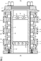
- FIG 2 1 shows a slip ring body 2 in a basic longitudinal section, the slip rings 3 being spaced apart axially one behind the other and from the respective insulating segments 7 .
- the slip rings 3 are arranged on an insulating sleeve 16 which is arranged on a support structure 41 or hub. This support structure 41 is at the same electrical potential as the grounding ring 6.
- Each of the slip rings 3 is electrically contacted with one or more contact bolts 8, so that the electrical energy provided on the running surface 40 of the respective slip ring 3 can be fed to the contact bolt 8 in order to from there to be guided via conductors, in particular stranded conductors, through the hollow shaft or hollow shaft section to the winding system 28 of the rotor 27 .
- the slip ring body 2 On its radially inner side facing the shaft 4, the slip ring body 2 has an axial section which is set back with respect to the end sections 12 delimiting it, ie has a larger inner radius. In these end sections 12 there are openings 21 which act as ventilation bores or vent bores. As soon as the slip ring body 2 is on a shaft 4 or hollow shaft, this comparatively larger inner radius creates a cavity 11 between the two end sections 12 of the support structure 41, i.e. the axial delimiting elements of the cavity 11, which can be designed as rings or webs.
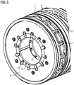
- FIG. 3 shows a partial perspective view of a slip ring body 2 from one end, more precisely from the machine side or bearing side 39.
- the grounding ring 6 can be seen on the end face of the slip ring body 2 and its spacing from a slip ring 3 by an insulating segment 7.
- the running surface 10 of a slip ring 3 can also be seen, on which grooves 9 are located, which also allow radial ventilation of the slip ring 3 .
- Openings 13 are provided on the grounding ring 6 and allow air to flow through the openings 21 in the end sections or delimiting elements into the cavity 11 which results between the shaft 4 and the slip ring body 2 .
- FIG 4 shows a perspective representation of the slip ring body 3 from its other front side, the connection side 40.
- Contact bolts 8 emerge axially from the insulating ring 5, with each electrical phase or each slip ring 3 being assigned two contact bolts 8 in this case.
- a sequence of insulating segments 7 and slip rings 3 follows axially. The axial series is terminated by the grounding ring 6.
- the running surfaces 10 of the individual slip rings 3 have grooves 9 which are radially continuous and thus allow further cooling of the slip ring 3 if necessary.
- these slip rings 3 have axial openings, which also contribute to the cooling of the slip rings 3 .
- the insulating segments 7 are designed like shovels at their radially outer edge, so that air turbulence occurs when the slip ring body 2 rotates.
- the slip ring body 2 has a central opening 31 into which a shaft 4, a shaft 4 with an axial hollow shaft section or a hollow shaft is inserted.
- This shaft 4 is non-rotatably connected to the slip ring body 2 .
- the winding system 28 of the rotor 27 is now electrically supplied via the contact bolts 8 and electrical supply lines 35 connected to them via a hollow shaft section of the shaft 4 or the hollow shaft.
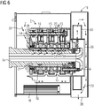
- FIG. 5 shows a slip ring system 1 in a longitudinal section, with a slip ring body 2 and a brush unit 14.
- the slip ring body 2 is non-rotatably positioned on the shaft 4 with the hollow shaft section or hollow shaft.
- Leads 35 in the form of stranded conductors are routed from the insulating ring 5 and the contact bolts 8 arranged there through the hollow shaft or hollow shaft section of the shaft 4 to the winding system 28 of the rotor 27 (not shown in detail in this figure).
- This supply line 35 is either exposed in the hollow shaft or is embedded in a type of thermally conductive paste in order to obtain good thermal contact with the shaft 4 .
- the cavity 11 now formed between the outer peripheral surface of the hollow shaft and the inner surface of the slip ring body 2 can now be cooled from the inside and the shaft via bores 21 in the end sections 12 resting on the hollow shaft section, which are in particular designed as webs 4 take place.
- the cooling takes place in particular by an air flow, which is arranged by a fan unit 19 on the connection side 40 .
- a fan 20 sucks or presses a flow of cooling air into the slip ring housing 17, which guides the flow of cooling air and directs it to the heat sources of the slip ring system 1 by appropriately designing the guide and guide devices.
- the fan 20 in the present case is responsible in particular for the cooling air 33 through the cavity 11 .
- air is sucked in from the environment, in the case of a wind generator from the nacelle, and discharged again via an air outlet 38 on the slip ring system 1 .
- FIG 6 shows the course of the cooling air flows 33 in an arrangement according to FIG figure 5 . It can be seen in particular that heat input 34 into the cooling air 33 guided through the cavity 11 occurs from the slip rings 3 and from the shaft 4 and thus also from the supply lines 35 (stranded conductors or rail system).
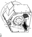
- FIG 7 shows a perspective view of the slip ring system 1 from the bearing side 39.
- the slip ring housing 17 is shown with its air inlets 18 and air outlets 38, which enable the slip ring system 1 to be cooled.
- the brush unit 14 is supported in the slip ring housing 17 .
- the slip ring body 2 with its slip rings 3 is positioned radially further inwards and on a shaft 4 or hollow shaft or hollow shaft section Cavity 11 can be performed.
- a fan unit 19 adjoins axially the slip ring housing 17 and controls the fan 20 and its distribution of the cooling air flows.
- the heated air is preferably sucked out of the cavity 11 and discharged through the fan cap 36 from the slip ring housing 17 to the outside.
- the contact pins 8 are also cooled in the process.
- the temperatures of the slip ring system 1 and of the entire electrical machine 24 can be significantly reduced. This means that smaller sizes of the slip ring system 1 are possible or higher performance levels can be achieved with the same size.
- an additional cooling of the slip ring system 1 is possible via the grooves 9 of the running surfaces 10, as well as the axial openings in the slip rings 3 and the insulating segments 7 designed like a fan.
- the formations of the insulating segment 7 or optionally a plurality of insulating segments 7 ideally form a fan which is provided for distributing a cooling air flow in the direction of the parts of the electrical machine 24 to be cooled.
- Such dynamo-electric machines 24 with a slip ring system 1 are designed in particular as double-fed asynchronous machines (ASM) that act as generators
- ASM asynchronous machines
- Wind turbines are preferably used in the power range between 0.5 and 8 MW.
- the wind turbines can be exhibited on-shore but also off-shore.
Landscapes
- Engineering & Computer Science (AREA)
- Power Engineering (AREA)
- Life Sciences & Earth Sciences (AREA)
- Sustainable Development (AREA)
- Sustainable Energy (AREA)
- Motor Or Generator Cooling System (AREA)
- Motor Or Generator Current Collectors (AREA)
Priority Applications (5)
| Application Number | Priority Date | Filing Date | Title |
|---|---|---|---|
| EP21152087.9A EP4030595A1 (fr) | 2021-01-18 | 2021-01-18 | Machine dynamoélectrique à refroidissement du système de bague collectrice |
| EP22701308.3A EP4278428A1 (fr) | 2021-01-18 | 2022-01-11 | Machine dynamo-électrique avec refroidissement du système à bagues collectrices |
| PCT/EP2022/050419 WO2022152685A1 (fr) | 2021-01-18 | 2022-01-11 | Machine dynamo-électrique avec refroidissement du système à bagues collectrices |
| CN202280010552.3A CN116783804A (zh) | 2021-01-18 | 2022-01-11 | 具有对于滑环系统的冷却的电动机器 |
| US18/272,751 US20240162794A1 (en) | 2021-01-18 | 2022-01-11 | Dynamoelectric machine having cooling of the slip ring system |
Applications Claiming Priority (1)
| Application Number | Priority Date | Filing Date | Title |
|---|---|---|---|
| EP21152087.9A EP4030595A1 (fr) | 2021-01-18 | 2021-01-18 | Machine dynamoélectrique à refroidissement du système de bague collectrice |
Publications (1)
| Publication Number | Publication Date |
|---|---|
| EP4030595A1 true EP4030595A1 (fr) | 2022-07-20 |
Family
ID=74187155
Family Applications (2)
| Application Number | Title | Priority Date | Filing Date |
|---|---|---|---|
| EP21152087.9A Withdrawn EP4030595A1 (fr) | 2021-01-18 | 2021-01-18 | Machine dynamoélectrique à refroidissement du système de bague collectrice |
| EP22701308.3A Pending EP4278428A1 (fr) | 2021-01-18 | 2022-01-11 | Machine dynamo-électrique avec refroidissement du système à bagues collectrices |
Family Applications After (1)
| Application Number | Title | Priority Date | Filing Date |
|---|---|---|---|
| EP22701308.3A Pending EP4278428A1 (fr) | 2021-01-18 | 2022-01-11 | Machine dynamo-électrique avec refroidissement du système à bagues collectrices |
Country Status (4)
| Country | Link |
|---|---|
| US (1) | US20240162794A1 (fr) |
| EP (2) | EP4030595A1 (fr) |
| CN (1) | CN116783804A (fr) |
| WO (1) | WO2022152685A1 (fr) |
Families Citing this family (1)
| Publication number | Priority date | Publication date | Assignee | Title |
|---|---|---|---|---|
| CN115064914B (zh) * | 2022-07-22 | 2022-11-22 | 海外远景(北京)科技有限公司 | 一种盘式风力发电变桨滑环 |
Citations (9)
| Publication number | Priority date | Publication date | Assignee | Title |
|---|---|---|---|---|
| DE504351C (de) * | 1927-05-29 | 1930-08-02 | Siemens Schuckertwerke Akt Ges | Anordnung zur Entfernung des Buerstenstaubes von den ungekapselten Schleifringen elektrischer Maschinen |
| DE918876C (de) * | 1942-03-07 | 1954-10-07 | Siemens Ag | Beluefteter Kollektor |
| JPS56162953A (en) * | 1980-05-19 | 1981-12-15 | Hitachi Ltd | Current collector for rotary electric machine |
| JPS593768U (ja) * | 1982-06-29 | 1984-01-11 | 富士電機株式会社 | 回転電機のスリツプリング |
| DE19807708A1 (de) * | 1998-02-24 | 1999-08-05 | Siemens Ag | Läufer und Verfahren zur Kühlung eines Schleifrings |
| EP2701286A2 (fr) * | 2012-08-23 | 2014-02-26 | Robert Bosch GmbH | Boîtier pour une machine électrique dotée d'un canal de refroidissement en forme de méandre et de géométries conductrices |
| EP2887509A1 (fr) * | 2013-12-20 | 2015-06-24 | Siemens Aktiengesellschaft | Dispositif de contact électrique pour une machine électrique |
| DE102013021745A1 (de) * | 2013-12-20 | 2015-06-25 | Sew-Eurodrive Gmbh & Co Kg | Umrichtermotor |
| EP3322047A1 (fr) | 2016-11-15 | 2018-05-16 | Siemens Aktiengesellschaft | Unité de bague collectrice comprenant un segment d'isolant de ventilateur |
-
2021
- 2021-01-18 EP EP21152087.9A patent/EP4030595A1/fr not_active Withdrawn
-
2022
- 2022-01-11 CN CN202280010552.3A patent/CN116783804A/zh active Pending
- 2022-01-11 US US18/272,751 patent/US20240162794A1/en active Pending
- 2022-01-11 WO PCT/EP2022/050419 patent/WO2022152685A1/fr active Application Filing
- 2022-01-11 EP EP22701308.3A patent/EP4278428A1/fr active Pending
Patent Citations (9)
| Publication number | Priority date | Publication date | Assignee | Title |
|---|---|---|---|---|
| DE504351C (de) * | 1927-05-29 | 1930-08-02 | Siemens Schuckertwerke Akt Ges | Anordnung zur Entfernung des Buerstenstaubes von den ungekapselten Schleifringen elektrischer Maschinen |
| DE918876C (de) * | 1942-03-07 | 1954-10-07 | Siemens Ag | Beluefteter Kollektor |
| JPS56162953A (en) * | 1980-05-19 | 1981-12-15 | Hitachi Ltd | Current collector for rotary electric machine |
| JPS593768U (ja) * | 1982-06-29 | 1984-01-11 | 富士電機株式会社 | 回転電機のスリツプリング |
| DE19807708A1 (de) * | 1998-02-24 | 1999-08-05 | Siemens Ag | Läufer und Verfahren zur Kühlung eines Schleifrings |
| EP2701286A2 (fr) * | 2012-08-23 | 2014-02-26 | Robert Bosch GmbH | Boîtier pour une machine électrique dotée d'un canal de refroidissement en forme de méandre et de géométries conductrices |
| EP2887509A1 (fr) * | 2013-12-20 | 2015-06-24 | Siemens Aktiengesellschaft | Dispositif de contact électrique pour une machine électrique |
| DE102013021745A1 (de) * | 2013-12-20 | 2015-06-25 | Sew-Eurodrive Gmbh & Co Kg | Umrichtermotor |
| EP3322047A1 (fr) | 2016-11-15 | 2018-05-16 | Siemens Aktiengesellschaft | Unité de bague collectrice comprenant un segment d'isolant de ventilateur |
Also Published As
| Publication number | Publication date |
|---|---|
| US20240162794A1 (en) | 2024-05-16 |
| WO2022152685A1 (fr) | 2022-07-21 |
| EP4278428A1 (fr) | 2023-11-22 |
| CN116783804A (zh) | 2023-09-19 |
Similar Documents
| Publication | Publication Date | Title |
|---|---|---|
| DE102005044327B4 (de) | Elektrische Maschine mit Permanentmagneten | |
| EP2580848B1 (fr) | Machine dynamoélectrique équipée d'un système de refroidissement d'air/de liquides | |
| DE102017201117A1 (de) | Verfahren zum Kühlen einer elektrischen Maschine sowie elektrische Maschine | |
| EP3476012B1 (fr) | Unité de bague collectrice comprenant un segment d'isolant de ventilateur | |
| EP2406869B1 (fr) | Rotor pour un turbogénérateur et turbogénérateur doté d'un rotor | |
| DE10307813B4 (de) | Elektrische Maschine | |
| EP3281259B1 (fr) | Transmission rotative de contact permettant de transmettre de l'énergie électrique | |
| EP3326272B1 (fr) | Machine électrique | |
| EP3033825B1 (fr) | Dispositif de déviation d'au moins une partie d'un fluide de refroidissement s'écoulant dans un espace intercalaire disposé entre un rotor et un stator d'une machine électrique rotative | |
| EP3977572A1 (fr) | Système de bague collectrice à refroidissement amélioré | |
| DE102013100166A1 (de) | Drehende elektrische Maschine | |
| EP4030595A1 (fr) | Machine dynamoélectrique à refroidissement du système de bague collectrice | |
| WO2013135768A2 (fr) | Machine électrique comportant un séparateur de phase | |
| WO2018041617A1 (fr) | Ensemble bague collectrice | |
| EP2982021B1 (fr) | Carter pour un moteur électrique | |
| EP2994979B1 (fr) | Système d'entraînement | |
| EP3732772B1 (fr) | Unité de bague collectrice pourvue de système de refroidissement actif | |
| DE102019111931A1 (de) | Elektrische Maschine mit von einem externen Kühlmedium direkt durchströmbaren Läuferstäben | |
| EP3788683B1 (fr) | Dispositif de maintien pour un unité de bague collectrice, pont de bague collectrice, unité de de bague collectrice, machine électrique ainsi qu'éolienne | |
| EP3084927B1 (fr) | Rotor d'une machine électrique rotative | |
| DE102015219669A1 (de) | Elektrische Maschine mit einer Kühleinrichtung | |
| EP2847850B1 (fr) | Bobine pour une machine électrique | |
| DE102016222847B4 (de) | Elektrische Maschine | |
| WO1998054819A1 (fr) | Machine electrique refroidie par liquide | |
| EP3719972A1 (fr) | Unité d'entraînement d'une unité de refroidissement |
Legal Events
| Date | Code | Title | Description |
|---|---|---|---|
| PUAI | Public reference made under article 153(3) epc to a published international application that has entered the european phase |
Free format text: ORIGINAL CODE: 0009012 |
|
| STAA | Information on the status of an ep patent application or granted ep patent |
Free format text: STATUS: THE APPLICATION HAS BEEN PUBLISHED |
|
| AK | Designated contracting states |
Kind code of ref document: A1 Designated state(s): AL AT BE BG CH CY CZ DE DK EE ES FI FR GB GR HR HU IE IS IT LI LT LU LV MC MK MT NL NO PL PT RO RS SE SI SK SM TR |
|
| STAA | Information on the status of an ep patent application or granted ep patent |
Free format text: STATUS: THE APPLICATION IS DEEMED TO BE WITHDRAWN |
|
| 18D | Application deemed to be withdrawn |
Effective date: 20230121 |