EP3326272B1 - Machine électrique - Google Patents
Machine électrique Download PDFInfo
- Publication number
- EP3326272B1 EP3326272B1 EP16741016.6A EP16741016A EP3326272B1 EP 3326272 B1 EP3326272 B1 EP 3326272B1 EP 16741016 A EP16741016 A EP 16741016A EP 3326272 B1 EP3326272 B1 EP 3326272B1
- Authority
- EP
- European Patent Office
- Prior art keywords
- heat exchange
- shaft
- rotor
- electrical machine
- heat
- Prior art date
- Legal status (The legal status is an assumption and is not a legal conclusion. Google has not performed a legal analysis and makes no representation as to the accuracy of the status listed.)
- Active
Links
- 238000001816 cooling Methods 0.000 claims description 16
- 239000000463 material Substances 0.000 claims description 16
- 230000005484 gravity Effects 0.000 claims description 3
- 230000000149 penetrating effect Effects 0.000 claims description 3
- 238000006073 displacement reaction Methods 0.000 claims description 2
- XAGFODPZIPBFFR-UHFFFAOYSA-N aluminium Chemical compound [Al] XAGFODPZIPBFFR-UHFFFAOYSA-N 0.000 description 7
- 229910052782 aluminium Inorganic materials 0.000 description 7
- 239000000853 adhesive Substances 0.000 description 6
- 230000001070 adhesive effect Effects 0.000 description 6
- RYGMFSIKBFXOCR-UHFFFAOYSA-N Copper Chemical compound [Cu] RYGMFSIKBFXOCR-UHFFFAOYSA-N 0.000 description 5
- 229910052802 copper Inorganic materials 0.000 description 5
- 239000010949 copper Substances 0.000 description 5
- 230000002349 favourable effect Effects 0.000 description 5
- 229910000881 Cu alloy Inorganic materials 0.000 description 3
- 239000012530 fluid Substances 0.000 description 3
- 238000010438 heat treatment Methods 0.000 description 3
- 230000001360 synchronised effect Effects 0.000 description 3
- 238000012546 transfer Methods 0.000 description 3
- 238000004804 winding Methods 0.000 description 3
- XEEYBQQBJWHFJM-UHFFFAOYSA-N Iron Chemical compound [Fe] XEEYBQQBJWHFJM-UHFFFAOYSA-N 0.000 description 2
- 238000005452 bending Methods 0.000 description 2
- 239000002826 coolant Substances 0.000 description 2
- 239000000498 cooling water Substances 0.000 description 2
- 238000011161 development Methods 0.000 description 2
- 238000007667 floating Methods 0.000 description 2
- 230000017525 heat dissipation Effects 0.000 description 2
- 238000007493 shaping process Methods 0.000 description 2
- 238000012360 testing method Methods 0.000 description 2
- 230000007704 transition Effects 0.000 description 2
- 238000012935 Averaging Methods 0.000 description 1
- 229910001369 Brass Inorganic materials 0.000 description 1
- 229910000906 Bronze Inorganic materials 0.000 description 1
- 229910000669 Chrome steel Inorganic materials 0.000 description 1
- 229910000831 Steel Inorganic materials 0.000 description 1
- 239000010951 brass Substances 0.000 description 1
- 239000010974 bronze Substances 0.000 description 1
- 230000000295 complement effect Effects 0.000 description 1
- 238000010276 construction Methods 0.000 description 1
- KUNSUQLRTQLHQQ-UHFFFAOYSA-N copper tin Chemical compound [Cu].[Sn] KUNSUQLRTQLHQQ-UHFFFAOYSA-N 0.000 description 1
- 238000013461 design Methods 0.000 description 1
- 238000003780 insertion Methods 0.000 description 1
- 230000037431 insertion Effects 0.000 description 1
- 229910052742 iron Inorganic materials 0.000 description 1
- 239000007788 liquid Substances 0.000 description 1
- 239000000314 lubricant Substances 0.000 description 1
- 238000003801 milling Methods 0.000 description 1
- 239000007787 solid Substances 0.000 description 1
- 239000010959 steel Substances 0.000 description 1
- 230000002195 synergetic effect Effects 0.000 description 1
- XLYOFNOQVPJJNP-UHFFFAOYSA-N water Substances O XLYOFNOQVPJJNP-UHFFFAOYSA-N 0.000 description 1
Images


Classifications
-
- H—ELECTRICITY
- H02—GENERATION; CONVERSION OR DISTRIBUTION OF ELECTRIC POWER
- H02K—DYNAMO-ELECTRIC MACHINES
- H02K5/00—Casings; Enclosures; Supports
- H02K5/04—Casings or enclosures characterised by the shape, form or construction thereof
- H02K5/18—Casings or enclosures characterised by the shape, form or construction thereof with ribs or fins for improving heat transfer
-
- H—ELECTRICITY
- H02—GENERATION; CONVERSION OR DISTRIBUTION OF ELECTRIC POWER
- H02K—DYNAMO-ELECTRIC MACHINES
- H02K9/00—Arrangements for cooling or ventilating
- H02K9/10—Arrangements for cooling or ventilating by gaseous cooling medium flowing in closed circuit, a part of which is external to the machine casing
-
- H—ELECTRICITY
- H02—GENERATION; CONVERSION OR DISTRIBUTION OF ELECTRIC POWER
- H02K—DYNAMO-ELECTRIC MACHINES
- H02K1/00—Details of the magnetic circuit
- H02K1/06—Details of the magnetic circuit characterised by the shape, form or construction
- H02K1/12—Stationary parts of the magnetic circuit
- H02K1/20—Stationary parts of the magnetic circuit with channels or ducts for flow of cooling medium
-
- H—ELECTRICITY
- H02—GENERATION; CONVERSION OR DISTRIBUTION OF ELECTRIC POWER
- H02K—DYNAMO-ELECTRIC MACHINES
- H02K5/00—Casings; Enclosures; Supports
- H02K5/04—Casings or enclosures characterised by the shape, form or construction thereof
- H02K5/15—Mounting arrangements for bearing-shields or end plates
-
- H—ELECTRICITY
- H02—GENERATION; CONVERSION OR DISTRIBUTION OF ELECTRIC POWER
- H02K—DYNAMO-ELECTRIC MACHINES
- H02K5/00—Casings; Enclosures; Supports
- H02K5/04—Casings or enclosures characterised by the shape, form or construction thereof
- H02K5/20—Casings or enclosures characterised by the shape, form or construction thereof with channels or ducts for flow of cooling medium
-
- H—ELECTRICITY
- H02—GENERATION; CONVERSION OR DISTRIBUTION OF ELECTRIC POWER
- H02K—DYNAMO-ELECTRIC MACHINES
- H02K7/00—Arrangements for handling mechanical energy structurally associated with dynamo-electric machines, e.g. structural association with mechanical driving motors or auxiliary dynamo-electric machines
- H02K7/003—Couplings; Details of shafts
-
- H—ELECTRICITY
- H02—GENERATION; CONVERSION OR DISTRIBUTION OF ELECTRIC POWER
- H02K—DYNAMO-ELECTRIC MACHINES
- H02K7/00—Arrangements for handling mechanical energy structurally associated with dynamo-electric machines, e.g. structural association with mechanical driving motors or auxiliary dynamo-electric machines
- H02K7/08—Structural association with bearings
- H02K7/083—Structural association with bearings radially supporting the rotary shaft at both ends of the rotor
-
- H—ELECTRICITY
- H02—GENERATION; CONVERSION OR DISTRIBUTION OF ELECTRIC POWER
- H02K—DYNAMO-ELECTRIC MACHINES
- H02K9/00—Arrangements for cooling or ventilating
- H02K9/22—Arrangements for cooling or ventilating by solid heat conducting material embedded in, or arranged in contact with, the stator or rotor, e.g. heat bridges
- H02K9/223—Heat bridges
-
- H—ELECTRICITY
- H02—GENERATION; CONVERSION OR DISTRIBUTION OF ELECTRIC POWER
- H02K—DYNAMO-ELECTRIC MACHINES
- H02K9/00—Arrangements for cooling or ventilating
- H02K9/22—Arrangements for cooling or ventilating by solid heat conducting material embedded in, or arranged in contact with, the stator or rotor, e.g. heat bridges
- H02K9/227—Heat sinks
Definitions
- the invention relates to an electrical machine with a stator and a rotor, arranged at least partially within the stator, with a shaft that has at least one opening on at least one end face running in a direction along the axis of rotation of the shaft.
- the electrical machine can be of any type and size, in particular it can be a DC machine or a three-phase machine, preferably an asynchronous or synchronous machine.
- Electrical machines within the meaning of the present invention serve to convert electrical into mechanical energy and / or vice versa.
- Such machines can heat up due to bearing losses, iron losses, ohmic losses, etc. during operation.
- the heating is usually dissipated to the outside through heat conduction in the components and / or transported by heat exchange media such as air or other fluids (preferably cooling water) from the inside of the machine to external components or systems that cool the heat exchange medium back, whereby the dissipation of the inside the machine
- the resulting heat can be particularly difficult and therefore critical. For example, individual areas of the machine can assume an excessive temperature due to losses in the electrical rotor system and the rotor bearings.
- the resulting temperature differences lead to mechanical deformations of individual components, which can affect the bearings of rotors, for example, especially if heat generated in the rotor is transferred to the inner ring of a bearing and / or arises due to friction losses within the bearing.
- the outer ring of such a bearing is usually housed in a cooler outer housing of the machine and the two bearing rings are spaced apart by means of balls or rollers wetted by lubricant and are therefore hardly thermally connected to one another, the temperature difference between the outer ring and inner ring of the bearing is often particularly high.
- the resulting mechanical deformations can lead to significantly increased wear on the bearings.
- a high temperature of the rotor can increase the electrical resistance of individual components of the machine, which reduces the efficiency of the machine.
- the shaft has sections axially one behind the other, of which the middle section and one of the end sections are designed as a hollow shaft.
- the middle section of the hollow shaft has a radial opening at an axial end, which is arranged opposite the shaft section designed as a solid shaft, which opens into the axially extending inner opening of the middle hollow shaft section.
- a fan wheel delivers air through this radial opening into the hollow shaft in order to cool the shaft.
- the invention it is possible to create an electrical machine which overcomes the disadvantages mentioned at the beginning and enables an improved heat distribution within the machine and an improved heat dissipation to the outside. This can effectively lower the rotor temperature. It is also possible to specifically distribute the heat generated at the bearings. Such an improved temperature management reduces the power dissipation of the machine and prevents temperature-related increased bearing wear.
- the shaft is the drive shaft of the rotor. If the shaft is made of two or more than two different materials, the term "thermal conductivity of the shaft" is to be understood in the context of the present invention as a thermal conductivity value which is approximately determined by averaging the thermal conductivity of the individual materials of the shaft, whereby the weight or cross-sectional proportions of the individual materials are taken into account.
- the thermal conductivity of the shaft within the meaning of the invention is 0.5a + 0.25b + 0.25c, where a, b, c are the thermal conductivity of materials A, B and .C represent. It is essential that the heat conducting elements have a higher thermal conductivity than the shaft, so that the heat conducting elements can make an effective contribution to improving the thermal conductivity of the shaft.
- the openings do not necessarily have to extend parallel to the axis of rotation of the shaft, but can also be inclined.
- Typical values for the thermal conductivity of shafts are, for example, 15 W / mK for a chrome steel shaft, 45 W / mK for conventional steel shafts.
- the thermal conductivity of shafts with aluminum is approx. 150 W / mK and with copper, for example, 400 W / mK.
- the thermal conductivity of the heat conducting element can be at least 10%, 20%, 50%, 100%, 300% or 3000% higher than that of the shaft, the thermal conductivity of the heat conducting element preferably being at least 150 W / m K.
- the at least one opening runs parallel to the axis of rotation of the shaft.
- the at least one opening and the heat-conducting element received therein can preferably have the same cross-sectional shape, preferably a circular cross-section. This enables a particularly effective heat conduction transition between the heat conduction element and the opening and at the same time realizes a good mechanical fit. If the shaft has only a single opening, this should be arranged concentrically (or coaxially) with the axis of rotation of the shaft.
- the at least one heat-conducting element is inserted with a loose fit into the at least one opening.
- a loose fit is understood to mean an arrangement in which an element (here: the heat-conducting element) is held in a corresponding opening in such a way that the element can be inserted into and removed from the opening through sufficient play without great effort .
- the diameter of the heat conducting element received therein can be, for example, 4.8 to 4.9 mm.
- the shaft has at least two or more openings, into each of which at least one heat-conducting element is inserted. It can be advantageous if the openings are arranged in such a way that the common geometric center of gravity of the heat conducting elements arranged therein lies on the axis of rotation of the shaft.
- the heat-conducting elements are therefore preferably arranged concentrically to the axis of rotation of the shaft, as a result of which an imbalance of the arrangement consisting of the shaft and the heat-conducting elements received therein can be prevented.
- the openings are arranged in an outer area of the shaft which extends at a distance of R / 2 to R from the center of the shaft, R being the Radius of the shaft is.
- the heat-conducting elements are fixed in the openings by means of an adhesive connection and / or heat-conducting paste.
- the adhesive used for the adhesive connection is preferably an adhesive with improved thermal conductivity properties.
- the heat-conducting elements consist of copper, copper alloys and / or aluminum.
- the at least one opening and / or the heat conducting elements extend from a first or second end face of the shaft along the axis of rotation in the direction of the opposite second or first end face at least as far as the area of the first or the second end face associated shaft bearings extend.
- the openings and the heat-conducting elements are arranged in such a way that the critical bending speed of the shaft is not significantly reduced.
- the openings and the heat-conducting elements therefore only extend into the interior of the machine as far as is permissible or sensible, taking into account the influence on the two parameters a) critical bending speed and b) improved heat dissipation.
- the at least one opening and / or the at least one heat-conducting element extend from the first or second end face of the shaft along the axis of rotation in the direction of the opposite second or first end face up to a rotor core of the rotor.
- the statements made about the at least one opening and / or the at least one waveguide element in the context of this disclosure can of course also apply to a plurality of openings and / or heat-conducting elements, in particular to all openings and / or corrugation elements.
- the rotor package of the rotor is usually that area of the rotor that contains electrical windings, rotor bars (in asynchronous machines) and / or permanent magnets that are used for Development of a mechanical torque interact with the stator field.
- the at least one opening and / or the at least one heat-conducting element extend into a region of the shaft that lies within the rotor core.
- the at least one opening has a bore penetrating the shaft to the outside, preferably in the radial direction, the bore preferably being arranged in an end region of the opening facing away from the end face that is free of heat conducting elements.
- the heat conducting elements can increase the thermal conductivity of the shaft particularly effectively if the total cross-sectional area of the openings occupies an area proportion of 5 to 50%, preferably 15 to 30%, particularly preferably 15 to 20%, of the cross-sectional area of the shaft.
- Another aspect of the invention relates to an electrical machine with a stator and a rotor arranged at least partially within the stator, the electrical machine having at least one heat exchange device with at least one first heat exchange element connected in a rotationally fixed manner to the rotor and at least one second heat exchange element connected in a rotationally fixed manner with the stator , in which the first and the second heat exchange element each have at least one heat exchange surface, the heat exchange surfaces at least in a partial area extending from an end face of the rotor in a direction along that of the rotor and the heat exchange surfaces at least within this partial area opposite one another in the radial direction of the rotor and concentric to Rotation axis of the rotor are arranged.
- thermoelectric device heat can be conducted particularly efficiently from the inside of the machine directly to the outside or into a component through which the cooling medium flows - and thus indirectly to the outside.
- This embodiment of the invention can be freely combined with the aforementioned embodiments of the invention and improves the temperature behavior of the electrical machine in a synergetic manner.
- the heat exchange surfaces can lie opposite one another continuously (not only in partial areas) in the radial direction. Opposite them in the axial direction is also possible.
- the first heat exchange element is configured to rotate in relation to the second heat exchange element. Therefore, only opposing the heat exchange surfaces in the circumferential direction is excluded, because this would block a rotation of the heat exchange elements relative to one another.
- the first heat exchange element and / or the second heat exchange element have at least one, preferably two or more, at least partially annular projections, the heat exchange surfaces on the surface of the projections are trained.
- the annular projections can have a sleeve-like or drum-like shape and are designed to enlarge the heat exchange surfaces of the first and / or second heat exchange element.
- first and the second heat exchange element are preferably designed in such a way that they have a complementary shape that largely corresponds to one another, as a result of which a particularly effective heat exchange between the heat exchange elements can be achieved.
- shape it is stated at this point that the shaping of an object is generally given by the course of the surface of the same object. The shape therefore corresponds to an imaginary border that coincides with the surface of the object.
- the first heat exchange element Due to the rotationally fixed connection to the rotor, the first heat exchange element is exposed to the same rotational speeds as the rotor and the centrifugal forces associated therewith, which could lead to a deformation of the first heat exchange element.
- the first heat exchange element preferably consists of a (thermally conductive) material with a yield point of at least 300 N / mm 2 , particularly preferably of at least 400 N / mm 2.
- the thermal conductivity can be at least 100 W / m K, for example.
- the rotor speeds of an electrical machine are determined as a function of the desired power and the desired torque and are typically a few 100 rpm up to over 20,000 rpm. It can be particularly favorable if the first heat exchange element consists of aluminum, preferably of EN AW-7075, which has a particularly high yield point in combination with good thermal conductivity.
- the second heat exchange element can advantageously be made of aluminum, copper and / or copper alloys such as brass or bronze, aluminum being easier to machine than copper.
- the heat exchange device can be an inner heat exchange device, which is arranged between two cover elements of the electrical machine that are arranged at the end and are firmly connected to the stator, the first heat exchange element of the inner heat exchange device being attached to one end of a rotor core and thermally connected to the rotor core and the second heat exchange element of the internal heat exchange device is attached to and thermally connected to the adjacent cover element.
- the cover elements at least partially close the end faces of the electrical machine, with an inner region of the machine lying between the cover elements being enclosed in which the rotor core of the rotor is completely received.
- an external heat exchange device can be provided, the first heat exchange element of the external heat exchange device being mechanically and thermally connected to the shaft of the rotor and the second heat exchange element on a cover element arranged on an end face of the electrical machine and firmly connected to the stator is attached and thermally connected to this.
- the respective cover element is a bearing plate, at least one bearing for supporting the shaft of the rotor being received in the bearing plate.
- the bearing is typically a fixed bearing on the drive side and a floating bearing on the opposite side, with the bearing on each side being able to consist of at least one bearing but also of several adjacent bearings.
- the second heat exchange element of the outer heat exchange device is arranged on the bearing plate, the second heat exchange element preferably having a stop surface which secures a bearing received in the bearing plate against displacement in the direction of the axis of rotation of the shaft.
- the heat exchange device (s), in particular inner and / or outer heat exchange device (s) can be arranged on the drive side and / or the opposite rear side of the electrical machine.
- a total of up to four heat exchange devices, namely two inner and two outer heat exchange devices, can therefore be arranged on an electrical machine.
- the stator can have at least one jacket cooling device or be connected to it, the jacket cooling device preferably having cooling fins for air cooling and / or a water-cooled cooling circuit.
- the jacket cooling device preferably having cooling fins for air cooling and / or a water-cooled cooling circuit.
- the heat conduction elements according to the invention and / or the heat exchange elements can be used particularly effectively here, since the provision of a jacket cooling device means that the temperature differences within the machine can be particularly pronounced.
- Figure 1 shows an electrical machine 1 in a perspective view at an angle from the front, which is a synchronous machine in the example shown.
- the machine 1 could also be a direct current machine or an asynchronous machine.
- the electrical machine 1 has a jacket 6, two mutually opposite end faces 14a and 14b and a first heat exchange element 9 ', which is provided with an in Fig. 3 rotor 3 shown is rotatably connected for rotation about the axis of rotation x.
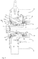
- the first end face 14a corresponds to the drive side of the electrical machine 1, whereas the in Fig. 2
- the second end face 14b shown represents the rear of the machine 1. This rear side is closed by means of a housing cover 8.
- the jacket 6 is connected or equipped with a jacket cooling device 15, in particular a water cooling circuit, with corresponding inlets and outlets 7 for the supply and discharge of the coolant being shown.
- a jacket cooling device 15 in particular a water cooling circuit
- These bores are preferably connected alternately on the face side by milling between two bores each (for example bore 1 on bore 2 at the front, bore 2 on 3 at the rear, 3 on 4 at the front, etc.).
- the inlet and / or outlet 7 can be arranged centrally above and below.
- the cooling water is preferably introduced from below, then flows in a zigzag through the machine half to the left and the other half to the right and comes out again at the top.
- the jacket can have further inlets and outlets 7.
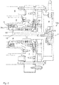
- Figure 3 shows a longitudinal section through the electrical machine 1.
- a stator 2 can be seen therein, which is provided with windings (not shown in the figures) for generating a magnetic field, in particular a rotating field.
- a rotor 3 extends inside the stator 2 and beyond it, the rotor windings being located within the rotor core 3a.
- the rotor package 3a is delimited by two opposite end faces, on each of which a first (inner) heat exchange element 9 is attached.
- a corresponding second (inner) heat exchange element 10 lies opposite this first heat exchange element 9, the respective first and second heat exchange elements 9 and 10 together forming a heat exchange device.
- the first heat exchange elements 9 connected to the end face of the rotor core 3 a are In the exemplary embodiment shown, it is connected to a shaft 4 of the rotor 3 via a tongue and groove connection, but can be connected to the rotor 3 in a rotationally fixed manner in any other manner.
- the corresponding second heat exchange elements 10 are connected to the stator 2 in a rotationally fixed manner and are each attached to a cover element 11.
- the cover element 11 is designed as a bearing shell in which a bearing 12 for supporting the shaft 4 is received.
- the cover elements 11 are firmly connected to the stator 2, so that the second heat exchange elements 10 are connected to the stator 2 in a rotationally fixed manner by means of the cover elements 11. More details on the arrangement of the heat exchange elements 9 and 10 and other components are now with a view to Figures 4 to 8 discussed.
- FIG. 11 shows a detailed view of the front, drive-side area of the electrical machine 1 according to the sectional illustration from FIG Figure 3 .
- a first heat exchange element 9 is thermally connected to an end face of the rotor assembly 3a, with a second heat exchange element 10 opposite this first heat exchange element 9, which is connected to an inner side of the cover element 11 facing the rotor assembly 3a.
- These two heat exchange elements together form an internal heat exchange device.
- the transition area between the heat exchange elements 9, 10 and the rotor package 3a or the cover element 11 is preferably provided with thermal paste.
- FIG. 4 a further first (outer) heat exchange element 9 can be seen, which is connected to the shaft 4 at a front end of the shaft 4.
- a corresponding second (outer) heat exchange element 10 is arranged on the outside of the cover element 11 and is designed in such a way that an in the cover element 11 recorded bearing 12 is secured by a stop surface 10b of the second heat exchange element 10 against loosening in the axial direction.
- the heat exchange elements 9 'and 10' arranged on the outside of the cover element 11 together form an outer heat exchange device. Unless otherwise stated, what was said about the inner heat exchange elements 9 and 10 applies to the outer heat exchange elements 9 ′ and 10 ′.
- the second heat exchange elements 10 and 10 ′ are fixedly connected to the cover elements 11 by means of corresponding screw connections.
- the first heat exchange elements 9, on the other hand, follow the rotational movement of the rotor 3 and transfer the thermal energy absorbed in the shaft 4 and / or in the rotor package 3a to the respective opposite second heat exchange element 10, which in turn transfers the heat to the cover element 11.
- the cover element 11 usually has a lower temperature, in particular when the electrical machine 1 has a jacket cooling device 15 connected to the cover element 11.
- the heat exchange between the first and the second heat exchange elements 9 or 9 'and 10 or 10' takes place via the heat exchange surfaces 9a or 10a (for the sake of simplicity, only one surface of the inner heat exchange device was shown in Fig. 4 provided with a reference number, Figures 6 and 7 show a more detailed representation, the surfaces are provided in the outer heat exchange device in an analogous manner), which extend at least in a partial area from an end face of the rotor 3 in a direction along the rotor 3 and at least within this partial area each other in the radial direction of the rotor 3 opposite.
- the heat exchange surfaces 9a and 10a are also arranged concentrically to the axis of rotation x of the rotor 3 or the shaft 4.
- the first and second heat exchange elements 9 and 10 each have at least two annular projections 9c, 10c, the heat exchange surfaces 9a and 10a being formed on the surface of the projections 9c and 10c.
- the heat exchange surfaces 9a and 10a preferably extend along the entire surface of the projections 9c and 10c.
- the heat exchange surfaces 9a or 10a could also extend only along one or more individual sections of the surface of the projections 9c or 10c.
- the heat exchange elements 9 and 10 are preferably designed in such a way that the projections 9c of the first heat exchange element 9 extend into areas between the projections 10c of the second heat exchange element 10 and / or vice versa.
- the heat exchange surfaces 9a and 10a do not touch one another and are spaced apart from one another between 0.3 mm and 10 mm, preferably between 0.3 mm and 2 mm, depending on the dimensions of the electrical machine 1 and the heat exchange elements 9 and 10.
- a fluid or medium preferably air, is located between the heat exchange surfaces 9 and 10, it being possible for the heat to be transferred between the surfaces through the fluid or medium by convection.
- the heat exchange surfaces 10a of the second heat exchange element 10 and the heat exchange surfaces 9a of the first heat exchange element 9 extend, as already mentioned, in a partial area starting from an end face of the rotor 3 in a direction along the rotor 3, the heat exchange surfaces 9a, 10a of this partial area in each other Opposite the radial direction of the rotor 3 and are arranged concentrically to the axis of rotation of the rotor 3.
- the partial area covers at least 50%, preferably at least 80% of the extent of the heat exchange surfaces 9a and 10a in the direction along the rotor 3 or in the axial direction x.
- Figure 4 also shows an opening 5 running inside the shaft 4 which runs from the end face of the shaft 4 in a direction along the axis of rotation x. At least one, preferably precisely one, heat-conducting element 13 is inserted into this opening, the heat element 13 being made of a material which has a higher thermal conductivity than the material of the shaft 4.
- this opening 5 is located in an outer region of the shaft 4, the outer region extending at a distance of R / 2 to R from the center of the shaft, where R is the radius of the shaft.
- the number of these openings 5 can in principle be freely selected and primarily follows the structural and thermal requirements of the electrical machine. In the embodiment shown, five openings 5 with heat conducting elements 13 received therein are provided by way of example.
- the openings 5 and the heat-conducting elements 13 preferably extend beyond the bearing 12 and thus make it possible to specifically dissipate friction losses of the bearings, which could lead to problematic heating, particularly on the bearing inner ring.
- the openings 5 as well as the heat conducting elements 13 end in the embodiment shown in front of the rotor package 3a of the rotor 3, but could alternatively also extend along the shaft 4 to within the rotor package 3a in order to dissipate power dissipated within the rotor package to the outside. This variant can be particularly advantageous in asynchronous machines in which the rotor power loss is generally higher than in synchronous machines with a comparable rated power.
- FIG. 11 shows a detailed view of the rear, rear area of the sectional illustration according to FIG Figure 3 .
- the second end face 14b of the machine faces away from the drive side and is closed by means of the housing cover 8.
- the mechanical structure of the The rear of the electrical machine 1 in the embodiment shown largely corresponds to the structure of the front of the machine 1.
- the electrical machine 1 therefore also has a first heat exchange element 9 on the end of the rotor core 3 facing the rear side, which is opposite a second heat exchange element 10, this second heat exchange element 10 being attached to the inside of a cover element 11.
- the two heat exchange elements 9 and 10 therefore form an inner heat exchange device, as they are already seen together Fig. 4 has been described.
- the shaft 4 also has openings 5 on its rear face, which are designed to accommodate heat-conducting elements 13.
- the openings 5 (both on the front side and on the rear side of the shaft 4) have a bore 14 penetrating outwardly through the shaft 4, the bore 14 being arranged in an end region of the opening 5 facing away from the end face, so that this during the Inserting a heat-conducting element 13 into the opening 5 allows excess air, adhesive and / or heat-conducting paste to escape.
- FIG. 6 shows a perspective illustration of an exemplary first heat exchange element 9 of an internal heat exchange device.
- This first heat exchange element 9 has two ring-shaped projections 9c, on whose inner and outer surfaces heat exchange surfaces 9a are formed.
- the first heat exchange element 9 has an inner fixing ring 9d, which has two mutually opposite groove-shaped recesses, by means of which the first heat exchange element 9 can be connected to the shaft 4 in a rotationally fixed manner. These recesses ensure a positionally accurate alignment of the first heat exchange element 9 with respect to the shaft 4. This can be of particular importance, for example if the first heat exchange element 9 has corresponding balancing weights and / or material removal is equipped to compensate for an imbalance in the shaft.
- the inner fixing ring 9d has an additional heat exchange surface 9a on its outside, so that the first heat exchange element 9 in this embodiment has a total of five heat exchange surfaces 9a.
- FIG. 11 shows a perspective illustration of a to the first heat exchange element 9 according to FIG Fig. 6 Corresponding second heat exchange element 10.
- This heat exchange element 10 has three annular projections 10c, which are arranged such that the projections 9c of the first heat exchange element 9 engage in the recesses formed between the projections 10c and can rotate therein.
- the opposing heat exchange elements 9 and 10 are therefore preferably sleeve-shaped or drum-shaped.
- Figure 8 shows a perspective illustration of the rotor 3 of the electrical machine 1 according to Figure 1 .
- This shows two first heat exchange elements 9, which are arranged on the end faces of the rotor core 3a.
- drive-side first heat exchange element 9 balancing openings 9e can be seen, into which balancing weights (not shown here) can be inserted or which can be enlarged by enlarging the bores or which result in balancing through the removal of material.
- the openings 5 can also be clearly seen, into which heat-conducting elements 13, not visible in this figure, are inserted.
- the bearings 12 can be any bearings known to a person skilled in the art that are suitable for supporting the shaft 4. As already mentioned, this can be, for example, fixed or loose bearings.
- a fixed bearing is preferably located on one side of the shaft 4 and a floating bearing on the opposite side in order to absorb thermal expansion of the shaft 4 in the axial direction.
- the openings 5 and heat conducting elements 13 and / or the heat exchange device (s) are preferably dimensioned so that the maximum rotor heating and / or the maximum inner bearing temperature can be reduced by at least 5 Kelvin, preferably at least 20 Kelvin, compared to a conventional design.
- the heat conducting elements 13 are inserted into the openings 5 with a loose fit.
- the openings 5 are arranged in such a way that the common geometric center of gravity of the heat-conducting elements 13 arranged therein lies on the axis of rotation x of the shaft 4 or of the rotor 3.
- the heat conducting elements fill the cross-sectional area of the openings 5 preferably at least 95%, particularly preferably 98% or 99%, and in a favorable embodiment consist of copper, copper alloys and / or aluminum.
- the heat conducting elements 13 are rod-shaped with a circular cross section.
- the invention makes it possible to lower the rotor temperature and / or the bearing temperature by means of the heat exchange device and / or the heat conducting elements 13.
- the person skilled in the art is able to arrive at other embodiments of the invention that are not shown.
- the invention is therefore not restricted to the embodiments shown.
- Individual aspects of the invention or the embodiments can also be taken up and combined with one another. What is essential are the ideas on which the invention is based, which can be carried out in various ways by a person skilled in the art with knowledge of this description and which are nevertheless maintained as such.
Landscapes
- Engineering & Computer Science (AREA)
- Power Engineering (AREA)
- Physics & Mathematics (AREA)
- Thermal Sciences (AREA)
- Motor Or Generator Cooling System (AREA)
Claims (19)
- Machine électrique (1) comportant un stator (2) et un rotor (3) disposé au moins partiellement à l'intérieur du stator (2) et comportant un arbre (4), ledit arbre (4) présentant sur au moins une face d'extrémité au moins une ouverture (5) s'étendant dans une direction le long de l'axe de rotation (x) de l'arbre (4), au moins un élément conducteur de chaleur (13) étant inséré dans ladite ouverture,
caractérisée en ce que l'élément conducteur de chaleur (13) est complètement fabriqué en un matériau ayant une conductivité thermique plus élevée que le matériau de l'arbre (4) et occupe au moins 95% de la section transversale de l'ouverture (5). - Machine électrique (1) selon la revendication 1, caractérisée en ce que ladite au moins une ouverture (5) s'étend parallèle à l'axe de rotation (x) de l'arbre (4).
- Machine électrique (1) selon la revendication 1 ou 2, caractérisée en ce que ladite au moins une ouverture (5) et l'élément conducteur de chaleur (13) reçu dans celle-ci ont la même forme de section transversale, de préférence une section transversale circulaire.
- Machine électrique (1) selon la revendication 3, caractérisée en ce que ledit au moins un élément conducteur de chaleur (13) est inséré avec un ajustement glissant dans ladite au moins une ouverture (5).
- Machine électrique (1) selon l'une des revendications 1 à 4, caractérisée en ce que l'arbre (4) présente au moins deux ou plusieurs ouvertures (5) dans chacune desquelles au moins un élément conducteur de chaleur (13) est inséré.
- Machine électrique (1) selon la revendication 5, caractérisée en ce que les ouvertures (5) sont disposées de telle sorte que le centre de gravité géométrique commun des éléments conducteurs de chaleur (13) disposés là-dedans est situé sur l'axe de rotation (x) de l'arbre (4).
- Machine électrique (1) selon la revendication 5 ou 6, caractérisée en ce que lesdites ouvertures (5) sont disposées dans une région extérieure de l'arbre (4) qui s'étend à une distance entre R/2 et R du centre de l'arbre (4), où R est le rayon de l'arbre (4).
- Machine électrique (1) selon l'une des revendications 1 à 7, caractérisée en ce que ladite au moins une ouverture (5) et/ou l'au moins un élément conducteur de chaleur (13) s'étendent depuis une première ou une deuxième face d'extrémité de l'arbre (4) le long de l'axe de rotation (x) dans la direction de la deuxième ou première face d'extrémité opposée, au moins jusqu'à la zone du palier (12) associé à la première ou la deuxième face d'extrémité, de préférence au moins jusqu'à un ensemble rotor (3a) du rotor (3), particulièrement préférée au moins jusqu'à une zone située à l'intérieur de l'ensemble rotor (3a).
- Machine électrique (1) selon l'une des revendications 1 à 8, caractérisée en ce que ladite au moins une ouverture (5) présente un alésage (14) pénétrant l'arbre (4) vers l'extérieur, de préférence dans la direction radiale, l'alésage (14) étant de préférence disposé dans une zone d'extrémité de l'ouverture (5) opposée à la face d'extrémité, cette zone d'extrémité étant exempte d'éléments conducteurs de chaleur (13).
- Machine électrique (1) selon l'une des revendications 1 à 9, caractérisée en ce que la surface totale de la section transversale des ouvertures (5) occupe un pourcentage de surface de 5 à 50%, de préférence de 15 à 30%, de manière particulièrement préférée de 15 à 20% de la surface de section transversale de l'arbre (4).
- Machine électrique (1) selon l'une des revendications 1 à 10, caractérisée en ce que la machine électrique (1) comporte au moins un dispositif d'échange de chaleur ayant au moins un premier élément d'échange de chaleur (9) connecté de manière non-rotative au rotor (3) et au moins un deuxième élément d'échange de chaleur (10) connecté de manière non-rotative au stator (2), le premier et le deuxième élément d'échange de chaleur (9, 10) ayant chacun au moins une surface d'échange de chaleur (9a, 10a), les surfaces d'échange de chaleur (9a, 10a) s'étendant, au moins dans une zone partielle, à partir d'une face d'extrémité du rotor (3) dans une direction le long du rotor (3) et les surfaces d'échange thermique (9a, 10a) sont opposées l'une à l'autre dans la direction radiale du rotor (3) au moins à l'intérieur de cette zone partielle et sont agencées concentriquement à l'axe de rotation (x) du rotor (3).
- Machine électrique (1) selon la revendication 11, caractérisée en ce que le premier élément d'échange de chaleur (9) et/ou le deuxième élément d'échange de chaleur (10) comportent au moins une, de préférence deux ou plusieurs saillies (9c, 10c) au moins annulaires en sections, les surfaces d'échange de chaleur (9a, 10a) étant formées sur la surface des saillies (9c, 10c).
- Machine électrique (1) selon la revendication 12, caractérisée en ce que les saillies individuelles (9c, 10c) du premier élément d'échange thermique (9) s'étendent dans des zones situées entre les saillies (9c, 10c) du deuxième élément d'échange thermique (10) et/ou vice versa.
- Machine électrique (1) selon l'une des revendications 11 à 13, caractérisée en ce qu'au moins un dispositif d'échange de chaleur interne est prévu, qui est disposé entre deux éléments de couvercle (11) de la machine électrique qui sont disposés côté face d'extrémité et qui sont rigidement connectés au stator (2), le premier élément d'échange de chaleur (9) du dispositif d'échange de chaleur interne étant fixé à une extrémité d'un ensemble de rotor (3a) et est relié thermiquement à l'ensemble de rotor (3a) et le deuxième élément d'échange de chaleur (10) du dispositif d'échange de chaleur interne étant fixé à l'élément de couvercle (11) adjacent et étant relié thermiquement à celui-ci.
- Machine électrique (1) selon l'une des revendications 11 à 14, caractérisée en ce qu'au moins un dispositif d'échange de chaleur externe est prévu, le premier élément d'échange de chaleur (9) du dispositif d'échange de chaleur externe étant relié mécaniquement et thermiquement à l'arbre (4) du rotor (3) et le deuxième élément d'échange de chaleur (10) étant connecté à un élément de couvercle (11) disposé sur une face d'extrémité de la machine électrique (1) et rigidement fixé au stator (2) et relié thermiquement à celui-ci.
- Machine électrique (1) selon la revendication 14 ou 15, caractérisée en ce que l'élément de couvercle respectif (11) est une plaque d'appui, au moins un roulement (12) étant reçu dans la plaque d'appui pour supporter l'arbre (4) du rotor (3).
- Machine électrique (1) selon la revendication 16, caractérisée en ce que le deuxième élément d'échange thermique (10) du dispositif d'échange thermique externe est disposé sur la plaque d'appui, le deuxième élément d'échange thermique (10) ayant de préférence une surface d'appui (10b) sécurisant un palier (12) reçu dans la plaque d'appui contre un déplacement dans la direction de l'axe de rotation (x) la tige (4).
- Machine électrique (1) selon l'une des revendications 11 à 17, caractérisée en ce que le(s) dispositif(s) d'échange de chaleur, en particulier le(s) dispositif(s) d'échange de chaleur interne et/ou externe(s) est/sont disposé(s) du côté entrainement et/ou du côté arrière opposé de la machine électrique (1).
- Machine électrique (1) selon l'une des revendications 11 à 18, caractérisée en ce que le stator (2) comporte au moins un dispositif de refroidissement de l'habillage (15) ou est connecté à celui-ci, le dispositif de refroidissement de l'habillage (15) comportant de préférence des ailettes de refroidissement pour le refroidissement par air et/ou un circuit de refroidissement refroidi par eau.
Applications Claiming Priority (2)
| Application Number | Priority Date | Filing Date | Title |
|---|---|---|---|
| ATA477/2015A AT517533B1 (de) | 2015-07-20 | 2015-07-20 | Elektrische Maschine |
| PCT/EP2016/067235 WO2017013144A1 (fr) | 2015-07-20 | 2016-07-20 | Machine électrique |
Publications (2)
| Publication Number | Publication Date |
|---|---|
| EP3326272A1 EP3326272A1 (fr) | 2018-05-30 |
| EP3326272B1 true EP3326272B1 (fr) | 2020-12-16 |
Family
ID=56464207
Family Applications (1)
| Application Number | Title | Priority Date | Filing Date |
|---|---|---|---|
| EP16741016.6A Active EP3326272B1 (fr) | 2015-07-20 | 2016-07-20 | Machine électrique |
Country Status (5)
| Country | Link |
|---|---|
| US (1) | US20180212494A1 (fr) |
| EP (1) | EP3326272B1 (fr) |
| CN (1) | CN108028578A (fr) |
| AT (1) | AT517533B1 (fr) |
| WO (1) | WO2017013144A1 (fr) |
Families Citing this family (5)
| Publication number | Priority date | Publication date | Assignee | Title |
|---|---|---|---|---|
| DE102018215608A1 (de) * | 2018-09-13 | 2020-03-19 | Mahle International Gmbh | Elektrische Maschine, insbesondere für ein Fahrzeug |
| DE102018215607A1 (de) | 2018-09-13 | 2020-03-19 | Mahle International Gmbh | Elektrische Maschine, insbesondere für ein Fahrzeug |
| US11374458B2 (en) * | 2018-10-24 | 2022-06-28 | Dekalb Blower Inc. | Electric motor with fluid cooling |
| US11336151B2 (en) * | 2019-05-06 | 2022-05-17 | Rolls-Royce Plc | Fluid cooling of grease-packed bearings |
| EP3799264B1 (fr) | 2019-09-30 | 2023-04-19 | Siemens Aktiengesellschaft | Arbre d'entraînement d'une machine dynamoélectrique |
Citations (3)
| Publication number | Priority date | Publication date | Assignee | Title |
|---|---|---|---|---|
| DE102009012324A1 (de) * | 2009-03-09 | 2010-09-16 | Siemens Aktiengesellschaft | Elektrische Maschine mit Wärmeumlaufkühlung |
| DE102012203691A1 (de) * | 2012-03-08 | 2013-09-12 | Siemens Aktiengesellschaft | Kühleinrichtung für einen Rotor einer elektrischen Maschine |
| US20140368064A1 (en) * | 2013-06-13 | 2014-12-18 | Tesla Motors, Inc. | Rotor Assembly with Heat Pipe Cooling System |
Family Cites Families (19)
| Publication number | Priority date | Publication date | Assignee | Title |
|---|---|---|---|---|
| US3447003A (en) * | 1967-03-02 | 1969-05-27 | Nasa | Generator for a space power system |
| US4234293A (en) * | 1979-03-27 | 1980-11-18 | Dresser Industries, Inc. | Axial balancing system for motor driven pumps |
| US4574210A (en) * | 1983-07-07 | 1986-03-04 | Wilhelm Gebhardt Gmbh | External rotor motor having a cooling system |
| JPS60176436A (ja) * | 1984-02-22 | 1985-09-10 | Matsushita Electric Ind Co Ltd | 電動機 |
| US6100615A (en) * | 1998-05-11 | 2000-08-08 | Birkestrand; Orville J. | Modular motorized electric wheel hub assembly for bicycles and the like |
| JP3675322B2 (ja) * | 2000-09-18 | 2005-07-27 | 株式会社日立製作所 | 車両用交流発電機 |
| US7327055B2 (en) * | 2002-07-26 | 2008-02-05 | John Devine | Permanent magnet generator with an integral cooling system |
| DE102005005283A1 (de) * | 2005-02-04 | 2006-08-17 | Siemens Ag | Maschinenanlage mit Thermosyphon-Kühlung ihrer supraleitenden Rotorwicklung |
| DE102006045178A1 (de) * | 2006-09-25 | 2008-04-03 | Siemens Ag | Elektrische Maschine |
| JP5374312B2 (ja) * | 2009-10-09 | 2013-12-25 | Ntn株式会社 | インホイールモータ駆動装置 |
| EP2365610A1 (fr) * | 2010-03-09 | 2011-09-14 | Siemens Aktiengesellschaft | Moteur électrique incorporant un refroidissement de rotor interne |
| US8482169B2 (en) * | 2010-06-14 | 2013-07-09 | Remy Technologies, Llc | Electric machine cooling system and method |
| CN102075041B (zh) * | 2010-11-25 | 2012-07-04 | 西安交通大学 | 一种带有流体强制冷却的v形气隙横向磁场力矩电机 |
| US9331551B2 (en) * | 2011-02-18 | 2016-05-03 | Honda Motor Co., Ltd. | Case of electric rotating machine |
| DE102012203697A1 (de) * | 2012-03-08 | 2013-09-12 | Siemens Aktiengesellschaft | Elektrische Maschine mit einem Rotor zur Kühlung der elektrischen Maschine |
| US20130342052A1 (en) * | 2012-06-22 | 2013-12-26 | GM Global Technology Operations LLC | Electric machine with circumferential rotor and housing fins |
| CN103023219B (zh) * | 2012-12-14 | 2015-05-13 | 上海亿力电器有限公司 | 水冷电机 |
| CN203104240U (zh) * | 2013-01-31 | 2013-07-31 | 史久云 | 水冷轴无刷同步发电机 |
| CN104659967B (zh) * | 2013-11-21 | 2017-07-21 | 於贻鹏 | 相变散热电机 |
-
2015
- 2015-07-20 AT ATA477/2015A patent/AT517533B1/de not_active IP Right Cessation
-
2016
- 2016-07-20 US US15/745,716 patent/US20180212494A1/en not_active Abandoned
- 2016-07-20 WO PCT/EP2016/067235 patent/WO2017013144A1/fr active Application Filing
- 2016-07-20 EP EP16741016.6A patent/EP3326272B1/fr active Active
- 2016-07-20 CN CN201680042537.1A patent/CN108028578A/zh active Pending
Patent Citations (3)
| Publication number | Priority date | Publication date | Assignee | Title |
|---|---|---|---|---|
| DE102009012324A1 (de) * | 2009-03-09 | 2010-09-16 | Siemens Aktiengesellschaft | Elektrische Maschine mit Wärmeumlaufkühlung |
| DE102012203691A1 (de) * | 2012-03-08 | 2013-09-12 | Siemens Aktiengesellschaft | Kühleinrichtung für einen Rotor einer elektrischen Maschine |
| US20140368064A1 (en) * | 2013-06-13 | 2014-12-18 | Tesla Motors, Inc. | Rotor Assembly with Heat Pipe Cooling System |
Also Published As
| Publication number | Publication date |
|---|---|
| AT517533A1 (de) | 2017-02-15 |
| US20180212494A1 (en) | 2018-07-26 |
| EP3326272A1 (fr) | 2018-05-30 |
| AT517533B1 (de) | 2017-06-15 |
| WO2017013144A1 (fr) | 2017-01-26 |
| CN108028578A (zh) | 2018-05-11 |
Similar Documents
| Publication | Publication Date | Title |
|---|---|---|
| EP3326272B1 (fr) | Machine électrique | |
| EP3501085B1 (fr) | Machine électrique et véhicule équipé de la machine électrique | |
| EP2299565B1 (fr) | Rotor d`une machine électrique asynchrone avec moyen de refroidissement | |
| EP3017528B1 (fr) | Machine électrique pourvue d'un dispositif thermoconducteur | |
| WO2018137955A1 (fr) | Procédé de refroidissement d'une machine électrique, et machine électrique dans laquelle ce procédé est appliqué | |
| EP3504774B1 (fr) | Rotor en court circuit pour une machine asynchrone | |
| DE102006045178A1 (de) | Elektrische Maschine | |
| EP1153467B1 (fr) | Machine electrique | |
| DE102010063973A1 (de) | Elektrische Maschine mit einer Kühleinrichtung | |
| DE102017202752A1 (de) | Rotor für eine elektrische Maschine | |
| EP3063857B1 (fr) | Refroidissement d'une pièce active d'une machine électrique | |
| EP1145409A2 (fr) | Machine electrique | |
| DE102016218872A1 (de) | Kühlung eines elektrischen Gondelantriebs | |
| DE102012204197A1 (de) | Elektrische Maschine mit Phasentrenner | |
| EP3205004B1 (fr) | Rotor à cage destiné à un moteur électrique asynchrone, muni d'un disque de support stabilisant la bague de court-circuit | |
| EP2982021B1 (fr) | Carter pour un moteur électrique | |
| EP3308449B1 (fr) | Anneau de stator pour générateur électrique et générateur et éolienne équipé de celui-ci | |
| WO2016055199A2 (fr) | Rotor à cage pour machine électrique asynchrone comportant des tirants qui stabilisent une bague de court-circuit | |
| EP2226920A2 (fr) | Système de cogénération avec un moteur à combustion à piston et une machine électrique | |
| WO2010025986A2 (fr) | Machine dynamoélectrique à système de refroidissement | |
| AT15065U1 (de) | Elektrische Maschine | |
| EP3324516B1 (fr) | Machine électrique | |
| DE102018202172A1 (de) | Antriebsvorrichtung für ein Luftfahrzeug mit elektrischer Maschine und Kühleinrichtung | |
| EP1032113A1 (fr) | Dispositif de refroidissement pour une machine électrique, notamment pour une machine à champ tournant | |
| EP0548733A2 (fr) | Moteur électrique propre à être utilisé en immersion |
Legal Events
| Date | Code | Title | Description |
|---|---|---|---|
| STAA | Information on the status of an ep patent application or granted ep patent |
Free format text: STATUS: THE INTERNATIONAL PUBLICATION HAS BEEN MADE |
|
| PUAI | Public reference made under article 153(3) epc to a published international application that has entered the european phase |
Free format text: ORIGINAL CODE: 0009012 |
|
| STAA | Information on the status of an ep patent application or granted ep patent |
Free format text: STATUS: REQUEST FOR EXAMINATION WAS MADE |
|
| 17P | Request for examination filed |
Effective date: 20180115 |
|
| AK | Designated contracting states |
Kind code of ref document: A1 Designated state(s): AL AT BE BG CH CY CZ DE DK EE ES FI FR GB GR HR HU IE IS IT LI LT LU LV MC MK MT NL NO PL PT RO RS SE SI SK SM TR |
|
| AX | Request for extension of the european patent |
Extension state: BA ME |
|
| REG | Reference to a national code |
Ref country code: DE Ref legal event code: R079 Ref document number: 502016011987 Country of ref document: DE Free format text: PREVIOUS MAIN CLASS: H02K0009220000 Ipc: H02K0001200000 |
|
| DAV | Request for validation of the european patent (deleted) | ||
| DAX | Request for extension of the european patent (deleted) | ||
| RIC1 | Information provided on ipc code assigned before grant |
Ipc: H02K 5/18 20060101ALI20181023BHEP Ipc: H02K 7/08 20060101ALI20181023BHEP Ipc: H02K 1/20 20060101AFI20181023BHEP Ipc: H02K 9/10 20060101ALI20181023BHEP Ipc: H02K 9/19 20060101ALI20181023BHEP Ipc: H02K 9/22 20060101ALI20181023BHEP Ipc: H02K 5/15 20060101ALI20181023BHEP Ipc: H02K 7/00 20060101ALI20181023BHEP |
|
| STAA | Information on the status of an ep patent application or granted ep patent |
Free format text: STATUS: EXAMINATION IS IN PROGRESS |
|
| 17Q | First examination report despatched |
Effective date: 20181211 |
|
| GRAP | Despatch of communication of intention to grant a patent |
Free format text: ORIGINAL CODE: EPIDOSNIGR1 |
|
| STAA | Information on the status of an ep patent application or granted ep patent |
Free format text: STATUS: GRANT OF PATENT IS INTENDED |
|
| INTG | Intention to grant announced |
Effective date: 20200720 |
|
| GRAS | Grant fee paid |
Free format text: ORIGINAL CODE: EPIDOSNIGR3 |
|
| GRAA | (expected) grant |
Free format text: ORIGINAL CODE: 0009210 |
|
| STAA | Information on the status of an ep patent application or granted ep patent |
Free format text: STATUS: THE PATENT HAS BEEN GRANTED |
|
| AK | Designated contracting states |
Kind code of ref document: B1 Designated state(s): AL AT BE BG CH CY CZ DE DK EE ES FI FR GB GR HR HU IE IS IT LI LT LU LV MC MK MT NL NO PL PT RO RS SE SI SK SM TR |
|
| REG | Reference to a national code |
Ref country code: GB Ref legal event code: FG4D Free format text: NOT ENGLISH |
|
| REG | Reference to a national code |
Ref country code: DE Ref legal event code: R096 Ref document number: 502016011987 Country of ref document: DE |
|
| REG | Reference to a national code |
Ref country code: IE Ref legal event code: FG4D Free format text: LANGUAGE OF EP DOCUMENT: GERMAN |
|
| REG | Reference to a national code |
Ref country code: AT Ref legal event code: REF Ref document number: 1346491 Country of ref document: AT Kind code of ref document: T Effective date: 20210115 |
|
| PG25 | Lapsed in a contracting state [announced via postgrant information from national office to epo] |
Ref country code: GR Free format text: LAPSE BECAUSE OF FAILURE TO SUBMIT A TRANSLATION OF THE DESCRIPTION OR TO PAY THE FEE WITHIN THE PRESCRIBED TIME-LIMIT Effective date: 20210317 Ref country code: FI Free format text: LAPSE BECAUSE OF FAILURE TO SUBMIT A TRANSLATION OF THE DESCRIPTION OR TO PAY THE FEE WITHIN THE PRESCRIBED TIME-LIMIT Effective date: 20201216 Ref country code: NO Free format text: LAPSE BECAUSE OF FAILURE TO SUBMIT A TRANSLATION OF THE DESCRIPTION OR TO PAY THE FEE WITHIN THE PRESCRIBED TIME-LIMIT Effective date: 20210316 Ref country code: RS Free format text: LAPSE BECAUSE OF FAILURE TO SUBMIT A TRANSLATION OF THE DESCRIPTION OR TO PAY THE FEE WITHIN THE PRESCRIBED TIME-LIMIT Effective date: 20201216 |
|
| REG | Reference to a national code |
Ref country code: NL Ref legal event code: MP Effective date: 20201216 |
|
| PG25 | Lapsed in a contracting state [announced via postgrant information from national office to epo] |
Ref country code: SE Free format text: LAPSE BECAUSE OF FAILURE TO SUBMIT A TRANSLATION OF THE DESCRIPTION OR TO PAY THE FEE WITHIN THE PRESCRIBED TIME-LIMIT Effective date: 20201216 Ref country code: BG Free format text: LAPSE BECAUSE OF FAILURE TO SUBMIT A TRANSLATION OF THE DESCRIPTION OR TO PAY THE FEE WITHIN THE PRESCRIBED TIME-LIMIT Effective date: 20210316 Ref country code: LV Free format text: LAPSE BECAUSE OF FAILURE TO SUBMIT A TRANSLATION OF THE DESCRIPTION OR TO PAY THE FEE WITHIN THE PRESCRIBED TIME-LIMIT Effective date: 20201216 |
|
| PG25 | Lapsed in a contracting state [announced via postgrant information from national office to epo] |
Ref country code: HR Free format text: LAPSE BECAUSE OF FAILURE TO SUBMIT A TRANSLATION OF THE DESCRIPTION OR TO PAY THE FEE WITHIN THE PRESCRIBED TIME-LIMIT Effective date: 20201216 Ref country code: NL Free format text: LAPSE BECAUSE OF FAILURE TO SUBMIT A TRANSLATION OF THE DESCRIPTION OR TO PAY THE FEE WITHIN THE PRESCRIBED TIME-LIMIT Effective date: 20201216 |
|
| REG | Reference to a national code |
Ref country code: LT Ref legal event code: MG9D |
|
| PG25 | Lapsed in a contracting state [announced via postgrant information from national office to epo] |
Ref country code: SK Free format text: LAPSE BECAUSE OF FAILURE TO SUBMIT A TRANSLATION OF THE DESCRIPTION OR TO PAY THE FEE WITHIN THE PRESCRIBED TIME-LIMIT Effective date: 20201216 Ref country code: PT Free format text: LAPSE BECAUSE OF FAILURE TO SUBMIT A TRANSLATION OF THE DESCRIPTION OR TO PAY THE FEE WITHIN THE PRESCRIBED TIME-LIMIT Effective date: 20210416 Ref country code: RO Free format text: LAPSE BECAUSE OF FAILURE TO SUBMIT A TRANSLATION OF THE DESCRIPTION OR TO PAY THE FEE WITHIN THE PRESCRIBED TIME-LIMIT Effective date: 20201216 Ref country code: EE Free format text: LAPSE BECAUSE OF FAILURE TO SUBMIT A TRANSLATION OF THE DESCRIPTION OR TO PAY THE FEE WITHIN THE PRESCRIBED TIME-LIMIT Effective date: 20201216 Ref country code: CZ Free format text: LAPSE BECAUSE OF FAILURE TO SUBMIT A TRANSLATION OF THE DESCRIPTION OR TO PAY THE FEE WITHIN THE PRESCRIBED TIME-LIMIT Effective date: 20201216 Ref country code: SM Free format text: LAPSE BECAUSE OF FAILURE TO SUBMIT A TRANSLATION OF THE DESCRIPTION OR TO PAY THE FEE WITHIN THE PRESCRIBED TIME-LIMIT Effective date: 20201216 Ref country code: LT Free format text: LAPSE BECAUSE OF FAILURE TO SUBMIT A TRANSLATION OF THE DESCRIPTION OR TO PAY THE FEE WITHIN THE PRESCRIBED TIME-LIMIT Effective date: 20201216 |
|
| PG25 | Lapsed in a contracting state [announced via postgrant information from national office to epo] |
Ref country code: PL Free format text: LAPSE BECAUSE OF FAILURE TO SUBMIT A TRANSLATION OF THE DESCRIPTION OR TO PAY THE FEE WITHIN THE PRESCRIBED TIME-LIMIT Effective date: 20201216 |
|
| REG | Reference to a national code |
Ref country code: DE Ref legal event code: R097 Ref document number: 502016011987 Country of ref document: DE |
|
| PG25 | Lapsed in a contracting state [announced via postgrant information from national office to epo] |
Ref country code: IS Free format text: LAPSE BECAUSE OF FAILURE TO SUBMIT A TRANSLATION OF THE DESCRIPTION OR TO PAY THE FEE WITHIN THE PRESCRIBED TIME-LIMIT Effective date: 20210416 |
|
| PLBE | No opposition filed within time limit |
Free format text: ORIGINAL CODE: 0009261 |
|
| STAA | Information on the status of an ep patent application or granted ep patent |
Free format text: STATUS: NO OPPOSITION FILED WITHIN TIME LIMIT |
|
| PG25 | Lapsed in a contracting state [announced via postgrant information from national office to epo] |
Ref country code: IT Free format text: LAPSE BECAUSE OF FAILURE TO SUBMIT A TRANSLATION OF THE DESCRIPTION OR TO PAY THE FEE WITHIN THE PRESCRIBED TIME-LIMIT Effective date: 20201216 Ref country code: AL Free format text: LAPSE BECAUSE OF FAILURE TO SUBMIT A TRANSLATION OF THE DESCRIPTION OR TO PAY THE FEE WITHIN THE PRESCRIBED TIME-LIMIT Effective date: 20201216 |
|
| 26N | No opposition filed |
Effective date: 20210917 |
|
| PG25 | Lapsed in a contracting state [announced via postgrant information from national office to epo] |
Ref country code: DK Free format text: LAPSE BECAUSE OF FAILURE TO SUBMIT A TRANSLATION OF THE DESCRIPTION OR TO PAY THE FEE WITHIN THE PRESCRIBED TIME-LIMIT Effective date: 20201216 |
|
| PG25 | Lapsed in a contracting state [announced via postgrant information from national office to epo] |
Ref country code: ES Free format text: LAPSE BECAUSE OF FAILURE TO SUBMIT A TRANSLATION OF THE DESCRIPTION OR TO PAY THE FEE WITHIN THE PRESCRIBED TIME-LIMIT Effective date: 20201216 |
|
| PG25 | Lapsed in a contracting state [announced via postgrant information from national office to epo] |
Ref country code: SI Free format text: LAPSE BECAUSE OF FAILURE TO SUBMIT A TRANSLATION OF THE DESCRIPTION OR TO PAY THE FEE WITHIN THE PRESCRIBED TIME-LIMIT Effective date: 20201216 |
|
| REG | Reference to a national code |
Ref country code: CH Ref legal event code: PL |
|
| GBPC | Gb: european patent ceased through non-payment of renewal fee |
Effective date: 20210720 |
|
| PG25 | Lapsed in a contracting state [announced via postgrant information from national office to epo] |
Ref country code: MC Free format text: LAPSE BECAUSE OF FAILURE TO SUBMIT A TRANSLATION OF THE DESCRIPTION OR TO PAY THE FEE WITHIN THE PRESCRIBED TIME-LIMIT Effective date: 20201216 |
|
| REG | Reference to a national code |
Ref country code: BE Ref legal event code: MM Effective date: 20210731 |
|
| PG25 | Lapsed in a contracting state [announced via postgrant information from national office to epo] |
Ref country code: LI Free format text: LAPSE BECAUSE OF NON-PAYMENT OF DUE FEES Effective date: 20210731 Ref country code: GB Free format text: LAPSE BECAUSE OF NON-PAYMENT OF DUE FEES Effective date: 20210720 Ref country code: CH Free format text: LAPSE BECAUSE OF NON-PAYMENT OF DUE FEES Effective date: 20210731 |
|
| PG25 | Lapsed in a contracting state [announced via postgrant information from national office to epo] |
Ref country code: IS Free format text: LAPSE BECAUSE OF FAILURE TO SUBMIT A TRANSLATION OF THE DESCRIPTION OR TO PAY THE FEE WITHIN THE PRESCRIBED TIME-LIMIT Effective date: 20210416 Ref country code: LU Free format text: LAPSE BECAUSE OF NON-PAYMENT OF DUE FEES Effective date: 20210720 Ref country code: FR Free format text: LAPSE BECAUSE OF NON-PAYMENT OF DUE FEES Effective date: 20210731 |
|
| PG25 | Lapsed in a contracting state [announced via postgrant information from national office to epo] |
Ref country code: IE Free format text: LAPSE BECAUSE OF NON-PAYMENT OF DUE FEES Effective date: 20210720 Ref country code: BE Free format text: LAPSE BECAUSE OF NON-PAYMENT OF DUE FEES Effective date: 20210731 |
|
| REG | Reference to a national code |
Ref country code: AT Ref legal event code: MM01 Ref document number: 1346491 Country of ref document: AT Kind code of ref document: T Effective date: 20210720 |
|
| PG25 | Lapsed in a contracting state [announced via postgrant information from national office to epo] |
Ref country code: AT Free format text: LAPSE BECAUSE OF NON-PAYMENT OF DUE FEES Effective date: 20210720 |
|
| PG25 | Lapsed in a contracting state [announced via postgrant information from national office to epo] |
Ref country code: HU Free format text: LAPSE BECAUSE OF FAILURE TO SUBMIT A TRANSLATION OF THE DESCRIPTION OR TO PAY THE FEE WITHIN THE PRESCRIBED TIME-LIMIT; INVALID AB INITIO Effective date: 20160720 |
|
| P01 | Opt-out of the competence of the unified patent court (upc) registered |
Effective date: 20230502 |
|
| PG25 | Lapsed in a contracting state [announced via postgrant information from national office to epo] |
Ref country code: CY Free format text: LAPSE BECAUSE OF FAILURE TO SUBMIT A TRANSLATION OF THE DESCRIPTION OR TO PAY THE FEE WITHIN THE PRESCRIBED TIME-LIMIT Effective date: 20201216 |
|
| PGFP | Annual fee paid to national office [announced via postgrant information from national office to epo] |
Ref country code: DE Payment date: 20230720 Year of fee payment: 8 |
|
| REG | Reference to a national code |
Ref country code: DE Ref legal event code: R082 Ref document number: 502016011987 Country of ref document: DE Representative=s name: STOLMAR & PARTNER PATENTANWAELTE PARTG MBB, DE |
|
| PG25 | Lapsed in a contracting state [announced via postgrant information from national office to epo] |
Ref country code: MK Free format text: LAPSE BECAUSE OF FAILURE TO SUBMIT A TRANSLATION OF THE DESCRIPTION OR TO PAY THE FEE WITHIN THE PRESCRIBED TIME-LIMIT Effective date: 20201216 |