EP4029783A1 - Turboréacteur d'aéronef comportant deux modules d'inversion de poussée - Google Patents
Turboréacteur d'aéronef comportant deux modules d'inversion de poussée Download PDFInfo
- Publication number
- EP4029783A1 EP4029783A1 EP22151601.6A EP22151601A EP4029783A1 EP 4029783 A1 EP4029783 A1 EP 4029783A1 EP 22151601 A EP22151601 A EP 22151601A EP 4029783 A1 EP4029783 A1 EP 4029783A1
- Authority
- EP
- European Patent Office
- Prior art keywords
- cover
- slat
- fixing
- wall
- towards
- Prior art date
- Legal status (The legal status is an assumption and is not a legal conclusion. Google has not performed a legal analysis and makes no representation as to the accuracy of the status listed.)
- Granted
Links
Images


Classifications
-
- F—MECHANICAL ENGINEERING; LIGHTING; HEATING; WEAPONS; BLASTING
- F02—COMBUSTION ENGINES; HOT-GAS OR COMBUSTION-PRODUCT ENGINE PLANTS
- F02K—JET-PROPULSION PLANTS
- F02K1/00—Plants characterised by the form or arrangement of the jet pipe or nozzle; Jet pipes or nozzles peculiar thereto
- F02K1/54—Nozzles having means for reversing jet thrust
- F02K1/64—Reversing fan flow
-
- F—MECHANICAL ENGINEERING; LIGHTING; HEATING; WEAPONS; BLASTING
- F02—COMBUSTION ENGINES; HOT-GAS OR COMBUSTION-PRODUCT ENGINE PLANTS
- F02K—JET-PROPULSION PLANTS
- F02K1/00—Plants characterised by the form or arrangement of the jet pipe or nozzle; Jet pipes or nozzles peculiar thereto
- F02K1/78—Other construction of jet pipes
- F02K1/80—Couplings or connections
- F02K1/805—Sealing devices therefor, e.g. for movable parts of jet pipes or nozzle flaps
-
- B—PERFORMING OPERATIONS; TRANSPORTING
- B64—AIRCRAFT; AVIATION; COSMONAUTICS
- B64D—EQUIPMENT FOR FITTING IN OR TO AIRCRAFT; FLIGHT SUITS; PARACHUTES; ARRANGEMENT OR MOUNTING OF POWER PLANTS OR PROPULSION TRANSMISSIONS IN AIRCRAFT
- B64D29/00—Power-plant nacelles, fairings or cowlings
- B64D29/08—Inspection panels for power plants
-
- F—MECHANICAL ENGINEERING; LIGHTING; HEATING; WEAPONS; BLASTING
- F01—MACHINES OR ENGINES IN GENERAL; ENGINE PLANTS IN GENERAL; STEAM ENGINES
- F01D—NON-POSITIVE DISPLACEMENT MACHINES OR ENGINES, e.g. STEAM TURBINES
- F01D11/00—Preventing or minimising internal leakage of working-fluid, e.g. between stages
- F01D11/005—Sealing means between non relatively rotating elements
-
- F—MECHANICAL ENGINEERING; LIGHTING; HEATING; WEAPONS; BLASTING
- F02—COMBUSTION ENGINES; HOT-GAS OR COMBUSTION-PRODUCT ENGINE PLANTS
- F02C—GAS-TURBINE PLANTS; AIR INTAKES FOR JET-PROPULSION PLANTS; CONTROLLING FUEL SUPPLY IN AIR-BREATHING JET-PROPULSION PLANTS
- F02C7/00—Features, components parts, details or accessories, not provided for in, or of interest apart form groups F02C1/00 - F02C6/00; Air intakes for jet-propulsion plants
- F02C7/28—Arrangement of seals
-
- F—MECHANICAL ENGINEERING; LIGHTING; HEATING; WEAPONS; BLASTING
- F02—COMBUSTION ENGINES; HOT-GAS OR COMBUSTION-PRODUCT ENGINE PLANTS
- F02K—JET-PROPULSION PLANTS
- F02K1/00—Plants characterised by the form or arrangement of the jet pipe or nozzle; Jet pipes or nozzles peculiar thereto
- F02K1/54—Nozzles having means for reversing jet thrust
- F02K1/64—Reversing fan flow
- F02K1/70—Reversing fan flow using thrust reverser flaps or doors mounted on the fan housing
- F02K1/72—Reversing fan flow using thrust reverser flaps or doors mounted on the fan housing the aft end of the fan housing being movable to uncover openings in the fan housing for the reversed flow
-
- F—MECHANICAL ENGINEERING; LIGHTING; HEATING; WEAPONS; BLASTING
- F05—INDEXING SCHEMES RELATING TO ENGINES OR PUMPS IN VARIOUS SUBCLASSES OF CLASSES F01-F04
- F05D—INDEXING SCHEME FOR ASPECTS RELATING TO NON-POSITIVE-DISPLACEMENT MACHINES OR ENGINES, GAS-TURBINES OR JET-PROPULSION PLANTS
- F05D2220/00—Application
- F05D2220/30—Application in turbines
- F05D2220/32—Application in turbines in gas turbines
- F05D2220/323—Application in turbines in gas turbines for aircraft propulsion, e.g. jet engines
-
- F—MECHANICAL ENGINEERING; LIGHTING; HEATING; WEAPONS; BLASTING
- F05—INDEXING SCHEMES RELATING TO ENGINES OR PUMPS IN VARIOUS SUBCLASSES OF CLASSES F01-F04
- F05D—INDEXING SCHEME FOR ASPECTS RELATING TO NON-POSITIVE-DISPLACEMENT MACHINES OR ENGINES, GAS-TURBINES OR JET-PROPULSION PLANTS
- F05D2230/00—Manufacture
- F05D2230/72—Maintenance
-
- F—MECHANICAL ENGINEERING; LIGHTING; HEATING; WEAPONS; BLASTING
- F05—INDEXING SCHEMES RELATING TO ENGINES OR PUMPS IN VARIOUS SUBCLASSES OF CLASSES F01-F04
- F05D—INDEXING SCHEME FOR ASPECTS RELATING TO NON-POSITIVE-DISPLACEMENT MACHINES OR ENGINES, GAS-TURBINES OR JET-PROPULSION PLANTS
- F05D2240/00—Components
- F05D2240/10—Stators
- F05D2240/14—Casings or housings protecting or supporting assemblies within
-
- F—MECHANICAL ENGINEERING; LIGHTING; HEATING; WEAPONS; BLASTING
- F05—INDEXING SCHEMES RELATING TO ENGINES OR PUMPS IN VARIOUS SUBCLASSES OF CLASSES F01-F04
- F05D—INDEXING SCHEME FOR ASPECTS RELATING TO NON-POSITIVE-DISPLACEMENT MACHINES OR ENGINES, GAS-TURBINES OR JET-PROPULSION PLANTS
- F05D2240/00—Components
- F05D2240/55—Seals
-
- Y—GENERAL TAGGING OF NEW TECHNOLOGICAL DEVELOPMENTS; GENERAL TAGGING OF CROSS-SECTIONAL TECHNOLOGIES SPANNING OVER SEVERAL SECTIONS OF THE IPC; TECHNICAL SUBJECTS COVERED BY FORMER USPC CROSS-REFERENCE ART COLLECTIONS [XRACs] AND DIGESTS
- Y02—TECHNOLOGIES OR APPLICATIONS FOR MITIGATION OR ADAPTATION AGAINST CLIMATE CHANGE
- Y02T—CLIMATE CHANGE MITIGATION TECHNOLOGIES RELATED TO TRANSPORTATION
- Y02T50/00—Aeronautics or air transport
- Y02T50/60—Efficient propulsion technologies, e.g. for aircraft
Definitions
- the present invention relates to an aircraft turbojet comprising two thrust reverser modules and a fastening system between two boxes of each module, as well as an aircraft comprising such a turbojet.
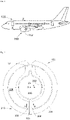
- the Fig. 1 shows an aircraft 100 which conventionally comprises a turbojet engine 150 which makes it possible to generate thrust to move said aircraft 100 forward.
- a turbojet engine 150 which makes it possible to generate thrust to move said aircraft 100 forward.
- thrust reversal modules 152 which are part of the turbojet 150 and which generate a reverse thrust to the forward direction of the aircraft 100 to slow it down.
- thrust reverser module 152 on the port side and one on the starboard side.
- the Fig. 2 is a schematic representation in front view of the thrust reverser modules 152.
- the turbojet 150 and the inversion modules 152 comprise a secondary stream 208 in which a secondary flow of air circulates from the front to the rear of the aircraft 100.
- Each inversion module 152 comprises inversion doors which are movably mounted on the structure of said inversion module 152 and which alternately assume a retracted position or a deployed position. In the retracted position, the reversing gates are not across the secondary stream 208 and do not obstruct the flow of the secondary flow. In the deployed position, the reversal gates are across the secondary stream 208 and obstruct the flow of secondary flow. The secondary flow is then directed outward and forward of the turbojet engine 150 to generate thrust slowing down the aircraft 100.
- Each inversion module 152 comprises an inner box 202 and an outer box 204.
- the boxes 202 and 204 each generally take the form of a half-cylinder centered on a longitudinal direction X of the inversion module 152 corresponding to a longitudinal direction of the 150 turbojet.
- the two inversion modules 152 are mounted articulated on a structure of the turbojet engine 150 and each inversion module 152 is rotatable around a horizontal axis 52 arranged in the upper part of the turbojet engine 150.
- the inner boxes 202 delimit an inner volume 206 in which the heart of the turbojet engine 150 is housed.
- the secondary stream 208 is delimited between each inner box 202 and the corresponding outer box 204.
- fixing systems 210 which extend radially with respect to the longitudinal direction X.
- a fastening system 210 which is placed at 6 o'clock in an area called the “lower bifurcation” and which overall takes the form of a beam extending in a vertical plane XZ.
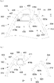
- the Fig. 3 shows a fastening system 210 of the state of the art in section along the line III-III of the Fig. 2 and in the secondary vein 208.
- the two inversion modules 152 are separated by a technician and the fixing system 210 opens in order to check the components which are housed in said fixing system 210.
- the system fixing 210 comprises a port cover 302 fixed between the inner box 202 and the outer box 204 of the reversal module 152 on the port side, and a starboard cover 304 fixed between the inner box 202 and the outer box 204 of the reversal module 152 to starboard.
- the port cowl 302 here has a leading edge 308 which faces the secondary flow and which is extended on one of its sides by a port side flank 310 extending towards the rear of the turbojet engine 150.
- the leading edge 308 here extends generally parallel to the vertical direction Z.
- the starboard cowl 304 here only has a starboard side 312.
- the starboard side 312 extends the leading edge 308 on the other of its sides, and a channel 314 is present between the port cowl 302 and the starboard side. 312.
- a seal 306 is provided, of the elastomer seal type, which is fixed to one of the cowls, here the port cowl 302, and against which the other cowl, here the starboard cowl 304 rests.
- the seal 306 is located in a housing 316 provided inside the fastening system 210, generally between the port side 310 and the starboard side 312.
- the housing 316 is in fluid communication with the channel 314.
- the joint 306 comprises a foot 307 and a bead 311 integral with the foot 307 and the fastening system 210 comprises a shoe 309 which is fixed to the port cowl 302 in a vertical plane XZ and in which the foot 307 is held.
- the foot 307 is thus fixed in a vertical plane XZ and the flange 311 projects from the foot 307 in a transverse direction Y which is perpendicular to the vertical plane XZ.
- the seal 306 provides the seal for fluids and fire between the interior of the fixing system 210 and the secondary vein 208. To complete this seal, it is known to make labyrinths using metal lamellae.
- the fastening system 210 here comprises a first slat 318 fixed to the inside of the port cowl 302 and a second slat 320 fixed to the inside of the starboard cowl 304.
- the two slats 318 and 320 are curved towards one another. another downstream of joint 306 with respect to channel 314.
- the forces s apply mainly parallel to the transverse direction Y.
- the seal therefore moves mainly in the transverse direction Y and it is necessary to provide a robust seal, that is to say having a large diameter in order to ensure sealing and its lifespan.
- An object of the present invention is to provide an aircraft turbojet engine comprising two thrust reverser modules and comprising a fixing system between an inner box and an outer box of each thrust reverser module, where the fixing system comprises a port cowl and a starboard cowl between which is arranged a seal which undergoes less deformation and where the effort required to tighten the cowls is reduced.
- the flange is mainly subjected to forces in the longitudinal direction. Consequently, the bead moves mainly in the longitudinal direction, thus limiting the movements in the transverse direction Y due to manufacturing and assembly tolerances and to movements in flight, also limiting the shearing at its base accordingly.
- This advantage makes it possible to reduce the diameter of the seal and therefore the forces to be applied when closing the covers.
- the fastening system further comprises a first elastic strip with a first end fixed in the housing to the first cover, a second free end projecting towards the second cover, and, between the first end and the second end, a flat zone generally parallel to the fixing wall, where the bead bears against the flat zone, and the crushing means is a thrust means secured to the second cover and arranged to move the flat zone towards the fixing wall when the second cowl passes from the separated position to the close position.
- the thrust means is a second slat with a first end fixed in the housing to the second cover, a second free end projecting towards the first cover and, between the first end and the second end, a zone plane generally parallel to the fixing wall, where in the separated position, the first slat is in a rest position, where the flat zone of the second slat is at or in front of the flat zone of the first slat, where in position close together, the first slat is in an active position in which it is close to the fixing wall with respect to the rest position, and the flat zone of the second slat is positioned behind and against the flat zone of the first slat with respect to in blood sausage.
- the second end of the first slat is curved towards the fixing wall and the second end of the second slat is curved away from the fixing wall.
- the thrust means is a second slat with a first end fixed in the housing to the second cover, a second free end projecting towards the first cover and towards the rear of the inversion module, and , between the first end and the second end, a flat zone which has an acute angle with respect to the fixing wall, where in the separated position, the first slat is in a rest position, where in the close position, the first slat is in an active position in which it is brought closer to the fixing wall with respect to the rest position, and where the flat zone of the second slat is positioned so as to come into contact with the second end of the first slat during the passage from the spread position to the close position.
- the second end of the first slat is curved towards the fixing wall.
- the crushing means is a lamella, one end of which is fixed in the housing inside the second wall of the second cover and one second end of which is free and projects towards the first wall of the first cover, the second end is curved away from the fixing wall, and in the separated position, the second end is positioned facing the flange.
- a plane of symmetry of the bead is offset towards the first cover with respect to a plane of symmetry of the foot.
- the invention also proposes an aircraft comprising a turbojet engine according to one of the preceding variants.
- Fig. 1 and the Fig. 2 are identical in the case of the invention and in the case of the state of the art, the only differences between the subject of the invention and the state of the art reside in the structure of the connection system and these differences are only visible in the section views which are shown in Figs. 4 and 5 for a first embodiment of the invention, to Figs. 6 and 7 for a second embodiment of the invention and to Figs. 8 and 9 for a third embodiment of the invention. Therefore, the elements common to the invention and to the state of the art bear the same references.
- the aircraft 100 comprises a turbojet engine 150 having two thrust reversal modules 152 which are equipped with means, such as reversing doors, making it possible to deflect the secondary flow towards the outside and towards the front of the turbojet engine 150 to slow down the aircraft 100.
- the movement of each thrust reverser module 152 is a rotation around a horizontal axis 52.
- the terms relating to a position are taken in reference to an aircraft in a normal flight position, that is to say as it is represented on the Fig. 1 and the “forward” and “rear” positions are taken relative to the front and rear of the turbojet engine and relative to the direction of advance of the aircraft 100 when the turbojet engine 152 is operating.
- X the longitudinal direction of the inversion modules which coincides with the longitudinal direction X of the turbojet and oriented towards the front of the aircraft
- Y the transverse direction which is horizontal when the aircraft is on the ground
- Z the vertical direction which is vertical when the aircraft is on the ground
- Each inversion module 152 comprises an inner box 202 and an outer box 204.
- the two boxes 202 and 204 each generally take the form of a half-cylinder centered on the longitudinal direction X of the inversion module 152.
- the inner box 202 is housed within outer box 204 and each box 202, 204 is attached to a structure of the inversion module 152.
- the structure of the inversion module 152 may be a part of either of the caissons 202, 204.
- the inner boxes 202 delimit an inner volume 206 in which the heart of the turbojet engine 150 is housed.
- the secondary stream 208 is delimited between each inner box 202 and the corresponding outer box 204.
- the inversion module 152 comprises a fastening system 400, 600, 800 which is shown in section in Figs. 4 to 9 and which ensures, for each inversion module 152, the fixing of the two boxes 202 and 204 to each other and in a concentric manner, that is to say from the inner box 202 to the outer box 204 of the module of inversion 152 considered.
- the Fig. 4 shows the 400 mounting system in close operating position and the Fig. 5 shows the fastening system 400 in the spread-open position for maintenance.
- the Fig. 6 shows the 600 mounting system in close operating position and the Fig. 7 shows the 600 clamping system in the spread-open position for maintenance.
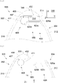
- the Fig. 8 shows the 800 mounting system in close operating position and the Fig. 9 shows the 800 clamping system in the spread-open position for maintenance.
- the two reversing modules 152 are moved aside by a technician and the fastening system 400, 600, 800 is opened ( Fig. 5 , Fig. 7 , Fig. 9 ), in order to check the components which are housed in said fixing system 400, 600, 800.
- the fixing system 400, 600, 800 comprises a first cover 302, here the cover port side in the figures, fixed between the inner box 202 and the outer box 204 of one of the inversion modules 152 here on the port side, and a second cover 304, here the starboard cover, fixed between the inner box 202 and the box exterior 204 of the other inversion module 152 here to starboard.
- the close position corresponds to the operating position ( Fig. 4 , Fig. 6 , Fig. 8 ) in which the first cover 302 and the second cover 304 are closest to each other, and the separated position corresponds to the maintenance position ( Fig. 5 , Fig. 7 , Fig. 9 ) in which the first cover 302 and the second cover 304 are furthest from each other.
- the second cover 304 is kept fixed in position on the structure by fixing means such as, for example, fasteners.
- the first cowl 302 has a leading edge 308 which faces the secondary flow which flows parallel to the longitudinal direction X in the secondary vein 208.
- the leading edge 308 is here generally parallel to the vertical direction Z.
- the second cowl 304 comprises a second flank 312 here to starboard which extends to the rear and on one of the sides of the leading edge 308 and the first cowl 302 has a first flank 310, here to port, integral with the leading edge 308 and which extends to the rear and on the other side of the leading edge 308.
- the first flank 310 extends the leading edge 308.
- the second flank 312 extends the leading edge 308 and a channel 314 is present between the first cowl 302 and the second flank 312.
- the first cover 302 and the second cover 304 define between them a housing 316.
- the first cowl 302 has, at the rear of the leading edge 308, a fixing wall 402 which extends perpendicularly to the longitudinal direction X, that is to say parallel to the plane YZ, and which partly delimits the housing 316 provided inside the fastening system 400, 600, 800 between the first cover 302 and the second cover 304 and in fluid communication with the channel 314.
- the fixing system 400, 600, 800 comprises a gasket 406, of the elastomer gasket type, which is fixed to the fixing wall 402 in the housing 316 between the first flank 310 and the second flank 312.
- the gasket 406 ensures the sealing for fluids and fire between the interior of the fastening system 400, 600, 800 and the secondary vein 208.
- the seal 406 comprises a foot 407 and a bead 411 integral with the foot 407.
- the seal 406 is fixed in the housing 316 to the fixing wall 402 via the foot 407 and, to this end, the fastening system 400, 600, 800 comprises a shoe 409 which is fixed to the fastening wall 402 and in which the foot 407 is maintained.
- the foot 407 is thus fixed in the vertical plane YZ perpendicular to the longitudinal direction X and the flange 411 projects rearwardly into the housing 316 from the foot 407 in the longitudinal direction X.
- the fixing system 400, 600, 800 comprises a crushing means 450, 650, 850 secured to the second cover 304 and arranged to crush the bead 411 towards the fixing wall 402 when the second cover 304 moves from the spread position to the close position.
- the fastening system 400, 600 also comprises a first elastic strip 418, in particular a metal spring strip, of which a first end 418a is fixed in the housing 316 inside the first wall 310 of the first cover 302 and of which a second end 418b is free and projects towards the second wall 312 of the second cover 304.
- a first elastic strip 418 in particular a metal spring strip
- the first slat 418 has a flat zone 418c which is generally parallel to the fixing wall 402.
- the seal 406 is arranged between the fixing wall 402 and the flat zone 418c and the bead 411 bears against the flat zone 418c of the first strip 418.
- the crushing means 450, 650 of the fixing system 400, 600 comprises a pushing means 420, 620 which is integral with the second cover 304 and which is arranged to move the flat zone 418c towards the fixing wall 402 when the second cover 304 passes from the separated position to the close position, that is to say when the second cowl 304 moves globally parallel to the transverse direction Y due to the dimensions of the turbojet engine 150.
- the action of the thrust means 420, 620 on the first lamella 418 tends to elastically deform said first lamella 418, in particular at the level of the junction between the first end 418a and the flat zone 418c.
- the flat zone 418c moves mainly parallel to the longitudinal direction X, and the bead 411 is also compressed along the longitudinal direction X. Even if during its movement, the second cover 304 has parasitic movements parallel to the longitudinal direction X , these displacements are added to the displacements generated by the thrust means 420, 620 which are in the same direction and there is then no cutting force perpendicular to the longitudinal direction X at the junction zone of the flange 411 on the foot 407 and thus the seal 406 is preserved.
- the seal 406 may have a reduced size since it is only stressed in the longitudinal direction, in fact independent of the transverse direction Y in which the manufacturing and assembly tolerances apply as well as the movements in flight. , which facilitates the transition to the close position.
- the first slat 418 In the separated position, the first slat 418 is in a rest position and is subjected to the pressure exerted by the bead 411
- the first strip 418 is in an active position in which it is close to the fixing wall 402 with respect to the rest position and compresses the bead 411.
- the thrust means 420 takes the form of a second elastic or rigid strip 420, in particular for example a metal strip, of which a first end 420a is fixed in the housing 316 inside the second wall 312 of the second cover 304 and of which a second end 420b is free and projects towards the first wall 310 of the first cover 302.
- the second strip 420 has a flat zone 420c which is generally parallel to the wall of fixing 402.
- the second slat 420 When the second slat 420 is elastic and in the separated position, it is in a rest position and the flat zone 420c of the second slat 420 is positioned at or in front of the flat zone 418c of the first slat 418. In close position , the second slat 420 is in an active position in which it is away from the fixing wall 402 with respect to the rest position and the flat zone 420c of the second slat 420 is positioned behind and against the flat zone 418c of the first slat 418 with respect to the bead 411.
- the flat zone 420c of the second slat 420 comes from behind into contact with the flat zone 418c of the first slat 418 and the second slat 420 moves back towards its active position while pushing the first slat 418 forward which advances towards its active position.
- the second slat 420 When the second slat 420 is rigid, it remains in the same position, where in the separated position, the flat zone 420c of the second slat 420 is at or in front of the flat zone 418c of the first slat 418, and where in position close together, the flat zone 420c of the second slat 420 is positioned behind and against the flat zone 418c of the first slat 418 with respect to the flange 411 and pushes the first slat 418 forwards which advances towards its active position.
- the second end 418b of the first slat 418 is curved towards the attachment wall 402 and the second end 420b of the second slat 420 is curved away from the attachment wall 402.
- the two curved ends 418b and 420b slide one over the other to move the slats 418 and 420 from their rest positions to their active positions.
- the thrust means 620 also takes the form of a second elastic or rigid strip 620, in particular for example a metal strip, of which a first end 620a is fixed in the housing 316 inside the second wall 312 of the second cover 304 and of which a second end 620b is free and projects towards the first wall 310 of the first cover 302 and towards the rear of the inversion module 152.
- the second strip 420 has a flat zone 620c which has an acute angle with respect to the fixing wall 402. According to a particular embodiment, the angle is for example greater than 0° and less than 70°.
- the second lamella 620 When the second lamella 620 is elastic and in the separated position, it is in a rest position and in the close position, the second lamella 620 is in an active position with an angle relative to the fixing wall 402 which is smaller than in the rest position.
- the flat zone 620c of the second slat 620 is positioned so as to come into contact with the second end 418b of the first slat 418 when passing from the separated position to the close position.
- the flat zone 620c of the second slat 620 comes into contact with the second end 418b of the first slat 418 and due to the acute angle, the flat zone 620c pushes the first slat 418 forwards which advances towards its active position.
- the second slat 420 When the second slat 420 is rigid, it remains in the same position, and the flat zone 620c of the second slat 620 is positioned so as to come into contact with the second end 418b of the first slat 418 when passing from the separated position in the close position.
- the second end 418b of the first slat 418 is curved towards the fixing wall 402.
- the slats 418, 420, 620 also make it possible to create labyrinths which complete the tightness of the seal 406.
- the crushing means 850 of the fixing system 800 takes the form of an elastic strip 820 or rigid, in particular for example a metal blade, of which a first end 820a is fixed in the housing 316 inside the second wall 312 of the second cover 304 and of which a second end 820b is free and projects towards the first wall 310 of the first cover 302.
- the slat 820 has a flat zone 820c which is generally parallel to the fixing wall 402 and the second end 820b is curved at the opposite the fixing wall 402.
- the second end 820b is positioned opposite the flange 411 parallel to the transverse direction Y, and preferably between the middle and the rear of the flange 411.
- the second end 820b comes into contact with the bead 411 and it compresses said bead 411 in a plane depending on the X and Y components.
- the behavior and the integrity of the bead 411 are ensured by the fact that it rolls during the compression by the second end 820b.
- the slat 800 therefore bears against the flange 411 and provides fluid and fire tightness.
- the size of the joint 406 is reduced because the adjustment tolerances of the locks are no longer to be considered in their entirety because the component in X reduces the component in Y and the force necessary for closing the covers is reduced.
- the plane of symmetry of the bead 411 which is parallel to the XZ plane is offset towards the first cover 302 parallel to the transverse direction Y with respect to the plane of symmetry of the foot 407 parallel to the XZ plane.
Landscapes
- Engineering & Computer Science (AREA)
- Chemical & Material Sciences (AREA)
- Combustion & Propulsion (AREA)
- Mechanical Engineering (AREA)
- General Engineering & Computer Science (AREA)
- Aviation & Aerospace Engineering (AREA)
- Structures Of Non-Positive Displacement Pumps (AREA)
- Turbine Rotor Nozzle Sealing (AREA)
Abstract
Description
- La présente invention concerne un turboréacteur d'aéronef comportant deux modules d'inversion de poussée et un système de fixation entre deux caissons de chaque module, ainsi qu'un aéronef comportant un tel turboréacteur.
- La
Fig. 1 montre un aéronef 100 qui comporte classiquement un turboréacteur 150 qui permet de générer une poussée pour faire avancer ledit aéronef 100. Lorsque l'aéronef 100 doit freiner, il est connu d'utiliser des modules d'inversion de poussée 152 qui font partie du turboréacteur 150 et qui génèrent une poussée inverse à la direction d'avancement de l'aéronef 100 pour le ralentir. Il y a un module d'inversion de poussée 152 à bâbord et un à tribord. - La
Fig. 2 est une représentation schématique en vue de face des modules d'inversion de poussée 152. - Le turboréacteur 150 et les modules d'inversion 152 comportent une veine secondaire 208 dans laquelle, un flux secondaire d'air circule de l'avant vers l'arrière de l'aéronef 100.
- Chaque module d'inversion 152 comporte des portes d'inversion qui sont montées mobiles sur la structure dudit module d'inversion 152 et qui prennent alternativement une position escamotée ou une position déployée. En position escamotée, les portes d'inversion ne sont pas en travers de la veine secondaire 208 et ne font pas obstacle à l'écoulement du flux secondaire. En position déployée, les portes d'inversion sont en travers de la veine secondaire 208 et font obstacle à l'écoulement du flux secondaire. Le flux secondaire est alors dirigé vers l'extérieur et vers l'avant du turboréacteur 150 pour générer une poussée ralentissant l'aéronef 100.
- Chaque module d'inversion 152 comporte un caisson intérieur 202 et un caisson extérieur 204. Les caissons 202 et 204 prennent chacun globalement la forme d'un demi-cylindre centré sur une direction longitudinale X du module d'inversion 152 correspondant à une direction longitudinale du turboréacteur 150.
- Pour des raisons de maintenance, les deux modules d'inversion 152 sont montés articulés sur une structure du turboréacteur 150 et chaque module d'inversion 152 est mobile en rotation autour d'un axe horizontal 52 disposé en partie haute du turboréacteur 150.
- Les caissons intérieurs 202 délimitent un volume intérieur 206 dans lequel est logé le cœur du turboréacteur 150. La veine secondaire 208 est délimitée entre chaque caisson intérieur 202 et le caisson extérieur 204 correspondant.
- Afin de fixer les deux caissons 202 et 204 l'un à l'autre et de manière concentrique, il est connu de disposer des systèmes de fixation 210 qui s'étendent radialement par rapport à la direction longitudinale X. En particulier, il est connu d'utiliser un système de fixation 210 qui est disposé à 6 heures dans une zone appelée « bifurcation inférieure » et qui prend globalement la forme d'une poutre s'étendant dans un plan vertical XZ.
- La
Fig. 3 montre un système de fixation 210 de l'état de la technique en coupe selon la ligne III-III de laFig. 2 et dans la veine secondaire 208. - Lors de la maintenance du turboréacteur 150, les deux modules d'inversion 152 sont écartés par un technicien et le système de fixation 210 s'ouvre afin de vérifier les composants qui sont logés dans ledit système de fixation 210. À cette fin, le système de fixation 210 comporte un capot bâbord 302 fixé entre le caisson intérieur 202 et le caisson extérieur 204 du module d'inversion 152 à bâbord, et un capot tribord 304 fixé entre le caisson intérieur 202 et le caisson extérieur 204 du module d'inversion 152 à tribord.
- En position de fonctionnement (
Fig. 3 ), le capot tribord 304 et le capot bâbord 302 sont maintenus l'un contre l'autre. - Le capot bâbord 302 présente ici un bord d'attaque 308 qui fait face au flux secondaire et qui se prolonge sur l'un de ses côtés par un flanc bâbord 310 s'étendant vers l'arrière du turboréacteur 150. Le bord d'attaque 308 s'étend ici globalement parallèlement à la direction verticale Z.
- Le capot tribord 304 comporte ici uniquement un flanc tribord 312.
- Lorsque le capot bâbord 302 et le capot tribord 304 sont en position de fonctionnement, le flanc tribord 312 prolonge le bord d'attaque 308 sur l'autre de ses côtés, et un canal 314 est présent entre le capot bâbord 302 et le flanc tribord 312.
- Pour assurer la jonction des deux capots 302 et 304, il est prévu un joint 306, du type joint en élastomère, qui est fixé à l'un des capots, ici le capot bâbord 302, et contre lequel l'autre capot, ici le capot tribord 304 vient en appui.
- Le joint 306 se trouve dans un logement 316 ménagé à l'intérieur du système de fixation 210, globalement entre le flanc bâbord 310 et le flanc tribord 312. Le logement 316 est en communication fluidique avec le canal 314.
- Le joint 306 comporte un pied 307 et un boudin 311 solidaire du pied 307 et le système de fixation 210 comporte un sabot 309 qui est fixé au capot bâbord 302 dans un plan vertical XZ et dans lequel le pied 307 est maintenu. Le pied 307 est ainsi fixé dans un plan vertical XZ et le boudin 311 se projette depuis le pied 307 selon une direction transversale Y qui est perpendiculaire au plan vertical XZ.
- Le joint 306 assure l'étanchéité pour les fluides et le feu entre l'intérieur du système de fixation 210 et la veine secondaire 208. Pour compléter cette étanchéité, il est connu de réaliser des labyrinthes à l'aide de lamelles métalliques.
- Le système de fixation 210 comporte ici, une première lamelle 318 fixée à l'intérieur du capot bâbord 302 et une deuxième lamelle 320 fixée à l'intérieur du capot tribord 304. Les deux lamelles 318 et 320 sont courbées l'une vers l'autre en aval du joint 306 par rapport au canal 314.
- Du fait des tolérances de fabrication et de montage des modules d'inversion 152 sur la structure du turboréacteur 150 et du fait des déplacements en vol du capot bâbord 302 et du capot tribord 304 l'un par rapport à l'autre, les efforts s'appliquent principalement parallèlement à la direction transversale Y. Le joint se déplace donc principalement selon la direction transversale Y et il est nécessaire de prévoir un joint robuste, c'est-à-dire présentant un diamètre important afin d'assurer l'étanchéité et sa durée de vie.
- Cette robustesse du joint nécessite des efforts importants pour fermer les capots et il est donc souhaitable de trouver un nouvel arrangement pour le système de fixation.
- Un objet de la présente invention est de proposer un turboréacteur d'aéronef comportant deux modules d'inversion de poussée et comportant un système de fixation entre un caisson intérieur et un caisson extérieur de chaque module d'inversion de poussée, où le système de fixation comporte un capot bâbord et un capot tribord entre lesquels est disposé un joint qui subit moins de déformation et où l'effort nécessaire au serrage des capots est réduit.
- À cet effet, est proposé un turboréacteur d'un aéronef présentant une direction longitudinale et une direction transversale perpendiculaire à la direction longitudinale et comportant :
- une structure,
- deux modules d'inversion de poussée montés articulés sur la structure entre une position rapprochée et une position écartée,
- un système de fixation assurant, pour chaque module d'inversion de poussée, la fixation du caisson intérieur au caisson extérieur, et comportant :
- un premier capot fixé entre le caisson intérieur et le caisson extérieur de l'un des modules d'inversion, et présentant un bord d'attaque,
- un deuxième capot fixé entre le caisson intérieur et le caisson extérieur de l'autre des modules d'inversion,
- un joint comportant un pied et un boudin solidaire du pied, où le pied est fixé dans le logement à la paroi de fixation et où le boudin se projette depuis le pied selon la direction longitudinale, et
- Avec un tel arrangement, le boudin subit principalement des efforts selon la direction longitudinale. En conséquence, le boudin se déplace principalement selon la direction longitudinale, limitant ainsi les déplacements selon la direction transversale Y dus aux tolérances de fabrication et de montage et aux déplacements en vol, limitant également d'autant les cisaillements au niveau de son pied. Cet avantage permet de réduire le diamètre du joint et donc les efforts à appliquer lors de la fermeture des capots.
- Selon un mode de réalisation particulier, le système de fixation comporte en outre, une première lamelle élastique avec une première extrémité fixée dans le logement au premier capot, une deuxième extrémité libre et se projetant vers le deuxième capot, et, entre la première extrémité et la deuxième extrémité, une zone plane globalement parallèle à la paroi de fixation, où le boudin est en appui contre la zone plane, et le moyen d'écrasement est un moyen de poussée solidaire du deuxième capot et agencé pour déplacer la zone plane vers la paroi de fixation lorsque le deuxième capot passe de la position écartée à la position rapprochée.
- Selon un mode de réalisation particulier, le moyen de poussée est une deuxième lamelle avec une première extrémité fixée dans le logement au deuxième capot, une deuxième extrémité libre se projetant vers le premier capot et, entre la première extrémité et la deuxième extrémité, une zone plane globalement parallèle à la paroi de fixation, où en position écartée, la première lamelle est dans une position de repos, où la zone plane de la deuxième lamelle est au niveau ou en avant de la zone plane de la première lamelle, où en position rapprochée, la première lamelle est dans une position active dans laquelle elle est rapprochée de la paroi de fixation par rapport à la position de repos, et la zone plane de la deuxième lamelle est positionnée derrière et contre la zone plane de la première lamelle par rapport au boudin.
- Avantageusement, la deuxième extrémité de la première lamelle est courbée vers la paroi de fixation et la deuxième extrémité de la deuxième lamelle est courbée à l'opposé de la paroi de fixation.
- Selon un autre mode de réalisation particulier, le moyen de poussée est une deuxième lamelle avec une première extrémité fixée dans le logement au deuxième capot, une deuxième extrémité libre se projetant vers le premier capot et vers l'arrière du module d'inversion, et, entre la première extrémité et la deuxième extrémité, une zone plane qui présente un angle aigu par rapport à la paroi de fixation, où en position écartée, la première lamelle est dans une position de repos, où en position rapprochée, la première lamelle est dans une position active dans laquelle elle est rapprochée de la paroi de fixation par rapport à la position de repos, et où la zone plane de la deuxième lamelle est positionnée de manière à entrer en contact avec la deuxième extrémité de la première lamelle lors du passage de la position écartée à la position rapprochée.
- Avantageusement, la deuxième extrémité de la première lamelle est courbée vers la paroi de fixation.
- Selon un mode de réalisation particulier, le moyen d'écrasement est une lamelle dont une première extrémité est fixée dans le logement à l'intérieur de la deuxième paroi du deuxième capot et dont une deuxième extrémité est libre et se projette vers la première paroi du premier capot, la deuxième extrémité est courbée à l'opposé de la paroi de fixation, et en position écartée, la deuxième extrémité se positionne en regard du boudin.
- Avantageusement, un plan de symétrie du boudin est décalé vers le premier capot par rapport à un plan de symétrie du pied.
- L'invention propose également un aéronef comportant un turboréacteur selon l'une des variantes précédentes.
- Les caractéristiques de l'invention mentionnées ci-dessus, ainsi que d'autres, apparaîtront plus clairement à la lecture de la description suivante d'un exemple de réalisation, ladite description étant faite en relation avec les dessins joints, parmi lesquels :
-
Fig. 1 est une vue de côté d'un aéronef, -
Fig. 2 est une représentation schématique en vue de face des modules d'inversion d'un turboréacteur, -
Fig. 3 est une vue en coupe selon la ligne III-III de laFig. 2 , d'un système de fixation de l'état de la technique, -
Fig. 4 montre une vue similaire à la vue de laFig. 3 pour un système de fixation selon un premier mode de réalisation de l'invention, -
Fig. 5 montre le système de fixation de laFig. 4 en position ouverte, -
Fig. 6 montre une vue similaire à la vue de laFig. 3 pour un système de fixation selon un deuxième mode de réalisation de l'invention, -
Fig. 7 montre le système de fixation de laFig. 6 en position ouverte, -
Fig. 8 montre une vue similaire à la vue de laFig. 3 pour un système de fixation selon un troisième mode de réalisation de l'invention, et -
Fig. 9 montre le système de fixation de laFig. 8 en position ouverte. - La
Fig. 1 et laFig. 2 sont identiques dans le cas de l'invention et dans le cas de l'état de la technique, les seules différences entre l'objet de l'invention et l'état de la technique résident dans la structure du système de liaison et ces différences ne sont visibles que dans les vues en coupe qui sont représentées auxFigs. 4 et 5 pour un premier mode de réalisation de l'invention, auxFigs. 6 et 7 pour un deuxième mode de réalisation de l'invention et auxFigs. 8 et 9 pour un troisième mode de réalisation de l'invention. De ce fait, les éléments communs à l'invention et à l'état de la technique portent les mêmes références. - L'aéronef 100 comporte un turboréacteur 150 présentant deux modules d'inversion de poussée 152 qui sont équipés de moyens, tels que des portes d'inversion, permettant de dévier le flux secondaire vers l'extérieur et vers l'avant du turboréacteur 150 pour ralentir l'aéronef 100. Il y a un module d'inversion de poussée 152 à bâbord et un à tribord qui sont montés articulés sur une structure du turboréacteur 150 entre une position rapprochée de vol et une position écartée pour maintenance. Le déplacement de chaque module d'inversion de poussée 152 est une rotation autour d'un axe horizontal 52.
- Dans la description qui suit, les termes relatifs à une position sont pris en référence à un aéronef en position normale de vol, c'est-à-dire comme il est représenté sur la
Fig. 1 et les positions « avant » et « arrière » sont prises par rapport à l'avant et l'arrière du turboréacteur et par rapport à la direction d'avancement de l'aéronef 100 lorsque le turboréacteur 152 fonctionne. - Dans la description qui suit, et par convention, on appelle X la direction longitudinale des modules d'inversion qui est confondue avec la direction longitudinale X du turboréacteur et orientée vers l'avant de l'aéronef, on appelle Y la direction transversale qui est horizontale lorsque l'aéronef est au sol, et Z la direction verticale qui est verticale lorsque l'aéronef est au sol, ces trois directions X, Y et Z étant orthogonales entre elles.
- Chaque module d'inversion 152 comporte un caisson intérieur 202 et un caisson extérieur 204. Les deux caissons 202 et 204 prennent chacun globalement la forme d'un demi-cylindre centré sur la direction longitudinale X du module d'inversion 152. Le caisson intérieur 202 est logé à l'intérieur du caisson extérieur 204 et chaque caisson 202, 204 est fixé à une structure du module d'inversion 152. La structure du module d'inversion 152 peut être une partie de l'un ou l'autre des caissons 202, 204.
- Les caissons intérieurs 202 délimitent un volume intérieur 206 dans lequel est logé le cœur du turboréacteur 150. La veine secondaire 208 est délimitée entre chaque caisson intérieur 202 et le caisson extérieur 204 correspondant.
- Au niveau de la bifurcation inférieure, le module d'inversion 152 comporte un système de fixation 400, 600, 800 qui est représenté en coupe aux
Figs. 4 à 9 et qui assure, pour chaque module d'inversion 152, la fixation des deux caissons 202 et 204 l'un à l'autre et de manière concentrique, c'est-à-dire du caisson intérieur 202 au caisson extérieur 204 du module d'inversion 152 considéré. - La
Fig. 4 montre le système de fixation 400 en position rapprochée de fonctionnement et laFig. 5 montre le système de fixation 400 en position écartée ouverte pour maintenance. - La
Fig. 6 montre le système de fixation 600 en position rapprochée de fonctionnement et laFig. 7 montre le système de fixation 600 en position écartée ouverte pour maintenance. - La
Fig. 8 montre le système de fixation 800 en position rapprochée de fonctionnement et laFig. 9 montre le système de fixation 800 en position écartée ouverte pour maintenance. - Lors de la maintenance du turboréacteur 150, les deux modules d'inversion 152 sont écartés par un technicien et le système de fixation 400, 600, 800 est ouvert (
Fig. 5 ,Fig. 7 ,Fig. 9 ), afin de vérifier les composants qui sont logés dans ledit système de fixation 400, 600, 800. À cette fin, le système de fixation 400, 600, 800 comporte un premier capot 302, ici le capot bâbord sur les figures, fixé entre le caisson intérieur 202 et le caisson extérieur 204 de l'un des modules d'inversion 152 ici à bâbord, et un deuxième capot 304, ici le capot tribord, fixé entre le caisson intérieur 202 et le caisson extérieur 204 de l'autre module d'inversion 152 ici à tribord. - La position rapprochée correspond à la position de fonctionnement (
Fig. 4 ,Fig. 6 ,Fig. 8 ) dans laquelle le premier capot 302 et le deuxième capot 304 sont au plus près l'un de l'autre, et la position écartée correspond à la position de maintenance (Fig. 5 ,Fig. 7 ,Fig. 9 ) dans laquelle le premier capot 302 et le deuxième capot 304 sont au plus loin l'un de l'autre. En position de fonctionnement, le deuxième capot 304 est maintenu fixé en position sur la structure par des moyens de fixation comme par exemple des éléments de visserie. - Comme pour l'état de la technique, le premier capot 302 présente un bord d'attaque 308 qui fait face au flux secondaire qui s'écoule parallèlement à la direction longitudinale X dans la veine secondaire 208. Le bord d'attaque 308 est ici globalement parallèle à la direction verticale Z.
- Le deuxième capot 304 comporte un deuxième flanc 312 ici à tribord qui s'étend à l'arrière et sur l'un des côtés du bord d'attaque 308 et le premier capot 302 présente un premier flanc 310, ici à bâbord, solidaire du bord d'attaque 308 et qui s'étend à l'arrière et sur l'autre des côtés du bord d'attaque 308. Le premier flanc 310 prolonge le bord d'attaque 308.
- Lorsque le premier capot 302 et le deuxième capot 304 sont en position de fonctionnement, le deuxième flanc 312 prolonge le bord d'attaque 308 et un canal 314 est présent entre le premier capot 302 et le deuxième flanc 312.
- En position rapprochée, le premier capot 302 et le deuxième capot 304 délimitent entre eux un logement 316.
- Le premier capot 302 présente à l'arrière du bord d'attaque 308, une paroi de fixation 402 qui s'étend perpendiculairement à la direction longitudinale X, c'est-à-dire parallèle au plan YZ, et qui délimite en partie le logement 316 ménagé à l'intérieur du système de fixation 400, 600, 800 entre le premier capot 302 et le deuxième capot 304 et en communication fluidique avec le canal 314.
- Le système de fixation 400, 600, 800 comporte un joint 406, du type joint en élastomère, qui est fixé à la paroi de fixation 402 dans le logement 316 entre le premier flanc 310 et le deuxième flanc 312. Le joint 406 assure l'étanchéité pour les fluides et le feu entre l'intérieur du système de fixation 400, 600, 800 et la veine secondaire 208.
- À cette fin, le joint 406 comporte un pied 407 et un boudin 411 solidaire du pied 407. Le joint 406 est fixé dans le logement 316 à la paroi de fixation 402 par l'intermédiaire du pied 407 et, à cette fin, le système de fixation 400, 600, 800 comporte un sabot 409 qui est fixé à la paroi de fixation 402 et dans lequel le pied 407 est maintenu.
- Le pied 407 est ainsi fixé dans le plan vertical YZ perpendiculaire à la direction longitudinale X et le boudin 411 se projette vers l'arrière dans le logement 316 depuis le pied 407 selon la direction longitudinale X.
- Dans chacun des modes de réalisation, le système de fixation 400, 600, 800 comporte un moyen d'écrasement 450, 650, 850 solidaire du deuxième capot 304 et agencé pour écraser le boudin 411 vers la paroi de fixation 402 lorsque le deuxième capot 304 passe de la position écartée à la position rapprochée.
- Dans le premier et le deuxième modes de réalisation présentés aux
Figs. 4 à 7 , le système de fixation 400, 600 comporte également une première lamelle 418 élastique, en particulier une lame ressort métallique, dont une première extrémité 418a est fixée dans le logement 316 à l'intérieur de la première paroi 310 du premier capot 302 et dont une deuxième extrémité 418b est libre et se projette vers la deuxième paroi 312 du deuxième capot 304. Entre la première extrémité 418a et la deuxième extrémité 418b, la première lamelle 418 présente une zone plane 418c qui est globalement parallèle à la paroi de fixation 402. - Ainsi, selon la direction longitudinale X, le joint 406 est disposé entre la paroi de fixation 402 et la zone plane 418c et le boudin 411 est en appui contre la zone plane 418c de la première lamelle 418.
- Le moyen d'écrasement 450, 650 du système de fixation 400, 600 comporte un moyen de poussée 420, 620 qui est solidaire du deuxième capot 304 et qui est agencé pour déplacer la zone plane 418c vers la paroi de fixation 402 lorsque le deuxième capot 304 passe de la position écartée à la position rapprochée, c'est-à-dire lorsque le deuxième capot 304 se déplace globalement parallèlement à la direction transversale Y du fait des dimensions du turboréacteur 150. L'action du moyen de poussée 420, 620 sur la première lamelle 418 tend à déformer de manière élastique ladite première lamelle 418, en particulier au niveau de la jonction entre la première extrémité 418a et la zone plane 418c.
- Ainsi, la zone plane 418c se déplace principalement parallèlement à la direction longitudinale X, et le boudin 411 est également comprimé selon la direction longitudinale X. Même si lors de son déplacement, le deuxième capot 304 présente des déplacements parasites parallèlement à la direction longitudinale X, ces déplacements s'ajoutent aux déplacements engendrés par le moyen de poussée 420, 620 qui sont dans la même direction et il n'y a alors aucun effort de sectionnement perpendiculairement à la direction longitudinale X au niveau de la zone de jonction du boudin 411 sur le pied 407 et ainsi le joint 406 est préservé.
- En outre, le joint 406 peut avoir une taille réduite puisqu'il n'est sollicité que selon la direction longitudinale, de fait indépendante de la direction transversale Y selon laquelle s'appliquent les tolérances de fabrication et de montage ainsi que les déplacements en vol, ce qui facilite le passage vers la position rapprochée.
- En position écartée, la première lamelle 418 est dans une position de repos et est soumise à la pression exercée par le boudin 411
- En position rapprochée, la première lamelle 418 est dans une position active dans laquelle elle est rapprochée de la paroi de fixation 402 par rapport à la position de repos et comprime le boudin 411.
- Dans le mode de réalisation de l'invention de la
Fig. 4 et de laFig. 5 , le moyen de poussée 420 prend la forme d'une deuxième lamelle 420 élastique ou rigide, en particulier par exemple une lame métallique, dont une première extrémité 420a est fixée dans le logement 316 à l'intérieur de la deuxième paroi 312 du deuxième capot 304 et dont une deuxième extrémité 420b est libre et se projette vers la première paroi 310 du premier capot 302. Entre la première extrémité 420a et la deuxième extrémité 420b, la deuxième lamelle 420 présente une zone plane 420c qui est globalement parallèle à la paroi de fixation 402. - Lorsque la deuxième lamelle 420 est élastique et en position écartée, elle est dans une position de repos et la zone plane 420c de la deuxième lamelle 420 se positionne au niveau ou en avant de la zone plane 418c de la première lamelle 418. En position rapprochée, la deuxième lamelle 420 est dans une position active dans laquelle elle est éloignée de la paroi de fixation 402 par rapport à la position de repos et la zone plane 420c de la deuxième lamelle 420 est positionnée derrière et contre la zone plane 418c de la première lamelle 418 par rapport au boudin 411. Ainsi, lorsque le deuxième capot 304 se rapproche du premier capot 302, la zone plane 420c de la deuxième lamelle 420 vient par derrière au contact de la zone plane 418c de la première lamelle 418 et la deuxième lamelle 420 recule vers sa position active tout en poussant la première lamelle 418 vers l'avant qui avance vers sa position active.
- Lorsque la deuxième lamelle 420 est rigide, elle reste dans la même position, où en position écartée, la zone plane 420c de la deuxième lamelle 420 est au niveau ou en avant de la zone plane 418c de la première lamelle 418, et où en position rapprochée, la zone plane 420c de la deuxième lamelle 420 est positionnée derrière et contre la zone plane 418c de la première lamelle 418 par rapport au boudin 411 et pousse la première lamelle 418 vers l'avant qui avance vers sa position active.
- Pour faciliter le passage de la deuxième lamelle 420 derrière la première lamelle 418 lors du passage de la position écartée à la position rapprochée, la deuxième extrémité 418b de la première lamelle 418 est courbée vers la paroi de fixation 402 et la deuxième extrémité 420b de la deuxième lamelle 420 est courbée à l'opposé de la paroi de fixation 402. Ainsi, lors du déplacement de la position écartée à la position rapprochée, les deux extrémités courbées 418b et 420b glissent l'une sur l'autre pour déplacer les lamelles 418 et 420 de leurs positions de repos vers leurs positions actives.
- Dans le mode de réalisation de l'invention des
Figs. 6 et 7 , le moyen de poussée 620 prend également la forme d'une deuxième lamelle 620 élastique ou rigide, en particulier par exemple une lame métallique, dont une première extrémité 620a est fixée dans le logement 316 à l'intérieur de la deuxième paroi 312 du deuxième capot 304 et dont une deuxième extrémité 620b est libre et se projette vers la première paroi 310 du premier capot 302 et vers l'arrière du module d'inversion 152. Entre la première extrémité 620a et la deuxième extrémité 620b, la deuxième lamelle 420 présente une zone plane 620c qui présente un angle aigu par rapport à la paroi de fixation 402. Selon un mode de réalisation particulier, l'angle est par exemple supérieur à 0° et inférieur à 70°. - Lorsque la deuxième lamelle 620 est élastique et en position écartée, elle est dans une position de repos et en position rapprochée, la deuxième lamelle 620 est dans une position active avec un angle par rapport à la paroi de fixation 402 qui est moins grand que dans la position de repos. La zone plane 620c de la deuxième lamelle 620 est positionnée de manière à entrer en contact avec la deuxième extrémité 418b de la première lamelle 418 lors du passage de la position écartée à la position rapprochée. Ainsi, lorsque le deuxième capot 304 se rapproche du premier capot 302, la zone plane 620c de la deuxième lamelle 620 vient au contact de la deuxième extrémité 418b de la première lamelle 418 et du fait de l'angle aigu, la zone plane 620c pousse la première lamelle 418 vers l'avant qui avance vers sa position active.
- Lorsque la deuxième lamelle 420 est rigide, elle reste dans la même position, et la zone plane 620c de la deuxième lamelle 620 est positionnée de manière à entrer en contact avec la deuxième extrémité 418b de la première lamelle 418 lors du passage de la position écartée à la position rapprochée.
- Pour faciliter le glissement de la deuxième extrémité 418b de la première lamelle 418 sur la zone plane 620c de la deuxième lamelle 620, la deuxième extrémité 418b de la première lamelle 418 est courbée vers la paroi de fixation 402.
- Les lamelles 418, 420, 620 permettent en outre de créer des labyrinthes qui complètent l'étanchéité du joint 406.
- Dans le troisième mode de réalisation de l'invention présenté aux
Figs. 8 et 9 , le moyen d'écrasement 850 du système de fixation 800 prend la forme d'une lamelle 820 élastique ou rigide, en particulier par exemple une lame métallique, dont une première extrémité 820a est fixée dans le logement 316 à l'intérieur de la deuxième paroi 312 du deuxième capot 304 et dont une deuxième extrémité 820b est libre et se projette vers la première paroi 310 du premier capot 302. - Dans le mode de réalisation de l'invention présenté ici, entre la première extrémité 820a et la deuxième extrémité 820b, la lamelle 820 présente une zone plane 820c qui est globalement parallèle à la paroi de fixation 402 et la deuxième extrémité 820b est courbée à l'opposé de la paroi de fixation 402.
- En position écartée, la deuxième extrémité 820b se positionne en regard du boudin 411 parallèlement à la direction transversale Y, et préférentiellement entre le milieu et l'arrière du boudin 411.
- En position rapprochée, la deuxième extrémité 820b arrive au contact du boudin 411 et elle comprime ledit boudin 411 dans un plan dépendant des composantes X et Y. Le comportement et l'intégrité du boudin 411 sont assurés du fait qu'il roule lors de la compression par la deuxième extrémité 820b. En positon rapprochée, la lamelle 800 vient donc en appui contre le boudin 411 et assure l'étanchéité au fluide et au feu.
- Comme pour les autres modes de réalisation, la taille du joint 406 est réduite car les tolérances de réglages des verrous ne sont plus à considérer en totalité du fait que la composante en X réduit la composante en Y et l'effort nécessaire à la fermeture des capots est réduit.
- Dans le mode de réalisation de l'invention présenté sur les
Figs. 8 et 9 , le plan de symétrie du boudin 411 qui est parallèle au plan XZ est décalé vers le premier capot 302 parallèlement à la direction transversale Y par rapport au plan de symétrie du pied 407 parallèle au plan XZ.
Claims (9)
- Turboréacteur (150) d'aéronef (100) présentant une direction longitudinale (X) et une direction transversale (Y) perpendiculaire à la direction longitudinale (X) et comportant :- une structure,- deux modules d'inversion de poussée (152) montés articulés sur la structure entre une position rapprochée et une position écartée,où chaque module d'inversion de poussée (152) comporte un caisson extérieur (204) prenant globalement la forme d'un demi-cylindre centré sur la direction longitudinale (X), un caisson intérieur (202) prenant globalement la forme d'un demi-cylindre centré sur la direction longitudinale (X), logé à l'intérieur du caisson extérieur (204), et- un système de fixation (400, 600, 800) assurant, pour chaque module d'inversion de poussée (152), la fixation du caisson intérieur (202) au caisson extérieur (204), et comportant :- un premier capot (302) fixé entre le caisson intérieur (202) et le caisson extérieur (204) de l'un des modules d'inversion (152), et présentant un bord d'attaque (308),- un deuxième capot (304) fixé entre le caisson intérieur (202) et le caisson extérieur (204) de l'autre des modules d'inversion (152),où un logement (316) est ménagé entre le premier capot (302) et le deuxième capot (304) et délimité par une paroi de fixation (402) du premier capot (302) s'étendant perpendiculairement à la direction longitudinale (X) à l'arrière du bord d'attaque (308),- un joint (406) comportant un pied (407) et un boudin (411) solidaire du pied (407) où le pied (407) est fixé dans le logement (316) à la paroi de fixation (402) et où le boudin (411) se projette depuis le pied (407) selon la direction longitudinale (X), et- un moyen d'écrasement (450, 650, 850) solidaire du deuxième capot (304) et agencé pour écraser le boudin (411) vers la paroi de fixation (402) lorsque le deuxième capot (304) passe de la position écartée à la position rapprochée.
- Turboréacteur (150) selon la revendication 1, caractérisé en ce que le système de fixation (400, 600) comporte en outre, une première lamelle (418) élastique avec une première extrémité (418a) fixée dans le logement (316) au premier capot (302), une deuxième extrémité (418b) libre et se projetant vers le deuxième capot (304), et, entre la première extrémité (418a) et la deuxième extrémité (418b), une zone plane (418c) globalement parallèle à la paroi de fixation (402), où le boudin (411) est en appui contre la zone plane (418c), et en ce que le moyen d'écrasement (450, 650) est un moyen de poussée (420, 620) solidaire du deuxième capot (304) et agencé pour déplacer la zone plane (418c) vers la paroi de fixation (402) lorsque le deuxième capot (304) passe de la position écartée à la position rapprochée.
- Turboréacteur (150) selon la revendication 2, caractérisé en ce que le moyen de poussée (420) est une deuxième lamelle (420) avec une première extrémité (420a) fixée dans le logement (316) au deuxième capot (304), une deuxième extrémité (420b) libre se projetant vers le premier capot (302) et, entre la première extrémité (420a) et la deuxième extrémité (420b), une zone plane (420c) globalement parallèle à la paroi de fixation (402), où en position écartée, la première lamelle (418) est dans une position de repos, où la zone plane (420c) de la deuxième lamelle (420) est au niveau ou en avant de la zone plane (418c) de la première lamelle (418), où en position rapprochée, la première lamelle (418) est dans une position active dans laquelle elle est rapprochée de la paroi de fixation (402) par rapport à la position de repos, et la zone plane (420c) de la deuxième lamelle (420) est positionnée derrière et contre la zone plane (418c) de la première lamelle (418) par rapport au boudin (411).
- Turboréacteur (150) selon la revendication 3, caractérisé en ce que la deuxième extrémité (418b) de la première lamelle (418) est courbée vers la paroi de fixation (402) et la deuxième extrémité (420b) de la deuxième lamelle (420) est courbée à l'opposé de la paroi de fixation (402).
- Turboréacteur (150) selon la revendication 2, caractérisé en ce que le moyen de poussée (620) est une deuxième lamelle (620) avec une première extrémité (620a) fixée dans le logement (316) au deuxième capot (304), une deuxième extrémité (620b) libre se projetant vers le premier capot (302) et vers l'arrière du module d'inversion (152), et, entre la première extrémité (620a) et la deuxième extrémité (620b), une zone plane (620c) qui présente un angle aigu par rapport à la paroi de fixation (402), où en position écartée, la première lamelle (418) est dans une position de repos, où en position rapprochée, la première lamelle (418) est dans une position active dans laquelle elle est rapprochée de la paroi de fixation (402) par rapport à la position de repos, et où la zone plane (620c) de la deuxième lamelle (620) est positionnée de manière à entrer en contact avec la deuxième extrémité (418b) de la première lamelle (418) lors du passage de la position écartée à la position rapprochée.
- Turboréacteur (150) selon la revendication 5, caractérisé en ce que la deuxième extrémité (418b) de la première lamelle (418) est courbée vers la paroi de fixation (402).
- Turboréacteur (150) selon la revendication 1, caractérisé en ce que le moyen d'écrasement (850) est une lamelle (820) dont une première extrémité (820a) est fixée dans le logement (316) à l'intérieur de la deuxième paroi (312) du deuxième capot (304) et dont une deuxième extrémité (820b) est libre et se projette vers la première paroi (310) du premier capot (302), en ce que la deuxième extrémité (820b) est courbée à l'opposé de la paroi de fixation (402), et en ce qu'en position écartée, la deuxième extrémité (820b) se positionne en regard du boudin (411).
- Turboréacteur (150) selon la revendication 7, caractérisé en ce qu'un plan de symétrie du boudin (411) est décalé vers le premier capot (302) par rapport à un plan de symétrie du pied (407).
- Aéronef (10) comportant un turboréacteur (150) selon l'une des revendications précédentes.
Applications Claiming Priority (1)
| Application Number | Priority Date | Filing Date | Title |
|---|---|---|---|
| FR2100470A FR3118997A1 (fr) | 2021-01-19 | 2021-01-19 | Turboréacteur d’aéronef comportant deux modules d’inversion de poussée |
Publications (2)
| Publication Number | Publication Date |
|---|---|
| EP4029783A1 true EP4029783A1 (fr) | 2022-07-20 |
| EP4029783B1 EP4029783B1 (fr) | 2023-12-20 |
Family
ID=75339887
Family Applications (1)
| Application Number | Title | Priority Date | Filing Date |
|---|---|---|---|
| EP22151601.6A Active EP4029783B1 (fr) | 2021-01-19 | 2022-01-14 | Turboréacteur d'aéronef comportant deux modules d'inversion de poussée |
Country Status (3)
| Country | Link |
|---|---|
| US (1) | US11692511B2 (fr) |
| EP (1) | EP4029783B1 (fr) |
| FR (1) | FR3118997A1 (fr) |
Families Citing this family (1)
| Publication number | Priority date | Publication date | Assignee | Title |
|---|---|---|---|---|
| CN118518252A (zh) * | 2023-02-17 | 2024-08-20 | 空中客车运营简化股份公司 | 压力测量耙、包括压力测量耙的发动机和包括发动机的飞行器 |
Citations (4)
| Publication number | Priority date | Publication date | Assignee | Title |
|---|---|---|---|---|
| US20170362957A1 (en) * | 2016-06-17 | 2017-12-21 | Rohr, Inc. | Nacelle with bifurcation extension and integral structural reinforcement |
| US20180156131A1 (en) * | 2016-12-07 | 2018-06-07 | Rohr, Inc. | Sealing cooling inner fixed structure |
| EP3628597A1 (fr) * | 2018-09-26 | 2020-04-01 | The Boeing Company | Systèmes d'étanchéité à utiliser dans un aéronef |
| US20210003097A1 (en) * | 2018-03-19 | 2021-01-07 | Safran Nacelles | Bypass propulsion unit, comprising a thrust reverser with movable cascades |
Family Cites Families (1)
| Publication number | Priority date | Publication date | Assignee | Title |
|---|---|---|---|---|
| US10570764B2 (en) * | 2016-04-01 | 2020-02-25 | Rohr, Inc. | Bulb seal and spring |
-
2021
- 2021-01-19 FR FR2100470A patent/FR3118997A1/fr not_active Ceased
-
2022
- 2022-01-14 EP EP22151601.6A patent/EP4029783B1/fr active Active
- 2022-01-14 US US17/575,686 patent/US11692511B2/en active Active
Patent Citations (4)
| Publication number | Priority date | Publication date | Assignee | Title |
|---|---|---|---|---|
| US20170362957A1 (en) * | 2016-06-17 | 2017-12-21 | Rohr, Inc. | Nacelle with bifurcation extension and integral structural reinforcement |
| US20180156131A1 (en) * | 2016-12-07 | 2018-06-07 | Rohr, Inc. | Sealing cooling inner fixed structure |
| US20210003097A1 (en) * | 2018-03-19 | 2021-01-07 | Safran Nacelles | Bypass propulsion unit, comprising a thrust reverser with movable cascades |
| EP3628597A1 (fr) * | 2018-09-26 | 2020-04-01 | The Boeing Company | Systèmes d'étanchéité à utiliser dans un aéronef |
Also Published As
| Publication number | Publication date |
|---|---|
| US11692511B2 (en) | 2023-07-04 |
| EP4029783B1 (fr) | 2023-12-20 |
| US20220228540A1 (en) | 2022-07-21 |
| FR3118997A1 (fr) | 2022-07-22 |
Similar Documents
| Publication | Publication Date | Title |
|---|---|---|
| EP0471596B1 (fr) | Dispositif d'étanchéité à joint gonflable pour porte ou panneau mobile | |
| FR2663671A1 (fr) | Systeme d'articulation de panneaux et application aux portes sectionnelles. | |
| EP1563147B1 (fr) | Dispositif pour accoupler des pieces d'usure aux outils receptacles d'un engin de travaux publics | |
| CA2180402C (fr) | Inverseur de poussee de turboreacteur a une coquille | |
| EP3483069B1 (fr) | Systeme d'attache moteur d'aeronef | |
| CA2239462C (fr) | Inverseur de poussee de turboreacteur a portes munies d'un becquet mobile a entrainement optimise | |
| EP4029783B1 (fr) | Turboréacteur d'aéronef comportant deux modules d'inversion de poussée | |
| EP0654598B1 (fr) | Inverseur de poussée de turboreacteur à double flux | |
| CA2185300A1 (fr) | Inverseur de poussee de turboreacteur a portes associees a un panneau primaire | |
| EP3647202A1 (fr) | Ensemble turbomachine d'aeronef comportant un capot articule | |
| FR2651021A1 (fr) | Inverseur de poussee de turboreacteur, a portes associees a un panneau amont | |
| EP3719293A1 (fr) | Turboréacteur comportant une nacelle équipée d'un système inverseur et une grille de cascades mobile | |
| WO1998040618A1 (fr) | Inverseur de poussee de turboreacteur a portes a structure externe plaquee | |
| FR2684051A1 (fr) | Dispositif d'etancheite pour panneaux transparents affleurant sur une carrosserie de vehicule. | |
| FR3107091A1 (fr) | Dispositif de fixation d’un pied de bielle de volet d’inversion de poussée à grilles | |
| EP1625322A1 (fr) | Raccord rapide pour conduites de fluide hydraulique | |
| FR2807879A1 (fr) | Conduit de cablage electrique a charniere souple | |
| EP2516778B1 (fr) | Dispositif d'obturation et ensemble correspondant | |
| CA2022439C (fr) | Inverseur de poussee de turboreacteur, a portes associees a un panneau amont | |
| EP3462967B1 (fr) | Dispositif de connexion pour sangles, objets, parties de vêtements et accessoires | |
| EP3341231B1 (fr) | Porte de véhicule automobile comprenant deux joints reliés entre eux | |
| FR3068080A1 (fr) | Nacelle d'aeronef comportant un volet inverseur et un joint | |
| FR2770575A1 (fr) | Dispositif d'etancheite anti-effraction pour vitrage coulissant | |
| FR2911924A1 (fr) | Dispositif de filtre a air et systeme d'admission comportant un tel dispositif | |
| EP3526461B1 (fr) | Deflecteur de liquide de refroidissement |
Legal Events
| Date | Code | Title | Description |
|---|---|---|---|
| PUAI | Public reference made under article 153(3) epc to a published international application that has entered the european phase |
Free format text: ORIGINAL CODE: 0009012 |
|
| STAA | Information on the status of an ep patent application or granted ep patent |
Free format text: STATUS: THE APPLICATION HAS BEEN PUBLISHED |
|
| AK | Designated contracting states |
Kind code of ref document: A1 Designated state(s): AL AT BE BG CH CY CZ DE DK EE ES FI FR GB GR HR HU IE IS IT LI LT LU LV MC MK MT NL NO PL PT RO RS SE SI SK SM TR |
|
| STAA | Information on the status of an ep patent application or granted ep patent |
Free format text: STATUS: REQUEST FOR EXAMINATION WAS MADE |
|
| 17P | Request for examination filed |
Effective date: 20230116 |
|
| RBV | Designated contracting states (corrected) |
Designated state(s): AL AT BE BG CH CY CZ DE DK EE ES FI FR GB GR HR HU IE IS IT LI LT LU LV MC MK MT NL NO PL PT RO RS SE SI SK SM TR |
|
| GRAP | Despatch of communication of intention to grant a patent |
Free format text: ORIGINAL CODE: EPIDOSNIGR1 |
|
| STAA | Information on the status of an ep patent application or granted ep patent |
Free format text: STATUS: GRANT OF PATENT IS INTENDED |
|
| INTG | Intention to grant announced |
Effective date: 20230711 |
|
| GRAS | Grant fee paid |
Free format text: ORIGINAL CODE: EPIDOSNIGR3 |
|
| GRAA | (expected) grant |
Free format text: ORIGINAL CODE: 0009210 |
|
| STAA | Information on the status of an ep patent application or granted ep patent |
Free format text: STATUS: THE PATENT HAS BEEN GRANTED |
|
| AK | Designated contracting states |
Kind code of ref document: B1 Designated state(s): AL AT BE BG CH CY CZ DE DK EE ES FI FR GB GR HR HU IE IS IT LI LT LU LV MC MK MT NL NO PL PT RO RS SE SI SK SM TR |
|
| REG | Reference to a national code |
Ref country code: GB Ref legal event code: FG4D Free format text: NOT ENGLISH |
|
| REG | Reference to a national code |
Ref country code: DE Ref legal event code: R096 Ref document number: 602022001308 Country of ref document: DE |
|
| REG | Reference to a national code |
Ref country code: CH Ref legal event code: EP |
|
| REG | Reference to a national code |
Ref country code: IE Ref legal event code: FG4D Free format text: LANGUAGE OF EP DOCUMENT: FRENCH |
|
| PG25 | Lapsed in a contracting state [announced via postgrant information from national office to epo] |
Ref country code: GR Free format text: LAPSE BECAUSE OF FAILURE TO SUBMIT A TRANSLATION OF THE DESCRIPTION OR TO PAY THE FEE WITHIN THE PRESCRIBED TIME-LIMIT Effective date: 20240321 |
|
| REG | Reference to a national code |
Ref country code: LT Ref legal event code: MG9D |
|
| PG25 | Lapsed in a contracting state [announced via postgrant information from national office to epo] |
Ref country code: LT Free format text: LAPSE BECAUSE OF FAILURE TO SUBMIT A TRANSLATION OF THE DESCRIPTION OR TO PAY THE FEE WITHIN THE PRESCRIBED TIME-LIMIT Effective date: 20231220 |
|
| REG | Reference to a national code |
Ref country code: NL Ref legal event code: MP Effective date: 20231220 |
|
| PG25 | Lapsed in a contracting state [announced via postgrant information from national office to epo] |
Ref country code: ES Free format text: LAPSE BECAUSE OF FAILURE TO SUBMIT A TRANSLATION OF THE DESCRIPTION OR TO PAY THE FEE WITHIN THE PRESCRIBED TIME-LIMIT Effective date: 20231220 |
|
| PG25 | Lapsed in a contracting state [announced via postgrant information from national office to epo] |
Ref country code: LT Free format text: LAPSE BECAUSE OF FAILURE TO SUBMIT A TRANSLATION OF THE DESCRIPTION OR TO PAY THE FEE WITHIN THE PRESCRIBED TIME-LIMIT Effective date: 20231220 Ref country code: GR Free format text: LAPSE BECAUSE OF FAILURE TO SUBMIT A TRANSLATION OF THE DESCRIPTION OR TO PAY THE FEE WITHIN THE PRESCRIBED TIME-LIMIT Effective date: 20240321 Ref country code: FI Free format text: LAPSE BECAUSE OF FAILURE TO SUBMIT A TRANSLATION OF THE DESCRIPTION OR TO PAY THE FEE WITHIN THE PRESCRIBED TIME-LIMIT Effective date: 20231220 Ref country code: ES Free format text: LAPSE BECAUSE OF FAILURE TO SUBMIT A TRANSLATION OF THE DESCRIPTION OR TO PAY THE FEE WITHIN THE PRESCRIBED TIME-LIMIT Effective date: 20231220 Ref country code: BG Free format text: LAPSE BECAUSE OF FAILURE TO SUBMIT A TRANSLATION OF THE DESCRIPTION OR TO PAY THE FEE WITHIN THE PRESCRIBED TIME-LIMIT Effective date: 20240320 |
|
| REG | Reference to a national code |
Ref country code: AT Ref legal event code: MK05 Ref document number: 1642273 Country of ref document: AT Kind code of ref document: T Effective date: 20231220 |
|
| PG25 | Lapsed in a contracting state [announced via postgrant information from national office to epo] |
Ref country code: NL Free format text: LAPSE BECAUSE OF FAILURE TO SUBMIT A TRANSLATION OF THE DESCRIPTION OR TO PAY THE FEE WITHIN THE PRESCRIBED TIME-LIMIT Effective date: 20231220 |
|
| PG25 | Lapsed in a contracting state [announced via postgrant information from national office to epo] |
Ref country code: SE Free format text: LAPSE BECAUSE OF FAILURE TO SUBMIT A TRANSLATION OF THE DESCRIPTION OR TO PAY THE FEE WITHIN THE PRESCRIBED TIME-LIMIT Effective date: 20231220 Ref country code: RS Free format text: LAPSE BECAUSE OF FAILURE TO SUBMIT A TRANSLATION OF THE DESCRIPTION OR TO PAY THE FEE WITHIN THE PRESCRIBED TIME-LIMIT Effective date: 20231220 Ref country code: NO Free format text: LAPSE BECAUSE OF FAILURE TO SUBMIT A TRANSLATION OF THE DESCRIPTION OR TO PAY THE FEE WITHIN THE PRESCRIBED TIME-LIMIT Effective date: 20240320 Ref country code: NL Free format text: LAPSE BECAUSE OF FAILURE TO SUBMIT A TRANSLATION OF THE DESCRIPTION OR TO PAY THE FEE WITHIN THE PRESCRIBED TIME-LIMIT Effective date: 20231220 Ref country code: LV Free format text: LAPSE BECAUSE OF FAILURE TO SUBMIT A TRANSLATION OF THE DESCRIPTION OR TO PAY THE FEE WITHIN THE PRESCRIBED TIME-LIMIT Effective date: 20231220 Ref country code: HR Free format text: LAPSE BECAUSE OF FAILURE TO SUBMIT A TRANSLATION OF THE DESCRIPTION OR TO PAY THE FEE WITHIN THE PRESCRIBED TIME-LIMIT Effective date: 20231220 |
|
| PG25 | Lapsed in a contracting state [announced via postgrant information from national office to epo] |
Ref country code: IS Free format text: LAPSE BECAUSE OF FAILURE TO SUBMIT A TRANSLATION OF THE DESCRIPTION OR TO PAY THE FEE WITHIN THE PRESCRIBED TIME-LIMIT Effective date: 20240420 |
|
| PG25 | Lapsed in a contracting state [announced via postgrant information from national office to epo] |
Ref country code: CZ Free format text: LAPSE BECAUSE OF FAILURE TO SUBMIT A TRANSLATION OF THE DESCRIPTION OR TO PAY THE FEE WITHIN THE PRESCRIBED TIME-LIMIT Effective date: 20231220 Ref country code: AT Free format text: LAPSE BECAUSE OF FAILURE TO SUBMIT A TRANSLATION OF THE DESCRIPTION OR TO PAY THE FEE WITHIN THE PRESCRIBED TIME-LIMIT Effective date: 20231220 |
|
| PG25 | Lapsed in a contracting state [announced via postgrant information from national office to epo] |
Ref country code: SK Free format text: LAPSE BECAUSE OF FAILURE TO SUBMIT A TRANSLATION OF THE DESCRIPTION OR TO PAY THE FEE WITHIN THE PRESCRIBED TIME-LIMIT Effective date: 20231220 |
|
| PG25 | Lapsed in a contracting state [announced via postgrant information from national office to epo] |
Ref country code: SM Free format text: LAPSE BECAUSE OF FAILURE TO SUBMIT A TRANSLATION OF THE DESCRIPTION OR TO PAY THE FEE WITHIN THE PRESCRIBED TIME-LIMIT Effective date: 20231220 Ref country code: SK Free format text: LAPSE BECAUSE OF FAILURE TO SUBMIT A TRANSLATION OF THE DESCRIPTION OR TO PAY THE FEE WITHIN THE PRESCRIBED TIME-LIMIT Effective date: 20231220 Ref country code: RO Free format text: LAPSE BECAUSE OF FAILURE TO SUBMIT A TRANSLATION OF THE DESCRIPTION OR TO PAY THE FEE WITHIN THE PRESCRIBED TIME-LIMIT Effective date: 20231220 Ref country code: IT Free format text: LAPSE BECAUSE OF FAILURE TO SUBMIT A TRANSLATION OF THE DESCRIPTION OR TO PAY THE FEE WITHIN THE PRESCRIBED TIME-LIMIT Effective date: 20231220 Ref country code: IS Free format text: LAPSE BECAUSE OF FAILURE TO SUBMIT A TRANSLATION OF THE DESCRIPTION OR TO PAY THE FEE WITHIN THE PRESCRIBED TIME-LIMIT Effective date: 20240420 Ref country code: EE Free format text: LAPSE BECAUSE OF FAILURE TO SUBMIT A TRANSLATION OF THE DESCRIPTION OR TO PAY THE FEE WITHIN THE PRESCRIBED TIME-LIMIT Effective date: 20231220 Ref country code: CZ Free format text: LAPSE BECAUSE OF FAILURE TO SUBMIT A TRANSLATION OF THE DESCRIPTION OR TO PAY THE FEE WITHIN THE PRESCRIBED TIME-LIMIT Effective date: 20231220 Ref country code: AT Free format text: LAPSE BECAUSE OF FAILURE TO SUBMIT A TRANSLATION OF THE DESCRIPTION OR TO PAY THE FEE WITHIN THE PRESCRIBED TIME-LIMIT Effective date: 20231220 |
|
| PG25 | Lapsed in a contracting state [announced via postgrant information from national office to epo] |
Ref country code: PL Free format text: LAPSE BECAUSE OF FAILURE TO SUBMIT A TRANSLATION OF THE DESCRIPTION OR TO PAY THE FEE WITHIN THE PRESCRIBED TIME-LIMIT Effective date: 20231220 Ref country code: PT Free format text: LAPSE BECAUSE OF FAILURE TO SUBMIT A TRANSLATION OF THE DESCRIPTION OR TO PAY THE FEE WITHIN THE PRESCRIBED TIME-LIMIT Effective date: 20240422 |
|
| PG25 | Lapsed in a contracting state [announced via postgrant information from national office to epo] |
Ref country code: PT Free format text: LAPSE BECAUSE OF FAILURE TO SUBMIT A TRANSLATION OF THE DESCRIPTION OR TO PAY THE FEE WITHIN THE PRESCRIBED TIME-LIMIT Effective date: 20240422 Ref country code: PL Free format text: LAPSE BECAUSE OF FAILURE TO SUBMIT A TRANSLATION OF THE DESCRIPTION OR TO PAY THE FEE WITHIN THE PRESCRIBED TIME-LIMIT Effective date: 20231220 |
|
| PG25 | Lapsed in a contracting state [announced via postgrant information from national office to epo] |
Ref country code: LU Free format text: LAPSE BECAUSE OF NON-PAYMENT OF DUE FEES Effective date: 20240114 |
|
| REG | Reference to a national code |
Ref country code: DE Ref legal event code: R097 Ref document number: 602022001308 Country of ref document: DE |
|
| PG25 | Lapsed in a contracting state [announced via postgrant information from national office to epo] |
Ref country code: LU Free format text: LAPSE BECAUSE OF NON-PAYMENT OF DUE FEES Effective date: 20240114 Ref country code: MC Free format text: LAPSE BECAUSE OF FAILURE TO SUBMIT A TRANSLATION OF THE DESCRIPTION OR TO PAY THE FEE WITHIN THE PRESCRIBED TIME-LIMIT Effective date: 20231220 |
|
| PG25 | Lapsed in a contracting state [announced via postgrant information from national office to epo] |
Ref country code: DK Free format text: LAPSE BECAUSE OF FAILURE TO SUBMIT A TRANSLATION OF THE DESCRIPTION OR TO PAY THE FEE WITHIN THE PRESCRIBED TIME-LIMIT Effective date: 20231220 |
|
| PG25 | Lapsed in a contracting state [announced via postgrant information from national office to epo] |
Ref country code: BE Free format text: LAPSE BECAUSE OF NON-PAYMENT OF DUE FEES Effective date: 20240131 |
|
| PLBE | No opposition filed within time limit |
Free format text: ORIGINAL CODE: 0009261 |
|
| STAA | Information on the status of an ep patent application or granted ep patent |
Free format text: STATUS: NO OPPOSITION FILED WITHIN TIME LIMIT |
|
| PG25 | Lapsed in a contracting state [announced via postgrant information from national office to epo] |
Ref country code: SI Free format text: LAPSE BECAUSE OF FAILURE TO SUBMIT A TRANSLATION OF THE DESCRIPTION OR TO PAY THE FEE WITHIN THE PRESCRIBED TIME-LIMIT Effective date: 20231220 |
|
| PG25 | Lapsed in a contracting state [announced via postgrant information from national office to epo] |
Ref country code: SI Free format text: LAPSE BECAUSE OF FAILURE TO SUBMIT A TRANSLATION OF THE DESCRIPTION OR TO PAY THE FEE WITHIN THE PRESCRIBED TIME-LIMIT Effective date: 20231220 Ref country code: DK Free format text: LAPSE BECAUSE OF FAILURE TO SUBMIT A TRANSLATION OF THE DESCRIPTION OR TO PAY THE FEE WITHIN THE PRESCRIBED TIME-LIMIT Effective date: 20231220 Ref country code: BE Free format text: LAPSE BECAUSE OF NON-PAYMENT OF DUE FEES Effective date: 20240131 |
|
| REG | Reference to a national code |
Ref country code: BE Ref legal event code: MM Effective date: 20240131 |
|
| 26N | No opposition filed |
Effective date: 20240923 |
|
| PG25 | Lapsed in a contracting state [announced via postgrant information from national office to epo] |
Ref country code: IE Free format text: LAPSE BECAUSE OF NON-PAYMENT OF DUE FEES Effective date: 20240114 |
|
| PG25 | Lapsed in a contracting state [announced via postgrant information from national office to epo] |
Ref country code: IE Free format text: LAPSE BECAUSE OF NON-PAYMENT OF DUE FEES Effective date: 20240114 |
|
| PG25 | Lapsed in a contracting state [announced via postgrant information from national office to epo] |
Ref country code: CY Free format text: LAPSE BECAUSE OF FAILURE TO SUBMIT A TRANSLATION OF THE DESCRIPTION OR TO PAY THE FEE WITHIN THE PRESCRIBED TIME-LIMIT; INVALID AB INITIO Effective date: 20220114 |
|
| REG | Reference to a national code |
Ref country code: CH Ref legal event code: PL |
|
| PG25 | Lapsed in a contracting state [announced via postgrant information from national office to epo] |
Ref country code: CH Free format text: LAPSE BECAUSE OF NON-PAYMENT OF DUE FEES Effective date: 20250131 |
|
| PG25 | Lapsed in a contracting state [announced via postgrant information from national office to epo] |
Ref country code: TR Free format text: LAPSE BECAUSE OF FAILURE TO SUBMIT A TRANSLATION OF THE DESCRIPTION OR TO PAY THE FEE WITHIN THE PRESCRIBED TIME-LIMIT Effective date: 20231220 |
|
| PGFP | Annual fee paid to national office [announced via postgrant information from national office to epo] |
Ref country code: GB Payment date: 20260123 Year of fee payment: 5 |
|
| PGFP | Annual fee paid to national office [announced via postgrant information from national office to epo] |
Ref country code: DE Payment date: 20260121 Year of fee payment: 5 |
|
| PGFP | Annual fee paid to national office [announced via postgrant information from national office to epo] |
Ref country code: FR Payment date: 20260123 Year of fee payment: 5 |