EP4029754B1 - Verfahren zur herstellung eines ultraschnellen transportkomplexes - Google Patents
Verfahren zur herstellung eines ultraschnellen transportkomplexes Download PDFInfo
- Publication number
- EP4029754B1 EP4029754B1 EP20862498.1A EP20862498A EP4029754B1 EP 4029754 B1 EP4029754 B1 EP 4029754B1 EP 20862498 A EP20862498 A EP 20862498A EP 4029754 B1 EP4029754 B1 EP 4029754B1
- Authority
- EP
- European Patent Office
- Prior art keywords
- wall
- superspeed
- internal
- sealed evacuated
- tunnel
- Prior art date
- Legal status (The legal status is an assumption and is not a legal conclusion. Google has not performed a legal analysis and makes no representation as to the accuracy of the status listed.)
- Active
Links
Images





Classifications
-
- E—FIXED CONSTRUCTIONS
- E01—CONSTRUCTION OF ROADS, RAILWAYS, OR BRIDGES
- E01B—PERMANENT WAY; PERMANENT-WAY TOOLS; MACHINES FOR MAKING RAILWAYS OF ALL KINDS
- E01B25/00—Tracks for special kinds of railways
-
- B—PERFORMING OPERATIONS; TRANSPORTING
- B29—WORKING OF PLASTICS; WORKING OF SUBSTANCES IN A PLASTIC STATE IN GENERAL
- B29D—PRODUCING PARTICULAR ARTICLES FROM PLASTICS OR FROM SUBSTANCES IN A PLASTIC STATE
- B29D23/00—Producing tubular articles
- B29D23/001—Pipes; Pipe joints
-
- E—FIXED CONSTRUCTIONS
- E01—CONSTRUCTION OF ROADS, RAILWAYS, OR BRIDGES
- E01B—PERMANENT WAY; PERMANENT-WAY TOOLS; MACHINES FOR MAKING RAILWAYS OF ALL KINDS
- E01B2/00—General structure of permanent way
- E01B2/003—Arrangement of tracks on bridges or in tunnels
-
- E—FIXED CONSTRUCTIONS
- E01—CONSTRUCTION OF ROADS, RAILWAYS, OR BRIDGES
- E01B—PERMANENT WAY; PERMANENT-WAY TOOLS; MACHINES FOR MAKING RAILWAYS OF ALL KINDS
- E01B25/00—Tracks for special kinds of railways
- E01B25/30—Tracks for magnetic suspension or levitation vehicles
- E01B25/305—Rails or supporting constructions
-
- F—MECHANICAL ENGINEERING; LIGHTING; HEATING; WEAPONS; BLASTING
- F16—ENGINEERING ELEMENTS AND UNITS; GENERAL MEASURES FOR PRODUCING AND MAINTAINING EFFECTIVE FUNCTIONING OF MACHINES OR INSTALLATIONS; THERMAL INSULATION IN GENERAL
- F16L—PIPES; JOINTS OR FITTINGS FOR PIPES; SUPPORTS FOR PIPES, CABLES OR PROTECTIVE TUBING; MEANS FOR THERMAL INSULATION IN GENERAL
- F16L9/00—Rigid pipes
- F16L9/02—Rigid pipes of metal
- F16L9/04—Reinforced pipes
- F16L9/047—Reinforced pipes comprising reinforcement rings
-
- F—MECHANICAL ENGINEERING; LIGHTING; HEATING; WEAPONS; BLASTING
- F16—ENGINEERING ELEMENTS AND UNITS; GENERAL MEASURES FOR PRODUCING AND MAINTAINING EFFECTIVE FUNCTIONING OF MACHINES OR INSTALLATIONS; THERMAL INSULATION IN GENERAL
- F16L—PIPES; JOINTS OR FITTINGS FOR PIPES; SUPPORTS FOR PIPES, CABLES OR PROTECTIVE TUBING; MEANS FOR THERMAL INSULATION IN GENERAL
- F16L9/00—Rigid pipes
- F16L9/08—Rigid pipes of concrete, cement, or asbestos cement, with or without reinforcement
- F16L9/085—Reinforced pipes
-
- B—PERFORMING OPERATIONS; TRANSPORTING
- B29—WORKING OF PLASTICS; WORKING OF SUBSTANCES IN A PLASTIC STATE IN GENERAL
- B29D—PRODUCING PARTICULAR ARTICLES FROM PLASTICS OR FROM SUBSTANCES IN A PLASTIC STATE
- B29D23/00—Producing tubular articles
- B29D23/001—Pipes; Pipe joints
- B29D23/003—Pipe joints, e.g. straight joints
Definitions
- the present invention is related to the field of superspeed transport (speed more than 700 km/h), in particular - to main-line transport systems for transportation of passengers and goods, which provide movement of vehicle along track structure in overpass of closed type.
- a subway-type transport system which represents a tunnel with a rail cord of track structure and suitable vehicles located therein [1].
- Supersonic above-ground transport system by Yansufin comprising a vehicle with cars equipped at the bottom with a linear motor rotor, super electromagnets and super-permanent magnets.
- the cars are equipped with doors opening outwards.
- vacuum pumps adjusted for automatic operation are installed on the main pipe, and wind turbines are installed on top of the main pipe, mainly at the joints of separate pipes.
- a superfast transport system is also known, wherein the rail track is located on a closed reinforced concrete overpass in above ground or underground position.
- the cars represent the fuselage of the aircraft, and for the lateral stability of the cars on the curved sections of the rail track above the cars in the overpass, a special rail is provided, grabbed by rollers mounted on the roof of the cars.
- the rail track at the beginning of the movement is directed downhill, which, when moving back, is uphill and helps to carry out more effective braking at the end of the track; for the same purpose, the air is sucked from the overpass on the side of the destination station and pumped on the side of the departure station [3].
- the transport system of the above construction does not make full use of the possibilities to reduce the drag of the air flow at higher speeds of the proposed vehicle, in addition, a significant drawback of the above transport system is the limitation in smoothness and softness of travel due to the lack of flatness and straightness of the track structure, which does not allow to develop high speeds.
- the Hyperloop transport system is known, which includes an overhead pipeline located on supports, inside which single transport capsules move. Special guides located in the nose of the transport capsule and ventilator redirect the oncoming air flow under the bottom, which allows to create air cushion under the capsule in forevacuum conditions.
- the capsule is driven by a linear electric motor, wherein the stator is an aluminum rail, installed in the pipeline at a certain interval. Rotor is located in each capsule. Since the stator performs not only acceleration, but also deceleration, in the latter case the kinetic energy of the capsule is also converted to electric [4].
- each multilayer pipe contains connected to each other internal protective layer made of wear-resistant material, intermediate layer and external protective layer made of composite material, as well as flanges for connecting to adjacent pipes or pipe fittings. Internal protective layer and intermediate layer are attached to each other.
- Intermediate layer is made of polymer concrete reinforced with longitudinal rods rigidly attached with flanges into reinforcing frames [5].
- a method of constructing a highway for high-speed electric freight and passenger transport is known, according to which extended reinforced concrete overpasses with rails laid on longitudinal and transverse girders are erected on piles.
- the main line is passed through tunnels and equipped with platforms for passengers and power transmission line pylons [8].
- a transport complex with the said track structure ensures its high carrying capacity, however, significant material and labor intensity with low processability and penalized efficiency of the construction process of such transport complex, caused by the design of the track structure, as well as the difficulty of transportation to the installation site of large-sized extended span structures in the form of solid pipes of large diameter and their installation in the field with a complex landscape, and their limited possibilities for covering large spans between adjacent intermediate supports - are the restraining factors of the widespread use of such transport complexes.
- the aim of the invention is to attain the following technical object:
- the technical aim according to the object of the invention is achieved by a method of manufacturing of superspeed transport complex by Yunitski, whereby supports are installed on foundation; made and fastened in spans between them, is at least one trussed overpass (prestressed by tensioning in longitudinal direction) in the form of a longitudinal trussed track structure of string type for self-powered vehicle; annular frames are formed and fixed on trussed overpass transversely to trussed track structure; internal and external rows of load-bearing elements (tensioned in longitudinal direction) are arranged and fixed on inner and outer surfaces of annular frames, respectively; internal and external layers are formed, of at least one sealed evacuated tunnel with annular cross-section profile of its wall made of hardening composition, by applying it on the internal and external rows of load-bearing elements respectively and filling the space between the formed internal and external layers of the sealed evacuated tunnel with the hardening material of the intermediate
- the design of the superspeed transport complex by Yunitski manufactured per the method in accordance with the proposed technical approach which includes mounted in spans between supports, located on the foundation, at least one trussed string track structure of overpass type; with at least one self-powered vehicle mounted thereon; connected to at least one tunneled track structure including a sealed evacuated tunnel with an annular cross-section profile of its wall; consisting of internal, external and intermediate layers, and at least one rail cord located in sealed evacuated tunnel, intended for superspeed vehicle with a body providing sealing of the cabin during movement and a power unit, wherein the wall of the sealed evacuated tunnel is equipped with annular frames connected to each of the layers of the wall; and its internal and external layers are made of hardening composition and reinforced with prestressed by tensioning in longitudinal direction corresponding load-bearing elements; which are fastened to the inner and outer surfaces of the annular frames, respectively; and wherein the intermediate layer of the wall is made of a hardening material filling the space between
- the hardening material of the intermediate layer of the wall of the sealed evacuated tunnel contains load-bearing elements of the intermediate layer prestressed by tensioning in longitudinal direction up to the nominal design force and fastened on the annular frames.
- Tackling of this problem is guaranteed also under condition that concrete is used as hardening material of the intermediate layer of the wall of the sealed evacuated tunnel.
- the internal and external layers of the wall of sealed evacuated tunnel are made of a reinforced polymer hardening composition in the form of polyurethane, and/or polyurea, and/or polyetheretherketone, and/or combinations thereof.
- annular frames are located at a distance L, m, from each other, which is defined by the dependence: 0.1 ⁇ L / D ⁇ 5 , where D , m - outer diameter of the sealed evacuated tunnel.
- the intermediate layer of the wall of the sealed evacuated tunnel is made with thickness h 0 , m, defined by the ratio: 0.025 ⁇ h 0 / D ⁇ 0.25
- the internal and external layers of the wall of the sealed evacuated tunnel are made with thicknesses, respectively, h 1 , m, and h 2 , m, defined by the ratios: 0.01 ⁇ h 1 / h 0 ⁇ 0.1 , 0.01 ⁇ h 2 / h 0 ⁇ 0.1
- the load-bearing elements of the internal and external layers of the wall of the sealed evacuated tunnel are made with diameter, d 0 , m, defined by the ratios: 0.25 ⁇ d 0 / h 1 ⁇ 0.95 , 0.25 ⁇ d 0 / h 2 ⁇ 0.95
- the embodiment of the transport complex of the proposed innovative modification - with combination of trussed and tunneled track structures made prestressed by tensioning in longitudinal direction of the corresponding load-bearing elements allows achieving significant advantages compared to the known technical solutions.
- it makes it possible to achieve the required straightness of the track structures of the superspeed transport complex, increase their rigidity, reduce materials intensity and ensure compensation for temperature extensions with increase in the specific carrying capacity, processability and efficiency of its operation in general.
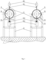
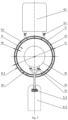
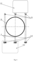
- Method of manufacturing of superspeed transport complex by Yunitski involves installing on foundation 1 of supports 2 (of anchor 2 a and intermediate 2 b types), arrangement and fastening in spans 3 between supports 2 of, at least one prestressed by tensioning in longitudinal direction, trussed overpass 4 (see Figs.1 , 2 , 4 -7 ), embodied as longitudinal trussed 5 track structure of string type with upper 5.1 and lower 5.2 chords of trussed track structure (see Figs.1- 7 and 9 ) for self-powered 6 vehicle (of mounted 6.1 or suspended 6.2 types, correspondingly).
- supports 2 may have different design - in the form of towers, buildings, steel and reinforced concrete columnar and carcass / frame constructs and structures.
- trussed overpasses 4 are installed in spans 3 between supports 2, representing any of the known trussed structures, the common feature of which is, in different embodiments, that they are the principal structural elements of the trussed 5 string-type track structure with increased rigidity and specific carrying capacity.
- preliminary spanning 3 (according to the process of manufacturing of transport complex) is carried out, with truss overpasses 4 made in the form of longitudinal trussed 5 string-type track structure for self-powered 6 vehicle; it becomes possible to provide high-tech possibilities to create large-sized structure of superspeed transport complex in difficult conditions, since at this stage, to manufacture such large-sized structure, trussed overpass 4 with trussed 5 string-type track structure is used as "mounting equipment" for installation of components, and if necessary, of personnel, too, directly to the assembly site of the principal elements of the superspeed transport complex.
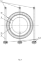
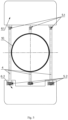
- a further process of manufacturing of the claimed transport complex according to the present invention involves forming and fastening, on at least one trussed overpass 4, transversely to the trussed 5 track structure, of the annular frames 7 (see Figs.8 and 9 ).
- the annular frames 7 are fixed on the trussed 5 track structure by any of the known techniques, for example, by welding.
- the internal P1 and external P2 rows, respectively, of the load-bearing elements P are arranged and fixed, with their subsequent stretching in longitudinal direction to the calculated force.
- internal 8.1 and external 8.2 layers of the sealed evacuated tunnel 9 are formed with annular cross-section profile of its wall 10. Moreover, the internal 8.1 and external 8.2 layers of the sealed evacuated tunnel 9 are formed of hardening composition 11, for example, polymer.
- the internal 8.1 and external 8.2 layers of the sealed evacuated tunnel 9 are formed by, for example, by spraying or extruding the hardening composition 11 onto the internal P1 and external P2 rows of the load-bearing elements P , respectively.
- the internal 8.1 and external 8.2 layers may be made of hardening composition 11, for example polyurethane, and/or polyurea, and/or polyetheretherketone, and/or combinations thereof, which improve physical and operational characteristics of the transport complex.
- hardening composition 11 for example polyurethane, and/or polyurea, and/or polyetheretherketone, and/or combinations thereof, which improve physical and operational characteristics of the transport complex.
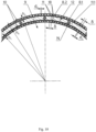
- the space V formed between the internal 8.1 and external 8.2 layers of the wall 10 of the sealed evacuated tunnel 9, is filled with the hardening material 11.1 of the intermediate 12 layer (see Figs.3 , 10 -12 ).
- the hardening material 11.1 of the intermediate 12 layer is made containing load-bearing elements N of the intermediate layer 12, prestressed by tensioning in longitudinal direction and fastened on the annular frames 7 (see Figs. 10 - 12 ), which provides a significant increase in rigidity and specific bearing capacity, with improved physical and operational characteristics of the transport complex.
- load-bearing elements P and N respectively, of the internal 8.1 and external 8.2, as well as intermediate 12 layers of the wall 10 of the sealed evacuated tunnel 9, tensioned in longitudinal direction, can be made in the form of twisted and/or non-twisted ropes, cables, wires, bands and/or other extended elements of any durable materials.
- Hardening material 11.1 of the intermediate layer 12 is used as the hardening material 11.1 of the intermediate layer 12.
- Hardening material 11.1 in the form of reinforced prestressed concrete ensures, at its low cost, an increase in the rigidity of the structure and the specific bearing capacity of the tunneled 14 track structure as a whole.
- special concrete has high armor protection and bulletproof quality.
- polymer concrete and/or foam concrete be used as the hardening material 11.1 of the intermediate layer 12, which will facilitate the construction of the track structure of the transport complex while maintaining its operational characteristics.
- two or more (not shown on Figures) rail cords 13 for superspeed 15 vehicles may be provided.
- polymeric binders or cement mixtures with the addition of corrosion inhibitors, plasticizers and other additives may be used as hardening material 11.1 of the intermediate layer 12, thereby providing a long protection period for load-bearing elements N (see Figs.10 - 13 ) of the intermediate layer 12 against corrosion and mechanical damage.
- Hardening material 11.1 of intermediate layer 12 of sealed evacuated tunnel 9 and hardening materials (not shown on Figures) of the relevant load-bearing constructs of trussed 5 track structure of string type and rail cord 13 of tunneled 14 track structure, depending on design parameters of the corresponding parts of the specified track structures and technical feasibility, can be of the same appearance and type and possess identical composition, or of the different appearance and type and/or possess different composition.
- the hardening materials of the load-bearing constructs of the trussed 5 track structure of string-type and the rail cord 13 of the tunneled 14 track structure can be made of a material of the same kind and type and have the same composition, or - of materials of different type and/or have different composition with hardening compositions 11 of internal 8.1 and external 8.2 layers of wall 10 of sealed evacuated tunnel 9.
- reinforcing shells 18, for example in the form of respective sleeves, or bands, for example of fiberglass fabric, may be fixed on the outer surface of the internal 8.1 layer and the inner surface of the external 8.2 layer of the wall 10 (see Figs. 10 - 12 ).
- These reinforcing shells 18 are designed to occupy the boundary portions of the space V of the intermediate 12 layer and to be impregnated with the hardening material 11.1 of that intermediate 12 layer during the finishing operation of forming the wall 10 of the sealed evacuated tunnel 9.
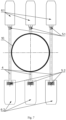
- An alternative embodiment of the method of manufacturing of superspeed transport complex is forming and fastening on trussed overpass 4 of several (two or more) columns of annular frames 7 (not shown on Figures), as well as placement in spans 3 between supports 2 of two, three, four, or more trussed overpasses 4 (see Figs. 1 , 3 and 7 ), shaping both the required number of trussed 5 track structures of string-type for self-powered 6 vehicles and the required number of tunneled 14 track structures for superspeed 15 vehicles, along which the respective vehicles can be driven by any of the known types of drive.
- Such embodiment makes it possible to significantly increase the performance (capacity) of both superspeed transport complex in various directions of traffic, including oncoming, and of its trussed 5 track structures (their upper 5.1 and lower 5.2 chords) due to the combined use, respectively, of mounted 6.1 and suspended 6.2 self-powered vehicles of various modifications and sizes (see Figs.5 - 7 ).
- power unit 17 of superspeed 15 vehicle represents an engine of any of the known types, for example, an engine of rotation, a flywheel accumulator of mechanical energy (such as a gyroscope), a linear electric motor, a propeller, a gas turbine, or in the form of their combinations, with appropriate operation life support and drive systems for driving (traction) wheels.
- the power unit 17 would be an electric motor in the form of a motor wheel (not shown on Figures).
- the manufacturing of the superspeed transport complex can be carried out using a special small-sized construction combine / road header (not shown on Figures), which can be installed, for the period of construction, on one and/or several trussed 5 track structures instead of the corresponding self-powered 6 vehicles stipulated by the design option, which significantly improves the processability of manufacturing process of this complex.
- the combine simulates the natural load on the trussed overpasses 4, which allows to take into consideration the deformation thereof and to ensure the required straightforwardness of the tunneled 14 track structure of the superspeed transport complex created thereby.
- the combine moving along the route along trussed overpasses 4, provides for the tunneled 14 track structures for superspeed 15 vehicles mounted according to the design option.
- the track structures (longitudinal trussed 5 track structure of string type for self-powered 6 vehicle, and tunneled 14 track structure for superspeed 15 vehicle), according to the design option, are equipped with stations 19 with respective boarding platforms 20 (see Fig.13 ). Buildings, or various structures can be used ss stations, including train stations, anchor supports and/or other building structures.
- the superspeed transport complex by Yunitski implemented according to the above described method as per present invention, comprises at least one trussed 5 track structure of string type (see Figs. 1 and 2 ), installed on supports 2 (anchor 2 a and intermediate 2 b types, mounted from soil and distributed along foundation 1), and fastened in spans 3 between these supports 2.
- Trussed 5 track structure of string type is made in the form of trussed overpass 4, prestressed by tensioning in longitudinal direction.
- the trussed overpass 4 together with the trussed 5 track structure of string type, is provided with a self-powered 6 vehicle (mounted 6.1 or suspended 6.2), as shown on Figs. 1 , 3 , 5 - 7 and 13 .
- the structures of trussed overpasses 4 in spans 3 may be different depending on the terrain, design parameters and engineering viability / technical feasibility.
- Fig. 1 a layout view of superspeed transport complex with two trussed overpasses 4 and, accordingly, two trussed 5 track structures of string type, is shown.
- Figs. 3 and 9 illustrate layout views of superspeed transport complex with three trussed overpasses 4.
- the structure of the proposed transport complex provides for the formation and fixation on at least one trussed overpass 4, transversely to the trussed 5 track structure, of annular frames 7, located at least in one column (see Fig. 9 ).
- annular frames 7, located at least in one column On the inner A and outer B surfaces of the annular frames 7, arranged and fastened are, respectively, the internal P1 and external P2 rows of load-bearing elements P , which are subsequently stressed by tensioning in longitudinal direction (see Fig. 8 ).
- one trussed 5 string track structure of overpass type is connected to one tunneled 14 track structure including a sealed evacuated tunnel 9 with an annular cross-sectional profile of its wall 10 consisting of internal 8.1, external 8.2 and intermediate 12 layers.
- annular frames 7 are positioned from each other at the distance L , m, defined by the dependence: 0.1 ⁇ L / D ⁇ 5 , where D , m - outer diameter of the sealed evacuated tunnel.
- the ratio (1) is less than 0.1, then there is an unjustified overspending of structural materials and, as a result, - an increase in the cost of the track structure.
- ratio (1) is more than 5, it becomes problematic to ensure the required rigidity and straightness of the arrangement of the tunneled 14 track structure.
- annular frames 7 of wall 10 of sealed evacuated tunnel 9 are connected with each of its layers (internal 8.1, external 8.2 and intermediate 12), and, together with the respective rows P1 and P2 of load-bearing elements P and load-bearing elements N of intermediate 12 layer of wall 10 of sealed evacuated tunnel 9, are forming the reinforced carcass of tunneled 14 track structure.
- Fixing of internal P1 and external P2 rows of load-bearing elements P on annular frames 7, as well as of load-bearing elements N of the intermediate 12 layer, can be performed in any known way, for example, by gluing, or kinematic locking (not shown on Figures), for example, by wedging in the corresponding holes (and/or slots).
- the hardening composition 11 for example, polyurethane, and/or polyurea, and/or polyetheretherketone, and/or combinations thereof are used, which ensures the durability of the structure and high processability of the manufacturing process of the claimed transport complex.
- the formed space V of the intermediate 12 layer is thereby filled with the hardening material 11.1.
- concrete is preferably used to fill the space V of the intermediate 12 layer. This will ensure the required strength, safety and rigidity of the wall 10 of the sealed evacuated tunnel 9, with high processability of the manufacturing process of the tunneled 14 track structure and optimized costs.
- the hardening material 11.1 of the intermediate 12 layer it is advantageous to use, for example, polymer concrete and/or foam concrete, which will facilitate the construction of the track structure of the transport complex while maintaining its field performance.
- the internal 8.1 and external 8.2 layers of wall 10 of sealed evacuated tunnel 9 are made with thicknesses, respectively, h 1 , m, and h 2 , m, defined by the ratios: 0.01 ⁇ h 1 / h 0 ⁇ 0.1 , 0.01 ⁇ h 2 / h 0 ⁇ 0.1
- ratios (2) and (3) are less than 0.01, then it is difficult to guarantee the rigidity stipulated by the design option, as well as durability and shape of the internal 8.1 and external 8.2 layers and wall 10 of the sealed evacuated tunnel 9 in general, at the subsequent filling with the hardening material 11.1 of the space V of the intermediate 12 layer formed therebetween.
- ratios (2) and (3) are more than 0.1, then there is an unjustified overrun of structural materials (including hardening composition 11) and, as a result, - an increase in the cost of the track structure.
- the load-bearing elements P of the internal 8.1 and external 8.2 layers of the wall 10 of the sealed evacuated tunnel 9 are made (see Figs. 10 - 12 ) with a diameter, d 0 , m, defined by the ratios: 0.25 ⁇ d 0 / h 1 ⁇ 0.95 , 0.25 ⁇ d 0 / h 2 ⁇ 0.95
- ratios (4) and (5) are less than 0.25, it is difficult to ensure the required rigidity, strength and shape of the internal 8.1 and external 8.2 layers and the wall 10 of the sealed evacuated tunnel 9 as a whole, when the space V of the intermediate 12 layer formed therebetween is subsequently filled with hardening material 11.1.
- ratios (4) and (5) are more than 0.95, then there is an unjustified overrun of structural materials (including load-bearing elements P ) and, as a result, an increase in the cost of the track structure.
- the adjacent load-bearing elements P of the internal 8.1 and external 8.2 layers of wall 10 of the sealed evacuated tunnel 9 are positioned (see Figs. 10 - 12 ) between each other with gap ⁇ , m, defined by the ratio: 0 ⁇ ⁇ / d 0 ⁇ 5
- the ratio (6) cannot be less than 0, since the gap cannot be negative.
- the ratio (6) is more than 5, the significant thickness of the hardening composition 11 in the gap ⁇ , m, between adjacent load-bearing elements 6 will not provide the required strength, bearing capacity and geometry of internal 8.1 and external 8.2 layers of wall 10 of sealed evacuated tunnel 9 at subsequent filling with hardening material 11.1 of space V of the intermediate 12 layer formed between the said boundary layers (8.1 and 8.2).
- the intermediate layer 12 of wall 10 of sealed evacuated tunnel 9 is made with thickness h 0 , m, defined by the ratio: 0.025 ⁇ h 0 / D ⁇ 0.25
- the ratio (7) is less than 0.1, then there is an unjustified overspending of structural materials and, as a result, an increase in the cost of the track structure.
- the ratio (7) is more than 2.5, it becomes problematic to ensure the required rigidity and straightness of the arrangement of the tunneled 14 track structure.
- load-bearing elements for load-bearing structures of such elements of the transport complex, like: trussed 5 track structure of string type, and/or rail cord 13 of tunneled 14 track structure, and/or load-bearing elements P of internal 8.1 and external 8.2 layers, and/or load-bearing elements of intermediate 12 layer, - the following reinforcing elements can be used: high-strength steel wire, or twisted or untwisted steel ropes, as well as cords, strands, bands, tubes or other extended elements made of known high-strength materials in any combination thereof.
- reinforcing shells 18 may be fastened to the outer surface of the internal 8.1 layer and the inner surface of the external 8.2 layer (see Figs. 10 - 12 ). Those reinforcing shells 18 are configured so that they are immersed in both the internal 8.1 and external 8.2 layers of the wall 10 by the hardening composition 11 and in the intermediate 12 layer thereof by the respective hardening material 11.1 along the entire length of the sealed evacuated tunnel 9.
- two or more rail cords 13 may be provided for superspeed 15 vehicle (not shown on Figures).
- the superspeed 15 vehicle comprises body 16 with power unit 17, ensuring sealing of the cabin during movement (see Fig. 2 ).
- trussed 5 and tunneled 14 track structures are equipped with stations 19 with boarding platforms 20 (see Fig. 13 ).
- stations buildings, or various structures can be used, including train stations, anchor supports and/or other building structures.
- At least one trussed 5 string track structure of overpass type provides for, at the stage of operation of the superspeed transport complex, the functioning of the self-powered 6 vehicle (mounted 6.1, or suspended 6.2), and at the stage of construction - the assembling of sealed evacuated tunnel 9 of the tunneled 14 track structure of the superspeed 15 vehicle.
- the trussed overpasses after installation of the tunneled 14 track structure, can be dismantled, which will save up materials and, as a result, reduce the cost of the transport complex as a whole.
- Construction of the superspeed transport complex by Yunitski according to the present invention is carried out by the following technological operations.
- Supports 2 are installed on bases prepared on foundation 1 from soil.
- Load-bearing member of the trussed 5 track structure is suspended on the supports 2 and stretched therebetween with subsequent fastening of the ends of the load-bearing elements in the anchor supports 2 a .
- trussed overpass 4 in form of longitudinal trussed 5 string-type track structure for self-powered 6 vehicle is mounted on load-bearing member in spans 3 between supports 2.
- the technological equipment After assembly, along the length of the entire track of at least one trussed 4 overpass prestressed by tensioning in longitudinal direction, the technological equipment is placed on its trussed 5 string-type track structure for the manufacture of the tunneled 14 track structure (for example, a special construction combine).
- the subsequent stage of the manufacturing process involves the formation and fastening of annular frames 7, for example - by welding on trussed 5 track structure.
- annular frames 7, for example - by welding on trussed 5 track structure Following that, on inner A and outer B surfaces of annular frames 7, internal P1 and external P2 rows, respectively, of load-bearing elements P are installed and fixed, tensioned between anchor 2 a supports, and via special through holes in annular frames 7, the load-bearing elements N of the intermediate layer 12 of the tunneled 14 track structure are inserted and fixed in pretensioned state between the same anchor supports 2 a . As a result, a reinforced carcass of the tunneled 14 structure is formed.
- the internal 8.1 and the external 8.2 layers of the wall 10 of the sealed evacuated tunnel 9 are first formed, and then its intermediate 12 layer is formed by applying hardening compositions 11 and hardening material 11.1 on the corresponding areas of the obtained carcass, into the space V formed between the internal and external layers of the wall of the sealed evacuated tunnel 9.
- Rail cord 13 of tunneled 14 track structure is fixed in shaped hermetically evacuated tunnel 9, whereon superspeed 15 vehicle is installed.
- the transport complex is equipped with stations 19 and boarding platforms 20, and corresponding self-powered 6 vehicles are installed on trussed 5 track structures.
- the proposed invention is industrially applicable since the superspeed transport complex can be realized under real conditions using standard equipment, modern materials and technologies.
- the proposed method of manufacturing and arrangement of superspeed transport complex by Yunitski make it possible to ensure: increase of technological effectiveness of the manufacturing process and design of the superspeed transport complex as a whole; increase of specific bearing capacity of track structures; improvement of operational and technical characteristics of the transport complex; improving the rigidity of the structure, as well as the flatness of the rail track.
Landscapes
- Engineering & Computer Science (AREA)
- Mechanical Engineering (AREA)
- Architecture (AREA)
- Civil Engineering (AREA)
- Structural Engineering (AREA)
- General Engineering & Computer Science (AREA)
- Lining And Supports For Tunnels (AREA)
Claims (11)
- Verfahren zur Fertigung eines Hochgeschwindigkeits-Transportkomplexes, wobei das Verfahren enthält:ein Installieren von Trägern (2) auf einem Fundament (1);ein Erstellen und Befestigen, in Spannweiten (3) zwischen den Trägern (2), mindestens einer Überführung (4), die durch ein Spannen in Längsrichtung vorgespannt ist, in der Form einer Längsgleisstruktur vom Strangtyp für ein selbstangetriebenes Fahrzeug (6);ein Ausbilden und Befestigen von ringförmigen Rahmen (7) an der Überführung (4) quer zu der Gleisstruktur;ein Anordnen und Befestigen von inneren und äußeren Reihen von lasttragenden Elementen (P), die in Längsrichtung gespannt sind, jeweilig an inneren und äußeren Flächen der ringförmigen Rahmen (7);dadurch gekennzeichnet, dassdie mindestens eine Überführung (4), die die Längsgleisstruktur ausbildet, fachwerkartig ist; undgekennzeichnet durchein Ausbilden von inneren und äußeren Schichten (8,1, 8,2) von mindestens einem abgedichteten evakuierten Tunnel (9), dessen Wand (10) ein ringförmiges Querschnittsprofil hat, die aus einer aushärtenden Zusammensetzung gefertigt ist, indem sie jeweilig auf die inneren und äußeren Reihen von lasttragenden Elementen (P) aufgebracht werden und der Raum zwischen den ausgebildeten inneren und äußeren Schichten (8,1, 8,2) des abgedichteten evakuierten Tunnels (9) mit dem aushärtenden Material der Zwischenschicht gefüllt wird,während auf der inneren Schicht (8,1) der Wand (10) des abgedichteten evakuierten Tunnels (9) ein durch ein Spannen in Längsrichtung vorgespanntes mindestens ein Schienenkabel (13) einer Gleisstruktur mit Tunnel für ein Hochgeschwindigkeitsfahrzeug, das eine Karosserie mit einer Antriebseinheit enthält, die ein Abdichten der Kabine während einer Bewegung bereitstellt, positioniert wird.
- Hochgeschwindigkeits-Transportkomplex, der durch das Verfahren nach Anspruch 1 hergestellt ist, der wobei der Komplex, montiert in Spannweiten (3) zwischen Trägern (2), die auf dem Fundament (1) angeordnet sind, mindestens eine fachwerkartige Stranggleisstruktur eines Überführungstyps enthält; mit mindestens einem selbstangetriebenen Fahrzeug (6), das darauf montiert ist; verbunden mit mindestens einer Gleisstruktur mit Tunnel, die einen abgedichteten evakuierten Tunnel (9) enthält, dessen Wand (10) ein ringförmiges Querschnittsprofil hat; bestehend aus inneren Schichten, äußeren Schichten und Zwischenschichten (8,1, 8,2, 12) und mindestens einem Schienenkabel (13), das sich in dem abgedichteten evakuierten Tunnel (9) befindet, der für ein Hochgeschwindigkeitsfahrzeug mit einer Karosserie, die ein Abdichten der Kabine während einer Bewegung bereitstellt, und einer Antriebseinheit bestimmt ist, wobei die Wand (10) des abgedichteten evakuierten Tunnels (9) mit ringförmigen Rahmen (7) ausgestattet ist, die mit jeder der Schichten der Wand (10) verbunden sind; und dessen innere und äußere Schichten (8,1, 8,2) aus einer aushärtenden Zusammensetzung gefertigt sind und mit durch ein Spannen in Längsrichtung vorgespannten entsprechenden lasttragenden Elementen (P) verstärkt sind; die jeweilig an den inneren und äußeren Flächen der ringförmigen Rahmen (7) befestigt sind; und wobei die Zwischenschicht (12) der Wand aus einem aushärtenden Material gefertigt ist, das den Raum zwischen den inneren und äußeren Schichten (8,1, 8,2) der Wand (10) füllt.
- Hochgeschwindigkeits-Transportkomplex nach Anspruch 2, dadurch gekennzeichnet, dass das aushärtende Material der Zwischenschicht (12) der Wand des abgedichteten evakuierten Tunnels (9) lasttragende Elemente (P) der Zwischenschicht (12) enthält, die durch ein Spannen in Längsrichtung bis zu der nominalen Konstruktionskraft vorgespannt sind und an den ringförmigen Rahmen (7) befestigt sind.
- Hochgeschwindigkeits-Transportkomplex nach Anspruch 3, dadurch gekennzeichnet, dass Beton als das aushärtende Material der Zwischenschicht (12) der Wand (10) des abgedichteten evakuierten Tunnels (9) verwendet wird.
- Hochgeschwindigkeits-Transportkomplex nach Anspruch 2, dadurch gekennzeichnet, dass die inneren und äußeren Schichten (8,1, 8,2) der Wand (10) des abgedichteten evakuierten Tunnels (9) aus einer verstärkten polymeren aushärtenden Zusammensetzung in der Form von Polyurethan und/oder Polyharnstoff und/oder Polyetheretherketon und/oder Kombinationen aus diesen gefertigt sind.
- Hochgeschwindigkeits-Transportkomplex nach Anspruch 2, dadurch gekennzeichnet, dass die ringförmigen Rahmen (7) voneinander in dem Abstand L [m] positioniert sind, der durch die folgende Abhängigkeit definiert ist:

- Hochgeschwindigkeits-Transportkomplex nach Anspruch 2, dadurch gekennzeichnet, dass die Zwischenschicht (12) der Wand (10) des abgedichteten evakuierten Tunnels (9) mit einer Dicke h0 [m] gefertigt ist, die durch das folgende Verhältnis definiert ist:

- Hochgeschwindigkeits-Transportkomplex nach Anspruch 2, dadurch gekennzeichnet, dass die inneren und äußeren Schichten (8,1, 8,2) der Wand (10) des abgedichteten evakuierten Tunnels (9) mit jeweiligen Dicken h1 [m] und h2 [m] gefertigt sind, die durch die folgenden Verhältnisse definiert sind:


- Hochgeschwindigkeits-Transportkomplex nach Anspruch 2, dadurch gekennzeichnet, dass die lasttragenden Elemente (P) der inneren und äußeren Schichten (8,1, 8,2) der Wand (10) des abgedichteten evakuierten Tunnels (9) mit einem Durchmesser d0 [m] gefertigt sind, der durch die folgenden Verhältnisse definiert ist:


- Hochgeschwindigkeits-Transportkomplex nach Anspruch 9, dadurch gekennzeichnet, dass die benachbarten lasttragenden Elemente (P) der inneren und äußeren Schichten (8,1, 8,2) der Wand (10) des abgedichteten evakuierten Tunnels (9) mit einem Spalt δ [m] zwischen einander positioniert sind, der durch das folgende Verhältnis definiert ist:

- Hochgeschwindigkeits-Transportkomplex nach Anspruch 2, dadurch gekennzeichnet, dass die benachbarten Schichten der Wand (10) des abgedichteten evakuierten Tunnels (9) in der Querrichtung entlang ihrer gesamten Länge miteinander verbunden sind.
Applications Claiming Priority (2)
| Application Number | Priority Date | Filing Date | Title |
|---|---|---|---|
| EA201900540A EA038723B1 (ru) | 2019-09-11 | 2019-09-11 | Способ изготовления и устройство сверхскоростного транспортного комплекса юницкого |
| PCT/BY2020/000011 WO2021046627A1 (ru) | 2019-09-11 | 2020-11-11 | Способ изготовления и устройство сверхскоростного транспортного комплекса |
Publications (4)
| Publication Number | Publication Date |
|---|---|
| EP4029754A1 EP4029754A1 (de) | 2022-07-20 |
| EP4029754A4 EP4029754A4 (de) | 2023-05-10 |
| EP4029754C0 EP4029754C0 (de) | 2025-03-12 |
| EP4029754B1 true EP4029754B1 (de) | 2025-03-12 |
Family
ID=74867087
Family Applications (1)
| Application Number | Title | Priority Date | Filing Date |
|---|---|---|---|
| EP20862498.1A Active EP4029754B1 (de) | 2019-09-11 | 2020-11-11 | Verfahren zur herstellung eines ultraschnellen transportkomplexes |
Country Status (4)
| Country | Link |
|---|---|
| EP (1) | EP4029754B1 (de) |
| CN (1) | CN114765977B (de) |
| EA (1) | EA038723B1 (de) |
| WO (1) | WO2021046627A1 (de) |
Families Citing this family (3)
| Publication number | Priority date | Publication date | Assignee | Title |
|---|---|---|---|---|
| CA3249089A1 (en) * | 2022-02-28 | 2023-08-31 | Arcelormittal | METHOD FOR ERECTING A TRANSPORTATION STRUCTURE |
| IT202300028350A1 (it) * | 2023-12-29 | 2025-06-29 | Aeronautical Service S R L | Tubo per trasporto ad alta velocità di merci e passeggeri in ambiente a bassa pressione e procedimento per la sua realizzazione |
| US12479667B1 (en) | 2024-07-26 | 2025-11-25 | Anatoli Eduardovich Unitsky | Cargo transport complex |
Family Cites Families (22)
| Publication number | Priority date | Publication date | Assignee | Title |
|---|---|---|---|---|
| RU2080268C1 (ru) * | 1994-04-08 | 1997-05-27 | Капитонов Александр Александрович | Линейная транспортная система |
| RU2109647C1 (ru) | 1995-03-28 | 1998-04-27 | Петр Федорович Костромин | Сверхскоростная транспортная система с электропоездом "уральская ракета" |
| DE10111957A1 (de) * | 2001-03-13 | 2002-09-19 | Baumann Theodor | Schnellbahnfahrweg, insbesondere einspurig, innerhalb einer durch Tübbinge gebildeten Streckenföhre, aufgeweitet zu einer durch Tübbinge gebildeten Stationsröhre mit zwei Fahrbahnen und Verfahren zu dessen Herstellung |
| RU2252881C2 (ru) | 2001-04-11 | 2005-05-27 | Янсуфин Нигматулла Рахматуллович | Сверхзвуковая наземная транспортная система янсуфина |
| DE10225967C1 (de) * | 2002-06-11 | 2003-10-30 | Guenther Purbach | Multifunktionale Trajekttrasse und integrierte Transportsysteme |
| UA76484C2 (en) * | 2004-02-20 | 2006-08-15 | Oleksandr Oleksandro Kapitonov | Kapitonovæs transport system (variants) |
| CN2835013Y (zh) * | 2004-04-20 | 2006-11-08 | 艾乔乔 | 浅埋型地下轨道列车隧道系统 |
| RU2271291C2 (ru) * | 2004-04-26 | 2006-03-10 | Евгений Николаевич Хрусталёв | Способ сооружения городской магистрали и устройство городской магистрали |
| UA70421C2 (en) * | 2004-07-12 | 2004-10-15 | Serhii Mykolaiovycj Kuschenko | Multi-layer pipe and method to make a multi-layer multi-layer pipe and method to make a multi-layer pipe pipe |
| CN200954819Y (zh) * | 2006-04-07 | 2007-10-03 | 艾乔乔 | 主副单轨道地铁列车及浅埋型地铁隧道系统 |
| RU2333103C2 (ru) * | 2006-08-24 | 2008-09-10 | Открытое акционерное общество Центральный научно-исследовательский институт специального машиностроения | Способ изготовления трубы из слоистого композиционного материала и труба из слоистого композиционного материала |
| CN101746378A (zh) * | 2008-12-16 | 2010-06-23 | 彭智祥 | 一种轻质气体管道 |
| RU2503560C2 (ru) * | 2009-12-25 | 2014-01-10 | Владимир Афанасьевич Третьяков | Способ антитеррористической сверхскоростной межмегаполисной перевозки пассажиров и грузов |
| WO2016126503A1 (en) * | 2015-02-08 | 2016-08-11 | Hyperloop Technologies, Inc | Transportation system |
| CN105015558B (zh) * | 2015-08-06 | 2021-06-01 | 高阳 | 一种利用电磁力和惯性力驱动、磁力平衡独轨单车轮的真空管高速列车 |
| WO2018098405A2 (en) * | 2016-11-28 | 2018-05-31 | Hodgetts Craig | Construction of large diameter concrete pneumatic tube for transportation system |
| KR101853915B1 (ko) * | 2017-11-21 | 2018-05-02 | 한국건설기술연구원 | 초고속 튜브철도용 슬래브-캐노피 합성모듈형 운송관 구조물 및 그 시공방법 |
| EP3755530B1 (de) * | 2018-02-24 | 2022-01-26 | Tata Steel Nederland Technology B.V. | Rohrsegment und rohr für evakuiertes rohrtransportsystem |
| CN108755294A (zh) * | 2018-08-06 | 2018-11-06 | 北京交通大学 | 一种腹板开孔的单箱单室高架磁浮交通 |
| CN210912405U (zh) * | 2019-07-15 | 2020-07-03 | 北京九州动脉隧道技术有限公司 | 一种用于真空管道运输的管道装置 |
| CN110775074A (zh) * | 2019-12-05 | 2020-02-11 | 深圳大学 | 月基恒温层地下真空飞行轨道交通系统 |
| CN111775971A (zh) * | 2020-07-13 | 2020-10-16 | 中铁第五勘察设计院集团有限公司 | 一种低真空管道运输系统 |
-
2019
- 2019-09-11 EA EA201900540A patent/EA038723B1/ru unknown
-
2020
- 2020-11-11 EP EP20862498.1A patent/EP4029754B1/de active Active
- 2020-11-11 CN CN202080070495.9A patent/CN114765977B/zh active Active
- 2020-11-11 WO PCT/BY2020/000011 patent/WO2021046627A1/ru not_active Ceased
Also Published As
| Publication number | Publication date |
|---|---|
| EA201900540A1 (ru) | 2021-03-31 |
| EP4029754A4 (de) | 2023-05-10 |
| EA038723B1 (ru) | 2021-10-11 |
| EP4029754C0 (de) | 2025-03-12 |
| CN114765977A (zh) | 2022-07-19 |
| CN114765977B (zh) | 2024-12-27 |
| WO2021046627A1 (ru) | 2021-03-18 |
| EP4029754A1 (de) | 2022-07-20 |
Similar Documents
| Publication | Publication Date | Title |
|---|---|---|
| EP4029754A1 (de) | Verfahren zur herstellung eines ultraschnellen transportkomplexes | |
| KR102490998B1 (ko) | 수송 시스템 | |
| US10046776B2 (en) | Low-pressure environment structures | |
| CN102015406B (zh) | 用于具有气动推进系统的车辆的改进的高架轨道 | |
| RU2325293C2 (ru) | Струнная транспортная система юницкого и способ построения струнной транспортной системы | |
| JP2022548929A (ja) | 真空チューブ輸送システム用のチューブ部分 | |
| EP3974278B1 (de) | Hochgeschwindigkeitstransportsystem | |
| RU2475386C1 (ru) | Транспортная система юницкого и способ построения струнной транспортной системы | |
| EP3395637B1 (de) | Kommunikationssystem | |
| EP3992049B1 (de) | Transportsystem | |
| CN111417558B (zh) | 串式轨道结构 | |
| RU2252881C2 (ru) | Сверхзвуковая наземная транспортная система янсуфина | |
| CN115397712B (zh) | 运输系统 | |
| RU2252880C2 (ru) | Скоростная наземная транспортная система | |
| KR20200112849A (ko) | 비워진 튜브 운송 시스템용 튜브 및 튜브 세그먼트 | |
| CN212248357U (zh) | 一种地铁车站轨行区预制拼装混凝土隔墙结构 | |
| CN114728662A (zh) | 弦式运输系统 | |
| EA034463B1 (ru) | Система коммуникаций юницкого и её применение для транспортировки жидкостей и/или газов и/или в сетях электроснабжения и/или связи | |
| EA034490B1 (ru) | Ферменная путевая структура скоростной транспортной системы, рельсовая нить ферменной путевой структуры скоростной транспортной системы и способ изготовления ферменной путевой структуры и рельсовой нити | |
| CN112681372B (zh) | 一种用于既有高架运营地铁车站改扩建施工的桁车 | |
| EA033575B1 (ru) | Система коммуникаций юницкого и её применение для транспортировки жидкостей и/или газов и/или в сетях электроснабжения и/или связи | |
| UA76484C2 (en) | Kapitonovæs transport system (variants) | |
| CN113373741A (zh) | 管隧分离式的隧道-真空管道结构 |
Legal Events
| Date | Code | Title | Description |
|---|---|---|---|
| STAA | Information on the status of an ep patent application or granted ep patent |
Free format text: STATUS: THE INTERNATIONAL PUBLICATION HAS BEEN MADE |
|
| PUAI | Public reference made under article 153(3) epc to a published international application that has entered the european phase |
Free format text: ORIGINAL CODE: 0009012 |
|
| STAA | Information on the status of an ep patent application or granted ep patent |
Free format text: STATUS: REQUEST FOR EXAMINATION WAS MADE |
|
| 17P | Request for examination filed |
Effective date: 20220411 |
|
| AK | Designated contracting states |
Kind code of ref document: A1 Designated state(s): AL AT BE BG CH CY CZ DE DK EE ES FI FR GB GR HR HU IE IS IT LI LT LU LV MC MK MT NL NO PL PT RO RS SE SI SK SM TR |
|
| XX | Miscellaneous (additional remarks) |
Free format text: THE FILING DATE OF THE INTERNATIONAL APPLICATION IS WITHIN TWO MONTHS FROM THE DATE OF EXPIRATION OF THE PRIORITY PERIOD (R. 26BIS.3 PCT). |
|
| XX | Miscellaneous (additional remarks) |
Free format text: THE FILING DATE OF THE INTERNATIONAL APPLICATION IS WITHIN TWO MONTHS FROM THE DATE OF EXPIRATION OF THE PRIORITY PERIOD (R. 26BIS.3 PCT). |
|
| A4 | Supplementary search report drawn up and despatched |
Effective date: 20230406 |
|
| RIC1 | Information provided on ipc code assigned before grant |
Ipc: E01B 25/30 20060101ALI20230331BHEP Ipc: E01B 2/00 20060101ALI20230331BHEP Ipc: E01B 25/00 20060101ALI20230331BHEP Ipc: B61B 13/00 20060101ALI20230331BHEP Ipc: B61B 5/02 20060101ALI20230331BHEP Ipc: B61B 3/02 20060101AFI20230331BHEP |
|
| RAP3 | Party data changed (applicant data changed or rights of an application transferred) |
Owner name: UNITSKY, ANATOLI EDUARDOVICH |
|
| RIN1 | Information on inventor provided before grant (corrected) |
Inventor name: UNITSKY, ANATOLI EDUARDOVICH |
|
| DAV | Request for validation of the european patent (deleted) | ||
| DAX | Request for extension of the european patent (deleted) | ||
| GRAJ | Information related to disapproval of communication of intention to grant by the applicant or resumption of examination proceedings by the epo deleted |
Free format text: ORIGINAL CODE: EPIDOSDIGR1 |
|
| GRAP | Despatch of communication of intention to grant a patent |
Free format text: ORIGINAL CODE: EPIDOSNIGR1 |
|
| RIC1 | Information provided on ipc code assigned before grant |
Ipc: B29D 23/00 20060101ALI20240909BHEP Ipc: E01B 25/30 20060101ALI20240909BHEP Ipc: E01B 2/00 20060101ALI20240909BHEP Ipc: E01B 25/00 20060101ALI20240909BHEP Ipc: B61B 13/00 20060101ALI20240909BHEP Ipc: B61B 5/02 20060101ALI20240909BHEP Ipc: B61B 3/02 20060101AFI20240909BHEP |
|
| GRAP | Despatch of communication of intention to grant a patent |
Free format text: ORIGINAL CODE: EPIDOSNIGR1 |
|
| STAA | Information on the status of an ep patent application or granted ep patent |
Free format text: STATUS: GRANT OF PATENT IS INTENDED |
|
| INTG | Intention to grant announced |
Effective date: 20241024 |
|
| GRAS | Grant fee paid |
Free format text: ORIGINAL CODE: EPIDOSNIGR3 |
|
| GRAA | (expected) grant |
Free format text: ORIGINAL CODE: 0009210 |
|
| STAA | Information on the status of an ep patent application or granted ep patent |
Free format text: STATUS: THE PATENT HAS BEEN GRANTED |
|
| AK | Designated contracting states |
Kind code of ref document: B1 Designated state(s): AL AT BE BG CH CY CZ DE DK EE ES FI FR GB GR HR HU IE IS IT LI LT LU LV MC MK MT NL NO PL PT RO RS SE SI SK SM TR |
|
| REG | Reference to a national code |
Ref country code: GB Ref legal event code: FG4D |
|
| XX | Miscellaneous (additional remarks) |
Free format text: THE FILING DATE OF THE INTERNATIONAL APPLICATION IS WITHIN TWO MONTHS FROM THE DATE OF EXPIRATION OF THE PRIORITY PERIOD (R. 26BIS.3 PCT). |
|
| REG | Reference to a national code |
Ref country code: CH Ref legal event code: EP |
|
| REG | Reference to a national code |
Ref country code: DE Ref legal event code: R096 Ref document number: 602020047722 Country of ref document: DE |
|
| REG | Reference to a national code |
Ref country code: IE Ref legal event code: FG4D |
|
| U01 | Request for unitary effect filed |
Effective date: 20250409 |
|
| U07 | Unitary effect registered |
Designated state(s): AT BE BG DE DK EE FI FR IT LT LU LV MT NL PT RO SE SI Effective date: 20250415 |
|
| PG25 | Lapsed in a contracting state [announced via postgrant information from national office to epo] |
Ref country code: RS Free format text: LAPSE BECAUSE OF FAILURE TO SUBMIT A TRANSLATION OF THE DESCRIPTION OR TO PAY THE FEE WITHIN THE PRESCRIBED TIME-LIMIT Effective date: 20250612 |
|
| PG25 | Lapsed in a contracting state [announced via postgrant information from national office to epo] |
Ref country code: ES Free format text: LAPSE BECAUSE OF FAILURE TO SUBMIT A TRANSLATION OF THE DESCRIPTION OR TO PAY THE FEE WITHIN THE PRESCRIBED TIME-LIMIT Effective date: 20250312 |
|
| PG25 | Lapsed in a contracting state [announced via postgrant information from national office to epo] |
Ref country code: NO Free format text: LAPSE BECAUSE OF FAILURE TO SUBMIT A TRANSLATION OF THE DESCRIPTION OR TO PAY THE FEE WITHIN THE PRESCRIBED TIME-LIMIT Effective date: 20250612 |
|
| PG25 | Lapsed in a contracting state [announced via postgrant information from national office to epo] |
Ref country code: HR Free format text: LAPSE BECAUSE OF FAILURE TO SUBMIT A TRANSLATION OF THE DESCRIPTION OR TO PAY THE FEE WITHIN THE PRESCRIBED TIME-LIMIT Effective date: 20250312 |
|
| PG25 | Lapsed in a contracting state [announced via postgrant information from national office to epo] |
Ref country code: GR Free format text: LAPSE BECAUSE OF FAILURE TO SUBMIT A TRANSLATION OF THE DESCRIPTION OR TO PAY THE FEE WITHIN THE PRESCRIBED TIME-LIMIT Effective date: 20250613 |
|
| PG25 | Lapsed in a contracting state [announced via postgrant information from national office to epo] |
Ref country code: SM Free format text: LAPSE BECAUSE OF FAILURE TO SUBMIT A TRANSLATION OF THE DESCRIPTION OR TO PAY THE FEE WITHIN THE PRESCRIBED TIME-LIMIT Effective date: 20250312 |
|
| PG25 | Lapsed in a contracting state [announced via postgrant information from national office to epo] |
Ref country code: PL Free format text: LAPSE BECAUSE OF FAILURE TO SUBMIT A TRANSLATION OF THE DESCRIPTION OR TO PAY THE FEE WITHIN THE PRESCRIBED TIME-LIMIT Effective date: 20250312 |
|
| PG25 | Lapsed in a contracting state [announced via postgrant information from national office to epo] |
Ref country code: CZ Free format text: LAPSE BECAUSE OF FAILURE TO SUBMIT A TRANSLATION OF THE DESCRIPTION OR TO PAY THE FEE WITHIN THE PRESCRIBED TIME-LIMIT Effective date: 20250312 |
|
| PG25 | Lapsed in a contracting state [announced via postgrant information from national office to epo] |
Ref country code: SK Free format text: LAPSE BECAUSE OF FAILURE TO SUBMIT A TRANSLATION OF THE DESCRIPTION OR TO PAY THE FEE WITHIN THE PRESCRIBED TIME-LIMIT Effective date: 20250312 |
|
| PG25 | Lapsed in a contracting state [announced via postgrant information from national office to epo] |
Ref country code: IS Free format text: LAPSE BECAUSE OF FAILURE TO SUBMIT A TRANSLATION OF THE DESCRIPTION OR TO PAY THE FEE WITHIN THE PRESCRIBED TIME-LIMIT Effective date: 20250712 |
|
| PLBE | No opposition filed within time limit |
Free format text: ORIGINAL CODE: 0009261 |
|
| STAA | Information on the status of an ep patent application or granted ep patent |
Free format text: STATUS: NO OPPOSITION FILED WITHIN TIME LIMIT |
|
| REG | Reference to a national code |
Ref country code: CH Ref legal event code: L10 Free format text: ST27 STATUS EVENT CODE: U-0-0-L10-L00 (AS PROVIDED BY THE NATIONAL OFFICE) Effective date: 20260121 |
|
| 26N | No opposition filed |
Effective date: 20251215 |
|
| REG | Reference to a national code |
Ref country code: CH Ref legal event code: H13 Free format text: ST27 STATUS EVENT CODE: U-0-0-H10-H13 (AS PROVIDED BY THE NATIONAL OFFICE) Effective date: 20260623 |
|
| PG25 | Lapsed in a contracting state [announced via postgrant information from national office to epo] |
Ref country code: MC Free format text: LAPSE BECAUSE OF FAILURE TO SUBMIT A TRANSLATION OF THE DESCRIPTION OR TO PAY THE FEE WITHIN THE PRESCRIBED TIME-LIMIT Effective date: 20250312 |
|
| U90 | Renewal fees not paid: noting of loss of rights |
Free format text: RENEWAL FEE NOT PAID FOR YEAR 06 Effective date: 20260616 |
|
| PG25 | Lapsed in a contracting state [announced via postgrant information from national office to epo] |
Ref country code: CH Free format text: LAPSE BECAUSE OF NON-PAYMENT OF DUE FEES Effective date: 20251130 |