EP4029664A2 - Pince aspirante - Google Patents
Pince aspirante Download PDFInfo
- Publication number
- EP4029664A2 EP4029664A2 EP22150900.3A EP22150900A EP4029664A2 EP 4029664 A2 EP4029664 A2 EP 4029664A2 EP 22150900 A EP22150900 A EP 22150900A EP 4029664 A2 EP4029664 A2 EP 4029664A2
- Authority
- EP
- European Patent Office
- Prior art keywords
- suction
- wall section
- gripper
- suction gripper
- opening
- Prior art date
- Legal status (The legal status is an assumption and is not a legal conclusion. Google has not performed a legal analysis and makes no representation as to the accuracy of the status listed.)
- Granted
Links
Images


Classifications
-
- B—PERFORMING OPERATIONS; TRANSPORTING
- B25—HAND TOOLS; PORTABLE POWER-DRIVEN TOOLS; MANIPULATORS
- B25J—MANIPULATORS; CHAMBERS PROVIDED WITH MANIPULATION DEVICES
- B25J15/00—Gripping heads and other end effectors
- B25J15/06—Gripping heads and other end effectors with vacuum or magnetic holding means
- B25J15/0616—Gripping heads and other end effectors with vacuum or magnetic holding means with vacuum
- B25J15/0683—Details of suction cup structure, e.g. grooves or ridges
-
- B—PERFORMING OPERATIONS; TRANSPORTING
- B65—CONVEYING; PACKING; STORING; HANDLING THIN OR FILAMENTARY MATERIAL
- B65G—TRANSPORT OR STORAGE DEVICES, e.g. CONVEYORS FOR LOADING OR TIPPING, SHOP CONVEYOR SYSTEMS OR PNEUMATIC TUBE CONVEYORS
- B65G47/00—Article or material-handling devices associated with conveyors; Methods employing such devices
- B65G47/74—Feeding, transfer, or discharging devices of particular kinds or types
- B65G47/90—Devices for picking-up and depositing articles or materials
- B65G47/91—Devices for picking-up and depositing articles or materials incorporating pneumatic, e.g. suction, grippers
Definitions
- the invention relates to a suction gripper for sucking up an object according to the preamble of claim 1.
- Suction grippers of the type mentioned at the outset are generally used for sucking up an object when it is being handled by means of a handling device.
- the suction grippers have an absorbent body that delimits an interior suction space and has a suction opening.
- the suction gripper is placed, for example with a sealing section, on the object for sucking.
- the suction gripper is connected to the handling device by means of a connection nipple arranged on the suction body.
- the handling device allows hence the handling of the object sucked by the suction cup.
- the suction pad In a passive operation of the suction pad, the suction pad is placed, for example, with a sealing portion on a surface of the object and pressed, for example, by applying an external compressive force to the suction pad. It can be provided, for example, that part of the air in the suction interior escapes and when the suction body relaxes, an initial, comparatively low intake vacuum is created in the suction interior. Depending on the design, the air escapes e.g. laterally between the sealing section and the object, or through the connection nipple. The suction gripper is then lifted for handling by means of the handling device against the direction of the previously applied external compressive force.
- the suction pad In an active operation of the suction pad, the suction pad is applied to the workpiece and the pressure level in the suction interior is lowered by a pump, a fan, an ejector or a vacuum reservoir, for example by a fluid channel in the connection nipple. As long as it looks like this the volume flow sucked off from the suction interior is kept higher than a volume flow generated by leakage between the sealing section and the workpiece, it is possible for the workpiece to adhere to the suction gripper indefinitely.
- the object of the invention is to provide a suction gripper with good holding properties, so that the suction gripper enables objects to be handled reliably in an energy-efficient manner.
- a suction gripper for sucking on an object, in particular a workpiece, is proposed, the suction gripper having a suction body that delimits a suction interior, the suction body having a first wall section and a second wall section.
- the wall sections are connected to one another via a fold.
- a suction opening is formed in the first wall section, which surrounds the first wall section and through which the suction body is open (to the outside).
- a connection nipple is arranged on the second wall section.
- the suction body is designed to be flexible in such a way that when the suction pad with the suction opening is placed on the object to be sucked up, the first wall section deforms relative to the suction opening in such a way that the end of the first wall section facing away from the suction opening is displaced towards the object, e.g. by a pivot - Or folding movement of the first wall portion relative to the suction port, so that the first wall section rests with its outside at least in sections, preferably completely, on the object to be gripped.
- the outside of the first wall section forms a sealing section at least in sections.
- the suction pad can take an unaspirated configuration and a sucked configuration in which a (sucked) object adheres to the suction pad.
- the first wall portion In the unaspirated configuration, the first wall portion may have a cupped or conical shape. In the aspirated configuration, the first wall portion may have a disc shape.
- the unaspirated configuration and the aspirated configuration are to be understood as final configurations.
- the suction cup can also assume intermediate configurations between the end configurations.
- the absorbent body If the absorbent body is placed in a sealing manner with the outside of its first wall section or with its sealing section on a surface of the object and is initially pressed, the absorbent body can be essentially sealed with its suction interior against the surface of the object. In principle, a slight leakage from the suction interior can be possible. If the suction gripper is then pulled away from the surface of the object by means of its connection nipple and/or if the object pulls on the applied suction gripper due to its weight, this is accompanied by a flexible, in particular also elastic, deformation of the suction body.
- the difference in the volume of the suction interior between a configuration in which the suction body is initially pressed against the object and a configuration in which the object is held by the suction body then leads to the formation of a high negative pressure and thus to a secure hold of the object on the suction pad.
- the absorbent body can be made at least partially or completely from a flexible and/or elastic material, in particular from an elastomer.
- the suction body can in particular have a wall delimiting the suction opening and the suction interior, or as one the suction opening and the suction interior delimiting wall can be formed.
- the absorbent body can also have a round or oval cross section, in particular continuous along its height. This results in an absorbent body that is bulbous in the non-absorbed configuration.
- connection nipple is arranged on the second wall section of the absorbent body that delimits the suction interior
- the second wall section surrounds the connection nipple, in particular is arranged to run around the connection nipple.
- the connecting nipple preferably penetrates through the said wall section.
- the second wall section means, in particular, a wall section of the suction body that extends radially away from the connection nipple.
- the connection nipple can be arranged at a center of the second wall section.
- the second wall section and/or the connection nipple are arranged in particular opposite the suction opening, in particular both when the suction body is in the non-suctioned configuration and in the suctioned-on configuration.
- connection nipple can be used, in particular, to attach the suction gripper to a handling device and/or to pneumatically connect the suction interior to the environment or to a vacuum supply, in particular a pump, a blower, an ejector and/or a vacuum accumulator. Accordingly, the suction gripper can be handled easily and/or evacuation can be provided for active operation of the suction gripper.
- connection nipple can accordingly have a fluidic connection to the suction interior.
- connection nipple connected to the vacuum supply can produce a vacuum connection of the suction interior with the vacuum supply.
- a negative pressure applied in the suction interior has the effect, in particular, that the suction gripper remains in the suctioned configuration or in an intermediate configuration.
- the sealing element or elements can each be designed as a seal or as a sealing lip.
- the sealing element can, for example, be porous overall or have small channels that extend through the sealing element.
- one or more flow connections can be formed from the outside of the first wall section to the suction channel space. The negative pressure can thus be distributed on the outside or in the sealing section and increase the holding force.
- adhesive pads, foam structures or inflatable, soft structures can be provided.
- the first wall section may have an extension by means of which the first wall section of the The end facing away from the suction opening is at least partially extended beyond the fold.
- the effective part of the outside or the sealing section can be increased.
- higher forces can be transmitted.
- Larger and/or heavier objects can thus be gripped better.
- Extended in sections means that the first wall section is extended over its circumference at least in sections, preferably completely circumferentially.
- the mechanical gripping devices can have fingers and/or finrays or be designed as fingers and/or finrays.
- the (radially) outwardly sloping or conical contour from the suction opening can be formed by appropriate shaping of the first wall section or by reducing the thickness of the first wall section.
- An insert can be arranged in the suction opening of the suction body, which insert closes the suction opening and has a controllable valve or a check valve.
- the suction gripper can also be operated in a passive mode, in which no additional vacuum generator is required.
- the negative pressure is generated by initially pressing the suction gripper onto the object to be sucked up and, if necessary, by subsequently lifting the object using the suction gripper.
- the insert represents an additional sealing element.
- the insert can optionally have a sensor system, for example a pressure sensor. Flow guidance from the suction interior to the outer surface can also be provided.
- the (maximum) cross section of the suction interior of the suction body is smaller than the effective suction surface on the outer surface of the suction gripper when the suction gripper is in contact with the object. This contributes to a favorable relationship between inner Volume of the suction interior and the sealing section or the suction surface. This promotes energetically efficient operation.
- the second wall section is designed as a bellows with at least one outer fold and at least one inner fold.
- the bellows can also be designed with at least two or more outer folds and at least two or more inner folds.
- the absorbent body has a smaller circumference at the inner folds and, in the case of a round cross-section, a smaller diameter than at the outer folds.
- the second wall section can stabilize the absorbent body as a whole and particularly when it is placed against the object to be sucked on.
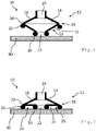
- figure 1 12 shows a cross-sectional view of a suction pad 10 in a non-adhered configuration, in which the suction pad 10 is in contact with an object 90 to be sucked, but not yet sucking it (suction pad 10 is just on the object 90).
- the suction gripper 10 has a suction body 12 .
- the absorbent body 12 is in the example overall elastic and flexible.
- the absorbent body 12 can be formed from an elastomer.
- the absorbent body 12 can also be understood as a wall.
- the absorbent body 12 delimits an absorbent interior 14.
- the absorbent body 12 has a first wall section 16 and a second wall section 18, the wall sections 16, 18 being connected to one another via a fold 20.
- a suction opening 22 is formed, which surrounds the first wall section 16 and through which the suction body 12 is open to the outside, i.e. to the environment.
- the suction opening 22 is arranged in the middle of the first wall section 16 in the example.
- a connecting nipple 24 is arranged on the second wall section 18 .
- the connecting nipple 24 is arranged in the middle of the second wall section 18 in the example.
- the connecting nipple 24 is enclosed in the second wall section 18 .
- a handling device (not shown) can be connected to the connection nipple 24 in order to move the suction gripper 10 . If the suction pad 10 has sucked the object 90, it can also be Handle item 90.
- the first wall section 16 has on its outer side 26 at the suction opening 22 in the example around the first Wall section 16 circumferential, sealing element 30 on. Furthermore, the first wall section 16 has on its outer side 26 at its end 28 facing away from the suction opening 22 a further sealing element 32 running around the first wall section 16 .
- the sealing elements 30, 32 can each be designed as a seal or sealing lip.
- the sealing element 30 at the suction opening 22 can be gas-permeable or air-permeable, for example due to a porous design or due to channels formed in the sealing element 30 (not shown).
- the first wall section 16 itself can also be gas-permeable. Alternatively or additionally, channels can be formed in the first wall section 16, which extend from the outside 26 through the wall section 16 to the suction interior 14 (not shown).
- the first wall section 16 can have adhesion surfaces, friction surfaces, sealing surfaces, microstructures and/or gecko structures on its outer side 26, as explained above (not shown).
- the first wall section 16 can be designed in such a way that (as in the case of a Bernoulli suction gripper) when placed on the object 90 there is a contour on the outside 26 of the first wall section 16 that slopes outwards, starting from the suction opening 22, as explained above ( Not shown).
- the second wall section 18 is stiffer than the first wall section 16, at least in certain areas.
- the second wall section 18 can be designed as a bellows with at least one outer fold and at least one inner fold (not shown).
- Fig.1 an unadhered configuration of the suction gripper 10, in which the suction gripper 10 rests with the suction opening 22 on the object 90 to be sucked up, but does not (yet) suck it up.
- the first wall section 16 has a shell-like shape (cf. Fig.1 ).
- the suction body 12 is flexible enough that when the suction gripper 10 is placed, e.g.
- the first wall section 16 is deformed relative to the suction opening 22 in such a way that the object facing away from the suction opening 22 is deformed End 28 of the first wall section 16 is shifted towards the object 90 to be sucked in, so that the first wall section 16 rests at least in sections on the object 90 to be gripped with its outer side 26 .
- the first wall section 16 has a disk-like shape (cf. Fig.2 ).
- Air that is located between the first wall section 16 and the object 90 to be sucked in is displaced radially outwards, starting from the suction opening 22 .
- a sealing section or a sealing surface 34 is thus formed between the outside 26 of the first wall section 16 and the object 90 .
- the object 90 is thus sucked in by the suction gripper 10 (cf. Fig.2 ).
- FIGS Figures 3 and 4 show a possible embodiment of the suction gripper 10 described above.
- the present suction gripper 10 largely corresponds to that with reference to FIGS Figures 1 and 2 Suction pads 10 described, so that to avoid repetition, reference is made to the explanations given there.
- the first wall section 16 has an extension 36, by means of which the first wall section 16 is extended at least in sections, but in the example completely circumferentially, at the end 28 facing away from the suction opening 22 beyond the fold 20.
- the further sealing element 32 is arranged in the example at the end 28 of the first wall section 16 facing away from the suction opening 22 and is therefore also located in the area of the extension. How based on Fig.3 and 4 recognizable, the resulting sealing section or the sealing surface 34 is enlarged by the extension 36 .
- Attached to extension 36 may be mechanical gripping means for gripping and/or enclosing object 90 to be sucked, as discussed above (not shown).
- channels can be formed in the first wall section 16 which extend from the suction interior 14 to the outside 26 of the extension 36 of the first wall section 16 . In this way, negative pressure can be conducted into the radially outer areas of the first wall section 16 .
- FIG 5 shows a possible embodiment of the with reference to Figures 3 and 4 described suction pad 10.
- the suction pad largely corresponds to the embodiment described above, so that to avoid repetition, reference is made to the explanations there.
- an insert 40 is arranged in the suction opening 22, which closes the suction opening 22 and has a controllable valve or check valve (not shown).
- the insert 40 represents an additional sealing element.
- the insert 40 can optionally have a sensor system, for example a pressure sensor. Flow guidance from the suction interior 14 to the outer surface 26 can also be provided (not shown).
- suction pad 10 can be equipped with an insert 40.
Landscapes
- Engineering & Computer Science (AREA)
- Mechanical Engineering (AREA)
- Robotics (AREA)
- Manipulator (AREA)
- Load-Engaging Elements For Cranes (AREA)
Applications Claiming Priority (1)
| Application Number | Priority Date | Filing Date | Title |
|---|---|---|---|
| DE102021100648.1A DE102021100648B3 (de) | 2021-01-14 | 2021-01-14 | Sauggreifer |
Publications (4)
| Publication Number | Publication Date |
|---|---|
| EP4029664A2 true EP4029664A2 (fr) | 2022-07-20 |
| EP4029664A3 EP4029664A3 (fr) | 2022-10-12 |
| EP4029664C0 EP4029664C0 (fr) | 2024-12-11 |
| EP4029664B1 EP4029664B1 (fr) | 2024-12-11 |
Family
ID=78827317
Family Applications (1)
| Application Number | Title | Priority Date | Filing Date |
|---|---|---|---|
| EP22150900.3A Active EP4029664B1 (fr) | 2021-01-14 | 2022-01-11 | Pince aspirante |
Country Status (3)
| Country | Link |
|---|---|
| EP (1) | EP4029664B1 (fr) |
| CN (1) | CN114763222B (fr) |
| DE (1) | DE102021100648B3 (fr) |
Family Cites Families (12)
| Publication number | Priority date | Publication date | Assignee | Title |
|---|---|---|---|---|
| US2850279A (en) | 1954-03-29 | 1958-09-02 | Miehle Goss Dexter Inc | Sheet separator |
| US4600229A (en) | 1984-08-03 | 1986-07-15 | Oten Peter D | Vacuum cup |
| DE4430381C2 (de) | 1993-08-31 | 1997-02-27 | Smc Kk | Saugpipette |
| JP4547649B2 (ja) | 2000-07-31 | 2010-09-22 | Smc株式会社 | 吸着用パッド |
| NL1024965C2 (nl) | 2003-12-08 | 2005-06-09 | Goudsmit Magnetic Systems B V | Grijpmiddelen en hefinrichting voor het vastpakken en optillen van een voorwerp, in het bijzonder een plaat. |
| DE202008011447U1 (de) * | 2008-08-27 | 2009-01-02 | Herga, Karl | Sauger, Saugerfinger bzw. Saugerhalter oder Saugersystem |
| CN204124820U (zh) * | 2014-10-09 | 2015-01-28 | 刘慨 | 波纹柔性增强吸盘 |
| JP5950995B2 (ja) * | 2014-12-26 | 2016-07-13 | 芙蓉実業株式会社 | 吸着パッド |
| DE102015110074A1 (de) * | 2015-06-23 | 2016-12-29 | Andreas Litke | Vakuumpumpe |
| CN208732099U (zh) * | 2018-05-10 | 2019-04-12 | 广州冠研液压密封有限公司 | 一种真空吸盘 |
| DE102019133542B4 (de) | 2019-12-09 | 2025-04-03 | J. Schmalz Gmbh | Sauggreifer |
| CA3189612A1 (fr) * | 2020-07-22 | 2022-01-27 | Berkshire Grey Operating Company, Inc. | Systemes et procedes de traitement d'objets utilisant un prehenseur a vide qui realise une retention d'objet par mise sous vide |
-
2021
- 2021-01-14 DE DE102021100648.1A patent/DE102021100648B3/de active Active
-
2022
- 2022-01-11 EP EP22150900.3A patent/EP4029664B1/fr active Active
- 2022-01-14 CN CN202210043335.6A patent/CN114763222B/zh active Active
Also Published As
| Publication number | Publication date |
|---|---|
| EP4029664C0 (fr) | 2024-12-11 |
| CN114763222A (zh) | 2022-07-19 |
| DE102021100648B3 (de) | 2021-12-30 |
| EP4029664B1 (fr) | 2024-12-11 |
| EP4029664A3 (fr) | 2022-10-12 |
| CN114763222B (zh) | 2025-08-08 |
Similar Documents
| Publication | Publication Date | Title |
|---|---|---|
| EP2890335B1 (fr) | Manchon prothétique et système d'emboîture de prothèse comprenant un manchon et une emboîture | |
| DE2848433C2 (de) | Sauggerät | |
| DE102019130375B4 (de) | Sauggreiferanordnung zum handhaben von gegenständen | |
| DE102015009998A1 (de) | Sauggreifer für Objekte mit glatten Oberflächen sowie dazugehöriges Verfahren und Verwendung desselben | |
| DE602004012823T2 (de) | Greifmittel zum Anfassen und Aufheben eines Gegenstandes | |
| AT519587B1 (de) | Saugvorrichtung für einen Endeffektor, Endeffektor zum Halten von Substraten sowie Verfahren zur Herstellung eines Endeffektors | |
| EP3496670A1 (fr) | Manchon de prothèse | |
| DE102017124472B3 (de) | Vakuumsaugnapf mit aktiv variierbarer Länge | |
| WO2018130248A1 (fr) | Pompe d'aspiration et dispositif de maintien par succion comprenant une pompe d'aspiration et procédé de montage d'un dispositif de maintien par succion | |
| EP1484142A1 (fr) | Appareil de levage par aspiration muni d'un système cylindre- piston pour produire une dépression | |
| WO2016146140A1 (fr) | Dispositif de préhension | |
| EP4029664B1 (fr) | Pince aspirante | |
| DE102012214178A1 (de) | Anschlussvorrichtung zur Verwendung bei der Unterdrucktherapie von Wunden | |
| DE102012003192A1 (de) | Vakuum-Spannvorrichtung | |
| DE102012214182A1 (de) | Anschlussvorrichtung zur Verwendung bei der Unterdrucktherapie von Wunden | |
| WO2007033830A1 (fr) | Pince aspirante dotee d'un corps aspirant elastique presentant un moyen indiquant l'etat d'aspiration | |
| DE102019133542B4 (de) | Sauggreifer | |
| DE102021106667A1 (de) | Greifvorrichtung | |
| DE69625063T2 (de) | Harninkontinenzvorrichtung für frauen | |
| EP0952106B1 (fr) | Appareil de manipulation à dépression | |
| EP2562104A1 (fr) | Dispositif de retenue par pression négative | |
| DE102011075026A1 (de) | Fluidhandhabungsvorrichtung mit vollständig entleerbarem fluidreservoir | |
| EP4183304B1 (fr) | Interface d'aspiration destinée au raccordement étanche à l'air d'un premier canal d'écoulement à un second canal d'écoulement, station de base pourvue d'interface d'aspiration et système composé d'un appareil de nettoyage par aspiration et d'une station de base | |
| CH679928A5 (fr) | ||
| CH682072A5 (en) | Suction gripper mechanism - has seal sealing it to surface of object to be gripped formed of soft elastic, pref. open-celled foam material |
Legal Events
| Date | Code | Title | Description |
|---|---|---|---|
| PUAI | Public reference made under article 153(3) epc to a published international application that has entered the european phase |
Free format text: ORIGINAL CODE: 0009012 |
|
| STAA | Information on the status of an ep patent application or granted ep patent |
Free format text: STATUS: THE APPLICATION HAS BEEN PUBLISHED |
|
| AK | Designated contracting states |
Kind code of ref document: A2 Designated state(s): AL AT BE BG CH CY CZ DE DK EE ES FI FR GB GR HR HU IE IS IT LI LT LU LV MC MK MT NL NO PL PT RO RS SE SI SK SM TR |
|
| PUAL | Search report despatched |
Free format text: ORIGINAL CODE: 0009013 |
|
| AK | Designated contracting states |
Kind code of ref document: A3 Designated state(s): AL AT BE BG CH CY CZ DE DK EE ES FI FR GB GR HR HU IE IS IT LI LT LU LV MC MK MT NL NO PL PT RO RS SE SI SK SM TR |
|
| RIC1 | Information provided on ipc code assigned before grant |
Ipc: B65G 47/91 20060101ALI20220902BHEP Ipc: B25J 15/06 20060101AFI20220902BHEP |
|
| STAA | Information on the status of an ep patent application or granted ep patent |
Free format text: STATUS: REQUEST FOR EXAMINATION WAS MADE |
|
| 17P | Request for examination filed |
Effective date: 20230202 |
|
| RBV | Designated contracting states (corrected) |
Designated state(s): AL AT BE BG CH CY CZ DE DK EE ES FI FR GB GR HR HU IE IS IT LI LT LU LV MC MK MT NL NO PL PT RO RS SE SI SK SM TR |
|
| GRAP | Despatch of communication of intention to grant a patent |
Free format text: ORIGINAL CODE: EPIDOSNIGR1 |
|
| STAA | Information on the status of an ep patent application or granted ep patent |
Free format text: STATUS: GRANT OF PATENT IS INTENDED |
|
| INTG | Intention to grant announced |
Effective date: 20240710 |
|
| GRAS | Grant fee paid |
Free format text: ORIGINAL CODE: EPIDOSNIGR3 |
|
| GRAA | (expected) grant |
Free format text: ORIGINAL CODE: 0009210 |
|
| STAA | Information on the status of an ep patent application or granted ep patent |
Free format text: STATUS: THE PATENT HAS BEEN GRANTED |
|
| AK | Designated contracting states |
Kind code of ref document: B1 Designated state(s): AL AT BE BG CH CY CZ DE DK EE ES FI FR GB GR HR HU IE IS IT LI LT LU LV MC MK MT NL NO PL PT RO RS SE SI SK SM TR |
|
| REG | Reference to a national code |
Ref country code: GB Ref legal event code: FG4D Free format text: NOT ENGLISH |
|
| REG | Reference to a national code |
Ref country code: CH Ref legal event code: EP |
|
| REG | Reference to a national code |
Ref country code: DE Ref legal event code: R096 Ref document number: 502022002334 Country of ref document: DE |
|
| REG | Reference to a national code |
Ref country code: IE Ref legal event code: FG4D Free format text: LANGUAGE OF EP DOCUMENT: GERMAN |
|
| U01 | Request for unitary effect filed |
Effective date: 20241217 |
|
| U07 | Unitary effect registered |
Designated state(s): AT BE BG DE DK EE FI FR IT LT LU LV MT NL PT RO SE SI Effective date: 20250110 |
|
| U20 | Renewal fee for the european patent with unitary effect paid |
Year of fee payment: 4 Effective date: 20250121 |
|
| PG25 | Lapsed in a contracting state [announced via postgrant information from national office to epo] |
Ref country code: HR Free format text: LAPSE BECAUSE OF FAILURE TO SUBMIT A TRANSLATION OF THE DESCRIPTION OR TO PAY THE FEE WITHIN THE PRESCRIBED TIME-LIMIT Effective date: 20241211 |
|
| PG25 | Lapsed in a contracting state [announced via postgrant information from national office to epo] |
Ref country code: ES Free format text: LAPSE BECAUSE OF FAILURE TO SUBMIT A TRANSLATION OF THE DESCRIPTION OR TO PAY THE FEE WITHIN THE PRESCRIBED TIME-LIMIT Effective date: 20241211 |
|
| PG25 | Lapsed in a contracting state [announced via postgrant information from national office to epo] |
Ref country code: NO Free format text: LAPSE BECAUSE OF FAILURE TO SUBMIT A TRANSLATION OF THE DESCRIPTION OR TO PAY THE FEE WITHIN THE PRESCRIBED TIME-LIMIT Effective date: 20250311 |
|
| PG25 | Lapsed in a contracting state [announced via postgrant information from national office to epo] |
Ref country code: GR Free format text: LAPSE BECAUSE OF FAILURE TO SUBMIT A TRANSLATION OF THE DESCRIPTION OR TO PAY THE FEE WITHIN THE PRESCRIBED TIME-LIMIT Effective date: 20250312 |
|
| PG25 | Lapsed in a contracting state [announced via postgrant information from national office to epo] |
Ref country code: RS Free format text: LAPSE BECAUSE OF FAILURE TO SUBMIT A TRANSLATION OF THE DESCRIPTION OR TO PAY THE FEE WITHIN THE PRESCRIBED TIME-LIMIT Effective date: 20250311 |
|
| PG25 | Lapsed in a contracting state [announced via postgrant information from national office to epo] |
Ref country code: SM Free format text: LAPSE BECAUSE OF FAILURE TO SUBMIT A TRANSLATION OF THE DESCRIPTION OR TO PAY THE FEE WITHIN THE PRESCRIBED TIME-LIMIT Effective date: 20241211 |
|
| PG25 | Lapsed in a contracting state [announced via postgrant information from national office to epo] |
Ref country code: PL Free format text: LAPSE BECAUSE OF FAILURE TO SUBMIT A TRANSLATION OF THE DESCRIPTION OR TO PAY THE FEE WITHIN THE PRESCRIBED TIME-LIMIT Effective date: 20241211 |
|
| PG25 | Lapsed in a contracting state [announced via postgrant information from national office to epo] |
Ref country code: IS Free format text: LAPSE BECAUSE OF FAILURE TO SUBMIT A TRANSLATION OF THE DESCRIPTION OR TO PAY THE FEE WITHIN THE PRESCRIBED TIME-LIMIT Effective date: 20250411 |
|
| PG25 | Lapsed in a contracting state [announced via postgrant information from national office to epo] |
Ref country code: SK Free format text: LAPSE BECAUSE OF FAILURE TO SUBMIT A TRANSLATION OF THE DESCRIPTION OR TO PAY THE FEE WITHIN THE PRESCRIBED TIME-LIMIT Effective date: 20241211 |
|
| PG25 | Lapsed in a contracting state [announced via postgrant information from national office to epo] |
Ref country code: CZ Free format text: LAPSE BECAUSE OF FAILURE TO SUBMIT A TRANSLATION OF THE DESCRIPTION OR TO PAY THE FEE WITHIN THE PRESCRIBED TIME-LIMIT Effective date: 20241211 |
|
| REG | Reference to a national code |
Ref country code: CH Ref legal event code: PL |
|
| PG25 | Lapsed in a contracting state [announced via postgrant information from national office to epo] |
Ref country code: MC Free format text: LAPSE BECAUSE OF FAILURE TO SUBMIT A TRANSLATION OF THE DESCRIPTION OR TO PAY THE FEE WITHIN THE PRESCRIBED TIME-LIMIT Effective date: 20241211 |
|
| PLBE | No opposition filed within time limit |
Free format text: ORIGINAL CODE: 0009261 |
|
| STAA | Information on the status of an ep patent application or granted ep patent |
Free format text: STATUS: NO OPPOSITION FILED WITHIN TIME LIMIT |
|
| PG25 | Lapsed in a contracting state [announced via postgrant information from national office to epo] |
Ref country code: CH Free format text: LAPSE BECAUSE OF NON-PAYMENT OF DUE FEES Effective date: 20250131 |
|
| 26N | No opposition filed |
Effective date: 20250912 |
|
| PG25 | Lapsed in a contracting state [announced via postgrant information from national office to epo] |
Ref country code: IE Free format text: LAPSE BECAUSE OF NON-PAYMENT OF DUE FEES Effective date: 20250111 |
|
| U20 | Renewal fee for the european patent with unitary effect paid |
Year of fee payment: 5 Effective date: 20260119 |