EP4029357B1 - Elektrogerät und verfahren zum herstellen eines ersten und zweiten elektrogeräts aus einem baukasten - Google Patents
Elektrogerät und verfahren zum herstellen eines ersten und zweiten elektrogeräts aus einem baukasten Download PDFInfo
- Publication number
- EP4029357B1 EP4029357B1 EP20768502.5A EP20768502A EP4029357B1 EP 4029357 B1 EP4029357 B1 EP 4029357B1 EP 20768502 A EP20768502 A EP 20768502A EP 4029357 B1 EP4029357 B1 EP 4029357B1
- Authority
- EP
- European Patent Office
- Prior art keywords
- power module
- contact surface
- electrical device
- frame part
- circuit board
- Prior art date
- Legal status (The legal status is an assumption and is not a legal conclusion. Google has not performed a legal analysis and makes no representation as to the accuracy of the status listed.)
- Active
Links
Images


Classifications
-
- H—ELECTRICITY
- H05—ELECTRIC TECHNIQUES NOT OTHERWISE PROVIDED FOR
- H05K—PRINTED CIRCUITS; CASINGS OR CONSTRUCTIONAL DETAILS OF ELECTRIC APPARATUS; MANUFACTURE OF ASSEMBLAGES OF ELECTRICAL COMPONENTS
- H05K7/00—Constructional details common to different types of electric apparatus
- H05K7/20—Modifications to facilitate cooling, ventilating, or heating
- H05K7/2089—Modifications to facilitate cooling, ventilating, or heating for power electronics, e.g. for inverters for controlling motor
- H05K7/209—Heat transfer by conduction from internal heat source to heat radiating structure
-
- H—ELECTRICITY
- H02—GENERATION; CONVERSION OR DISTRIBUTION OF ELECTRIC POWER
- H02M—APPARATUS FOR CONVERSION BETWEEN AC AND AC, BETWEEN AC AND DC, OR BETWEEN DC AND DC, AND FOR USE WITH MAINS OR SIMILAR POWER SUPPLY SYSTEMS; CONVERSION OF DC OR AC INPUT POWER INTO SURGE OUTPUT POWER; CONTROL OR REGULATION THEREOF
- H02M1/00—Details of apparatus for conversion
-
- H—ELECTRICITY
- H02—GENERATION; CONVERSION OR DISTRIBUTION OF ELECTRIC POWER
- H02M—APPARATUS FOR CONVERSION BETWEEN AC AND AC, BETWEEN AC AND DC, OR BETWEEN DC AND DC, AND FOR USE WITH MAINS OR SIMILAR POWER SUPPLY SYSTEMS; CONVERSION OF DC OR AC INPUT POWER INTO SURGE OUTPUT POWER; CONTROL OR REGULATION THEREOF
- H02M7/00—Conversion of AC power input into DC power output; Conversion of DC power input into AC power output
- H02M7/003—Constructional details, e.g. physical layout, assembly, wiring or busbar connections
-
- H—ELECTRICITY
- H05—ELECTRIC TECHNIQUES NOT OTHERWISE PROVIDED FOR
- H05K—PRINTED CIRCUITS; CASINGS OR CONSTRUCTIONAL DETAILS OF ELECTRIC APPARATUS; MANUFACTURE OF ASSEMBLAGES OF ELECTRICAL COMPONENTS
- H05K1/00—Printed circuits
- H05K1/02—Details
- H05K1/0201—Thermal arrangements, e.g. for cooling, heating or preventing overheating
- H05K1/0203—Cooling of mounted components
-
- H—ELECTRICITY
- H05—ELECTRIC TECHNIQUES NOT OTHERWISE PROVIDED FOR
- H05K—PRINTED CIRCUITS; CASINGS OR CONSTRUCTIONAL DETAILS OF ELECTRIC APPARATUS; MANUFACTURE OF ASSEMBLAGES OF ELECTRICAL COMPONENTS
- H05K7/00—Constructional details common to different types of electric apparatus
- H05K7/20—Modifications to facilitate cooling, ventilating, or heating
- H05K7/2089—Modifications to facilitate cooling, ventilating, or heating for power electronics, e.g. for inverters for controlling motor
- H05K7/20909—Forced ventilation, e.g. on heat dissipaters coupled to components
Definitions
- the invention relates to an electrical device and a method for producing a first and a second electrical device from a modular system.
- the invention is therefore based on the object of designing an electrical device that can be produced cost-effectively.
- the object is achieved in the electrical device according to the features specified in claim 1 and in the method according to the features specified in claim 13.
- the advantage here is that a wide variety of electrical devices can be manufactured from a kit with only a small number of components.
- a smaller power module can be placed on the contact surface than can be arranged on the contact surface if the frame part is omitted.
- the power module is electrically connected to a circuit board arranged on the side of the power module facing away from the contact surface,
- contacts of the power module are pressed onto conductor tracks of the circuit board for electrical contact.
- the advantage here is that electrical contact is made by pressing the circuit board onto the spring-loaded or mounted contacts of the power module. No soldering connection is therefore necessary and the power module can thus be arranged on the contact surface in a first manufacturing step and, in a subsequent second manufacturing step, the circuit board can be placed and screwed onto the heat sink and/or a holding plate can be placed on the circuit board and pressed on using a screw head that is screwed into a threaded hole in the power module.
- the power module can be positioned relative to the circuit board using protruding positioning pins molded onto the power module, with the positioning pins and the screw passing through respective recesses in the circuit board.
- a holding plate is arranged on the side of the circuit board facing away from the power module, which is pressed onto the circuit board, in particular by a screw head of a screw that is at least partially screwed into a threaded hole in the power module, in particular which is thus pressed onto the power module.
- the frame part has protruding projections, in particular noses, on its inner side towards the power module, in particular, where several of the projections touch the power module.
- the projections allow approximately point contact and are resilient are arranged. This allows elastic centering of the power module on the contact surface.
- the power module is accommodated on the inside of the frame part and the outside of the frame part is accommodated by the heat sink, in particular by the bead.
- the frame part is arranged between the bead that runs intermittently around the contact surface and the power module.
- the frame part itself is thus placed on the contact surface by means of positioning pin areas, supported on the circuit board and receives and centers the power module.
- the frame part itself is in turn supported on the bead that runs intermittently around the contact surface by means of projections that enable point contact.
- the bead is therefore not continuous in the circumferential direction around the contact surface, but with interruptions.
- each of the projections is formed on a respective web which delimits a respective slot, in particular, the respective slot is less extensive in the direction from the slot to the projection than in the direction perpendicular to the direction.
- the frame part has a positioning pin area which is fixed to the circuit board, in particular on the side of the circuit board facing away from the holding plate. circuit board.
- the frame part has two slots spaced apart from one another on at least one shortest connecting line between the power module and the bead, in particular wherein a first of the two slots is arranged closer to the power module than the second of the two slots. It is advantageous that the slots are longitudinal slots which are aligned parallel to the surface closest to them.
- the power module has controllable semiconductor switches, in particular IGBT or MOSFET, of an inverter.
- controllable semiconductor switches in particular IGBT or MOSFET.
- the bead is spaced from the circuit board and the power module touches both the heat sink, in particular the contact surface of the heat sink, and also the circuit board.
- the power module is easily centered.
- the contact surface is flat. The advantage here is that a low heat transfer resistance can be achieved between the contact surface and the power module.
- the contact surface is aligned parallel to the circuit board, in particular, the positioning pins are aligned perpendicular to the contact surface.
- the positioning pins are subjected to pressure in the normal direction of the circuit board plane.
- a cooling air flow conveyed by a fan is guided along the side of the heat sink facing away from the contact surface.
- components of a signal electronics system are arranged on the side of the circuit board facing away from the power module, with the signal electronics system generating control signals to control the controllable semiconductor switches of the power module.
- the signal electronics system is thermally separated from the power module by means of the circuit board, which acts as a thermal barrier or at least as a thermal resistor.
- the base material of the circuit board has a considerable thermal resistance, which is, however, reduced by means of through-holes.
- a thermal resistor is implemented by means of the circuit board, which causes a temperature gradient between the power module and the spatial area of the signal electronics system.
- the advantage here is that a high variety of electrical devices can be manufactured from a small number of components in a modular system.
- the small frame part allows the smaller first power module to be arranged on the same contact surface of the heat sink as the second power module.
- the frame part can be manufactured inexpensively as a plastic injection-molded part and is therefore negligible in terms of costs.
- only one type of heat sink is required in the modular system, and therefore also in the warehouse of the system for manufacturing electrical devices. This means that the number of heat sinks is large and the heat sinks can be manufactured inexpensively.
- the area of the contact surface where the first power module touches the contact surface has a smaller surface area than the area of the contact surface where the second power module touches the contact surface.
- the converter has a housing 1 which is connected to a heat sink 3 which has a flat, in particular finely machined, contact surface arranged towards the interior.
- the contact surface is aligned parallel to the circuit board 6, which is spaced from the contact surface.
- protruding limiting knobs 25 are formed on the heat sink 3. These limiting knobs 25 protrude upwards, i.e. towards the circuit board 6.
- a frame part 4 is placed on the contact surface.
- the frame part 4 is designed as a rectangular frame and has longitudinal slots running through it in the normal direction of a plane receiving the circuit board, so that the frame part 4 has only a small amount of material in the area surrounding the longitudinal slots, which can thus be elastically deflected in a direction perpendicular to the normal direction and the slot direction.
- the respective longitudinal slot is delimited by a thin web of the material, wherein the web lies on the inner edge of the frame part if the associated slot region is arranged closer to the inner than to the outer edge of the frame part, and has an inwardly projecting projection 21, in particular a nose.
- the web rests on the outer edge of the frame part 4 and has an outwardly directed projection 23, in particular a nose.
- a bead rises in the normal direction, at least in sections, which is, however, surmounted by the limiting knobs 25.
- the bead rises in the normal direction at least equal to or more than the wall thickness of the frame part 4 in this normal direction.
- the frame part 4 is thus limited at its peripheral edge. To limit it in the normal direction, positioning pin areas 22 are formed on the frame part 4, which are supported on the circuit board 6.
- the frame part 4 touches the heat sink 3, wherein the projections 23 are supported on the bead of the heat sink 3.
- the projections 23 are formed on the webs delimiting the longitudinal slots and are thus arranged elastically springy on the frame part 4.
- the frame part 4 is fixed between the contact surface of the heat sink 3 and the circuit board 6 in all spatial directions.
- the power module 5 has controllable semiconductor switches of an inverter, which is intended to supply an electric motor.
- the controllable semiconductor switches are arranged in half-bridges connected in parallel to one another and are supplied from a direct voltage, in particular intermediate circuit voltage.
- Each of the half-bridges provides a respective one of the phase voltages of the alternating voltage, in particular three-phase voltage, provided by the inverter to the motor at its center tap.
- the power module 5 is accommodated in the interior of the frame part 4, so that the power module 5 is surrounded by the frame part 4 in the directions perpendicular to the normal direction, wherein the power module 5 projects beyond the frame part 4 in the normal direction.
- the power module 5 is placed on the contact surface, in particular with thermal paste arranged between them.
- the power module 5 On its side facing away from the contact surface, the power module 5 has a positioning pin 20 which projects through a corresponding recess, in particular through a hole, in the circuit board 6 into a recess in the holding plate 2 and thus positions the power module 5 relative to the circuit board 6.
- the retaining plate 2 arranged on the side of the circuit board 6 facing away from the power module 5 is screwed into a threaded hole in the power module 5 with a screw which protrudes through the circuit board 6.
- the screw head then presses the retaining plate 2 onto the circuit board 6 and this onto the side of the power module 5 facing away from the contact surface.
- the circuit board 6 and the power module are thus also pressed onto one another.
- the frame part 4 has at least one discrete rotational symmetry about an axis with a rotation angle of 180°, wherein the axis is aligned parallel to the normal direction and passes through the center of gravity of the frame part 4.
- the projections (21, 23) are each arranged on a respective web which delimits a respective slot, wherein the slot has its smallest extent in the direction from the slot to the associated projection and its greatest extent perpendicular thereto, in particular in the transverse direction.
- the housing 1 and the heat sink 3 are designed as one piece, in particular as an aluminum casting.
- a larger power module is used in comparison to the power module 5, so that no frame part 4 is necessary and the power module can be placed directly on the contact surface and the protruding limiting knobs 25 formed on the heat sink 3 at the edge of the contact surface limit and/or center the power module.
- the converter is only designed as an inverter, i.e. it has a DC voltage connection for supplying the controllable semiconductor switches of the power module. If necessary, unused rectifier diodes are arranged on the power module for rectifying the voltage of an AC voltage supply network.
- the converter or inverter other electrical devices with a power module are also included in the invention.
Landscapes
- Engineering & Computer Science (AREA)
- Microelectronics & Electronic Packaging (AREA)
- Physics & Mathematics (AREA)
- Thermal Sciences (AREA)
- Power Engineering (AREA)
- Inverter Devices (AREA)
- Cooling Or The Like Of Electrical Apparatus (AREA)
- Cooling Or The Like Of Semiconductors Or Solid State Devices (AREA)
Description
- Die Erfindung betrifft ein Elektrogerät und ein Verfahren zum Herstellen eines ersten und zweiten Elektrogeräts aus einem Baukasten.
- Elektrogeräte mit Kühlkörper sind allgemein bekannt.
- Aus der
US 2004 / 0 252 461 A1 ist hierzu ist eine Kühlanordnung mit Befestigungsrahmen bekannt. - Aus der
US 2001 / 0 026 440 A1 ist eine Anordnung zum Abschirmen unerwünschter elektromagnetischer Strahlung bekannt. - Aus der
US 6 639 800 B1 ist eine Kühlanordnung mit mehreren Befestigungspunkten bekannt. - Aus der
DE 10 2019 001 113 A1 ist eine Elektrogeräteanordnung, aufweisend ein an einem Tragelement befestigbares Elektrogerät, bekannt. - Aus der
DE 20 2008 001 996 U1 ist eine Positionierungsvorrichtung für Wärmesenke bekannt. - Aus der
US 6 442 045 B1 ist eine Kühlanordnung für einen integrierten Schaltkreis bekannt. - Aus der
US 837 753 S ist eine Wärmesenke bekannt. - Aus der
DE 10 2011 010 429 A1 ist ein elektrisches Gerät, insbesondere Umrichter, bekannt. - Aus der
US 7 952 879 B1 ist als nächstliegender Stand der Technik ist ein System für effizientes Entwärmen eines Elektronikmoduls bekannt. - Aus der
US 2007/258194 A1 ist eine Motorsteuerung bekannt. - Aus der
US 2003/000080 A1 ist ein Halteteil für die Installation eines Multichipmoduls bekannt. - Aus der
JP 2014 110734 A - Der Erfindung liegt daher die Aufgabe zugrunde, ein Elektrogerät kostengünstig herstellbar auszubilden.
- Erfindungsgemäß wird die Aufgabe bei dem Elektrogerät nach den in Anspruch 1 und bei dem Verfahren nach den in Anspruch 13 angegebenen Merkmalen gelöst.
- Wichtige Merkmale der Erfindung bei dem Elektrogerät, insbesondere Wechselrichter oder Umrichter, sind, dass das Elektrogerät einen eine Kontaktfläche aufweisenden Kühlkörper aufweist, auf welchem ein Leistungsmodul angeordnet ist, insbesondere mit zwischen Kontaktfläche und Leistungsmodul zwischengeordneter Wärmeleitpaste,
- wobei ein Rahmenteil des Elektrogeräts auf der Kontaktfläche angeordnet, insbesondere aufgelegt ist, wobei das Leistungsmodul im Rahmenteil aufgenommen ist,
- wobei das Rahmenteil durch einen am Rand der Kontaktfläche hervorragenden Wulst des Kühlkörpers begrenzt ist,
- insbesondere wobei der Kühlkörper metallisch und das Rahmenteil aus Kunststoff, insbesondere als Spritzgussteil, ausgeführt ist.
- Von Vorteil ist dabei, dass eine große Varianz von Elektrogeräten aus einem Baukasten mit nur einer geringen Anzahl von Komponenten herstellbar ist. Indem ein Rahmenteil verwendet wird, ist ein kleineres Leistungsmodul auf der Kontaktfläche aufbringbar als bei Weglassen des Rahmenteils auf der Kontaktfläche anordenbar ist.
- Bei einer vorteilhaften Ausgestaltung ist das Leistungsmodul mit einer auf der von der Kontaktfläche abgewandten Seite des Leistungsmoduls angeordneten Leiterplatte elektrisch verbunden,
- insbesondere wobei Kontakte des Leistungsmoduls zur elektrischen Kontaktierung auf Leiterbahnen der Leiterplatte gedrückt angeordnet sind. Von Vorteil ist dabei, dass durch Andrücken der Leiterplatte an die federnd ausgeführten oder gelagerten Kontakte des Leistungsmoduls die elektrische Kontaktierung bewirkt wird. Es ist also keine Lötverbindung notwendig und somit ist das Leistungsmodul in einem ersten Herstellschritt auf der Kontaktfläche anordenbar und in einem nachfolgenden zweiten Herstellverfahrensschritt die Leiterplatte aufsetzbar und am Kühlkörper anschraubbar und/oder eine Halteplatte auf die Leiterplatte aufsetzbar und mittels eines Schraubenkopfes einer Schraube andrückbar, welche in eine Gewindebohrung des Leistungsmoduls eingeschraubt wird. Dabei ist das Leistungsmodul mittels am Leistungsmodul angeformter und hervorstehender Positionierstifte relativ zur Leiterplatte positionierbar, wobei die Positionierstifte wie auch die Schraube durch jeweilige Ausnehmungen der Leiterplatte hindurchgehen.
- Bei einer vorteilhaften Ausgestaltung ist auf der von dem Leistungsmodul abgewandten Seite der Leiterplatte eine Halteplatte angeordnet, welche, insbesondere von einem Schraubenkopf einer in eine Gewindebohrung des Leistungsmoduls, zumindest teilweise eingeschraubten Schraube auf die Leiterplatte gedrückt wird, insbesondere welche somit auf das Leistungsmodul gedrückt wird. Von Vorteil ist dabei, dass ein Andrücken der Kontakte des Leistungsmoduls an Leiterbahnen der Leiterplatte in einfacher Weise ermöglicht ist.
- Bei einer vorteilhaften Ausgestaltung weist das Rahmenteil an seiner Innenseite zum Leistungsmodul hin hervorragende Vorsprünge, insbesondere Nasen, auf,
insbesondere wobei mehrere der Vorsprünge das Leistungsmodul berühren. Von Vorteil ist dabei, dass die Vorsprünge näherungsweise Punktberührung ermöglichen und federnd angeordnet sind. Somit ist ein elastisches Zentrieren des Leistungsmodules an der Kontaktfläche ausführbar. - Bei einer vorteilhaften Ausgestaltung ist das Leistungsmodul an der Innenseite des Rahmenteils aufgenommen und die Außenseite des Rahmenteils vom Kühlkörper, insbesondere vom Wulst, aufgenommen. Von Vorteil ist dabei, dass das Rahmenteil zwischengeordnet ist zwischen dem um die Kontaktfläche unterbrochen umlaufenden Wulst und dem Leistungsmodul. Somit ist das Rahmenteil selbst aufgelegt auf der Kontaktfläche mittels Positionierstiftbereichen abgestützt an der Leiterplatte und nimmt das Leistungsmodul auf und zentriert es. Selbst wiederum ist das Rahmenteil mittels ebensolcher Punktberührung ermöglichenden Vorsprünge am unterbrochen um die Kontaktfläche umlaufenden Wulst abgestützt. Der Wulst ist also in Umfangsrichtung um die Kontaktfläche herum nicht ununterbrochen ausgeführt, sondern mit Unterbrechungen.
- Bei einer vorteilhaften Ausgestaltung ist jeder der Vorsprünge an einem jeweiligen Steg angeformt, welcher einen jeweiligen Schlitz begrenzt,
insbesondere wobei der jeweilige Schlitz in der vom Schlitz zum Vorsprung gerichteten Richtung weniger ausgedehnt ist als in der zur Richtung senkrechten Richtung. Von Vorteil ist dabei, dass der Steg dünn ist und somit elastisch verformbar, so dass der Vorsprung ebenfalls elastisch verformbar ist. - Bei einer vorteilhaften Ausgestaltung weist das Rahmenteil an seiner Außenseite zum am Kühlkörper ausgeformten Wulst hin hervorragende Vorsprünge, insbesondere Nasen, auf,
- insbesondere wobei mehrere dieser Vorsprünge den Wulst berühren,
- insbesondere wobei der Wulst mehrstückig, also mehrteilig, ausgebildet ist. Von Vorteil ist dabei, dass die Vorsprünge elastisch gefedert angeordnet sind und somit die Zentrierung elastisch bewirken.
- Bei einer vorteilhaften Ausgestaltung weist das Rahmenteil einen Positionierstiftbereich auf, welcher an der Leiterplatte, insbesondere an der von der Halteplatte abgewandten Seite der Leiterplatte, abgestützt ist. Von Vorteil ist dabei, dass das Rahmenteil in allen Raumrichtungen begrenzt angeordnet ist.
- Bei einer vorteilhaften Ausgestaltung weist das Rahmenteil auf zumindest einer kürzesten Verbindungslinie zwischen dem Leistungsmodul und dem Wulst zwei voneinander beabstandete Schlitze auf, insbesondere wobei ein erster der beiden Schlitze näher am Leistungsmodul als der zweite der beiden Schlitze angeordnet ist. Von Vorteil ist dabei, dass die Schlitze Längsschlitze sind, welche parallel zu der ihnen nächstliegenden Oberfläche ausgerichtet sind.
- Bei einer vorteilhaften Ausgestaltung weist das Leistungsmodul steuerbare Halbleiterschalter, insbesondere IGBT oder MOSFET, auf, eines Wechselrichters aufweist. Von Vorteil ist dabei, dass dem Motor eine Drehspannung zur Verfügung stellbar ist.
- Bei einer vorteilhaften Ausgestaltung ist der Wulst von der Leiterplatte beabstandet und das Leistungsmodul sowohl den Kühlkörper, insbesondere die Kontaktfläche des Kühlkörpers, berührt also auch die Leiterplatte. Von Vorteil ist dabei, dass das Leistungsmodul in einfacher Weise zentriert ist.
- Bei einer vorteilhaften Ausgestaltung ist die Kontaktfläche eben ausgeführt. Von Vorteil ist dabei, dass ein niedriger Wärmeübergangswiderstand zwischen Kontaktfläche und Leistungsmodul erreichbar ist.
- Bei einer vorteilhaften Ausgestaltung ist die Kontaktfläche parallel zur Leiterplatte ausgerichtet,
insbesondere wobei die Positionierstifte senkrecht zur Kontaktfläche ausgerichtet sind. Von Vorteil ist dabei, dass die Positionierstifte in Normalenrichtung der Leiterplattenebene auf Druck belastet sind. - Bei einer vorteilhaften Ausgestaltung wird ein von einem Lüfter geförderter Kühlluftstrom an der von der Kontaktfläche abgewandten Seite des Kühlkörpers entlanggeführt. Von Vorteil ist dabei, dass eine effiziente Kühlung der Wärme erzeugenden Leistungsmoduls erreichbar ist, da die Wärme auf der anderen Seite mittels des geförderten Luftstroms abgeführt wird an die Umgebungsluft.
- Bei einer vorteilhaften Ausgestaltung sind Bauelemente einer Signalelektronik auf der vom Leistungsmodul abgewandten Seite der Leiterplatte angeordnet, wobei die Signalelektronik Ansteuersignale erzeugt zur Ansteuerung der steuerbaren Halbleiterschalter des Leistungsmoduls. Von Vorteil ist dabei, dass die Signalelektronik thermisch getrennt ist von dem Leistungsmodul mittels der als Wärmesperre oder zumindest als Wärmewiderstand fungierenden Leiterplatte. Insbesondere das Grundmaterial der Leiterplatte weist einen erheblichen Wärmewiderstand auf, der allerdings mittels Durchkontaktierungen verringert wird. Trotzdem ist mittels der Leiterplatte ein Wärmewiderstand realisiert, der ein Temperaturgefälle zwischen Leistungsmodul und Raumbereich der Signalelektronik bewirkt.
- Wichtige Merkmale bei dem Verfahren zum Herstellen eines ersten und zweiten Elektrogeräts aus einem Baukasten sind, dass wahlweise
- entweder das erste Elektrogerät aus dem Rahmenteil, dem Kühlkörper und dem ersten Leistungsmodul hergestellt wird
- oder das zweite Elektrogerät aus dem zweiten Leistungsmodul und dem Kühlkörper hergestellt wird,
- insbesondere wobei der Baukasten ein erstes und ein zweites Leistungsmodul aufweist, ein Rahmenteil und einen Kühlkörper, der eine Kontaktfläche aufweist,
- insbesondere wobei das jeweilige Elektrogerät ein jeweiliger Wechselrichter oder Umrichter ist,
- (i) wobei zur Herstellung des ersten Elektrogeräts auf dem die Kontaktfläche aufweisenden Kühlkörper das erste Leistungsmodul angeordnet wird, insbesondere mit zwischen Kontaktfläche und erstem Leistungsmodul zwischengeordneter Wärmeleitpaste,
- wobei das Rahmenteil auf der Kontaktfläche angeordnet wird, insbesondere aufgelegt wird, wobei das erste Leistungsmodul im Rahmenteil aufgenommen wird,
- wobei das Rahmenteil durch einen am Rand der Kontaktfläche hervorragenden Wulst des Kühlkörpers begrenzt wird,
- (ii) wobei zur Herstellung des zweiten Elektrogeräts auf dem die Kontaktfläche aufweisenden Kühlkörper, dass weite Leistungsmodul angeordnet wird, insbesondere mit zwischen Kontaktfläche und Leistungsmodul zwischengeordneter Wärmeleitpaste,
- wobei das zweite Leistungsmodul durch den am Rand der Kontaktfläche hervorragenden Wulst des Kühlkörpers begrenzt wird.
- Von Vorteil ist dabei, dass eine hohe Varianz von Elektrogeräten aus einer geringen Anzahl von Komponenten eines Baukastens herstellbar ist. Denn mittels des kleinen Rahmenteils ist das kleinere erste Leistungsmodul auf derselben Kontaktfläche des Kühlkörpers anordenbar wie das zweite Leistungsmodul. Das Rahmenteil ist als Kunststoffspritzgussteil kostengünstig ausführbar und somit von den Kosten her vernachlässigbar. Im Baukasten, also auch im Lager der Anlage zum Fertigen der Elektrogeräte, ist jedoch nur eine einzige Sorte von Kühlkörpern vorzusehen. Somit sind die Stückzahlen der Kühlkörper groß und somit die Kühlkörper kostengünstig herstellbar.
- Bei einer vorteilhaften Ausgestaltung weist derjenige Flächenbereich der Kontaktfläche, an welcher das erste Leistungsmodul die Kontaktfläche berührt, einen kleineren Flächeninhalt auf als derjenige Flächenbereich der Kontaktfläche, an welcher das zweite Leistungsmodul die Kontaktfläche berührt. Von Vorteil ist dabei, dass wahlweise zwei verschieden große Leistungsmodule auf derselben Kontaktfläche anordenbar sind. Somit ist im Baukasten zur Herstellung der Baureihe von Elektrogeräten nur eine Art von Kühlkörper zu bevorraten, also für das Leistungsmodul kleinerer Baugröße ist derselbe Kühlkörper verwendbar, der eigentlich für ein Leistungsmodul größerer Baugröße verwendbar ist.
- Weitere Vorteile ergeben sich aus den Unteransprüchen. Die Erfindung ist nicht auf die Merkmalskombination der Ansprüche beschränkt. Für den Fachmann ergeben sich weitere sinnvolle Kombinationsmöglichkeiten von Ansprüchen und/oder einzelnen Anspruchsmerkmalen und/oder Merkmalen der Beschreibung und/oder der Figuren, insbesondere aus der Aufgabenstellung und/oder der sich durch Vergleich mit dem Stand der Technik stellenden Aufgabe.
- Die Erfindung wird nun anhand von schematischen Abbildungen näher erläutert:
- In der
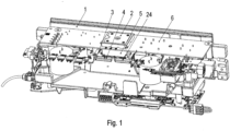
Figur 1 ist ein erfindungsgemäßer Umrichter angeschnitten in Schrägansicht dargestellt, der ein Leistungsmodul 5, ein Rahmenteil 4 und eine Leiterplatte 6 aufweist. - In der
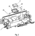
Figur 2 ist das Leistungsmodul 5, das Rahmenteil 4 am Umrichter explodiert in Schrägansicht dargestellt, wobei die Leiterplatte 6 ausgeblendet ist. - In der
Figur 3 ist der angeschnittene Umrichter in Schrägansicht dargestellt, wobei die Leiterplatte 6 ausgeblendet ist. - In der
Figur 4 ist das Rahmenteil 4 in Draufsicht dargestellt. - In der
Figur 5 ist das Rahmenteil 4 in Schrägansicht dargestellt. - Wie in den Figuren dargestellt, weist der Umrichter ein Gehäuse 1 auf, das mit einem Kühlkörper 3 verbunden ist, der eine zum Innenraum hin angeordnete ebene, insbesondere fein bearbeitete, Kontaktfläche aufweist.
- Die Kontaktfläche ist parallel zu der Leiterplatte 6 ausgerichtet, welche beabstandet ist von der Kontaktfläche.
- Am Rand der insbesondere im Wesentlichen als Rechteck ausgeführten Kontaktfläche sind am Kühlkörper 3 hervorstehende Begrenzungsnoppen 25 ausgeformt. Diese Begrenzungsnoppen 25 stehen nach oben, also zur Leiterplatte 6 hin, hervor.
- Auf die Kontaktfläche ist ein Rahmenteil 4 aufgelegt. Das Rahmenteil 4 ist als Rechteckrahmen ausgeführt und weist dabei in Normalenrichtung einer die Leiterplatte aufnehmenden Ebene durchgehende Längsschlitze auf, so dass das Rahmenteil 4 im die Längsschlitze umgebenden Bereich nur wenig Material aufweist, das somit elastisch in zur Normalenrichtung und zur Schlitzrichtung senkrechten Richtung auslenkbar ist.
- Der jeweilige Längsschlitz ist von einem dünnen Steg des Materials begrenzt, wobei der Steg am inneren Rand des Rahmenteils liegt, wenn der zugehörige Schlitzbereich näher am inneren als am äußeren Rand des Rahmenteils angeordnet ist, und einen nach innen vorstehenden Vorsprung 21, insbesondere Nase, aufweist.
- Wenn der jeweilige Schlitzbereich jedoch näher am äußeren als am inneren Rand des Rahmenteils angeordnet ist, liegt der Steg am äußeren Rand des Rahmenteils 4 an und weist einen nach außen gerichteten Vorsprung 23, insbesondere Nase, auf.
- Am Rand der Kontaktfläche erhebt sich in Normalenrichtung zumindest abschnittsweise ein Wulst, der allerdings von den Begrenzungsnoppen 25 überragt wird.
- Der Wulst erhebt sich in Normalenrichtung zumindest gleich oder mehr als die Wandstärke des Rahmenteils 4 in dieser Normalenrichtung beträgt.
- Somit ist das Rahmenteil 4 an seinem umlaufenden Rand begrenzt. Zur Begrenzung in Normalenrichtung sind am Rahmenteil 4 Positionierstiftbereiche 22 ausgeformt, welche sich an der Leiterplatte 6 abstützen.
- Mittels der Vorsprünge 23 berührt das Rahmenteil 4 den Kühlkörper 3, wobei die Vorsprünge 23 am Wulst des Kühlkörpers 3 abgestützt sind. Die Vorsprünge 23 sind an den die Längsschlitze begrenzenden Stegen ausgeformt und somit elastisch federnd am Rahmenteil 4 angeordnet.
- Somit ist das Rahmenteil 4 zwischen der Kontaktfläche des Kühlkörpers 3 und der Leiterplatte 6 in allen Raumrichtungen fixiert.
- Das Leistungsmodul 5 weist steuerbare Halbleiterschalter eines Wechselrichters auf, welcher zur Speisung eines Elektromotors vorgesehen ist. Die steuerbaren Halbleiterschalter sind in zueinander parallel geschalteten Halbbrücken angeordnet und werden aus einer Gleichspannung, insbesondere Zwischenkreisspannnung, versorgt. Jede der Halbbrücken stellt an ihrer Mittelanzapfung eine jeweilige der Phasenspannungen der vom Wechselrichter bereit gestellten Wechselspannung, insbesondere Drehspannung, dem Motor zur Verfügung.
- Das Leistungsmodul 5 ist im Innenbereich des Rahmenteils 4 aufgenommen, so dass das Leistungsmodul 5 in den zur Normalenrichtung senkrechten Richtungen vom Rahmenteil 4 umgeben ist, wobei das Leistungsmodul 5 das Rahmenteil 4 in Normalenrichtung überragt.
- Das Leistungsmodul 5 ist auf der Kontaktfläche aufgesetzt, insbesondere mit zwischengeordneter Wärmeleitpaste.
- Die an der Innenseite des Rahmenteils 4 nach innen zum Leistungsmodul 5 hervorragenden Vorsprünge 21, insbesondere Nasen, berühren das Leistungsmodul 5 und tragen zur Positionierung des Leistungsmoduls 5 bei.
- An seiner von der Kontaktfläche abgewandten Seite weist das Leistungsmodul 5 einen Positionierstift 20 auf, der durch eine entsprechende Ausnehmung, insbesondere durch ein Loch, der Leiterplatte 6 hindurch in eine Ausnehmung der Halteplatte 2 hineinragt und somit das Leistungsmodul 5 zur Leiterplatte 6 relativ positioniert.
- Die auf der vom Leistungsmodul 5 abgewandten Seite der Leiterplatte 6 angeordnete Halteplatte 2 wird mit einer Schraube, welche durch die Leiterplatte 6 hindurchragt, in eine Gewindebohrung des Leistungsmoduls 5 eingeschraubt. Dabei drückt dann der Schraubenkopf der Schraube die Halteplatte 2 auf die Leiterplatte 6 und diese auf die von der Kontaktfläche abgewandte Seite des Leistungsmoduls 5. Somit werden also auch die Leiterplatte 6 und das Leistungsmodul aufeinandergedrückt.
- Das Rahmenteil 4 weist zumindest eine diskrete Drehsymmetrie um eine Achse auf mit einem Drehwinkel von 180°, wobei die Achse parallel zur Normalenrichtung ausgerichtet ist und durch den Schwerpunkt des Rahmenteils 4 hindurchgeht.
- Wie in
Figur 4 deutlich gezeigt, sind die Vorsprünge (21, 23) jeweils an einem jeweiligen Steg angeordnet, der einen jeweiligen Schlitz begrenzt, wobei der Schlitz in der vom Schlitz zum zugehörigen Vorsprung hin gerichteten Richtung seine geringste Ausdehnung und senkrecht dazu, insbesondere also in Querrichtung, seine größte Ausdehnung aufweist. - Nicht alle Vorsprünge 23 liegen am Wulst an, insbesondere da der Wulst in Umfangsrichtung nicht ununterbrochen, sondern mit Unterbrechungen umläuft. Somit ist das Rahmenteil 4 auch
- für andere Umrichter verwendbar, wo dann die im in den Figuren ungenutzten Vorsprünge 23 genutzt werden, also am dann anders ausgeformten Wulst anliegen.
- Bei weiteren erfindungsgemäßen Ausführungsbeispielen wird das Gehäuse 1 und der Kühlkörper 3 einstückig, also einteilig ausgeführt, insbesondere als Aluminium-Gussteil.
- Bei weiteren erfindungsgemäßen Ausführungsbeispielen wird ein im Vergleich zum Leistungsmodul 5 größeres Leistungsmodul verwendet, so dass kein Rahmenteil 4 notwendig ist und das Leistungsmodul direkt auf die Kontaktfläche aufsetzbar ist und die am Kühlkörper 3 am Rand der Kontaktfläche ausgeformten und hervorstehenden Begrenzungsnoppen 25 das Leistungsmodul begrenzen und/oder zentrieren.
- Bei weiteren erfindungsgemäßen Ausführungsbeispielen ist der Umrichter nur als Wechselrichter ausgeführt, weist also einen gleichspannungsseitigen Anschluss zur Versorgung der steuerbaren Halbleiterschalter des Leistungsmoduls auf. Gegebenenfalls sind für die Gleichrichtung der Spannung eines Wechselspannungsversogungsnetzes ungenutzte Gleichrichterdioden auf dem Leistungsmodul angeordnet. Statt des Umrichters oder Wechselrichters sind auch andere Elektrogeräte mit einem Leistungsmodul von der Erfindung umfasst.
-
- 1 Gehäuse
- 2 Halteplatte
- 3 Kühlkörper mit ebener, insbesondere fein bearbeiteter Kontaktfläche
- 4 Rahmenteil
- 5 Leistungsmodul
- 6 Leiterplatte
- 20 Positionierstift
- 21 Vorsprung, insbesondere Nase
- 22 Positionierstiftbereich des Rahmenteils 4
- 23 Vorsprung, insbesondere Nase
- 24 Begrenzungsnasen
- 25 Begrenzungsnoppen
Claims (14)
- Elektrogerät, insbesondere Wechselrichter oder Umrichter,wobei das Elektrogerät einen eine Kontaktfläche aufweisenden Kühlkörper (3) aufweist, auf welchem ein Leistungsmodul (5) angeordnet ist, insbesondere mit zwischen Kontaktfläche und Leistungsmodul (5) zwischengeordneter Wärmeleitpaste,wobei ein Rahmenteil (4) des Elektrogeräts auf der Kontaktfläche angeordnet, insbesondere aufgelegt ist, wobei das Leistungsmodul (5) im Rahmenteil (4) aufgenommen ist,wobei das Rahmenteil (4) durch einen am Rand der Kontaktfläche hervorragenden Wulst des Kühlkörpers begrenzt ist,insbesondere wobei der Kühlkörper (3) metallisch und das Rahmenteil (4) aus Kunststoff, insbesondere als Spritzgussteil, ausgeführt ist,dadurch gekennzeichnet, dassdas Leistungsmodul (5) an der Innenseite des Rahmenteils (4) aufgenommen ist und die Außenseite des Rahmenteils (4) vom Kühlkörper, insbesondere vom Wulst, aufgenommen ist,wobei das Rahmenteil (4) an seiner Außenseite zum am Kühlkörper (3) ausgeformten Wulst hin hervorragende Vorsprünge, insbesondere Nasen, aufweist.
- Elektrogerät nach Anspruch 1,
dadurch gekennzeichnet, dassdas Leistungsmodul (5) mit einer auf der von der Kontaktfläche abgewandten Seite des Leitungsmoduls angeordneten Leiterplatte (6) elektrisch verbunden ist,insbesondere wobei Kontakte des Leistungsmoduls (5) zur elektrischen Kontaktierung auf Leiterbahnen der Leiterplatte (6) gedrückt angeordnet sind. - Elektrogerät nach Anspruch 2,
dadurch gekennzeichnet, dass
auf der von dem Leistungsmodul (5) abgewandten Seite der Leiterplatte (6) eine Halteplatte (2) angeordnet ist, welche, insbesondere von einem Schraubenkopf einer in eine Gewindebohrung des Leistungsmoduls (5), zumindest teilweise eingeschraubten Schraube auf die Leiterplatte (6) gedrückt wird, insbesondere welche somit auf das Leistungsmodul (5) gedrückt wird. - Elektrogerät nach einem der vorangegangenen Ansprüche,
dadurch gekennzeichnet, dassdas Rahmenteil (4) an seiner Innenseite zum Leistungsmodul (5) hin hervorragende Vorsprünge, insbesondere Nasen, aufweist,insbesondere wobei mehrere der Vorsprünge das Leistungsmodul (5) berühren. - Elektrogerät nach Anspruch 4,
dadurch gekennzeichnet, dassjeder der Vorsprünge an einem jeweiligen Steg angeformt ist, welcher einen jeweiligen Schlitz begrenzt,insbesondere wobei der jeweilige Schlitz in der vom Schlitz zum Vorsprung (21) gerichteten Richtung weniger ausgedehnt ist als in der zur Richtung senkrechten Richtung. - Elektrogerät nach einem der vorangegangenen Ansprüche,
dadurch gekennzeichnet, dassmehrere dieser Vorsprünge den Wulst berühren,insbesondere wobei der Wulst mehrstückig, also mehrteilig, ausgebildet ist. - Elektrogerät nach Anspruch 3,
dadurch gekennzeichnet, dass
das Rahmenteil (4) einen Positionierstiftbereich (22) aufweist, welcher an der Leiterplatte (6), insbesondere an der von der Halteplatte (2) abgewandten Seite der Leiterplatte (6), abgestützt ist. - Elektrogerät nach einem der vorangegangenen Ansprüche,
dadurch gekennzeichnet, dass
das Rahmenteil (4) auf zumindest einer kürzesten Verbindungslinie zwischen dem Leistungsmodul (5) und dem Wulst zwei voneinander beabstandete Schlitze aufweist, insbesondere wobei ein erster der beiden Schlitze näher am Leistungsmodul (5) als der zweite der beiden Schlitze angeordnet ist. - Elektrogerät nach Anspruch 2, 3 oder 7,
dadurch gekennzeichnet, dassdas Leistungsmodul (5) steuerbare Halbleiterschalter, insbesondere IGBT oder MOSFET, aufweist, eines Wechselrichters aufweist
und/oder dassder Wulst von der Leiterplatte (6) beabstandet ist und das Leistungsmodul (5) sowohl den Kühlkörper, insbesondere die Kontaktfläche des Kühlkörpers, also auch die Leiterplatte (6) berührt. - Elektrogerät nach Anspruch 8,
dadurch gekennzeichnet, dassdie Kontaktfläche eben ausgeführt ist
und/oder dassdie Kontaktfläche parallel zur Leiterplatte (6) ausgerichtet ist,insbesondere wobei die Positionierstifte (20) senkrecht zur Kontaktfläche ausgerichtet sind. - Elektrogerät nach einem der vorangegangenen Ansprüche,
dadurch gekennzeichnet, dass
ein von einem Lüfter geförderter Kühlluftstrom an der von der Kontaktfläche abgewandten Seite des Kühlkörpers entlanggeführt wird. - Elektrogerät nach Anspruch 2, 3 oder 7 oder 9 oder 10,
dadurch gekennzeichnet, dass
Bauelemente einer Signalelektronik auf der vom Leistungsmodul (5) abgewandten Seite der Leiterplatte (6) angeordnet sind, wobei die Signalelektronik Ansteuersignale erzeugt zur Ansteuerung der steuerbaren Halbleiterschalter des Leistungsmoduls (5). - Verfahren zum Herstellen eines ersten und zweiten Elektrogeräts nach einem der vorangegangenen Ansprüche aus Komponenten eines Baukastens,insbesondere wobei der Baukasten als Komponenten ein erstes und ein zweites Leistungsmodul (5) aufweist, ein Rahmenteil (4) und einen Kühlkörper, der eine Kontaktfläche aufweist,insbesondere wobei das jeweilige Elektrogerät ein jeweiliger Wechselrichter oder Umrichter ist,wobei wahlweise- entweder das erste Elektrogerät durch Zusammenbauen des Rahmenteils (4), des Kühlkörpers und des ersten Leistungsmoduls (5) hergestellt wird- oder das zweite Elektrogerät durch Zusammenbauen des zweiten Leistungsmoduls (5) und des Kühlkörpers hergestellt wird,(i) wobei zur Herstellung des ersten Elektrogeräts- auf dem die Kontaktfläche aufweisenden Kühlkörper (3)das erste Leistungsmodul (5) angeordnet wird, insbesondere mit zwischen Kontaktfläche und erstem Leistungsmodul (5) zwischengeordneter Wärmeleitpaste,wobei das Rahmenteil (4) auf der Kontaktfläche angeordnet wird, insbesondere aufgelegt wird, wobei das erste Leistungsmodul (5) im Rahmenteil (4) aufgenommen wird,wobei das Rahmenteil (4) durch einen am Rand der Kontaktfläche hervorragenden Wulst des Kühlkörpers begrenzt wird,(ii) wobei zur Herstellung des zweiten Elektrogeräts- auf dem die Kontaktfläche aufweisenden Kühlkörper, dass weite Leistungsmodul (5) angeordnet wird, insbesondere mit zwischen Kontaktfläche und Leistungsmodul (5) zwischengeordneter Wärmeleitpaste,- dadurch gekennzeichnet, dass das zweite Leistungsmodul (5) durch den am Rand der Kontaktfläche hervorragenden Wulst des Kühlkörpers begrenzt wird.
- Verfahren nach Anspruch 13,
dadurch gekennzeichnet, dass
derjenige Flächenbereich der Kontaktfläche, an welcher das erste Leistungsmodul (5) die Kontaktfläche berührt einen kleineren Flächeninhalt aufweist als derjenige Flächenbereich der Kontaktfläche, an welcher das zweite Leistungsmodul (5) die Kontaktfläche berührt.
Applications Claiming Priority (2)
| Application Number | Priority Date | Filing Date | Title |
|---|---|---|---|
| DE102019006434 | 2019-09-12 | ||
| PCT/EP2020/025394 WO2021047793A1 (de) | 2019-09-12 | 2020-09-01 | Elektrogerät und verfahren zum herstellen eines ersten und zweiten elektrogeräts aus einem baukasten |
Publications (3)
| Publication Number | Publication Date |
|---|---|
| EP4029357A1 EP4029357A1 (de) | 2022-07-20 |
| EP4029357B1 true EP4029357B1 (de) | 2024-07-17 |
| EP4029357C0 EP4029357C0 (de) | 2024-07-17 |
Family
ID=72432850
Family Applications (1)
| Application Number | Title | Priority Date | Filing Date |
|---|---|---|---|
| EP20768502.5A Active EP4029357B1 (de) | 2019-09-12 | 2020-09-01 | Elektrogerät und verfahren zum herstellen eines ersten und zweiten elektrogeräts aus einem baukasten |
Country Status (5)
| Country | Link |
|---|---|
| US (1) | US12213290B2 (de) |
| EP (1) | EP4029357B1 (de) |
| CN (1) | CN114424683B (de) |
| DE (1) | DE102020005363A1 (de) |
| WO (1) | WO2021047793A1 (de) |
Families Citing this family (1)
| Publication number | Priority date | Publication date | Assignee | Title |
|---|---|---|---|---|
| DE102022205720A1 (de) | 2022-06-03 | 2023-12-14 | Lenze Se | Frequenzumrichterbausatz |
Citations (3)
| Publication number | Priority date | Publication date | Assignee | Title |
|---|---|---|---|---|
| USD609198S1 (en) * | 2009-03-19 | 2010-02-02 | Xigmatek Co., Ltd. | Back plate for a heat sink |
| CN108432113A (zh) * | 2016-01-08 | 2018-08-21 | 株式会社村田制作所 | Dc/dc转换器 |
| WO2018174470A1 (ko) * | 2017-03-20 | 2018-09-27 | 엘지이노텍 주식회사 | 전력 변환 모듈의 방열 장치 및 이를 포함하는 전력 변환 모듈 |
Family Cites Families (27)
| Publication number | Priority date | Publication date | Assignee | Title |
|---|---|---|---|---|
| DE4336786C1 (de) * | 1993-10-25 | 1994-12-08 | Siemens Ag | Elektrische Baugruppe |
| US6219239B1 (en) | 1999-05-26 | 2001-04-17 | Hewlett-Packard Company | EMI reduction device and assembly |
| US6293810B1 (en) * | 2000-02-08 | 2001-09-25 | Thomas & Betts International, Inc. | Socket for BGA packages |
| US6634095B2 (en) * | 2001-06-27 | 2003-10-21 | International Business Machines Corporation | Apparatus for mounting a land grid array module |
| US6400577B1 (en) | 2001-08-30 | 2002-06-04 | Tyco Electronics Corporation | Integrated circuit socket assembly having integral shielding members |
| US6639800B1 (en) | 2002-04-30 | 2003-10-28 | Advanced Micro Devices, Inc. | Heat sink subassembly |
| US6702588B1 (en) * | 2003-05-20 | 2004-03-09 | Hon Hai Precision Ind. Co., Ltd. | Electrical connector assembly with snap-fit base and frame |
| TW573905U (en) | 2003-06-11 | 2004-01-21 | Hon Hai Prec Ind Co Ltd | A retainer for mounting a grease cap |
| DE112005001446T5 (de) * | 2004-06-24 | 2007-05-31 | Kabushiki Kaisha Yaskawa Denki, Kitakyushu | Motorsteuerung |
| DE112005002218T5 (de) * | 2004-09-17 | 2007-08-09 | Kabushiki Kaisha Yaskawa Denki, Kitakyushu | Motorsteuervorrichtung und Verfahren zum Montieren der Motorsteuervorrichtung |
| SE529394C2 (sv) * | 2005-12-08 | 2007-07-31 | Danaher Motion Stockholm Ab | Elektrisk drivenhet med positioneringsaggregat, vilket trycker komponenter mot en kylare |
| JP4936021B2 (ja) * | 2006-09-07 | 2012-05-23 | 株式会社安川電機 | モータ制御装置 |
| CN201029150Y (zh) * | 2006-12-26 | 2008-02-27 | 富士康(昆山)电脑接插件有限公司 | 电连接器 |
| DE202008001996U1 (de) | 2008-02-14 | 2008-06-19 | Malico Inc., Yang-Mei | Positionierungsvorrichtung für Wärmesenke |
| US7952879B1 (en) * | 2008-04-15 | 2011-05-31 | Vlt, Inc. | System and apparatus for efficient heat removal from heat-generating electronic modules |
| DE102010022562A1 (de) * | 2010-06-02 | 2011-12-08 | Vincotech Holdings S.à.r.l. | Elektrisches Leistungsmodul und Verfahren zum Verbinden eines elektrischen Leistungsmoduls mit einer Leiterplatte und einer Wärmesenke |
| DE102011010429B4 (de) | 2011-02-04 | 2020-07-16 | Sew-Eurodrive Gmbh & Co Kg | Elektrisches Gerät |
| FR2995138B1 (fr) * | 2012-08-29 | 2018-02-23 | Valeo Systemes De Controle Moteur | Organe de plaquage d'une piece sur une surface |
| JP6064559B2 (ja) * | 2012-12-04 | 2017-01-25 | 株式会社豊田自動織機 | モータ駆動用空冷式インバータ |
| TWI478479B (zh) * | 2013-01-17 | 2015-03-21 | 台達電子工業股份有限公司 | 整合功率模組封裝結構 |
| JP5907152B2 (ja) * | 2013-11-29 | 2016-04-20 | 株式会社デンソー | 駆動装置 |
| TWI607675B (zh) * | 2013-12-13 | 2017-12-01 | 台達電子企業管理(上海)有限公司 | Dc/dc電源模組及dc/dc電源系統組裝結構 |
| TWI557857B (zh) * | 2015-01-22 | 2016-11-11 | 台達電子工業股份有限公司 | 功率模組之封裝結構 |
| DE102015115122B4 (de) * | 2015-09-09 | 2022-05-19 | Infineon Technologies Ag | Leistungshalbleitermodul mit zweiteiligem Gehäuse |
| CA3091748A1 (en) | 2018-03-05 | 2019-09-12 | Sew-Eurodrive Gmbh & Co. Kg | Electrical appliance arrangement having an electrical appliance which can be fastened to a support element, in particular a wall |
| US11291115B2 (en) * | 2018-03-30 | 2022-03-29 | Intel Corporation | Server microprocessor carrier with guiding alignment anti-tilt and automatic thermal interface material separation features for use in land grid array sockets |
| USD837753S1 (en) | 2018-06-27 | 2019-01-08 | Advanced Thermal Solutions, Inc. | Heat sink clip |
-
2020
- 2020-09-01 WO PCT/EP2020/025394 patent/WO2021047793A1/de not_active Ceased
- 2020-09-01 US US17/642,475 patent/US12213290B2/en active Active
- 2020-09-01 DE DE102020005363.7A patent/DE102020005363A1/de active Pending
- 2020-09-01 CN CN202080063843.XA patent/CN114424683B/zh active Active
- 2020-09-01 EP EP20768502.5A patent/EP4029357B1/de active Active
Patent Citations (3)
| Publication number | Priority date | Publication date | Assignee | Title |
|---|---|---|---|---|
| USD609198S1 (en) * | 2009-03-19 | 2010-02-02 | Xigmatek Co., Ltd. | Back plate for a heat sink |
| CN108432113A (zh) * | 2016-01-08 | 2018-08-21 | 株式会社村田制作所 | Dc/dc转换器 |
| WO2018174470A1 (ko) * | 2017-03-20 | 2018-09-27 | 엘지이노텍 주식회사 | 전력 변환 모듈의 방열 장치 및 이를 포함하는 전력 변환 모듈 |
Also Published As
| Publication number | Publication date |
|---|---|
| CN114424683A (zh) | 2022-04-29 |
| US20220312628A1 (en) | 2022-09-29 |
| WO2021047793A1 (de) | 2021-03-18 |
| EP4029357A1 (de) | 2022-07-20 |
| EP4029357C0 (de) | 2024-07-17 |
| DE102020005363A1 (de) | 2021-03-18 |
| US12213290B2 (en) | 2025-01-28 |
| CN114424683B (zh) | 2025-08-26 |
Similar Documents
| Publication | Publication Date | Title |
|---|---|---|
| DE102018110361B4 (de) | Montagebaugruppe mit bedrahteten elektronischen Leistungsbauteilen und deren Zusammenbau mit einem Motorgehäuse | |
| EP3763177B1 (de) | Elektrogeräteanordnung, aufweisend ein an einem tragelement, insbesondere einer wand, befestigbares elektrogerät | |
| DE69507370T2 (de) | Leiterplattenanordnung | |
| DE102011076325B4 (de) | Kühlanordnung für eine leistungselektronische Komponente mit Subsystemen und einer Kühleinrichtung | |
| EP2807908B1 (de) | Vorrichtung, insbesondere schaltschrank, mit gehäuse | |
| DE19712099A1 (de) | Gehäuse für ein elektrisches Gerät | |
| WO2008083999A1 (de) | Montageanordnung zur fixierung übereinander angeordneter leiterplatten in einem gehäuse | |
| DE102006003563B4 (de) | Lüfter für einen Halbleiter oder dergleichen | |
| EP0373434B1 (de) | Lastschaltmodul für Kraftfahrzeuge | |
| DE102021209500A1 (de) | Leistungselektronik | |
| DE102019213385A1 (de) | Steuergerät zum Betreiben eines Elektroantriebs für ein Fahrzeug und Verfahren zum Herstellen eines deratigen Steuergeräts | |
| WO2021239633A1 (de) | Elektrisches wechselrichter-system | |
| EP3954184B1 (de) | Elektrogerät mit gehäuseteil | |
| DE10212449A1 (de) | Träger für eine elektrische Schaltung, insbesondere für einen elektrischen Schalter | |
| EP2467001A1 (de) | Schaltungsanordnung mit mindestens zwei Teilmoduln | |
| WO2021047793A1 (de) | Elektrogerät und verfahren zum herstellen eines ersten und zweiten elektrogeräts aus einem baukasten | |
| DE102012013741A1 (de) | Anordnung zum Kühlen, Elektrogerät und Verwendung einer Anordnung zum Kühlen | |
| EP1672692B1 (de) | Leistungshalbleiter-Modul | |
| EP0465693B1 (de) | Elektrisch isolierender Schaltungsträger mit integrierten Kühlmitteln | |
| DE102010012331A1 (de) | Schaltungsanordnung mit Abstandshaltern für elektrische Bauteile | |
| WO2020064355A1 (de) | Vorrichtung zum anpressen von bauelementen | |
| EP3430870B1 (de) | Elektrogerät, aufweisend ein gehäuseteil und ein deckelteil | |
| DE19904279A1 (de) | Halbleitervorrichtung | |
| DE102021203704A1 (de) | Halbbrücke, Leistungsmodul und Inverter für einen elektrischen Antrieb eines Elektrofahrzeugs oder eines Hybridfahrzeugs | |
| EP2227078B1 (de) | Klemmbauteil zum Andrücken von Leistungs-Bauelementen an einer Kühlfläche |
Legal Events
| Date | Code | Title | Description |
|---|---|---|---|
| STAA | Information on the status of an ep patent application or granted ep patent |
Free format text: STATUS: UNKNOWN |
|
| STAA | Information on the status of an ep patent application or granted ep patent |
Free format text: STATUS: THE INTERNATIONAL PUBLICATION HAS BEEN MADE |
|
| PUAI | Public reference made under article 153(3) epc to a published international application that has entered the european phase |
Free format text: ORIGINAL CODE: 0009012 |
|
| STAA | Information on the status of an ep patent application or granted ep patent |
Free format text: STATUS: REQUEST FOR EXAMINATION WAS MADE |
|
| 17P | Request for examination filed |
Effective date: 20220412 |
|
| AK | Designated contracting states |
Kind code of ref document: A1 Designated state(s): AL AT BE BG CH CY CZ DE DK EE ES FI FR GB GR HR HU IE IS IT LI LT LU LV MC MK MT NL NO PL PT RO RS SE SI SK SM TR |
|
| DAV | Request for validation of the european patent (deleted) | ||
| DAX | Request for extension of the european patent (deleted) | ||
| GRAP | Despatch of communication of intention to grant a patent |
Free format text: ORIGINAL CODE: EPIDOSNIGR1 |
|
| STAA | Information on the status of an ep patent application or granted ep patent |
Free format text: STATUS: GRANT OF PATENT IS INTENDED |
|
| INTG | Intention to grant announced |
Effective date: 20240226 |
|
| GRAS | Grant fee paid |
Free format text: ORIGINAL CODE: EPIDOSNIGR3 |
|
| GRAA | (expected) grant |
Free format text: ORIGINAL CODE: 0009210 |
|
| STAA | Information on the status of an ep patent application or granted ep patent |
Free format text: STATUS: THE PATENT HAS BEEN GRANTED |
|
| AK | Designated contracting states |
Kind code of ref document: B1 Designated state(s): AL AT BE BG CH CY CZ DE DK EE ES FI FR GB GR HR HU IE IS IT LI LT LU LV MC MK MT NL NO PL PT RO RS SE SI SK SM TR |
|
| REG | Reference to a national code |
Ref country code: CH Ref legal event code: EP |
|
| REG | Reference to a national code |
Ref country code: DE Ref legal event code: R096 Ref document number: 502020008615 Country of ref document: DE |
|
| REG | Reference to a national code |
Ref country code: IE Ref legal event code: FG4D Free format text: LANGUAGE OF EP DOCUMENT: GERMAN |
|
| U01 | Request for unitary effect filed |
Effective date: 20240723 |
|
| U07 | Unitary effect registered |
Designated state(s): AT BE BG DE DK EE FI FR IT LT LU LV MT NL PT SE SI Effective date: 20240731 |
|
| U20 | Renewal fee for the european patent with unitary effect paid |
Year of fee payment: 5 Effective date: 20241031 |
|
| PG25 | Lapsed in a contracting state [announced via postgrant information from national office to epo] |
Ref country code: NO Free format text: LAPSE BECAUSE OF FAILURE TO SUBMIT A TRANSLATION OF THE DESCRIPTION OR TO PAY THE FEE WITHIN THE PRESCRIBED TIME-LIMIT Effective date: 20241017 |
|
| PG25 | Lapsed in a contracting state [announced via postgrant information from national office to epo] |
Ref country code: PL Free format text: LAPSE BECAUSE OF FAILURE TO SUBMIT A TRANSLATION OF THE DESCRIPTION OR TO PAY THE FEE WITHIN THE PRESCRIBED TIME-LIMIT Effective date: 20240717 Ref country code: GR Free format text: LAPSE BECAUSE OF FAILURE TO SUBMIT A TRANSLATION OF THE DESCRIPTION OR TO PAY THE FEE WITHIN THE PRESCRIBED TIME-LIMIT Effective date: 20241018 |
|
| PG25 | Lapsed in a contracting state [announced via postgrant information from national office to epo] |
Ref country code: IS Free format text: LAPSE BECAUSE OF FAILURE TO SUBMIT A TRANSLATION OF THE DESCRIPTION OR TO PAY THE FEE WITHIN THE PRESCRIBED TIME-LIMIT Effective date: 20241117 |
|
| PG25 | Lapsed in a contracting state [announced via postgrant information from national office to epo] |
Ref country code: HR Free format text: LAPSE BECAUSE OF FAILURE TO SUBMIT A TRANSLATION OF THE DESCRIPTION OR TO PAY THE FEE WITHIN THE PRESCRIBED TIME-LIMIT Effective date: 20240717 |
|
| PG25 | Lapsed in a contracting state [announced via postgrant information from national office to epo] |
Ref country code: ES Free format text: LAPSE BECAUSE OF FAILURE TO SUBMIT A TRANSLATION OF THE DESCRIPTION OR TO PAY THE FEE WITHIN THE PRESCRIBED TIME-LIMIT Effective date: 20240717 Ref country code: RS Free format text: LAPSE BECAUSE OF FAILURE TO SUBMIT A TRANSLATION OF THE DESCRIPTION OR TO PAY THE FEE WITHIN THE PRESCRIBED TIME-LIMIT Effective date: 20241017 |
|
| PG25 | Lapsed in a contracting state [announced via postgrant information from national office to epo] |
Ref country code: RS Free format text: LAPSE BECAUSE OF FAILURE TO SUBMIT A TRANSLATION OF THE DESCRIPTION OR TO PAY THE FEE WITHIN THE PRESCRIBED TIME-LIMIT Effective date: 20241017 Ref country code: PL Free format text: LAPSE BECAUSE OF FAILURE TO SUBMIT A TRANSLATION OF THE DESCRIPTION OR TO PAY THE FEE WITHIN THE PRESCRIBED TIME-LIMIT Effective date: 20240717 Ref country code: NO Free format text: LAPSE BECAUSE OF FAILURE TO SUBMIT A TRANSLATION OF THE DESCRIPTION OR TO PAY THE FEE WITHIN THE PRESCRIBED TIME-LIMIT Effective date: 20241017 Ref country code: IS Free format text: LAPSE BECAUSE OF FAILURE TO SUBMIT A TRANSLATION OF THE DESCRIPTION OR TO PAY THE FEE WITHIN THE PRESCRIBED TIME-LIMIT Effective date: 20241117 Ref country code: HR Free format text: LAPSE BECAUSE OF FAILURE TO SUBMIT A TRANSLATION OF THE DESCRIPTION OR TO PAY THE FEE WITHIN THE PRESCRIBED TIME-LIMIT Effective date: 20240717 Ref country code: GR Free format text: LAPSE BECAUSE OF FAILURE TO SUBMIT A TRANSLATION OF THE DESCRIPTION OR TO PAY THE FEE WITHIN THE PRESCRIBED TIME-LIMIT Effective date: 20241018 Ref country code: ES Free format text: LAPSE BECAUSE OF FAILURE TO SUBMIT A TRANSLATION OF THE DESCRIPTION OR TO PAY THE FEE WITHIN THE PRESCRIBED TIME-LIMIT Effective date: 20240717 |
|
| PG25 | Lapsed in a contracting state [announced via postgrant information from national office to epo] |
Ref country code: SM Free format text: LAPSE BECAUSE OF FAILURE TO SUBMIT A TRANSLATION OF THE DESCRIPTION OR TO PAY THE FEE WITHIN THE PRESCRIBED TIME-LIMIT Effective date: 20240717 |
|
| PG25 | Lapsed in a contracting state [announced via postgrant information from national office to epo] |
Ref country code: MC Free format text: LAPSE BECAUSE OF FAILURE TO SUBMIT A TRANSLATION OF THE DESCRIPTION OR TO PAY THE FEE WITHIN THE PRESCRIBED TIME-LIMIT Effective date: 20240717 |
|
| PG25 | Lapsed in a contracting state [announced via postgrant information from national office to epo] |
Ref country code: CZ Free format text: LAPSE BECAUSE OF FAILURE TO SUBMIT A TRANSLATION OF THE DESCRIPTION OR TO PAY THE FEE WITHIN THE PRESCRIBED TIME-LIMIT Effective date: 20240717 |
|
| PG25 | Lapsed in a contracting state [announced via postgrant information from national office to epo] |
Ref country code: SK Free format text: LAPSE BECAUSE OF FAILURE TO SUBMIT A TRANSLATION OF THE DESCRIPTION OR TO PAY THE FEE WITHIN THE PRESCRIBED TIME-LIMIT Effective date: 20240717 |
|
| REG | Reference to a national code |
Ref country code: CH Ref legal event code: PL |
|
| PLBE | No opposition filed within time limit |
Free format text: ORIGINAL CODE: 0009261 |
|
| STAA | Information on the status of an ep patent application or granted ep patent |
Free format text: STATUS: NO OPPOSITION FILED WITHIN TIME LIMIT |
|
| 26N | No opposition filed |
Effective date: 20250422 |
|
| PG25 | Lapsed in a contracting state [announced via postgrant information from national office to epo] |
Ref country code: CH Free format text: LAPSE BECAUSE OF NON-PAYMENT OF DUE FEES Effective date: 20240930 |
|
| PG25 | Lapsed in a contracting state [announced via postgrant information from national office to epo] |
Ref country code: IE Free format text: LAPSE BECAUSE OF NON-PAYMENT OF DUE FEES Effective date: 20240901 |
|
| PGFP | Annual fee paid to national office [announced via postgrant information from national office to epo] |
Ref country code: GB Payment date: 20250731 Year of fee payment: 6 |
|
| U20 | Renewal fee for the european patent with unitary effect paid |
Year of fee payment: 6 Effective date: 20250930 |
|
| PG25 | Lapsed in a contracting state [announced via postgrant information from national office to epo] |
Ref country code: RO Free format text: LAPSE BECAUSE OF FAILURE TO SUBMIT A TRANSLATION OF THE DESCRIPTION OR TO PAY THE FEE WITHIN THE PRESCRIBED TIME-LIMIT Effective date: 20240717 |
|
| PG25 | Lapsed in a contracting state [announced via postgrant information from national office to epo] |
Ref country code: CY Free format text: LAPSE BECAUSE OF FAILURE TO SUBMIT A TRANSLATION OF THE DESCRIPTION OR TO PAY THE FEE WITHIN THE PRESCRIBED TIME-LIMIT; INVALID AB INITIO Effective date: 20200901 |
|
| PG25 | Lapsed in a contracting state [announced via postgrant information from national office to epo] |
Ref country code: HU Free format text: LAPSE BECAUSE OF FAILURE TO SUBMIT A TRANSLATION OF THE DESCRIPTION OR TO PAY THE FEE WITHIN THE PRESCRIBED TIME-LIMIT; INVALID AB INITIO Effective date: 20200901 |
|
| PG25 | Lapsed in a contracting state [announced via postgrant information from national office to epo] |
Ref country code: TR Free format text: LAPSE BECAUSE OF FAILURE TO SUBMIT A TRANSLATION OF THE DESCRIPTION OR TO PAY THE FEE WITHIN THE PRESCRIBED TIME-LIMIT Effective date: 20240717 |