EP4029162B1 - Optisches drahtloses kommunikationssystem und -verfahren - Google Patents
Optisches drahtloses kommunikationssystem und -verfahren Download PDFInfo
- Publication number
- EP4029162B1 EP4029162B1 EP20771273.8A EP20771273A EP4029162B1 EP 4029162 B1 EP4029162 B1 EP 4029162B1 EP 20771273 A EP20771273 A EP 20771273A EP 4029162 B1 EP4029162 B1 EP 4029162B1
- Authority
- EP
- European Patent Office
- Prior art keywords
- owc
- signal
- frequencies
- mimo
- frequency
- Prior art date
- Legal status (The legal status is an assumption and is not a legal conclusion. Google has not performed a legal analysis and makes no representation as to the accuracy of the status listed.)
- Active
Links
Images


Classifications
-
- H—ELECTRICITY
- H04—ELECTRIC COMMUNICATION TECHNIQUE
- H04B—TRANSMISSION
- H04B10/00—Transmission systems employing electromagnetic waves other than radio-waves, e.g. infrared, visible or ultraviolet light, or employing corpuscular radiation, e.g. quantum communication
- H04B10/11—Arrangements specific to free-space transmission, i.e. transmission through air or vacuum
- H04B10/112—Line-of-sight transmission over an extended range
- H04B10/1121—One-way transmission
-
- H—ELECTRICITY
- H04—ELECTRIC COMMUNICATION TECHNIQUE
- H04B—TRANSMISSION
- H04B10/00—Transmission systems employing electromagnetic waves other than radio-waves, e.g. infrared, visible or ultraviolet light, or employing corpuscular radiation, e.g. quantum communication
- H04B10/11—Arrangements specific to free-space transmission, i.e. transmission through air or vacuum
- H04B10/112—Line-of-sight transmission over an extended range
- H04B10/1129—Arrangements for outdoor wireless networking of information
-
- H—ELECTRICITY
- H04—ELECTRIC COMMUNICATION TECHNIQUE
- H04B—TRANSMISSION
- H04B10/00—Transmission systems employing electromagnetic waves other than radio-waves, e.g. infrared, visible or ultraviolet light, or employing corpuscular radiation, e.g. quantum communication
- H04B10/11—Arrangements specific to free-space transmission, i.e. transmission through air or vacuum
- H04B10/114—Indoor or close-range type systems
- H04B10/1149—Arrangements for indoor wireless networking of information
-
- H—ELECTRICITY
- H04—ELECTRIC COMMUNICATION TECHNIQUE
- H04B—TRANSMISSION
- H04B10/00—Transmission systems employing electromagnetic waves other than radio-waves, e.g. infrared, visible or ultraviolet light, or employing corpuscular radiation, e.g. quantum communication
- H04B10/11—Arrangements specific to free-space transmission, i.e. transmission through air or vacuum
- H04B10/114—Indoor or close-range type systems
- H04B10/116—Visible light communication
-
- H—ELECTRICITY
- H04—ELECTRIC COMMUNICATION TECHNIQUE
- H04B—TRANSMISSION
- H04B10/00—Transmission systems employing electromagnetic waves other than radio-waves, e.g. infrared, visible or ultraviolet light, or employing corpuscular radiation, e.g. quantum communication
- H04B10/25—Arrangements specific to fibre transmission
- H04B10/2575—Radio-over-fibre, e.g. radio frequency signal modulated onto an optical carrier
- H04B10/25752—Optical arrangements for wireless networks
- H04B10/25758—Optical arrangements for wireless networks between a central unit and a single remote unit by means of an optical fibre
- H04B10/25759—Details of the reception of RF signal or the optical conversion before the optical fibre
-
- H—ELECTRICITY
- H04—ELECTRIC COMMUNICATION TECHNIQUE
- H04B—TRANSMISSION
- H04B7/00—Radio transmission systems, i.e. using radiation field
- H04B7/02—Diversity systems; Multi-antenna system, i.e. transmission or reception using multiple antennas
- H04B7/04—Diversity systems; Multi-antenna system, i.e. transmission or reception using multiple antennas using two or more spaced independent antennas
- H04B7/0413—MIMO systems
-
- H—ELECTRICITY
- H04—ELECTRIC COMMUNICATION TECHNIQUE
- H04B—TRANSMISSION
- H04B10/00—Transmission systems employing electromagnetic waves other than radio-waves, e.g. infrared, visible or ultraviolet light, or employing corpuscular radiation, e.g. quantum communication
- H04B10/40—Transceivers
-
- H—ELECTRICITY
- H04—ELECTRIC COMMUNICATION TECHNIQUE
- H04B—TRANSMISSION
- H04B10/00—Transmission systems employing electromagnetic waves other than radio-waves, e.g. infrared, visible or ultraviolet light, or employing corpuscular radiation, e.g. quantum communication
- H04B10/50—Transmitters
-
- H—ELECTRICITY
- H04—ELECTRIC COMMUNICATION TECHNIQUE
- H04B—TRANSMISSION
- H04B10/00—Transmission systems employing electromagnetic waves other than radio-waves, e.g. infrared, visible or ultraviolet light, or employing corpuscular radiation, e.g. quantum communication
- H04B10/60—Receivers
Definitions
- the present invention relates to an optical wireless communication system, for example a LiFi system.
- IEEE 802.11 is the most widely used set of standard protocols for wireless computer networking.
- IEEE 802.11n introduced multiple input, multiple output (MIMO) communication using multiple antennas for data streams.
- RF radio frequency
- APs radio frequency access points
- APs radio frequency access points
- STAs RF stations
- 802.11 amendments such as 802.11ac can support both singleuser and multi-user (MU) MIMO with MU-MIMO allowing an AP to broadcast to multiple clients simultaneously.
- Wi-Fi (RTM) APs and STAs can utilize MIMO and multi-antenna technologies in various ways. Wi-Fi systems often implement a combination of spatial multiplexing and spatial diversity in MIMO to provide higher data rates and improved robustness.
- OWC optical wireless communication
- an optical wireless communication (OWC) system in accordance with claim 1.
- MIMO devices including those designed for RF communication, may be used in improved OWC systems to deliver high data transfer rates relative to RF transmission with a reduced number of transmitters and receivers.
- the system may be a transmission or transceiver system configured to transmit data to a further system at a different location, for example, a receiver system or further transceiver system.
- the system or at least part of the system may be in the form of an apparatus, for example an apparatus provided in a housing.
- the OWC transmission device may comprise more than one transmission device.
- the data stream(s) may comprise a plurality of different spatial streams.
- the different spatial streams may comprise streams intended or suitable for transmission by antennas or other transmitters at different spatial locations, for example antennas or other transmitters at different positions in an antenna array.
- the MIMO device may comprise a MIMO baseband device.
- the MIMO device may comprise a MIMO device intended for use with radio-frequency (RF) transmission circuitry.
- the MIMO device may comprise a device operating in accordance with the 802.11 standard.
- the MIMO device may comprise a MIMO baseband device and an RF integrated circuit.
- the MIMO device may comprise more than one MIMO device.
- the system may comprise at least one further device, optionally at least one further MIMO device, wherein the conditioning circuitry may be configured to receive at least one further signal from the further device, and to produce the at least one conditioned signal, optionally a plurality of conditioned signals, from the plurality of signals and the at least one further signal.
- the at least one conditioned signal may comprise at least one baseband signal and/or at least one intermediate frequency between baseband and RF.
- the light representative of the data stream(s) may comprise at least one baseband signal and may comprise at least one intermediate frequency signal.
- the at least one conditioned signal may have a respective frequency and may represent its respective data stream by modulation in a frequency band close to 0 Hz.
- the at least one frequency conversion process may comprise a plurality of frequency conversion processes, for example conversion from (or to) RF to (from) baseband, optionally with conversion from (or to) RF to (or from) an intermediate frequency and then from (or to) baseband.
- the frequency conversion process may comprise conversion from RF to baseband, optionally with conversion from RF to an intermediate frequency and then to baseband.
- the frequency conversion process may comprise conversion from baseband to RF, optionally with conversion from baseband to an intermediate frequency and then to RF.
- the conditioned signal may be such that the data stream(s) may be representable by light transmitted using at least a single OWC transmitter.
- the single OWC transmitter may be a wide band OWC transmitter.
- the at least one transmitter for transmitting light may comprise a single transmitter for transmitting light.
- the first portion and at least a second portion may comprise a first portion, a second portion, and at least one further portion, optionally a plurality of further portions.
- Each portion may have a respective different OWC frequency or range of frequencies.
- a portion of a signal may be a part of the signal or may be a sub-signal.
- Signal(s) may have a plurality of frequency components or a wider range of frequencies and a portion may comprise said signal(s) at one or more of the frequency components or at a narrower range of the frequencies.
- Each portion may represent a respective different data stream.
- the first range of OWC frequencies and the at least second range of OWC frequencies may be non-overlapping.
- the first range of OWC frequencies and the at least second range of OWC frequencies may be separated by a further range of OWC frequencies, optionally a guard band.
- the first range of OWC frequencies and/or the at least second range of OWC frequencies may include sub-carriers separated by a frequency spacing, and the guard band may have a width substantially equal to an integer multiple of said sub-carrier spacing.
- the OWC transmission device may be such that each transmitter has a usable and/or predetermined and/or selected frequency bandwidth for OWC transmission, and the conditioning circuitry may be configured to operate such that said first range of OWC frequencies and the at least second range of OWC frequencies are within said usable bandwidth.
- Each of the first range of OWC frequencies and the second range of OWC frequencies may represent or comprise a respective sub-channel within the useable OWC bandwidth of the OWC transmitter device.
- the or each transmitter may comprise a light source, optionally a light emitting diode (LED), an array of LEDS, a laser, for example a VCSEL (vertical-cavity surface-emitting laser), a VCSEL array, or a laser diode, or an LEP (light-emitting plasma).
- the or each transmitter may be configured to transmit infra-red light and/or visible light and/or ultra-violet light and/or any wavelength(s) of light suitable for OWC communication.
- the OWC communication may comprise LiFi communication.
- the OWC communication may be full-duplex and/or half-duplex.
- the OWC transmission device may comprise or form part of an OWC transceiver device comprising OWC transmitter(s) and receiver(s).
- the or each transmitter may comprise or form part of an OWC transceiver.
- the MIMO device may be such that at least one or more of the plurality of signals output by the MIMO device may use a different frequency or frequency range to those used by the OWC transmission device.
- the MIMO device output signals may be signals having MIMO device output frequency(ies).
- the MIMO device output frequency(ies) may, for example, be baseband or intermediate frequency or RF frequencies.
- the MIMO device output frequency(ies) may be different to the OWC frequency(ies). Where the MIMO device generates frequency(ies) that are higher than the desired OWC frequency(ies) the conditioning circuitry may be configured to perform a downconversion process and where the MIMO device generates frequency(ies) that are lower than the desired OWC frequency(ies) the conditioning circuitry may be configured to perform an upconversion process.
- the plurality of signals from the MIMO device may comprise I and Q components.
- the conditioning circuitry may be configured to produce conditioned signals representing the I and Q components.
- the OWC signals representing the I and Q components may be transmitted as a combined signal or separately and/or independently, for example on different channels, at different times, and/or using different transmitters of the transmitter device.
- the down-conversion process and/or up-conversion process may produce from the plurality of signals said at least one conditioned signal that has a desired frequency or range of frequencies, preferably the range of frequencies used by the OWC transmission device (e.g. OWC frequency(ies)).
- the down-conversion (or up-conversion) process may be performed on one or more of the plurality of signals, and may be performed in dependence on the respective MIMO device frequency(ies) of each of the signals.
- the conditioning circuitry may be configured to add to or associate with the at least one conditioned signal a clock signal or other timing signal.
- the clock signal or other timing signal may be included in or associated with a pilot signal.
- the conditioning circuity may comprise clock circuitry, optionally reference clock circuity and optionally may further comprise an associated attenuator.
- a microcontroller unit (MCU) or other controller may be utilised to implement estimation and/or correction algorithms that compare the received pilot signal against a local reference clock signal in order to generate adjustment signals, for example for RF up-conversion synthesizers, eliminating the frequency offset between the streams.
- the correction algorithms can be designed to operate with both continuous and intermittent pilot signals (e.g., by updating the estimator only when a pilot is received).
- the plurality of signals output from the MIMO device may comprise at least a first signal and a second signal, and optionally at least one further signal.
- the first signal and the second or further signal(s) may each represent its respective data stream using substantially the same frequency or range of frequencies.
- Each of the first signal and the second signal may have a respective carrier frequency and may represent its respective data stream by modulation in a frequency band about its carrier frequency.
- the carrier frequency and/or the frequency band for each of the first and second and/or further signals provided by the MIMO device may be different or they may be substantially the same, and the conditioning circuitry may be configured to shift each of the first and second and/or further signals to baseband or to intermediate frequency(ies) and to represent the first signal using a first range of OWC frequencies and to represent the second signal using a second, different range of OWC frequencies.
- the plurality of signals output from the MIMO device may comprise at least a first signal and second signal, and optionally at least one further signal, the first signal and second and/or further signal each representing its data stream using a frequency or range of frequencies characteristic of an RF baseband signal.
- the first signal and second signal may each represent its data stream using a frequency or range of frequencies characteristic of an RF carrier frequency.
- the data streams represented by the first signal and the second and/or further signal may be the same.
- the data streams represented by the first signal and the second and/or further signal may be different.
- the plurality of signals output from the MIMO device may comprise at least a first signal and a second signal, and/or further signal, wherein the first signal and the second and/or further signal each represents its respective data stream using a different MIMO device frequency or range of MIMO device frequencies.
- the first signal and the second signal may have different carrier frequencies, thereby providing a channel separation between the first signal and the second and/or further signal output from the MIMO device.
- the first signal and the second signal may be first and second signals in accordance with an 80 + 80 MHz channel bandwidth mode.
- the first signal may have a bandwidth substantially equal to 80 MHz (or 20 MHz, or 40 MHz, or 160 MHz) and a first carrier frequency
- the second signal may have a bandwidth substantially equal to 80 MHz (or 20 MHz, or 40 MHz, or 160 MHz) and a second carrier frequency
- the first and carrier frequencies may be different and may be such that the bandwidths of the first and second signals do not overlap.
- the conditioning circuitry may be configured to shift each of the first and second and/or further signals to baseband or to intermediate frequency(ies) and to represent the first signal using a first range of OWC frequencies and to represent the second and/or further signal using a second or further, different range of OWC frequencies.
- the conditioning circuitry may comprise at least one mixer.
- the conditioning circuitry may be configured to provide a conversion of the first and second and/or further signals to baseband or to intermediate frequency(ies) that substantially maintains the channel separation of the first signal and the second and/or further signal in the resulting baseband or intermediate frequency conditioned signal.
- the conditioning circuitry may be arranged or configured to divide the plurality of signals from the MIMO device (e.g. the MIMO device output signals) into a plurality of OWC groups and to perform a respective conditioning process for each of the groups.
- Each OWC group may comprise a single one of the conditioned signals.
- each OWC group preferably comprises a respective plurality of the signals from the MIMO device.
- the plurality of down-conversion processes may produce a plurality of conditioned signals, each conditioned signal representing the data stream(s) of the signal(s) of the OWC group corresponding to that conditioned signal.
- Each of the conditioned signals of the plurality of conditioned signals may comprise a respective baseband signal and/or intermediate frequency signal.
- the conditioning circuitry may be configured to divide the plurality of signals into groups and to condition the signals to produce the plurality of conditioned signals such that each of the conditioned signals is within a predetermined bandwidth.
- the at least one transmitter of the OWC transmission device may comprise a plurality of the transmitters and the conditioning circuitry may be configured to provide, for each of the transmitters, a respective different one of the conditioned signals, e.g. so that data stream(s) of the different conditioned signals are transmitted by different ones of the transmitters.
- At least one of the plurality of transmitters may be configured to transmit light of different wavelength(s) to at least one other of the transmitters.
- different data stream(s) may be transmitted using light of different wavelength(s).
- each of the plurality of transmitters may be configured to transmit light of different wavelength(s) to each other of the plurality of transmitters.
- the light transmitted by the or each transmitter may be modulated by the at least one conditioned signal thereby to represent the data stream(s) corresponding to that at least one conditioned signal.
- the system may comprise a controller, for example comprising a processor, for controlling operation of the MIMO device and/or the OWC transmission device and/or the conditioning circuitry.
- a controller for example comprising a processor, for controlling operation of the MIMO device and/or the OWC transmission device and/or the conditioning circuitry.
- the OWC system may further comprise an RF transmission device comprising at least one RF antenna.
- the MIMO device may be configured to provide at least some of the signals from the MIMO device to the RF transmission device, optionally via the conditioning circuitry, and at least some of the signals from the MIMO device via the conditioning circuity to the OWC transmission device.
- the optical wireless communication (OWC) system may further comprise:
- the system may be a transceiver system configured to receive data from a further system at a different location, for example, a transmitter system or further transceiver system.
- the system may be in the form of an apparatus, for example an apparatus provided in a housing.
- the at least one received OWC signal may comprise at least one baseband signal.
- the light representative of the data stream(s) may comprise at least one baseband signal.
- the at least one receiver for receiving light may comprise a single receiver for receiving light.
- the single OWC receiver may be a single wide band OWC receiver.
- the data stream(s) may comprise at least a first data stream and a second data stream and/or at least one further data stream
- the at least one OWC signal received by the conditioning circuitry may comprise a signal that includes a first portion having a first OWC frequency or range of OWC frequencies and at least a second portion having a second and/or further OWC frequency or range of OWC frequencies, wherein the first portion represents the first data stream and the second portion represents the second data stream.
- the first range of OWC frequencies and the second range and/or further of OWC frequencies may be non-overlapping.
- the first range of OWC frequencies and the second and/or further range of OWC frequencies may be separated by a further range of frequencies, optionally a guard band.
- the first range of OWC frequencies and/or the second and/or further range of OWC frequencies may include sub-carriers separated by a frequency spacing, and the guard band may have a width substantially equal to an integer multiple of said sub-carrier spacing.
- Each of the first range of OWC frequencies and the second and/or further range of OWC frequencies may represent or comprise a respective sub-channel within the useable OWC bandwidth of the OWC receiver device.
- the or each receiver may comprise a light detector, optionally at least one photodiode, array of photodiodes, Si PIN photodiode, silicon photomultiplier (SiPM), single photon avalanche diode (SPAD), Graphene-CMOS high-resolution sensor or avalanche photodiode (APD).
- the or each receiver may be configured to detect infra-red light and/or visible light and/or ultra-violet light and/or any wavelength(s) of light suitable for OWC communication.
- the OWC communication may comprise LiFi communication.
- the OWC receiver device may comprise or form part of an OWC transceiver device comprising OWC transmitter(s) and receiver(s).
- the or each receiver may comprise or form part of an OWC transceiver.
- the conditioning circuitry may be configured to perform an up-conversion (or down-conversion) process to produce from the at least one OWC signal a plurality of conditioned signals that has a desired frequency or range of frequencies, preferably the range of frequencies used by the MIMO device.
- the plurality of conditioned signals provided to the MIMO device and the at least one OWC signal received by the conditioning circuitry may comprise electrical signals.
- the conditioning circuitry may comprise electrical circuity and may operate in the electrical domain.
- the conditioning circuitry may be configured to obtain from the at least one OWC signal or from an associated signal a clock signal or other timing signal, that may be included in or associated with the OWC signal(s).
- the clock signal or other timing signal may be included in a pilot signal.
- the conditioning circuity may comprise a bandpass filter and/or a phase-locked loop (PLL) configured to extract a pilot signal and/or recover the clock or other timing signal.
- the PLL may comprise a voltage controlled oscillator (VCO) that may be configured to be locked when no input (e.g. no pilot signal) is present.
- the conditioning circuitry may further comprise estimator circuitry (e.g. a suitably programmed or otherwise configured microcontroller) for estimating and/or correcting a frequency difference between the pilot signal and an oscillator.
- the plurality of conditioned signals received by the MIMO device may comprise at least a first signal and a second signal and optionally at least one further signal, the first signal and the second and/or further signal each representing its respective data stream using substantially the same frequency or range of frequencies.
- Each of the first signal and the second and/or further signal may have a respective carrier frequency and may represent its respective data stream by modulation in a frequency band about its carrier frequency.
- the carrier frequency and/or the frequency band for each of the first and second and/or further signals provided to the MIMO device may be different or they may be substantially the same, and the conditioning circuitry may be configured to shift each of the first and second and/or further signals from baseband where the first signal is represented using a first range of OWC frequencies and the second and/or further signal is represented using a second and/or further, different range of OWC frequencies.
- the plurality of conditioned signals provided to the MIMO device may comprise at least a first signal and a second and/or further signal, wherein the first signal and the second and/or further signal each represents its respective data stream using a different frequency or range of frequencies.
- the first signal and the second and/or further signal may have different carrier frequencies, thereby providing a channel separation between the first signal and the second and/or further signal.
- the first signal and the second signal may be first and second signals in accordance with an 80 + 80 MHz channel bandwidth mode.
- the first signal may have a bandwidth substantially equal to 80 MHz (or 20 MHz, or 40 MHz, or 160 MHz) and a first carrier frequency
- the second signal may have a bandwidth substantially equal to 80 MHz (or 20 MHz, or 40 MHz, or 160 MHz) and a second carrier frequency
- the first and carrier frequencies may be different and may be such that the bandwidths of the first and second signals do not overlap.
- the conditioning circuitry may be configured to shift each of the first and second and/or further signals from the baseband signals and to represent the first signal using a first range of OWC frequencies and to represent the second and/or further signal using a second, different range of OWC frequencies.
- the conditioning circuitry may comprise at least one mixer.
- the conditioning circuitry may be configured to provide an up-conversion from baseband signals to produce the first and second and/or further signals.
- the data streams represented by the first signal and the second and/or further signal may be the same.
- the data streams represented by the first signal and the second and/or further signal may be different.
- the conditioning circuitry may receive a plurality of groups of OWC signals and perform a respective conditioning process for each of the groups to provide conditioned signals.
- Each group may comprise a single one of the conditioned signals.
- Each group preferably comprises a respective plurality of the conditioned signals to be provided to the MIMO device.
- the plurality of conversion processes may produce a plurality of conditioned signals, each conditioned signal representing the data stream(s) of the group corresponding to those conditioned signals.
- the at least one receiver of the OWC receiver device may comprise a plurality of the receivers and the conditioning circuitry may be configured to receive from each of the receivers, a respective different baseband signal representing a different group of conditioned signals (for example representing different groups of data streams) to be provided to the MIMO device.
- At least one of the plurality of receivers may be configured to receive light of different wavelength(s) to at least one other of the receivers.
- different data stream(s) may be received using light of different wavelength(s).
- each of the plurality of receivers may be configured to receive light of different wavelength(s) from that received by each other of the plurality of receivers.
- the light received by the or each receiver may be demodulated to obtain the at least one signal thereby to obtain the data stream(s) represented by that at least one signal.
- the system may comprise a controller, for example comprising a processor, for controlling operation of the MIMO device and/or the OWC receiver device.
- a controller for example comprising a processor, for controlling operation of the MIMO device and/or the OWC receiver device.
- the OWC system may further comprise an RF receiver device comprising at least one antenna.
- the MIMO device may be configured to receive at least some of the signals from the RF receiver device and at least some of the signals from the OWC receiver device.
- optical wireless communication (OWC) method in accordance with independent claim 15.
- Embodiments are directed to various methods for the use or reuse of MIMO capable baseband devices, or MIMO techniques, for OWC.
- light herein may be used, for example, to refer to electromagnetic waves with wavelengths in a range 1 nm to 2500 nm, which includes ultraviolet, visible light and near infrared wavelengths.
- Baseband Signal this may be a signal that occupies a frequency band from 0 Hz (or close to 0 Hz) to some arbitrary cut-off frequency. This is in contrast with intermediate frequency (IF) or RF signals that are centred about a given carrier frequency (f c ).
- IF intermediate frequency
- f c carrier frequency
- Baseband Device or Integrated Circuit A communication device (e.g. modem) that may generate modulated baseband signals and/or may demodulate baseband signals.
- Wi-Fi communication solutions typically consist of a baseband IC connected to an RF integrated circuit RFIC that is responsible for up/down-converting the baseband signal to/from RF (typically 2.4 GHz or 5 GHz). In some highly integrated solutions, the RFIC may be combined with the baseband IC in a single package.
- MIMO device A communication device capable of multiple input, multiple output (MIMO) communication that may comprise either a baseband device or an integrated baseband IC and RFIC.
- Precoding this may comprise all the spatial processing conducted at the transmitter during multistream beamforming. Precoding with multiple streams is beneficial in wireless communication system. It can require channel state information (CSI) at the transmitter and receiver.
- CSI channel state information
- Spatial Multiplexing the transmission and reception of multiple independent and separately encoded data 'streams' at the same time. These streams are transmitted/received along the same channel, using multiple antennas or other transmitters/receivers such as optical front ends. The space dimension is reused or multiplexed over a shared medium during transmission of these multiple streams.
- Diversity Coding also known as antenna diversity with spatial/space diversity being a subset of diversity coding.
- Channel Bonding Also known as Channel Aggregation.
- the basic channel width is 20 MHz and multiples of these may be bonded together to yield 40 MHz, 80 MHz, or 160 MHz channel widths.
- a special case of non-contiguous channel bonding was introduced in 802.11ac (known as 80+80 bandwidth) whereby two non-contiguous 80 MHz channels are combined.
- MRC Maximal ratio combining: a method of diversity combining for combining acquired signals from a plurality of receiver antennas. MRC combines all signals in a co-phased and/or weighted manner to achieve a high signal-to-noise ratio (SNR). The gain of each channel is made proportional to the root mean square (rms) signal level and inversely proportional to the mean square noise level in said channel.
- each antenna is configured to transmit a different symbol, or data stream, in time, but each symbol is effectively transmitted multiple times, for example across a number of antennas.
- STBC Space time block coding
- Modulation and coding scheme Within a given number of combinations, a given combination of spatial streams, modulation type and coding scheme that offers a different level of transmission rate and resilience against communication channel imperfections/noise compared to other combinations.
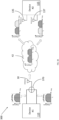
- FIG. 1 is a schematic diagram illustrating a Wi-Fi communication system, which may be operated in accordance with 802.11 (Wi-Fi) modes of operation.
- a first baseband device 10 is in communication with a first RFIC 20, and a first baseband I/O signal 40 can be sent therebetween.
- the first RFIC comprises a first mixer 60.
- the first mixer 60 receives input from a first local oscillator 50.
- the first mixer 60 is in communication with a first antenna 30.
- the first antenna 30 is operable to transmit RF signals 42 to a second antenna 35.
- the first antenna 30 is operable to receive RF signals 42 from the second antenna 35.
- the second antenna 35 is in communication with a second mixer 65.
- a second RFIC 25 comprises the second mixer 65.
- the second mixer 65 receives input from a second local oscillator 55.
- the second RFIC is in communication with a second baseband device 15 and a second baseband I/O signal 45 can be sent therebetween.
- the state-of-the-art 802.11 (Wi-Fi) protocol supports several operation modes whereby a device may transmit/receive information using one or more antenna elements and one of several channel bandwidths (20 MHz, 40 MHz, 80 MHz, 160 MHz) available. Furthermore, the RF transmission may utilise a carrier frequency (f c ) in one of the permitted frequency bands (e.g., 2.4 GHz and 5 GHz) and encode data using a permitted MCS option, for example see http://mcsindex.com.
- f c carrier frequency
- Typical Wi-Fi solutions consist of two key components aside from the antenna(s): a baseband device 10 and an RFIC 20, for example as illustrated in Figure 1 .
- the baseband device/IC generates the modulated baseband signal and/or demodulates the received baseband signal.
- the RFIC is responsible for up/down-converting the baseband signal to/from the RF carrier frequency.
- Devices with 2 or more antenna elements may, for example, support the following features or modes of operation (alongside several others):
- Figure 2 is a schematic diagram illustrating a Wi-Fi communication system operable to transmit and receive multiple streams.
- carrier frequency (f c ) is f and the channel bandwidth is B.
- a first device 110 is connected to a first antenna 130 and a second antenna 132 of the first device.
- the second device 115 is connected to a first antenna 135 of the second device and a second antenna 137 of the second device.
- the first antenna 130 is operable to transmit and receive a first spatial stream 140.
- the first antenna 135 of the second device is also operable to transmit and receive the first spatial stream 140.
- the second antenna 132 of the first device is operable to transmit and receive a second spatial stream 142.
- the second antenna 137 of the second device is also operable to transmit and receive the second spatial stream 142.
- the multitude of transmit and receive antennas may allow (channel conditions permitting) multiple, independent data streams to be communicated simultaneously using the same channel (frequency band) between two MIMO devices. Each independent data stream is then known as a spatial stream.
- Figure 3A is a schematic diagram illustrating a Wi-Fi communication system operable to combine two non-contiguous 80 MHz frequency bands by a single antenna.
- a first device 110 is in communication with a summing amplifier 370 through two channels.
- the summing amplifier 370 is in communication with a first antenna 30.
- the first antenna 30 is operable to provide RF signals 42 to the first antenna 135 that is in communication with second device 115.
- the first antenna 30 is also operable to provide RF signals 42 to the second antenna 137 that is in communication with the second device 115.
- the first antenna 30 is operable to receive RF signals 42 from the first antenna 135 that is in communication with the second device 115.
- the first antenna 30 is also operable to receive RF signals 42 from the second antenna 137 that is in communication with the second device 115.
- the first antenna 135 is operable to receive a first of the non-contiguous 80 MHz frequency bands.
- the second antenna 137 is operable to receive a second of the non-contiguous 80 MHz frequency bands.
- the 80+80 bandwidth mode as illustrated schematically in Figure 3A is a special case of channel bonding whereby two non-contiguous 80 MHz frequency bands are combined for data transmission by a single antenna.
- the first 80 MHz band is received by a first analogue (RF) frontend while the second 80 MHz band is received by a second, different analogue (RF) frontend.
- the first and second frontends receive their respective signals at two different carrier frequencies.
- each ban is transmitted using a different RF frontend with a different carrier frequency (not shown).
- Multiuser-MIMO MU-MIMO
- Figure 3B is a schematic diagram illustrating a Wi-Fi communication system operable to transmit and receive two different spatial streams to two different devices.
- a first device 110 is connected to a first antenna 130.
- the second device 115 is connected to a first antenna 135 and a second antenna 137.
- the first antenna 130 is operable to transmit and receive a first spatial stream 140.
- the first antenna 135 and the second antenna 137 of the second device 115 are also operable to transmit and receive the first spatial stream 140.
- the first device 110 is able to communicate with the second device 115 by the first spatial stream 140.
- the first device 110 is also connected to a second antenna 132.
- the third device 415 is connected to a first antenna 435 and a second antenna 437.
- the second antenna 132 of the first device 110 is operable to transmit and receive a second spatial stream 142.
- the first antenna 435 and the second antenna 437 of the third device 415 are also operable to transmit and receive the second spatial stream 142.
- the first device 110 is able to communicate with the third device 415 by the second spatial stream 142.
- MU-MIMO builds on the basic MIMO concept by allowing each MU-MIMO enabled device to communicate with one or more MU-MIMO enabled remote devices simultaneously using one or more unique spatial streams to each remote device.
- FIG. 5 , 6 , 8 , 9A , 9B , 10A , 10B , 11 , 12 , 14 various signals are illustrated schematically in the figures, in the form of plots of signal magnitude versus frequency.
- the plots generally represent bandwidth and/or centre frequencies of signals representing, for example, data streams and illustrate for example in some embodiments the combining and/or separating of signals or portions of signals by different components of, or present at different points in, systems of embodiments in operation. Shading and/or hatching is used to indicate corresponding data or data streams. In several of the figures arrows are used to indicate the points in the system to which the signals correspond or are present in operation.
- FIG 4A is a schematic block diagram illustrating an optical wireless communication (OWC) link.
- a first OWC apparatus 10 is configured to send a wireless optical signal in which information is encoded.
- the first OWC apparatus 2010 is configured to send the wireless optical signal through a first optical communication channel 2012 to a second OWC apparatus 2016.
- the first optical communication channel 2012 may be a free-space communication channel. Free space communication channels include transmission of optical signals through air, space, vacuum, liquid such as water or similar.
- the first optical communication channel has a first characteristic optical wavelength.
- the second OWC apparatus 2016 is configured to send a further wireless optical signal in which information is encoded.
- the second OWC apparatus 2016 is configured to send the further wireless optical signal through a second optical communication channel 2014 to the first OWC apparatus 2010.
- the second optical communication channel 2014 may be a free-space communication channel.
- the second optical communication channel has a second characteristic optical wavelength, which is different from the first characteristic optical wavelength.
- the first OWC apparatus 10 may be an access point (AP) which comprises a transmitter and a receiver.
- An AP may provide access to a local network.
- An access point may provide data transmission to and/or from a wired network or a Wi-Fi TM or other wireless network and/or other optical wireless communications network, optionally a LiFi network.
- the second OWC apparatus 2016 may be a station (STA) which comprises a transmitter and a receiver.
- STA station
- a station may be portable or fixed. Without limitation, examples of stations include personal computers, laptops, desktops and smart devices, including mobile devices (for example, mobile phones, tablets or digital book readers). Portable stations may be powered by their own battery resource.
- the apparatuses 2010, 2016 may support a bi-directional communication protocol.
- the apparatuses 2010, 2016 may support any suitable communication protocol, for example IEEE 802.15.7, 802.15.13, 802.11 or extensions or developments thereof; ITU-T G.9960 or extensions or developments thereof; or ITU-T G.vlc or extensions or developments thereof.
- Each of the optical communication channels 2012, 2014 may comprise a respective LiFi communication channel.
- a LiFi communication channel may have various desirable characteristics. For example, it may have a range of up to 20 m or more, It has high bandwidth in comparison with for example RF or IrDA (Infrared Data Association) protocols. Full duplex is possible by using two frequencies or frequency ranges allowing high throughput speeds, e.g. halving time or doubling bandwidth of communication. Reception bandwidth is independent of transmission bandwidth, and therefore there may potentially be twice the bandwidth available for the communication exchange. It may be difficult to fake due to complexity of protocol and data stream format. It is possible to spectrum hop, for example.
- the first OWC apparatus 2010 may comprise or form part of a Access Point (AP) device or a luminaire, which may be part of a lighting system.
- the second OWC station (STA) apparatus 2016 may form part of a user device.
- the first optical communication channel 2012 may be a downlink channel that is used to send information from the AP to the STA.
- the second optical communication channel 2014 may be an uplink channel that is used to send information from the STA to the AP.
- the OWC apparatuses 2010, 2016 may each comprise or form part of any suitable device, for example any device configured to transmit and/or receive OWC data.
- FIG. 4B is a schematic diagram of an OWC link in accordance with a related example.
- the OWC link comprises an access point (AP) 2020 and a station (STA) 2030 which are configured for full-duplex communication with each other.
- AP access point
- STA station
- the AP 2020 comprises mixed signal circuitry 2022, an AP transmitter 2024, and an AP receiver 2028.
- the mixed signal circuitry 2022 is configured to receive data from a network (not shown) to which the AP 2020 is connected, and to output a modulation signal that comprises or is representative of the data.
- the AP 2020 is not networked.
- the data may be obtained from any suitable data source or data store.
- the mixed signal circuitry 2022 includes, amongst other components, baseband circuitry, a digital to analogue converter, an analogue to digital converter, an amplification chain, at least one analogue filter, at least one power supply and at least one driver (all not shown), which together can provide desired conditioning of signals.
- baseband circuitry a digital to analogue converter, an analogue to digital converter, an amplification chain, at least one analogue filter, at least one power supply and at least one driver (all not shown), which together can provide desired conditioning of signals.
- a digital to analogue converter an analogue to digital converter
- an amplification chain at least one analogue filter
- at least one power supply and at least one driver all not shown
- the mixed signal circuitry 2022 includes, amongst other components, baseband circuitry, a digital to analogue converter, an analogue to digital converter, an amplification chain, at least one analogue filter, at least one power supply and at least one driver (all not shown), which together can provide
- the AP transmitter 2024 comprises a light source (not shown), which is configured to emit modulated light having a first characteristic wavelength.
- the AP transmitter 2024 further comprises circuitry (not shown) which is configured to drive the first light source to emit light having an intensity that is modulated in accordance with the modulation signal.
- the light source may comprise any suitable light source, for example an LED, a laser, for example a VCSEL (vertical-cavity surface-emitting laser) or a laser diode, or an LEP (light-emitting plasma).
- the light source may comprise a plurality of light sources, for example an array of light sources.
- the AP receiver 2028 comprises at least one photodetector (not shown) which is configured to detect modulated light having a second characteristic wavelength. Any suitable photodetector or photodetectors may be used.
- the AP receiver 2028 may comprise at least one Si PIN photodiode, silicon photomultiplier (SiPM), single photon avalanche diode (SPAD), Graphene-CMOS high-resolution sensor or avalanche photodiode (APD).
- the AP receiver 2028 further comprises receiver circuitry that is configured to obtain a signal from the photodetector that is representative of the light received by the photodetector, and to process the signal from the photodetector to provide a receiver signal to the mixed signal circuitry 2022.
- the mixed signal circuitry 2022 is further configured to receive the receiver signal from the AP receiver 2028 and demodulate the receiver signal to obtain data.
- the mixed signal circuitry 2022 is further configured to send the data to the network (not shown) to which the AP 2020 is connected.
- the STA 2030 comprises mixed signal circuitry 2032, a STA receiver 2034, and a STA transmitter 2036.
- the mixed signal circuitry 2032 comprises baseband circuitry, a digital to analogue converter, an analogue to digital converter, an amplification chain, at least one analogue filter, at least one power supply and at least one driver (all not shown) which together can provide desired conditioning of signals.
- some of the components listed above may be omitted from the mixed signal circuitry 2032 and/or further components not listed may be present such as for example a processor.
- the mixed signal circuitry 2032 may be configured to provide full-duplex communication and/or half-duplex communication.
- the STA receiver 2034 comprises a photodetector (not shown) that is sensitive to light Photodetectors that are sensitive to a broad spectrum of light are known. For example, a photodetector may be sensitive to ultraviolet, visible and infrared wavelengths. In one related example, the STA receiver 2034 comprises at least one APD(avalanche photodiode). In other related examples, the STA receiver 2034 comprises at least one Si PIN photodiode. In further related examples, the STA receiver 2034 may comprise any photodetector that is capable of receiving light of suitable frequencies. For example, the STA receiver 2034 may comprise at least one Graphene-CMOS high-resolution sensor. In further examples, the STA receiver 2034 may comprise at least one silicon photomultiplier (SiPM) or single photon avalanche diode (SPAD) as the photodetector.
- SiPM silicon photomultiplier
- SPAD single photon avalanche diode
- the STA receiver 2034 further comprises circuitry (not shown) which is configured to receive a signal from the photodetector that is representative of modulated light received by the photodetector and to output a receiver signal to the mixed signal circuitry 2032.
- the mixed signal circuitry 2032 is further configured to receive the receiver signal from the STA receiver 2034 and demodulate the receiver signal to obtain data.
- the mixed signal circuitry 2032 includes, amongst other components, an analogue to digital converter (not shown).
- the data received by the STA 2030 may be used in any suitable manner, for example to provide information or a service to a user of a device in which the STA 2030 is incorporated.
- the mixed signal circuitry 2032 is further configured to obtain digital or analogue data for uplink transmission.
- the mixed signal circuitry 2032 may obtain data from an input by a user of a device in which the STA 2030 is incorporated, or from processes running in the device in which the STA 2030 is incorporated.
- the mixed signal circuitry 2032 is configured to output a modulation signal that comprises or is representative of the data.
- the mixed signal circuitry 2032 includes, amongst other components, a digital to analogue converter (not shown).
- the STA transmitter 2036 is used to transmit modulated light.
- the STA transmitter 2036 comprises a light source which is configured to emit modulated light having the second characteristic wavelength. In other related examples, any suitable wavelength or range of wavelengths may be emitted by the STA transmitter 2036.
- the STA transmitter 2036 further comprises circuitry (not shown) which is configured to receive a modulation signal and to drive the light source of the first STA transmitter 2036 to emit light having an intensity that is modulated in accordance with the modulation signal.
- the light source of the STA transmitter 2036 may comprise any suitable light source, for example a laser, for example a VCSEL (vertical-cavity surface-emitting laser) or a laser diode, or an LEP (light-emitting plasma).
- the light source of the STA transmitter 2036 may comprise a plurality of light sources, for example an array of light sources.
- any suitable modulation scheme or schemes may be used for modulation of light by the AP transmitter 2024 and STA transmitter 2036.
- OFDM orthogonal frequency division multiplexing
- modulation schemes may be used, for example on-off keying (OOK), phase shift keying (PSK), M-ary pulse amplitude modulation (M-PAM), M-ary quadrature amplitude modulation (M-QAM), Discrete Hartley transformation, Wavelet packet division multiplexing (WPDM), Hadamard coded modulation (HCM), pulse-position modulation (PPM), Colour shift keying (CSK), carrier-less amplitude and phase (CAP), or discrete multi-tone (DMT).
- OOK on-off keying
- PSK phase shift keying
- M-PAM M-ary pulse amplitude modulation
- M-QAM M-ary quadrature amplitude modulation
- WPDM Wavelet packet division multiplexing
- WPDM Hadamard coded modulation
- PPM pulse-position modulation
- CSK Colour shift keying
- CAP carrier-less amplitude and phase
- DMT discrete multi-tone
- the light may be modulated at a modulation rate between 1
- the modulation scheme or schemes may form part of an OWC communication protocol, such that the optical signal is produced according to the OWC communication protocol.
- the OWC communication protocol may be packet-based.
- the systems of Figures 5 to 17 are described below as including variously mixers, oscillators, baseband devices, amplifiers, antennas, frontends, combiners, filters, phase-locked loops and clocks.
- such components may be implemented as part of, or connected to, the mixed signal circuitry of the systems of Figures 4A or 4B , or where appropriate as part of or connected to the transmitters and/or receivers of those systems.
- such components whether on a transmit side or a receive side, may be considered to comprise or form part of conditioning circuitry.
- the conditioning circuitry may receive signals from, or provide signals to, devices, for example devices 10, 110, 115, 1702, 1720.
- devices for example devices 10, 110, 115, 1702, 1720.
- such devices can be MIMO devices, for example MIMO baseband devices.
- the MIMO devices can comprise MIMO devices intended for use with radio-frequency (RF) transmission circuitry.
- the MIMO devices can comprise devices operating in accordance with the 802.11 standard.
- the MIMO devices can comprise a MIMO baseband device and an RF integrated circuit.
- Two methods for generating a baseband signal suitable for OWC from existing Wi-Fi or similar wireless communication systems are as follows.
- Figure 5 is a schematic diagram illustrating a system to receive an in-phase signal and a quadrature signal from a baseband device and output an intermediate frequency signal.
- the in-phase signal is received by a first mixer 560.
- the quadrature signal is received by a second mixer 562.
- the first mixer 560 receives an input from a local oscillator 550 with a 0 degree phase offset.
- the second mixer 562 receives an input from the local oscillator 550 with a 90 degree phase offset.
- the first mixer 560 and the second mixer 562 output signals that are received by a summing amplifier 570.
- the summing amplifier 570 outputs a low intermediate frequency/baseband signal.
- the mixers 560, 562 and amplifier make up or form part of conditioning circuitry.
- the in-phase and quadrature (I/O) signals from the baseband device are directly accessible, it is possible to utilise a low frequency local oscillator (e.g. B/2 + ⁇ where B is the signal bandwidth and ⁇ is a small guard band) to directly modulate the baseband signal to low IF. This must be done to shift the double-sided signal spectrum to positive-only frequencies that can be transmitted/received by the OWC frontend.
- a low frequency local oscillator e.g. B/2 + ⁇ where B is the signal bandwidth and ⁇ is a small guard band
- Figure 6 is a schematic diagram illustrating a system that receives the RF output from the RFIC, down-converts this signal, and output the down-converted signal.
- the RF signal is received by a mixer 660, forming part of conditioning circuitry.
- the mixer 660 also receives input from a local oscillator 650.
- the mixer 660 outputs the intermediate frequency/baseband signal.
- Figure 7 is a schematic diagram illustrating a MIMO transmission system that comprises multiple antennas on the transmitter and receiver sides.
- the first antenna 730 is operable to communicate with the fourth antenna 735, fifth antenna 737, and sixth antenna 739.
- the second antenna 732 is operable to communicate with the fourth antenna 735, fifth antenna 737, and sixth antenna 739.
- the third antenna 736 is operable to communicate with the fourth antenna 735, fifth antenna 737, and sixth antenna 739.
- MIMO transmission systems in relation to wireless communication generally relates to multiple antennas on transmitter and receiver sides.
- MIMO can be sub-divided into three main categories: precoding, spatial multiplexing and diversity coding (defined at the start of this document). While aspects of all categories are discussed below, various embodiments generally relate to the use of spatial multiplexing.
- precoding precoding
- spatial multiplexing spatial multiplexing
- diversity coding defined at the start of this document. While aspects of all categories are discussed below, various embodiments generally relate to the use of spatial multiplexing.
- OFDM orthogonal frequency-division multiplexing
- the received signal can be represented as a vector y .
- y H s + n where n is the noise.
- this is the sum of ambient shot light noise and thermal noise and is independent of the transmitted signals and main noise impairment assumed in OWC.
- the signal emitted by transmitter N t is given by s N t etc.
- H is the N t ⁇ N r channel matrix below where h n r n t represents the transfer factor of the wireless link between transmitter n t and receiver n r .
- H h 11 ⁇ h 1 N t ⁇ ⁇ ⁇ h N r 1 ⁇ h N r N t
- the channel can be retrieved.
- the matrix H is singular if using typical OWC TXs and RXs in a MIMO configuration to transmit the same information.
- a receiver cannot tell which transmitter a signal comes from because they all look the same or very similar. Therefore, it is typically very difficult to realise MIMO gains from a wireless communication system where the RF antennas have been replaced with single wavelength (colour) optical transceivers in a straight-forward, one-for-one basis.
- colour single wavelength
- WDM wavelength division multiplexing
- each wavelength is independent, the transmissions remain orthogonal to each other (even though they may share the same space and spectrum at the same time).
- the channel matrix H remains invertible (due to the orthogonality of the wavelengths), allowing the MIMO algorithms to function correctly and therefore the multiplexing gain is realised.
- the main drawback of this approach is the number of different wavelengths and transceivers (e.g. comprising or associated with frontends and/or frontend circuitry) required which can be challenging from both a cost and optical wavelength separation (emitter bandwidth and filter response) perspective.
- Another solution is the use of different optical polarisation but the same drawbacks as WDM apply.
- the present document describes a number of arrangements that allow the MIMO multiplexing gains to be realised (invertible H matrix) while reducing the complexity and cost of a high performance OWC system, which may be implemented using existing, commercially available MIMO capable baseband devices.
- the baseband devices may be 802.11 baseband devices designed for use in RF communication such as Wi-Fi. This is achieved, for example, using MIMO enabled 802.11 Wi-Fi chips/chipsets, specifically repurposing the Wi-Fi chips for use in OWC.
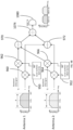
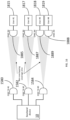
- Figure 8 is a schematic diagram illustrating an OWC communication system operable for spatial stream combining.
- f1 f2
- f1 and f2 are the frequencies or frequency ranges used for each of the spatial streams respectively.
- the same circuit can be applied to channel aggregation systems as well to optimize the inter-channel spacing (e.g. when the two channels are far apart: f2-f1 >> B).
- the first device 110 is in communication with conditioning circuitry that includes a first RF downconversion local oscillator (LO) 850 and provides a first frontend stream with frequency range centred at frequency f1 to LO 850.
- the first device 110 is in communication with a second RF downconversion LO 852 included in the conditioning circuitry and that provides a second frontend stream with frequency range centred at frequency f2 to LO 852.
- Outputs from the first RF downconversion LO 850 and the second RF downconversion LO 852 are provided as inputs to a combiner in the form of summing amplifier 870 that is included in the conditioning circuitry.
- the output of the summing amplifier 870 is an input for an OWC transmitter 880.
- the OWC transmitter 880 is operable to transmit one or more streams to an OWC receiver 885 using modulated light transmission in accordance with OWC techniques.
- the OWC receiver 885 is in communication with a first RF upconversion LO 855 and a second RF upconversion LO 857.
- the second device 115 is in communication with the first RF upconversion LO 855 and a second RF upconversion LO 857.
- the multiple spatial streams generated by a MIMO enabled baseband device can be down-converted and combined to yield a single baseband signal that can be subsequently transmitted by at least one transmitter in a first single wide band OWC transceiver and received by a single receiver or receiver array in a second wide band OWC transceiver.
- the combining, at the transmit side, and subsequent separating, at the receive side, of the data streams is illustrated schematically in Figure 8 by the magnitude versus signal plots included in the figure. It can be seen that there is a separation by a guard band between the two parts of the combined signal.
- the concept is scalable and can be extended to support any number of channels (e.g ., N) as long as the OWC transceiver can support a signal bandwidth of at least N ⁇ (B + ⁇ ), where B is the bandwidth of each stream and ⁇ is a small guard band between each of the signal bands.
- ⁇ should be an integer multiple of the subcarrier spacing to maintain optimal orthogonality between each signal band/segment.
- the combiner in Figure 8 and subsequent figures may be any system or circuitry that allows two or more electrical signals to be added together - e.g., a summing amplifier or a resistive combiner.
- Summing amplifiers in embodiments may be replaced with resistive combiners or any other suitable combiner in alternative embodiments.
- the RF up conversion may be a direct conversion to RF or include a conversion to an intermediate frequency (IF).
- IF intermediate frequency
- the undesired image frequencies may be optionally filtered out at IF or RF.
- the same technique is equally applicable to systems where direct modulation to IF is possible (for example as illustrated in Figure 5 ) - e.g. a system that is capable of quadrature modulating the I/O output directly to the OWC baseband signal.
- the I/O output of the first antenna may be quadrature modulated to the first sub-band (e.g., B/2 + ⁇ ), the I/O output of the second antenna may be quadrature modulated to the second sub-band (e.g., 3B/2 + 2 ⁇ ), etc..
- spatial stream combining may be implemented for I and Q signals independently and transmitted/received using independent OWC frontends as shown schematically in Figure 9 .
- Figure 9A is a schematic diagram illustrating a system that obtains an in-phase signals and quadrature signals from a baseband-enabled device and processes them for transmission by a first antenna 980 and second antenna 982.
- an in-phase signal is received by a first mixer 960 as an input.
- a quadrature signal is received by a second mixer 962 as an input.
- the first mixer 960 and the second mixer 962 also receive input from a first local oscillator 950.
- An in-phase signal is received by a third mixer 964 as an input.
- a quadrature signal is received by a fourth mixer 966 as an input.
- the first mixer 960 and the second mixer 962 also receive input from a second local oscillator 952.
- a first summing amplifier 970 receives input from the second mixer 962 and the fourth mixer 966.
- the first OWC transmitter 980 receives input from the first summing amplifier 970.
- the first OWC transmitter 980 is operable to transmit the OWC quadrature signals.
- a second summing amplifier 972 receives input from the first mixer 960 and the third mixer 964.
- the second OWC transmitter 982 receives input from the second summing amplifier 972.
- the second OWC transmitter 982 is operable to transmit the OWC in-phase signals.
- the components illustrated in Figure 9A apart from the transmitters, make up or form part of conditioning circuitry.
- FIG. 9A An alternative to the embodiment of Figure 9A is to combine the I and Q signals independently and then add them in quadrature as shown in Figure 9B .
- This approach is technically similar to the approach of quadrature modulating each stream to low IF/baseband and then combining prior to transmission over an OWC frontend (as shown in Figure 5 ).
- the embodiment of Figure 9B is similar to the embodiment of Figure 9A but a further summing amplifier is provided, which receives and sums inputs from the summing amplifiers 970, 972 combines those inputs and provides an output to single OWC transmitter 1080 rather than the pair of OWC transmitters 980, 982 of the embodiment of Figure 9A .
- Stream 1 may be down-converted from f 1 to 1 ⁇ 2 B + ⁇ while stream 2 may be down-converted to 3 2 B + 2 ⁇ .
- the difference in frequency shift would be B + ⁇ .
- the digital baseband would receive stream 1 with a carrier offset of f off while it would receive stream 2 with a carrier offset of f off + ( B + ⁇ ) ⁇ osc , where ⁇ osc is the frequency error of the local oscillator at the transmitter.
- One solution may be to use a high precision oscillator, for example with a frequency error below 0.1 ppm.
- a high precision oscillator for example with a frequency error below 0.1 ppm.
- oscillators are expensive.
- a second solution is to implement a receiver that estimates the frequency offset of each MIMO stream and applies the required correction to each local oscillator of the RF up-conversion circuits.
- a receiver is still be relatively complex as it needs to have multiple inputs (for each multiplexed stream) and the necessary frequency offset estimation circuitry.
- a third solution may be to recover the transmitter clock at the receiver.
- the reference clock is used to generate the local oscillator (LO) signal by means of a synthesiser.
- the synthesiser may have a fixed ratio, or it may be programmable (e.g., a fractional/integer-n synthesiser/PLL).
- a pilot signal may be added to the transmitted signal.
- the pilot may be an attenuated or amplified version of the reference clock, or it may be another signal having a fixed relationship (e.g., a fixed ratio) with the reference clock.
- the pilot signal may be added by attenuating a reference clock signal with an attenuator.
- a bandpass filter may be used to extract the received pilot from the received signal and a phase-locked loop (PLL) may lock to the pilot, recovering the reference clock signal.
- PLL phase-locked loop
- the recovered reference clock signal is then used to derive the local oscillator frequencies for the upconverting mixers - eliminating any frequency offset between the streams.
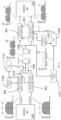
- the system of Figure 10A provides spatial stream combining with a pilot signal extracted on the receiver side using a bandpass filter and PLL with a VCO lock when no pilot signal is present.
- the first device 110 is in communication with a first RF downconversion local oscillator (LO) 850.
- the first device 110 is also in communication with a second RF downconversion LO 852.
- the first RF downconversion LO 850 and the second RF downconversion LO 852 are inputs for a summing amplifier 1170.
- a reference clock 1120 is operable to provide a reference signal as an input to the first RF downconversion LO 850 and the second RF downconversion LO 852.
- a gain component 1122 is operable to receive the reference signal from the reference clock 1120 and output a pilot signal.
- the summing amplifier 1170 receives an input from the gain component 1122.
- the output of the summing amplifier 1170 is an input for an OWC transmitter 1180.
- the OWC transmitter 1180 is operable to transmit one or more streams to an OWC receiver 1185.
- the OWC receiver 1185 is in communication with a bandpass filter 1125, a first RF upconversion LO 855, and a second RF upconversion LO 857.
- the bandpass filter 1125, first RF upconversion LO 855 and the second RF upconversion LO 857 receive input from the OWC receiver 1185.
- the bandpass filter 1125 outputs a signal to a phase-locked loop (PLL).
- the output of the PLL is an input for the first RF upconversion LO 855.
- the second device 115 is in communication with the first RF upconversion LO 855 and a second RF upconversion LO 857.
- the components illustrated in Figure 10A , other than transmitters and receiver, and devices 110, 115 may be considered to make up or form part of conditioning circuitry.
- the embodiments of Figure 10A can provide spatial stream combining with a pilot extracted on the receiver side using a bandpass filter and PLL.
- the optical transmitter (optionally an LED, laser or light emitting plasma) only when a packet is transmitted.
- the pilot may not be present at the receiver side all the time, and the recovery of the reference clock may be more complicated.
- Figure 10B One possible option according to embodiments is shown in Figure 10B , which is similar to the embodiment of Figure 10A and in which the voltage-controlled oscillator (VCO) 1227 of the PLL may be locked when no input is present.
- VCO voltage-controlled oscillator
- the PLL loop bandwidth and the packet spacing the drift of the frequency during off time of the transmitter may be acceptable, e.g. no more than a few Hz.
- the embodiment of Figure 10B can provide spatial stream combining with a pilot signal extracted on the receiver side using a bandpass filter and PLL with a VCO lock when no pilot signal is present.
- the OWC transmitter of Device 1 can be switched when a signal is ready for transmission by using an envelope detector and comparator.
- FIG. 11 is a schematic illustration of a further embodiment.
- a microcontroller unit MCU
- the correction algorithms can be designed to operate with both continuous and intermittent pilot signals (e.g., by updating the estimator only when a pilot is received). This is different from the previous solutions where the recovered reference clock is utilised directly.
- a microcontroller (MCU) at the receiver is used to implement frequency offset estimation and correction.
- the embodiment of Figure 11 is similar to that of Figures 10A and 10B , and like reference numerals are used to refer to like features, but the embodiment of Figure 11 includes MCU 1329 and additional bandpass filter 1125 and local reference clock 1321 components on the receive side.
- the MCU 1329 can be used to estimate a frequency difference between the pilot signal and the local oscillator(s) and correct it, as indicated schematically by the dashed lines in Figure 11 .
- the embodiment of Figure 11 can provide spatial stream combining with a pilot signal extracted on the receiver side using an MCU to estimate the frequency difference between the pilot signal and a digitally controlled oscillator and correct it.
- a microcontroller unit can also be provided in variants of any of the embodiments described and/or illustrated herein, if it is desired to provide control functions using such MCU. Any other suitable controller can be provided in other embodiments.
- Figures 9 to 11 are applicable to systems where direct modulation to IF is possible (for example, in similar manner to Figure 5 ).
- Transmitting the pilot at the same time as the data signal can reduce the dynamic range available to the data signal and this may reduce the performance of the system.
- the pilot and data signal may be transmitted at mutually exclusive time periods in some embodiments.
- the pilot may be transmitted as an intermittent burst or continuously during periods of no data signal transmission.
- Another solution according to some embodiments is to transmit the pilot over an alternative medium such as via a separate RF communication channel.
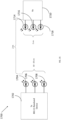
- Some baseband devices may support a form of channel aggregation where independent data signals with different carrier frequencies are transmitted from each of the frontends.
- One example of such a system may be a Wi-Fi baseband device operating in the 80+80 channel bandwidth mode where the first 80 MHz signal may be modulated with a first carrier frequency (e.g., channel 42: 5.21 GHz) while the second 80 MHz signal is modulated with a second, different carrier frequency (e.g ., channel 58: 5.29 GHz).
- signals from device 110 are provided to a summing amplifier 1170 then provide to a single mixer 1460, which also receives a signal from local oscillator 1450, and provided a combined signal to transmitter 1180 for transmission as a modulated light signal according to OWC techniques.
- the signals are separated out and provided to device 115 using mixer 1465 and local oscillator 1455 .
- the embodiment of Figure 12 can provide channel aggregation for OWC.
- Each frontend operates at the same bandwidth but at different RF carrier frequency.
- a single mixer down-converts the combined signal to baseband for OWC.
- the streams may be divided into multiple groups and the stream combining technique applied to each of the groups separately such that the combined bandwidth for each group is within the bandwidth limitation of the OWC transceiver.
- the combined signal from each group may then be communicated over OWC transceivers operating at different, non-overlapping wavelengths as illustrated schematically in Figure 13 , which shows a further embodiment.
- Respective combined signals are provided to transceivers 1580, 1582, 1584, which transmit them as modulated light signals in accordance with OWC techniques.
- the combined signals are received by transceivers 1585, 1587 and 1589 and the combined signals are separated out and provided to second device 115.
- the stream combining concept may also be used to aggregate multiple wireless communication signals (potentially originating from different digital basebands within a single device such as a handset) into a single wideband signal capable of being transmitted and received using a single OWC transceiver 1180, 1185 as illustrated schematically in Figure 14 in accordance with an embodiment.
- the multiple wireless signals may be of the same (e.g., MIMO WiFi as described above) or different (e.g., LTE, Bluetooth, WiFi, ultrawide band, Wi-Gig, cellular or mm wave) communication protocols.
- the devices 110, 115 include respective digital baseband circuitry for each of the communication protocols.
- Down/up conversion components 1650, 1652, 1653, 1654 and amplifier or mixer 1670 on the transmit side, and up/down conversion components 1655, 1657, 1658, 1659 and filters 1645, 1647, 1648, 1649, are provided to process and combine the signals on the transmit side, and to process and separate the signals on the receive side.
- the embodiment of Figure 14 includes transceivers 1180, 1185 for transmitting the signals as modulated light signals in accordance with OWC techniques.
- the frequency up/down-conversion method allows the signals to be positioned much closer together - improving bandwidth efficiency.
- each of the signals may be filtered by the filters 1645, 1647, 1648, 1649 for improved performance before being fed into the relevant digital baseband(s) components.
- the signals may be RF, IF, or an I/O baseband.
- the digital baseband MIMO device in device 101 may, for example, be replaced with a non-MIMO device such that the three (or any other suitable number) of devices (e.g. individual digital baseband circuitries) included in device 101 together provided multiple inputs and multiple outputs with each individual one of those devices (e.g. individual digital baseband circuitries) having, for example, a single input and/or single output.
- devices e.g. individual digital baseband circuitries
- the digital baseband MIMO device in device 101 may, for example, be replaced with a non-MIMO device such that the three (or any other suitable number) of devices (e.g. individual digital baseband circuitries) included in device 101 together provided multiple inputs and multiple outputs with each individual one of those devices (e.g. individual digital baseband circuitries) having, for example, a single input and/or single output.
- An 802.11 chip operating in 2x2 MIMO mode using STBC and enabled for both Wi-Fi and LiFi can provide redundancy and robustness.
- a first stream is connected to an RF front end, the second stream to the optical front end.
- Each stream contains the full information being transferred. Therefore, if Wi-Fi drops out, data can go over the optical path. If LiFi drops out, data can go over the RF path. If Wi-Fi and LiFi are present, robustness and throughput are improved.
- This idea avoids switching between different front ends and allows a smooth handover from LiFi to Wi-Fi and reverse in case one of them fades away.
- the system can also be used for sending different data to different users over different subsets of the channels based on user capabilities (what they can receive and transmit), signal strength or level of security of the user and/or data. For example, more secure data can be sent via LiFi while less secure data can be sent via Wi-Fi to the same or different users.
- a single 802.11 baseband device with MIMO functionality can also be used to drive multiple, spatially separate/remote optical front ends (OFEs) with either the same or different data across the same (signal) frequency and wavelength, as illustrated schematically in Figure 15 .
- OFEs optical front ends
- Different gain on each channel will allow the channels to be distinguished.
- a non-singular channel matrix H will be produced.
- the gain at a given receiver Rx based on the geometry of the system h can be estimated in relation to the angle of emergence with respect to the transmitter Tx i ⁇ , the angle of incidence with respect to the receiver Rx j ⁇ and the distance between Tx i and Rx i d .
- h ⁇ k + 1 A 2 ⁇ d 2 cos k ⁇ cos ⁇ 0 ⁇ ⁇ ⁇ 1 / 2 0 ⁇ > ⁇ 1 / 2
- A is the detector area.
- Figure 15 shows a configuration of a baseband device 1702 with multiple outputs, transmitted using transmitter LEDs 1704, 1706, 1708 and received by receivers 1714, 1716, 1718 of a system 1700 according to an embodiment.
- the receiver signals from the receivers 1714, 1716, 1718 are provided to a receiver device 1720 for subsequent processing.
- the proximity of the output transmitters 1704, 1706, 1708 may provide for almost complete overlap in coverage area and hence the gain across the channels are very similar. In this case, each individual channel cannot be distinguished.
- the MIMO channels may be spatially separated such that each channel covers a non-overlapping area of space as shown in Figure 16 , which is a schematic illustration of a further embodiment, in which transceivers 1580, 1582, 1584 are connected too baseband device 10 and provide coverage areas, for example, at least some of which are non-overlapping and that are used to communicate with respective transceivers 1885, 1887, 1889, 1888 of users 1815, 1817, 1818, 1819.
- MU-MIMO functionality this allows a single baseband device to serve multiple users simultaneously across a much larger space which may be beneficial from a cost perspective. If MU-MIMO is unavailable, the users in each area will be served in turn instead in a TDMA fashion.
- a variation of this concept is where a number of the MIMO channels/streams are connected to OWC frontends while the others may be connected to a standard RF antenna.
- Such as system would allow a single baseband device to serve both OWC and RF users simultaneously with independent data streams (unlike the previous concept where redundancy is achieved by transmitting the same data over OWC and RF ).
- An ideal communication channel is flat. However, in reality the channel is not flat. This is because of factors such as interference and fading with signal strength and SNR varying across the full width of the channel.
- the performance of a system can be improved by applying bit and power loading unevenly across multiple narrow bandwidth subchannels which together comprise the entire communication channel, effectively weighting the signal received at different narrow subchannels based on the known or estimated SNR and known or estimated attenuation of a given subchannel.
- Figure 27 shows a) ideal channel performance b) real-world channel performance due to factors such as interference and fading c) bit and power loading across narrow bandwidth subchannels to compensate for variation in performance across full bandwidth.
- Wi-Fi typically does not support power loading. In Wi-Fi, coding and modulation scheme are also fixed across the whole channel. This does not provide optimal use of modulation schemes across the channel bandwidth.
- spatial stream combining presents a mechanism for emulating bit and power loading as each individual spatial stream can be considered as a single narrowband subchannel.
- Multiple spatial streams can therefore be aggregated using concepts or techniques described in accordance with embodiments to yield the complete communication bandwidth where bit and power loading has been effectively applied across different segments of that communication bandwidth.
- independent modulation and coding schemes MCS
- power loading can be used for narrow bandwidth subchannels across the whole bandwidth to emulate bit and power loading. Aggregation can then combine the narrowbands into one spectrum. Different power loading will distinguish between the different channel gains (i.e. power loading), and the MCS chosen can be adapted to a given narrow subchannel based on its characteristics. For example, if a subchannel is weak, with low SNR, use an appropriate scheme that may support a more robust communication link (e.g. 4QAM rather than 64QAM).
- Some level of automatic adaptation selection of appropriate MCS for each narrowband subchannel is inherently built into the protocol as the baseband device already uses training and feedback to determine the correct MCS for each spatial stream. The same training information can also be used to subsequently apply power loading to each spatial stream.
- This concept can also be used to serve multiple users via different narrowband subchannels.
- an OWC system Alternatively or additionally there may be provided an OWC system:
- 802.11 chips may be used by any or all of the OWC systems.
Landscapes
- Engineering & Computer Science (AREA)
- Computer Networks & Wireless Communication (AREA)
- Signal Processing (AREA)
- Physics & Mathematics (AREA)
- Electromagnetism (AREA)
- Computing Systems (AREA)
- Optical Communication System (AREA)
- Radio Transmission System (AREA)
Claims (15)
- Optisches drahtloses Kommunikationssystem (OWC-System), das Folgendes umfasst:eine Multiple-input-multiple-output- (MIMO-) Vorrichtung (110, 115, 1702, 1720), die eine Basisbandvorrichtung umfasst, die konfiguriert ist, um modulierte Basisbandsignale zu generieren, wobei die MIMO-Vorrichtung konfiguriert ist, um eine Vielzahl von MIMO-Vorrichtungs-Ausgangssignalen bereitzustellen, wobei die Vielzahl von MIMO-Vorrichtungs-Ausgangssignalen elektrische Signale mit MIMO-Vorrichtungs-Ausgangssignalfrequenzen umfasst, wobei die MIMO-Vorrichtungs-Ausgangssignalfrequenzen Basisband- oder RF- oder Zwischenfrequenzen umfassen und wobei jedes MIMO-Vorrichtungs-Ausgangssignal einen jeweiligen Datenstrom einer Vielzahl von Datenströmen darstellt;eine Konditionierungsschaltung, die eine elektrische Schaltung umfasst, die konfiguriert ist, um die Vielzahl von MIMO-Vorrichtungs-Ausgangssignalen, die von der MIMO-Vorrichtung ausgegeben werden, zu empfangen und um mindestens ein Frequenz-Aufwärtswandlungsverfahren oder Frequenz-Abwärtswandlungsverfahren mit einem oder mehreren der Vielzahl von MIMO-Vorrichtungs-Ausgangssignalen im elektrischen Bereich durchzuführen, um eine Vielzahl von aufwärts- oder abwärtsgewandelten Signalen zu erzeugen, wobei die Konditionierungsschaltung einen Kombinierer (870, 970, 972, 1170) umfasst, der konfiguriert ist, um die konvertierten Signale zu kombinieren, um mindestens ein konditioniertes Signal zu erzeugen, das repräsentativ für die Datenströme ist und sich für die Übertragung unter Verwendung einer OWC-Sendevorrichtung eignet.eine OWC-Sendevorrichtung, die mindestens einen Sender (880, 980, 982, 1080, 1180) zum Übertragen von Licht umfasst und der so konfiguriert ist, um auf das mindestens eine konditionierte Signal zu reagieren, um Licht zu übertragen, das repräsentativ für die Datenströme ist, die mindestens einen Sender verwenden,wobei die Vielzahl von Datenströmen mindestens einen ersten Datenstrom und einen zweiten Datenstrom umfasst und wobei das mindestens eine von der Konditionierungsschaltung erzeugte konditionierte Signal Folgendes umfasst:
ein konditioniertes Signal, das einen ersten Teil, der eine erste OWC-Frequenz oder einen ersten Bereich von OWC-Frequenzen aufweist, und mindestens einen zweiten Teil, der eine zweite OWC-Frequenz oder einen zweiten Bereich von OWC-Frequenzen aufweist, einschließt, wobei der erste Teil den ersten Datenstrom und der zweite Teil den zweiten Datenstrom darstellt. - System nach Anspruch 1, wobei der Datenstrom/die Datenströme eine Vielzahl von verschiedenen räumlichen Strömen umfasst/umfassen, die für die Übertragung mit Antennen oder anderen Sendern in verschiedenen räumlichen Positionen vorgesehen oder geeignet sind.
- System nach Anspruch 1 oder 2, wobei:die MIMO-Vorrichtung eine MIMO-Vorrichtung umfasst, die für die Verwendung mit einer Radiofrequenz (RF)-Übertragungsschaltung vorgesehen ist; und/oderdie MIMO-Vorrichtung eine Vorrichtung umfasst, die gemäß dem 802.11-Standard betrieben wird; und/oderdie MIMO-Vorrichtung eine MIMO-Basisbandvorrichtung und eine integrierte RF-Schaltung umfasst.
- System nach einem der vorhergehenden Ansprüche, wobei das mindestens eine konditionierte Signal mindestens ein Basisbandsignal und/oder mindestens eine Zwischenfrequenz zwischen Basisband und RF umfasst.
- System nach einem der vorhergehenden Ansprüche, wobei der mindestens eine Sender zum Übertragen von Licht einen einzigen Sender zum Übertragen von Licht umfasst und/oder wobei das OWC-System ferner eine RF-Sendevorrichtung umfasst, die mindestens eine RF-Antenne umfasst.
- System nach Anspruch 1, wobei der erste Bereich von OWC-Frequenzen und der mindestens zweite Bereich von OWC-Frequenzen nicht überlappen, wobei optional der erste Bereich von OWC-Frequenzen und der mindestens zweite Bereich von OWC-Frequenzen durch einen weiteren Bereich von OWC-Frequenzen, optional ein Schutzband, voneinander getrennt sind.
- System nach Anspruch 6, wobei mindestens eines von a) und b) gilt:a) der erste Bereich von OWC-Frequenzen und/oder der mindestens zweite Bereich von OWC-Frequenzen Unterträger einschließen, die durch einen Frequenzabstand voneinander getrennt sind, und das Schutzband eine Breite hat, die im Wesentlichen einem ganzzahligen Vielfachen des genannten Unterträgerabstands entspricht;b) jede des ersten Bereichs von OWC-Frequenzen und des zweiten Bereichs von OWC-Frequenzen einen jeweiligen Unterkanal innerhalb der nutzbaren OWC-Bandbreite der OWC-Sendevorrichtung darstellt oder umfasst.
- System nach einem der vorhergehenden Ansprüche, wobei die MIMO-Vorrichtung so beschaffen ist, dass mindestens eins oder mehrere der Vielzahl von MIMO-Vorrichtungs-Ausgangssignalen, die von der MIMO-Vorrichtung ausgegeben werden, eine(n) Frequenz oder Frequenzbereich nutzt/nutzen, die/der sich von der/dem der OWC-Sendevorrichtung unterscheidet/unterscheiden, optionalwobei die MIMO-Vorrichtung eine oder mehrere Frequenz(en) verwendet, die höher sind als die gewünschte(n) OWC-Frequenz(en) und die Konditionierungsschaltung konfiguriert ist, um ein Abwärtswandlungsverfahren durchzuführen; und/oderdie MIMO-Vorrichtung eine oder mehrere Frequenz(en) verwendet, die niedriger sind als die gewünschte(n) OWC-Frequenz(en) und die Konditionierungsschaltung konfiguriert ist, um ein Aufwärtswandlungsverfahren durchzuführen.
- System nach einem der vorhergehenden Ansprüche, wobei die Konditionierungsschaltung konfiguriert ist, um ein Taktsignal oder ein anderes Zeitsignal zum mindestens einem konditionierten Signal hinzuzufügen oder mit diesem zu verbinden, wobei das Taktsignal oder andere Zeitsignal optional in einem Pilotsignal eingeschlossen oder mit diesem verbunden ist.
- System nach einem der vorhergehenden Ansprüche, wobei die Vielzahl von MIMO-Vorrichtungs-Ausgangssignalen, die von der MIMO-Vorrichtung ausgegeben werden, mindestens ein erstes Signal und ein zweites Signal umfassen, wobei das erste Signal und das zweite Signal jeweils seinen jeweiligen Datenstrom darstellt unter Verwendung im Wesentlichen derselben Frequenz oder desselben Frequenzbereichs, optional, wobei die Konditionierungsschaltung konfiguriert ist, um jedes der ersten und zweiten Signale auf Basisband oder Zwischenfrequenz(en) zu verschieben und um das erste Signal unter Verwendung eines ersten Bereichs von OWC-Frequenzen darzustellen und das mindestens eine zweite Signal unter Verwendung von mindestens eines zweiten, unterschiedlichen Bereichs von OWC-Frequenzen darzustellen.
- System nach einem der Ansprüche 1 bis 10, wobei die Vielzahl von MIMO-Vorrichtungs-Ausgangssignalen, die von der MIMO-Vorrichtung ausgegeben werden, mindestens ein erstes Signal und ein zweites Signal umfasst, wobei das erste Signal und das zweite Signal jeweils seinen jeweiligen Datenstrom darstellt unter Verwendung einer verschiedenen MIMO-Vorrichtungsfrequenz oder eines verschiedenen Bereichs von MIMO-Vorrichtungsfrequenzen, wobei optional das erste Signal und das zweite Signal verschiedene Trägerfrequenzen aufweisen, wodurch eine Kanaltrennung zwischen dem ersten Signal und dem zweiten Signal, die von der MIMO-Vorrichtung ausgegeben werden, bereitgestellt wird, wobei ferner optional die Konditionierungsschaltung konfiguriert ist, um eine Abwärtswandlung der ersten und zweiten Signale auf Basisband oder Zwischenfrequenz(en) bereitzustellen, die im Wesentlichen die Kanaltrennung des ersten Signals und des zweiten Signals im daraus resultierenden konditionierten Basisband- oder Zwischenfrequenz-Signal aufrechterhält.
- System nach einem der vorhergehenden Ansprüche, wobei die Konditionierungsschaltung angeordnet oder konfiguriert ist, um die Vielzahl von MIMO-Vorrichtungs-Ausgangssignalen der MIMO-Vorrichtung in eine Vielzahl von OWC-Gruppen aufzuteilen und um ein jeweiliges Konditionierungsverfahren für jede der Gruppen durchzuführen, wobei jede OWC-Gruppe optional ein einziges der konditionierten Signale umfasst oder jede OWC-Gruppe eine jeweilige Vielzahl von den Signalen der MIMO-Vorrichtung umfasst.
- System nach einem der vorhergehenden Ansprüche, wobei der mindestens eine Sender der OWC-Sendevorrichtung eine Vielzahl der Sender umfasst und die Konditionierungsschaltung konfiguriert ist, um für jeden der Sender ein jeweils verschiedenes der konditionierten Signale bereitzustellen, sodass ein Datenstrom/Datenströme der verschiedenen konditionierten Signale von verschiedenen der Sender übertragen werden, wobei optional mindestens einer der Vielzahl von Sendern konfiguriert sein kann, um Licht verschiedener Wellenlänge(n) an mindestens einen anderen der Sender zu übertragen.
- System nach einem der vorhergehenden Ansprüche, das ferner Folgendes umfasst:eine OWC-Empfangsvorrichtung, die mindestens einen Empfänger (885, 1185) zum Empfangen von Licht und zum Generieren von mindestens einem empfangenen OWC-Signal vom empfangenen Licht umfasst, das eine Vielzahl von Datenströmen darstellt;eine Konditionierungsschaltung, die konfiguriert ist, um mindestens ein OWC-Signal zu empfangen, das den Datenstrom/die Datenströme der OWC-Empfangsvorrichtung darstellt, und um das mindestens eine empfangene OWC-Signal zu verarbeiten, wodurch eine Vielzahl von konditionierten Signalen zu erzeugen, um diese als Eingangssignale an eine Multiple-in-multiple-out- (MIMO-) Vorrichtung (110, 115, 1702, 1720) bereitzustellen, die eine Basisbandvorrichtung umfasst, die konfiguriert ist, um Basisbandsignale zu demodulieren, wobeidie MIMO-Vorrichtung konfiguriert ist, um die Vielzahl von konditionierten Signalen zu empfangen, die jeweils einen jeweiligen Datenstrom der Vielzahl von Datenströmen darstellenwobei die Vielzahl von Datenströmen mindestens einen ersten Datenstrom und einen zweiten Datenstrom umfassen und das mindestens eine von der Konditionierungsschaltung erzeugte konditionierte Signal ein konditioniertes Signal umfasst, das einen ersten Teil, der eine erste OWC-Frequenz oder einen ersten Bereich von OWC-Frequenzen aufweist, und mindestens einen zweiten Teil, der mindestens eine zweite OWC-Frequenz oder einen zweiten Bereich von OWC-Frequenzen aufweist, einschließt, wobei der erste Teil den ersten Datenstrom und der zweite Teil den zweiten Datenstrom darstellt undwobei die Konditionierungsschaltung eine elektrische Schaltung umfasst, die konfiguriert ist, um mindestens ein Frequenz-Aufwärtswandlungsverfahren oder Frequenz-Abwärtswandlungsverfahren im elektrischen Bereich durchzuführen, um von dem mindestens einen empfangenen OWC-Signal die Vielzahl von konditionierten Signalen zu erzeugen, die eine gewünschte Frequenz oder einen gewünschten Bereich von Frequenzen innerhalb eines Bereichs von Frequenzen aufweisen, die von den Eingangssignalen zur MIMO-Vorrichtung verwendet werden, wobei der Bereich von Frequenzen, die von den Eingangssignalen zur MIMO-Vorrichtung verwendet werden, RF- oder Zwischenfrequenzen oder Basisbandfrequenzen umfassen.
- Optisches drahtloses Kommunikationsverfahren (OWC-Verfahren), das Folgendes umfasst:Erhalten einer Vielzahl von MIMO-Vorrichtungs-Ausgangssignale, die jeweils einen jeweiligen Datenstrom von einer MIMO-Vorrichtung (110, 115, 1702, 1720) darstellen, die eine Basisbandvorrichtung umfasst, die konfiguriert ist, um modulierte Basisbandsignale zu generieren, wobei die Vielzahl der MIMO-Vorrichtungs-Ausgangssignale elektrische Signale umfassen und MIMO-Vorrichtungs-Ausgangssignalfrequenzen aufweisen, wobei die MIMO-Vorrichtungs-Ausgangssignalfrequenzen Basisband- oder RF- oder Zwischenfrequenzen umfassen, wobei jedes MIMO-Vorrichtungs-Ausgangssignal einen jeweiligen Datenstrom einer Vielzahl von Datenströmen darstellt;Verarbeiten der Vielzahl von MIMO-Vorrichtungs-Ausgangssignalen mit einer Signalkonditionierungsschaltung, um mindestens ein konditioniertes Signal zu erzeugen, das repräsentativ für die Datenströme ist und sich zum Übertragen unter Verwendung einer OWC-Sendevorrichtung eignet;Empfangen des mindestens einen konditionierten Signals durch eine OWC-Sendevorrichtung und, als Antwort, Übertragen von Licht, das repräsentativ für die Datenströme ist, unter Verwendung von mindestens einem Sender (880, 980, 982, 1080, 1180)wobei die Vielzahl von Datenströmen mindestens einen ersten Datenstrom und einen zweiten Datenstrom umfasst, und wobei das mindestens eine von der Konditionierungsschaltung erzeugte konditionierte Signal ein konditioniertes Signal umfasst, das einen ersten Teil, der eine erste OWC-Frequenz oder einen ersten Bereich von OWC-Frequenzen aufweist, und mindestens einen zweiten Teil, der eine zweite OWC-Frequenz oder einen zweiten Bereich von OWC-Frequenzen aufweist, einschließt, wobei der erste Teil den ersten Datenstrom und der zweite Teil den/die zweiten Datenstrom/Datenströme darstellt undwobei die Signalkonditionierungsschaltung eine elektrische Schaltung umfasst und wobei das Verarbeiten der Vielzahl von MIMO-Vorrichtungs-Ausgangssignalen das Durchführen von mindestens einem Frequenz-Aufwärtswandlungsverfahrens oder Frequenz-Abwärtswandlungsverfahrens auf dem einen oder den mehreren der Vielzahl der MIMO-Vorrichtungs-Ausgangssignale im elektrischen Bereich umfasst, um eine Vielzahl von konvertierten Signalen zu erzeugen, und das Kombinieren der Vielzahl von konvertierten Signalen, um das mindestens eine konditionierte Signal zu erzeugen.
Priority Applications (1)
| Application Number | Priority Date | Filing Date | Title |
|---|---|---|---|
| EP24179663.0A EP4440002A3 (de) | 2019-09-09 | 2020-09-09 | Optisches drahtloses kommunikationssystem und verfahren |
Applications Claiming Priority (2)
| Application Number | Priority Date | Filing Date | Title |
|---|---|---|---|
| GBGB1912938.6A GB201912938D0 (en) | 2019-09-09 | 2019-09-09 | an optical wireless communication system and method |
| PCT/EP2020/075239 WO2021048231A2 (en) | 2019-09-09 | 2020-09-09 | An optical wireless communication system and method |
Related Child Applications (1)
| Application Number | Title | Priority Date | Filing Date |
|---|---|---|---|
| EP24179663.0A Division EP4440002A3 (de) | 2019-09-09 | 2020-09-09 | Optisches drahtloses kommunikationssystem und verfahren |
Publications (2)
| Publication Number | Publication Date |
|---|---|
| EP4029162A2 EP4029162A2 (de) | 2022-07-20 |
| EP4029162B1 true EP4029162B1 (de) | 2024-06-05 |
Family
ID=68240986
Family Applications (2)
| Application Number | Title | Priority Date | Filing Date |
|---|---|---|---|
| EP24179663.0A Pending EP4440002A3 (de) | 2019-09-09 | 2020-09-09 | Optisches drahtloses kommunikationssystem und verfahren |
| EP20771273.8A Active EP4029162B1 (de) | 2019-09-09 | 2020-09-09 | Optisches drahtloses kommunikationssystem und -verfahren |
Family Applications Before (1)
| Application Number | Title | Priority Date | Filing Date |
|---|---|---|---|
| EP24179663.0A Pending EP4440002A3 (de) | 2019-09-09 | 2020-09-09 | Optisches drahtloses kommunikationssystem und verfahren |
Country Status (4)
| Country | Link |
|---|---|
| US (3) | US11817899B2 (de) |
| EP (2) | EP4440002A3 (de) |
| GB (1) | GB201912938D0 (de) |
| WO (1) | WO2021048231A2 (de) |
Families Citing this family (5)
| Publication number | Priority date | Publication date | Assignee | Title |
|---|---|---|---|---|
| US12184311B2 (en) * | 2021-03-25 | 2024-12-31 | Skyworks Solutions, Inc. | Antenna systems with both single-ended and differential signal feeds |
| US12119886B2 (en) | 2022-08-11 | 2024-10-15 | King Fahd University Of Petroleum And Minerals | Systems and methods for integrating ultra-wideband and free space optical communications |
| CN117579155B (zh) * | 2023-10-31 | 2025-05-16 | 苏州大学 | 一种无线光通信与定位系统 |
| GB202407776D0 (en) * | 2024-05-31 | 2024-07-17 | Purelifi Ltd | A calibration device for an optical wireless communication system |
| CN119232263B (zh) * | 2024-12-05 | 2025-02-14 | 鹏城实验室 | 基于子阵列和动态直流偏置的无线光通信系统及方法 |
Family Cites Families (23)
| Publication number | Priority date | Publication date | Assignee | Title |
|---|---|---|---|---|
| JPH10163971A (ja) * | 1996-11-25 | 1998-06-19 | Fujitsu Ltd | 光信号の波長を制御するための方法、装置及びシステム |
| US6266171B1 (en) * | 1998-11-20 | 2001-07-24 | Lucent Technologies, Inc. | System and method for reduction of impact from unwanted signals in optical communications systems |
| JP4671478B2 (ja) * | 2000-08-08 | 2011-04-20 | 富士通株式会社 | 波長多重光通信システムおよび波長多重光通信方法 |
| US7403988B1 (en) * | 2001-12-28 | 2008-07-22 | Nortel Networks Limited | Technique for autonomous network provisioning |
| DE60316178T2 (de) * | 2002-10-24 | 2008-06-05 | Nakagawa Laboratories, Inc. | Kommunikationsvorrichtung mit beleuchtungslicht |
| KR100605925B1 (ko) * | 2004-01-27 | 2006-08-01 | 삼성전자주식회사 | 파장분할다중 방식의 수동형 광 가입자망 |
| JP4892262B2 (ja) * | 2006-03-23 | 2012-03-07 | 富士通株式会社 | 光源波長制御装置 |
| US8107819B2 (en) * | 2007-05-31 | 2012-01-31 | Industrial Technology Research Institute | Systems and methods for interference prediction |
| US8995829B2 (en) * | 2007-06-05 | 2015-03-31 | Cisco Technology, Inc. | Optical link quality monitoring in a computer network |
| JP5206013B2 (ja) * | 2008-02-20 | 2013-06-12 | 沖電気工業株式会社 | 光通信ネットワーク及び光通信ネットワークにおける強度調整方法 |
| JP2010034952A (ja) * | 2008-07-30 | 2010-02-12 | Toshiba Corp | 可視光通信システム及び可視光通信方法 |
| KR101503534B1 (ko) * | 2008-11-28 | 2015-03-17 | 삼성전자주식회사 | 가시광 통신 데이터를 송수신하는 장치 |
| EP2625884B1 (de) * | 2010-10-08 | 2020-07-15 | BlackBerry Limited | Verfahren und vorrichtung zur schätzung von lte-kanalstatusinformationen |
| EP3029855B1 (de) * | 2013-08-02 | 2019-09-25 | Kuang-Chi Intelligent Photonic Technology Ltd. | Signalübertragungsverfahren und -vorrichtung |
| US9831954B2 (en) * | 2014-09-18 | 2017-11-28 | Oregon State University | Increasing data bandwidth to wireless devices |
| US10498449B2 (en) * | 2017-03-15 | 2019-12-03 | Nec Corporation | Secured hybrid coded modulation for 5G—and beyond—access networks |
| US10142030B1 (en) * | 2017-12-07 | 2018-11-27 | Booz Allen Hamilton Inc. | M-ARY frequency presence modulation communication system and method |
| CN108259403A (zh) * | 2018-01-23 | 2018-07-06 | 中国科学技术大学 | 一种vlc/rf混合ofdm基带系统 |
| WO2020078016A1 (en) * | 2018-10-15 | 2020-04-23 | Huawei Technologies Co., Ltd. | Communication method and apparatus in a point-to-multipoint communication network |
| EP3895344B1 (de) | 2018-12-16 | 2025-03-12 | Celeno Communications (Israel) Ltd. | Implementierung eines li-fi-sender-empfängers unter verwendung von elementen, die für ein wi-fi-gerät ausgelegt sind |
| CN112153186A (zh) | 2019-06-28 | 2020-12-29 | Oppo广东移动通信有限公司 | 移动终端的数据传输装置及移动终端 |
| CN112152705B (zh) | 2019-06-28 | 2022-03-22 | Oppo广东移动通信有限公司 | 数据传输方法、装置、存储介质及电子设备 |
| CN112436855B (zh) | 2019-08-08 | 2022-07-12 | Oppo广东移动通信有限公司 | 移动终端的数据传输装置及移动终端 |
-
2019
- 2019-09-09 GB GBGB1912938.6A patent/GB201912938D0/en not_active Ceased
-
2020
- 2020-09-09 US US17/641,260 patent/US11817899B2/en active Active
- 2020-09-09 EP EP24179663.0A patent/EP4440002A3/de active Pending
- 2020-09-09 EP EP20771273.8A patent/EP4029162B1/de active Active
- 2020-09-09 WO PCT/EP2020/075239 patent/WO2021048231A2/en not_active Ceased
-
2023
- 2023-10-30 US US18/497,337 patent/US12368509B2/en active Active
-
2024
- 2024-10-31 US US18/932,690 patent/US20250055565A1/en active Pending
Non-Patent Citations (1)
| Title |
|---|
| AHMAD HELMI AZHAR ET AL: "A Gigabit/s Indoor Wireless Transmission Using MIMO-OFDM Visible-Light Communications", IEEE PHOTONICS TECHNOLOGY LETTERS, IEEE, USA, vol. 25, no. 2, 1 January 2013 (2013-01-01), pages 171 - 174, XP011486255, ISSN: 1041-1135, DOI: 10.1109/LPT.2012.2231857 * |
Also Published As
| Publication number | Publication date |
|---|---|
| EP4029162A2 (de) | 2022-07-20 |
| WO2021048231A2 (en) | 2021-03-18 |
| US20220337314A1 (en) | 2022-10-20 |
| US20240063905A1 (en) | 2024-02-22 |
| US11817899B2 (en) | 2023-11-14 |
| EP4440002A2 (de) | 2024-10-02 |
| WO2021048231A3 (en) | 2021-04-15 |
| US12368509B2 (en) | 2025-07-22 |
| GB201912938D0 (en) | 2019-10-23 |
| US20250055565A1 (en) | 2025-02-13 |
| EP4440002A3 (de) | 2024-12-25 |
Similar Documents
| Publication | Publication Date | Title |
|---|---|---|
| EP4029162B1 (de) | Optisches drahtloses kommunikationssystem und -verfahren | |
| US9973362B2 (en) | Common broadcast channel low PAPR signaling in massive MIMO systems | |
| EP3895344B1 (de) | Implementierung eines li-fi-sender-empfängers unter verwendung von elementen, die für ein wi-fi-gerät ausgelegt sind | |
| US20190158206A1 (en) | Multi-user multiple input multiple ouput systems | |
| US8553613B2 (en) | Mobile communication system, base station device and frequency allocation method for mobile communication system | |
| US10382107B2 (en) | Multi-user multiple input multiple output communication systems and methods | |
| CN114731498B (zh) | 反射通信方法、激励器、反射器和接收器 | |
| EP3371921A1 (de) | Antennenanschlussmultiplexierung | |
| CN103840852B (zh) | 用于灵活配置rf资源的rf收发机结构 | |
| US20180123749A1 (en) | Waveform for internet-of-things data transfer | |
| US7548730B2 (en) | Systems and methods for improving performance of multiple spatial communication channels | |
| US20210329637A1 (en) | Methods and arrangements for large resource unit allocation | |
| US20240089030A1 (en) | Coding scheme indication for 802.11bn | |
| EP4203441A1 (de) | Ressourcenbeurteilung | |
| WO2016041463A1 (en) | Common broadcast channel low papr signaling in massive mimo systems | |
| Zubow et al. | Hy-Fi: aggregation of LiFi and WiFi using MIMO in IEEE 802.11 | |
| Gawłowicz et al. | WiFi over VLC using COTS Devices | |
| WO2019045708A1 (en) | METHODS AND SYSTEMS FOR NEW GENERATION WI-FI | |
| US8989790B2 (en) | Wireless communication device and wireless communication method | |
| Chalise et al. | Simultaneous transfer of energy and information for MIMO-OFDM relay system | |
| WO2024043811A1 (en) | Backscattering signal transmission and reception using 2 k-psk modulation and/or multiple access techniques | |
| US20250141511A1 (en) | Signaling with unequal and finer mcs | |
| EP3718278B1 (de) | Technik für kohärente datenübertragung | |
| Armas-Jiménez et al. | MIMO-OFDM physical layer emulation using space-frequency coding based on a SDR platform |
Legal Events
| Date | Code | Title | Description |
|---|---|---|---|
| STAA | Information on the status of an ep patent application or granted ep patent |
Free format text: STATUS: UNKNOWN |
|
| STAA | Information on the status of an ep patent application or granted ep patent |
Free format text: STATUS: THE INTERNATIONAL PUBLICATION HAS BEEN MADE |
|
| PUAI | Public reference made under article 153(3) epc to a published international application that has entered the european phase |
Free format text: ORIGINAL CODE: 0009012 |
|
| STAA | Information on the status of an ep patent application or granted ep patent |
Free format text: STATUS: REQUEST FOR EXAMINATION WAS MADE |
|
| 17P | Request for examination filed |
Effective date: 20220411 |
|
| AK | Designated contracting states |
Kind code of ref document: A2 Designated state(s): AL AT BE BG CH CY CZ DE DK EE ES FI FR GB GR HR HU IE IS IT LI LT LU LV MC MK MT NL NO PL PT RO RS SE SI SK SM TR |
|
| STAA | Information on the status of an ep patent application or granted ep patent |
Free format text: STATUS: EXAMINATION IS IN PROGRESS |
|
| 17Q | First examination report despatched |
Effective date: 20220725 |
|
| DAV | Request for validation of the european patent (deleted) | ||
| DAX | Request for extension of the european patent (deleted) | ||
| P01 | Opt-out of the competence of the unified patent court (upc) registered |
Effective date: 20230530 |
|
| RAP3 | Party data changed (applicant data changed or rights of an application transferred) |
Owner name: PURELIFI LIMITED |
|
| GRAP | Despatch of communication of intention to grant a patent |
Free format text: ORIGINAL CODE: EPIDOSNIGR1 |
|
| STAA | Information on the status of an ep patent application or granted ep patent |
Free format text: STATUS: GRANT OF PATENT IS INTENDED |
|
| INTG | Intention to grant announced |
Effective date: 20240103 |
|
| GRAS | Grant fee paid |
Free format text: ORIGINAL CODE: EPIDOSNIGR3 |
|
| GRAA | (expected) grant |
Free format text: ORIGINAL CODE: 0009210 |
|
| STAA | Information on the status of an ep patent application or granted ep patent |
Free format text: STATUS: THE PATENT HAS BEEN GRANTED |
|
| AK | Designated contracting states |
Kind code of ref document: B1 Designated state(s): AL AT BE BG CH CY CZ DE DK EE ES FI FR GB GR HR HU IE IS IT LI LT LU LV MC MK MT NL NO PL PT RO RS SE SI SK SM TR |
|
| REG | Reference to a national code |
Ref country code: CH Ref legal event code: EP |
|
| REG | Reference to a national code |
Ref country code: DE Ref legal event code: R096 Ref document number: 602020032028 Country of ref document: DE |
|
| REG | Reference to a national code |
Ref country code: IE Ref legal event code: FG4D |
|
| REG | Reference to a national code |
Ref country code: NL Ref legal event code: FP |
|
| REG | Reference to a national code |
Ref country code: LT Ref legal event code: MG9D |
|
| PG25 | Lapsed in a contracting state [announced via postgrant information from national office to epo] |
Ref country code: BG Free format text: LAPSE BECAUSE OF FAILURE TO SUBMIT A TRANSLATION OF THE DESCRIPTION OR TO PAY THE FEE WITHIN THE PRESCRIBED TIME-LIMIT Effective date: 20240605 |
|
| PG25 | Lapsed in a contracting state [announced via postgrant information from national office to epo] |
Ref country code: HR Free format text: LAPSE BECAUSE OF FAILURE TO SUBMIT A TRANSLATION OF THE DESCRIPTION OR TO PAY THE FEE WITHIN THE PRESCRIBED TIME-LIMIT Effective date: 20240605 Ref country code: FI Free format text: LAPSE BECAUSE OF FAILURE TO SUBMIT A TRANSLATION OF THE DESCRIPTION OR TO PAY THE FEE WITHIN THE PRESCRIBED TIME-LIMIT Effective date: 20240605 |
|
| PG25 | Lapsed in a contracting state [announced via postgrant information from national office to epo] |
Ref country code: GR Free format text: LAPSE BECAUSE OF FAILURE TO SUBMIT A TRANSLATION OF THE DESCRIPTION OR TO PAY THE FEE WITHIN THE PRESCRIBED TIME-LIMIT Effective date: 20240906 |
|
| PG25 | Lapsed in a contracting state [announced via postgrant information from national office to epo] |
Ref country code: ES Free format text: LAPSE BECAUSE OF FAILURE TO SUBMIT A TRANSLATION OF THE DESCRIPTION OR TO PAY THE FEE WITHIN THE PRESCRIBED TIME-LIMIT Effective date: 20240605 |
|
| PG25 | Lapsed in a contracting state [announced via postgrant information from national office to epo] |
Ref country code: LV Free format text: LAPSE BECAUSE OF FAILURE TO SUBMIT A TRANSLATION OF THE DESCRIPTION OR TO PAY THE FEE WITHIN THE PRESCRIBED TIME-LIMIT Effective date: 20240605 |
|
| PG25 | Lapsed in a contracting state [announced via postgrant information from national office to epo] |
Ref country code: NO Free format text: LAPSE BECAUSE OF FAILURE TO SUBMIT A TRANSLATION OF THE DESCRIPTION OR TO PAY THE FEE WITHIN THE PRESCRIBED TIME-LIMIT Effective date: 20240905 Ref country code: LV Free format text: LAPSE BECAUSE OF FAILURE TO SUBMIT A TRANSLATION OF THE DESCRIPTION OR TO PAY THE FEE WITHIN THE PRESCRIBED TIME-LIMIT Effective date: 20240605 Ref country code: HR Free format text: LAPSE BECAUSE OF FAILURE TO SUBMIT A TRANSLATION OF THE DESCRIPTION OR TO PAY THE FEE WITHIN THE PRESCRIBED TIME-LIMIT Effective date: 20240605 Ref country code: GR Free format text: LAPSE BECAUSE OF FAILURE TO SUBMIT A TRANSLATION OF THE DESCRIPTION OR TO PAY THE FEE WITHIN THE PRESCRIBED TIME-LIMIT Effective date: 20240906 Ref country code: FI Free format text: LAPSE BECAUSE OF FAILURE TO SUBMIT A TRANSLATION OF THE DESCRIPTION OR TO PAY THE FEE WITHIN THE PRESCRIBED TIME-LIMIT Effective date: 20240605 Ref country code: ES Free format text: LAPSE BECAUSE OF FAILURE TO SUBMIT A TRANSLATION OF THE DESCRIPTION OR TO PAY THE FEE WITHIN THE PRESCRIBED TIME-LIMIT Effective date: 20240605 Ref country code: BG Free format text: LAPSE BECAUSE OF FAILURE TO SUBMIT A TRANSLATION OF THE DESCRIPTION OR TO PAY THE FEE WITHIN THE PRESCRIBED TIME-LIMIT Effective date: 20240605 Ref country code: RS Free format text: LAPSE BECAUSE OF FAILURE TO SUBMIT A TRANSLATION OF THE DESCRIPTION OR TO PAY THE FEE WITHIN THE PRESCRIBED TIME-LIMIT Effective date: 20240905 |
|
| REG | Reference to a national code |
Ref country code: AT Ref legal event code: MK05 Ref document number: 1693211 Country of ref document: AT Kind code of ref document: T Effective date: 20240605 |
|
| PG25 | Lapsed in a contracting state [announced via postgrant information from national office to epo] |
Ref country code: PT Free format text: LAPSE BECAUSE OF FAILURE TO SUBMIT A TRANSLATION OF THE DESCRIPTION OR TO PAY THE FEE WITHIN THE PRESCRIBED TIME-LIMIT Effective date: 20241007 |
|
| PG25 | Lapsed in a contracting state [announced via postgrant information from national office to epo] |
Ref country code: PT Free format text: LAPSE BECAUSE OF FAILURE TO SUBMIT A TRANSLATION OF THE DESCRIPTION OR TO PAY THE FEE WITHIN THE PRESCRIBED TIME-LIMIT Effective date: 20241007 |
|
| PG25 | Lapsed in a contracting state [announced via postgrant information from national office to epo] |
Ref country code: PL Free format text: LAPSE BECAUSE OF FAILURE TO SUBMIT A TRANSLATION OF THE DESCRIPTION OR TO PAY THE FEE WITHIN THE PRESCRIBED TIME-LIMIT Effective date: 20240605 |
|
| PG25 | Lapsed in a contracting state [announced via postgrant information from national office to epo] |
Ref country code: EE Free format text: LAPSE BECAUSE OF FAILURE TO SUBMIT A TRANSLATION OF THE DESCRIPTION OR TO PAY THE FEE WITHIN THE PRESCRIBED TIME-LIMIT Effective date: 20240605 |
|
| PG25 | Lapsed in a contracting state [announced via postgrant information from national office to epo] |
Ref country code: AT Free format text: LAPSE BECAUSE OF FAILURE TO SUBMIT A TRANSLATION OF THE DESCRIPTION OR TO PAY THE FEE WITHIN THE PRESCRIBED TIME-LIMIT Effective date: 20240605 Ref country code: IS Free format text: LAPSE BECAUSE OF FAILURE TO SUBMIT A TRANSLATION OF THE DESCRIPTION OR TO PAY THE FEE WITHIN THE PRESCRIBED TIME-LIMIT Effective date: 20241005 |
|
| PG25 | Lapsed in a contracting state [announced via postgrant information from national office to epo] |
Ref country code: CZ Free format text: LAPSE BECAUSE OF FAILURE TO SUBMIT A TRANSLATION OF THE DESCRIPTION OR TO PAY THE FEE WITHIN THE PRESCRIBED TIME-LIMIT Effective date: 20240605 |
|
| PG25 | Lapsed in a contracting state [announced via postgrant information from national office to epo] |
Ref country code: RO Free format text: LAPSE BECAUSE OF FAILURE TO SUBMIT A TRANSLATION OF THE DESCRIPTION OR TO PAY THE FEE WITHIN THE PRESCRIBED TIME-LIMIT Effective date: 20240605 Ref country code: SK Free format text: LAPSE BECAUSE OF FAILURE TO SUBMIT A TRANSLATION OF THE DESCRIPTION OR TO PAY THE FEE WITHIN THE PRESCRIBED TIME-LIMIT Effective date: 20240605 |
|
| PG25 | Lapsed in a contracting state [announced via postgrant information from national office to epo] |
Ref country code: SM Free format text: LAPSE BECAUSE OF FAILURE TO SUBMIT A TRANSLATION OF THE DESCRIPTION OR TO PAY THE FEE WITHIN THE PRESCRIBED TIME-LIMIT Effective date: 20240605 |
|
| PG25 | Lapsed in a contracting state [announced via postgrant information from national office to epo] |
Ref country code: SM Free format text: LAPSE BECAUSE OF FAILURE TO SUBMIT A TRANSLATION OF THE DESCRIPTION OR TO PAY THE FEE WITHIN THE PRESCRIBED TIME-LIMIT Effective date: 20240605 Ref country code: SK Free format text: LAPSE BECAUSE OF FAILURE TO SUBMIT A TRANSLATION OF THE DESCRIPTION OR TO PAY THE FEE WITHIN THE PRESCRIBED TIME-LIMIT Effective date: 20240605 Ref country code: RO Free format text: LAPSE BECAUSE OF FAILURE TO SUBMIT A TRANSLATION OF THE DESCRIPTION OR TO PAY THE FEE WITHIN THE PRESCRIBED TIME-LIMIT Effective date: 20240605 Ref country code: PL Free format text: LAPSE BECAUSE OF FAILURE TO SUBMIT A TRANSLATION OF THE DESCRIPTION OR TO PAY THE FEE WITHIN THE PRESCRIBED TIME-LIMIT Effective date: 20240605 Ref country code: IS Free format text: LAPSE BECAUSE OF FAILURE TO SUBMIT A TRANSLATION OF THE DESCRIPTION OR TO PAY THE FEE WITHIN THE PRESCRIBED TIME-LIMIT Effective date: 20241005 Ref country code: EE Free format text: LAPSE BECAUSE OF FAILURE TO SUBMIT A TRANSLATION OF THE DESCRIPTION OR TO PAY THE FEE WITHIN THE PRESCRIBED TIME-LIMIT Effective date: 20240605 Ref country code: CZ Free format text: LAPSE BECAUSE OF FAILURE TO SUBMIT A TRANSLATION OF THE DESCRIPTION OR TO PAY THE FEE WITHIN THE PRESCRIBED TIME-LIMIT Effective date: 20240605 Ref country code: AT Free format text: LAPSE BECAUSE OF FAILURE TO SUBMIT A TRANSLATION OF THE DESCRIPTION OR TO PAY THE FEE WITHIN THE PRESCRIBED TIME-LIMIT Effective date: 20240605 |
|
| PG25 | Lapsed in a contracting state [announced via postgrant information from national office to epo] |
Ref country code: IT Free format text: LAPSE BECAUSE OF FAILURE TO SUBMIT A TRANSLATION OF THE DESCRIPTION OR TO PAY THE FEE WITHIN THE PRESCRIBED TIME-LIMIT Effective date: 20240605 |
|
| REG | Reference to a national code |
Ref country code: DE Ref legal event code: R097 Ref document number: 602020032028 Country of ref document: DE |
|
| PLBE | No opposition filed within time limit |
Free format text: ORIGINAL CODE: 0009261 |
|
| STAA | Information on the status of an ep patent application or granted ep patent |
Free format text: STATUS: NO OPPOSITION FILED WITHIN TIME LIMIT |
|
| PG25 | Lapsed in a contracting state [announced via postgrant information from national office to epo] |
Ref country code: DK Free format text: LAPSE BECAUSE OF FAILURE TO SUBMIT A TRANSLATION OF THE DESCRIPTION OR TO PAY THE FEE WITHIN THE PRESCRIBED TIME-LIMIT Effective date: 20240605 |
|
| PG25 | Lapsed in a contracting state [announced via postgrant information from national office to epo] |
Ref country code: MC Free format text: LAPSE BECAUSE OF FAILURE TO SUBMIT A TRANSLATION OF THE DESCRIPTION OR TO PAY THE FEE WITHIN THE PRESCRIBED TIME-LIMIT Effective date: 20240605 |
|
| REG | Reference to a national code |
Ref country code: CH Ref legal event code: PL |
|
| 26N | No opposition filed |
Effective date: 20250306 |
|
| PG25 | Lapsed in a contracting state [announced via postgrant information from national office to epo] |
Ref country code: LU Free format text: LAPSE BECAUSE OF NON-PAYMENT OF DUE FEES Effective date: 20240909 |
|
| REG | Reference to a national code |
Ref country code: BE Ref legal event code: MM Effective date: 20240930 |
|
| PG25 | Lapsed in a contracting state [announced via postgrant information from national office to epo] |
Ref country code: BE Free format text: LAPSE BECAUSE OF NON-PAYMENT OF DUE FEES Effective date: 20240930 |
|
| PG25 | Lapsed in a contracting state [announced via postgrant information from national office to epo] |
Ref country code: CH Free format text: LAPSE BECAUSE OF NON-PAYMENT OF DUE FEES Effective date: 20240930 |
|
| PG25 | Lapsed in a contracting state [announced via postgrant information from national office to epo] |
Ref country code: IE Free format text: LAPSE BECAUSE OF NON-PAYMENT OF DUE FEES Effective date: 20240909 |
|
| PG25 | Lapsed in a contracting state [announced via postgrant information from national office to epo] |
Ref country code: SE Free format text: LAPSE BECAUSE OF FAILURE TO SUBMIT A TRANSLATION OF THE DESCRIPTION OR TO PAY THE FEE WITHIN THE PRESCRIBED TIME-LIMIT Effective date: 20240605 |
|
| PGFP | Annual fee paid to national office [announced via postgrant information from national office to epo] |
Ref country code: NL Payment date: 20250826 Year of fee payment: 6 |
|
| PGFP | Annual fee paid to national office [announced via postgrant information from national office to epo] |
Ref country code: DE Payment date: 20250819 Year of fee payment: 6 |
|
| PGFP | Annual fee paid to national office [announced via postgrant information from national office to epo] |
Ref country code: GB Payment date: 20250821 Year of fee payment: 6 |
|
| PGFP | Annual fee paid to national office [announced via postgrant information from national office to epo] |
Ref country code: FR Payment date: 20250821 Year of fee payment: 6 |
|
| PG25 | Lapsed in a contracting state [announced via postgrant information from national office to epo] |
Ref country code: CY Free format text: LAPSE BECAUSE OF FAILURE TO SUBMIT A TRANSLATION OF THE DESCRIPTION OR TO PAY THE FEE WITHIN THE PRESCRIBED TIME-LIMIT; INVALID AB INITIO Effective date: 20200909 |