EP4028489B1 - Device and method comprising two sub-systems for using carbon-based fuels in internal combustion engines in a cycle operation, thereby reusing the accumulated oxidation product and entraining an oxidizing agent on the transportation means - Google Patents
Device and method comprising two sub-systems for using carbon-based fuels in internal combustion engines in a cycle operation, thereby reusing the accumulated oxidation product and entraining an oxidizing agent on the transportation means Download PDFInfo
- Publication number
- EP4028489B1 EP4028489B1 EP20803761.4A EP20803761A EP4028489B1 EP 4028489 B1 EP4028489 B1 EP 4028489B1 EP 20803761 A EP20803761 A EP 20803761A EP 4028489 B1 EP4028489 B1 EP 4028489B1
- Authority
- EP
- European Patent Office
- Prior art keywords
- sub
- oxidizing agent
- hydrocarbon compounds
- exhaust gas
- carbon dioxide
- Prior art date
- Legal status (The legal status is an assumption and is not a legal conclusion. Google has not performed a legal analysis and makes no representation as to the accuracy of the status listed.)
- Active
Links
- 239000007800 oxidant agent Substances 0.000 title claims description 213
- 238000002485 combustion reaction Methods 0.000 title claims description 102
- 238000000034 method Methods 0.000 title claims description 63
- 239000000446 fuel Substances 0.000 title description 50
- OKTJSMMVPCPJKN-UHFFFAOYSA-N Carbon Chemical compound [C] OKTJSMMVPCPJKN-UHFFFAOYSA-N 0.000 title description 8
- 229910052799 carbon Inorganic materials 0.000 title description 8
- 230000003647 oxidation Effects 0.000 title description 2
- 238000007254 oxidation reaction Methods 0.000 title description 2
- CURLTUGMZLYLDI-UHFFFAOYSA-N Carbon dioxide Chemical compound O=C=O CURLTUGMZLYLDI-UHFFFAOYSA-N 0.000 claims description 260
- 150000002430 hydrocarbons Chemical class 0.000 claims description 163
- UGFAIRIUMAVXCW-UHFFFAOYSA-N Carbon monoxide Chemical compound [O+]#[C-] UGFAIRIUMAVXCW-UHFFFAOYSA-N 0.000 claims description 150
- 239000007789 gas Substances 0.000 claims description 139
- 229910002091 carbon monoxide Inorganic materials 0.000 claims description 136
- 229910002092 carbon dioxide Inorganic materials 0.000 claims description 130
- 239000001569 carbon dioxide Substances 0.000 claims description 129
- UFHFLCQGNIYNRP-UHFFFAOYSA-N Hydrogen Chemical compound [H][H] UFHFLCQGNIYNRP-UHFFFAOYSA-N 0.000 claims description 94
- 238000003860 storage Methods 0.000 claims description 90
- 239000001257 hydrogen Substances 0.000 claims description 79
- 229910052739 hydrogen Inorganic materials 0.000 claims description 79
- QVGXLLKOCUKJST-UHFFFAOYSA-N atomic oxygen Chemical compound [O] QVGXLLKOCUKJST-UHFFFAOYSA-N 0.000 claims description 68
- 239000001301 oxygen Substances 0.000 claims description 68
- 229910052760 oxygen Inorganic materials 0.000 claims description 68
- XLYOFNOQVPJJNP-UHFFFAOYSA-N water Substances O XLYOFNOQVPJJNP-UHFFFAOYSA-N 0.000 claims description 59
- 229910001868 water Inorganic materials 0.000 claims description 55
- 238000007906 compression Methods 0.000 claims description 41
- 230000006835 compression Effects 0.000 claims description 40
- 230000008569 process Effects 0.000 claims description 36
- 238000004519 manufacturing process Methods 0.000 claims description 26
- 230000008878 coupling Effects 0.000 claims description 25
- 238000010168 coupling process Methods 0.000 claims description 25
- 238000005859 coupling reaction Methods 0.000 claims description 25
- 230000015572 biosynthetic process Effects 0.000 claims description 19
- 238000003786 synthesis reaction Methods 0.000 claims description 19
- 238000007599 discharging Methods 0.000 claims description 16
- 238000011144 upstream manufacturing Methods 0.000 claims description 16
- 239000000126 substance Substances 0.000 claims description 13
- 239000000203 mixture Substances 0.000 claims description 10
- OKKJLVBELUTLKV-UHFFFAOYSA-N Methanol Chemical compound OC OKKJLVBELUTLKV-UHFFFAOYSA-N 0.000 claims description 9
- 150000002431 hydrogen Chemical class 0.000 claims description 7
- VNWKTOKETHGBQD-UHFFFAOYSA-N methane Chemical compound C VNWKTOKETHGBQD-UHFFFAOYSA-N 0.000 claims description 6
- OFBQJSOFQDEBGM-UHFFFAOYSA-N n-pentane Natural products CCCCC OFBQJSOFQDEBGM-UHFFFAOYSA-N 0.000 claims description 6
- ATUOYWHBWRKTHZ-UHFFFAOYSA-N Propane Chemical compound CCC ATUOYWHBWRKTHZ-UHFFFAOYSA-N 0.000 claims description 4
- 239000003350 kerosene Substances 0.000 claims description 3
- OTMSDBZUPAUEDD-UHFFFAOYSA-N Ethane Chemical compound CC OTMSDBZUPAUEDD-UHFFFAOYSA-N 0.000 claims description 2
- 150000001335 aliphatic alkanes Chemical class 0.000 claims description 2
- 239000001273 butane Substances 0.000 claims description 2
- 239000003502 gasoline Substances 0.000 claims description 2
- IJDNQMDRQITEOD-UHFFFAOYSA-N n-butane Chemical compound CCCC IJDNQMDRQITEOD-UHFFFAOYSA-N 0.000 claims description 2
- 239000001294 propane Substances 0.000 claims description 2
- 230000002211 methanization Effects 0.000 claims 1
- 238000005868 electrolysis reaction Methods 0.000 description 15
- 239000000463 material Substances 0.000 description 15
- 239000012080 ambient air Substances 0.000 description 14
- 239000003570 air Substances 0.000 description 13
- 238000001816 cooling Methods 0.000 description 13
- 238000005516 engineering process Methods 0.000 description 13
- 239000007788 liquid Substances 0.000 description 13
- 230000001590 oxidative effect Effects 0.000 description 11
- 238000000926 separation method Methods 0.000 description 11
- 238000013461 design Methods 0.000 description 10
- 229930195733 hydrocarbon Natural products 0.000 description 10
- IJGRMHOSHXDMSA-UHFFFAOYSA-N Atomic nitrogen Chemical compound N#N IJGRMHOSHXDMSA-UHFFFAOYSA-N 0.000 description 8
- 239000012071 phase Substances 0.000 description 8
- 238000012546 transfer Methods 0.000 description 8
- 238000010438 heat treatment Methods 0.000 description 6
- 239000005431 greenhouse gas Substances 0.000 description 5
- 239000007791 liquid phase Substances 0.000 description 5
- MYMOFIZGZYHOMD-UHFFFAOYSA-N Dioxygen Chemical compound O=O MYMOFIZGZYHOMD-UHFFFAOYSA-N 0.000 description 4
- 230000008901 benefit Effects 0.000 description 4
- 238000001704 evaporation Methods 0.000 description 4
- 239000012528 membrane Substances 0.000 description 4
- 229910052757 nitrogen Inorganic materials 0.000 description 4
- 238000012545 processing Methods 0.000 description 4
- 239000000047 product Substances 0.000 description 4
- 239000004215 Carbon black (E152) Substances 0.000 description 3
- 238000009833 condensation Methods 0.000 description 3
- 230000005494 condensation Effects 0.000 description 3
- 230000007423 decrease Effects 0.000 description 3
- 230000000694 effects Effects 0.000 description 3
- 238000007726 management method Methods 0.000 description 3
- MWUXSHHQAYIFBG-UHFFFAOYSA-N nitrogen oxide Inorganic materials O=[N] MWUXSHHQAYIFBG-UHFFFAOYSA-N 0.000 description 3
- XKRFYHLGVUSROY-UHFFFAOYSA-N Argon Chemical compound [Ar] XKRFYHLGVUSROY-UHFFFAOYSA-N 0.000 description 2
- 238000006243 chemical reaction Methods 0.000 description 2
- 238000005137 deposition process Methods 0.000 description 2
- 238000011161 development Methods 0.000 description 2
- 230000018109 developmental process Effects 0.000 description 2
- -1 diesel Chemical class 0.000 description 2
- 230000008020 evaporation Effects 0.000 description 2
- 238000000605 extraction Methods 0.000 description 2
- 230000002349 favourable effect Effects 0.000 description 2
- 230000007774 longterm Effects 0.000 description 2
- 238000002156 mixing Methods 0.000 description 2
- 230000009467 reduction Effects 0.000 description 2
- 239000013535 sea water Substances 0.000 description 2
- 230000009885 systemic effect Effects 0.000 description 2
- 239000002918 waste heat Substances 0.000 description 2
- 239000002028 Biomass Substances 0.000 description 1
- HBBGRARXTFLTSG-UHFFFAOYSA-N Lithium ion Chemical compound [Li+] HBBGRARXTFLTSG-UHFFFAOYSA-N 0.000 description 1
- 229910052786 argon Inorganic materials 0.000 description 1
- 230000009286 beneficial effect Effects 0.000 description 1
- UBAZGMLMVVQSCD-UHFFFAOYSA-N carbon dioxide;molecular oxygen Chemical compound O=O.O=C=O UBAZGMLMVVQSCD-UHFFFAOYSA-N 0.000 description 1
- 239000003054 catalyst Substances 0.000 description 1
- 239000007795 chemical reaction product Substances 0.000 description 1
- 238000004140 cleaning Methods 0.000 description 1
- 238000011109 contamination Methods 0.000 description 1
- 239000000498 cooling water Substances 0.000 description 1
- 230000001419 dependent effect Effects 0.000 description 1
- 230000005518 electrochemistry Effects 0.000 description 1
- 238000011049 filling Methods 0.000 description 1
- 238000001914 filtration Methods 0.000 description 1
- 239000000295 fuel oil Substances 0.000 description 1
- 239000011261 inert gas Substances 0.000 description 1
- 238000002347 injection Methods 0.000 description 1
- 239000007924 injection Substances 0.000 description 1
- 238000009434 installation Methods 0.000 description 1
- 229910001416 lithium ion Inorganic materials 0.000 description 1
- VUZPPFZMUPKLLV-UHFFFAOYSA-N methane;hydrate Chemical compound C.O VUZPPFZMUPKLLV-UHFFFAOYSA-N 0.000 description 1
- 239000011533 mixed conductor Substances 0.000 description 1
- 238000012986 modification Methods 0.000 description 1
- 230000004048 modification Effects 0.000 description 1
- 239000010705 motor oil Substances 0.000 description 1
- 239000003345 natural gas Substances 0.000 description 1
- 239000002245 particle Substances 0.000 description 1
- 230000000704 physical effect Effects 0.000 description 1
- 238000000746 purification Methods 0.000 description 1
- 230000003134 recirculating effect Effects 0.000 description 1
- 238000011084 recovery Methods 0.000 description 1
- 230000001172 regenerating effect Effects 0.000 description 1
- 230000002040 relaxant effect Effects 0.000 description 1
- 230000002194 synthesizing effect Effects 0.000 description 1
- 230000007704 transition Effects 0.000 description 1
- 239000002699 waste material Substances 0.000 description 1
Images


Classifications
-
- C—CHEMISTRY; METALLURGY
- C10—PETROLEUM, GAS OR COKE INDUSTRIES; TECHNICAL GASES CONTAINING CARBON MONOXIDE; FUELS; LUBRICANTS; PEAT
- C10G—CRACKING HYDROCARBON OILS; PRODUCTION OF LIQUID HYDROCARBON MIXTURES, e.g. BY DESTRUCTIVE HYDROGENATION, OLIGOMERISATION, POLYMERISATION; RECOVERY OF HYDROCARBON OILS FROM OIL-SHALE, OIL-SAND, OR GASES; REFINING MIXTURES MAINLY CONSISTING OF HYDROCARBONS; REFORMING OF NAPHTHA; MINERAL WAXES
- C10G2/00—Production of liquid hydrocarbon mixtures of undefined composition from oxides of carbon
- C10G2/30—Production of liquid hydrocarbon mixtures of undefined composition from oxides of carbon from carbon monoxide with hydrogen
-
- C—CHEMISTRY; METALLURGY
- C10—PETROLEUM, GAS OR COKE INDUSTRIES; TECHNICAL GASES CONTAINING CARBON MONOXIDE; FUELS; LUBRICANTS; PEAT
- C10G—CRACKING HYDROCARBON OILS; PRODUCTION OF LIQUID HYDROCARBON MIXTURES, e.g. BY DESTRUCTIVE HYDROGENATION, OLIGOMERISATION, POLYMERISATION; RECOVERY OF HYDROCARBON OILS FROM OIL-SHALE, OIL-SAND, OR GASES; REFINING MIXTURES MAINLY CONSISTING OF HYDROCARBONS; REFORMING OF NAPHTHA; MINERAL WAXES
- C10G2/00—Production of liquid hydrocarbon mixtures of undefined composition from oxides of carbon
- C10G2/50—Production of liquid hydrocarbon mixtures of undefined composition from oxides of carbon from carbon dioxide with hydrogen
-
- C—CHEMISTRY; METALLURGY
- C10—PETROLEUM, GAS OR COKE INDUSTRIES; TECHNICAL GASES CONTAINING CARBON MONOXIDE; FUELS; LUBRICANTS; PEAT
- C10G—CRACKING HYDROCARBON OILS; PRODUCTION OF LIQUID HYDROCARBON MIXTURES, e.g. BY DESTRUCTIVE HYDROGENATION, OLIGOMERISATION, POLYMERISATION; RECOVERY OF HYDROCARBON OILS FROM OIL-SHALE, OIL-SAND, OR GASES; REFINING MIXTURES MAINLY CONSISTING OF HYDROCARBONS; REFORMING OF NAPHTHA; MINERAL WAXES
- C10G2300/00—Aspects relating to hydrocarbon processing covered by groups C10G1/00 - C10G99/00
- C10G2300/40—Characteristics of the process deviating from typical ways of processing
- C10G2300/4037—In-situ processes
-
- C—CHEMISTRY; METALLURGY
- C10—PETROLEUM, GAS OR COKE INDUSTRIES; TECHNICAL GASES CONTAINING CARBON MONOXIDE; FUELS; LUBRICANTS; PEAT
- C10G—CRACKING HYDROCARBON OILS; PRODUCTION OF LIQUID HYDROCARBON MIXTURES, e.g. BY DESTRUCTIVE HYDROGENATION, OLIGOMERISATION, POLYMERISATION; RECOVERY OF HYDROCARBON OILS FROM OIL-SHALE, OIL-SAND, OR GASES; REFINING MIXTURES MAINLY CONSISTING OF HYDROCARBONS; REFORMING OF NAPHTHA; MINERAL WAXES
- C10G2300/00—Aspects relating to hydrocarbon processing covered by groups C10G1/00 - C10G99/00
- C10G2300/40—Characteristics of the process deviating from typical ways of processing
- C10G2300/4043—Limiting CO2 emissions
-
- C—CHEMISTRY; METALLURGY
- C10—PETROLEUM, GAS OR COKE INDUSTRIES; TECHNICAL GASES CONTAINING CARBON MONOXIDE; FUELS; LUBRICANTS; PEAT
- C10G—CRACKING HYDROCARBON OILS; PRODUCTION OF LIQUID HYDROCARBON MIXTURES, e.g. BY DESTRUCTIVE HYDROGENATION, OLIGOMERISATION, POLYMERISATION; RECOVERY OF HYDROCARBON OILS FROM OIL-SHALE, OIL-SAND, OR GASES; REFINING MIXTURES MAINLY CONSISTING OF HYDROCARBONS; REFORMING OF NAPHTHA; MINERAL WAXES
- C10G2300/00—Aspects relating to hydrocarbon processing covered by groups C10G1/00 - C10G99/00
- C10G2300/40—Characteristics of the process deviating from typical ways of processing
- C10G2300/4068—Moveable devices or units, e.g. on trucks, barges
-
- Y—GENERAL TAGGING OF NEW TECHNOLOGICAL DEVELOPMENTS; GENERAL TAGGING OF CROSS-SECTIONAL TECHNOLOGIES SPANNING OVER SEVERAL SECTIONS OF THE IPC; TECHNICAL SUBJECTS COVERED BY FORMER USPC CROSS-REFERENCE ART COLLECTIONS [XRACs] AND DIGESTS
- Y02—TECHNOLOGIES OR APPLICATIONS FOR MITIGATION OR ADAPTATION AGAINST CLIMATE CHANGE
- Y02E—REDUCTION OF GREENHOUSE GAS [GHG] EMISSIONS, RELATED TO ENERGY GENERATION, TRANSMISSION OR DISTRIBUTION
- Y02E60/00—Enabling technologies; Technologies with a potential or indirect contribution to GHG emissions mitigation
- Y02E60/30—Hydrogen technology
- Y02E60/36—Hydrogen production from non-carbon containing sources, e.g. by water electrolysis
-
- Y—GENERAL TAGGING OF NEW TECHNOLOGICAL DEVELOPMENTS; GENERAL TAGGING OF CROSS-SECTIONAL TECHNOLOGIES SPANNING OVER SEVERAL SECTIONS OF THE IPC; TECHNICAL SUBJECTS COVERED BY FORMER USPC CROSS-REFERENCE ART COLLECTIONS [XRACs] AND DIGESTS
- Y02—TECHNOLOGIES OR APPLICATIONS FOR MITIGATION OR ADAPTATION AGAINST CLIMATE CHANGE
- Y02P—CLIMATE CHANGE MITIGATION TECHNOLOGIES IN THE PRODUCTION OR PROCESSING OF GOODS
- Y02P30/00—Technologies relating to oil refining and petrochemical industry
- Y02P30/40—Ethylene production
-
- Y—GENERAL TAGGING OF NEW TECHNOLOGICAL DEVELOPMENTS; GENERAL TAGGING OF CROSS-SECTIONAL TECHNOLOGIES SPANNING OVER SEVERAL SECTIONS OF THE IPC; TECHNICAL SUBJECTS COVERED BY FORMER USPC CROSS-REFERENCE ART COLLECTIONS [XRACs] AND DIGESTS
- Y02—TECHNOLOGIES OR APPLICATIONS FOR MITIGATION OR ADAPTATION AGAINST CLIMATE CHANGE
- Y02T—CLIMATE CHANGE MITIGATION TECHNOLOGIES RELATED TO TRANSPORTATION
- Y02T10/00—Road transport of goods or passengers
- Y02T10/10—Internal combustion engine [ICE] based vehicles
- Y02T10/12—Improving ICE efficiencies
Definitions
- the present invention relates to a device comprising two subsystems with the features of claim 1.
- the present invention relates to a method for operating the device according to the invention with the features of claim 8 and a means of transport with the features of claim 13, comprising the first subsystem and the second subsystem of the device according to the invention.
- combustion engines will primarily be used for large drive concepts in the long term.
- e-fuels from Power-to-X technologies, e.g. US 2010/0280135 A1
- e-fuels from Power-to-X technologies, e.g. US 2010/0280135 A1
- CO 2 carbon dioxide
- DAC Direct Air Capture
- US 10,232,305 B2 pointed out.
- DAC technology is based on the principle of removing CO 2 from the ambient air by filtering and regenerating a special filter material. In this way, high-purity CO 2 can be obtained and used for synthetic fuel production using Power-to-X technologies.
- circular drive creates a modified air-fuel mixture.
- CO 2 which is removed from the exhaust gas stream and cooled down, is added again to the combustion as an inert component.
- pure oxygen is fed into the combustion chamber as an oxidizing agent, which is carried directly on the vehicle or is obtained directly from the ambient air using a separation process ( DE 10 2013 107 610 A1 ).
- the CO 2 stored on the vehicle can be removed cyclically and is available for further processing.
- CO 2 and H 2 can be used under conditions of Fischer-Tropsch synthesis or other catalysts. This procedure is used, for example, in EP 1 887 071 A1 proposed, but without defining a concrete systemic proposal for a CO 2 source in the sense of a circular economy and without addressing the further processing or use of oxygen as an oxidizing agent.
- the required hydrogen can be obtained, for example, using electrolysis or HT electrolysis ( US 2017/306825 A ) and produced using thermal processes.
- Direct Air Capture (DAC) technology is listed in current discussions and studies as a possible method for balancing the amount of CO 2 emitted by vehicles with internal combustion engines (or similar).
- DAC technology requires a large amount of energy in the form of electrical and thermal energy to produce the required amounts of CO 2 .
- the fuel supply system WO 2013/171107 A2 identifies Although there are coordinated devices for reusing the amount of CO 2 emitted by the drive device, the use of synergies through the exchange of enthalpy differences in the required expansion and compression steps (phase swap) is excluded.
- EP 0 644 112 A1 merely suggests using the cold resulting from the evaporation (of O 2 ) for additional cooling of the CO 2 in a liquefaction plant.
- the use of the expansion work resulting from the O 2 evaporation for the parallel CO 2 compression is neglected.
- the US 2016/369688 A1 relates to a method and system for producing hydrocarbon fuels on board. Electrochemistry is used to combine CO2 produced by an internal combustion engine with hydrogen and optionally water to produce syngas and other fuels.
- the EP 2 426 236 A1 discloses a method and an energy source generation system for the carbon dioxide-neutral balancing of generation peaks and valleys in the generation of electrical energy, in particular from renewable energy sources, further in particular in the generation of electrical energy by converting wind energy, converting solar energy, converting geothermal energy, using Biomass, use of tidal forces and/or to produce a hydrocarbon energy source.
- the present invention is based on the object of providing a device and a method for operating the device, in which a CO 2 cycle economy, ie CO 2 separation from an internal combustion engine and further processing of the CO 2 into combustible hydrocarbons for operating the internal combustion engine, both is implemented in a technically and economically sensible manner, taking advantage of system-serving synergies within the system boundaries.
- a CO 2 cycle economy ie CO 2 separation from an internal combustion engine and further processing of the CO 2 into combustible hydrocarbons for operating the internal combustion engine
- CO 2 and/or CO carbon-based circular economy
- the subsystem ( 100 ) can supply the necessary combustible hydrocarbons, ie a fuel, to the subsystem ( 200 ) or the internal combustion engine ( 210 ) contained therein.
- Subsystem ( 200 ) can then supply the subsystem ( 100 ) with the CO 2 and/or carbon monoxide released during the combustion process, which in turn is implemented in the device for producing combustible hydrocarbon compounds ( 110 ) from carbon dioxide and/or carbon monoxide and hydrogen of the subsystem ( 100 ). after separation and finally close the circuit.
- the oxidizing agent required for the combustion process in the internal combustion engine ( 210 ) of the subsystem ( 200 ) can be oxygen, which is obtained from the ambient air and is preferably separated from other components by a deposition process before being introduced into the internal combustion engine ( 210 ). .
- thermodynamically favorably prepared In order to make this underlying carbon-based circular economy as efficient as possible and/or to temporarily operate the two subsystems independently of each other, the substances exchanged between the subsystems, in particular the oxidizing agent as well as the CO 2 and/or the carbon monoxide, must be used accordingly before and after the implementation processes respective use thermodynamically favorably prepared become.
- a heat exchanger 230
- synergy utilization between the exhaust gas flow and the flow of the oxidizing agent in subsystem ( 200 ) is possible.
- the transfer of materials from one subsystem to the other takes place using appropriate transport systems, such as pipelines.
- the CO 2 delivered to subsystem ( 100 ) by subsystem ( 200 ) can, if necessary, be temporarily stored after the exchange and sold on a CO 2 market.
- a preferred variant of the device according to the invention is characterized in that the exhaust gas flow and the flow of the oxidizing agent are conducted in parallel in the heat exchanger ( 230 ).
- the parallel material flow is beneficial for the transfer of enthalpy differences, which makes the carbon-based circular economy more efficient, and also enables the highest possible flow temperature in the heat exchanger.
- the device according to the invention is characterized in that the heat exchanger ( 230 ) is designed to liquefy carbon dioxide and/or carbon monoxide or to convert it into a supercritical phase.
- CO 2 and/or carbon monoxide of the exhaust gas stream corresponds as closely as possible to the fuel supplied to the internal combustion engine ( 210 )
- CO 2 and/or carbon monoxide can thus be delivered to subsystem ( 100 ) by subsystem ( 200 ) in liquid or supercritical form.
- Subsystem ( 100 ) can therefore be installed at locations with preferably good EE (renewable energy) resources, without having to rely on an additional/external CO 2 supply.
- the heat exchanger ( 230 ) can, for example, function as a phase exchanger by CO 2 liquefies and the oxidizing agent, if it is added in liquid form, evaporates.
- a further preferred variant of the device according to the invention is characterized in that the heat exchanger ( 230 ) is a tube bundle heat exchanger, a plate heat exchanger or a hybrid heat exchanger.
- the device according to the invention is characterized in that the second subsystem ( 200 ) contains a device for expanding the oxidizing agent ( 241 ), which fluidly via the transport system ( 124b ), for supplying the oxidizing agent to the internal combustion engine ( 210 ), with the internal combustion engine ( 210 ) is connected and this is connected upstream and preferably downstream of the heat exchanger ( 230 ).
- the oxidizing agent first receives a pressure increase through heating and is then expanded in the device for expanding the oxidizing agent ( 241 ); This brings the oxidizing agent to the thermodynamic conditions (temperature, pressure) preferred for combustion.
- the device according to the invention is characterized in that the device for expanding the oxidizing agent ( 241 ) has at least one means for converting the expansion work of the oxidizing agent into mechanical and/or electrical work, for example at least one expansion turbine, preferably several expansion turbines, which are arranged in a cascade are included.
- the oxidizer is expanded in the expansion turbines.
- the work carried out can, for example, be transferred mechanically or electrically and is then available for further synergy uses.
- the cascade-like arrangement of the expansion turbines enables the oxidizer to expand over several stages, which brings it to the required level Combustion can be brought to optimal thermodynamic conditions (temperature, pressure).
- the number and design of the expansion turbines depends on the thermodynamic optimum of the application.
- the device according to the invention is characterized in that the second subsystem ( 200 ) contains a device for compressing the exhaust gas flow ( 242 ), which is fluidically connected via the transport system ( 122b ) to the exhaust gas flow from the internal combustion engine ( 210 ), with the internal combustion engine ( 210 ) and is connected downstream, the device ( 242 ) preferably being cooled by an external air and/or water circuit.
- the second subsystem ( 200 ) contains a device for compressing the exhaust gas flow ( 242 ), which is fluidically connected via the transport system ( 122b ) to the exhaust gas flow from the internal combustion engine ( 210 ), with the internal combustion engine ( 210 ) and is connected downstream, the device ( 242 ) preferably being cooled by an external air and/or water circuit.
- the exhaust gas stream is processed in terms of temperature and pressure before it enters the heat exchanger ( 230 ), whereby the heat exchange in the heat exchanger ( 230 ) is carried out more efficiently.
- the heat generated during compression is available for further synergy uses.
- the device according to the invention is characterized in that the device for compressing the exhaust gas stream ( 242 ) comprises at least one compression unit, preferably several compression units, which are arranged in a cascade, with intermediate cooling preferably being carried out between the individual compression stages by an external air and/or or water cycle takes place.
- the cascade-like arrangement of the compression units enables advantageous compression of the exhaust gas flow over several stages.
- the number and design of the compression units depends on the thermodynamic optimum of the application.
- Intercooling using the external air and/or water circuit can take place via integrated heat exchangers. These integrated heat exchangers can, for example, use water from the environment assuming that subsystem ( 200 ) is a watercraft; Analogously, ambient air can also be used for intermediate cooling.
- the mechanical or electrical coupling of the device for expanding the oxidizing agent ( 241 ) and the device for compressing the exhaust gas stream ( 242 ) with one another enables a further linking of the energy and material flows of CO 2 and/or carbon monoxide with those of the oxidizing agent within the system boundaries in addition to parallel material flow management as is already carried out in the heat exchanger ( 230 ).
- the coupling to transfer the expansion work can ensure that the intended synergy is realized through mutual enthalpy utilization.
- the number and design of the expansion turbines and compression units depends on the respective thermodynamic optimum of the application. Depending on the application, all components are designed and coordinated with one another.
- a further preferred variant of the device according to the invention is characterized in that the device for expanding the oxidizing agent ( 241 ) comprises at least one heat exchanger which is designed to supply the exhaust gas stream immediately after it has been discharged from the internal combustion engine ( 210 ) through the transport system ( 122b ). , to remove waste heat and add it to the oxidizing agent stream.
- a heat flow extracted from the internal combustion engine ( 210 ) is used to heat the oxidizing agent to increase the pressure.
- a parallel exhaust gas supply to the individual heat exchangers can preferably be carried out.
- a further preferred variant of the device according to the invention is characterized in that the device for compressing the exhaust gas stream ( 242 ) is preceded by an exhaust gas cooler ( 250 ), which is preferably cooled by an external air and/or water circuit, via the transport system ( 122b ). , which condenses and separates water contained in the exhaust gas stream.
- an exhaust gas cooler 250
- the transport system 122b
- the separation of the condensate carried out in this step serves for intermediate cleaning and thus optimizes the subsequent steps of the exhaust gas flow or the flow of CO 2 and/or carbon monoxide, i.e. the process steps in the device for compressing the exhaust gas flow ( 242 ) and in the heat exchanger ( 230 ) .
- a further preferred variant of the device according to the invention is characterized in that in the second subsystem ( 200 ) the exhaust gas flow, preferably between the exhaust gas cooler ( 250 ) and the device for compressing the exhaust gas flow ( 242 ), is divided into two partial flows, with a first partial flow the device for compressing the exhaust gas stream ( 242 ) via the transport system ( 122b ) is supplied and a second partial stream is recirculated to the internal combustion engine ( 210 ) via the transport system ( 122c ) and supplied to the oxidizing agent as an inert portion, the Division preferably takes place after separation of water from the exhaust gas stream.
- the proposed recirculation makes it possible for the exhaust gas stream and/or the product gas to consist largely of CO 2 and/or carbon monoxide, water vapor and/or possibly other inert gases; Instead of ambient air, in addition to the actual fuel and the oxidizing agent, CO 2 and/or carbon monoxide are added again to the combustion as an inert component. In contrast to the regular combustion operation of an engine, preferably no nitrogen from the ambient air is contained in the exhaust gas and/or product gas. Consequently, GHG emissions are bypassed by NO x .
- subsystem ( 100 ) is installed stationary and subsystem ( 200 ) represents a mobile unit
- the oxidizing agent and the flammable hydrocarbon compounds are stored in the corresponding storage device contained in subsystem ( 200 ) after feeding subsystem ( 100 ).
- the transport system ( 124 ) and the transport system ( 123 ) to save.
- the oxidizing agent it is advisable to convert it into the liquid phase using appropriate compressors and intermediate cooling and/or the Linde process.
- the use of a device for obtaining hydrogen and oxygen from water ( 130 ) is advantageous because both a separation process of oxygen, i.e. the oxidizing agent, from the ambient air is obsolete and the general need for oxidizing agent for the combustion process in subsystem ( 200 ) as well
- the need for hydrogen for the synthesis of flammable hydrocarbons is also fully covered.
- the entire system is therefore functional regardless of the external supply of fuels, oxidants, carbon dioxide and/or carbon monoxide and hydrogen; It would be particularly preferred to install the entire system or at least the subsystem ( 100 ) at locations with very good renewable energy resources.
- the hydrogen produced could also be sold, while the oxygen obtained is liquefied as usual and fed to the subsystem ( 200 ).
- a further preferred variant of the device according to the invention is characterized in that the first subsystem ( 100 ) comprises a device for compressing the oxidizing agent ( 141 ), the device ( 141 ) being the device for obtaining hydrogen and oxygen from water ( 130 ) and the storage device for an oxidizing agent ( 125a ) via the transport system ( 124a ) and the device for obtaining hydrogen and oxygen from water ( 130 ) via the transport system ( 124a ) is connected downstream.
- Oxygen ie the oxidizing agent
- Oxygen is first collected after production in the device for obtaining hydrogen and oxygen from water ( 130 ) and can be converted into the liquid phase by the device for compressing the oxidizing agent ( 141 ).
- the Linde process can also be used to liquefy the oxygen.
- the liquid oxygen can be stored in the storage device for an oxidizer ( 125a ) and is available for refueling the subsystem ( 200 ), for example if it is a vehicle and is mobile.
- the heat generated during compression is available for further synergy uses.
- a further preferred variant of the device according to the invention is characterized in that the device for compressing the oxidizing agent ( 141 ) comprises at least one compression unit, preferably several compression units, which are arranged in a cascade.
- the cascade-like arrangement of the compression units enables advantageous compression of the oxidizing agent over several stages.
- An external air and/or water circuit can be integrated for intermediate cooling.
- the oxidizing agent is air or oxygen
- oxygen for example, can be converted into the liquid phase.
- a further preferred variant of the device according to the invention is characterized in that the first subsystem ( 100 ) comprises a device for expanding carbon dioxide and/or carbon monoxide ( 142 ), the device ( 142 ) being the device for producing combustible hydrocarbon compounds ( 110 ). is connected upstream.
- the carbon dioxide first receives a pressure increase through heating and is then expanded in the device for expanding carbon dioxide ( 142 ); This brings the carbon dioxide and/or carbon monoxide to the thermodynamic conditions (temperature, pressure) preferred for the synthesis of the combustible hydrocarbons.
- a further preferred variant of the device according to the invention is characterized in that the device for expanding carbon dioxide and/or carbon monoxide ( 142 ) prefers at least one means for converting the expansion work of the carbon dioxide into mechanical and/or electrical work, for example at least one expansion turbine comprises several expansion turbines arranged in a cascade.
- the carbon dioxide and/or carbon monoxide is expanded in the expansion turbines.
- the work carried out can, for example, can be transmitted mechanically or electrically and is then available for further synergy uses.
- the cascade-like arrangement of the expansion turbines enables the carbon dioxide and/or carbon monoxide to be expanded over several stages, whereby it can be brought to the thermodynamic conditions (temperature, pressure) that are optimal for the synthesis of the flammable hydrocarbons.
- the number and design of the expansion turbines depends on the thermodynamic optimum of the application.
- the mechanical or electrical coupling of the device for expanding carbon dioxide and/or carbon monoxide ( 142 ) and the device for compressing the oxidizing agent ( 141 ) with one another enables further linking of the energy and material flows of CO 2 with those of the oxidizing agent within the system boundaries. Synergies are achieved for the liquefaction of oxidizing agents, such as oxygen, through liquid CO 2 is used at appropriate temperatures to increase efficiency.
- the coupling to transfer the expansion work enables an advantageous synergy through mutual use of enthalpy.
- the number and design of the expansion turbines and compression units depends on the respective thermodynamic optimum of the application. Depending on the application, all components are designed and coordinated with one another.
- a further preferred variant of the device according to the invention is characterized in that the device for producing combustible hydrocarbon compounds ( 110 ) has at least one means for transferring heat in thermal and/or electrical form from the device for producing combustible hydrocarbon compounds ( 110 ) to the Device for expanding carbon dioxide and/or carbon monoxide ( 142 ) and or the device for producing combustible hydrocarbon compounds ( 110 ) has at least one means for transferring heat in thermal and/or electrical form from the device for producing combustible hydrocarbon compounds ( 110 ) to the at least one device for producing hydrogen and oxygen from water ( 130 ).
- an energy exchange can take place between the device for producing hydrogen and oxygen from water ( 130 ), i.e. electrolysis, and the device for producing flammable hydrocarbon compounds ( 110 ), i.e. fuel synthesis.
- the process heat from the synthesis process in the device for producing combustible hydrocarbon compounds can be used for heating the CO 2 in the device for expanding carbon dioxide and/or carbon monoxide ( 142 ) and/or for the water splitting process in the device for producing hydrogen and oxygen from water ( 130 ) are transferred in thermal and/or electrical form.
- a storage device for CO 2 in subsystem ( 100 ) makes it possible to store CO 2 arising during the combustion process after connecting the subsystem ( 100 ) with subsystem ( 200 ) and to use the synthesis process for synthesizing the combustible hydrocarbon compounds independently of the combustion process in subsystem ( 200 ) to design.
- fuel can be provided directly without long waiting times.
- An installation of storage devices for the oxidizing agent and for the combustible hydrocarbon compounds, i.e. for the fuel, allows the subsystem ( 200 ) to be designed as a vehicle, for example a watercraft, which can be operated independently of the subsystem ( 100 ).
- the storage devices for carbon dioxide and the design of the subsystem ( 200 ) for efficient CO 2 capture avoid CO 2 emissions. While the amounts of oxidizing agent carried along and reduce fuel through the combustion process over the driving time, the amount of CO 2 that is captured from the exhaust gas flow during the combustion process increases. After the travel time, the CO 2 is delivered in liquid form to the subsystem ( 100 ) for operating the device for producing combustible hydrocarbon compounds ( 110 ).
- Subsystem ( 100 ) can therefore be installed at locations with very good renewable energy resources. Locations along shipping routes are advantageous. This means that there is no need for a complex delivery of fuel to the fuel buyer. Both onshore and offshore locations are possible, especially for wind energy locations. The proximity to the CO 2 and/or carbon monoxide source has no relevance since the CO 2 and/or carbon monoxide is provided and delivered by the fuel consumer, i.e. the watercraft.
- a further preferred variant of the device according to the invention is characterized in that at least one of the storage devices for an oxidizing agent ( 125b ) can be fluidly connected to the transport system ( 122b ) via a check valve.
- the liquid CO 2 and/or carbon monoxide which may be in the supercritical phase, are stored in storage tanks.
- the aim is to use the two existing liquid gases, ie CO 2 and oxidizing agents, for synergy use in several storage tanks.
- the storage requirement for oxidizing agent decreases and the storage requirement for CO 2 and/or carbon monoxide increases.
- a bivalent use of CO 2 and/or carbon monoxide or oxidant storage tanks is proposed. Since the storage volume required for the oxidizing agent decreases in the course of the combustion process, the volume released is used to store CO 2 and/or carbon monoxide. This is made possible via the check valve.
- This bivalent use of cryogenic storage tanks for example, enables a reduction in storage space, storage volume and weight on the subsystem ( 200 ).
- the method according to the invention enables a carbon-based circular economy (based on CO 2 and/or carbon monoxide).
- CO 2 is efficiently separated from the exhaust gas of the internal combustion engine ( 210 ) and then the same CO 2 and/or carbon monoxide is used to produce combustible hydrocarbon compounds, ie fuels, in the device for producing combustible hydrocarbon compounds ( 110 ).
- the captured CO 2 and/or carbon monoxide can also be temporarily stored and sold in whole or in part to a CO 2 and/or carbon monoxide market.
- the synthesized fuels are then returned to the internal combustion engine ( 210 ) to close the cycle.
- the hydrogen required for the synthesis of the fuel in addition to the CO 2 and/or carbon monoxide is previously obtained by electrolysis of water.
- the fuel produced is preferably an e-fuel.
- the hydrogen produced can also be sold in whole or in part and not or only partially used for the synthesis of fuels.
- the corresponding device for obtaining hydrogen and oxygen from water is preferably located in one of the subsystems, particularly preferably in subsystem ( 100 ).
- oxygen is produced in addition to hydrogen. This is preferably used as an oxidizing agent for the combustion process in the internal combustion engine ( 210 ). Consequently, the method according to the invention also includes the handling of the liquid gases oxygen and CO 2 and/or carbon monoxide along with the other substances hydrogen and the fuel.
- the resulting reaction products ie in particular CO 2 and/or carbon monoxide
- the oxidizing agent which is preferably oxygen and is preferably obtained by electrolysis of water in subsystem ( 100 ); After its production, this is also transferred to the liquid phase before it is fed to the subsystem ( 200 ).
- this preferred variant of the method according to the invention enables synergies through mutual use of enthalpy, namely by linking energy and material flows within the balance limits.
- a preferred variant of the method according to the invention is characterized in that in the production of flammable hydrocarbon compounds in the device for the production of flammable hydrocarbon compounds ( 110 ) heat generated via the at least one means for transferring heat in thermal and/or electrical form from the device for producing combustible hydrocarbon compounds ( 110 ) to the device for expanding carbon dioxide and/or carbon monoxide ( 142 ) to the device Expansion of carbon dioxide ( 142 ) is released and or that the heat generated during the production of combustible hydrocarbon compounds in the device for the production of combustible hydrocarbon compounds ( 110 ) via the at least one means for transferring heat in thermal and / or electrical form from the device for the production of combustible hydrocarbon compounds ( 110 ) to the Device for producing hydrogen and oxygen from water ( 130 ) is delivered to the device for producing hydrogen and oxygen from water ( 130 ).
- the process heat from the synthesis process can therefore be transferred in thermal and/or electrical form for heating the CO 2 and/or carbon monoxide in and/or for the water splitting process.
- a further preferred variant of the method according to the invention is characterized in that after the oxidizing agent has been completely removed from one of the storage devices for an oxidizing agent ( 125b ) through the transport system ( 124b ) into the internal combustion engine ( 210 ), Carbon dioxide and/or carbon monoxide is supplied to this storage device for an oxidizing agent ( 125b ).
- the volume released is used to store CO 2 and/or carbon monoxide.
- This bivalent use in preferably cryogenic storage tanks enables a reduction in storage space, storage volume and weight per subsystem ( 200 ).
- a device is preferably included to completely or partially empty the storage tanks and to reduce the degree of mixing of the substances.
- a further preferred variant of the method according to the invention is characterized in that the oxidizing agent used is oxygen.
- Oxygen is preferably obtained by electrolysis of water;
- the hydrogen that is also released is also used in the synthesis of the fuel.
- the electrolysis of water takes place in a corresponding device for obtaining hydrogen and oxygen from water.
- This device is operated by using electrical or thermal energy, which is preferably renewable energy. This ensures that the entire process is carried out in a completely climate-neutral manner.
- a further preferred variant of the method according to the invention is characterized in that the flammable hydrocarbon compounds are selected from the group consisting of alkanes, preferably methane, ethane, propane, butane, pentane and mixtures and combinations thereof; Diesel; Kerosene; Petrol; DME or OME as well as mixtures or combinations thereof.
- alkanes preferably methane, ethane, propane, butane, pentane and mixtures and combinations thereof
- Diesel Kerosene
- Petrol DME or OME as well as mixtures or combinations thereof.
- the method according to the invention and the taught use of synergies can be used in similar carbon-based drive concepts.
- the synthesized combustible hydrocarbon compounds are produced in a PtX fuel production;
- the flammable hydrocarbon compounds represent e-fuels.
- a further preferred variant of the method according to the invention is characterized in that the production of the flammable hydrocarbon compounds in the device for producing flammable hydrocarbon compounds ( 110 ) involves the Fischer-Tropsch process, methanol synthesis and methanol-to- Olefins process or methanation.
- Subsystem ( 100 ) therefore represents a PtX production unit that covers the entire value chain of an e-fuel.
- the present invention relates to a means of transport, in particular a car, truck, vehicle, ship, train, comprising the device according to the invention, comprising the first subsystem ( 100 ) and the second subsystem ( 200 ).
- a means of transport comprising the first subsystem ( 100 ) and the second subsystem ( 200 ), can implement a carbon-based circular economy (CO 2 and/or carbon monoxide) by operating the method according to the invention and, moreover, operate this efficiently using synergies within the system boundaries.
- CO 2 and/or carbon monoxide a carbon-based circular economy
- a means of transport comprising the second subsystem ( 200 ) must, after a certain period of time, cover its need for combustible hydrocarbon compounds during combustion, namely by bringing them into connection with the subsystem ( 100 ).
- the following exchange of substances between subsystem ( 200 ) and subsystem ( 100 ) is then carried out: subsystem ( 200 ) releases CO 2 and/or carbon monoxide to subsystem ( 100 ) and subsystem ( 200 ) absorbs flammable hydrocarbon compounds.
- subsystem ( 100 ) can be a stationary PtX production unit that covers the entire value chain of an e-fuel.
- Subsystem ( 200 ) represents a vehicle, for example a ship. There is an interface between the two systems for exchanging operating materials. For this purpose, heat exchangers and turbomachines are used in both subsystem ( 100 ) and subsystem ( 200 ) in order to transfer the enthalpy difference from one substance to another substance (CO 2 and/or carbon monoxide or O 2 ).
- the entire chain of PtX fuel production is operated in subsystem ( 100 ).
- the ship comprising subsystem ( 200 ) uses the PtX fuel produced on land.
- Subsystem ( 200 ) releases CO 2 and/or carbon monoxide to subsystem ( 100 ) and subsystem ( 200 ) absorbs PtX fuel and oxygen.
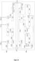
- Fig. 1a shows a schematic representation of a device according to the invention comprising two subsystems, namely a first subsystem ( 100 ) and a second subsystem ( 200 ).
- the first subsystem ( 100 ) includes a device for producing combustible hydrocarbon compounds ( 110 ) from carbon dioxide and / or carbon monoxide, and hydrogen as well as a transport system ( 121 ) for removing hydrogen from a first upstream storage device for hydrogen ( 126 ) and for supply of hydrogen to the device for producing combustible hydrocarbon compounds ( 110 ).
- the device for producing combustible hydrocarbon compounds ( 110 ) is preceded by the device for expanding carbon dioxide and / or carbon monoxide ( 142 ) via the transport system ( 122a ) for carbon dioxide and / or carbon monoxide, the device for expanding carbon dioxide and / or carbon monoxide ( 142 ) the storage device for carbon dioxide and/or carbon monoxide ( 127a ) is connected upstream.
- the device for producing flammable hydrocarbon compounds ( 110 ) is followed by a storage device for flammable hydrocarbon compounds ( 128a ), wherein the transport system ( 123a ) flammable hydrocarbon compounds from the storage device for flammable hydrocarbon compounds ( 128a ).
- the device for obtaining hydrogen and oxygen from water ( 130 ) which is fluidly connected to the storage device for hydrogen ( 126 ) via the transport system ( 121 ) for hydrogen.
- the device for producing hydrogen and oxygen from water ( 130 ) is also connected to an oxidant transport system ( 124a ), which oxidant is removed from the device for producing hydrogen and oxygen from water ( 130 ).
- the device for producing hydrogen and oxygen is available via the oxidizing agent ( 124a ).
- Water ( 130 ) is followed by a device for compressing the oxidizing agent ( 141 ) and this device for compressing the oxidizing agent ( 141 ) is followed by a storage device for oxidizing agent ( 125a ) via the transport system for oxidizing agent ( 124a ), the transport system for oxidizing agent ( 124a ). Oxidant is removed from the oxidant storage device ( 125a ).
- the second subsystem ( 200 ) includes an internal combustion engine ( 210 ) and a transport system for the transport system ( 123b ) for supplying flammable hydrocarbon compounds, wherein the transport system ( 123b ) is fluidly connected to a storage device for flammable hydrocarbon compounds ( 128b ), wherein the transport system ( 123b ) supplies flammable hydrocarbon compounds to the storage device for combustible hydrocarbon compounds ( 128b ).
- the internal combustion engine ( 210 ) is fluidly connected to a transport system ( 122b ) for removing an exhaust gas stream containing carbon dioxide and / or carbon monoxide and to a transport system ( 124b ) for supplying an oxidizing agent.
- the internal combustion engine ( 210 ) is preceded by the device for expanding the oxidizing agent ( 241 ) via the transport system ( 124b ); the internal combustion engine ( 210 ) is also connected via the transport system ( 122b ) for carbon dioxide and/or carbon monoxide to the device for expanding the oxidizing agent (241). 241 ) downstream; whereby the flow of carbon dioxide and/or carbon monoxide (exhaust gas flow) corresponds to the flow of the oxidizing agent via corresponding heat exchanger units ( 241e-h, see Fig. 2 ) supplies heat.
- An exhaust gas cooler ( 250 ) is connected downstream of these heat exchanger units ( 241e-h ) via the transport system ( 122b ) for carbon dioxide and/or carbon monoxide.
- This exhaust gas cooler ( 250 ) is followed by a division of the transport system ( 122b ) for carbon dioxide and/or carbon monoxide, wherein the stream of carbon dioxide and/or carbon monoxide is divided into two partial streams, with a first partial stream of the internal combustion engine ( 210 ) being recirculated and the second Partial flow is led to the device for compressing the exhaust gas flow ( 242 ). Subsequently, the transport system ( 122b ) for carbon dioxide and/or carbon monoxide removes the carbon dioxide and/or carbon monoxide from the device for compressing the exhaust gas stream ( 242 ) and becomes a heat exchanger ( 230 ).
- the heat exchanger ( 230 ) is also connected upstream of the device for expanding the oxidizing agent ( 241 ) via the transport system ( 124b ) for oxidizing agents.
- the transport system ( 122b ) for carbon dioxide and/or carbon monoxide and the transport system ( 124b ) for oxidizing agents are guided in parallel, which results in a heat exchange.
- the heat exchanger ( 230 ) is followed by a storage device for carbon dioxide and / or carbon monoxide ( 127b ), the transport system for carbon dioxide and / or carbon monoxide ( 122b ) carbon dioxide and / or carbon monoxide from the Storage device for carbon dioxide and / or carbon monoxide ( 127b ).
- the heat exchanger ( 230 ) is preceded by a storage device for oxidizing agents ( 125b ), the transport system supplying the transport system ( 124b ) for oxidizing agents to the storage device for oxidizing agents ( 125b ) oxidizing agents.
- the first subsystem ( 100 ) is in the Fig. 1 with the second subsystem ( 200 ) in one cycle in connection with one another by linking the transport systems ( 122a ) and ( 122b ) to ( 122b ); ( 124a ) and ( 124b ) to ( 124 ); ( 128a ) and ( 128b ) to ( 128 ), whereby subsystem ( 100 ) the subsystem ( 200 ) supplies combustible hydrocarbon compounds and oxidizing agents and subsystem ( 200 ) the subsystem ( 100 ) supplies carbon dioxide and / or carbon monoxide.
- Fig. 1b shows a schematic representation of an embodiment not according to the invention in Fig. 1a illustrated device in which the first subsystem ( 100 ) was modified. Accordingly, the subsystem ( 100 ) does not include a device for producing combustible hydrocarbon compounds ( 110 ) from carbon dioxide and/or carbon monoxide, and hydrogen.
- the transport system ( 121 ) for removing hydrogen from an upstream storage device for hydrogen ( 126 ) removes hydrogen from the storage device for hydrogen ( 126 ) and also from the subsystem ( 100 ).
- the transport system for carbon dioxide and/or carbon monoxide ( 122a ) carries carbon dioxide and/or carbon monoxide from the device for expanding carbon dioxide and/or carbon monoxide ( 142 ) and also from the subsystem ( 100 ).
- the transport system for combustible hydrocarbon compounds ( 123a ) supplies combustible hydrocarbon compounds from the outside to the storage device for combustible hydrocarbon compounds ( 128a ) and thus to the subsystem ( 100 ).
- Fig. 2 shows a schematic representation of the detailed structure of the device for expanding the oxidizing agent ( 241 ) and the device for compressing the exhaust gas flow ( 242 ) in the second subsystem ( 200 ), both devices being connected to one another via the mechanical or electrical coupling ( 243 ) for synergy -Usage are linked.
- oxidizing agent is fed via the transport system for oxidizing agent ( 124a ), whereby the stream of oxidizing agent is heated in the heat exchanger units ( 241e-h ) before it is transferred to the means for converting the expansion work into mechanical and/or or electrical work ( 241a-d ) comes to expansion.
- the exhaust gas stream from the internal combustion engine ( 210 ) is fed into the heat exchanger unit ( 241e-h ) as a heat exchanger medium via the transport system for carbon dioxide and/or carbon monoxide ( 122b ).
- the exhaust gas stream is guided via the transport system for carbon dioxide and/or carbon monoxide ( 122b ) through compression units ( 242a-d ); Intermediate cooling occurs by means of the intermediate cooling units ( 242e-h ), which are cooled by the heat exchanger units ( 260a-d ) via external air and/or water circuits.
- the example system given is divided into two subsystems (see Fig. 1 ).
- the first subsystem ( 100 ) is a stationary and/or mobile PtX production unit which covers the entire value chain of an e-fuel
- the second subsystem ( 200 ) represents a watercraft. Between the two Systems have an interface for exchanging operating materials.
- the combustion process of a ship's propulsion system (in this exemplary embodiment: container ship) is changed.
- a circular drive is used that works with an oxygen-carbon dioxide mixture and a synthetic/hydrocarbon-based fuel (and if necessary with additional water injection) and produces carbon dioxide and water vapor.
- intergases such as argon
- the cold and energy from the expansion of the cryogenic oxygen carried is used to compress and cool the resulting CO 2 for storage.
- the exhaust gas flow (possibly after the turbocharging generator and the exhaust gas heat recovery system) from the internal combustion engine ( 210 ) is used for the superheating of the oxygen by the heat exchanger units (see Fig. 2 , 241e, 241f, 241g, 241h ) of the device for expanding the oxidizing agent ( 241 ) by means of the transport system (122b) .
- Other heat sources within the internal combustion engine ( 210 ) can also be used to heat the oxygen, such as engine oil or cooling water or heat extraction from the CO 2 compression in the device for compressing the exhaust gas flow ( 242 ).
- the parallel material flow management enables the highest possible flow temperature in the respective heat exchanger.
- the gaseous oxygen in the heat exchanger units ( 241e, 241f, 241g, 241h ) experiences an increase in pressure.
- the oxygen in expansion turbines or the means for converting the expansion work into mechanical and/or electrical work ( 241a, 241b, 241c, 241d)
- it cools down and work is transferred to the turbine.
- the number and design of the heat exchanger units and expansion turbines depends on the respective thermodynamic optimum of the specific application.
- the exhaust gas stream consists largely of CO 2 and water vapor.
- no nitrogen from the ambient air is contained in the exhaust gas.
- the exhaust gas stream is led into an exhaust gas cooler ( 250 ) to separate the condensate.
- the exhaust gas cooler In order to provide the required cooling capacity, the exhaust gas cooler is cooled with a seawater circuit. The condensed water is separated off. In order to remove any residual amounts of water vapor, depending on the engine's compatibility, the exhaust gas must be compressed and cooled in order to separate further condensation water.
- the exhaust gas stream is divided into two partial streams.
- a partial flow is directed to the air intake of the internal combustion engine ( 210 ) (recirculation) (if necessary after further exhaust gas purification, for example with particle filters).
- Physical properties such as temperature and gas composition are recorded by sensors and transmitted to the control unit.
- the engine is supplied with the recirculated CO 2 from the exhaust gas stream and the gaseous oxygen from the device for expanding the oxidizing agent ( 241 ) for combustion.
- the oxygen is provided by appropriate storage devices ( 125b ), which are refueled before each journey.
- the partial exhaust gas flow that is not recirculated corresponds in balance to the CO 2 share from the fuel supplied.
- This is passed to a device for compressing the exhaust gas stream ( 242 ), a multistage compressor (ie comprising several compression units ( 242a-d )), with intermediate cooling.
- the compressor work required for the compressor(s) (see Fig. 2 ) is provided by the expansion work done by the oxygen in the device for expanding the oxidizing agent (241) .
- a coupling for the transfer of work must be guaranteed in order to realize the use of synergies.
- the coupling ( 243 ) can be done mechanically or electrically.
- the number and design of the heat exchanger and compression unit depends on the respective thermodynamic optimum of an application. Depending on the application, all components must be designed and aligned be coordinated.
- the compressed carbon dioxide in the individual stages is passed through the intermediate cooling units ( 242e-h ).
- Sea water can be used for cooling; depending on the temperature level, the cooling performance of expanding oxygen is also conceivable.
- the CO 2 is consequently brought into a thermodynamically favorable state for the subsequent liquefaction (condensation) in the device for compressing the exhaust gas stream ( 242 ).
- the gaseous compressed CO 2 is passed to the heat exchanger ( 230 ), which in the case of CO 2 represents a condensation unit.
- the heat is removed from the CO 2 until the phase transition occurs partially or completely.
- the heat is removed by the cryogenic, evaporating oxygen required for combustion, which is removed from the storage device for oxidizing agents ( 125b ).
- the liquefied CO 2 is then temporarily stored on board in a carbon dioxide storage device ( 127b ).
- bivalent storage options e.g. cryotanks
- CO 2 ( 127b ) and O 2 (125b) should be used if possible.
- a device must be installed to completely or partially empty the storage tanks and to reduce the degree of mixing of the substances.
- CO 2 that is as pure as possible is required as the input material.
- the tank on board the ship that was previously used as an oxygen storage unit can be pressurized with compressed CO 2 (from an intermediate stage of the compression process).
- the CO 2/ O 2 gas mixture can then be removed via a second valve and liquid CO 2 can then be fed into the tank. This is expected to result in a reduced O 2 content in the tank system.
- the removed CO 2 /O 2 gas mixture can be added to the recirculating CO 2 portion.
- a predefined amount of oxygen must be carried at the start of the journey.
- the oxygen carried is used for combustion and reduces over the journey time.
- the amount of CO 2 that is captured from the exhaust gas stream during the combustion process increases.
- Evaporating O 2 (boil-off) as a result of heating is preferably used for combustion in the internal combustion engine ( 210 ) or can be avoided or reduced by cooling.
- the electrical work for the gas transport system can be provided by using waste heat or by separate units.
- Subsystem ( 200 ) releases CO 2 to subsystem ( 100 ) and absorbs PtX fuel and oxygen.
- hydrogen and oxygen are created in an energy and material conversion process (primarily electrolysis process). This happens in the device for obtaining hydrogen and oxygen from water ( 130 ).
- the hydrogen produced is converted into synthetic fuels or combustible hydrocarbon compounds using the available CO 2 in a synthesis process (preferably the Fischer-Tropsch process or methanation). This happens in a corresponding device, namely the device for producing combustible hydrocarbon compounds from carbon dioxide and/or carbon monoxide and hydrogen ( 110 ).
- the process heat from the synthesis process in the device ( 110 ) can be used to heat the CO 2 in Device for the expansion of carbon dioxide ( 142 ) and / or for the water splitting process in the device ( 130 ) are transferred in thermal and / or electrical form.
- the water splitting process creates half the molecular amount of oxygen in addition to hydrogen.
- the CO 2 is expanded in an expansion turbine in the carbon dioxide expansion device ( 142 ). Both the mechanical work and the expansion cold can be used to compress the oxygen in the device for compressing the oxidizing agent ( 141 ) (analogous to the use of synergy in subsystem ( 200 )).
- the liquid oxygen and the synthetic fuel or the flammable hydrocarbon compounds are stored in the storage devices (125a) for oxidizing agents and the storage devices ( 128b ) for flammable hydrocarbon compounds and are available for refueling the watercraft (subsystem ( 200 )).
- CO 2 is delivered in liquid form to the PtX production facilities by a ship.
- the production systems can therefore be installed at locations with very good conditions for renewable energies (RE).
- Renewable energy priority regions along shipping routes should be highlighted. This means that there is no need for a complex delivery of fuel to the fuel buyer. Both onshore and offshore locations are possible, especially for wind energy locations.
- the proximity to the CO 2 source has no relevance since the CO 2 is provided and delivered by the PtX customer (fuel buyer, in this exemplary embodiment the watercraft).
- the exemplary embodiment 2 is designed analogously to the exemplary embodiment 1, but the exemplary embodiment 2 uses some modifications regarding the subsystem ( 100 ) (see Fig. 1b ). Accordingly, the exchange of operating materials and the process for exchanging the enthalpy differences remain, but the focus is on the system-internal production of hydrocarbon compounds and the device for producing combustible ones Hydrocarbon compounds made from carbon dioxide and/or carbon monoxide, and hydrogen ( 110 ) are omitted.
- the carbon dioxide delivered to subsystem ( 100 ) by subsystem ( 200 ) can therefore, if necessary, be temporarily stored after the enthalpy differences have been exchanged and sold on a carbon dioxide market.
- the hydrogen produced in the subsystem ( 100 ) by electrolysis in a device for obtaining hydrogen and oxygen from water ( 130 ) can be sold and the oxygen obtained can be liquefied as usual after using the enthalpy differences and fed to the subsystem ( 200 ).
- the required fuel is purchased and supplied from subsystem ( 100 ) to subsystem ( 200 ) analogously to exemplary embodiment 1 .
Description
Die vorliegende Erfindung betrifft eine Vorrichtung umfassend zwei Teilsysteme mit den Merkmalen von Anspruch 1. Zudem betrifft die vorliegende Erfindung ein Verfahren zum Betreiben der erfindungsgemäßen Vorrichtung mit den Merkmalen von Anspruch 8 sowie ein Verkehrsmittel mit den Merkmalen von Anspruch 13, umfassend das erste Teilsystem sowie das zweite Teilsystem der erfindungsgemäßen Vorrichtung.The present invention relates to a device comprising two subsystems with the features of claim 1. In addition, the present invention relates to a method for operating the device according to the invention with the features of claim 8 and a means of transport with the features of claim 13, comprising the first subsystem and the second subsystem of the device according to the invention.
Heutige Antriebskonzepte für mobile Anwendungen (im Straßen-, Schiffs- und Flugverkehr) basieren fast ausnahmslos auf einer fahrzeuginternen Oxidation von Kohlenwasserstoffen (z.B. Diesel, Benzin, Kerosin, Schweröl, Erdgas). Es wird hierbei zum größten Teil auf fossile Quellen zurückgegriffen. Für die Verbrennung wird der in der Umgebungsluft enthaltene Sauerstoff (O2) verwendet. Da in der Umgebungsluft neben O2 auch weitere Gase wie beispielsweise Stickstoff enthalten sind, sind diese ebenfalls im Abgasstrom vorhanden, u. a. als klimaschädliche Stickoxide (NOx).Today's drive concepts for mobile applications (in road, ship and air traffic) are almost exclusively based on the vehicle-internal oxidation of hydrocarbons (e.g. diesel, gasoline, kerosene, heavy oil, natural gas). For the most part, fossil sources are used. For combustion The oxygen (O 2 ) contained in the ambient air is used. Since the ambient air contains other gases such as nitrogen in addition to O 2 , these are also present in the exhaust gas stream, including as climate-damaging nitrogen oxides (NO x ).
Alternativen erfahren aktuell eine große Aufmerksamkeit, um THG-Emissionen zu reduzieren. Hervorzuheben sind vor allem elektrisch betriebene Fahrzeuge, die durch Weiterentwicklungen in der Batterietechnik (v. a. durch Lithium-lonen-Batterien) und in der Brennstoffzellentechnik vermehrt zum Einsatz kommen. Diese Fahrzeuge sind allerdings begrenzt in ihrer Reichweite und bedürfen einer Neugestaltung der Antriebstechnik und des Energieversorgungssystems (Ladesäulen, Wasserstofftankstellen). Zudem sind diese Konzepte in Fahrzeugen mit großem Frachtvolumen, langen Fahrzeiten und insbesondere hohen Energiebedarfen nach heutigem Stand der Technik nicht einsetzbar bzw. ökonomisch nicht sinnvoll.Alternatives are currently receiving a lot of attention to reduce GHG emissions. Particularly noteworthy are electrically powered vehicles, which are increasingly being used due to further developments in battery technology (especially lithium-ion batteries) and fuel cell technology. However, these vehicles have a limited range and require a redesign of the drive technology and the energy supply system (charging stations, hydrogen filling stations). In addition, these concepts cannot be used in vehicles with large cargo volumes, long travel times and, in particular, high energy requirements, given the current state of technology or do not make economic sense.
Dem heutigen Kenntnisstand nach zu beurteilen, werden auch langfristig für große Antriebskonzepte primär Verbrennungsmotoren eingesetzt. Um THG-Emissionen dieser Antriebskonzepte zu reduzieren, können E-Fuels (aus Power-to-X-Technologien, z. B.
Um den klimaschädlichen Effekt von Fahrzeugen mit Verbrennungsmotorweiter zu reduzieren wird vorgeschlagen (z.B.
Um dies zu ermöglichen kann das Konzept eines Kreislaufantriebs verwendet werden (
Das gespeicherte CO2 auf dem Fahrzeug kann zyklisch abgeführt werden und steht zur Weiterverarbeitung bereit. Für die Herstellung von synthetischen Kohlenwasserstoffen und deren Derivaten kann CO2 und H2 unter Bedingungen der Fischer-Tropsch-Synthese, oder anderen Katalysatoren, verwendet werden. Dieses Vorgehen wird beispielsweise in
Die Kombination der beschriebenen Punkte zur CO2 Abtrennung sowie zur Weiterverarbeitung zu neuen Kraftstoffen wird in
Um ein Versorgungssystem im Sinne einer Kreislaufwirtschaft sowohl technisch, als auch wirtschaftlich sinnvoll betreiben zu können, ist es nötig Synergien systemdienlich einzusetzen und energetisch zu nutzen. Diese systemische Betrachtung wird in den bestehenden Konzepten weitestgehend vernachlässigt.In order to be able to operate a supply system in the sense of a circular economy, both technically and economically, it is necessary to use synergies in a way that benefits the system and to use them energetically. This systemic view is largely neglected in existing concepts.
Die Bereitstellung von Sauerstoff durch eine Abtrennung aus der Umgebungsluft mittels Membranen (Bsp: MIEC-Membran) ist eine Möglichkeit, die nach
Die Direct Air Capture (DAC)-Technologie wird in aktuellen Diskussionen und Studien als mögliches Verfahren für einen bilanziellen Ausgleich der emittierten Menge an CO2 durch Fahrzeuge mit Verbrennungsmotor (o.Ä.) aufgeführt. Die DAC-Technologie erfordert allerdings einen großen Energieaufwand in Form von elektrischer und thermischer Energie um die benötigten CO2-Mengen herzustellen. Zudem ist noch nicht abzuschätzen, welche Auswirkungen DAC-Technologien auf die Umgebung (Flächenbedarf, ggf. Wasserbedarf, veränderte Luftzirkulation, Geräuschemissionen) bzw. Auswirkungen der Umgebung auf die DAC-Technologie und deren Lebensdauer (hohe Luftfeuchtigkeit, salzhaltige oder verunreinigte Luft) haben, sollten sie im Großmaßstab eingesetzt werden.Direct Air Capture (DAC) technology is listed in current discussions and studies as a possible method for balancing the amount of CO 2 emitted by vehicles with internal combustion engines (or similar). However, DAC technology requires a large amount of energy in the form of electrical and thermal energy to produce the required amounts of CO 2 . In addition, it is not yet possible to estimate what effects DAC technologies have on the environment (space requirement, possibly water requirement, changed air circulation, noise emissions) or effects of the environment on the DAC technology and its service life (high humidity, salty or contaminated air), they should be used on a large scale.
Das Betriebsstoffversorgungssystem aus
Die bereits erwähnte
Die
Die
Der vorliegenden Erfindung liegt die Aufgabe zugrunde, eine Vorrichtung sowie ein Verfahren zum Betreiben der Vorrichtung bereitzustellen, bei welcher eine CO2-Kreislaufwirtschaft, d.h. eine CO2-Abtrennung aus einer Verbrennungskraftmaschine sowie Weiterverarbeitung des CO2 zu brennbaren Kohlenwasserstoffen zum Betreiben der Verbrennungskraftmaschine, sowohl technisch als auch wirtschaftlich sinnvoll unter Ausnutzung von systemdienlichen Synergien innerhalb der Systemgrenzen realisiert wird.The present invention is based on the object of providing a device and a method for operating the device, in which a CO 2 cycle economy, ie CO 2 separation from an internal combustion engine and further processing of the CO 2 into combustible hydrocarbons for operating the internal combustion engine, both is implemented in a technically and economically sensible manner, taking advantage of system-serving synergies within the system boundaries.
Diese Aufgabe wird bezüglich einer Vorrichtung umfassend zwei Teilsysteme, d.h. ein erstes Teilsystem und ein zweites Teilsystem, mit den Merkmalen des Patentanspruchs 1 und bezüglich eines Verfahrens zum Betreiben der Vorrichtung mit den Merkmalen des Patentanspruchs 8 gelöst. In Patentanspruch 13 wird ein Verkehrsmittel umfassend das erste Teilsystem sowie das zweite Teilsystem angegeben. Die jeweiligen abhängigen Patentansprüche stellen dabei vorteilhafte Weiterbildungen dar.This task is related to a device comprising two subsystems, ie a first subsystem and a second subsystem, with the features of Patent claim 1 and with regard to a method for operating the device with the features of patent claim 8 solved. Claim 13 specifies a means of transport comprising the first subsystem and the second subsystem. The respective dependent patent claims represent advantageous further developments.
Erfindungsgemäß wird somit eine Vorrichtung umfassend zwei Teilsysteme bereitgestellt, wobei
- ein erstes Teilsystem (100) umfassend
- a) eine Vorrichtung zur Herstellung von brennbaren Kohlenwasserstoffverbindungen (110) aus Kohlenstoffdioxid und/oder Kohlenstoffmonoxid, und Wasserstoff;
- b) ein erstes Transportsystem (121) zur Abführung von Wasserstoff aus mindestens einer ersten vorgeschalteten Lagervorrichtung für Wasserstoff (126),
und- zur Zuführung von Wasserstoff zu der Vorrichtung zur Herstellung von brennbaren Kohlenwasserstoffverbindungen (110)
und/oder - zur Abführung von Wasserstoff aus der Vorrichtung umfassend zwei Teilsysteme;
- zur Zuführung von Wasserstoff zu der Vorrichtung zur Herstellung von brennbaren Kohlenwasserstoffverbindungen (110)
- c) ein zweites Transportsystem (122a) zur Zuführung von Kohlenstoffdioxid und/oder Kohlenstoffmonoxid zu der Vorrichtung zur Herstellung von brennbaren Kohlenwasserstoffverbindungen (110), wobei das Transportsystem (122a) zusätzlich ausgelegt ist der Vorrichtung umfassend zwei Teilsysteme Kohlenstoffdioxid und/oder Kohlenstoffmonoxid abzuführen;
- d) ein drittes Transportsystem (123a) zur Abführung von brennbaren Kohlenwasserstoffverbindungen aus der Vorrichtung zur Herstellung von brennbaren Kohlenwasserstoffverbindungen (110);
- sowie ein zweites Teilsystem (200), umfassend
- a) eine Verbrennungskraftmaschine (210);
- b) ein erstes Transportsystem (123b) zur Zuführung von brennbaren Kohlenwasserstoffverbindungen zu der Verbrennungskraftmaschine (210);
- c) ein zweites Transportsystem (124b) zur Zuführung eines Oxidationsmittels, bevorzugt eines flüssigen Oxidationsmittels, zu der Verbrennungskraftmaschine (210);
- d) ein drittes Transportsystem (122b) zur Abführung eines Kohlenstoffdioxid und/oder Kohlenstoffmonoxid enthaltenen Abgasstroms aus der Verbrennungskraftmaschine (210);
- e) einen Wärmetauscher (230) der in dritten Transportsystem (122b) angeordnet ist und dazu ausgelegt ist, dem Abgasstrom Wärme zu entziehen und diese dem Strom des Oxidationsmittels zuzuführen und Kohlenstoffdioxid und/oder Kohlenstoffmonoxid zu verflüssigen oder in eine überkritische Phase zu überführen;
- f) eine Vorrichtung zur Expansion des Oxidationsmittels (241), die fluidisch über das zweite Transportsystem (124b) des zweiten Teilsystems (200), zur Zuführung des Oxidationsmittels zu der Verbrennungskraftmaschine (210) des zweiten Teilsystems (200), mit der Verbrennungskraftmaschine (210) des zweiten Teilsystems (200) verbunden und dieser vorgeschaltet ist, wobei die Vorrichtung zur Expansion des Oxidationsmittels (241) des zweiten Teilsystems (200) mindestens ein Mittel zur Umwandlung der Expansionsarbeit des Oxidationsmittels in mechanische und/oder elektrische Arbeit umfasst;
- g) eine Vorrichtung zur Komprimierung des Abgasstroms (242), die fluidisch über das dritte Transportsystem (122b) des zweiten Teilsystems (200), zur Abführung des Abgasstroms aus der Verbrennungskraftmaschine (210) des zweiten Teilsystems (200), mit der Verbrennungskraftmaschine (210) des zweiten Teilsystems (200) verbunden und dieser nachgeschaltet ist, wobei die Vorrichtung zur Komprimierung des Abgasstroms (242) des zweiten Teilsystems (200) mindestens eine Komprimierungseinheit umfasst;
- wobei die Vorrichtung zur Expansion des Oxidationsmittels (241) des zweiten Teilsystems (200) und die Vorrichtung zur Komprimierung des Abgasstroms (242) des zweiten Teilsystems (200) mechanisch oder elektrisch miteinander gekoppelt sind,
- wobei
- zumindest ein Teil der geleisteten Expansionsarbeit über das mindestens eine Mittel der Vorrichtung zur Expansion des Oxidationsmittels (241) des zweiten Teilsystems (200) zur Umwandlung der Expansionsarbeit des Oxidationsmittels in mechanische und/oder elektrische Arbeit in mechanische und/oder elektrische Arbeit umgewandelt wird und diese über die mechanische und/oder elektrische Koppelung der Vorrichtung zur Expansion des Oxidationsmittels (241) des zweiten Teilsystems (200) mit der Vorrichtung zur Komprimierung des Abgasstroms (242) des zweiten Teilsystems (200) an die Vorrichtung zur Komprimierung des Abgasstroms (242) des zweiten Teilsystems (200) abgegeben wird und zumindest einen Teil der zur Komprimierung des Abgasstroms benötigten Verdichterarbeit leistet,
und/oder - zumindest ein Teil der für die Expansion des Oxidationsmittels benötigten Wärme durch die bei der Komprimierung des Abgasstroms in der Vorrichtung zur Komprimierung des Abgasstroms (242) des zweiten Teilsystems (200) entstehende Wärme der Vorrichtung zur Expansion des Oxidationsmittels (241) des zweiten Teilsystems (200) bereitgestellt wird;
- in einem Zyklus miteinander in Verbindung steht oder in Verbindung bringbar ist durch Verknüpfung
- a) des zweiten Transportsystems (122a) des ersten Teilsystems (100), zur Zuführung von Kohlenstoffdioxid und/oder Kohlenstoffmonoxid zu der Vorrichtung zur Herstellung von brennbaren Kohlenwasserstoffverbindungen (110) des ersten Teilsystems (100), und des dritten Transportsystems (122b) des zweiten Teilsystems (200) zur Abführung eines Kohlenstoffdioxid und/oder Kohlenstoffmonoxid enthaltenen Abgasstrom aus der Verbrennungskraftmaschine (210) des zweiten Teilsystems (200), zu einem Transportsystem (122) sowie
- b) des dritten Transportsystems (123a) des ersten Teilsystems (100), zur Abführung von brennbaren Kohlenwasserstoffverbindungen aus der Vorrichtung zur Herstellung von brennbaren Kohlenwasserstoffverbindungen (110) des ersten Teilsystems (100), und des ersten Transportsystems (123b) des zweiten Teilsystems (200), zur Zuführung von brennbaren Kohlenwasserstoffverbindungen zu der Verbrennungskraftmaschine (210) des zweiten Teilsystems (200), zu einem Transportsystem (123);
- a first subsystem ( 100 ).
- a) a device for producing combustible hydrocarbon compounds ( 110 ) from carbon dioxide and/or carbon monoxide, and hydrogen;
- b) a first transport system ( 121 ) for removing hydrogen from at least one first upstream storage device for hydrogen ( 126 ),
and- for supplying hydrogen to the device for producing flammable hydrocarbon compounds ( 110 )
and or - for removing hydrogen from the device comprising two subsystems;
- for supplying hydrogen to the device for producing flammable hydrocarbon compounds ( 110 )
- c) a second transport system ( 122a ) for supplying carbon dioxide and / or carbon monoxide to the device for producing combustible hydrocarbon compounds ( 110 ), wherein the transport system ( 122a ) is additionally designed to remove carbon dioxide and / or carbon monoxide from the device comprising two subsystems;
- d) a third transport system ( 123a ) for removing combustible hydrocarbon compounds from the device for producing combustible hydrocarbon compounds ( 110 );
- and a second subsystem ( 200 ), comprising
- a) an internal combustion engine ( 210 );
- b) a first transport system ( 123b ) for supplying combustible hydrocarbon compounds to the internal combustion engine ( 210 );
- c) a second transport system ( 124b ) for supplying an oxidizing agent, preferably a liquid oxidizing agent, to the internal combustion engine ( 210 );
- d) a third transport system ( 122b ) for removing an exhaust gas stream containing carbon dioxide and/or carbon monoxide from the internal combustion engine ( 210 );
- e) a heat exchanger ( 230 ) which is arranged in the third transport system (122b) and is designed to remove heat from the exhaust gas stream and to supply it to the stream of oxidizing agent and to liquefy carbon dioxide and/or carbon monoxide or to convert it into a supercritical phase;
- f) a device for expanding the oxidizing agent ( 241 ), which flows fluidly via the second transport system (124b) of the second subsystem ( 200 ), for supplying the oxidizing agent to the internal combustion engine ( 210 ) of the second subsystem ( 200 ), with the internal combustion engine ( 210 ) of the second subsystem ( 200 ) and connected upstream thereof, wherein the device for expanding the oxidizing agent ( 241 ) of the second subsystem ( 200 ) comprises at least one means for converting the expansion work of the oxidizing agent into mechanical and / or electrical work;
- g) a device for compressing the exhaust gas stream ( 242 ), which is fluidically connected via the third transport system ( 122b ) of the second subsystem ( 200 ), for discharging the exhaust gas stream from the internal combustion engine ( 210 ) of the second subsystem ( 200 ), with the internal combustion engine ( 210 ) of the second subsystem ( 200 ) and is connected downstream, the device for compressing the exhaust gas flow ( 242 ) of the second subsystem ( 200 ) comprising at least one compression unit;
- wherein the device for expanding the oxidizing agent ( 241 ) of the second subsystem ( 200 ) and the device for compressing the exhaust gas stream ( 242 ) of the second subsystem ( 200 ) are mechanically or electrically coupled to one another,
- where
- at least some of the expansion work done over the minimum a means of the device for expanding the oxidizing agent ( 241 ) of the second subsystem ( 200 ) for converting the expansion work of the oxidizing agent into mechanical and / or electrical work and this via the mechanical and / or electrical coupling of the Device for expanding the oxidizing agent ( 241 ) of the second subsystem ( 200 ) with the device for compressing the exhaust gas flow ( 242 ) of the second subsystem ( 200 ) to the device for compressing the exhaust gas flow ( 242 ) of the second subsystem ( 200 ) is delivered and at least provides part of the compressor work required to compress the exhaust gas flow,
and or - at least part of the heat required for the expansion of the oxidizing agent is due to the heat of the device for expanding the oxidizing agent ( 241 ) of the second subsystem ( 200 ) generated during the compression of the exhaust gas stream in the device for compressing the exhaust gas flow ( 242 ) of the second subsystem ( 200 ). ) provided;
- is connected to one another in a cycle or can be connected by linking
- a) the second transport system ( 122a ) of the first subsystem ( 100 ), for supplying carbon dioxide and/or carbon monoxide to the device for producing combustible hydrocarbon compounds ( 110 ) of the first subsystem ( 100 ), and the third transport system (122b) of the second Subsystem ( 200 ) for discharging an exhaust gas stream containing carbon dioxide and / or carbon monoxide from the internal combustion engine ( 210 ) of the second subsystem ( 200 ), to a transport system ( 122 ) and
- b) the third transport system ( 123a ) of the first subsystem ( 100 ), for removing flammable hydrocarbon compounds from the device for producing flammable hydrocarbon compounds ( 110 ) of the first subsystem ( 100 ), and the first transport system ( 123b ) of the second subsystem ( 200 ), for supplying combustible hydrocarbon compounds to the internal combustion engine ( 210 ) of the second subsystem ( 200 ), to a transport system ( 123 );
Die Vorrichtung in zwei Teilsysteme zu unterteilen, wobei diese in Verbindung stehen oder in Verbindung bringbar sind, ermöglicht es, die jeweiligen Teilsysteme unabhängig voneinander zu betreiben. Beide Teilsysteme könnten dabei jeweils stationär und/oder mobil ausgeführt sein. Die Kombination beider Teilsysteme miteinander ermöglicht hingegen eine kohlenstoffbasierte Kreislaufwirtschaft (CO2 und/oder CO), die durch einen Stoffaustausch zwischen den Teilsystemen realisiert wird.Dividing the device into two subsystems, which are connected or can be connected, makes it possible to operate the respective subsystems independently of one another. Both subsystems could be designed to be stationary and/or mobile. The combination of both subsystems, however, enables a carbon-based circular economy (CO 2 and/or CO), which is realized through a mass exchange between the subsystems.
Beispielsweise wäre denkbar das Gesamtsystem als Fahrzeug angetrieben durch einen Motor, in Gestalt der Verbrennungskraftmaschine (210), auszuführen. Durch in Verbindungbringen der beiden Teilsysteme über die Verknüpfung der entsprechenden Transportsysteme kann das Teilsystem (100) dem Teilsystem (200) bzw. der darin enthaltenen Verbrennungskraftmaschine (210) die notwendigen brennbaren Kohlenwasserstoffe, d.h. einen Kraftstoff, zuführen. Teilsystem (200) kann dem Teilsystem (100) anschließend das bei dem Verbrennungsvorgang freiwerdende CO2 und/oder Kohlenstoffmonoxid, welches seinerseits in der Vorrichtung zur Herstellung von brennbaren Kohlenwasserstoffverbindungen (110) aus Kohlenstoffdioxid und/oder Kohlenstoffmonoxid sowie Wasserstoff des Teilsystems (100) umgesetzt wird, nach Abscheidung zuführen und schließlich den Kreislauf schließen. Bei dem für den Verbrennungsvorgang in der Verbrennungskraftmaschine (210) des Teilsystems (200) notwendigen Oxidationsmittel kann es sich um Sauerstoff, welcher aus der Umgebungsluft gewonnen wird und bevorzugt vor Eintrag in die Verbrennungskraftmaschine (210) durch ein Abscheidungsverfahren von anderen Bestandteilen separiert wird, handeln.For example, it would be conceivable to design the entire system as a vehicle driven by an engine, in the form of the internal combustion engine ( 210 ). By connecting the two subsystems via linking the corresponding transport systems, the subsystem ( 100 ) can supply the necessary combustible hydrocarbons, ie a fuel, to the subsystem ( 200 ) or the internal combustion engine ( 210 ) contained therein. Subsystem ( 200 ) can then supply the subsystem ( 100 ) with the CO 2 and/or carbon monoxide released during the combustion process, which in turn is implemented in the device for producing combustible hydrocarbon compounds ( 110 ) from carbon dioxide and/or carbon monoxide and hydrogen of the subsystem ( 100 ). after separation and finally close the circuit. The oxidizing agent required for the combustion process in the internal combustion engine ( 210 ) of the subsystem ( 200 ) can be oxygen, which is obtained from the ambient air and is preferably separated from other components by a deposition process before being introduced into the internal combustion engine ( 210 ). .
Um diese zugrundeliegende kohlenstoffbasierte Kreislaufwirtschaft möglichst effizient und/oder ein temporär voneinander unabhängiges Betreiben der beiden Teilsysteme zu gestalten, müssen die zwischen den Teilsystemen getauschten Stoffe, insbesondere das Oxidationsmittel sowie das CO2 und/oder das Kohlenstoffmonoxid, vor und nach den Umsetzungsprozessen entsprechend für die jeweilige Verwendung thermodynamisch günstig aufbereitet werden. Gemäß der vorliegenden Erfindung wird dieses durch Anwendung eines Wärmetauschers (230), welcher dazu ausgelegt ist dem Abgasstrom Wärme zu entziehen und diese dem Strom des Oxidationsmittels zuzuführen, realisiert. Durch Übertragung der Enthalpie-Differenzen ist eine Synergie-Nutzung zwischen dem Abgasstrom und dem Strom des Oxidationsmittels in Teilsystem (200) möglich. Die Überführung der Stoffe von einem Teilsystem auf das jeweils andere erfolgt durch entsprechende Transportsysteme, wie z.B. Pipelines.In order to make this underlying carbon-based circular economy as efficient as possible and/or to temporarily operate the two subsystems independently of each other, the substances exchanged between the subsystems, in particular the oxidizing agent as well as the CO 2 and/or the carbon monoxide, must be used accordingly before and after the implementation processes respective use thermodynamically favorably prepared become. According to the present invention, this is realized by using a heat exchanger ( 230 ), which is designed to remove heat from the exhaust gas stream and supply it to the stream of oxidizing agent. By transferring the enthalpy differences, synergy utilization between the exhaust gas flow and the flow of the oxidizing agent in subsystem ( 200 ) is possible. The transfer of materials from one subsystem to the other takes place using appropriate transport systems, such as pipelines.
Das durch Teilsystem (200) an Teilsystem (100) angelieferte CO2 kann nach dem Austausch gegebenenfalls zwischengespeichert und an einem CO2-Markt veräußert werden.The CO 2 delivered to subsystem ( 100 ) by subsystem ( 200 ) can, if necessary, be temporarily stored after the exchange and sold on a CO 2 market.
Eine bevorzugte Variante der erfindungsgemäßen Vorrichtung zeichnet sich dadurch aus, dass im Wärmetauscher (230) der Abgasstrom und der Strom des Oxidationsmittels parallel geführt werden.A preferred variant of the device according to the invention is characterized in that the exhaust gas flow and the flow of the oxidizing agent are conducted in parallel in the heat exchanger ( 230 ).
Die parallele Stoffstromführung ist förderlich für die Übertragung der Enthalpie-Differenzen, was die kohlenstoffbasierte Kreislaufwirtschaft effizienter gestaltet, und ermöglicht zudem eine möglichst hohe Vorlauftemperatur in dem Wärmetauscher.The parallel material flow is beneficial for the transfer of enthalpy differences, which makes the carbon-based circular economy more efficient, and also enables the highest possible flow temperature in the heat exchanger.
Die erfindungsgemäße Vorrichtung zeichnet sich dadurch aus, dass der Wärmetauscher (230) ausgelegt ist, Kohlenstoffdioxid und/oder Kohlenstoffmonoxid zu verflüssigen oder in eine überkritische Phase zu überführen.The device according to the invention is characterized in that the heat exchanger ( 230 ) is designed to liquefy carbon dioxide and/or carbon monoxide or to convert it into a supercritical phase.
Um CO2 und/oder Kohlenstoffmonoxid effizient abscheiden und speichern zu können, also das CO2 und/oder Kohlenstoffmonoxid des Abgasstroms möglichst bilanziell dem der Verbrennungskraftmaschine (210) zugeführten Kraftstoff entspricht, ist es vorteilhaft diesen zu verflüssigen oder in eine überkritische Phase zu überführen. CO2 und/oder Kohlenstoffmonoxid kann somit Teilsystem (100) durch das Teilsystem (200) in flüssiger oder überkritischer Form angeliefert werden. Teilsystem (100) kann folglich an Standorten mit bevorzugt guter EE (Erneuerbaren Energien) -Ressource installiert werden, ohne auf eine zusätzliche/externe CO2-Versorgung angewiesen zu sein. Der Wärmetauscher (230) kann beispielsweise als Phasentauscher fungieren, indem dieser CO2 verflüssigt und das Oxidationsmittel, sofern selbiges flüssig zugegeben wird, verdampft.In order to be able to capture and store CO 2 and/or carbon monoxide efficiently, i.e. the CO 2 and/or carbon monoxide of the exhaust gas stream corresponds as closely as possible to the fuel supplied to the internal combustion engine ( 210 ), it is advantageous to liquefy it or convert it into a supercritical phase. CO 2 and/or carbon monoxide can thus be delivered to subsystem ( 100 ) by subsystem ( 200 ) in liquid or supercritical form. Subsystem ( 100 ) can therefore be installed at locations with preferably good EE (renewable energy) resources, without having to rely on an additional/external CO 2 supply. The heat exchanger ( 230 ) can, for example, function as a phase exchanger by CO 2 liquefies and the oxidizing agent, if it is added in liquid form, evaporates.
Eine weitere bevorzugte Variante der erfindungsgemäßen Vorrichtung zeichnet sich dadurch aus, dass der Wärmetauscher (230) ein Rohrbündelwärmetauscher, ein Plattenwärmetauscher oder ein Hybridwärmetauscher ist.A further preferred variant of the device according to the invention is characterized in that the heat exchanger ( 230 ) is a tube bundle heat exchanger, a plate heat exchanger or a hybrid heat exchanger.
Diese Ausführungsformen des Wärmetauschers (230) ermöglichen eine effiziente parallele Stoffstromführung, wodurch die Synergie-Nutzung effektiver erfolgt.These embodiments of the heat exchanger ( 230 ) enable efficient parallel material flow management, whereby the synergy is used more effectively.
Die erfindungsgemäße Vorrichtung zeichnet sich dadurch aus, dass das zweite Teilsystem (200) eine Vorrichtung zur Expansion des Oxidationsmittels (241) enthält, die fluidisch über das Transportsystem (124b), zur Zuführung des Oxidationsmittels zu der Verbrennungskraftmaschine (210), mit der Verbrennungskraftmaschine (210) verbunden und dieser vorgeschaltet ist sowie bevorzugt dem Wärmetauscher (230) nachgeschaltet ist.The device according to the invention is characterized in that the second subsystem ( 200 ) contains a device for expanding the oxidizing agent ( 241 ), which fluidly via the transport system ( 124b ), for supplying the oxidizing agent to the internal combustion engine ( 210 ), with the internal combustion engine ( 210 ) is connected and this is connected upstream and preferably downstream of the heat exchanger ( 230 ).
Durch die Vorrichtung zur Expansion des Oxidationsmittels (241) erhält das Oxidationsmittel durch Erwärmung zunächst eine Druckerhöhung und wird anschließend in der Vorrichtung zur Expansion des Oxidationsmittels (241) expandiert; dadurch wird das Oxidationsmittel auf die für die Verbrennung bevorzugten thermodynamischen Bedingungen (Temperatur, Druck) gebracht.Through the device for expanding the oxidizing agent ( 241 ), the oxidizing agent first receives a pressure increase through heating and is then expanded in the device for expanding the oxidizing agent ( 241 ); This brings the oxidizing agent to the thermodynamic conditions (temperature, pressure) preferred for combustion.
Die erfindungsgemäße Vorrichtung zeichnet sich dadurch aus, dass die Vorrichtung zur Expansion des Oxidationsmittels (241) mindestens ein Mittel zur Umwandlung der Expansionsarbeit des Oxidationsmittels in mechanische und/oder elektrische Arbeit, zum Beispiel mindestens eine Expansionsturbine, bevorzugt mehrere Expansionsturbinen, die zu einer Kaskade angeordnet sind, umfasst.The device according to the invention is characterized in that the device for expanding the oxidizing agent ( 241 ) has at least one means for converting the expansion work of the oxidizing agent into mechanical and/or electrical work, for example at least one expansion turbine, preferably several expansion turbines, which are arranged in a cascade are included.
Das Oxidationsmittel wird in den Expansionsturbinen expandiert. Die dabei verrichtete Arbeit kann beispielsweise mechanisch oder elektrisch übertragen werden und steht dann für weitere Synergie-Nutzungen zur Verfügung. Die kaskadenartige Anordnung der Expansionsturbinen ermöglicht eine Expansion des Oxidationsmittels über mehrere Stufen, wodurch dieses auf die für die Verbrennung optimalen thermodynamischen Bedingungen (Temperatur, Druck) gebracht werden kann. Die Anzahl und Ausführung der Expansionsturbinen ist vom thermodynamischen Optimum des Anwendungsfalls abhängig.The oxidizer is expanded in the expansion turbines. The work carried out can, for example, be transferred mechanically or electrically and is then available for further synergy uses. The cascade-like arrangement of the expansion turbines enables the oxidizer to expand over several stages, which brings it to the required level Combustion can be brought to optimal thermodynamic conditions (temperature, pressure). The number and design of the expansion turbines depends on the thermodynamic optimum of the application.
Die erfindungsgemäße Vorrichtung zeichnet sich dadurch aus, dass das zweite Teilsystem (200) eine Vorrichtung zur Komprimierung des Abgasstroms (242) enthält, die fluidisch über das Transportsystem (122b), zur Abführung des Abgasstroms aus der Verbrennungskraftmaschine (210), mit der Verbrennungskraftmaschine (210) verbunden und dieser nachgeschaltet ist, wobei die Vorrichtung (242) bevorzugt durch einen externen Luft- und/oder Wasserkreislauf gekühlt wird.The device according to the invention is characterized in that the second subsystem ( 200 ) contains a device for compressing the exhaust gas flow ( 242 ), which is fluidically connected via the transport system ( 122b ) to the exhaust gas flow from the internal combustion engine ( 210 ), with the internal combustion engine ( 210 ) and is connected downstream, the device ( 242 ) preferably being cooled by an external air and/or water circuit.
Durch die Vorrichtung zur Komprimierung des Abgasstroms (242) wird der Abgasstrom vor Eintrag in den Wärmetauscher (230) in Bezug auf Temperatur und Druck aufbereitet, wodurch der Wärmeaustausch im Wärmetauscher (230) effizienter ausgeführt wird. Zudem steht die bei der Komprimierung entstehende Wärme für weitere Synergie-Nutzungen zur Verfügung.By means of the device for compressing the exhaust gas stream ( 242 ), the exhaust gas stream is processed in terms of temperature and pressure before it enters the heat exchanger ( 230 ), whereby the heat exchange in the heat exchanger ( 230 ) is carried out more efficiently. In addition, the heat generated during compression is available for further synergy uses.
Die erfindungsgemäße Vorrichtung zeichnet sich dadurch aus, dass die Vorrichtung zur Komprimierung des Abgasstroms (242) mindestens eine Komprimierungseinheit, bevorzugt mehrere Komprimierungseinheiten, die zu einer Kaskade angeordnet sind, umfasst, wobei bevorzugt zwischen den einzelnen Komprimierungsstufen eine Zwischenkühlung durch einen externen Luft- und/oder Wasserkreislauf erfolgt.The device according to the invention is characterized in that the device for compressing the exhaust gas stream ( 242 ) comprises at least one compression unit, preferably several compression units, which are arranged in a cascade, with intermediate cooling preferably being carried out between the individual compression stages by an external air and/or or water cycle takes place.
Die kaskadenartige Anordnung der Komprimierungseinheiten ermöglicht eine vorteilhafte Komprimierung des Abgasstroms über mehrere Stufen. Die Anzahl und Ausführung der Komprimierungseinheiten ist vom thermodynamischen Optimum des Anwendungsfalls abhängig. Die Zwischenkühlung mittels des externen Luft- und/oder Wasserkreislauf kann über integrierte Wärmetauscher erfolgen. Diese integrierten Wärmetauscher können beispielsweise unter der Annahme, dass Teilsystem (200) ein Wasserfahrzeug ist, Wasser aus der Umgebung verwenden; analog kann auch Umgebungsluft zur Zwischenkühlung dienen.The cascade-like arrangement of the compression units enables advantageous compression of the exhaust gas flow over several stages. The number and design of the compression units depends on the thermodynamic optimum of the application. Intercooling using the external air and/or water circuit can take place via integrated heat exchangers. These integrated heat exchangers can, for example, use water from the environment assuming that subsystem ( 200 ) is a watercraft; Analogously, ambient air can also be used for intermediate cooling.
Die erfindungsgemäße Vorrichtung zeichnet sich dadurch aus, dass die Vorrichtung zur Expansion des Oxidationsmittels (241) und die Vorrichtung zur Komprimierung des Abgasstroms (242) mechanisch oder elektrisch miteinander gekoppelt sind,
wobei
- zumindest ein Teil der geleisteten Expansionsarbeit über das mindestens eine Mittel der Vorrichtung (241) zur Umwandlung der Expansionsarbeit des Oxidationsmittels in mechanische und/oder elektrische Arbeit in mechanische und/oder elektrische Arbeit umgewandelt wird und diese über die mechanische und/oder elektrische Koppelung der Vorrichtung (241) mit der Vorrichtung zur Komprimierung des Abgasstroms (242) an die Vorrichtung zur Komprimierung des Abgasstroms (242) abgegeben wird
- und zumindest einen Teil der zur Komprimierung des Abgasstroms benötigten Verdichterarbeit leistet,
und/oder - zumindest ein Teil der für die Expansion des Oxidationsmittels benötigten Wärme durch die bei der Komprimierung des Abgasstroms in der Vorrichtung zur Komprimierung des Abgasstroms (242) entstehende Wärme der Vorrichtung (241) bereitgestellt wird.
where
- at least part of the expansion work done is converted into mechanical and/or electrical work via the at least one means of the device ( 241 ) for converting the expansion work of the oxidizing agent into mechanical and/or electrical work and this via the mechanical and/or electrical coupling of the device ( 241 ) is delivered to the device for compressing the exhaust gas flow ( 242 ) with the device for compressing the exhaust gas stream ( 242 ).
- and performs at least part of the compressor work required to compress the exhaust gas flow,
and or - at least part of the heat required for the expansion of the oxidizing agent is provided by the heat of the device ( 241 ) generated during the compression of the exhaust gas stream in the device for compressing the exhaust gas stream ( 242 ).
Die mechanische oder elektrische Kopplung der Vorrichtung zur Expansion des Oxidationsmittels (241) und der Vorrichtung zur Komprimierung des Abgasstroms (242) miteinander ermöglicht eine weitere Verknüpfung der Energie- und Stoffströme des CO2 und/oder Kohlenstoffmonoxid mit denen des Oxidationsmittels innerhalb der Systemgrenzen zusätzlich zur parallelen Stoffstromführung wie sie bereits im Wärmetauscher (230) vollzogen wird.The mechanical or electrical coupling of the device for expanding the oxidizing agent ( 241 ) and the device for compressing the exhaust gas stream ( 242 ) with one another enables a further linking of the energy and material flows of CO 2 and/or carbon monoxide with those of the oxidizing agent within the system boundaries in addition to parallel material flow management as is already carried out in the heat exchanger ( 230 ).
Die Kopplung zur Übertragung der Expansionsarbeit kann dabei gewährleisteten, dass die beabsichtigte Synergie durch gegenseitige Enthalpie-Nutzung realisiert wird. Anzahl und Ausführung der Expansionsturbinen und Komprimierungseinheiten ist vom jeweiligen thermodynamischen Optimum des Anwendungsfalls abhängig. Je nach Anwendungsfall werden alle Komponenten ausgelegt und aufeinander abgestimmt.The coupling to transfer the expansion work can ensure that the intended synergy is realized through mutual enthalpy utilization. The number and design of the expansion turbines and compression units depends on the respective thermodynamic optimum of the application. Depending on the application, all components are designed and coordinated with one another.
Eine weitere bevorzugte Variante der erfindungsgemäßen Vorrichtung zeichnet sich dadurch aus, dass die Vorrichtung zur Expansion des Oxidationsmittels (241) mindestens einen Wärmetauscher umfasst, der dazu ausgelegt ist, dem Abgasstrom unmittelbar nach dessen Abführung aus der Verbrennungskraftmaschine (210) durch das Transportsystem (122b), Abwärme zu entziehen und dem Strom des Oxidationsmittels zuzuführen.A further preferred variant of the device according to the invention is characterized in that the device for expanding the oxidizing agent ( 241 ) comprises at least one heat exchanger which is designed to supply the exhaust gas stream immediately after it has been discharged from the internal combustion engine ( 210 ) through the transport system ( 122b ). , to remove waste heat and add it to the oxidizing agent stream.
Folglich wird ein aus der Verbrennungskraftmaschine (210) ausgekoppelter Wärmestrom für die Erwärmung des Oxidationsmittels für die Druckerhöhung verwendet. Dabei kann um eine möglichst hohe Eingangstemperatur des Abgasstroms, also des Primärwärmetauschermediums, zu erhalten, bevorzugt eine parallele Abgaszuführung zu den einzelnen Wärmetauschern ausgeführt werden.Consequently, a heat flow extracted from the internal combustion engine ( 210 ) is used to heat the oxidizing agent to increase the pressure. In order to obtain the highest possible inlet temperature of the exhaust gas stream, i.e. the primary heat exchanger medium, a parallel exhaust gas supply to the individual heat exchangers can preferably be carried out.
Eine weitere bevorzugte Variante der erfindungsgemäßen Vorrichtung zeichnet sich dadurch aus, dass der Vorrichtung zur Komprimierung des Abgasstroms (242) ein Abgaskühler (250), der bevorzugt durch einen externen Luft- und/oder Wasserkreislauf gekühlt wird, über das Transportsystem (122b) vorgeschaltet ist, der im Abgasstrom enthaltenes Wasser kondensiert und abtrennt.A further preferred variant of the device according to the invention is characterized in that the device for compressing the exhaust gas stream ( 242 ) is preceded by an exhaust gas cooler ( 250 ), which is preferably cooled by an external air and/or water circuit, via the transport system ( 122b ). , which condenses and separates water contained in the exhaust gas stream.
Die durch diesen Schritt durchgeführte Abscheidung des Kondensats dient zur Zwischenreinigung und optimiert somit die Folgeschritte des Abgasstroms bzw. des Stroms des CO2 und/oder Kohlenstoffmonoxid, also die Verfahrensschritte in der Vorrichtung zur Komprimierung des Abgasstroms (242) sowie in dem Wärmetauscher (230).The separation of the condensate carried out in this step serves for intermediate cleaning and thus optimizes the subsequent steps of the exhaust gas flow or the flow of CO 2 and/or carbon monoxide, i.e. the process steps in the device for compressing the exhaust gas flow ( 242 ) and in the heat exchanger ( 230 ) .
Eine weitere bevorzugte Variante der erfindungsgemäßen Vorrichtung zeichnet sich dadurch aus, dass im zweiten Teilsystem (200) der Abgasstrom, bevorzugt zwischen dem Abgaskühler (250) und der Vorrichtung zur Komprimierung des Abgasstroms (242), in zwei Teilströme aufgeteilt wird, wobei ein erster Teilstrom der Vorrichtung zur Komprimierung des Abgasstroms (242) über das Transportsystem (122b) zugeführt wird und ein zweiter Teilstrom zu der Verbrennungskraftmaschine (210) über das Transportsystem (122c) rezirkuliert und dem Oxidationsmittel als inerter Anteil zugeführt wird, wobei die Aufteilung bevorzugt nach Abtrennung von Wasser aus dem Abgasstrom erfolgt.A further preferred variant of the device according to the invention is characterized in that in the second subsystem ( 200 ) the exhaust gas flow, preferably between the exhaust gas cooler ( 250 ) and the device for compressing the exhaust gas flow ( 242 ), is divided into two partial flows, with a first partial flow the device for compressing the exhaust gas stream ( 242 ) via the transport system ( 122b ) is supplied and a second partial stream is recirculated to the internal combustion engine ( 210 ) via the transport system ( 122c ) and supplied to the oxidizing agent as an inert portion, the Division preferably takes place after separation of water from the exhaust gas stream.
Durch die vorgeschlagene Rezirkulation wird ermöglicht, dass der Abgasstrom und/oder das Produktgas zum größten Teil aus CO2 und/oder Kohlenstoffmonoxid, Wasserdampf und/oder ggfs. anderen Inertgasen bestehen; anstelle von Umgebungsluft wird der Verbrennung neben dem eigentlichen Kraftstoff und dem Oxidationsmittel, CO2 und/oder Kohlenstoffmonoxid als inerter Anteil erneut hinzugefügt. Im Gegensatz zum regulären Verbrennungsbetrieb eines Motors ist bevorzugt kein Stickstoff aus der Umgebungsluft im Abgas und/oder Produktgas enthalten. Folglich werden THG-Emissionen durch NOx umgangen.The proposed recirculation makes it possible for the exhaust gas stream and/or the product gas to consist largely of CO 2 and/or carbon monoxide, water vapor and/or possibly other inert gases; Instead of ambient air, in addition to the actual fuel and the oxidizing agent, CO 2 and/or carbon monoxide are added again to the combustion as an inert component. In contrast to the regular combustion operation of an engine, preferably no nitrogen from the ambient air is contained in the exhaust gas and/or product gas. Consequently, GHG emissions are bypassed by NO x .
Eine weitere bevorzugte Variante der erfindungsgemäßen Vorrichtung zeichnet sich dadurch aus, dass das erste Teilsystem (100) eine Lagervorrichtung für das Oxidationsmittel (125a) sowie ein Transportsystem (124a), zur Abführung des Oxidationsmittels aus der Lagervorrichtung für das Oxidationsmittel (125a)
- sowie eine Lagervorrichtung für brennbare Kohlenwasserstoffverbindungen (128a), welche der Vorrichtung zur Herstellung von brennbaren Kohlenwasserstoffverbindungen (110) über das Transportsystem (123a) nachgeschaltet ist, wobei das Transportsystem (123a) zusätzlich ausgelegt ist der Lagervorrichtung für brennbare Kohlenwasserstoffverbindungen (128a) brennbare Kohlenwasserstoffverbindungen abzuführen, enthält;
wobei - das erste Teilsystem (100) mit dem zweiten Teilsystem (200) miteinander in Verbindung steht oder in Verbindung bringbar ist durch Verknüpfung
- a) des Transportsystems (124a), zur Abführung des Oxidationsmittels aus der Lagervorrichtung für das Oxidationsmittel (125a), und des Transportsystem (124b), zur Zuführung eines Oxidationsmittels zu der Verbrennungskraftmaschine (210), zu einem Transportsystem (124)
sowie - b) des Transportsystems (123a), zur Abführung von brennbaren Kohlenwasserstoffverbindungen aus der Lagervorrichtung für brennbare Kohlenwasserstoffverbindungen (128a), und des Transportsystems (123b), zur Zuführung von brennbaren Kohlenwasserstoffverbindungen zu der Verbrennungskraftmaschine (210), zu einem Transportsystems (123),
- a) des Transportsystems (124a), zur Abführung des Oxidationsmittels aus der Lagervorrichtung für das Oxidationsmittel (125a), und des Transportsystem (124b), zur Zuführung eines Oxidationsmittels zu der Verbrennungskraftmaschine (210), zu einem Transportsystem (124)
- wobei
- ein Stoffaustausch von Oxidationsmittel sowie brennbaren Kohlenwasserstoffverbindungen zwischen Teilsystem (100) und Teilsystem (200) realisiert wird.
- and a storage device for flammable hydrocarbon compounds ( 128a ), which is connected downstream of the device for producing flammable hydrocarbon compounds ( 110 ) via the transport system ( 123a ), wherein the transport system ( 123a ) is additionally designed to remove flammable hydrocarbon compounds from the storage device for flammable hydrocarbon compounds ( 128a ). , contains;
where - the first subsystem ( 100 ) is connected to the second subsystem ( 200 ) or can be connected by linking
- a) the transport system ( 124a ), for removing the oxidizing agent from the storage device for the oxidizing agent ( 125a ), and the transport system ( 124b ), for supplying an oxidizing agent to the internal combustion engine ( 210 ), to a transport system ( 124 )
as well as - b) the transport system ( 123a ), for removing flammable hydrocarbon compounds from the storage device for flammable hydrocarbon compounds ( 128a ), and the transport system ( 123b ), for supply from combustible hydrocarbon compounds to the internal combustion engine ( 210 ), to a transport system ( 123 ),
- a) the transport system ( 124a ), for removing the oxidizing agent from the storage device for the oxidizing agent ( 125a ), and the transport system ( 124b ), for supplying an oxidizing agent to the internal combustion engine ( 210 ), to a transport system ( 124 )
- where
- a mass exchange of oxidizing agent and flammable hydrocarbon compounds between subsystem ( 100 ) and subsystem ( 200 ) is realized.
Durch einen Stoffaustausch von Oxidationsmittel nebst dem Stoffaustausch von brennbaren Kohlenwasserstoffverbindungen zwischen Teilsystem (100) und Teilsystem (200) durch eine Verknüpfung der entsprechenden Transportsysteme, kann die zuvor vorgeschlagene Gewinnung des Oxidationsmittels, d.h. Sauerstoff, aus der Umgebungsluft umgangen werden. Stattdessen kann der Verbrennungskraftmaschine (210) direkt reiner Sauerstoff zugeführt werden. Dies macht ein Abscheidungsverfahren im Teilsystem (200), welches einen hohen Energieaufwand erfordern würde, obsolet.Through a mass exchange of oxidizing agent in addition to the mass exchange of flammable hydrocarbon compounds between subsystem ( 100 ) and subsystem ( 200 ) by linking the corresponding transport systems, the previously proposed extraction of the oxidizing agent, ie oxygen, from the ambient air can be avoided. Instead, pure oxygen can be supplied directly to the internal combustion engine ( 210 ). This makes a deposition process in the subsystem ( 200 ), which would require a lot of energy, obsolete.
Im Falle einer Ausführung, in welcher Teilsystem (100) stationär installiert ist und Teilsystem (200) eine mobile Einheit darstellt, ist denkbar, das Oxidationsmittel sowie die brennbaren Kohlenwasserstoffverbindungen in im Teilsystem (200) enthaltenen entsprechenden Lagervorrichtung nach Zuführung von Teilsystem (100) durch das Transportsystem (124) sowie das Transportsystem (123) einzuspeichern. Es bietet sich dazu im Falle des Oxidationsmittels an dieses durch entsprechende Kompressoren und Zwischenkühlungen und/oder dem Lindeverfahren in die flüssige Phase zu überführen.In the case of an embodiment in which subsystem ( 100 ) is installed stationary and subsystem ( 200 ) represents a mobile unit, it is conceivable that the oxidizing agent and the flammable hydrocarbon compounds are stored in the corresponding storage device contained in subsystem ( 200 ) after feeding subsystem ( 100 ). the transport system ( 124 ) and the transport system ( 123 ) to save. In the case of the oxidizing agent, it is advisable to convert it into the liquid phase using appropriate compressors and intermediate cooling and/or the Linde process.
Eine weitere bevorzugte Variante der erfindungsgemäßen Vorrichtung zeichnet sich dadurch aus, dass das erste Teilsystem (100) mindestens eine Vorrichtung zur Gewinnung von Wasserstoff und Sauerstoff aus Wasser (130), bevorzugt eine Vorrichtung zur Elektrolyse von Wasser, enthält, die Sauerstoff der Lagervorrichtung für ein Oxidationsmittel (125a) über das Transportsystem (124a)
sowie
- Wasserstoff der Lagervorrichtung für Wasserstoff (126) über das Transportsystem (121),
- zuführt.
as well as
- Hydrogen from the hydrogen storage device ( 126 ) via the transport system ( 121 ),
- supplies.
Die Verwendung einer Vorrichtung zur Gewinnung von Wasserstoff und Sauerstoff aus Wasser (130) ist vorteilhaft, da somit sowohl ein Abscheidungsverfahren von Sauerstoff, also dem Oxidationsmittel, aus der Umgebungsluft obsolet ist sowie der generelle Bedarf an Oxidationsmittel für den Verbrennungsvorgang in Teilsystem (200) als auch der Bedarf an Wasserstoff für die Synthese brennbarer Kohlenwasserstoffe vollständig gedeckt ist. Das Gesamtsystem ist somit unabhängig von der externen Lieferung von Kraftstoffen, Oxidationsmitteln, Kohlenstoffdioxid und/oder Kohlenstoffmonoxid und Wasserstoff funktionsfähig; besonders bevorzugt wäre das Gesamtsystem oder zumindest das Teilsystem (100) an Standorten mit sehr guter EE-Ressource zu installieren.The use of a device for obtaining hydrogen and oxygen from water ( 130 ) is advantageous because both a separation process of oxygen, i.e. the oxidizing agent, from the ambient air is obsolete and the general need for oxidizing agent for the combustion process in subsystem ( 200 ) as well The need for hydrogen for the synthesis of flammable hydrocarbons is also fully covered. The entire system is therefore functional regardless of the external supply of fuels, oxidants, carbon dioxide and/or carbon monoxide and hydrogen; It would be particularly preferred to install the entire system or at least the subsystem ( 100 ) at locations with very good renewable energy resources.
Alternativ könnte der produzierte Wasserstoff aber auch veräußert werden, während der gewonnen Sauerstoff wie gehabt verflüssigt und Teilsystem (200) zugeführt werden.Alternatively, the hydrogen produced could also be sold, while the oxygen obtained is liquefied as usual and fed to the subsystem ( 200 ).
Eine weitere bevorzugte Variante der erfindungsgemäßen Vorrichtung zeichnet sich dadurch aus, dass das erste Teilsystem (100) eine Vorrichtung zur Komprimierung des Oxidationsmittels (141) umfasst, wobei die Vorrichtung (141) der Vorrichtung zur Gewinnung von Wasserstoff und Sauerstoff aus Wasser (130) und der Lagervorrichtung für ein Oxidationsmittel (125a) über das Transportsystem (124a) zwischengeschaltet ist und der Vorrichtung zur Gewinnung von Wasserstoff und Sauerstoff aus Wasser (130) über das Transportsystem (124a) nachgeschaltet ist.A further preferred variant of the device according to the invention is characterized in that the first subsystem ( 100 ) comprises a device for compressing the oxidizing agent ( 141 ), the device ( 141 ) being the device for obtaining hydrogen and oxygen from water ( 130 ) and the storage device for an oxidizing agent ( 125a ) via the transport system ( 124a ) and the device for obtaining hydrogen and oxygen from water ( 130 ) via the transport system ( 124a ) is connected downstream.
Sauerstoff, d.h. das Oxidationsmittel, wird nach Herstellung in der Vorrichtung zur Gewinnung von Wasserstoff und Sauerstoff aus Wasser (130) zunächst aufgefangen und kann durch die Vorrichtung zur Komprimierung des Oxidationsmittels (141) in die flüssige Phase überführt werden. Alternativ kann zur Verflüssigung des Sauerstoffs zusätzlich das Lindeverfahren verwendet werden. Der flüssige Sauerstoff kann in der Lagervorrichtung für ein Oxidationsmittel (125a) eingespeichert werden und steht für eine Betankung des Teilsystems (200), für den Fall, dass dieses beispielsweise ein Fahrzeug und mobil ist, bereit. Zudem steht die bei der Komprimierung entstehende Wärme für weitere Synergie-Nutzungen zur Verfügung.Oxygen, ie the oxidizing agent, is first collected after production in the device for obtaining hydrogen and oxygen from water ( 130 ) and can be converted into the liquid phase by the device for compressing the oxidizing agent ( 141 ). Alternatively, the Linde process can also be used to liquefy the oxygen. The liquid oxygen can be stored in the storage device for an oxidizer ( 125a ) and is available for refueling the subsystem ( 200 ), for example if it is a vehicle and is mobile. In addition, the heat generated during compression is available for further synergy uses.
Eine weitere bevorzugte Variante der erfindungsgemäßen Vorrichtung zeichnet sich dadurch aus, dass die Vorrichtung zur Komprimierung des Oxidationsmittels (141) mindestens eine Komprimierungseinheit, bevorzugt mehrere Komprimierungseinheiten, die zu einer Kaskade angeordnet sind, umfasst.A further preferred variant of the device according to the invention is characterized in that the device for compressing the oxidizing agent ( 141 ) comprises at least one compression unit, preferably several compression units, which are arranged in a cascade.
Die kaskadenartige Anordnung der Komprimierungseinheiten ermöglicht eine vorteilhafte Komprimierung des Oxidationsmittels über mehrere Stufen. Zur Zwischenkühlung kann ein externer Luft- und/oder Wasserkreislauf integriert werden. Für den Fall, dass das Oxidationsmittel Luft oder Sauerstoff ist, kann hier z.B. Sauerstoff in die flüssige Phase überführt werden.The cascade-like arrangement of the compression units enables advantageous compression of the oxidizing agent over several stages. An external air and/or water circuit can be integrated for intermediate cooling. In the event that the oxidizing agent is air or oxygen, oxygen, for example, can be converted into the liquid phase.
Eine weitere bevorzugte Variante der erfindungsgemäßen Vorrichtung zeichnet sich dadurch aus, dass das erste Teilsystem (100) eine Vorrichtung zur Expansion von Kohlenstoffdioxid und/oder Kohlenstoffmonoxid (142) umfasst, wobei die Vorrichtung (142) der Vorrichtung zur Herstellung von brennbaren Kohlenwasserstoffverbindungen (110) vorgeschaltet ist.A further preferred variant of the device according to the invention is characterized in that the first subsystem ( 100 ) comprises a device for expanding carbon dioxide and/or carbon monoxide ( 142 ), the device ( 142 ) being the device for producing combustible hydrocarbon compounds ( 110 ). is connected upstream.
Durch die Vorrichtung zur Expansion von Kohlenstoffdioxid und/oder Kohlenstoffmonoxid (142) erhält das Kohlenstoffdioxid durch Erwärmung zunächst eine Druckerhöhung und wird anschließend in der Vorrichtung zur Expansion von Kohlenstoffdioxid (142) expandiert; dadurch wird das Kohlenstoffdioxid und/oder Kohlenstoffmonoxid auf die für die Synthese der brennbaren Kohlenwasserstoffe bevorzugten thermodynamischen Bedingungen (Temperatur, Druck) gebracht.Through the device for expanding carbon dioxide and/or carbon monoxide ( 142 ), the carbon dioxide first receives a pressure increase through heating and is then expanded in the device for expanding carbon dioxide ( 142 ); This brings the carbon dioxide and/or carbon monoxide to the thermodynamic conditions (temperature, pressure) preferred for the synthesis of the combustible hydrocarbons.
Eine weitere bevorzugte Variante der erfindungsgemäßen Vorrichtung zeichnet sich dadurch aus, dass die Vorrichtung zur Expansion von Kohlenstoffdioxid und/oder Kohlenstoffmonoxid (142) mindestens ein Mittel zur Umwandlung der Expansionsarbeit des Kohlenstoffdioxid in mechanische und/oder elektrische Arbeit, zum Beispiel mindestens eine Expansionsturbine, bevorzugt mehrere Expansionsturbinen, die zu einer Kaskade angeordnet sind, umfasst.A further preferred variant of the device according to the invention is characterized in that the device for expanding carbon dioxide and/or carbon monoxide ( 142 ) prefers at least one means for converting the expansion work of the carbon dioxide into mechanical and/or electrical work, for example at least one expansion turbine comprises several expansion turbines arranged in a cascade.
Das Kohlenstoffdioxid und/oder Kohlenstoffmonoxid wird in den Expansionsturbinen expandiert. Die dabei verrichtete Arbeit kann dabei beispielsweise mechanisch oder elektrisch übertragen werden und steht dann für weitere Synergie-Nutzungen zur Verfügung. Die kaskadenartige Anordnung der Expansionsturbinen ermöglicht eine Expansion des Kohlenstoffdioxids und/oder Kohlenstoffmonoxid über mehrere Stufen, wodurch dieses auf die für die Synthese der brennbaren Kohlenwasserstoffe optimalen thermodynamischen Bedingungen (Temperatur, Druck) gebracht werden kann. Die Anzahl und Ausführung der Expansionsturbinen ist vom thermodynamischen Optimum des Anwendungsfalls abhängig.The carbon dioxide and/or carbon monoxide is expanded in the expansion turbines. The work carried out can, for example, can be transmitted mechanically or electrically and is then available for further synergy uses. The cascade-like arrangement of the expansion turbines enables the carbon dioxide and/or carbon monoxide to be expanded over several stages, whereby it can be brought to the thermodynamic conditions (temperature, pressure) that are optimal for the synthesis of the flammable hydrocarbons. The number and design of the expansion turbines depends on the thermodynamic optimum of the application.
Eine weitere bevorzugte Variante der erfindungsgemäßen Vorrichtung zeichnet sich dadurch aus, dass die Vorrichtung zur Komprimierung des Oxidationsmittels (141) und die Vorrichtung zur Expansion von Kohlenstoffdioxid und/oder Kohlenstoffmonoxid (142) mechanisch und/oder elektrisch miteinander gekoppelt sind,
wobei
- zumindest ein Teil der geleisteten Expansionsarbeit über das mindestens eine Mittel der Vorrichtung (142) zur Umwandlung der Expansionsarbeit des Kohlenstoffdioxid und/oder Kohlenstoffmonoxid in mechanische und/oder elektrische Arbeit in mechanische und/oder elektrische Arbeit umgewandelt wird und diese über die mechanische und/oder elektrische Koppelung der Vorrichtung (142) mit der Vorrichtung zur Komprimierung des Oxidationsmittels (141) an die Vorrichtung (141) abgegeben wird und zumindest einen Teil der zur Komprimierung des Oxidationsmittels benötigten Verdichterarbeit leistet, und/oder
- zumindest ein Teil der für die Expansion des Kohlenstoffdioxids und/oder Kohlenstoffmonoxid benötigten Wärme durch die bei der Komprimierung des Oxidationsmittels in der Vorrichtung zur Komprimierung des Oxidationsmittels (141) entstehende Wärme der Vorrichtung (142) bereitgestellt wird.
where
- at least part of the expansion work done is converted into mechanical and/or electrical work via the at least one means of the device ( 142 ) for converting the expansion work of the carbon dioxide and / or carbon monoxide into mechanical and / or electrical work and this via the mechanical and / or electrical coupling of the device ( 142 ) with the device for compressing the oxidizing agent ( 141 ) is delivered to the device ( 141 ) and performs at least part of the compressor work required to compress the oxidizing agent, and / or
- at least part of the heat required for the expansion of the carbon dioxide and / or carbon monoxide is provided by the heat of the device ( 142 ) generated during the compression of the oxidizing agent in the device for compressing the oxidizing agent ( 141 ).
Die mechanische oder elektrische Kopplung der Vorrichtung zur Expansion von Kohlenstoffdioxid und/oder Kohlenstoffmonoxid (142) und der Vorrichtung zur Komprimierung des Oxidationsmittels (141) miteinander ermöglicht eine weitere Verknüpfung der Energie- und Stoffströme des CO2 mit denen des Oxidationsmittels innerhalb der Systemgrenzen. Dabei werden Synergien für die Verflüssigung von Oxidationsmitteln, wie z.B. Sauerstoff, durch flüssiges CO2 mit entsprechenden Temperaturen zur Effizienzsteigerung ausgenutzt.The mechanical or electrical coupling of the device for expanding carbon dioxide and/or carbon monoxide ( 142 ) and the device for compressing the oxidizing agent ( 141 ) with one another enables further linking of the energy and material flows of CO 2 with those of the oxidizing agent within the system boundaries. Synergies are achieved for the liquefaction of oxidizing agents, such as oxygen, through liquid CO 2 is used at appropriate temperatures to increase efficiency.
Die Kopplung zur Übertragung der Expansionsarbeit ermöglicht dabei eine vorteilhafte Synergie durch gegenseitige Enthalpie-Nutzung. Anzahl und Ausführung der Expansionsturbinen und Komprimierungseinheiten ist vom jeweiligen thermodynamischen Optimum des Anwendungsfalls abhängig. Je nach Anwendungsfall werden alle Komponenten ausgelegt und aufeinander abgestimmt.The coupling to transfer the expansion work enables an advantageous synergy through mutual use of enthalpy. The number and design of the expansion turbines and compression units depends on the respective thermodynamic optimum of the application. Depending on the application, all components are designed and coordinated with one another.
Eine weitere bevorzugte Variante der erfindungsgemäßen Vorrichtung zeichnet sich dadurch aus, dass die Vorrichtung zur Herstellung von brennbaren Kohlenwasserstoffverbindungen (110) mindestens ein Mittel zur Übertragung von Wärme in thermischer und/oder elektrischer Form von der Vorrichtung zur Herstellung von brennbaren Kohlenwasserstoffverbindungen (110) auf die Vorrichtung zur Expansion von Kohlenstoffdioxid und/oder Kohlenstoffmonoxid (142)
und/oder
die Vorrichtung zur Herstellung von brennbaren Kohlenwasserstoffverbindungen (110) mindestens ein Mittel zur Übertragung von Wärme in thermischer und/oder elektrischer Form von der Vorrichtung zur Herstellung von brennbaren Kohlenwasserstoffverbindungen (110) auf die mindestens eine Vorrichtung zur Gewinnung von Wasserstoff und Sauerstoff aus Wasser (130) umfasst.A further preferred variant of the device according to the invention is characterized in that the device for producing combustible hydrocarbon compounds ( 110 ) has at least one means for transferring heat in thermal and/or electrical form from the device for producing combustible hydrocarbon compounds ( 110 ) to the Device for expanding carbon dioxide and/or carbon monoxide ( 142 )
and or
the device for producing combustible hydrocarbon compounds ( 110 ) has at least one means for transferring heat in thermal and/or electrical form from the device for producing combustible hydrocarbon compounds ( 110 ) to the at least one device for producing hydrogen and oxygen from water ( 130 ).
Um die Energieeffizienz weiter zu erhöhen, kann ein Energieaustausch zwischen der Vorrichtung zur Gewinnung von Wasserstoff und Sauerstoff aus Wasser (130), also der Elektrolyse, und der Vorrichtung zur Herstellung von brennbaren Kohlenwasserstoffverbindungen (110), also der Kraftstoffsynthese, erfolgen. Die Prozesswärme aus dem Synthese-Verfahren in Vorrichtung zur Herstellung von brennbaren Kohlenwasserstoffverbindungen kann für die Erhitzung des CO2 in der Vorrichtung zur Expansion von Kohlenstoffdioxid und/oder Kohlenstoffmonoxid (142) und/oder für das Wasserspaltungsverfahren in der Vorrichtung zur Gewinnung von Wasserstoff und Sauerstoff aus Wasser (130) in thermischer und/oder elektrischer Form übertragen werden. Eine Lagervorrichtung für CO2 in Teilsystem (100) ermöglicht es, während des Verbrennungsvorgangs anfallendes CO2 nach in Verbindung bringen des Teilsystems (100) mit Teilsystem (200) zu speichern und das Syntheseverfahren zur Synthese der brennbaren Kohlenwasserstoffverbindungen unabhängig vom Verbrennungsvorgang in Teilsystem (200) zu gestalten. Bei einem erneuten in Verbindung bringen der Teilsysteme kann dann direkt ein Bereitstellen von Kraftstoff ohne längere Wartezeiten gewährleistet werden.In order to further increase energy efficiency, an energy exchange can take place between the device for producing hydrogen and oxygen from water ( 130 ), i.e. electrolysis, and the device for producing flammable hydrocarbon compounds ( 110 ), i.e. fuel synthesis. The process heat from the synthesis process in the device for producing combustible hydrocarbon compounds can be used for heating the CO 2 in the device for expanding carbon dioxide and/or carbon monoxide ( 142 ) and/or for the water splitting process in the device for producing hydrogen and oxygen from water ( 130 ) are transferred in thermal and/or electrical form. A storage device for CO 2 in subsystem ( 100 ) makes it possible to store CO 2 arising during the combustion process after connecting the subsystem ( 100 ) with subsystem ( 200 ) and to use the synthesis process for synthesizing the combustible hydrocarbon compounds independently of the combustion process in subsystem ( 200 ) to design. When the subsystems are reconnected, fuel can be provided directly without long waiting times.
Eine weitere bevorzugte Variante der erfindungsgemäßen Vorrichtung zeichnet sich dadurch aus, dass das zweite Teilsystem (200) mindestens eine Lagervorrichtung für Kohlenstoffdioxid und/oder Kohlenstoffmonoxid (127b), die dem Wärmetauscher (230) über das Transportsystem (122b) nachgeschaltet ist, wobei das Transportsystem (122b) Kohlenstoffdioxid und/oder Kohlenstoffmonoxid von dem Wärmetauscher (230) in die Lagervorrichtung (127b) abführt;
und/oder
- mindestens eine Lagervorrichtung für ein Oxidationsmittel (125b), die der Verbrennungskraftmaschine (210) über das Transportsystem (124b) vorgeschaltet ist, wobei das Transportsystem (124b) das Oxidationsmittel von der Lagervorrichtung (125b) in die Verbrennungskraftmaschine (210) abführt;
und/oder - eine Lagervorrichtung für brennbare Kohlenwasserstoffverbindungen (128b), die der Verbrennungskraftmaschine (210) über das Transportsystem (123b) vorgeschaltet ist, wobei das Transportsystem (123b) die brennbaren Kohlenwasserstoffverbindungen von der Lagervorrichtung (128b) in die Verbrennungskraftmaschine (210) abführt;
- umfasst.
and or
- at least one storage device for an oxidizing agent ( 125b ), which is connected upstream of the internal combustion engine ( 210 ) via the transport system ( 124b ), the transport system ( 124b ) discharging the oxidizing agent from the storage device ( 125b ) into the internal combustion engine ( 210 );
and or - a storage device for combustible hydrocarbon compounds ( 128b ), which is connected upstream of the internal combustion engine ( 210 ) via the transport system ( 123b ), wherein the transport system ( 123b ) the combustible hydrocarbon compounds from the storage device ( 128b ) into the internal combustion engine ( 210 );
- includes.
Eine Installation von Lagervorrichtungen für das Oxidationsmittel sowie für die brennbaren Kohlenwasserstoffverbindungen, also für den Kraftstoff, erlauben es das Teilsystem (200) als Fahrzeug, z.B. Wasserfahrzeug, zu gestalten, welches unabhängig vom Teilsystem (100) betrieben werden kann. Zudem werden durch die Lagervorrichtungen für Kohlenstoffdioxid nebst der Gestaltung des Teilsystems (200) zur effizienten CO2-Abscheidung, Emissionen von CO2 vermieden. Während sich die mitgeführten Mengen an Oxidationsmittel und Kraftstoff durch den Verbrennungsvorgang über die Fahrzeit reduzieren, steigt die CO2-Menge an, die während dem Verbrennungsprozess aus dem Abgasstrom aufgefangen wird. Das CO2 wird nach der Fahrtzeit in flüssiger Form Teilsystem (100) zum Betreiben der Vorrichtung zur Herstellung von brennbaren Kohlenwasserstoffverbindungen (110) geliefert. Teilsystem (100) kann folglich an Standorten mit sehr guter EE-Ressource installiert werden. Vorteilhaft herauszustellen sind Standorte entlang von Schiffsrouten. Somit muss keine aufwändige Brennstofflieferung zum Kraftstoffabnehmer erfolgen. Insbesondere für Windenergiestandorte kommen sowohl Onshore als auch Offshore Standorte in Frage. Die Nähe zur CO2- und/oder Kohlenstoffmonoxid-Quelle hat keine Relevanz, da das CO2 und/oder Kohlenstoffmonoxid vom Kraftstoffabnehmer, also dem Wasserfahrzeug, bereitgestellt und angeliefert wird.An installation of storage devices for the oxidizing agent and for the combustible hydrocarbon compounds, i.e. for the fuel, allows the subsystem ( 200 ) to be designed as a vehicle, for example a watercraft, which can be operated independently of the subsystem ( 100 ). In addition, the storage devices for carbon dioxide and the design of the subsystem ( 200 ) for efficient CO 2 capture avoid CO 2 emissions. While the amounts of oxidizing agent carried along and reduce fuel through the combustion process over the driving time, the amount of CO 2 that is captured from the exhaust gas flow during the combustion process increases. After the travel time, the CO 2 is delivered in liquid form to the subsystem ( 100 ) for operating the device for producing combustible hydrocarbon compounds ( 110 ). Subsystem ( 100 ) can therefore be installed at locations with very good renewable energy resources. Locations along shipping routes are advantageous. This means that there is no need for a complex delivery of fuel to the fuel buyer. Both onshore and offshore locations are possible, especially for wind energy locations. The proximity to the CO 2 and/or carbon monoxide source has no relevance since the CO 2 and/or carbon monoxide is provided and delivered by the fuel consumer, i.e. the watercraft.
Eine weitere bevorzugte Variante der erfindungsgemäßen Vorrichtung zeichnet sich dadurch aus, dass mindestens eine der Lagervorrichtungen für ein Oxidationsmittel (125b) mit dem Transportsystem (122b) fluidisch über ein Sperrventil in Verbindung bringbar ist.A further preferred variant of the device according to the invention is characterized in that at least one of the storage devices for an oxidizing agent ( 125b ) can be fluidly connected to the transport system ( 122b ) via a check valve.
Die Lagerung des flüssigen oder ggf. sich in der überkritischen Phase befindenden CO2 und/oder Kohlenstoffmonoxid findet in Lagertanks statt. Um das Gesamtflüssiggasspeichervolumen in Teilsystem (200) zu erhöhen, wird bei mehreren Lagertanks eine sukzedane Benutzung von den beiden vorhandenen Flüssiggasen, d.h. CO2 sowie Oxidationsmittel, zur Synergienutzung angestrebt. Im fortlaufenden Betrieb des Fahrzeugs verringert sich der Lagerbedarf an Oxidationsmittel und erhöht sich der Lagerbedarf an CO2 und/oder Kohlenstoffmonoxid. Es wird eine bivalente Nutzung von CO2 und/oder Kohlenstoffmonoxid bzw. Oxidationsmittel Lagertanks vorgeschlagen. Da im Zuge des Verbrennungsvorgangs der für das Oxidationsmittel benötigte Lagervolumenbedarf sinkt, wird das freiwerdende Volumen für die Speicherung von CO2 und/oder Kohlenstoffmonoxid verwendet. Dies wird über das Sperrventil ermöglicht. Diese bivalente Nutzung der beispielsweise kryogenen Lagertanks ermöglicht eine Reduktion von Lagerfläche, Lagervolumen und Gewicht auf Teilsystem (200).The liquid CO 2 and/or carbon monoxide, which may be in the supercritical phase, are stored in storage tanks. In order to increase the total liquid gas storage volume in subsystem ( 200 ), the aim is to use the two existing liquid gases, ie CO 2 and oxidizing agents, for synergy use in several storage tanks. As the vehicle continues to operate, the storage requirement for oxidizing agent decreases and the storage requirement for CO 2 and/or carbon monoxide increases. A bivalent use of CO 2 and/or carbon monoxide or oxidant storage tanks is proposed. Since the storage volume required for the oxidizing agent decreases in the course of the combustion process, the volume released is used to store CO 2 and/or carbon monoxide. This is made possible via the check valve. This bivalent use of cryogenic storage tanks, for example, enables a reduction in storage space, storage volume and weight on the subsystem ( 200 ).
Die vorliegende Erfindung betrifft auch ein Verfahren zum Betreiben der erfindungsgemäßen Vorrichtung, bei dem
- in einem ersten Teilsystem (100) mittels der Vorrichtung zur Herstellung von brennbaren Kohlenwasserstoffverbindungen (110) des ersten Teilsystems (100) aus Kohlenstoffdioxid und/oder Kohlenstoffmonoxid, und Wasserstoff brennbare Kohlenwasserstoffverbindungen synthetisiert werden, wobei Kohlenstoffdioxid und/oder Kohlenstoffmonoxid mit dem zweiten Transportsystem (122a) des ersten Teilsystems (100) sowie
- Wasserstoff mit dem ersten Transportsystem (121) des ersten Teilsystems (100) aus mindestens einer ersten vorgeschalteten Lagervorrichtung für Wasserstoff (126), zugeführt,
und - die brennbaren Kohlenwasserstoffverbindungen über das dritte Transportsystem (123a) des ersten Teilsystems (100) von der Vorrichtung zur Herstellung von brennbaren Kohlenwasserstoffverbindungen (110) des ersten Teilsystems (100) abgeführt werden,
und - in einem zweiten Teilsystem (200) einer Verbrennungskraftmaschine (210) des zweiten Teilsystems (200) mit dem ersten Transportsystem (123b) des zweiten Teilsystems (200) brennbare Kohlenwasserstoffverbindungen sowie mit dem zweiten Transportsystem (124b) des zweiten Teilsystems (200) ein Oxidationsmittel zugeführt werden, wobei
- mit dem dritten Transportsystem (122b) des zweiten Teilsystems (200) der Abgasstrom aus der Verbrennungskraftmaschine (210) des zweiten Teilsystems (200) abführt und dem Wärmetauscher (230) des zweiten Teilsystems (200) zugeführt wird, wobei im Wärmetauscher (230) des zweiten Teilsystems (200) Wärme dem Abgasstrom entzogen und dem Strom des Oxidationsmittels zugeführt wird;
- wobei ein Stoffaustausch von
- a) Kohlenstoffdioxid und/oder Kohlenstoffmonoxid durch Verknüpfung des zweiten Transportsystems (122a) des ersten Teilsystems (100), zur Zuführung von Kohlenstoffdioxid und/oder Kohlenstoffmonoxid zu der Vorrichtung zur Herstellung von brennbaren Kohlenwasserstoffverbindungen (110) des ersten Teilsystems (100), und des dritten Transportsystems (122b) des zweiten Teilsystems (200), zur Abführung eines Kohlenstoffdioxid enthaltenen Abgasstrom aus der Verbrennungskraftmaschine (210) des zweiten Teilsystems (200),
sowie - b) brennbaren Kohlenwasserstoffverbindungen durch Verknüpfung des dritten Transportsystems (123a) des ersten Teilsystems (100), zur Abführung von brennbaren Kohlenwasserstoffverbindungen aus der Vorrichtung zur Herstellung von brennbaren Kohlenwasserstoffverbindungen (110) des ersten Teilsystems (100), und des ersten Transportsystems (123b) des zweiten Teilsystems (200), zur Zuführung von brennbaren Kohlenwasserstoffverbindungen zu der Verbrennungskraftmaschine (210) des zweiten Teilsystems (200), zwischen Teilsystem (100) und Teilsystem (200) realisiert ist oder temporär realisiert wird, wobei
- a) mittels einer Vorrichtung zur Komprimierung des Oxidationsmittels (141) des ersten Teilsystems (100) das Oxidationsmittel komprimiert sowie
- b) mittels einer Vorrichtung zur Expansion von Kohlenstoffdioxid und/oder Kohlenstoffmonoxid (142) des ersten Teilsystems (100) Kohlenstoffdioxid und/oder Kohlenstoffmonoxid expandiert; und in dem zweiten Teilsystem (200) mittels einer a) Vorrichtung zur Komprimierung des Abgasstroms (242) des zweiten Teilsystems (200) den Abgasstrom komprimiert sowie b) Vorrichtung zur Expansion des Oxidationsmittels (241) des zweiten Teilsystems (200) das Oxidationsmittel expandiert, wird;
- a) Kohlenstoffdioxid und/oder Kohlenstoffmonoxid durch Verknüpfung des zweiten Transportsystems (122a) des ersten Teilsystems (100), zur Zuführung von Kohlenstoffdioxid und/oder Kohlenstoffmonoxid zu der Vorrichtung zur Herstellung von brennbaren Kohlenwasserstoffverbindungen (110) des ersten Teilsystems (100), und des dritten Transportsystems (122b) des zweiten Teilsystems (200), zur Abführung eines Kohlenstoffdioxid enthaltenen Abgasstrom aus der Verbrennungskraftmaschine (210) des zweiten Teilsystems (200),
- wobei
- durch die mechanische und/oder elektrische Kopplung der Vorrichtung zur Komprimierung des Oxidationsmittels (141) des ersten Teilsystems (100) mit der Vorrichtung zur Expansion von Kohlenstoffdioxid und/oder Kohlenstoffmonoxid (142) des ersten Teilsystems (100)
- zumindest ein Teil der geleisteten Expansionsarbeit über das mindestens eine Mittel der Vorrichtung zur Expansion von Kohlenstoffdioxid und/oder Kohlenstoffmonoxid (142) des ersten Teilsystems (100) zur Umwandlung der Expansionsarbeit des Kohlenstoffdioxids und/oder Kohlenstoffmonoxids in mechanische und/oder elektrische Arbeit in mechanische und/oder elektrische Arbeit umgewandelt wird und die mechanische und/oder elektrische Arbeit über die mechanische und/oder elektrische Koppelung der Vorrichtung zur Expansion von Kohlenstoffdioxid und/oder Kohlenstoffmonoxid (142) des ersten Teilsystems (100) mit der Vorrichtung zur Komprimierung des Oxidationsmittels (141) des ersten Teilsystems (100) an die Vorrichtung zur Komprimierung des Oxidationsmittels (141) des ersten Teilsystems (100) abgegeben wird und zumindest einen Teil der zur Komprimierung des Oxidationsmittels benötigte Verdichterarbeit leistet,
und/oder - zumindest ein Teil der für die Expansion des Kohlenstoffdioxids und/oder Kohlenstoffmonoxid benötigten Wärme durch die bei der Komprimierung des Oxidationsmittels in der Vorrichtung zur Komprimierung des Oxidationsmittels (141) des ersten Teilsystems (100) entstehende Wärme der Vorrichtung zur Expansion von Kohlenstoffdioxid und/oder Kohlenstoffmonoxid (142) des ersten Teilsystems (100) bereitgestellt wird;
- sowie
- durch die mechanische und/oder elektrische Kopplung der Vorrichtung zur Komprimierung zur Komprimierung des Abgasstroms (242) des zweiten Teilsystems (200) mit der Vorrichtung zur Expansion des Oxidationsmittels (241) des zweiten Teilsystems (200)
- zumindest ein Teil der geleisteten Expansionsarbeit über das mindestens eine Mittel der Vorrichtung zur Expansion des Oxidationsmittels (241) des zweiten Teilsystems (200) zur Umwandlung der Expansionsarbeit des Oxidationsmittels in mechanische und/oder elektrische Arbeit in mechanische und/oder elektrische Arbeit umgewandelt wird und die mechanische und/oder elektrische Arbeit über die mechanische und/oder elektrische Koppelung der Vorrichtung zur Expansion des Oxidationsmittels (241) des zweiten Teilsystems (200) mit der Vorrichtung zur Komprimierung des Abgasstroms (242) des zweiten Teilsystems (200) an die Vorrichtung zur Komprimierung des Abgasstroms (242) des zweiten Teilsystems (200) abgegeben wird und zumindest einen Teil der zur Komprimierung des Abgasstroms benötigten Verdichterarbeit leistet,
und/oder - zumindest ein Teil der für die Expansion des Oxidationsmittels benötigten Wärme durch die bei der Komprimierung des Abgasstroms in der Vorrichtung zur Komprimierung des Abgasstroms (242) des zweiten Teilsystems (200) entstehende Wärme der Vorrichtung zur Expansion des Oxidationsmittels (241) des zweiten Teilsystems (200) bereitgestellt wird.
- in a first subsystem ( 100 ) by means of the device for producing combustible hydrocarbon compounds ( 110 ) of the first subsystem ( 100 ) from carbon dioxide and / or carbon monoxide, and hydrogen flammable hydrocarbon compounds are synthesized, carbon dioxide and / or carbon monoxide with the second transport system ( 122a ) of the first subsystem ( 100 ) and
- Hydrogen is supplied to the first transport system ( 121 ) of the first subsystem ( 100 ) from at least one first upstream storage device for hydrogen ( 126 ),
and - the flammable hydrocarbon compounds are removed from the device for producing flammable hydrocarbon compounds ( 110) of the first subsystem (100 ) via the third transport system ( 123a ) of the first subsystem ( 100 ),
and - in a second subsystem ( 200 ) of an internal combustion engine ( 210 ) of the second subsystem ( 200 ) with the first transport system ( 123b ) of the second subsystem ( 200 ) combustible hydrocarbon compounds and with the second transport system ( 124b ) of the second subsystem ( 200 ) an oxidizing agent is supplied be, whereby
- with the third transport system ( 122b ) of the second subsystem ( 200 ), the exhaust gas flow from the internal combustion engine ( 210 ) of the second subsystem ( 200 ) and the heat exchanger ( 230 ) of the second subsystem ( 200 ), whereby in the heat exchanger ( 230 ) of second subsystem ( 200 ) heat is removed from the exhaust gas stream and fed to the stream of oxidizing agent;
- where a mass transfer of
- a) carbon dioxide and/or carbon monoxide by linking the second transport system ( 122a ) of the first subsystem ( 100 ), for supplying carbon dioxide and/or carbon monoxide to the device for producing combustible hydrocarbon compounds ( 110 ) of the first subsystem ( 100 ), and the third transport system (122b) of the second subsystem ( 200 ), for discharging an exhaust gas stream containing carbon dioxide from the internal combustion engine ( 210 ) of the second subsystem ( 200 ),
as well as - b) flammable hydrocarbon compounds by linking the third transport system ( 123a ) of the first subsystem ( 100 ), for removing flammable hydrocarbon compounds from the device for producing flammable hydrocarbon compounds ( 110 ) of the first subsystem ( 100 ), and the first transport system (123b) of the second subsystem ( 200 ), for supplying combustible hydrocarbon compounds to the internal combustion engine ( 210 ) of the second subsystem ( 200 ), between subsystem ( 100 ) and subsystem ( 200 ) is realized or is temporarily realized, where
- a) compressing the oxidizing agent by means of a device for compressing the oxidizing agent ( 141 ) of the first subsystem ( 100 ) and
- b) expanding carbon dioxide and/or carbon monoxide by means of a device for expanding carbon dioxide and/or carbon monoxide ( 142 ) of the first subsystem ( 100 ); and in the second subsystem ( 200 ) the exhaust gas stream is compressed by means of a) a device for compressing the exhaust gas stream ( 242 ) of the second subsystem ( 200 ) and b) a device for expanding the oxidizing agent ( 241 ) of the second subsystem ( 200 ) expands the oxidizing agent, becomes;
- a) carbon dioxide and/or carbon monoxide by linking the second transport system ( 122a ) of the first subsystem ( 100 ), for supplying carbon dioxide and/or carbon monoxide to the device for producing combustible hydrocarbon compounds ( 110 ) of the first subsystem ( 100 ), and the third transport system (122b) of the second subsystem ( 200 ), for discharging an exhaust gas stream containing carbon dioxide from the internal combustion engine ( 210 ) of the second subsystem ( 200 ),
- where
- through the mechanical and/or electrical coupling of the device for compressing the oxidizing agent ( 141 ) of the first subsystem ( 100 ) with the device for expanding carbon dioxide and/or carbon monoxide ( 142 ) of the first subsystem ( 100 )
- at least part of the expansion work done via the at least one means of the device for expanding carbon dioxide and / or carbon monoxide ( 142 ) of the first subsystem ( 100 ) for converting the expansion work of the carbon dioxide and / or carbon monoxide into mechanical and / or electrical work into mechanical and / or electrical work is converted and the mechanical and / or electrical work via the mechanical and / or electrical coupling of the device for expanding carbon dioxide and / or carbon monoxide ( 142 ) of the first Subsystem ( 100 ) with the device for compressing the oxidizing agent ( 141 ) of the first subsystem ( 100 ) is delivered to the device for compressing the oxidizing agent ( 141 ) of the first subsystem ( 100 ) and provides at least part of the compressor work required to compress the oxidizing agent ,
and or - at least part of the heat required for the expansion of the carbon dioxide and / or carbon monoxide is due to the heat of the device for expanding carbon dioxide and / or carbon monoxide generated during the compression of the oxidizing agent in the device for compressing the oxidizing agent ( 141 ) of the first subsystem ( 100 ). ( 142 ) of the first subsystem ( 100 ) is provided;
- as well as
- through the mechanical and/or electrical coupling of the device for compressing the exhaust gas stream ( 242 ) of the second subsystem ( 200 ) with the device for expanding the oxidizing agent ( 241 ) of the second subsystem ( 200 )
- at least part of the expansion work done is converted into mechanical and/or electrical work via the at least one means of the device for expanding the oxidizing agent ( 241 ) of the second subsystem ( 200 ) for converting the expansion work of the oxidizing agent into mechanical and / or electrical work and the mechanical and / or electrical work via the mechanical and / or electrical coupling of the device for expanding the oxidizing agent ( 241 ) of the second subsystem ( 200 ) with the device for compressing the exhaust gas flow ( 242 ) of the second subsystem ( 200 ) to the device for compression of the exhaust gas stream ( 242 ) of the second subsystem ( 200 ) is delivered and performs at least part of the compressor work required to compress the exhaust gas stream,
and or - at least part of the heat required for the expansion of the oxidizing agent is due to the heat of the device for expanding the oxidizing agent ( 241 ) of the second subsystem ( 200 ) generated during the compression of the exhaust gas stream in the device for compressing the exhaust gas flow ( 242 ) of the second subsystem ( 200) . ) provided.
Das erfindungsgemäße Verfahren ermöglicht eine kohlenstoffbasierte -Kreislaufwirtschaft (auf Basis von CO2 und/oder Kohlenstoffmonoxid). Dabei wird CO2 aus dem Abgas der Verbrennungskraftmaschine (210) effizient abgeschieden und anschließend dasselbe CO2 und/oder Kohlenstoffmonoxid zur Produktion von brennbaren Kohlenwasserstoffverbindungen, d.h. Kraftstoffen, in der Vorrichtung zur Herstellung von brennbaren Kohlenwasserstoffverbindungen (110) genutzt. Alternativ kann das abgeschiedene CO2 und/oder Kohlenstoffmonoxid auch zwischengespeichert werden und ganz oder teilweise an einen CO2- und/oder Kohlenstoffmonoxid-Markt veräußert werden. Die synthetisierten Kraftstoffe werden anschließend wieder der Verbrennungskraftmaschine (210) zum Schließen des Zyklus zugeführt. Bevorzugt wird der neben dem CO2 und/oder Kohlenstoffmonoxid für die Synthese des Kraftstoffes notwendige Wasserstoff zuvor mittels einer Elektrolyse von Wasser gewonnen. Bei dem produzierten Kraftstoff handelt es sich bevorzugt also um ein E-Fuel. Alternativ kann der produzierte Wasserstoff auch ganz oder teilweise veräußert und nicht oder nur teilweise für die Synthese von Kraftstoffen verwendet werden. Die entsprechende Vorrichtung zur Gewinnung von Wasserstoff und Sauerstoff aus Wasser befindet sich bevorzugt in einem der Teilsysteme, besonders bevorzugt in Teilsystem (100). Bei der besagten Elektrolyse von Wasser fällt neben Wasserstoff zudem Sauerstoff an. Dieser wird bevorzugt als Oxidationsmittel für den Verbrennungsvorgang in der Verbrennungskraftmaschine (210) verwendet. Folglich umfasst das erfindungsgemäße Verfahren auch die Handhabung der Flüssiggase Sauerstoff und CO2 und/oder Kohlenstoffmonoxid nebst den anderen Stoffen Wasserstoff und dem Kraftstoff. Durch Verknüpfung der Teilsysteme über die Transportsysteme wird unter anderem ein Stoffaustausch zwischen den Teilsystemen realisiert. Im Teilsystem (200) kommt es zudem durch den Wärmetauscher (230), welcher dem Abgasstrom Wärme entzieht und diese dem Strom des Oxidationsmittels zugeführt. Damit kommt es zu einer Verknüpfung von Energie- und Stoffströme innerhalb der Bilanzgrenzen miteinander. Durch dieses systemdienliche Einsetzen sowie energetisches Nutzen der Synergien wird es möglich, diese CO2- und/oder Kohlenstoffmonoxid-Kreislaufwirtschaft sowohl technisch, als auch wirtschaftlich sinnvoll betreiben zu können.The method according to the invention enables a carbon-based circular economy (based on CO 2 and/or carbon monoxide). In this case, CO 2 is efficiently separated from the exhaust gas of the internal combustion engine ( 210 ) and then the same CO 2 and/or carbon monoxide is used to produce combustible hydrocarbon compounds, ie fuels, in the device for producing combustible hydrocarbon compounds ( 110 ). Alternatively, the captured CO 2 and/or carbon monoxide can also be temporarily stored and sold in whole or in part to a CO 2 and/or carbon monoxide market. The synthesized fuels are then returned to the internal combustion engine ( 210 ) to close the cycle. Preferably, the hydrogen required for the synthesis of the fuel in addition to the CO 2 and/or carbon monoxide is previously obtained by electrolysis of water. The fuel produced is preferably an e-fuel. Alternatively, the hydrogen produced can also be sold in whole or in part and not or only partially used for the synthesis of fuels. The corresponding device for obtaining hydrogen and oxygen from water is preferably located in one of the subsystems, particularly preferably in subsystem ( 100 ). During the electrolysis of water, oxygen is produced in addition to hydrogen. This is preferably used as an oxidizing agent for the combustion process in the internal combustion engine ( 210 ). Consequently, the method according to the invention also includes the handling of the liquid gases oxygen and CO 2 and/or carbon monoxide along with the other substances hydrogen and the fuel. By linking the subsystems via the transport systems, among other things, an exchange of substances between the subsystems is achieved. In the subsystem ( 200 ), it also comes through the heat exchanger ( 230 ), which removes heat from the exhaust gas stream and supplies it to the stream of oxidizing agent. This results in a link between energy and material flows within the balance limits. Through this system-beneficial use and energetic use of the synergies, it becomes possible to operate this CO 2 and/or carbon monoxide circular economy in both a technically and economically sensible manner.
Das erfindungsgemäße Verfahren zeichnet sich dadurch aus, dass in dem ersten Teilsystem (100)
- a) mittels einer Vorrichtung zur Komprimierung des Oxidationsmittels (141) das Oxidationsmittel komprimiert sowie
- b) mittels einer Vorrichtung zur Expansion von Kohlenstoffdioxid und/oder Kohlenstoffmonoxid (142) Kohlenstoffdioxid und/oder Kohlenstoffmonoxid expandiert;
und- in dem zweiten Teilsystem (200) mittels einer a) Vorrichtung zur Komprimierung des Abgasstroms (242) den Abgasstrom komprimiert sowie
- b) Vorrichtung zur Expansion des Oxidationsmittels (241) das Oxidationsmittel expandiert, wird;
- wobei
- durch die mechanische und/oder elektrische Kopplung der Vorrichtung zur Komprimierung des Oxidationsmittels (141) mit der Vorrichtung zur Expansion von Kohlenstoffdioxid (142)
- zumindest ein Teil der geleisteten Expansionsarbeit über das mindestens eine Mittel der Vorrichtung (142) zur Umwandlung der Expansionsarbeit des Kohlenstoffdioxids und/oder Kohlenstoffmonoxid in mechanische und/oder elektrische Arbeit in mechanische und/oder elektrische Arbeit umgewandelt wird und die mechanische und/oder elektrische Arbeit über die mechanische und/oder elektrische Koppelung der Vorrichtung (142) mit der Vorrichtung (141) an die Vorrichtung (141) abgegeben wird
- und zumindest einen Teil der zur Komprimierung des Oxidationsmittels benötigte Verdichterarbeit leistet,
und/oder - zumindest ein Teil der für die Expansion des Kohlenstoffdioxids und/oder Kohlenstoffmonoxid benötigten Wärme durch die bei der Komprimierung des Oxidationsmittels in der Vorrichtung (141) entstehende Wärme der Vorrichtung (142) bereitgestellt wird;
- sowie
- durch die mechanische und/oder elektrische Kopplung der Vorrichtung zur Komprimierung zur Komprimierung des Abgasstroms (242) mit der Vorrichtung zur Expansion des Oxidationsmittels (241)
- zumindest ein Teil der geleisteten Expansionsarbeit über das mindestens eine Mittel der Vorrichtung (241) zur Umwandlung der Expansionsarbeit des Oxidationsmittels in mechanische und/oder elektrische Arbeit in mechanische und/oder elektrische Arbeit umgewandelt wird und die mechanische und/oder elektrische Arbeit über die mechanische und/oder elektrische Koppelung der Vorrichtung (241) mit der Vorrichtung (242) an die Vorrichtung (242) abgegeben wird
- und zumindest einen Teil der zur Komprimierung des Abgasstroms benötigten Verdichterarbeit leistet,
und/oder - zumindest ein Teil der für die Expansion des Oxidationsmittels benötigten Wärme durch die bei der Komprimierung des Abgasstroms in der Vorrichtung zur Komprimierung (242) entstehende Wärme der Vorrichtung (241) bereitgestellt wird.
- a) the oxidizing agent is compressed by means of a device for compressing the oxidizing agent ( 141 ) and
- b) expanding carbon dioxide and/or carbon monoxide by means of a device for expanding carbon dioxide and/or carbon monoxide ( 142 );
and- in the second subsystem ( 200 ) by means of a) device for compressing the exhaust gas stream ( 242 ) the exhaust gas stream is compressed and
- b) device for expanding the oxidizing agent ( 241 ) which expands the oxidizing agent;
- where
- through the mechanical and/or electrical coupling of the device for compressing the oxidizing agent ( 141 ) with the device for expanding carbon dioxide ( 142 )
- at least part of the expansion work done is converted into mechanical and/or electrical work via the at least one means of the device ( 142 ) for converting the expansion work of the carbon dioxide and / or carbon monoxide into mechanical and / or electrical work and the mechanical and / or electrical work is delivered to the device ( 141 ) via the mechanical and/or electrical coupling of the device ( 142 ) to the device ( 141 ).
- and provides at least part of the compressor work required to compress the oxidizing agent,
and or - at least part of the heat required for the expansion of the carbon dioxide and/or carbon monoxide is provided by the heat of the device ( 142 ) generated during the compression of the oxidizing agent in the device ( 141 );
- as well as
- through the mechanical and/or electrical coupling of the device for compressing the exhaust gas stream ( 242 ) with the device for expanding the oxidizing agent ( 241 )
- at least part of the expansion work done via the at least one means of the device ( 241 ) for converting the expansion work of the oxidizing agent into mechanical and/or electrical work into mechanical and/or electrical work is converted and the mechanical and/or electrical work is delivered to the device ( 242 ) via the mechanical and/or electrical coupling of the device ( 241 ) with the device ( 242 ).
- and performs at least part of the compressor work required to compress the exhaust gas flow,
and or - at least part of the heat required for the expansion of the oxidizing agent is provided by the heat of the device ( 241 ) generated during the compression of the exhaust gas stream in the compression device ( 242 ).
Um die in dem erfindungsgemäßen Verfahren verwendeten Stoffe, also das Oxidationsmittel sowie das CO2 und/oder Kohlenstoffmonoxid, möglichst verlustfrei zwischen den Teilsystemen zu tauschen, werden diese bevorzugt als Flüssiggase gehandhabt. Um das Oxidationsmittel für den Verbrennungsvorgang bzw. das CO2 und/oder Kohlenstoffmonoxid für die Synthese in thermodynamisch günstigen Zuständen einsetzen zu können, müssen besagte Flüssiggase wieder verdampft und erhitzt werden. Nach dem Umsatz des Oxidationsmittels mit den brennbaren Kohlenwasserstoffverbindungen in der Verbrennungskraftmaschine (210) in Teilsystem (200), werden die anfallenden Reaktionsprodukte, d.h. insbesondere CO2 und/oder Kohlenstoffmonoxid, wieder in die flüssige Phase überführt, bevor das CO2 und/oder Kohlenstoffmonoxid dem Teilsystem (100) zugeführt wird. Ähnliches gilt für das Oxidationsmittel, welches bevorzugt Sauerstoff ist und bevorzugt mittels einer Elektrolyse von Wasser in Teilsystem (100) gewonnen wird; auch dieses wird nach seiner Herstellung in die flüssige Phase überführt bevor es Teilsystem (200) zugeführt wird. Für alle erwähnten Vorgänge ermöglicht diese bevorzugte Variante des erfindungsgemäßen Verfahrens Synergien durch gegenseitige Enthalpie-Nutzung, nämlich durch Verknüpfung von Energie- und Stoffströme innerhalb der Bilanzgrenzen miteinander.In order to exchange the substances used in the process according to the invention, i.e. the oxidizing agent as well as the CO 2 and/or carbon monoxide, between the subsystems with as little loss as possible, these are preferably handled as liquid gases. In order to be able to use the oxidizing agent for the combustion process or the CO 2 and/or carbon monoxide for the synthesis in thermodynamically favorable conditions, said liquid gases must be evaporated and heated again. After the conversion of the oxidizing agent with the combustible hydrocarbon compounds in the internal combustion engine ( 210 ) in subsystem ( 200 ), the resulting reaction products, ie in particular CO 2 and/or carbon monoxide, are transferred back into the liquid phase before the CO 2 and/or carbon monoxide the subsystem ( 100 ) is supplied. The same applies to the oxidizing agent, which is preferably oxygen and is preferably obtained by electrolysis of water in subsystem ( 100 ); After its production, this is also transferred to the liquid phase before it is fed to the subsystem ( 200 ). For all of the processes mentioned, this preferred variant of the method according to the invention enables synergies through mutual use of enthalpy, namely by linking energy and material flows within the balance limits.
Eine bevorzugte Variante des erfindungsgemäßen Verfahrens zeichnet sich dadurch aus, dass die bei der Herstellung von brennbaren Kohlenwasserstoffverbindungen in der Vorrichtung zur Herstellung von brennbaren Kohlenwasserstoffverbindungen (110) entstehende Wärme über das mindestens ein Mittel zur Übertragung von Wärme in thermischer und/oder elektrischer Form von der Vorrichtung zur Herstellung von brennbaren Kohlenwasserstoffverbindungen (110) auf die Vorrichtung zur Expansion von Kohlenstoffdioxid und/oder Kohlenstoffmonoxid (142) an die Vorrichtung zur Expansion von Kohlenstoffdioxid (142) abgegeben wird
und/oder
dass die bei der Herstellung von brennbaren Kohlenwasserstoffverbindungen in der Vorrichtung zur Herstellung von brennbaren Kohlenwasserstoffverbindungen (110) entstehende Wärme über das mindestens ein Mittel zur Übertragung von Wärme in thermischer und/oder elektrischer Form von der Vorrichtung zur Herstellung von brennbaren Kohlenwasserstoffverbindungen (110) auf die Vorrichtung zur Gewinnung von Wasserstoff und Sauerstoff aus Wasser (130) an die Vorrichtung zur Gewinnung von Wasserstoff und Sauerstoff aus Wasser (130) abgegeben wird.A preferred variant of the method according to the invention is characterized in that in the production of flammable hydrocarbon compounds in the device for the production of flammable hydrocarbon compounds ( 110 ) heat generated via the at least one means for transferring heat in thermal and/or electrical form from the device for producing combustible hydrocarbon compounds ( 110 ) to the device for expanding carbon dioxide and/or carbon monoxide ( 142 ) to the device Expansion of carbon dioxide ( 142 ) is released
and or
that the heat generated during the production of combustible hydrocarbon compounds in the device for the production of combustible hydrocarbon compounds ( 110 ) via the at least one means for transferring heat in thermal and / or electrical form from the device for the production of combustible hydrocarbon compounds ( 110 ) to the Device for producing hydrogen and oxygen from water ( 130 ) is delivered to the device for producing hydrogen and oxygen from water ( 130 ).
Um die Energieeffizienz zu erhöhen, erfolgt ein Energieaustausch zwischen Elektrolyse und Kraftstoffsynthese. Die Prozesswärme aus dem Synthese-Verfahren kann demnach für das Erhitzen des CO2 und/oder Kohlenstoffmonoxid in der und/oder für das Wasserspaltungsverfahren in thermischer und/oder elektrischer Form übertragen werden.To increase energy efficiency, energy is exchanged between electrolysis and fuel synthesis. The process heat from the synthesis process can therefore be transferred in thermal and/or electrical form for heating the CO 2 and/or carbon monoxide in and/or for the water splitting process.
Eine weitere bevorzugte Variante des erfindungsgemäßen Verfahrens zeichnet sich dadurch aus, dass nach vollständigem Abführen des Oxidationsmittels aus einer der Lagervorrichtungen für ein Oxidationsmittel (125b) durch das Transportsystem (124b) in die Verbrennungskraftmaschine (210),
dieser Lagervorrichtung für ein Oxidationsmittel (125b) Kohlenstoffdioxid und/oder Kohlenstoffmonoxid zugeführt wird.A further preferred variant of the method according to the invention is characterized in that after the oxidizing agent has been completely removed from one of the storage devices for an oxidizing agent ( 125b ) through the transport system ( 124b ) into the internal combustion engine ( 210 ),
Carbon dioxide and/or carbon monoxide is supplied to this storage device for an oxidizing agent ( 125b ).
Da im Zuge der Verbrennung (wenn Teilsystem (200) angetrieben wird) der für den Sauerstoff benötigte Lagervolumenbedarf sinkt, wird das freiwerdende Volumen für die Speicherung von CO2 und/oder Kohlenstoffmonoxid verwendet. Diese bivalente Nutzung in bevorzugt kryogenen Lagertanks ermöglicht eine Reduktion von Lagerfläche, Lagervolumen und Gewicht auf Teilsystem (200). Hierzu ist vorzugsweise eine Vorrichtung umfasst, um die Lagertanks vollständig oder teilweise zu entleeren und den Grad der Vermischung der Stoffe zu verringern.Since the storage volume required for oxygen decreases in the course of combustion (when subsystem ( 200 ) is driven), the volume released is used to store CO 2 and/or carbon monoxide. This bivalent use in preferably cryogenic storage tanks enables a reduction in storage space, storage volume and weight per subsystem ( 200 ). For this purpose, a device is preferably included to completely or partially empty the storage tanks and to reduce the degree of mixing of the substances.
Eine weitere bevorzugte Variante des erfindungsgemäßen Verfahrens zeichnet sich dadurch aus, dass es sich bei dem verwendeten Oxidationsmittel um Sauerstoff handelt.A further preferred variant of the method according to the invention is characterized in that the oxidizing agent used is oxygen.
Sauerstoff wird bevorzugt durch Elektrolyse von Wasser gewonnen; der dabei ebenfalls freiwerdende Wasserstoff wird zudem bei der Synthese des Kraftstoffes verwendet. Die Elektrolyse von Wasser erfolgt in einer entsprechenden Vorrichtung zur Gewinnung von Wasserstoff und Sauerstoff aus Wasser. Diese Vorrichtung wird durch den Einsatz von elektrischer bzw. thermischer Energie, welche bevorzugt erneuerbare Energien sind, betrieben. Somit wird gewährleistet, das Gesamtverfahren gänzlich klimaneutral durchzuführen.Oxygen is preferably obtained by electrolysis of water; The hydrogen that is also released is also used in the synthesis of the fuel. The electrolysis of water takes place in a corresponding device for obtaining hydrogen and oxygen from water. This device is operated by using electrical or thermal energy, which is preferably renewable energy. This ensures that the entire process is carried out in a completely climate-neutral manner.
Eine weitere bevorzugte Variante des erfindungsgemäßen Verfahrens zeichnet sich dadurch aus, dass die brennbaren Kohlenwasserstoffverbindungen ausgewählt sind aus der Gruppe bestehend aus Alkanen, bevorzugt Methan, Ethan, Propan, Butan, Pentan sowie Mischungen und Kombinationen hiervon; Diesel; Kerosin; Benzin; DME oder OME sowie Mischungen oder Kombinationen hiervon.A further preferred variant of the method according to the invention is characterized in that the flammable hydrocarbon compounds are selected from the group consisting of alkanes, preferably methane, ethane, propane, butane, pentane and mixtures and combinations thereof; Diesel; Kerosene; Petrol; DME or OME as well as mixtures or combinations thereof.
Das erfindungsgemäße Verfahren und die gelehrte Synergienutzung kann bei ähnlichen kohlenstoffbasieren Antriebskonzepten verwendet werden. Die synthetisierten brennbaren Kohlenwasserstoffverbindungen werden in einer PtX-Kraftstoffproduktion hergestellt; die brennbaren Kohlenwasserstoffverbindungen stellen E-Fuels dar.The method according to the invention and the taught use of synergies can be used in similar carbon-based drive concepts. The synthesized combustible hydrocarbon compounds are produced in a PtX fuel production; The flammable hydrocarbon compounds represent e-fuels.
Eine weitere bevorzugte Variante des erfindungsgemäßen Verfahrens zeichnet sich dadurch aus, dass es sich bei der Herstellung der brennbaren Kohlenwasserstoffverbindungen in der Vorrichtung zur Herstellung von brennbaren Kohlenwasserstoffverbindungen (110) um das Fischer-Tropsch-Verfahren, die Methanol-Synthese sowie das Methanol-to-Olefins-Verfahren oder die Methanisierung handelt.A further preferred variant of the method according to the invention is characterized in that the production of the flammable hydrocarbon compounds in the device for producing flammable hydrocarbon compounds ( 110 ) involves the Fischer-Tropsch process, methanol synthesis and methanol-to- Olefins process or methanation.
Bei den erwähnten Verfahren zur Herstellung von brennbaren Kohlenwasserstoffverbindungen handelt es sich um PtX-Verfahren. Teilsystem (100) stellt somit eine PtX-Produktionseinheit dar, welche die gesamte Wertschöpfungskette eines E-Fuels abdeckt.The processes mentioned for producing flammable hydrocarbon compounds are PtX processes. Subsystem ( 100 ) therefore represents a PtX production unit that covers the entire value chain of an e-fuel.
Weiterhin betrifft die vorliegende Erfindung ein Verkehrsmittel, insbesondere PKW, LKW, FZ, Schiff, Zug, umfassend die erfindungsgemäße Vorrichtung, umfassend das erste Teilsystem (100) sowie das zweite Teilsystem (200).Furthermore, the present invention relates to a means of transport, in particular a car, truck, vehicle, ship, train, comprising the device according to the invention, comprising the first subsystem ( 100 ) and the second subsystem ( 200 ).
Ein Verkehrsmittel, umfassend das erste Teilsystem (100) sowie das zweite Teilsystem (200), kann durch betreiben des erfindungsgemäßen Verfahrens eine kohlenstoffbasierte Kreislaufwirtschaft (CO2 und/oder Kohlenstoffmonoxid) umsetzen und diese darüberhinaus unter Ausnutzung von Synergien innerhalb der Systemgrenzen effizient betreiben.A means of transport, comprising the first subsystem ( 100 ) and the second subsystem ( 200 ), can implement a carbon-based circular economy (CO 2 and/or carbon monoxide) by operating the method according to the invention and, moreover, operate this efficiently using synergies within the system boundaries.
Ein Verkehrsmittel, umfassend das zweite Teilsystem (200) muss nach einem bestimmten Zeitraum im Zuge der Verbrennung seinen Bedarf an brennbaren Kohlenwasserstoffverbindungen decken, nämlich durch in Verbindung bringen mit dem Teilsystem (100). Folgender Stoffaustausch zwischen Teilsystem (200) und Teilsystem (100) wird dann vorgenommen: Teilsystem (200) gibt CO2 und/oder Kohlenstoffmonoxid an Teilsystem (100) ab und Teilsystem (200) nimmt brennbare Kohlenwasserstoffverbindungen auf.A means of transport comprising the second subsystem ( 200 ) must, after a certain period of time, cover its need for combustible hydrocarbon compounds during combustion, namely by bringing them into connection with the subsystem ( 100 ). The following exchange of substances between subsystem ( 200 ) and subsystem ( 100 ) is then carried out: subsystem ( 200 ) releases CO 2 and/or carbon monoxide to subsystem ( 100 ) and subsystem ( 200 ) absorbs flammable hydrocarbon compounds.
Beispielsweise kann es sich bei Teilsystem (100) um eine stationäre PtX-Produktionseinheit welche die gesamte Wertschöpfungskette eines E-Fuels abdeckt, handeln. Teilsystem (200) stellt ein Fahrzeug, z.B. ein Schiff, dar. Zwischen beiden Systemen gibt es eine Schnittstelle zum Austausch von Betriebsstoffen. Dazu werden sowohl in Teilsystem (100) als auch in Teilsystem (200), Wärmetauscher und Strömungsmaschinen eingesetzt, um die Enthalpie-Differenz von einem Stoff auf einen anderen Stoff (CO2 und/oder Kohlenstoffmonoxid bzw. O2) zu übertragen. In Teilsystem (100) wird die Gesamtkette einer PtX-Kraftstoffproduktion betrieben. Das Schiff umfassend Teilsystem (200) verwendet den an Land produzierten PtX-Kraftstoff. Folgender Stoffaustausch zwischen Teilsystem (200) und der stationären PtX-Produktionseinheit (Teilsystem (100)) wird vorgenommen: Teilsystem (200) gibt CO2 und/oder Kohlenstoffmonoxid an Teilsystem (100) ab und Teilsystem (200) nimmt PtX-Kraftstoff und Sauerstoff auf.For example, subsystem ( 100 ) can be a stationary PtX production unit that covers the entire value chain of an e-fuel. Subsystem ( 200 ) represents a vehicle, for example a ship. There is an interface between the two systems for exchanging operating materials. For this purpose, heat exchangers and turbomachines are used in both subsystem ( 100 ) and subsystem ( 200 ) in order to transfer the enthalpy difference from one substance to another substance (CO 2 and/or carbon monoxide or O 2 ). The entire chain of PtX fuel production is operated in subsystem ( 100 ). The ship comprising subsystem ( 200 ) uses the PtX fuel produced on land. The following mass exchange between subsystem ( 200 ) and the stationary PtX production unit (subsystem ( 100 )) is carried out: Subsystem ( 200 ) releases CO 2 and/or carbon monoxide to subsystem ( 100 ) and subsystem ( 200 ) absorbs PtX fuel and oxygen.
Anhand des nachfolgenden Beispiels und der Figur soll die vorliegende Erfindung näher erläutert werden, ohne diese auf die hier gezeigten spezifischen Ausführungsformen und Parameter zu beschränken.The present invention will be explained in more detail using the following example and the figure, without limiting it to the specific embodiments and parameters shown here.
Das zweite Teilsystem (200) umfasst dabei eine Verbrennungskraftmaschine (210) sowie ein Transportsystem zur Transportsystem (123b) zur Zuführung von brennbaren Kohlenwasserstoffverbindungen, wobei das Transportsystem (123b) fluidisch verbunden mit einer Lagervorrichtung für brennbare Kohlenwasserstoffverbindungen (128b) ist, wobei das Transportsystem (123b) der Lagervorrichtung für brennbare Kohlenwasserstoffverbindungen (128b) brennbare Kohlenwasserstoffverbindungen zuführt. Außerdem ist die Verbrennungskraftmaschine (210) fluidisch mit einem Transportsystem (122b) zur Abführung eines Kohlenstoffdioxid und/oder Kohlenstoffmonoxid enthaltenen Abgasstroms sowie mit Transportsystem (124b) zur Zuführung eines Oxidationsmittels verbunden. Der Verbrennungskraftmaschine (210) ist über das Transportsystem (124b) die Vorrichtung zur Expansion des Oxidationsmittels (241) vorgeschaltet, der Verbrennungskraftmaschine (210) ist außerdem über das Transportsystem (122b) für Kohlenstoffdioxid und/oder Kohlenstoffmonoxid der die Vorrichtung zur Expansion des Oxidationsmittels (241) nachgeschaltet; wobei der Strom des Kohlenstoffdioxids und/oder Kohlenstoffmonoxid (Abgasstrom) dem der Strom des Oxidationsmittels über entsprechende Wärmetauschereinheiten (241e-h, siehe
Das erste Teilsystem (100) steht in der
Durch Vorrichtung zur Expansion des Oxidationsmittels (241) wird über das Transportsystem für Oxidationsmittel (124a) Oxidationsmittel geführt, wobei der Strom des Oxidationsmittels in den Wärmetauschereinheiten (241e-h) erwärmt wird bevor es jeweils in den Mitteln zur Umwandlung der Expansionsarbeit in mechanische und/oder elektrische Arbeit (241a-d) zur Expansion kommt. In den Wärmetauschereinheit (241e-h) wird über das Transportsystem für Kohlenstoffdioxid und/oder Kohlenstoffmonoxid (122b) der Abgasstrom aus der Verbrennungskraftmaschine (210) als Wärmetauschermedium geführt. Durch die Vorrichtung zur Komprimierung des Abgasstroms (242) wird der Abgasstrom über das Transportsystem für Kohlenstoffdioxid und/oder Kohlenstoffmonoxid (122b) durch Komprimierungseinheiten (242a-d) geführt; dabei kommt mittels der Zwischenkühlungseinheiten (242e-h), die durch die Wärmetauschereinheiten (260a-d) über externe Luft- und/oder Wasserkreisläufe gekühlt werden, zur Zwischenkühlung.By means of the device for expanding the oxidizing agent ( 241 ), oxidizing agent is fed via the transport system for oxidizing agent ( 124a ), whereby the stream of oxidizing agent is heated in the heat exchanger units ( 241e-h ) before it is transferred to the means for converting the expansion work into mechanical and/or or electrical work ( 241a-d ) comes to expansion. The exhaust gas stream from the internal combustion engine ( 210 ) is fed into the heat exchanger unit ( 241e-h ) as a heat exchanger medium via the transport system for carbon dioxide and/or carbon monoxide ( 122b ). Through the device for compressing the exhaust gas stream ( 242 ), the exhaust gas stream is guided via the transport system for carbon dioxide and/or carbon monoxide ( 122b ) through compression units ( 242a-d ); Intermediate cooling occurs by means of the intermediate cooling units ( 242e-h ), which are cooled by the heat exchanger units ( 260a-d ) via external air and/or water circuits.
Das angeführte Beispielsystem wird in zwei Teilsysteme unterteilt (siehe
Mit dem Ziel einer vereinfachten CO2-Bereitstellung wird der Verbrennungsprozess eines Schiffsantriebes (in diesem Ausführungsbeispiel: Containerschiff) umgestellt. Dazu wird ein Kreislaufantrieb verwendet, der mit einem Sauerstoff-Kohlenstoffdioxid -Gemisch sowie einem synthetischen/kohlenwasserstoff-basierten Kraftstoff (und ggfs. mit zusätzlicher Wassereinspritzung) arbeitet und Kohlenstoffdioxid sowie Wasserdampf erzeugt. Ggf. können geringe Anteile von Intergasen (wie Argon) in den beschriebenen Stoffgemischen und Prozessschritten enthalten sein. Die Kälte sowie Energie aus der Expansion des mitgeführten tiefkalten Sauerstoffs wird für die Komprimierung sowie für die Kühlung des anfallenden CO2 zur Lagerung verwendet.With the aim of simplifying CO 2 provision, the combustion process of a ship's propulsion system (in this exemplary embodiment: container ship) is changed. For this purpose, a circular drive is used that works with an oxygen-carbon dioxide mixture and a synthetic/hydrocarbon-based fuel (and if necessary with additional water injection) and produces carbon dioxide and water vapor. If necessary, small proportions of intergases (such as argon) may be contained in the mixtures of substances and process steps described. The cold and energy from the expansion of the cryogenic oxygen carried is used to compress and cool the resulting CO 2 for storage.
Der Abgasstrom (ggf. nach dem Turboaufladungsgenerator und der Abgaswärmerückgewinnungsanlage) aus der Verbrennungskraftmaschine (210) wird für die Überhitzung des Sauerstoffs durch die Wärmetauschereinheiten (siehe
Infolge der Erhitzung erfährt der gasförmige Sauerstoff in den Wärmetauschereinheiten (241e, 241f, 241g, 241h) eine Druckerhöhung. Durch die Entspannung des Sauerstoffs in Expansionsturbinen bzw. den Mitteln zur Umwandlung der Expansionsarbeit in mechanische und/oder elektrische Arbeit (241a, 241b, 241c, 241d) kühlt dieser sich ab und es wird Arbeit an die Turbine abgegeben. Anzahl und Ausführung der Wärmetauschereinheiten und Expansionsturbinen ist vom jeweiligen thermodynamischen Optimum des spezifischen Anwendungsfalls abhängig.As a result of the heating, the gaseous oxygen in the heat exchanger units ( 241e, 241f, 241g, 241h ) experiences an increase in pressure. By relaxing the oxygen in expansion turbines or the means for converting the expansion work into mechanical and/or electrical work ( 241a, 241b, 241c, 241d), it cools down and work is transferred to the turbine. The number and design of the heat exchanger units and expansion turbines depends on the respective thermodynamic optimum of the specific application.
Der Abgasstrom besteht zum größten Teil aus CO2 und Wasserdampf. Im Gegensatz zum regulären Verbrennungsbetrieb des Motors ist im Falle der Verbrennungskraftmaschine (210) kein Stickstoff (aus der Umgebungsluft) im Abgas enthalten.The exhaust gas stream consists largely of CO 2 and water vapor. In contrast to the regular combustion operation of the engine, in the case of the internal combustion engine ( 210 ), no nitrogen (from the ambient air) is contained in the exhaust gas.
Der Abgasstrom wird in einen Abgaskühler (250) geführt, um das Kondensat abzuscheiden. Um die dafür benötigte Kühlleistung bereit zu stellen, wird der Abgaskühler mit einem Meerwasserkreislauf gekühlt. Das auskondensierte Wasser wird abgetrennt. Um ggf. Restmengen an Wasserdampf abzuführen, muss je nach Verträglichkeit des Motors, das Abgas komprimiert und zwischengekühlt werden, um weiteres Kondenswasser abzuscheiden.The exhaust gas stream is led into an exhaust gas cooler ( 250 ) to separate the condensate. In order to provide the required cooling capacity, the exhaust gas cooler is cooled with a seawater circuit. The condensed water is separated off. In order to remove any residual amounts of water vapor, depending on the engine's compatibility, the exhaust gas must be compressed and cooled in order to separate further condensation water.
Der Abgasstrom wird in zwei Teilströme aufgeteilt. Ein Teilstrom wird (ggfs. nach einer erneuten Abgasreinigung bspw. mit Partikelfiltern) zur Luftansaugung der Verbrennungskraftmaschine (210) geleitet (Rezirkulation). Es werden physikalische Eigenschaften wie Temperatur und Gaszusammensetzung durch Sensorik aufgenommen und der Steuereinheit übermittelt.The exhaust gas stream is divided into two partial streams. A partial flow is directed to the air intake of the internal combustion engine ( 210 ) (recirculation) (if necessary after further exhaust gas purification, for example with particle filters). Physical properties such as temperature and gas composition are recorded by sensors and transmitted to the control unit.
Dem Motor werden für eine Verbrennung neben dem Kraftstoff, das rezirkulierte CO2 aus dem Abgasstrom sowie der gasförmige Sauerstoff aus der Vorrichtung zur Expansion des Oxidationsmittels (241) zugeführt. Der Sauerstoff wird durch entsprechende Lagervorrichtungen (125b) bereitgestellt, welche vor jeder Fahrt betankt werden.In addition to the fuel, the engine is supplied with the recirculated CO 2 from the exhaust gas stream and the gaseous oxygen from the device for expanding the oxidizing agent ( 241 ) for combustion. The oxygen is provided by appropriate storage devices ( 125b ), which are refueled before each journey.
Der nicht zurückgeführte Abgasteilstrom entspricht bilanziell dem CO2-Anteil aus dem zugeführten Kraftstoff. Dieser wird zu einer Vorrichtung zur Komprimierung des Abgasstroms (242), einem mehrstufigen Verdichter (d.h. mehrere Komprimierungseinheiten (242a-d) umfassend), mit Zwischenkühlung geleitet. Die benötigte Verdichterarbeit für den oder die Verdichter (siehe
Zur Zwischenkühlung des verdichteten Kohlenstoffdioxids in den einzelnen Stufen, wird dieses durch die Zwischenkühlungseinheiten (242e-h) geleitet. Zur Kühlung kann Meerwasser verwendet werden, ebenfalls ist je nach Temperaturniveau auch die Kühlleistung des expandierenden Sauerstoffs denkbar.To cool the compressed carbon dioxide in the individual stages, it is passed through the intermediate cooling units ( 242e-h ). Sea water can be used for cooling; depending on the temperature level, the cooling performance of expanding oxygen is also conceivable.
Das CO2 wird in der Vorrichtung zur Komprimierung des Abgasstroms (242) folglich in einen thermodynamisch günstigen Zustand für die anschließende Verflüssigung (Kondensation) gebracht. Das gasförmige komprimierte CO2 wird zu dem Wärmetauscher (230) geleitet, welcher im Falle des CO2 eine Kondensationseinheit darstellt. Es wird dem CO2 die Wärme bis zum teilweisen oder vollständigen Phasenübergang entzogen. Die Wärme wird durch den tiefkalten, verdampfenden und für die Verbrennung benötigten Sauerstoff, welcher aus der Lagervorrichtung für Oxidationsmittel (125b) entnommen wird, entzogen. Anschließend wird das verflüssigte CO2 in einer Lagervorrichtung für Kohlenstoffdioxid (127b) an Bord zwischengelagert.The CO 2 is consequently brought into a thermodynamically favorable state for the subsequent liquefaction (condensation) in the device for compressing the exhaust gas stream ( 242 ). The gaseous compressed CO 2 is passed to the heat exchanger ( 230 ), which in the case of CO 2 represents a condensation unit. The heat is removed from the CO 2 until the phase transition occurs partially or completely. The heat is removed by the cryogenic, evaporating oxygen required for combustion, which is removed from the storage device for oxidizing agents ( 125b ). The liquefied CO 2 is then temporarily stored on board in a carbon dioxide storage device ( 127b ).
Um die Speichermengen zu maximieren sind bivalente Speichermöglichkeiten (z. B. Kryotanks) zur bivalenten Nutzung für CO2 (127b) und O2 (125b) nach Möglichkeit zu verwenden.In order to maximize the storage quantities, bivalent storage options (e.g. cryotanks) for bivalent use for CO 2 ( 127b ) and O 2 (125b) should be used if possible.
Dazu ist eine Vorrichtung zu verbauen, um die Lagertanks vollständig oder teilweise zu entleeren und den Grad der Vermischung der Stoffe zu verringern. Als Ausgangspunkt für einen optimalen Syntheseprozess im ersten Teilsystem wird als Eingangsstoff möglichst reines CO2 benötigt. Um Verunreinigungen in den bivalent genutzten Tanks (O2/CO2) zu vermeiden, kann bspw. an Bord des Schiffes der zuvor als Sauerstoffspeicher genutzte Tank mit komprimierten CO2 (aus einer Zwischenstufe des Verdichtungsprozesses) unter Druck gesetzt werden. Anschließend kann das CO2/O2-Gasgemisch über ein zweites Ventil abgeführt und anschließend flüssiges CO2 in den Tank geleitet werden. Davon wird sich ein reduzierter O2-Anteil im Tanksystem versprochen. Das abgeführte CO2/O2-Gasgemisch kann dem rezirkulierenden CO2-Anteil beigemischt werden.For this purpose, a device must be installed to completely or partially empty the storage tanks and to reduce the degree of mixing of the substances. As a starting point for an optimal synthesis process in the first subsystem, CO 2 that is as pure as possible is required as the input material. In order to avoid contamination in the bivalently used tanks (O 2 / CO 2 ), for example, the tank on board the ship that was previously used as an oxygen storage unit can be pressurized with compressed CO 2 (from an intermediate stage of the compression process). The CO 2/ O 2 gas mixture can then be removed via a second valve and liquid CO 2 can then be fed into the tank. This is expected to result in a reduced O 2 content in the tank system. The removed CO 2 /O 2 gas mixture can be added to the recirculating CO 2 portion.
Zu Fahrtbeginn muss eine vordefinierte Menge an Sauerstoff mitgeführt werden. Der mitgeführte Sauerstoff wird für die Verbrennung verwendet und reduziert sich über die Fahrzeit. Zeitgleich steigt die CO2-Menge an, die während dem Verbrennungsprozess aus dem Abgasstrom aufgefangen wird. Ausdampfendes O2 (Boil-Off) infolge der Erwärmung ist vorzugsweise für die Verbrennung in der Verbrennungskraftmaschine (210) zu verwenden oder kann durch Kühlung vermieden oder reduziert werden. Die Bereitstellung der elektrischen Arbeit für das Gastransportsystem kann durch Abwärmenutzung oder separate Aggregate erfolgen.A predefined amount of oxygen must be carried at the start of the journey. The oxygen carried is used for combustion and reduces over the journey time. At the same time, the amount of CO 2 that is captured from the exhaust gas stream during the combustion process increases. Evaporating O 2 (boil-off) as a result of heating is preferably used for combustion in the internal combustion engine ( 210 ) or can be avoided or reduced by cooling. The electrical work for the gas transport system can be provided by using waste heat or by separate units.
Folgender Stoffaustausch zwischen Wasserfahrzeug (Teilsystem (200)) und stationärer und/oder mobiler PtX-Produktionseinheit (Teilsystem (100)) wird vorgenommen: Teilsystem (200) gibt CO2 an Teilsystem (100) ab und nimmt PtX-Kraftstoff und Sauerstoff auf.The following mass exchange between the watercraft (subsystem ( 200 )) and the stationary and/or mobile PtX production unit (subsystem (100)) is carried out: Subsystem ( 200 ) releases CO 2 to subsystem ( 100 ) and absorbs PtX fuel and oxygen.
Durch Einsatz von elektrischer bzw. thermischer Energie (bevorzugt aus erneuerbaren Energien) und Zugabe von Wasser entsteht in einem Energie- und Stoffwandlungsverfahren (vorrangig Elektrolyseverfahren) Wasserstoff und Sauerstoff. Dies geschieht in der Vorrichtung zur Gewinnung von Wasserstoff und Sauerstoff aus Wasser (130). Der produzierte Wasserstoff wird in einem Syntheseverfahren (vorzugsweise Fischer-Tropsch-Verfahren oder Methanisierung) mit dem zur Verfügung stehenden CO2 zu synthetischen Kraftstoffen bzw. brennbaren Kohlenwasserstoffverbindungen umgewandelt. Dies geschieht in einer entsprechenden Vorrichtung, nämlich der Vorrichtung zur Herstellung von brennbaren Kohlenwasserstoffverbindungen aus Kohlenstoffdioxid und/oder Kohlenstoffmonoxid, und Wasserstoff (110).By using electrical or thermal energy (preferably from renewable energies) and adding water, hydrogen and oxygen are created in an energy and material conversion process (primarily electrolysis process). This happens in the device for obtaining hydrogen and oxygen from water ( 130 ). The hydrogen produced is converted into synthetic fuels or combustible hydrocarbon compounds using the available CO 2 in a synthesis process (preferably the Fischer-Tropsch process or methanation). This happens in a corresponding device, namely the device for producing combustible hydrocarbon compounds from carbon dioxide and/or carbon monoxide and hydrogen ( 110 ).
Um die Energieeffizienz zu erhöhen, kann ein Energieaustausch zwischen Elektrolyse und Kraftstoffsynthese erfolgen. Die Prozesswärme aus dem Synthese-Verfahren in der Vorrichtung (110) kann für die Erhitzung des CO2 in Vorrichtung zur Expansion von Kohlenstoffdioxid (142) und/oder für das Wasserspaltungsverfahren in der Vorrichtung (130) in thermischer und/oder elektrischer Form übertragen werden. Durch das Wasserspaltungsverfahren entstehen neben Wasserstoff die molekular halbe Menge Sauerstoff.To increase energy efficiency, energy can be exchanged between electrolysis and fuel synthesis. The process heat from the synthesis process in the device ( 110 ) can be used to heat the CO 2 in Device for the expansion of carbon dioxide ( 142 ) and / or for the water splitting process in the device ( 130 ) are transferred in thermal and / or electrical form. The water splitting process creates half the molecular amount of oxygen in addition to hydrogen.
Das CO2 wird in einer Expansionsturbine in der Vorrichtung zur Expansion von Kohlenstoffdioxid (142) entspannt. Sowohl die mechanische Arbeit, als auch die Expansionskälte, kann für das Komprimieren des Sauerstoffs in der Vorrichtung zur Komprimierung des Oxidationsmittels (141) Verwendung finden (Analog zur Synergienutzung in Teilsystem (200)). Der flüssige Sauerstoff und der synthetische Kraftstoff bzw. die brennbaren Kohlenwasserstoffverbindungen werden eingespeichert in den Lagervorrichtungen (125a) für Oxidationsmittel und den Lagervorrichtungen (128b) für brennbare Kohlenwasserstoffverbindungen und stehen für die Betankung des Wasserfahrzeuges (Teilsystem (200)) bereit.The CO 2 is expanded in an expansion turbine in the carbon dioxide expansion device ( 142 ). Both the mechanical work and the expansion cold can be used to compress the oxygen in the device for compressing the oxidizing agent ( 141 ) (analogous to the use of synergy in subsystem ( 200 )). The liquid oxygen and the synthetic fuel or the flammable hydrocarbon compounds are stored in the storage devices (125a) for oxidizing agents and the storage devices ( 128b ) for flammable hydrocarbon compounds and are available for refueling the watercraft (subsystem ( 200 )).
Neben den technischen Vorteilen der Synergienutzung sind weitere Vorteile für eine PtX-Kreislaufwirtschaft hervorzuheben: Durch ein Schiff wird CO2 in flüssiger Form zu den PtX-Produktionsanlagen geliefert. Die Produktionsanlagen können folglich an Standorten mit sehr guten Bedingungen für Erneuerbare Energien (EE) installiert werden. Hervorzuheben sind EE-Vorzugsregionen entlang von Schiffsrouten. Somit muss keine aufwändige Brennstofflieferung zum Kraftstoffabnehmer erfolgen. Insbesondere für Windenergiestandorte kommen sowohl Onshore als auch Offshore Standorte in Frage. Die Nähe zur CO2-Quelle hat keine Relevanz, da das CO2 vom PtX-Kunden (Kraftstoffabnehmer, in diesem Ausführungsbeispiel das Wasserfahrzeug) bereitgestellt und angeliefert wird.In addition to the technical advantages of using synergies, further advantages for a PtX circular economy should be highlighted: CO 2 is delivered in liquid form to the PtX production facilities by a ship. The production systems can therefore be installed at locations with very good conditions for renewable energies (RE). Renewable energy priority regions along shipping routes should be highlighted. This means that there is no need for a complex delivery of fuel to the fuel buyer. Both onshore and offshore locations are possible, especially for wind energy locations. The proximity to the CO 2 source has no relevance since the CO 2 is provided and delivered by the PtX customer (fuel buyer, in this exemplary embodiment the watercraft).
Das Ausführungsbeispiel 2 ist analog zu Ausführungsbeispiel 1 angelegt, allerdings bedient sich das Ausführungsbeispiel 2 einiger Modifizierungen betreffend das Teilsystem (100) (siehe
- 100100
- Erstes TeilsystemFirst subsystem
- 110110
- Vorrichtung zur Herstellung von brennbaren Kohlenwasserstoffverbindungen aus Kohlenstoffdioxid und/oder Kohlenstoffmonoxid, und WasserstoffDevice for producing combustible hydrocarbon compounds from carbon dioxide and/or carbon monoxide and hydrogen
- 121121
- Transportsystem für WasserstoffHydrogen transport system
- 122122
- Transportsystem für KohlenstoffdioxidCarbon dioxide transport system
- 122a122a
- Transportsystem für KohlenstoffdioxidCarbon dioxide transport system
- 122b122b
- Transportsystem für KohlenstoffdioxidCarbon dioxide transport system
- 122c122c
- Transportsystem für KohlenstoffdioxidCarbon dioxide transport system
- 123123
- Transportsystem für brennbare KohlenwasserstoffverbindungenTransport system for flammable hydrocarbon compounds
- 123a123a
- Transportsystem für brennbare KohlenwasserstoffverbindungenTransport system for flammable hydrocarbon compounds
- 123b123b
- Transportsystem für brennbare KohlenwasserstoffverbindungenTransport system for flammable hydrocarbon compounds
- 124124
- Transportsystem für OxidationsmittelOxidant transport system
- 124a124a
- Transportsystem für OxidationsmittelOxidant transport system
- 124b124b
- Transportsystem für OxidationsmittelOxidant transport system
- 125a125a
- Lagervorrichtung für OxidationsmittelOxidant storage device
- 125b125b
- Lagervorrichtung für OxidationsmittelOxidant storage device
- 126126
- Lagervorrichtung für WasserstoffHydrogen storage device
- 127a127a
- Lagervorrichtung für KohlenstoffdioxidCarbon dioxide storage device
- 127b127b
- Lagervorrichtung für KohlenstoffdioxidCarbon dioxide storage device
- 127c127c
- Lagervorrichtung für KohlenstoffdioxidCarbon dioxide storage device
- 128a128a
- Lagervorrichtung für brennbare KohlenwasserstoffverbindungenStorage device for combustible hydrocarbon compounds
- 128b128b
- Lagervorrichtung für brennbare KohlenwasserstoffverbindungenStorage device for combustible hydrocarbon compounds
- 130130
- Vorrichtung zur Gewinnung von Wasserstoff und Sauerstoff aus WasserDevice for obtaining hydrogen and oxygen from water
- 141141
- Vorrichtung zur Komprimierung des OxidationsmittelsDevice for compressing the oxidizing agent
- 142142
- Vorrichtung zur Expansion von KohlenstoffdioxidDevice for expanding carbon dioxide
- 200200
- Zweites TeilsystemSecond subsystem
- 210210
- VerbrennungskraftmaschineInternal combustion engine
- 230230
- WärmetauscherHeat exchanger
- 241241
- Vorrichtung zur Expansion des OxidationsmittelsDevice for expanding the oxidizing agent
- 241a-d241a-d
- Mittel zur Umwandlung der Expansionsarbeit in mechanische und/oder elektrische ArbeitMeans for converting the expansion work into mechanical and/or electrical work
- 241e-h241e-h
- WärmetauschereinheitHeat exchanger unit
- 242242
- Vorrichtung zur Komprimierung des AbgasstromsDevice for compressing the exhaust gas flow
- 242a-d242a-d
- KomprimierungseinheitCompression unit
- 242e-h242e-h
- ZwischenkühlungseinheitIntercooling unit
- 243243
- mechanische oder elektrische Kopplungmechanical or electrical coupling
- 250250
- AbgaskühlerExhaust gas cooler
- 260a-b260a-b
- WärmetauschereinheitenHeat exchanger units
Claims (13)
- A device comprising two sub-systems, whereina first sub-system (100), comprising:a) a device for producing combustible hydrocarbon compounds (110) from carbon dioxide and/or carbon monoxide, and hydrogen;b) a first transport system (121) for discharging hydrogen from at least one first upstream storage device for hydrogen (126)
andfor supplying hydrogen to the device for producing combustible hydrocarbon compounds (110)
and/orfor discharging hydrogen from the device comprising two sub-systems;c) a second transport system (122a) for supplying carbon dioxide and/or carbon monoxide to the device for producing combustible hydrocarbon compounds (110), the second transport system (122a) additionally being configured to discharge carbon dioxide and/or carbon monoxide from the device comprising two sub-systems;d) a third transport system (123a) for discharging combustible hydrocarbon compounds from the device for producing combustible hydrocarbon compounds (110);and a second sub-system (200), comprising:a) an internal combustion engine (210);b) a first transport system (123b) for supplying combustible hydrocarbon compounds to the internal combustion engine (210);c) a second transport system (124b) for supplying an oxidizing agent to the internal combustion engine (210);d) a third transport system (122b) for discharging an exhaust gas flow containing carbon dioxide and/or carbon monoxide from the internal combustion engine (210);e) a heat exchanger (230), which is arranged in the third transport system (122b) and configured to withdraw heat from the exhaust gas flow and to supply this heat to the flow of oxidizing agent, and to liquefy carbon dioxide and/or carbon monoxide or to convert it into a supercritical phase;f) a device for expanding the oxidizing agent (241), which is fluidically connected, via the second transport system (124b) of the second sub-system (200) for supplying the oxidizing agent to the internal combustion engine (210) of the second sub-system (200), to the internal combustion engine (210) of the second sub-system (200), and is connected upstream thereof, the device for expanding the oxidizing agent (241) of the second sub-system (200) comprising at least one means for converting the expansion work of the oxidizing agent into mechanical and/or electrical work;g) a device for compressing the exhaust gas flow (242), which is fluidically connected, via the third transport system (122b) of the second sub-system (200) for discharging the exhaust gas flow from the internal combustion engine (210) of the second sub-system (200), to the internal combustion engine (210) of the second sub-system (200), and is connected downstream thereof, the device for compressing the exhaust gas flow (242) of the second sub-system (200) comprising at least one compression unit;the device for expanding the oxidizing agent (241) of the second sub-system (200) and the device for compressing the exhaust gas flow (242) of the second sub-system (200) being mechanically or electrically coupled to one another,withat least a portion of the performed expansion work being converted into mechanical and/or electrical work, via the at least one means of the device for expanding the oxidizing agent (241) of the second sub-system (200) for converting the expansion work of the oxidizing agent into mechanical and/or electrical work, and being delivered, via the mechanical and/or electrical coupling of the device for expanding the oxidizing agent (241) of the second sub-system (200) to the device for compressing the exhaust gas flow (242) of the second sub-system (200), to the device for compressing the exhaust gas flow (242) of the second sub-system (200) and performing at least a portion of the compression work required for compressing the exhaust gas flow,
and/orat least a portion of the heat required for expanding the oxidizing agent being provided to the device for expanding the oxidizing agent (241) of the second sub-system (200) by the heat which arises during the compression of the exhaust gas flow in the device for compressing the exhaust gas flow (242) of the second sub-system (200), ;are cyclically connected to one another, or can be brought into connection with one another, by linkinga) the second transport system (122a) of the first sub-system (100), for supplying carbon dioxide and/or carbon monoxide to the device for producing combustible hydrocarbon compounds (110) of the first sub-system (100), and the third transport system (122b) of the second sub-system (200), for discharging an exhaust gas flow containing carbon dioxide and/or carbon monoxide from the internal combustion engine (210) of the second sub-system (200), to a transport system (122), andb) the third transport system (123a) of the first sub-system (100), for discharging combustible hydrocarbon compounds from the device for producing combustible hydrocarbon compounds (110) of the first sub-system (100), and the first transport system (123b) of the second sub-system (200), for supplying combustible hydrocarbon compounds to the internal combustion engine (210) of the second sub-system (200), to a transport system (123);the linking being suitable for implementing a substance exchange between the first sub-system (100) and the second sub-system (200). - The device according to claim 1, characterized in that an exhaust gas cooler (250), which is preferably cooled by an external air and/or water circuit, is connected upstream from the device for compressing the exhaust gas flow (242) of the second sub-system (200) via the third transport system (122b) of the second sub-system (200), which condenses and separates water contained in the exhaust gas flow, the exhaust gas flow preferably being divided into two sub-flows in the second sub-system (200), preferably between the exhaust gas cooler (250) of the second sub-system (200) and the device for compressing the exhaust gas flow (242) of the second sub-system (200), a first sub-flow being supplied to the device for compressing the exhaust gas flow (242) of the second sub-system (200) via the third transport system (122b) of the second sub-system (200), and a second sub-flow being recirculated to the internal combustion engine (210) of the second sub-system (200) via a fourth transport system (122c) of the second sub-system (200) and being supplied to the oxidizing agent as an inert fraction, the division preferably taking place after water has been separated from the exhaust gas flow.
- The device according to any one of the preceding claims, characterized in that the first sub-system (100)comprises a storage device for the oxidizing agent (125a) and a fourth transport system (124a) for discharging the oxidizing agent from the storage device for the oxidizing agent (125a) of the first sub-system (100), and a storage device for combustible hydrocarbon compounds (128a), which is connected downstream from the device for producing combustible hydrocarbon compounds (110) of the first sub-system (100) via the third transport system (123a) of the first sub-system (100), the third transport system (123a) of the first sub-system (100) additionally being configured to discharge combustible hydrocarbon compounds from the storage device for combustible hydrocarbon compounds (128a) of the first sub-system (100);the first sub-system (100) being connected or connectable to the second sub-system (200) by linkinga) the fourth transport system (124a) of the first sub-system (100), for discharging oxidizing agent from the storage device for the oxidizing agent (125a) of the first sub-system (100), and the second transport system (124b) of the second sub-system (200), for supplying an oxidizing agent to the internal combustion engine (210) of the second sub-system (200), to a transport system (124)
andb) the third transport system (123a) of the first sub-system (100), for discharging combustible hydrocarbon compounds from the storage device for combustible hydrocarbon compounds (128a) of the first sub-system (100), and the first transport system (123b) of the second sub-system (200), for supplying combustible hydrocarbon compounds to the internal combustion engine (210) of the second sub-system (100), to a transport system (123),a substance exchange of oxidizing agent and combustible hydrocarbon compounds being implemented between the sub-system (100) and the sub-system (200), the first sub-system (100) preferably including at least one device for obtaining hydrogen and oxygen from water (130), which supplies oxygen to a storage device for oxidizing agent (125a) of the first sub-system (100) via the fourth transport system (124a) of the first sub-system (100), and hydrogen to the storage device for hydrogen (126) of the first sub-system (100) via the first transport system (121) of the first sub-system (100). - The device according to claim 3, characterized in that the first sub-system (100) comprises a device for compressing the oxidizing agent (141), the device for compressing the oxidizing agent (141) of the first sub-system (100) being interposed between the device for obtaining hydrogen and oxygen from water (130) of the first sub-system (100) and the storage device for the oxidizing agent (125a) of the first sub-system (100) via the fourth transport system (124a) of the first sub-system (100), and being connected downstream from the device for obtaining hydrogen and oxygen from water (130) of the first sub-system (100) via the fourth transport system (124a) of the first sub-system (100).
- The device according to claim 4, characterized in that the first sub-system (100) comprises a device for expanding carbon dioxide and/or carbon monoxide (142), the device for expanding carbon dioxide and/or carbon monoxide (142) of the first sub-system (100) being connected upstream from the device for producing combustible hydrocarbon compounds (110) of the first sub-system (100), the device for expanding carbon dioxide and/or carbon monoxide (142) of the first sub-system (100) preferably comprising at least one means for converting the expansion work of the carbon dioxide and/or carbon monoxide into mechanical and/or electrical work, for example at least one expansion turbine, preferably a plurality of expansion turbines, which are arranged in a cascade.
- The device according to either claim 4 or 5, characterized in that the device for compressing the oxidizing agent (141) of the first sub-system (100) and the device for expanding carbon dioxide and/or carbon monoxide (142) of the first sub-system (100) are mechanically and/or electrically coupled to one another,
withat least a portion of the performed expansion work being converted into mechanical and/or electrical work via the at least one means of the device for expanding carbon dioxide and/or carbon monoxide (142) of the first sub-system (100) for converting the expansion work of the carbon dioxide and/or carbon monoxide into mechanical and/or electrical work and being delivered, via the mechanical and/or electrical coupling of the device for expanding carbon dioxide and/or carbon monoxide (142) of the first sub-system (100) to the device for compressing the oxidizing agent (141) of the first sub-system (100), to the device for compressing the oxidizing agent (141) of the first sub-system (100) and performing at least a portion of the compression work required for compressing the oxidizing agent,
and/orat least a portion of the heat required for expanding carbon dioxide and/or carbon monoxide being provided by the heat of the device for expanding carbon dioxide and/or carbon monoxide (142) of the first sub-system (100) which arises during the compression of the oxidizing agent in the device for compressing the oxidizing agent (141) of the first sub-system (100). - The device according to any one of the preceding claims, characterized in thatthe device for producing combustible hydrocarbon compounds (110) of the first sub-system (100) comprises at least one means for transferring heat in thermal and/or electrical form from the device for producing combustible hydrocarbon compounds (110) of the first sub-system (100) to the device for expanding carbon dioxide and/or carbon monoxide (142) of the first sub-system (100)
and/orthe device for producing combustible hydrocarbon compounds (110) of the first sub-system (100) comprises at least one means for transferring heat in thermal and/or electrical form from the device for producing combustible hydrocarbon compounds (110) of the first sub-system (100) to the at least one device for obtaining hydrogen and oxygen from water (130) of the first sub-system (100). - A method for operating a device according to any one of claims 1 to 7, wherein combustible hydrocarbon compounds are synthesized in a first sub-system (100) by means of the device for producing combustible hydrocarbon compounds (110) of the first sub-system (100) from carbon dioxide and/or carbon monoxide, and hydrogen,carbon dioxide and/or carbon monoxide being supplied by way of the second transport system (122a) of the first sub-system (100), and hydrogen being supplied by way of the first transport system (121) of the first sub-system (100) from at least one first upstream storage device for hydrogen (126), and the combustible hydrocarbon compounds being discharged via the third transport system (123a) of the first sub-system (100) from the device for producing combustible hydrocarbon compounds (110) of the first sub-system (100),
andin a second sub-system (200) of an internal combustion engine (210) of the second sub-system (200), combustible hydrocarbon compounds being supplied by way of the first transport system (123b) of the second sub-system (200), and an oxidizing agent being supplied by way of the second transport system (124b) of the second sub-system (200), the exhaust gas flow being discharged from the internal combustion engine (210) of the second sub-system (200) and supplied to the heat exchanger (230) of the second sub-system (200) by way of the third transport system (122b) of the second sub-system (200), heat being withdrawn from the exhaust gas flow and supplied to the flow of the oxidizing agent in the heat exchanger (230) of the second sub-system (200);a substance exchange ofa) carbon dioxide and/or carbon monoxide, by linking the second transport system (122a) of the first sub-system (100), for supplying carbon dioxide and/or carbon monoxide to the device for producing combustible hydrocarbon compounds (110) of the first sub-system (100), and the third transport system (122b) of the second sub-system (200), for discharging an exhaust gas flow containing carbon dioxide and/or carbon monoxide from the internal combustion engine (210) of the second sub-system (200),
andb) combustible hydrocarbon compounds, by linking the third transport system (123a) of the first sub-system (100), for discharging combustible hydrocarbon compounds from the device for producing combustible hydrocarbon compounds (110) of the first sub-system (100), and the first transport system (123b) of the second sub-system (200), for supplying combustible hydrocarbon compounds to the internal combustion engine (210) of the second sub-system (200),being implemented, or being temporarily implemented, between the first sub-system (100) and the second sub-system (200),a) the oxidizing agent being compressed by means of a device for compressing the oxidizing agent (141) of the first sub-system (100), andb) carbon dioxide and/or carbon monoxide being expanded by means of a device for expanding carbon dioxide and/or carbon monoxide (142) of the first sub-system (100); and, in the second sub-system (200), a) the exhaust gas flow being compressed by means of a device for compressing the exhaust gas flow (242) of the second sub-system (200), and b) the oxidizing agent being expanded by means of a device for expanding the oxidizing agent (241) of the second sub-system (200);wherein, as a result of the mechanical and/or electrical coupling of the device for compressing the oxidizing agent (141) of the first sub-system (100) with the device for expanding carbon dioxide and/or carbon monoxide (142) of the first sub-system (100),at least a portion of the performed expansion work being converted into mechanical and/or electrical work via the at least one means of the device for expanding carbon dioxide and/or carbon monoxide (142) of the first sub-system (100) for converting the expansion work of the carbon dioxide and/or carbon monoxide into mechanical and/or electrical work, and the mechanical and/or electrical work being delivered to the device for compressing the oxidizing agent (141) of the first sub-system (100) via the mechanical and/or electrical coupling of the device for expanding carbon dioxide and/or carbon monoxide (142) of the first sub-system (100) with the device for compressing the oxidizing agent (141) of the first sub-system (100), to the , and performing at least a portion of the compression work required for compressing the oxidizing agent,
and/orat least a portion of the heat required for expanding carbon dioxide and/or carbon monoxide being provided to the device for expanding carbon dioxide and/or carbon monoxide (142) of the first sub-system (100) by heat which arises during the compression of the oxidizing agent in the device for compressing the oxidizing agent (141) of the first sub-system (100);
andwherein, as a result of the mechanical and/or electrical coupling of the device for compressing the exhaust gas flow (242) of the second sub-system (200) with the device for expanding the oxidizing agent (241) of the second sub-system (200), at least a portion of the performed expansion work being converted into mechanical and/or electrical work via the at least one means of the device for expanding the oxidizing agent (241) of the second sub-system (200) for converting the expansion work of the oxidizing agent into mechanical and/or electrical work, and the mechanical and/or electrical work being delivered, via the mechanical and/or electrical coupling of the device for expanding the oxidizing agent (241) of the second sub-system (200) with the device for compressing the exhaust gas flow (242) of the second sub-system (200), to the device for compressing the exhaust gas flow (242) of the second sub-system (200), and performing at least a portion of the compression work required for compressing the exhaust gas flow, ,
and/orat least a portion of the heat required for expanding the oxidizing agent being provided by the heat of the device for expanding the oxidizing agent (241) of the second sub-system (200) which arises during the compression of the exhaust gas flow in the device for compressing the exhaust gas flow (242) of the second sub-system (200). - The method according to claim 8, characterized in thatthe heat arising during the production of combustible hydrocarbon compounds in the device for producing combustible hydrocarbon compounds (110) of the first sub-system (100) is given off via the at least one means for transferring heat in thermal and/or electrical form from the device for producing combustible hydrocarbon compounds (110) of the first sub-system (100) to the device for expanding carbon dioxide (142) of the first sub-system (100) to the device for expanding carbon dioxide and/or carbon monoxide (142) of the first sub-system (100)
and/orthat the heat arising during the production of combustible hydrocarbon compounds in the device for producing combustible hydrocarbon compounds (110) of the first sub-system (100) is given off via the at least one means for transferring heat in thermal and/or electrical form from the device for producing combustible hydrocarbon compounds (110) of the first sub-system (100) to the device for obtaining hydrogen and oxygen from water (130) to the device for obtaining hydrogen and oxygen from water (130) of the first sub-system (100). - The method according to either claim 8 or 9, characterized in that, after the oxidizing agent has been completely discharged from one of the storage devices for an oxidizing agent (125b) of the second sub-system (200) by way of the second transport system (124b) of the second sub-system (200) into the internal combustion engine (210) of the second sub-system (200), carbon dioxide is supplied to this storage device for an oxidizing agent (125b) of the second sub-system (200).
- The method according to any one of claims 8 to 10, characterized in that the oxidizing agent used is oxygen and/or the combustible hydrocarbon compounds are selected from the group consisting of alkanes, preferably methane, ethane, propane, butane, pentane, and mixtures and combinations thereof; diesel; kerosene; gasoline; methanol, DME or OME, and mixtures or combinations thereof.
- The method according to any one of claims 8 to 11, characterized in that the production of the combustible hydrocarbon compounds in the device for producing combustible hydrocarbon compounds (110) of the first sub-system (100) is the Fischer-Tropsch process, methanol synthesis, and the methanol-to-olefins process or methanization.
- A means of transportation, in particular a passenger car, a truck, a vehicle, a ship or a train, comprising a device according to any one of claims 1 to 7, comprising the first sub-system (100) and the second sub-system (200).
Applications Claiming Priority (2)
| Application Number | Priority Date | Filing Date | Title |
|---|---|---|---|
| DE102019216764.0A DE102019216764A1 (en) | 2019-10-30 | 2019-10-30 | Device comprising two subsystems, a method for operating this device and means of transport comprising at least one of the subsystems |
| PCT/EP2020/080186 WO2021083897A1 (en) | 2019-10-30 | 2020-10-27 | Device and method comprising two sub-systems for using carbon-based fuels in internal combustion engines in a circuit operation, thereby reusing the accumulated oxidation product and entraining an oxidizing agent on the means of transportation |
Publications (4)
| Publication Number | Publication Date |
|---|---|
| EP4028489A1 EP4028489A1 (en) | 2022-07-20 |
| EP4028489C0 EP4028489C0 (en) | 2023-10-11 |
| EP4028489B1 true EP4028489B1 (en) | 2023-10-11 |
| EP4028489B8 EP4028489B8 (en) | 2023-12-06 |
Family
ID=73198266
Family Applications (1)
| Application Number | Title | Priority Date | Filing Date |
|---|---|---|---|
| EP20803761.4A Active EP4028489B8 (en) | 2019-10-30 | 2020-10-27 | Device and method comprising two sub-systems for using carbon-based fuels in internal combustion engines in a cycle operation, thereby reusing the accumulated oxidation product and entraining an oxidizing agent on the transportation means |
Country Status (3)
| Country | Link |
|---|---|
| EP (1) | EP4028489B8 (en) |
| DE (1) | DE102019216764A1 (en) |
| WO (1) | WO2021083897A1 (en) |
Families Citing this family (3)
| Publication number | Priority date | Publication date | Assignee | Title |
|---|---|---|---|---|
| DE102022004003A1 (en) | 2022-08-04 | 2024-02-15 | Fritz Curtius | Energy generator with natural gas |
| DE202022001741U1 (en) | 2022-08-04 | 2022-10-28 | Fritz Curtius | Energy producer with natural gas |
| DE202022002306U1 (en) | 2022-10-26 | 2023-02-06 | Fritz Curtius | Energy producers with natural gas |
Family Cites Families (12)
| Publication number | Priority date | Publication date | Assignee | Title |
|---|---|---|---|---|
| US3559402A (en) * | 1969-04-24 | 1971-02-02 | Us Navy | Closed cycle diesel engine |
| DE4331221A1 (en) | 1993-09-15 | 1995-03-16 | Nord Systemtechnik | Drive device for a watercraft, in particular underwater vehicle |
| US6247316B1 (en) | 2000-03-22 | 2001-06-19 | Clean Energy Systems, Inc. | Clean air engines for transportation and other power applications |
| EP1887071A1 (en) | 2006-07-31 | 2008-02-13 | Edmund Dr.-Ing. Wagner | Process for the production of synthetic hydrocarbons and derivatives from carbon dioxide and hydrogen used as synthesis gas |
| EP2115098A2 (en) * | 2007-02-09 | 2009-11-11 | Dale R. Lutz | Reliable carbon-neutral power generation system |
| US20100280135A1 (en) | 2007-03-19 | 2010-11-04 | Doty Scientific, Inc. | Hydrocarbon and alcohol fuels from variable, renewable energy at very high efficiency |
| EP2426236B1 (en) * | 2010-09-03 | 2013-01-02 | Carbon-Clean Technologies AG | Method and fuel generation assembly for the carbon dioxide-neutral compensation of energy peaks and troughs in the generation of electrical energy and/or for producing a fuel containing hydrocarbons |
| AT511941B1 (en) | 2012-05-14 | 2013-04-15 | Mair Christian | Fuel supply system for vehicles with carbon dioxide storage |
| DE102013107610A1 (en) | 2013-07-17 | 2015-01-22 | Fraunhofer-Gesellschaft zur Förderung der angewandten Forschung e.V. | Membrane separation process and membrane plant for the energy-efficient generation of oxygen |
| CN106488795B (en) | 2014-06-03 | 2020-03-13 | 克莱姆沃克斯有限公司 | Direct air capture device |
| JP6261759B2 (en) | 2014-11-13 | 2018-01-17 | 株式会社日立製作所 | CO2 recovery device for internal combustion engine |
| JP6867310B2 (en) * | 2015-06-16 | 2021-04-28 | サウジ アラビアン オイル カンパニーSaudi Arabian Oil Company | A method of converting CO2 into fuel on a vehicle and a device for that purpose |
-
2019
- 2019-10-30 DE DE102019216764.0A patent/DE102019216764A1/en active Pending
-
2020
- 2020-10-27 EP EP20803761.4A patent/EP4028489B8/en active Active
- 2020-10-27 WO PCT/EP2020/080186 patent/WO2021083897A1/en unknown
Also Published As
| Publication number | Publication date |
|---|---|
| WO2021083897A1 (en) | 2021-05-06 |
| DE102019216764A1 (en) | 2021-05-06 |
| EP4028489B8 (en) | 2023-12-06 |
| EP4028489C0 (en) | 2023-10-11 |
| EP4028489A1 (en) | 2022-07-20 |
Similar Documents
| Publication | Publication Date | Title |
|---|---|---|
| EP4028489B1 (en) | Device and method comprising two sub-systems for using carbon-based fuels in internal combustion engines in a cycle operation, thereby reusing the accumulated oxidation product and entraining an oxidizing agent on the transportation means | |
| EP3448805B1 (en) | Installation and method for carbon recovery and storage, without the use of gas compression | |
| DE69933357T2 (en) | Energy recovery system using a solid oxide fuel cell on the exhaust side of an internal combustion engine | |
| DE10392525B4 (en) | Methods, processes, systems and apparatus with water combustion technology for the combustion of hydrogen and oxygen | |
| DE69913213T2 (en) | Integration of a cryogenic air separator with synthesis gas production and conversion | |
| EP1397588A2 (en) | Method for operating an internal combustion engine | |
| WO2011049666A1 (en) | Complete liquefaction methods and apparatus | |
| DE112008001788T5 (en) | Method and plant for combined generation of electrical energy and water | |
| DE10154637B4 (en) | Fuel delivery unit and its use for providing a hydrogen-containing fuel | |
| US9297285B2 (en) | Direct densification method and system utilizing waste heat for on-board recovery and storage of CO2 from motor vehicle internal combustion engine exhaust gases | |
| WO2012045743A1 (en) | Method for providing and using an alcohol and use of the alcohol for increasing the efficiency and performance of an internal combustion engine | |
| DE102005023036A1 (en) | Hydrogen reservoir has high-pressure tank cooled by cooling device to temperature which lies between ebullition temperature of liquid hydrogen and approximately ebullition temperature of liquid nitrogen | |
| DE10304136A1 (en) | vehicle | |
| EP2348254B1 (en) | Refueling system for a mobile machine | |
| DE69738474T2 (en) | PURE AIR MOTORS FOR TRANSPORT AND OTHER MOTORIZED APPLICATIONS | |
| DE102010034271A1 (en) | Method for operating fuel cell e.g. solid-oxide fuel cell of auxiliary power unit for e.g. lorry, involves using urea or aqueous urea solution as fuel on anode side of fuel cell, where solution is conducted to anode side of cell over pump | |
| DE102010029972A1 (en) | Combustion engine drive assembly for e.g. motor car, has pump connected with input of expander, and electrical generator mechanically connected with expander driven shaft and electrically connected with electrolysis device | |
| EP2526177B1 (en) | Emission-free devices for performing mechanical work | |
| DE102017205763A1 (en) | Vehicle, as well as electrolyzer | |
| WO2018015294A1 (en) | System and method for operating an internal combustion engine | |
| DE102006062741B4 (en) | Process for the recovery, storage and treatment of liquid work equipment and a method for using the work equipment on a rotary swivel piston engine | |
| EP4026932A1 (en) | Method for the decarbonisation of an industrial site | |
| DE10008823B4 (en) | Fuel cell system and method for operating a fuel cell system | |
| DE102012218451A1 (en) | Air supply device for fuel cell system of motor car, has heat exchanger for cooling the air for fuel cell system according to compression such that resultant waste heat is utilized for heating the hydrogen enriched carrier agent | |
| EP2348253A1 (en) | Emission-free method for accomplishing mechanical work |
Legal Events
| Date | Code | Title | Description |
|---|---|---|---|
| STAA | Information on the status of an ep patent application or granted ep patent |
Free format text: STATUS: UNKNOWN |
|
| STAA | Information on the status of an ep patent application or granted ep patent |
Free format text: STATUS: THE INTERNATIONAL PUBLICATION HAS BEEN MADE |
|
| PUAI | Public reference made under article 153(3) epc to a published international application that has entered the european phase |
Free format text: ORIGINAL CODE: 0009012 |
|
| STAA | Information on the status of an ep patent application or granted ep patent |
Free format text: STATUS: REQUEST FOR EXAMINATION WAS MADE |
|
| 17P | Request for examination filed |
Effective date: 20220412 |
|
| AK | Designated contracting states |
Kind code of ref document: A1 Designated state(s): AL AT BE BG CH CY CZ DE DK EE ES FI FR GB GR HR HU IE IS IT LI LT LU LV MC MK MT NL NO PL PT RO RS SE SI SK SM TR |
|
| STAA | Information on the status of an ep patent application or granted ep patent |
Free format text: STATUS: EXAMINATION IS IN PROGRESS |
|
| 17Q | First examination report despatched |
Effective date: 20221013 |
|
| DAV | Request for validation of the european patent (deleted) | ||
| DAX | Request for extension of the european patent (deleted) | ||
| GRAP | Despatch of communication of intention to grant a patent |
Free format text: ORIGINAL CODE: EPIDOSNIGR1 |
|
| STAA | Information on the status of an ep patent application or granted ep patent |
Free format text: STATUS: GRANT OF PATENT IS INTENDED |
|
| RIC1 | Information provided on ipc code assigned before grant |
Ipc: C10G 2/00 20060101AFI20230425BHEP |
|
| INTG | Intention to grant announced |
Effective date: 20230517 |
|
| GRAS | Grant fee paid |
Free format text: ORIGINAL CODE: EPIDOSNIGR3 |
|
| GRAA | (expected) grant |
Free format text: ORIGINAL CODE: 0009210 |
|
| STAA | Information on the status of an ep patent application or granted ep patent |
Free format text: STATUS: THE PATENT HAS BEEN GRANTED |
|
| AK | Designated contracting states |
Kind code of ref document: B1 Designated state(s): AL AT BE BG CH CY CZ DE DK EE ES FI FR GB GR HR HU IE IS IT LI LT LU LV MC MK MT NL NO PL PT RO RS SE SI SK SM TR |
|
| REG | Reference to a national code |
Ref country code: GB Ref legal event code: FG4D Free format text: NOT ENGLISH |
|
| REG | Reference to a national code |
Ref country code: CH Ref legal event code: EP |
|
| REG | Reference to a national code |
Ref country code: DE Ref legal event code: R096 Ref document number: 502020005649 Country of ref document: DE |
|
| REG | Reference to a national code |
Ref country code: IE Ref legal event code: FG4D Free format text: LANGUAGE OF EP DOCUMENT: GERMAN |
|
| REG | Reference to a national code |
Ref country code: CH Ref legal event code: PK Free format text: BERICHTIGUNG B8 |
|
| U01 | Request for unitary effect filed |
Effective date: 20231020 |
|
| RAP4 | Party data changed (patent owner data changed or rights of a patent transferred) |
Owner name: FRAUNHOFER-GESELLSCHAFT ZUR FOERDERUNG DER ANGEWANDTEN FORSCHUNG E.V. |
|
| U07 | Unitary effect registered |
Designated state(s): AT BE BG DE DK EE FI FR IT LT LU LV MT NL PT SE SI Effective date: 20231103 |
|
| U20 | Renewal fee paid [unitary effect] |
Year of fee payment: 4 Effective date: 20231108 |
|
| PG25 | Lapsed in a contracting state [announced via postgrant information from national office to epo] |
Ref country code: GR Free format text: LAPSE BECAUSE OF FAILURE TO SUBMIT A TRANSLATION OF THE DESCRIPTION OR TO PAY THE FEE WITHIN THE PRESCRIBED TIME-LIMIT Effective date: 20240112 |
|
| PG25 | Lapsed in a contracting state [announced via postgrant information from national office to epo] |
Ref country code: IS Free format text: LAPSE BECAUSE OF FAILURE TO SUBMIT A TRANSLATION OF THE DESCRIPTION OR TO PAY THE FEE WITHIN THE PRESCRIBED TIME-LIMIT Effective date: 20240211 |