EP4028355B1 - A system and a method for alkaline water electrolysis - Google Patents
A system and a method for alkaline water electrolysis Download PDFInfo
- Publication number
- EP4028355B1 EP4028355B1 EP20740357.7A EP20740357A EP4028355B1 EP 4028355 B1 EP4028355 B1 EP 4028355B1 EP 20740357 A EP20740357 A EP 20740357A EP 4028355 B1 EP4028355 B1 EP 4028355B1
- Authority
- EP
- European Patent Office
- Prior art keywords
- piping
- liquid electrolyte
- separator tank
- electrolysis cells
- collector pipe
- Prior art date
- Legal status (The legal status is an assumption and is not a legal conclusion. Google has not performed a legal analysis and makes no representation as to the accuracy of the status listed.)
- Active
Links
- 238000005868 electrolysis reaction Methods 0.000 title claims description 75
- 238000000034 method Methods 0.000 title claims description 28
- XLYOFNOQVPJJNP-UHFFFAOYSA-N water Substances O XLYOFNOQVPJJNP-UHFFFAOYSA-N 0.000 title claims description 20
- 239000011244 liquid electrolyte Substances 0.000 claims description 47
- 239000001257 hydrogen Substances 0.000 claims description 41
- 229910052739 hydrogen Inorganic materials 0.000 claims description 41
- UFHFLCQGNIYNRP-UHFFFAOYSA-N Hydrogen Chemical compound [H][H] UFHFLCQGNIYNRP-UHFFFAOYSA-N 0.000 claims description 37
- 238000002604 ultrasonography Methods 0.000 claims description 37
- QVGXLLKOCUKJST-UHFFFAOYSA-N atomic oxygen Chemical compound [O] QVGXLLKOCUKJST-UHFFFAOYSA-N 0.000 claims description 29
- 239000001301 oxygen Substances 0.000 claims description 29
- 229910052760 oxygen Inorganic materials 0.000 claims description 29
- 150000002431 hydrogen Chemical class 0.000 claims description 26
- KWYUFKZDYYNOTN-UHFFFAOYSA-M Potassium hydroxide Chemical compound [OH-].[K+] KWYUFKZDYYNOTN-UHFFFAOYSA-M 0.000 claims description 21
- HEMHJVSKTPXQMS-UHFFFAOYSA-M Sodium hydroxide Chemical compound [OH-].[Na+] HEMHJVSKTPXQMS-UHFFFAOYSA-M 0.000 claims description 21
- MYMOFIZGZYHOMD-UHFFFAOYSA-N Dioxygen Chemical compound O=O MYMOFIZGZYHOMD-UHFFFAOYSA-N 0.000 claims description 11
- 229910001882 dioxygen Inorganic materials 0.000 claims description 11
- 238000001914 filtration Methods 0.000 claims description 2
- 238000005086 pumping Methods 0.000 claims description 2
- 239000003792 electrolyte Substances 0.000 description 11
- 239000007789 gas Substances 0.000 description 6
- 230000008569 process Effects 0.000 description 4
- 230000009471 action Effects 0.000 description 3
- 230000007423 decrease Effects 0.000 description 3
- 238000004519 manufacturing process Methods 0.000 description 3
- 238000000926 separation method Methods 0.000 description 3
- 230000001419 dependent effect Effects 0.000 description 2
- 230000007246 mechanism Effects 0.000 description 2
- 238000006243 chemical reaction Methods 0.000 description 1
- 238000010276 construction Methods 0.000 description 1
- -1 hydroxide ions Chemical class 0.000 description 1
- 239000012535 impurity Substances 0.000 description 1
- 239000012528 membrane Substances 0.000 description 1
- POFWRMVFWIJXHP-UHFFFAOYSA-N n-benzyl-9-(oxan-2-yl)purin-6-amine Chemical compound C=1C=CC=CC=1CNC(C=1N=C2)=NC=NC=1N2C1CCCCO1 POFWRMVFWIJXHP-UHFFFAOYSA-N 0.000 description 1
- 230000009467 reduction Effects 0.000 description 1
Images

Classifications
-
- C—CHEMISTRY; METALLURGY
- C25—ELECTROLYTIC OR ELECTROPHORETIC PROCESSES; APPARATUS THEREFOR
- C25B—ELECTROLYTIC OR ELECTROPHORETIC PROCESSES FOR THE PRODUCTION OF COMPOUNDS OR NON-METALS; APPARATUS THEREFOR
- C25B9/00—Cells or assemblies of cells; Constructional parts of cells; Assemblies of constructional parts, e.g. electrode-diaphragm assemblies; Process-related cell features
- C25B9/13—Single electrolytic cells with circulation of an electrolyte
-
- C—CHEMISTRY; METALLURGY
- C02—TREATMENT OF WATER, WASTE WATER, SEWAGE, OR SLUDGE
- C02F—TREATMENT OF WATER, WASTE WATER, SEWAGE, OR SLUDGE
- C02F1/00—Treatment of water, waste water, or sewage
- C02F1/34—Treatment of water, waste water, or sewage with mechanical oscillations
- C02F1/36—Treatment of water, waste water, or sewage with mechanical oscillations ultrasonic vibrations
-
- C—CHEMISTRY; METALLURGY
- C25—ELECTROLYTIC OR ELECTROPHORETIC PROCESSES; APPARATUS THEREFOR
- C25B—ELECTROLYTIC OR ELECTROPHORETIC PROCESSES FOR THE PRODUCTION OF COMPOUNDS OR NON-METALS; APPARATUS THEREFOR
- C25B15/00—Operating or servicing cells
- C25B15/08—Supplying or removing reactants or electrolytes; Regeneration of electrolytes
-
- C—CHEMISTRY; METALLURGY
- C02—TREATMENT OF WATER, WASTE WATER, SEWAGE, OR SLUDGE
- C02F—TREATMENT OF WATER, WASTE WATER, SEWAGE, OR SLUDGE
- C02F1/00—Treatment of water, waste water, or sewage
- C02F1/46—Treatment of water, waste water, or sewage by electrochemical methods
- C02F1/461—Treatment of water, waste water, or sewage by electrochemical methods by electrolysis
-
- C—CHEMISTRY; METALLURGY
- C25—ELECTROLYTIC OR ELECTROPHORETIC PROCESSES; APPARATUS THEREFOR
- C25B—ELECTROLYTIC OR ELECTROPHORETIC PROCESSES FOR THE PRODUCTION OF COMPOUNDS OR NON-METALS; APPARATUS THEREFOR
- C25B1/00—Electrolytic production of inorganic compounds or non-metals
- C25B1/01—Products
- C25B1/02—Hydrogen or oxygen
- C25B1/04—Hydrogen or oxygen by electrolysis of water
-
- C—CHEMISTRY; METALLURGY
- C25—ELECTROLYTIC OR ELECTROPHORETIC PROCESSES; APPARATUS THEREFOR
- C25B—ELECTROLYTIC OR ELECTROPHORETIC PROCESSES FOR THE PRODUCTION OF COMPOUNDS OR NON-METALS; APPARATUS THEREFOR
- C25B9/00—Cells or assemblies of cells; Constructional parts of cells; Assemblies of constructional parts, e.g. electrode-diaphragm assemblies; Process-related cell features
- C25B9/17—Cells comprising dimensionally-stable non-movable electrodes; Assemblies of constructional parts thereof
- C25B9/19—Cells comprising dimensionally-stable non-movable electrodes; Assemblies of constructional parts thereof with diaphragms
- C25B9/23—Cells comprising dimensionally-stable non-movable electrodes; Assemblies of constructional parts thereof with diaphragms comprising ion-exchange membranes in or on which electrode material is embedded
-
- C—CHEMISTRY; METALLURGY
- C25—ELECTROLYTIC OR ELECTROPHORETIC PROCESSES; APPARATUS THEREFOR
- C25B—ELECTROLYTIC OR ELECTROPHORETIC PROCESSES FOR THE PRODUCTION OF COMPOUNDS OR NON-METALS; APPARATUS THEREFOR
- C25B9/00—Cells or assemblies of cells; Constructional parts of cells; Assemblies of constructional parts, e.g. electrode-diaphragm assemblies; Process-related cell features
- C25B9/70—Assemblies comprising two or more cells
- C25B9/73—Assemblies comprising two or more cells of the filter-press type
- C25B9/77—Assemblies comprising two or more cells of the filter-press type having diaphragms
-
- Y—GENERAL TAGGING OF NEW TECHNOLOGICAL DEVELOPMENTS; GENERAL TAGGING OF CROSS-SECTIONAL TECHNOLOGIES SPANNING OVER SEVERAL SECTIONS OF THE IPC; TECHNICAL SUBJECTS COVERED BY FORMER USPC CROSS-REFERENCE ART COLLECTIONS [XRACs] AND DIGESTS
- Y02—TECHNOLOGIES OR APPLICATIONS FOR MITIGATION OR ADAPTATION AGAINST CLIMATE CHANGE
- Y02E—REDUCTION OF GREENHOUSE GAS [GHG] EMISSIONS, RELATED TO ENERGY GENERATION, TRANSMISSION OR DISTRIBUTION
- Y02E60/00—Enabling technologies; Technologies with a potential or indirect contribution to GHG emissions mitigation
- Y02E60/30—Hydrogen technology
- Y02E60/36—Hydrogen production from non-carbon containing sources, e.g. by water electrolysis
Definitions
- the disclosure relates generally to electrolysis for decomposing water into oxygen and hydrogen with the aid of electric current. More particularly, the disclosure relates to a system and to a method for alkaline water electrolysis.
- Alkaline water electrolysis is a widely used type of electrolysis where electrodes operate in alkaline liquid electrolyte that may comprise e.g. aqueous potassium hydroxide "KOH” or aqueous sodium hydroxide "NaOH".
- the electrodes are separated by a porous diaphragm that is non-conductive to electrons, thus avoiding electrical shorts between the electrodes while allowing a small distance between the electrodes.
- the porous diaphragm further avoids a mixing of produced hydrogen gas H 2 and oxygen gas O 2 .
- the ionic conductivity needed for electrolysis is caused by hydroxide ions OH- which are able to penetrate the porous diaphragm.
- a system for alkaline water electrolysis comprises electrolysis cells each of which comprises an anode, a cathode, and a porous diaphragm of the kind mentioned above.
- the porous diaphragm divides each electrolysis cell into a cathode compartment containing the cathode and an anode compartment containing the anode.
- the system further comprises a hydrogen separator tank, a first piping from the cathode compartments of the electrolysis cells to an upper portion of the hydrogen separator tank, an oxygen separator tank, and a second piping from the anode compartments of the electrolysis cells to an upper portion of the oxygen separator tank.
- the system comprises typically a third piping for conducting liquid electrolyte from a lower portion of the hydrogen separator tank and from a lower portion of the oxygen separator tank back to the electrolysis cells.
- hydrogen and oxygen separator tanks hydrogen and oxygen gases are separated as gases continue to rise upwards and the liquid electrolyte returns to an electrolyte cycle.
- the electrolyte cycle may be pump-controlled, especially when temperature control is desirable, but a gravitational electrolyte circulation is possible as well.
- the energy efficiency of an alkaline water electrolysis process is reduced by crossover of hydrogen gas to the anode compartments, i.e. to the oxygen side. Furthermore, the energy efficiency is reduced by stray currents taking place in the electrolysis system.
- the energy efficiency can be expressed in terms of e.g. mass of hydrogen gas produced with a given amount of energy.
- the crossover of hydrogen gas to the anode compartments as well as the crossover of oxygen gas to the cathode compartments, i.e. to the hydrogen side can be caused by diffusive and convective mass transfer mechanisms.
- the convective mass transfer mechanisms can be further categorized into differential pressure, electro-osmotic drag, and electrolyte mixing gas crossover.
- anodic and cathodic electrolyte cycles are typically mixed together to balance an electrolyte concentration gradient and therefore the electrolyte mixing gas crossover has typically the greatest impact.
- increase in operating pressure and decrease in current density decrease a cathodic hydrogen output and, on the other hand, increase a proportion of hydrogen gas in an oxygen gas outlet.
- the crossover of the hydrogen gas to the oxygen side sets, for a given operating pressure, a minimum current level at which a system for alkaline water electrolysis can be safely operated. Therefore, the crossover of the hydrogen gas to the oxygen side reduces the energy efficiency and, in addition, limits a safe control range of the alkaline water electrolysis process.
- US2012175268 , US2007234900 and JP2011006769 each deal with separating hydrogen from the electrolyte.
- a system according to the invention comprises:
- the ultrasound enhances the separation of dissolved hydrogen gas from the liquid electrolyte contained by the above-mentioned first piping. Therefore, crossover of the hydrogen gas to the oxygen side is reduced. As a corollary, the energy efficiency of the system is improved, and the safe control range of the system is broadened.
- a piping from cathode compartments of electrolysis cells to a hydrogen separator tank is mechanically arranged so that it is straightforward to retrofit an existing system with an ultrasound source in accordance with the invention.
- a method according to the invention comprises:
- FIGs 1a and 1b illustrate a system according to an exemplifying and non-limiting embodiment for alkaline water electrolysis. Viewing directions related to figures 1a and 1b are expressed with the aid of a coordinate system 199.
- the system comprises a stack of electrolysis cells each of which contains alkaline liquid electrolyte.
- four of the electrolysis cells are denoted with references 101, 102, 103, and 104.
- Each of the electrolytic cells comprises an anode, a cathode, and a porous diaphragm dividing the electrolysis cell into a cathode compartment containing the cathode and an anode compartment containing the anode.
- the liquid electrolyte may comprise e.g.
- the system may comprise e.g. tens or even hundreds of electrolysis cells. It is however also possible that a system according to an exemplifying and non-limiting embodiment comprises from one to ten electrolysis cells. In the exemplifying system illustrated in figures 1a and 1b , the electrolysis cells are electrically series connected. It is however also possible that electrolytic cells of a system according to an exemplifying and non-limiting embodiment are electrically parallel connected, or the electrolytic cells are arranged to constitute series connected groups of parallel connected electrolytic cells, or parallel connected groups of series connected electrolytic cells, or the electrolytic cells are electrically connected to each other in some other way.
- the system comprises a hydrogen separator tank 105 and a first piping 106 from the cathode compartments of the electrolysis cells to an upper portion of the hydrogen separator tank 105.
- the system comprises an oxygen separator tank and a second piping 108 from the anode compartments of the electrolysis cells to an upper portion of the oxygen separator tank.
- the oxygen separator tank is denoted with a reference 107.
- the system comprises a third piping 109 for circulating the liquid electrolyte from a lower portion of the hydrogen separator tank 105 and from a lower portion of the oxygen separator tank 107 back to the electrolysis cells.
- hydrogen and oxygen separator tanks 105 and 107 hydrogen and oxygen gases H 2 and O 2 are separated as gases continue to rise upwards and the liquid electrolyte returns to the electrolyte cycle.
- the third piping 109 comprises a controllable pump 119 for pumping the liquid electrolyte to the electrolysis cells.
- a pump-controlled electrolyte cycle is advantageous especially when temperature control is needed. It is however also possible that a system according to an exemplifying and non-limiting embodiment comprises a gravitational electrolyte circulation.
- the third piping 109 further comprises a filter 120 for filtering the liquid electrolyte.
- the filter 120 can be for example a membrane filter for removing impurities from the liquid electrolyte.
- the above-mentioned Faraday efficiency ⁇ F i.e. the ratio of the ideal hydrogen production rate to an actual hydrogen production rate should be as close to one as possible at all operating conditions.
- the Faraday efficiency decreases due to crossover of hydrogen gas to the anode compartments, i.e. to the oxygen side. Furthermore, the Faraday efficiency is reduced by stray currents taking place in the system for alkaline water electrolysis.
- the system comprises an ultrasound source 110 attached to the first piping 106 and configured to apply ultrasound on the liquid electrolyte contained by the first piping 106.
- the frequency of the ultrasound can be for example in the range from 16 kHz to 200 kHz.
- the ultrasound enhances the separation of dissolved hydrogen gas H 2 from the liquid electrolyte contained by the above-mentioned first piping 106. Therefore, the crossover of the hydrogen gas to the oxygen side is reduced. As a corollary, the Faraday efficiency of the system is improved.
- the safe control range of the system is broadened because the reduction in the hydrogen gas crossover reduces the amount of hydrogen gas on the oxygen side and thereby reduces a lower limit of the electric current and increases an upper limit of the operating pressure which correspond to a maximum allowable hydrogen content on the oxygen side.
- the ultrasound source 110 comprises an ultrasound radiator 118 that is inside the first piping 106. It is also possible that an ultrasound radiator is attached to an outer wall of the first piping 106, or there is some other arrangement for conducting ultrasound waves to the liquid electrolyte contained by the first piping 106.
- the first piping is arranged form manifolds each of which comprises a collector pipe connected to the hydrogen separator tank 105 and branch pipes connected to the collector pipe and to the cathode compartments of three of the electrolysis cells.
- the system comprises one ultrasound source per each manifold so that the ultrasound source related to a manifold under consideration is attached to the collector pipe of the manifold.
- the cathode compartments of the electrolysis cells 101-103 are connected to the hydrogen separator tank 105 with a manifold that comprises the branch pipes 112, 113, and 114 and the collector pipe 111.
- the ultrasound source 110 is attached to the collector pipe 111.
- the cathode compartments of three other electrolysis cells are connected to the hydrogen separator tank 105 with another manifold, and an ultrasound source 117 is attached to the collector pipe of this manifold.
- an ultrasound source 117 is attached to the collector pipe of this manifold.
- the second piping 108 from the anode compartments of the electrolysis cells to the oxygen separator tank is provided with ultrasound sources in the same way as the first piping from the cathode compartments of the electrolysis cells to the hydrogen separator tank 105.
- one of the ultrasound sources attached to the second piping 108 is denoted with a reference 122.
- the ultrasound sources attached to the second piping 108 enhance the separation of dissolved oxygen gas from the liquid electrolyte contained by the second piping 108. Therefore, crossover of the oxygen gas to the hydrogen side is reduced. It is however also possible that a system according to an exemplifying and non-limiting embodiment comprises one or more ultrasound sources on the hydrogen side only.
- Figure 2 shows a flowchart of a method according to an exemplifying and non-limiting embodiment for alkaline water electrolysis. The method comprises the following actions:
- the above-mentioned first piping forms a manifold comprising a collector pipe connected to the hydrogen separator tank and branch pipes connected to the collector pipe and to the cathode compartments of two or more of the electrolysis cells, and the ultrasound is applied on the liquid electrolyte contained by the collector pipe.
- the above-mentioned first piping forms at least one other manifold comprising another collector pipe connected to the hydrogen separator tank and other branch pipes connected to the other collector pipe and to the cathode compartments of other two or more of the electrolysis cells.
- the method comprises applying ultrasound also on the liquid electrolyte contained by the other collector pipe.
- a method comprises applying ultrasound on the liquid electrolyte contained by a second piping conducting oxygen gas and the liquid electrolyte from the anode compartments of the electrolysis cells to an upper portion of an oxygen separator tank so as to separate dissolved oxygen gas from the liquid electrolyte contained by the second piping.
- the liquid electrolyte comprises aqueous potassium hydroxide "KOH".
- the liquid electrolyte comprises aqueous sodium hydroxide "NaOH".
Description
- The disclosure relates generally to electrolysis for decomposing water into oxygen and hydrogen with the aid of electric current. More particularly, the disclosure relates to a system and to a method for alkaline water electrolysis.
- Alkaline water electrolysis is a widely used type of electrolysis where electrodes operate in alkaline liquid electrolyte that may comprise e.g. aqueous potassium hydroxide "KOH" or aqueous sodium hydroxide "NaOH". The electrodes are separated by a porous diaphragm that is non-conductive to electrons, thus avoiding electrical shorts between the electrodes while allowing a small distance between the electrodes. The porous diaphragm further avoids a mixing of produced hydrogen gas H2 and oxygen gas O2. The ionic conductivity needed for electrolysis is caused by hydroxide ions OH- which are able to penetrate the porous diaphragm.
- A system for alkaline water electrolysis comprises electrolysis cells each of which comprises an anode, a cathode, and a porous diaphragm of the kind mentioned above. The porous diaphragm divides each electrolysis cell into a cathode compartment containing the cathode and an anode compartment containing the anode. Typically, the system further comprises a hydrogen separator tank, a first piping from the cathode compartments of the electrolysis cells to an upper portion of the hydrogen separator tank, an oxygen separator tank, and a second piping from the anode compartments of the electrolysis cells to an upper portion of the oxygen separator tank. Furthermore, the system comprises typically a third piping for conducting liquid electrolyte from a lower portion of the hydrogen separator tank and from a lower portion of the oxygen separator tank back to the electrolysis cells. In the hydrogen and oxygen separator tanks, hydrogen and oxygen gases are separated as gases continue to rise upwards and the liquid electrolyte returns to an electrolyte cycle. The electrolyte cycle may be pump-controlled, especially when temperature control is desirable, but a gravitational electrolyte circulation is possible as well.
- The energy efficiency of an alkaline water electrolysis process is reduced by crossover of hydrogen gas to the anode compartments, i.e. to the oxygen side. Furthermore, the energy efficiency is reduced by stray currents taking place in the electrolysis system. The energy efficiency can be expressed in terms of e.g. mass of hydrogen gas produced with a given amount of energy. The crossover of hydrogen gas to the anode compartments as well as the crossover of oxygen gas to the cathode compartments, i.e. to the hydrogen side, can be caused by diffusive and convective mass transfer mechanisms. The convective mass transfer mechanisms can be further categorized into differential pressure, electro-osmotic drag, and electrolyte mixing gas crossover. In an alkaline water electrolysis process, anodic and cathodic electrolyte cycles are typically mixed together to balance an electrolyte concentration gradient and therefore the electrolyte mixing gas crossover has typically the greatest impact. Generally, increase in operating pressure and decrease in current density decrease a cathodic hydrogen output and, on the other hand, increase a proportion of hydrogen gas in an oxygen gas outlet. As the hydrogen gas in the oxygen gas outlet is a safety issue, the crossover of the hydrogen gas to the oxygen side sets, for a given operating pressure, a minimum current level at which a system for alkaline water electrolysis can be safely operated. Therefore, the crossover of the hydrogen gas to the oxygen side reduces the energy efficiency and, in addition, limits a safe control range of the alkaline water electrolysis process.
US2012175268 ,US2007234900 andJP2011006769 - The following presents a simplified summary in order to provide a basic understanding of some aspects of various embodiments. The summary is not an extensive overview of the invention. It is neither intended to identify key or critical elements of the invention nor to delineate the scope of the invention. The following summary merely presents some concepts in a simplified form as a prelude to a more detailed description of exemplifying and non-limiting embodiments.
- In accordance with the invention, there is provided a new system for alkaline water electrolysis. A system according to the invention comprises:
- one or more electrolysis cells each comprising an anode, a cathode, and a porous diaphragm dividing the electrolysis cell into a cathode compartment containing the cathode and an anode compartment containing the anode,
- a hydrogen separator tank and a first piping from the cathode compartments of the electrolysis cells to an upper portion of the hydrogen separator tank,
- an oxygen separator tank and a second piping from the anode compartments of the electrolysis cells to an upper portion of the oxygen separator tank,
- a third piping for conducting liquid electrolyte from a lower portion of the hydrogen separator tank and from a lower portion of the oxygen separator tank to the electrolysis cells, and
- an ultrasound source attached to the first piping and being configured to apply ultrasound on the liquid electrolyte contained by the first piping.
- The ultrasound enhances the separation of dissolved hydrogen gas from the liquid electrolyte contained by the above-mentioned first piping. Therefore, crossover of the hydrogen gas to the oxygen side is reduced. As a corollary, the energy efficiency of the system is improved, and the safe control range of the system is broadened.
- In many existing systems for alkaline water electrolysis, a piping from cathode compartments of electrolysis cells to a hydrogen separator tank is mechanically arranged so that it is straightforward to retrofit an existing system with an ultrasound source in accordance with the invention.
- In accordance with the invention, there is provided also a new method for alkaline water electrolysis. A method according to the invention comprises:
- conducting electric current to electrolysis cells each comprising an anode, a cathode, and a porous diaphragm dividing the electrolysis cell into a cathode compartment containing the cathode and an anode compartment containing the anode, and
- applying ultrasound on liquid electrolyte contained by a piping conducting hydrogen gas and the liquid electrolyte from the cathode compartments of the electrolysis cells to an upper portion of a hydrogen separator tank so as to separate dissolved hydrogen gas from the liquid electrolyte contained by the piping.
- Exemplifying and non-limiting embodiments are described in accompanied dependent claims.
- Various exemplifying and non-limiting embodiments both as to constructions and to methods of operation, together with additional objects and advantages thereof, will be best understood from the following description of specific exemplifying and non-limiting embodiments when read in conjunction with the accompanying drawings.
- The verbs "to comprise" and "to include" are used in this document as open limitations that neither exclude nor require the existence of unrecited features. The features recited in dependent claims are mutually freely combinable unless otherwise explicitly stated. Furthermore, it is to be understood that the use of "a" or "an", i.e. a singular form, throughout this document does not exclude a plurality.
- Exemplifying and non-limiting embodiments and their advantages are explained in greater detail below in the sense of examples and with reference to the accompanying drawings, in which:
-
figures 1a and1b illustrate a system according to an exemplifying and non-limiting embodiment for alkaline water electrolysis, and -
figure 2 shows a flowchart of a method according to an exemplifying and non-limiting embodiment for alkaline water electrolysis. - The specific examples provided in the description given below should not be construed as limiting the scope and/or the applicability of the appended claims. Lists and groups of examples provided in the description given below are not exhaustive unless otherwise explicitly stated.
-
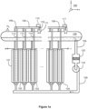
Figures 1a and1b illustrate a system according to an exemplifying and non-limiting embodiment for alkaline water electrolysis. Viewing directions related tofigures 1a and1b are expressed with the aid of acoordinate system 199. The system comprises a stack of electrolysis cells each of which contains alkaline liquid electrolyte. Infigure 1a , four of the electrolysis cells are denoted withreferences figures 1a and1b , the electrolysis cells are electrically series connected. It is however also possible that electrolytic cells of a system according to an exemplifying and non-limiting embodiment are electrically parallel connected, or the electrolytic cells are arranged to constitute series connected groups of parallel connected electrolytic cells, or parallel connected groups of series connected electrolytic cells, or the electrolytic cells are electrically connected to each other in some other way. - The system comprises a
hydrogen separator tank 105 and afirst piping 106 from the cathode compartments of the electrolysis cells to an upper portion of thehydrogen separator tank 105. The system comprises an oxygen separator tank and asecond piping 108 from the anode compartments of the electrolysis cells to an upper portion of the oxygen separator tank. Infigure 1b , the oxygen separator tank is denoted with areference 107. The system comprises athird piping 109 for circulating the liquid electrolyte from a lower portion of thehydrogen separator tank 105 and from a lower portion of theoxygen separator tank 107 back to the electrolysis cells. In the hydrogen andoxygen separator tanks - In the exemplifying system illustrated in
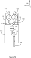
figures 1a and1b , thethird piping 109 comprises acontrollable pump 119 for pumping the liquid electrolyte to the electrolysis cells. A pump-controlled electrolyte cycle is advantageous especially when temperature control is needed. It is however also possible that a system according to an exemplifying and non-limiting embodiment comprises a gravitational electrolyte circulation. In the exemplifying system illustrated infigures 1a and1b , thethird piping 109 further comprises afilter 120 for filtering the liquid electrolyte. Thefilter 120 can be for example a membrane filter for removing impurities from the liquid electrolyte. - The hydrogen production rate dnH2/dt, mol s-1, of each electrolytic cell of the above-described system is linearly proportional to the electric current Icell as follows:

- In order to maximize the energy efficiency of an alkaline water electrolysis process, the above-mentioned Faraday efficiency ηF i.e. the ratio of the ideal hydrogen production rate to an actual hydrogen production rate should be as close to one as possible at all operating conditions. The Faraday efficiency decreases due to crossover of hydrogen gas to the anode compartments, i.e. to the oxygen side. Furthermore, the Faraday efficiency is reduced by stray currents taking place in the system for alkaline water electrolysis.
- The system comprises an
ultrasound source 110 attached to thefirst piping 106 and configured to apply ultrasound on the liquid electrolyte contained by thefirst piping 106. The frequency of the ultrasound can be for example in the range from 16 kHz to 200 kHz. The ultrasound enhances the separation of dissolved hydrogen gas H2 from the liquid electrolyte contained by the above-mentionedfirst piping 106. Therefore, the crossover of the hydrogen gas to the oxygen side is reduced. As a corollary, the Faraday efficiency of the system is improved. Furthermore, the safe control range of the system is broadened because the reduction in the hydrogen gas crossover reduces the amount of hydrogen gas on the oxygen side and thereby reduces a lower limit of the electric current and increases an upper limit of the operating pressure which correspond to a maximum allowable hydrogen content on the oxygen side. - In the exemplifying system illustrated in
figures 1a and1b , theultrasound source 110 comprises anultrasound radiator 118 that is inside thefirst piping 106. It is also possible that an ultrasound radiator is attached to an outer wall of thefirst piping 106, or there is some other arrangement for conducting ultrasound waves to the liquid electrolyte contained by thefirst piping 106. - In the exemplifying system illustrated in
figures 1a and1b , the first piping is arranged form manifolds each of which comprises a collector pipe connected to thehydrogen separator tank 105 and branch pipes connected to the collector pipe and to the cathode compartments of three of the electrolysis cells. The system comprises one ultrasound source per each manifold so that the ultrasound source related to a manifold under consideration is attached to the collector pipe of the manifold. In the exemplifying case illustrated infigures 1a and1b , the cathode compartments of the electrolysis cells 101-103 are connected to thehydrogen separator tank 105 with a manifold that comprises thebranch pipes ultrasound source 110 is attached to the collector pipe 111. Correspondingly, the cathode compartments of three other electrolysis cells, including theelectrolysis cell 104, are connected to thehydrogen separator tank 105 with another manifold, and anultrasound source 117 is attached to the collector pipe of this manifold. It is to be noted that the above-described mechanical arrangement of the first piping is a non-limiting example only, many different mechanical arrangements of the first piping being possible in systems according to exemplifying and non-limiting embodiments. - In the exemplifying system illustrated in
figures 1a and1b , thesecond piping 108 from the anode compartments of the electrolysis cells to the oxygen separator tank is provided with ultrasound sources in the same way as the first piping from the cathode compartments of the electrolysis cells to thehydrogen separator tank 105. - In
figure 1b , one of the ultrasound sources attached to thesecond piping 108 is denoted with areference 122. The ultrasound sources attached to thesecond piping 108 enhance the separation of dissolved oxygen gas from the liquid electrolyte contained by thesecond piping 108. Therefore, crossover of the oxygen gas to the hydrogen side is reduced. It is however also possible that a system according to an exemplifying and non-limiting embodiment comprises one or more ultrasound sources on the hydrogen side only. -
Figure 2 shows a flowchart of a method according to an exemplifying and non-limiting embodiment for alkaline water electrolysis. The method comprises the following actions: - action 201: conducting electric current to electrolysis cells each comprising an anode, a cathode, and a porous diaphragm dividing the electrolysis cell into a cathode compartment containing the cathode and an anode compartment containing the anode, and
- action 202: applying ultrasound on liquid electrolyte contained by a first piping conducting hydrogen gas and the liquid electrolyte from the cathode compartments of the electrolysis cells to an upper portion of a hydrogen separator tank so as to separate dissolved hydrogen gas from the liquid electrolyte contained by the first piping.
- In a method according to an exemplifying and non-limiting embodiment, the above-mentioned first piping forms a manifold comprising a collector pipe connected to the hydrogen separator tank and branch pipes connected to the collector pipe and to the cathode compartments of two or more of the electrolysis cells, and the ultrasound is applied on the liquid electrolyte contained by the collector pipe.
- In a method according to an exemplifying and non-limiting embodiment, the above-mentioned first piping forms at least one other manifold comprising another collector pipe connected to the hydrogen separator tank and other branch pipes connected to the other collector pipe and to the cathode compartments of other two or more of the electrolysis cells. In this exemplifying case, the method comprises applying ultrasound also on the liquid electrolyte contained by the other collector pipe.
- A method according to an exemplifying and non-limiting embodiment comprises applying ultrasound on the liquid electrolyte contained by a second piping conducting oxygen gas and the liquid electrolyte from the anode compartments of the electrolysis cells to an upper portion of an oxygen separator tank so as to separate dissolved oxygen gas from the liquid electrolyte contained by the second piping.
- In a method according to an exemplifying and non-limiting embodiment, the liquid electrolyte comprises aqueous potassium hydroxide "KOH".
- In a method according to an exemplifying and non-limiting embodiment, the liquid electrolyte comprises aqueous sodium hydroxide "NaOH".
- The specific examples provided in the description given above should not be construed as limiting the applicability and/or the interpretation of the appended claims. Lists and groups of examples provided in the description given above are not exhaustive unless otherwise explicitly stated.
Claims (15)
- A system for alkaline water electrolysis, the system comprising:- one or more electrolysis cells (101-104) each comprising an anode, a cathode, and a porous diaphragm dividing the electrolysis cell into a cathode compartment containing the cathode and an anode compartment containing the anode,- a hydrogen separator tank (105) and a first piping (106) from the cathode compartments of the electrolysis cells to an upper portion of the hydrogen separator tank,- an oxygen separator tank (107) and a second piping (108) from the anode compartments of the electrolysis cells to an upper portion of the oxygen separator tank, and- a third piping (109) for conducting liquid electrolyte from a lower portion of the hydrogen separator tank and from a lower portion of the oxygen separator tank to the electrolysis cells,characterized in that the system comprises an ultrasound source (110) attached to the first piping and for applying ultrasound on the liquid electrolyte contained by the first piping to separate dissolved hydrogen gas from the liquid electrolyte contained by the first piping.
- A system according to claim 1, wherein the first piping is arranged to form a manifold comprising a collector pipe (111) connected to the hydrogen separator tank and branch pipes (112-114) connected to the collector pipe and to the cathode compartments of two or more of the electrolysis cells, the ultrasound source being attached to the collector pipe.
- A system according to claim 2, wherein the first piping is arranged to form at least one other manifold comprising another collector pipe connected to the hydrogen separator tank and other branch pipes connected to the other collector pipe and to the cathode compartments of other two or more of the electrolysis cells, and the system further comprises at least one other ultrasound source (117) attached to the other collector pipe.
- A system according to any one of claims 1-3, wherein the ultrasound source comprises an ultrasound radiator (118) inside the first piping.
- A system according to any one of claims 1-4, wherein the third piping comprises a controllable pump (119) for pumping the liquid electrolyte to the electrolysis cells.
- A system according to any one of claims 1-5, wherein the third piping comprises a filter (120) for filtering the liquid electrolyte.
- A system according to any one of claims 1-6, wherein the electrolysis cells (101-104) are electrically series connected.
- A system according to any one of claims 1-6, wherein the electrolysis cells are electrically parallel connected.
- A system according to any one of claims 1-8, wherein the system comprises an ultrasound source (122) attached to the second piping (108) and for applying ultrasound on the liquid electrolyte contained by the second piping to separate dissolved oxygen gas from the liquid electrolyte contained by the second piping.
- A method for alkaline water electrolysis, the method comprising conducting (201) electric current to electrolysis cells each comprising an anode, a cathode, and a porous diaphragm dividing the electrolysis cell into a cathode compartment containing the cathode and an anode compartment containing the anode, characterized in that the method comprises applying (202) ultrasound on liquid electrolyte contained by a first piping conducting hydrogen gas and the liquid electrolyte from the cathode compartments of the electrolysis cells to an upper portion of a hydrogen separator tank so as to separate dissolved hydrogen gas from the liquid electrolyte contained by the first piping.
- A method according to claim 10, wherein the first piping forms a manifold comprising a collector pipe connected to the hydrogen separator tank and branch pipes connected to the collector pipe and to the cathode compartments of two or more of the electrolysis cells, the ultrasound being applied on the liquid electrolyte contained by the collector pipe.
- A method according to claim 11, wherein the first piping forms at least one other manifold comprising another collector pipe connected to the hydrogen separator tank and other branch pipes connected to the other collector pipe and to the cathode compartments of other two or more of the electrolysis cells, and the method comprises applying ultrasound on the liquid electrolyte contained by the other collector pipe.
- A method according to any one of claims 10-12, wherein the method comprises applying ultrasound on the liquid electrolyte contained by a second piping conducting oxygen gas and the liquid electrolyte from the anode compartments of the electrolysis cells to an upper portion of an oxygen separator tank so as to separate dissolved oxygen gas from the liquid electrolyte contained by the second piping.
- A method according to any one of claims 10-13, wherein the liquid electrolyte comprises aqueous potassium hydroxide.
- A method according to any one of claims 10-13, wherein the liquid electrolyte comprises aqueous sodium hydroxide.
Applications Claiming Priority (2)
| Application Number | Priority Date | Filing Date | Title |
|---|---|---|---|
| FI20195758A FI128890B (en) | 2019-09-12 | 2019-09-12 | A system and a method for alkaline water electrolysis |
| PCT/FI2020/050446 WO2021048461A1 (en) | 2019-09-12 | 2020-06-23 | A system and a method for alkaline water electrolysis |
Publications (3)
| Publication Number | Publication Date |
|---|---|
| EP4028355A1 EP4028355A1 (en) | 2022-07-20 |
| EP4028355B1 true EP4028355B1 (en) | 2023-09-13 |
| EP4028355C0 EP4028355C0 (en) | 2023-09-13 |
Family
ID=71614915
Family Applications (1)
| Application Number | Title | Priority Date | Filing Date |
|---|---|---|---|
| EP20740357.7A Active EP4028355B1 (en) | 2019-09-12 | 2020-06-23 | A system and a method for alkaline water electrolysis |
Country Status (4)
| Country | Link |
|---|---|
| US (1) | US20220325425A1 (en) |
| EP (1) | EP4028355B1 (en) |
| FI (1) | FI128890B (en) |
| WO (1) | WO2021048461A1 (en) |
Families Citing this family (2)
| Publication number | Priority date | Publication date | Assignee | Title |
|---|---|---|---|---|
| KR20210103780A (en) * | 2020-02-14 | 2021-08-24 | 현대자동차주식회사 | Hydroelectric system and control method of the same |
| EP4339327A1 (en) * | 2022-09-14 | 2024-03-20 | Linde GmbH | Method for operating an electrolysis system, and electrolysis system |
Citations (1)
| Publication number | Priority date | Publication date | Assignee | Title |
|---|---|---|---|---|
| JP2011006769A (en) * | 2009-06-29 | 2011-01-13 | Mitsubishi Heavy Ind Ltd | Water electrolysis apparatus |
Family Cites Families (7)
| Publication number | Priority date | Publication date | Assignee | Title |
|---|---|---|---|---|
| US7559978B2 (en) * | 2005-09-19 | 2009-07-14 | General Electric Company | Gas-liquid separator and method of operation |
| US20120063967A1 (en) * | 2009-05-21 | 2012-03-15 | Panasonic Corporation | Hydrogen generation system and hot water production system |
| CA2860419C (en) * | 2011-01-12 | 2020-12-15 | Ceramatec, Inc. | Electrochemical production of hydrogen |
| JP2015000354A (en) * | 2013-06-13 | 2015-01-05 | シャープ株式会社 | Hydrogen-dissolved water generator |
| JP6697333B2 (en) * | 2016-06-29 | 2020-05-20 | マクセルホールディングス株式会社 | Electrolytic hydrogen water producing method and electrolytic hydrogen water producing apparatus |
| KR101732659B1 (en) * | 2016-10-17 | 2017-05-24 | 한동하이드로 주식회사 | Functional water producing device using reversible polymer electrolyte membrane fuel cell |
| CN108862533A (en) * | 2018-06-21 | 2018-11-23 | 鲁言和 | A kind of hydrogen beverage dispenser |
-
2019
- 2019-09-12 FI FI20195758A patent/FI128890B/en active IP Right Grant
-
2020
- 2020-06-23 WO PCT/FI2020/050446 patent/WO2021048461A1/en unknown
- 2020-06-23 US US17/642,558 patent/US20220325425A1/en active Pending
- 2020-06-23 EP EP20740357.7A patent/EP4028355B1/en active Active
Patent Citations (1)
| Publication number | Priority date | Publication date | Assignee | Title |
|---|---|---|---|---|
| JP2011006769A (en) * | 2009-06-29 | 2011-01-13 | Mitsubishi Heavy Ind Ltd | Water electrolysis apparatus |
Also Published As
| Publication number | Publication date |
|---|---|
| FI20195758A1 (en) | 2021-02-26 |
| EP4028355A1 (en) | 2022-07-20 |
| FI128890B (en) | 2021-02-26 |
| US20220325425A1 (en) | 2022-10-13 |
| WO2021048461A1 (en) | 2021-03-18 |
| EP4028355C0 (en) | 2023-09-13 |
Similar Documents
| Publication | Publication Date | Title |
|---|---|---|
| US4758322A (en) | Apparatus for the electrolysis of solutions | |
| US20180371630A1 (en) | High pressure electrochemical cell | |
| EP4028355B1 (en) | A system and a method for alkaline water electrolysis | |
| HU183256B (en) | Bipolar diaphragm electrolyzer and bipolar cell | |
| EP3312304B1 (en) | Water treatment system using alkaline water electrolysis device and alkaline fuel cell | |
| CN102597326A (en) | Proton exchange membrane water electrolyser cell module design | |
| US6849356B2 (en) | Separated flow liquid catholyte aluminum hydrogen peroxide seawater semi fuel cell | |
| KR20180126573A (en) | Water electrolytic device | |
| MX2014015248A (en) | Gas permeable electrodes and electrochemical cells. | |
| US20160312370A1 (en) | Electrochemical cell without an electrolyte-impermeable barrier | |
| CN113403630A (en) | Hydrogen producing device by catalytic electrolysis | |
| JP2011162864A (en) | Water electrolysis system and method of stopping the same | |
| JPWO2018139613A1 (en) | Bipolar element, Bipolar electrolytic cell, Hydrogen production method | |
| WO2020162772A1 (en) | Electrolyzer for hydrogen and oxygen production | |
| JP5341547B2 (en) | Water electrolysis system | |
| JP2009138253A (en) | Electrolyzer and fuel cell power generation system using the same | |
| AU2021279136B2 (en) | Electrolytic cell, method for operating a cell of this type and electrolyser | |
| CN115821300A (en) | Electrolytic cell device for water electrolysis hydrogen production by proton exchange membrane | |
| US20220290319A1 (en) | Cross-flow water electrolysis | |
| SE447583B (en) | BIPOLER ELECTROLYSOR | |
| CN111826671A (en) | Device and method for producing gas by electrolyzing water | |
| Hartvigsen et al. | New low to medium temperature electrolyte separation method and system for alkaline water electrolysis | |
| JP2011208163A (en) | Water electrolyzer | |
| JP2013036068A (en) | High-pressure water electrolytic system and method for operating the same | |
| US20230387511A1 (en) | Sheet-shaped anode fed-type metal-carbon dioxide battery and hydrogen generation and carbon dioxide storage system including the same |
Legal Events
| Date | Code | Title | Description |
|---|---|---|---|
| STAA | Information on the status of an ep patent application or granted ep patent |
Free format text: STATUS: UNKNOWN |
|
| STAA | Information on the status of an ep patent application or granted ep patent |
Free format text: STATUS: THE INTERNATIONAL PUBLICATION HAS BEEN MADE |
|
| PUAI | Public reference made under article 153(3) epc to a published international application that has entered the european phase |
Free format text: ORIGINAL CODE: 0009012 |
|
| STAA | Information on the status of an ep patent application or granted ep patent |
Free format text: STATUS: REQUEST FOR EXAMINATION WAS MADE |
|
| 17P | Request for examination filed |
Effective date: 20220302 |
|
| AK | Designated contracting states |
Kind code of ref document: A1 Designated state(s): AL AT BE BG CH CY CZ DE DK EE ES FI FR GB GR HR HU IE IS IT LI LT LU LV MC MK MT NL NO PL PT RO RS SE SI SK SM TR |
|
| DAV | Request for validation of the european patent (deleted) | ||
| DAX | Request for extension of the european patent (deleted) | ||
| REG | Reference to a national code |
Ref legal event code: R079 Ref document number: 602020017667 Country of ref document: DE Free format text: PREVIOUS MAIN CLASS: C01B0013140000 Ipc: C25B0001040000 Ref country code: DE |
|
| GRAP | Despatch of communication of intention to grant a patent |
Free format text: ORIGINAL CODE: EPIDOSNIGR1 |
|
| STAA | Information on the status of an ep patent application or granted ep patent |
Free format text: STATUS: GRANT OF PATENT IS INTENDED |
|
| RIC1 | Information provided on ipc code assigned before grant |
Ipc: C25B 15/08 20060101ALI20230320BHEP Ipc: C25B 9/77 20210101ALI20230320BHEP Ipc: C25B 9/73 20210101ALI20230320BHEP Ipc: C25B 9/23 20210101ALI20230320BHEP Ipc: C25B 1/04 20210101AFI20230320BHEP |
|
| INTG | Intention to grant announced |
Effective date: 20230413 |
|
| GRAS | Grant fee paid |
Free format text: ORIGINAL CODE: EPIDOSNIGR3 |
|
| GRAA | (expected) grant |
Free format text: ORIGINAL CODE: 0009210 |
|
| STAA | Information on the status of an ep patent application or granted ep patent |
Free format text: STATUS: THE PATENT HAS BEEN GRANTED |
|
| AK | Designated contracting states |
Kind code of ref document: B1 Designated state(s): AL AT BE BG CH CY CZ DE DK EE ES FI FR GB GR HR HU IE IS IT LI LT LU LV MC MK MT NL NO PL PT RO RS SE SI SK SM TR |
|
| REG | Reference to a national code |
Ref country code: CH Ref legal event code: EP |
|
| REG | Reference to a national code |
Ref country code: DE Ref legal event code: R096 Ref document number: 602020017667 Country of ref document: DE |
|
| REG | Reference to a national code |
Ref country code: IE Ref legal event code: FG4D |
|
| U01 | Request for unitary effect filed |
Effective date: 20230913 |
|
| U07 | Unitary effect registered |
Designated state(s): AT BE BG DE DK EE FI FR IT LT LU LV MT NL PT SE SI Effective date: 20230920 |
|
| PG25 | Lapsed in a contracting state [announced via postgrant information from national office to epo] |
Ref country code: GR Free format text: LAPSE BECAUSE OF FAILURE TO SUBMIT A TRANSLATION OF THE DESCRIPTION OR TO PAY THE FEE WITHIN THE PRESCRIBED TIME-LIMIT Effective date: 20231214 |
|
| PG25 | Lapsed in a contracting state [announced via postgrant information from national office to epo] |
Ref country code: RS Free format text: LAPSE BECAUSE OF FAILURE TO SUBMIT A TRANSLATION OF THE DESCRIPTION OR TO PAY THE FEE WITHIN THE PRESCRIBED TIME-LIMIT Effective date: 20230913 Ref country code: NO Free format text: LAPSE BECAUSE OF FAILURE TO SUBMIT A TRANSLATION OF THE DESCRIPTION OR TO PAY THE FEE WITHIN THE PRESCRIBED TIME-LIMIT Effective date: 20231213 Ref country code: HR Free format text: LAPSE BECAUSE OF FAILURE TO SUBMIT A TRANSLATION OF THE DESCRIPTION OR TO PAY THE FEE WITHIN THE PRESCRIBED TIME-LIMIT Effective date: 20230913 Ref country code: GR Free format text: LAPSE BECAUSE OF FAILURE TO SUBMIT A TRANSLATION OF THE DESCRIPTION OR TO PAY THE FEE WITHIN THE PRESCRIBED TIME-LIMIT Effective date: 20231214 |
|
| PG25 | Lapsed in a contracting state [announced via postgrant information from national office to epo] |
Ref country code: IS Free format text: LAPSE BECAUSE OF FAILURE TO SUBMIT A TRANSLATION OF THE DESCRIPTION OR TO PAY THE FEE WITHIN THE PRESCRIBED TIME-LIMIT Effective date: 20240113 |