EP4027763A1 - Component holding apparatus - Google Patents
Component holding apparatus Download PDFInfo
- Publication number
- EP4027763A1 EP4027763A1 EP19943931.6A EP19943931A EP4027763A1 EP 4027763 A1 EP4027763 A1 EP 4027763A1 EP 19943931 A EP19943931 A EP 19943931A EP 4027763 A1 EP4027763 A1 EP 4027763A1
- Authority
- EP
- European Patent Office
- Prior art keywords
- component
- components
- holding
- inputted
- stage
- Prior art date
- Legal status (The legal status is an assumption and is not a legal conclusion. Google has not performed a legal analysis and makes no representation as to the accuracy of the status listed.)
- Granted
Links
Images









Classifications
-
- H—ELECTRICITY
- H05—ELECTRIC TECHNIQUES NOT OTHERWISE PROVIDED FOR
- H05K—PRINTED CIRCUITS; CASINGS OR CONSTRUCTIONAL DETAILS OF ELECTRIC APPARATUS; MANUFACTURE OF ASSEMBLAGES OF ELECTRICAL COMPONENTS
- H05K13/00—Apparatus or processes specially adapted for manufacturing or adjusting assemblages of electric components
- H05K13/04—Mounting of components, e.g. of leadless components
- H05K13/0404—Pick-and-place heads or apparatus, e.g. with jaws
- H05K13/0408—Incorporating a pick-up tool
-
- H—ELECTRICITY
- H05—ELECTRIC TECHNIQUES NOT OTHERWISE PROVIDED FOR
- H05K—PRINTED CIRCUITS; CASINGS OR CONSTRUCTIONAL DETAILS OF ELECTRIC APPARATUS; MANUFACTURE OF ASSEMBLAGES OF ELECTRICAL COMPONENTS
- H05K13/00—Apparatus or processes specially adapted for manufacturing or adjusting assemblages of electric components
- H05K13/08—Monitoring manufacture of assemblages
- H05K13/081—Integration of optical monitoring devices in assembly lines; Processes using optical monitoring devices specially adapted for controlling devices or machines in assembly lines
- H05K13/0813—Controlling of single components prior to mounting, e.g. orientation, component geometry
Definitions
- the present invention relates to a component holding apparatus for holding a component on a stage on which components are scattered to pick it up therefrom.
- a technical problem to be solved by the present invention is how to suitably hold a component on a stage on which components are scattered to pick it up therefrom.
- a component holding apparatus including a stage on which components of one type are scattered, and an imaging device configured to image the components of one type which are scattered on the stage, wherein the components of one type which are scattered on the stage are held based on inputted multiple heights of the components of one type and image data captured by the imaging device.
- the components of one type which are scattered on the stage, are held based on the inputted multiple heights of the components of one type and the image data captured by the imaging device.
- the components can suitably be held to be picked up from the stage on which the components are scattered.
- work heads 60, 62 are detachably positioned on sliders 74, 76, respectively, through a one-touch action by an operator without using any tool to thereby be detachably attached thereto, and Z-direction moving device 72 moves sliders 74, 76 in an up-down direction individually and separately. That is, work heads 60, 62 are moved in the up-down direction individually and separately by Z-direction moving device 72.
- Imaging device 26 is attached to slider 74 in such a state that imaging device 26 is directed downwards and is moved in the X-direction, Y-direction, and Z-direction together with work head 60. As a result, imaging device 26 images any position on frame 40. As shown in Fig. 1 , imaging device 28 is disposed between base material conveyance and holding device 22 on frame 40 and component supply device 30 in such a state that imaging device 28 is directed upwards. As a result, imaging device 28 images components held by suction nozzles 66 of work heads 60, 62.
- Component supply device 30 is disposed at a first end portion of component mounting device 24 in a front-rear direction of frame 40.
- Component supply device 30 includes tray-type component supply device 78 and a feeder-type component supply device (not shown).
- Tray-type component supply device 78 is a device for supplying components in such a state that the components are placed on a tray.
- Feeder-type component supply device is a device for supplying components by a tape feeder (not shown), a stick feeder (not shown), a bulk component feeder device for supplying multiple components which are scattered separately, or the like.
- bulk component supply device 32 includes main body 80, component supply units 82, two-dimensional imaging device 84, and component delivery device 86.
- component feeder 88 has a generally rectangular parallelepiped box-like shape and is disposed in such a manner as to extend in the Y direction.
- the Y-direction will be described as a front-rear direction of component feeder 88, a direction toward an end of component supply unit 82 where component return device 92 is disposed will be described as front or forward, and a direction toward an end of component supply unit 82 where component feeder 88 is disposed will be described as rear or rearward.
- Component feeder 88 is opened in an upper surface and a front surface thereof, and an opening in the upper surface is made into component loading port 97, while an opening in the front surface is made into component discharge port 98.
- inclined plate 104 is disposed below loading port 97. Inclined plate 104 is disposed in such a manner as to be inclined downward in a direction toward a center of component feeder 88 from a rear end face thereof.
- conveyor device 106 is disposed at the front of inclined plate 104, as shown in Fig. 5 .
- Conveyor device 106 is disposed in such a manner as to be inclined upward from a front end portion of inclined plate 104 toward the front of component feeder 88.
- Conveyor belt 112 of conveyor device 106 is caused to rotate in a counterclockwise direction in Fig. 5 by driving electromagnetic motor (refer to Fig. 12 ) 116. That is, a conveyance direction of conveyor device 106 is referred to as an obliquely upward direction extending forwards from the front end portion of inclined plate 104 .
- inclined plate 126 is disposed below a front end portion of conveyor device 106.
- Inclined plate 126 is disposed in such a manner as to extend from a front end face of component feeder 88 towards below conveyor device 106, and a rear end portion of inclined plate 126 is inclined obliquely downward.
- inclined plate 128 is also disposed below inclined plate 126. Inclined plate 128 is disposed to extend from a position lying below a center portion of conveyor device 106 towards discharge port 98 of component feeder 88 in such a manner as to be inclined so that a front end portion of inclined plate 128 is positioned further downward.
- frame 89 is made up of pair of side frames 130 and connecting frame 132. Pair of side frames 130 are erected in such a manner as to extend parallel to each other and in the Y-direction while facing each other. Then, connecting frame 132 is placed at lower ends of pair of side frames 130 in such a manner as to straddle a space defined therebetween, whereby pair of side frames 130 are connected together by connecting frame 132.
- Frame 89 functions as a housing of component supply unit 82; however, frame 89 may not function as a housing but may constitute a reinforcing member, an outer shell member, a housing, a cover, a casing, or the like of component supply unit 82.
- a distance between pair of side frames 130 is set slightly larger than a widthwise dimension of component feeder 88, so that component feeder 88 can detachably be mounted between pair of side frames 130 through a one-touch action while being positioned therebetween.
- Detachable mounting through the one-touch action means that component feeder 88 is detachably mounted in position in a repeatable fashion by the operator without using any tool or the like.
- component scattering device 90 includes component support member 150 and component support member moving device 152.
- Component support member 150 is made up of stage 156 and pair of side wall portions 158.
- Stage 156 has a generally longitudinal plate-like shape and is disposed in such a manner as to extend to the front from below component feeder 88 mounted between pair of side frames 130. Additionally, a widthwise dimension of stage 156 is set approximately the same as the distance defined between pair of side frames 130, that is, a widthwise dimension of frame 89, and a rear end portion of stage 156 is positioned between pair of side frames 130.
- stage 156 An upper surface of stage 156 is generally horizontal and is disposed in such a state that a slight clearance is provided between a front end portion of inclined plate 128 of component feeder 88 and itself at a rear end portion thereof as shown in Fig. 5 . Further, as shown in Fig. 4 , pair of side wall portions 158 are individually erected along both longitudinal side portions of stage 156 in such a manner as to be fixed thereto, and upper ends of both side wall portions 158 extend further upwards than the upper surface of stage 156.
- Component support member moving device 152 causes component support member 150 to slide in the Y-direction as air cylinder (refer to Fig. 12 ) 166 operates accordingly. As this occurs, component support member 150 moves between a retracted state (refer to Fig. 6 ) in which component support member 150 is retracted underneath component feeder 88 and an exposed state (refer to Fig. 5 ) in which component support member 150 is exposed from underneath component feeder 88.
- component return device 92 includes component accommodating container 180 and container swing device 181.
- Component accommodating container 180 has a generally box-like shape and an arc-shaped bottom surface.
- a widthwise dimension of component accommodating container 180 is set approximately the same as the widthwise dimension of stage 156. That component accommodating container 180 is held in a swinging fashion at a front end portion of stage 156 and swings as container swing device 181 operates accordingly.
- component accommodating container 180 swings between an accommodation orientation (refer to Fig. 8 ) in which an opening thereof is directed upwards and a return orientation (refer to Fig. 9 ) in which the opening is directed towards the upper surface of stage 156 of component support member 150.
- two-dimensional imaging device 84 includes camera 290 and camera moving device 292.
- Camera moving device 292 includes guide rail 296 and slider 298.
- Guide rail 296 is fixed to main body 80 above component feeders 88 in such a manner as to extend in a widthwise direction (X-direction) of bulk component supply device 32.
- Slider 298 is slidably attached to guide rail 296 and slides to any position as electromagnetic motor (refer to Fig. 12 ) 299 operates accordingly.
- Cameras 290 is provided one and is fixedly attached to slider 298 in such a state that camera 29 is directed downwards.
- Camera 290 is a three-dimensional camera which can detect height information, depth information, or the like of a three-dimensional imaging target object or a two-dimensional camera without a three-dimensional image processing device which cannot detect height information, depth information, or the like of a three-dimensional imaging target object.
- camera 290 does not employ a telecentric lens system in which an aperture stop is located in a focal point position of a lens but employs a general lens, that is, a lens whose angle of view is not 0 degree.
- Component delivery device 86 includes, as shown in Fig. 3 , component holding head moving device 300, component holding head 302, and two shuttle devices 304.
- Component holding head moving device 300 includes X-direction moving device 310, Y-direction moving device 312, and Z-direction moving device 314.
- Y-direction moving device 312 includes Y-slider 316 which is disposed above component supply units 82 in such a manner as to extend in the X-direction, and Y-slider 316 moves to any position in the Y-direction as electromagnetic motor (refer to Fig. 12 ) 319 is driven accordingly.
- X-direction moving device 310 includes X-slider 320 which is disposed on a side surface of Y-slider 316, and X-slider 320 moves to any position in the X-direction as electromagnetic motor (refer to Fig.
- Z-direction moving device 314 includes Z-slider 322 which is disposed on a side surface of X-slider 320, and Z-slider 322 moves to any position in the Z-direction as electromagnetic motor (refer to Fig. 12 ) 323 is driven accordingly.
- component holding head 302 includes head main body 330, suction nozzle 332, nozzle pivoting device 334, and nozzle rotation device 335.
- Head main body 330 is formed integrally with Z-slider 322.
- Suction nozzle 332 is configured to hold a component and is detachably attached to a lower end portion of holder 340.
- Holder 340 is configured to be bendable on support shaft 344, and holder 340 is bent upwards through 90 degrees as nozzle pivoting device 334 operates accordingly.
- suction nozzle 332 which is attached to the lower end portion of holder 340, pivots through 90° to be positioned in a pivoted position and then stops there.
- suction nozzle 332 pivots between a non-pivoted position and the pivoted position as nozzle pivoting device 334 operates accordingly.
- suction nozzle 332 can be positioned to stop at an angle position between the non-pivoted position and the pivoted position.
- Nozzle rotation device 335 causes suction nozzle 332 to rotate around an axis center thereof.
- two shuttle devices 304 each include component carrier 388 and component carrier moving device 390 and are fixed to main body 80 in such a manner as to be aligned side by side in a lateral direction along front ends of component supply units 82.
- Component carrier 388 includes five component receiving members 392, which are attached thereto while being aligned in a row in the lateral direction, so that components are placed individually and separately on component receiving members 392.
- Component receiving member 392 has formed therein component receiving recessed section 416 having a shape matching the shape of lead component 410.
- Component receiving recessed section 416 is a recessed section having a stepped shape and is made up of main body section receiving recessed section 418, which opens in an upper surface of component receiving member 392, and lead receiving recessed section 420, which is formed to provide an opening in a bottom surface of main body section receiving recessed section 418.
- lead component 410 is inserted inside component receiving recessed section 416 while being oriented in such a manner that leads 414 are directed downwards.
- lead component 410 is placed inside component receiving recessed section 416 in such a state that leads 414 are inserted into lead receiving recessed section 420 and component main body 412 is inserted into main body section receiving recessed section 418.
- component carrier moving device 390 is a plate-shaped longitudinal member and is disposed at the front ends of component supply units 82 in such a manner as to extend in the front-rear direction.
- Component carrier 388 is disposed on an upper surface of component carrier moving device 390 in such a manner as to slide in the front-rear direction, so that component carrier 388 slides to an arbitrary position in the front-rear direction as electromagnetic motor (refer to Fig. 12 ) 430 is driven accordingly.
- electromagnetic motor (refer to Fig. 12 ) 430 is driven accordingly.
- control devices 452 are each made up mainly of a computer and are provided individually and separately for base material conveyance and holding device 22, component mounting device 24, imaging device 26, imaging device 28, component supply device 30, and bulk component supply device 32 (in the figure, only individual control device 452 for bulk component supply device 32 is shown).
- Individual control device 452 of bulk component supply device 32 is connected to component feeder 88, component scattering device 90, component return device 92, camera moving device 292, component holding head moving device 300, component holding head 302, and shuttle devices 304.
- individual control device 452 of bulk component supply device 32 controls component feeder 88, component scattering device 90, component return device 92, camera moving device 292, component holding head moving device 300, component holding head 302, and shuttle devices 304.
- Image processing device 454 is connected to two-dimensional imaging device 84 to process image data captured by two-dimensional imaging device 84. That image processing device 454 is connected to individual control device 452 of bulk component supply device 32.
- individual control device 452 of bulk component supply device 32 obtains two-dimensional image data captured by two-dimensional imaging device 84.
- component mounter 10 executes a component mounting operation on circuit base material 12 which is held by base material conveyance and holding device 22.
- circuit base material 12 is conveyed to a work position by base material conveyance and holding device 22 and is fixedly held by clamp device 52 in that work position.
- imaging device 26 moves to a position lying above circuit base material 12, which is now fixedly held in position, and images circuit base material 12.
- Component supply device 30 or bulk component supply device 32 supplies a component in a predetermined supply position. A supply of a component by bulk component supply device 32 will be described in detail later on.
- components 410 of one type are loaded into loading port 97 of one component feeder 88 by the operator, and these lead components 410 so loaded are supplied in such a state that they are placed on component receiving member 392 of component carrier 388 as component supply unit 82 and component delivery device 86 operate accordingly.
- component support member 150 is caused to move to the position lying below component feeder 88 in question as a result of operation of component support member moving device 152 to thereby stay in the retracted state (refer to Fig. 6 ).
- component accommodating container 180 which is disposed at the front end portion of component support member 150, is positioned at the front of component feeder 88, assuming an orientation (an accommodating orientation) in which the opening of component accommodating container 180 is directed upwards.
- Lead components 410 loaded from loading port of inlet 97 of component feeder 88 fall on inclined plate 104 of component feeder 88 and roll down to a lower end of inclined plate 104 at the front thereof. Then, lead components 410, which have rolled down to the lower end at the front of inclined plate 104, are accumulated between the lower end of inclined plate 104 at the front thereof and a lower end of conveyor device 106 at the rear thereof. Then, conveyor belt 112 of conveyor device 106 circulates counterclockwise, as seen in Fig. 6 , as conveyor device 106 operates accordingly. As this occurs, lead components 410, which are accumulated between inclined plate 104 and conveyor belt 112, are then conveyed obliquely upwards by conveyor belt 112.
- Lead components 410 which are conveyed by conveyor belt 112, fall on inclined plate 126 from an upper end of conveyor device 106 at the front thereof. Lead components 410, which have fallen on inclined plate 126, then roll down on inclined plate 126 to the rear to fall onto inclined plate 128. Lead components 410,which have fallen on inclined plate 128, then roll down to the front to be discharged from discharge port 98 of component feeder 88 at the front thereof.
- container swinging device 181 of component return device 92 operates at a timing when component support member 150 moves a predetermined amount from the retracted state towards the front where component support member 150 is put in an exposed state, whereby component accommodating container 180 starts swinging.
- the orientation of component accommodating container 180 vigorously changes from the orientation(accommodating orientation) in which the opening is directed upwards to an orientation (returned orientation) in which the opening is directed towards stage 156.
- lead components 410 which are accommodated in component accommodating container 180, are vigorously discharged towards stage 156.
- lead components 410 of one type are scattered from component accommodating container 180 onto stage 156. In this case, for scattering of lead components 410, situations are considered in which lead components 410 are scattered while overlapping one another and in which lead components 410 are scattered separately from one another without overlapping one another.
- component holding head 302 is caused to move to a position lying above one lead component 410 based on the information on the position and orientation thereof so calculated and the like as component holding head moving device 300 operates accordingly, whereby lead component 410 in question is picked up and held by suction nozzle 332.
- suction nozzle 332 is positioned in the non-pivoted position with a suction port thereof directed downwards, and a pickup surface, which constitutes the suction port, stays parallel to a horizontal plane.
- component holding head 302 moves upwards away from component carrier 388 after lead component 410 is held by suction nozzle 332.
- component carrier 388 is then moved to the component receiving position as a result of operation of component carrier moving device 390.
- suction nozzle 332 is pivoted to the pivoted position.
- Suction nozzle 332 is caused to revolve by nozzle rotation device 335 which operates accordingly so that leads 414 of lead component 410 held by suction nozzle 332, which is now positioned in the pivoted position, are directed downwards in a vertical direction.
- lead component 410 When component holding head 302 moves upwards to stay above component carrier 388, lead component 410 whose leads 414 are directed downwards in the vertical direction are inserted into component receiving recessed section 416 of component receiving member 392. As a result, as shown in Fig. 11 , lead component 410 is placed in component receiving member 392 in such a state that leads 414 are directed downwards in the vertical direction.
- component carrier 388 moves to the component supply position as component carrier moving device 390 operates accordingly. Since component carrier 388, which has moved to the component supply position, is now positioned within the moving ranges of work heads 60, 62, in bulk component supply device 32, lead component 410 is supplied to component mounter 10 in this position. In this way, in bulk component supply device 32, lead component 410 is supplied while being placed in component receiving member 392 in such a state that leads 414 are directed downwards and the upper surface, which faces the bottom surface to which leads 414 are connected, is directed upwards. As a result, suction nozzles 66 of work heads 60, 62 can suitably hold corresponding lead components 410.
- components of one type are scattered from component feeder 88 onto stage 156, and the components so scattered on stage 156 are imaged by camera 290. Then, positions and orientations of those components are calculated based on the image data so captured, and the components scattered on stage 156 are held by component holding head 302 by making use of the positions and orientations so calculated.
- camera 290 used to image the components scattered on stage 156 is the two-dimensional camera, and further, no telecentric lens is used in camera 290. Therefore, when calculating positions and orientations of the components based on the image data so captured, positions and orientations of the components are calculated in consideration of a height dimension of the component.
- camera 290 when one component on stage 156 is imaged by camera 290, camera 290 performs fixed-point imaging. Specifically speaking, for example, camera 290 images the upper surface of stage 156 once in such a state that camera 290 is fixed at a center of stage 156 and at a predetermined height above stage 156.
- imaged component position a position of a component which is calculated based on image data captured for one of those scattered components
- actual component position a position where the component is actually placed
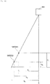
- component 500 having height dimension HR is placed in a position lying away from the origin, and in four corner portions of an upper end face of component 500 in question, one corner portion 502 is located a distance of X R away from the origin.
- corner portion 502 of component 500 is positioned a distance of Xo away from the origin. This is because corner portion 502 of component 500, which is located the distance of X R away from the origin, and an upper surface of stage 156 which is located the distance of Xo away from the origin are located on one principal ray 510 of camera 290.
- corner portion 502 of component 500 is calculated as being located the distance of Xo away from the origin.
- actual component position X R and imaged component position X O of corner portion 502 of component 500 differ from each other.
- an actual component position of corner portion 502 is calculated by making use of height dimension H R of component 500 and height dimension H O at which camera 290 is disposed. That is, the following expression is established between actual component position X R and imaged component position Xo.
- X 0 : X R H 0 : H 0 ⁇ H R
- corner portion 502 lies directly below camera 290, that is, at the origin (O)
- the actual component position and the imaged component position will coincide with each other, irrespective of the height dimension of the component.
- actual component position X R of corner portion 502 of component 500 is calculated in the way described above, actual component positions X R of three remaining corner portions 502 of component 500 are also calculated using the same method. Then, a holding position of component 500 is calculated based on actual component positions X R of the four corner portions of component 500. For example, in the case that a center of the upper end face of component 500 constitutes an expected holding position, a center position of actual component positions X R of the four corner portions is calculated as a component holding position.
- the component holding position calculated by the method described above is effective only in a case in which when the height dimension of the upper end face of the component is uniform, and hence, in the case that a height dimension of an upper end face of a component is not uniform, there may be a case in which a component holding position calculated deviates from an expected holding position of the component.
- a first surface of component 500 is made into a flat surface
- a second surface of component 500 is made into a stepped surface 521. That stepped surface 521 is made up of projecting section 522, which is located at a first end portion in a longitudinal direction, and recessed section 524, which is located at a second end portion in the longitudinal direction.
- a height dimension of projecting section 522 is referred to as H 1
- a height dimension of recessed section 524 is referred to as H 2 .
- component 520 has the two height dimensions (H 1 , H 2 ); however, since a component holding position is calculated using one height dimension in the method described above, a holding position of component 520 is experimentally calculated using, for example, the height dimension (Hi) of projecting section 522. Specifically speaking, in four corner portions 526, 528, 530, 532 of an upper end face of component 520, actual component positions of corner portions 526, 528 which are positioned on projecting section 522 are calculated using the height dimension (Hi). For this calculation, since the height dimension of corner portions 526, 528 is H 1 , actual component positions of corner portions 526, 528 can be calculated suitably by use of the height dimension (Hi).
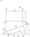
- components 520b, 520c deviate from a position lying directly below camera 290 on which an optical axis ray of camera 290 falls, and actual component positions of corner portions 530, 532 are calculated as being positioned X 1 , which is shorter than X 2 , away from the origin, although the actual component positions of corner portions 530, 532 are positioned X 2 away from the origin.
- calculated component holding positions (denoted by mark o) of components 520b, 520c deviate from expected holding positions (denoted by mark x), which are positions suitable for holding the components, towards positions lying closer to the position lying directly below camera 290, that is, closer to component 520a.
- a holding position of component 520 is experimentally calculated by use of, for example, the height dimension (H 2 ) of recessed section 524.
- H 2 the height dimension of recessed section 524.
- actual component positions of corner portions 530, 532 which are positioned on recessed section 524 are calculated by use of the height dimension (H 2 ).
- H 2 the height dimension of corner portions 530, 532
- actual component positions of corner portions 530, 532 can suitably be calculated by use of the height dimension (H 2 ).
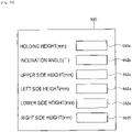
- Input box area 552a is a box area into which a holding height is inputted, and a holding height of a component at which the component is held by component holding head 302 is inputted.
- Input box area 552b is a box area into which an inclination angle of the holding surface is inputted, and an inclination angle of the holding surface resulting when component holding head 302 holds a component is inputted.
- 0 is inputted into input box area 552b.
- a center of flat surface 533 constitutes a holding position of component 520.
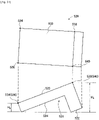
- a mean height dimension between the side including corner portion 534 and corner portion 536 and the side including corner portion 538 and corner portion 540, that is, height dimension (H 3 +H 4 )/2 is inputted into input box area 552a on input screen 550 as a holding height of component 520.
- height dimension H 8 of the side including corner portion 576 and corner portion 578 of flat surface 561 of component 560 which is oriented in such a manner that flat surface 561 is directed upwards is inputted into input box area 552c on input screen 550.
- height dimension H 9 of the side including corner portion 580 and corner portion 582 of flat surface 561 is inputted into input box area 552e.
- the height dimensions of the side including corner portion 576 and corner portion 580 and the side including corner portion 578 and corner portion 582 of flat surface 561 are inputted to input box area 552d and input box area 552f.
- the suction nozzle since the surface of the component which is directed upwards constitutes the holding surface in many cases, the height dimensions of the surface of the component which is directed upwards are inputted; however, in the case that a chuck is adopted as a component holding tool, since a surface of the component which is directed sideways constitutes the holding surface in many cases, the height dimensions of the surface of the component which is directed sideways may be inputted. However, not only the height dimensions of the holding surface but also height dimensions of one or more arbitrary surfaces of the multiple surfaces of the component can be inputted.
- the two-dimensional camera is adopted on which the lens which differs from a telecentric lens is mounted; however, a three-dimensional camera, a two-dimensional camera on which a telecentric lens is mounted, and the like can be adopted.
- a configuration may be adopted in which multiple cameras are used, or the position of one camera is moved or the angle of the camera is changed so as to execute imaging multiple times, so that orientations of components which are scattered are determined based on image data captured by the imaging.
- two-dimensional images may be obtained by these various types of imaging devices.
- the holding angle of a component described in the embodiment may automatically be calculated. That is, the angle of the holding surface may be calculated from the height data of each of the components which are oriented when they are scattered by the control device.
- the input and storage of the height data of each of the components which are oriented when they are scattered may be omitted by making use of the position of each of the components which are scattered and the angle data of the holding surface when each of the components so scattered is held.
- the holding target components are not limited to components 520, 560, and the like, and hence, the present invention can be applied to various types of components. Specifically speaking, the present invention can be applied to, for example, constituent components of a solar cell, constituent components of a power module, electronic circuit components with leads, electronic circuit components without leads, chip-type small electronic components, and the like.
Landscapes
- Engineering & Computer Science (AREA)
- Manufacturing & Machinery (AREA)
- Microelectronics & Electronic Packaging (AREA)
- Operations Research (AREA)
- Supply And Installment Of Electrical Components (AREA)
Abstract
Description
- The present invention relates to a component holding apparatus for holding a component on a stage on which components are scattered to pick it up therefrom.
- As described in the following patent literatures, there are some component holding apparatuses for holding a component on a stage on which components are scattered to pick it up therefrom.
-
- Patent Literature 1: International Publication No.
WO2015/186188 - Patent Literature 2:
JP-A-2016-219473 - A technical problem to be solved by the present invention is how to suitably hold a component on a stage on which components are scattered to pick it up therefrom.
- In order to solve the technical problem described above, according to the present description, there is provided a component holding apparatus including a stage on which components of one type are scattered, and an imaging device configured to image the components of one type which are scattered on the stage, wherein the components of one type which are scattered on the stage are held based on inputted multiple heights of the components of one type and image data captured by the imaging device.
- With the component holding apparatus of the present disclosure, the components of one type, which are scattered on the stage, are held based on the inputted multiple heights of the components of one type and the image data captured by the imaging device. As a result, the components can suitably be held to be picked up from the stage on which the components are scattered.
-
-
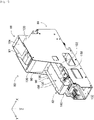
Fig. 1 is a perspective view showing a component mounter. -
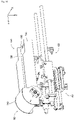
Fig. 2 is a perspective view showing a component mounting device of the component mounter. -
Fig. 3 is a perspective view showing a bulk component supply device. -
Fig. 4 is a perspective view showing a component supply unit. -
Fig. 5 is a see-through view showing an interior of the component supply unit. -
Fig. 6 is a see-through view showing a part of the interior of the component supply unit. -
Fig. 7 is a perspective view showing a component feeder. -
Fig. 8 is a perspective view showing a component scattering device. -
Fig. 9 is a perspective view showing the component scattering device. -
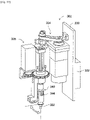
Fig. 10 is a perspective view showing a component holding head. -
Fig. 11 is a diagram showing a component receiving member, which is now accommodating an electronic circuit component. -
Fig. 12 is a block diagram showing a control device of the component mounter. -
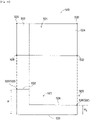
Fig. 13 is a diagram showing a component support member on which lead components are scattered as viewed from above. -
Fig. 14 is a conceptual diagram for explaining a calculation method of an actual component position of a component based on image data. -
Fig. 15 shows a plan view and a side view both showing an identical component. -
Fig. 16 is a conceptual diagram for explaining a calculation method of an actual component position of a component based on image data. -
Fig. 17 is a diagram showing conceptually a calculated component holding position and an expected holding position. -
Fig. 18 is a diagram showing conceptually a calculated component holding position and an expected holding position. -
Fig. 19 is a diagram showing an input screen. -
Fig. 20 is a diagram showing conceptually a calculated component holding position and an expected holding position. -
Fig. 21 shows a plan view and a side view both showing the component shown inFig. 15 , which is now being oriented differently from the orientation shownFig. 15 . -
Fig. 22 shows a plan view and a side view both showing an identical component. -
Fig. 23 shows a plan view and a side view both showing the component shown inFig 22 , which is now being oriented differently from the orientation shown inFig.22 . - Hereinafter, as a mode for carrying out the present invention, an embodiment of the present invention will be described by reference to drawings.
-
Fig. 1 showscomponent mounter 10.Component mounter 10 is a device for executing a component mounting operation oncircuit base material 12.Component mounter 10 includes devicemain body 20, base material conveyance andholding device 22,component mounting device 24,imaging devices component supply device 30, bulkcomponent supply device 32, and control device (refer toFig. 12 ) 34. Examples ofcircuit base material 12 include a circuit board, a base material having a three-dimensional structure, and the like, and examples of the circuit board include a printed wiring board, a printed circuit board, and the like. - Device
main body 20 is made up offrame 40 andbeam 42 that is placed onframe 40. Base material conveyance andholding device 22 is disposed at a center offrame 40 in a longitudinal direction thereof and includesconveyance device 50 andclamp device 52.Conveyance device 50 is a device for conveyingcircuit base material 12, andclamp device 52 is a device for holdingcircuit base material 12. As a result, base material conveyance andholding device 22 conveyscircuit base material 12 and holdscircuit base material 12 fixedly in a predetermined position. In the following description, a conveyance direction ofcircuit base material 12 is referred to as an X-direction, a horizontal direction perpendicular to that direction is referred to as a Y-direction, and a vertical direction is referred to as a Z-direction. That is, a widthwise direction ofcomponent mounter 10 is the X-direction, and a front-rear direction thereof is the Y-direction. -
Component mounting device 24 is disposed onbeam 42 and includes twowork heads head moving device 64.Work heads Fig. 2 ) 66 and hold a component usingsuction nozzle 66. In addition, workhead moving device 64 includesX-direction moving device 68, Y-direction moving device 70, and Z-direction moving device 72. Then, twowork heads frame 40 byX-direction moving device 68 and Y-direction moving device 70. Additionally, as shown inFig. 2 ,work heads sliders 74, 76, respectively, through a one-touch action by an operator without using any tool to thereby be detachably attached thereto, and Z-direction moving device 72 movessliders 74, 76 in an up-down direction individually and separately. That is,work heads direction moving device 72. -
Imaging device 26 is attached to slider 74 in such a state thatimaging device 26 is directed downwards and is moved in the X-direction, Y-direction, and Z-direction together withwork head 60. As a result,imaging device 26 images any position onframe 40. As shown inFig. 1 ,imaging device 28 is disposed between base material conveyance andholding device 22 onframe 40 andcomponent supply device 30 in such a state thatimaging device 28 is directed upwards. As a result,imaging device 28 images components held bysuction nozzles 66 ofwork heads -
Component supply device 30 is disposed at a first end portion ofcomponent mounting device 24 in a front-rear direction offrame 40.Component supply device 30 includes tray-typecomponent supply device 78 and a feeder-type component supply device (not shown). Tray-typecomponent supply device 78 is a device for supplying components in such a state that the components are placed on a tray. Feeder-type component supply device is a device for supplying components by a tape feeder (not shown), a stick feeder (not shown), a bulk component feeder device for supplying multiple components which are scattered separately, or the like. - Bulk
component supply device 32 is disposed at a second end portion ofcomponent mounting device 24 in the front-rear direction offrame 40. Bulkcomponent supply device 32 is a device for aligning multiple components which are scattered separately and supplying the multiple components in such an aligned state. That is, bulkcomponent supply device 32 is a device for aligning multiple components which are oriented arbitrarily into a predetermined orientation and supplying the multiple components which are now aligned into the predetermined orientation. Hereinafter, the configuration ofcomponent supply device 32 will be described in detail. Examples of components which are supplied bycomponent supply device 30 and bulkcomponent supply device 32 include electronic circuit components, constituent components of a solar cell, constituent components of a power module, and the like. In addition, the electronic circuit components include a component with a lead, a component without a lead, and the like. - As shown in
Fig. 3 , bulkcomponent supply device 32 includesmain body 80,component supply units 82, two-dimensional imaging device 84, andcomponent delivery device 86. -
Component supply unit 82 includes component feeder (refer toFig. 7 ) 88,frame 89, component scattering device (refer toFig. 4 ) 90, and component return device (refer toFig. 4 ) 92, and thesecomponent feeder 88,frame 89,component scattering device 90, andcomponent return device 92 are configured as an integral unit.Component supply unit 82 is detachably positioned onmain body 80 by an operator through a one-touch action without using any tool to thereby be detachably attached thereto, and fivecomponent supply units 82 are disposed side by side into a row in the X-direction in bulkcomponent supply device 32. - As shown in
Figs. 4 to 7 ,component feeder 88 has a generally rectangular parallelepiped box-like shape and is disposed in such a manner as to extend in the Y direction. The Y-direction will be described as a front-rear direction ofcomponent feeder 88, a direction toward an end ofcomponent supply unit 82 wherecomponent return device 92 is disposed will be described as front or forward, and a direction toward an end ofcomponent supply unit 82 wherecomponent feeder 88 is disposed will be described as rear or rearward. -
Component feeder 88 is opened in an upper surface and a front surface thereof, and an opening in the upper surface is made intocomponent loading port 97, while an opening in the front surface is made intocomponent discharge port 98. Incomponent feeder 88,inclined plate 104 is disposed below loadingport 97.Inclined plate 104 is disposed in such a manner as to be inclined downward in a direction toward a center ofcomponent feeder 88 from a rear end face thereof. - In addition,
conveyor device 106 is disposed at the front ofinclined plate 104, as shown inFig. 5 .Conveyor device 106 is disposed in such a manner as to be inclined upward from a front end portion ofinclined plate 104 toward the front ofcomponent feeder 88.Conveyor belt 112 ofconveyor device 106 is caused to rotate in a counterclockwise direction inFig. 5 by driving electromagnetic motor (refer toFig. 12 ) 116. That is, a conveyance direction ofconveyor device 106 is referred to as an obliquely upward direction extending forwards from the front end portion ofinclined plate 104 . - Further, inclined
plate 126 is disposed below a front end portion ofconveyor device 106.Inclined plate 126 is disposed in such a manner as to extend from a front end face ofcomponent feeder 88 towardsbelow conveyor device 106, and a rear end portion ofinclined plate 126 is inclined obliquely downward. Furthermore, inclinedplate 128 is also disposed belowinclined plate 126.Inclined plate 128 is disposed to extend from a position lying below a center portion ofconveyor device 106 towardsdischarge port 98 ofcomponent feeder 88 in such a manner as to be inclined so that a front end portion ofinclined plate 128 is positioned further downward. - In addition, as shown in
Fig. 4 ,frame 89 is made up of pair of side frames 130 and connectingframe 132. Pair of side frames 130 are erected in such a manner as to extend parallel to each other and in the Y-direction while facing each other. Then, connectingframe 132 is placed at lower ends of pair of side frames 130 in such a manner as to straddle a space defined therebetween, whereby pair of side frames 130 are connected together by connectingframe 132.Frame 89 functions as a housing ofcomponent supply unit 82; however,frame 89 may not function as a housing but may constitute a reinforcing member, an outer shell member, a housing, a cover, a casing, or the like ofcomponent supply unit 82. Further, a distance between pair of side frames 130 is set slightly larger than a widthwise dimension ofcomponent feeder 88, so thatcomponent feeder 88 can detachably be mounted between pair of side frames 130 through a one-touch action while being positioned therebetween. Detachable mounting through the one-touch action means thatcomponent feeder 88 is detachably mounted in position in a repeatable fashion by the operator without using any tool or the like. - Further, as shown in
Figs. 4 and5 ,component scattering device 90 includescomponent support member 150 and component supportmember moving device 152.Component support member 150 is made up ofstage 156 and pair ofside wall portions 158.Stage 156 has a generally longitudinal plate-like shape and is disposed in such a manner as to extend to the front from belowcomponent feeder 88 mounted between pair of side frames 130. Additionally, a widthwise dimension ofstage 156 is set approximately the same as the distance defined between pair of side frames 130, that is, a widthwise dimension offrame 89, and a rear end portion ofstage 156 is positioned between pair of side frames 130. An upper surface ofstage 156 is generally horizontal and is disposed in such a state that a slight clearance is provided between a front end portion ofinclined plate 128 ofcomponent feeder 88 and itself at a rear end portion thereof as shown inFig. 5 . Further, as shown inFig. 4 , pair ofside wall portions 158 are individually erected along both longitudinal side portions ofstage 156 in such a manner as to be fixed thereto, and upper ends of bothside wall portions 158 extend further upwards than the upper surface ofstage 156. - Component support
member moving device 152 causescomponent support member 150 to slide in the Y-direction as air cylinder (refer toFig. 12 ) 166 operates accordingly. As this occurs,component support member 150 moves between a retracted state (refer toFig. 6 ) in whichcomponent support member 150 is retracted underneathcomponent feeder 88 and an exposed state (refer toFig. 5 ) in whichcomponent support member 150 is exposed from underneathcomponent feeder 88. - As shown in
Fig. 8 ,component return device 92 includescomponent accommodating container 180 andcontainer swing device 181.Component accommodating container 180 has a generally box-like shape and an arc-shaped bottom surface. A widthwise dimension ofcomponent accommodating container 180 is set approximately the same as the widthwise dimension ofstage 156. Thatcomponent accommodating container 180 is held in a swinging fashion at a front end portion ofstage 156 and swings ascontainer swing device 181 operates accordingly. When it swings,component accommodating container 180 swings between an accommodation orientation (refer toFig. 8 ) in which an opening thereof is directed upwards and a return orientation (refer toFig. 9 ) in which the opening is directed towards the upper surface ofstage 156 ofcomponent support member 150. - As shown in
Fig. 3 , two-dimensional imaging device 84 includescamera 290 andcamera moving device 292.Camera moving device 292 includesguide rail 296 andslider 298.Guide rail 296 is fixed tomain body 80 abovecomponent feeders 88 in such a manner as to extend in a widthwise direction (X-direction) of bulkcomponent supply device 32.Slider 298 is slidably attached to guiderail 296 and slides to any position as electromagnetic motor (refer toFig. 12 ) 299 operates accordingly.Cameras 290 is provided one and is fixedly attached toslider 298 in such a state that camera 29 is directed downwards.Camera 290 is a three-dimensional camera which can detect height information, depth information, or the like of a three-dimensional imaging target object or a two-dimensional camera without a three-dimensional image processing device which cannot detect height information, depth information, or the like of a three-dimensional imaging target object. In addition,camera 290 does not employ a telecentric lens system in which an aperture stop is located in a focal point position of a lens but employs a general lens, that is, a lens whose angle of view is not 0 degree. -
Component delivery device 86 includes, as shown inFig. 3 , component holdinghead moving device 300,component holding head 302, and twoshuttle devices 304. - Component holding
head moving device 300 includesX-direction moving device 310, Y-direction moving device 312, and Z-direction moving device 314. Y-direction moving device 312 includes Y-slider 316 which is disposed abovecomponent supply units 82 in such a manner as to extend in the X-direction, and Y-slider 316 moves to any position in the Y-direction as electromagnetic motor (refer toFig. 12 ) 319 is driven accordingly.X-direction moving device 310 includes X-slider 320 which is disposed on a side surface of Y-slider 316, and X-slider 320 moves to any position in the X-direction as electromagnetic motor (refer toFig. 12 ) 321 is driven accordingly. Z-direction moving device 314 includes Z-slider 322 which is disposed on a side surface ofX-slider 320, and Z-slider 322 moves to any position in the Z-direction as electromagnetic motor (refer toFig. 12 ) 323 is driven accordingly. - As shown in
Fig. 10 ,component holding head 302 includes headmain body 330,suction nozzle 332,nozzle pivoting device 334, andnozzle rotation device 335. Headmain body 330 is formed integrally with Z-slider 322.Suction nozzle 332 is configured to hold a component and is detachably attached to a lower end portion ofholder 340.Holder 340 is configured to be bendable onsupport shaft 344, andholder 340 is bent upwards through 90 degrees asnozzle pivoting device 334 operates accordingly. As a result,suction nozzle 332, which is attached to the lower end portion ofholder 340, pivots through 90° to be positioned in a pivoted position and then stops there. That is,suction nozzle 332 pivots between a non-pivoted position and the pivoted position asnozzle pivoting device 334 operates accordingly. Of course,suction nozzle 332 can be positioned to stop at an angle position between the non-pivoted position and the pivoted position.Nozzle rotation device 335 causessuction nozzle 332 to rotate around an axis center thereof. - As shown in
Fig. 3 , twoshuttle devices 304 each includecomponent carrier 388 and componentcarrier moving device 390 and are fixed tomain body 80 in such a manner as to be aligned side by side in a lateral direction along front ends ofcomponent supply units 82.Component carrier 388 includes fivecomponent receiving members 392, which are attached thereto while being aligned in a row in the lateral direction, so that components are placed individually and separately oncomponent receiving members 392. - Bulk
component supply device 32 can supply various types of components, and various types ofcomponent receiving members 392 are prepared so as to match shapes of those various types of components. Here, as an electronic component that is supplied by bulkcomponent supply device 32, as shown inFig. 11 ,component receiving member 392 will be described which matcheslead component 410 having leads.Lead component 410 is made up of a block-shaped componentmain body 412 and twoleads 414 protruding from a bottom surface of componentmain body 412. -
Component receiving member 392 has formed therein component receiving recessedsection 416 having a shape matching the shape oflead component 410. Component receiving recessedsection 416 is a recessed section having a stepped shape and is made up of main body section receiving recessedsection 418, which opens in an upper surface ofcomponent receiving member 392, and lead receiving recessedsection 420, which is formed to provide an opening in a bottom surface of main body section receiving recessedsection 418. Then,lead component 410 is inserted inside component receiving recessedsection 416 while being oriented in such a manner that leads 414 are directed downwards. As a result,lead component 410 is placed inside component receiving recessedsection 416 in such a state that leads 414 are inserted into lead receiving recessedsection 420 and componentmain body 412 is inserted into main body section receiving recessedsection 418. - Further, as shown in
Fig. 3 , componentcarrier moving device 390 is a plate-shaped longitudinal member and is disposed at the front ends ofcomponent supply units 82 in such a manner as to extend in the front-rear direction.Component carrier 388 is disposed on an upper surface of componentcarrier moving device 390 in such a manner as to slide in the front-rear direction, so thatcomponent carrier 388 slides to an arbitrary position in the front-rear direction as electromagnetic motor (refer toFig. 12 ) 430 is driven accordingly. Whencomponent carrier 388 slides in a direction in whichcomponent carrier 388 moves towardscomponent supply units 82,component carrier 388 slides as far as a component receiving position which is located within a moving range ofcomponent holding head 302 which is moved by component holdinghead moving device 300. On the other hand, whencomponent carrier 388 slides in a direction in whichcomponent carrier 388 moves away fromcomponent supply units 82,component carrier 388 slides to a component supply position which is located within moving ranges of work heads 60, 62 which are moved by workhead moving device 64. -
Control device 34 includes, as shown inFig. 12 ,integrated control device 450, multiple individual control devices (only one is shown in the figure) 452, andimage processing device 454.Integrated control device 450 is made up mainly of a computer and is connected to base material conveyance and holdingdevice 22,component mounting device 24,imaging device 26,imaging device 28,component supply device 30, and bulkcomponent supply device 32. As a result, integratedcontrol device 450 integrally controls base material conveyance and holdingdevice 22,component mounting device 24,imaging device 26,imaging device 28,component supply device 30, and bulkcomponent supply device 32. Multipleindividual control devices 452 are each made up mainly of a computer and are provided individually and separately for base material conveyance and holdingdevice 22,component mounting device 24,imaging device 26,imaging device 28,component supply device 30, and bulk component supply device 32 (in the figure, onlyindividual control device 452 for bulkcomponent supply device 32 is shown). -
Individual control device 452 of bulkcomponent supply device 32 is connected tocomponent feeder 88,component scattering device 90,component return device 92,camera moving device 292, component holdinghead moving device 300,component holding head 302, andshuttle devices 304. As a result,individual control device 452 of bulkcomponent supply device 32controls component feeder 88,component scattering device 90,component return device 92,camera moving device 292, component holdinghead moving device 300,component holding head 302, andshuttle devices 304.Image processing device 454 is connected to two-dimensional imaging device 84 to process image data captured by two-dimensional imaging device 84. Thatimage processing device 454 is connected toindividual control device 452 of bulkcomponent supply device 32. As a result,individual control device 452 of bulkcomponent supply device 32 obtains two-dimensional image data captured by two-dimensional imaging device 84. - With the configuration that has been described heretofore,
component mounter 10 executes a component mounting operation oncircuit base material 12 which is held by base material conveyance and holdingdevice 22. Specifically speaking,circuit base material 12 is conveyed to a work position by base material conveyance and holdingdevice 22 and is fixedly held byclamp device 52 in that work position. Next,imaging device 26 moves to a position lying abovecircuit base material 12, which is now fixedly held in position, and imagescircuit base material 12. As a result, information on an error in the holding position ofcircuit base material 12 can be obtained.Component supply device 30 or bulkcomponent supply device 32 supplies a component in a predetermined supply position. A supply of a component by bulkcomponent supply device 32 will be described in detail later on. Then, either of work heads 60, 62 moves to a position lying above the component supply position to hold a component withsuction nozzle 66. Subsequently,work head imaging device 28, whereby the component held bysuction nozzle 66 ofwork head device 28. As a result, information on an error in the holding position of the component can be obtained. Then,work head circuit base material 12 to mount the component which workhead circuit base material 12 by correcting an error in the holding position ofcircuit base material 12 and the error in the holding position of the component. - In bulk
component supply device 32,components 410 of one type are loaded into loadingport 97 of onecomponent feeder 88 by the operator, and theselead components 410 so loaded are supplied in such a state that they are placed oncomponent receiving member 392 ofcomponent carrier 388 ascomponent supply unit 82 andcomponent delivery device 86 operate accordingly. - Specifically speaking, the operator loads lead
components 410 of one type into loadingport 97 opened in the upper surface of eachcomponent feeder 88. As this occurs,component support member 150 is caused to move to the position lying belowcomponent feeder 88 in question as a result of operation of component supportmember moving device 152 to thereby stay in the retracted state (refer toFig. 6 ). Withcomponent support member 150 staying in the retracted state,component accommodating container 180, which is disposed at the front end portion ofcomponent support member 150, is positioned at the front ofcomponent feeder 88, assuming an orientation (an accommodating orientation) in which the opening ofcomponent accommodating container 180 is directed upwards. - Lead
components 410 loaded from loading port ofinlet 97 ofcomponent feeder 88 fall oninclined plate 104 ofcomponent feeder 88 and roll down to a lower end ofinclined plate 104 at the front thereof. Then,lead components 410, which have rolled down to the lower end at the front ofinclined plate 104, are accumulated between the lower end ofinclined plate 104 at the front thereof and a lower end ofconveyor device 106 at the rear thereof. Then,conveyor belt 112 ofconveyor device 106 circulates counterclockwise, as seen inFig. 6 , asconveyor device 106 operates accordingly. As this occurs,lead components 410, which are accumulated betweeninclined plate 104 andconveyor belt 112, are then conveyed obliquely upwards byconveyor belt 112. - Then, Lead
components 410, which are conveyed byconveyor belt 112, fall oninclined plate 126 from an upper end ofconveyor device 106 at the front thereof. Leadcomponents 410, which have fallen oninclined plate 126, then roll down oninclined plate 126 to the rear to fall ontoinclined plate 128. Leadcomponents 410,which have fallen oninclined plate 128, then roll down to the front to be discharged fromdischarge port 98 ofcomponent feeder 88 at the front thereof. - As a result,
lead components 410, which have been discharged fromdischarge port 98 ofcomponent feeder 88, are accommodated insidecomponent accommodating container 180. Then, when a predetermined amount oflead components 410 is discharged fromcomponent feeder 88, that is, whenconveyor device 106 operates by a certain amount,conveyor device 106 stops. Next,component support member 150 moves from the retracted state towards the front as component supportmember moving device 152 operates accordingly. - Then,
container swinging device 181 ofcomponent return device 92 operates at a timing whencomponent support member 150 moves a predetermined amount from the retracted state towards the front wherecomponent support member 150 is put in an exposed state, wherebycomponent accommodating container 180 starts swinging. As a result, the orientation ofcomponent accommodating container 180 vigorously changes from the orientation(accommodating orientation) in which the opening is directed upwards to an orientation (returned orientation) in which the opening is directed towardsstage 156. As this occurs,lead components 410, which are accommodated incomponent accommodating container 180, are vigorously discharged towardsstage 156. As a result,lead components 410 of one type are scattered fromcomponent accommodating container 180 ontostage 156. In this case, for scattering oflead components 410, situations are considered in which leadcomponents 410 are scattered while overlapping one another and in which leadcomponents 410 are scattered separately from one another without overlapping one another. - When
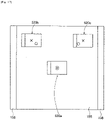
lead components 410 are scattered fromcomponent feeder 88 ontostage 156 ofcomponent support member 150 in accordance with the procedure described above,camera 290 of two-dimensional imaging device 84 moves to a position lying abovecomponent support member 150 as a result of operation ofcamera moving device 292 and then stops in an imaging position to imagelead components 410. As a result, as shown inFig. 13 , two-dimensional image data of each of multiplelead components 410 which are scattered on the upper surface ofcomponent support member 150 is obtained. Then, information on positions of multiplelead components 410 which are scattered on the upper surface ofcomponent support member 150, orientations of thoselead components 410 oncomponent support member 150, and the like is calculated based on the two-dimensional image data so obtained. - Then,
component holding head 302 is caused to move to a position lying above onelead component 410 based on the information on the position and orientation thereof so calculated and the like as component holdinghead moving device 300 operates accordingly, wherebylead component 410 in question is picked up and held bysuction nozzle 332. When a lead component is picked up and held bysuction nozzle 332,suction nozzle 332 is positioned in the non-pivoted position with a suction port thereof directed downwards, and a pickup surface, which constitutes the suction port, stays parallel to a horizontal plane. - Then,
component holding head 302 moves upwards away fromcomponent carrier 388 afterlead component 410 is held bysuction nozzle 332. As this occurs,component carrier 388 is then moved to the component receiving position as a result of operation of componentcarrier moving device 390. Whencomponent holding head 302 moves upwards away fromcomponent carrier 388,suction nozzle 332 is pivoted to the pivoted position.Suction nozzle 332 is caused to revolve bynozzle rotation device 335 which operates accordingly so that leads 414 oflead component 410 held bysuction nozzle 332, which is now positioned in the pivoted position, are directed downwards in a vertical direction. - When
component holding head 302 moves upwards to stay abovecomponent carrier 388,lead component 410 whose leads 414 are directed downwards in the vertical direction are inserted into component receiving recessedsection 416 ofcomponent receiving member 392. As a result, as shown inFig. 11 ,lead component 410 is placed incomponent receiving member 392 in such a state that leads 414 are directed downwards in the vertical direction. - Then, when
lead component 410 is placed incomponent receiving member 392,component carrier 388 moves to the component supply position as componentcarrier moving device 390 operates accordingly. Sincecomponent carrier 388, which has moved to the component supply position, is now positioned within the moving ranges of work heads 60, 62, in bulkcomponent supply device 32,lead component 410 is supplied tocomponent mounter 10 in this position. In this way, in bulkcomponent supply device 32,lead component 410 is supplied while being placed incomponent receiving member 392 in such a state that leads 414 are directed downwards and the upper surface, which faces the bottom surface to which leads 414 are connected, is directed upwards. As a result,suction nozzles 66 of work heads 60, 62 can suitably hold correspondinglead components 410. - As described above, with bulk
component supply device 32, components of one type are scattered fromcomponent feeder 88 ontostage 156, and the components so scattered onstage 156 are imaged bycamera 290. Then, positions and orientations of those components are calculated based on the image data so captured, and the components scattered onstage 156 are held bycomponent holding head 302 by making use of the positions and orientations so calculated. However,camera 290 used to image the components scattered onstage 156 is the two-dimensional camera, and further, no telecentric lens is used incamera 290. Therefore, when calculating positions and orientations of the components based on the image data so captured, positions and orientations of the components are calculated in consideration of a height dimension of the component. - To describe this in detail, when one component on
stage 156 is imaged bycamera 290,camera 290 performs fixed-point imaging. Specifically speaking, for example,camera 290 images the upper surface ofstage 156 once in such a state thatcamera 290 is fixed at a center ofstage 156 and at a predetermined height abovestage 156. As a result, in the case that components are scattered in positions other than the center ofstage 156, a position of a component which is calculated based on image data captured for one of those scattered components (hereinafter, referred to as an "imaged component position") differs from a position where the component is actually placed (hereinafter, referred to as an "actual component position") To describe this in detail, a case is taken into consideration in which as shown inFig. 14 , assuming that a position on the stage lying directly belowcamera 290 is referred to as an origin (0),component 500 having height dimension HR is placed in a position lying away from the origin, and in four corner portions of an upper end face ofcomponent 500 in question, onecorner portion 502 is located a distance of XR away from the origin. In this case, in an image based on image data captured bycamera 290,corner portion 502 ofcomponent 500 is positioned a distance of Xo away from the origin. This is becausecorner portion 502 ofcomponent 500, which is located the distance of XR away from the origin, and an upper surface ofstage 156 which is located the distance of Xo away from the origin are located on oneprincipal ray 510 ofcamera 290. As a result, when a position forcorner portion 502 ofcomponent 500 is calculated based on the image data captured bycamera 290,corner portion 502 is calculated as being located the distance of Xo away from the origin. Thus, actual component position XR and imaged component position XO ofcorner portion 502 ofcomponent 500 differ from each other. - Then, an actual component position of
corner portion 502 is calculated by making use of height dimension HR ofcomponent 500 and height dimension HO at whichcamera 290 is disposed. That is, the following expression is established between actual component position XR and imaged component position Xo.
- As a result, actual component position XR is calculated according to the following expression.

- However, if
corner portion 502 lies directly belowcamera 290, that is, at the origin (O), the actual component position and the imaged component position will coincide with each other, irrespective of the height dimension of the component. - When actual component position XR of
corner portion 502 ofcomponent 500 is calculated in the way described above, actual component positions XR of three remainingcorner portions 502 ofcomponent 500 are also calculated using the same method. Then, a holding position ofcomponent 500 is calculated based on actual component positions XR of the four corner portions ofcomponent 500. For example, in the case that a center of the upper end face ofcomponent 500 constitutes an expected holding position, a center position of actual component positions XR of the four corner portions is calculated as a component holding position. - However, the component holding position calculated by the method described above is effective only in a case in which when the height dimension of the upper end face of the component is uniform, and hence, in the case that a height dimension of an upper end face of a component is not uniform, there may be a case in which a component holding position calculated deviates from an expected holding position of the component. To describe this in detail, with
component 520 shown inFig. 15 , a first surface ofcomponent 500 is made into a flat surface, whereas a second surface ofcomponent 500 is made into a steppedsurface 521. That steppedsurface 521 is made up of projectingsection 522, which is located at a first end portion in a longitudinal direction, and recessedsection 524, which is located at a second end portion in the longitudinal direction. Then, a height dimension of projectingsection 522 is referred to as H1, and a height dimension of recessedsection 524 is referred to as H2. - Thus,
component 520 has the two height dimensions (H1, H2); however, since a component holding position is calculated using one height dimension in the method described above, a holding position ofcomponent 520 is experimentally calculated using, for example, the height dimension (Hi) of projectingsection 522. Specifically speaking, in fourcorner portions component 520, actual component positions ofcorner portions section 522 are calculated using the height dimension (Hi). For this calculation, since the height dimension ofcorner portions corner portions corner portions component 520, actual component positions ofcorner portions section 524 are calculated using the height dimension (Hi). For this calculation, since the height dimension ofcorner portions corner portions Fig. 16 , when positions ofcorner portions corner portions corner portions component 520 is calculated by use of the positions ofcorner portions 530. 532 so calculated, as shown inFig. 17 , a component holding position (denoted by mark o) calculated based on captured image data constitutes a position which differs from an expected holding position (denoted by mark x) . However, sincecomponent 520a is positioned directly belowcamera 290, and an actual component position and an imaged component position ofcomponent 520a coincide with each other, irrespective of the height dimension of the component, a calculated component holding position (denoted by mark o) and an expected holding position (denoted by mark x) coincide with each other. On the other hand, withcomponents components camera 290 on which an optical axis ray ofcamera 290 falls, and actual component positions ofcorner portions corner portions components camera 290, that is, closer tocomponent 520a. - In addition, a holding position of
component 520 is experimentally calculated by use of, for example, the height dimension (H2) of recessedsection 524. Specifically speaking, in fourcorner portions component 520, actual component positions ofcorner portions section 524 are calculated by use of the height dimension (H2). For this calculation, since the height dimension ofcorner portions corner portions corner portions component 520, actual component positions ofcorner portions section 522 are calculated by use of the height dimension (H2). For this calculation, since the height dimension ofcorner portions corner portions Fig. 16 , when positions ofcorner portions corner portions corner portions corner portions Fig 18 . However, sincecomponent 520a is positioned directly belowcamera 290, and an actual component position and an imaged component position ofcomponent 520a coincide with each other, irrespective of the height dimension of the component, a calculated component holding position (denoted by mark o) and an expected holding position (denoted by mark x) coincide with each other. On the other hand, withcomponents components camera 290, and actual component positions ofcorner portions corner portions components camera 290, that is, farther away fromcomponent 520a. - As described above, when the calculated component holding positions (denoted by mark o) deviate from the expected holding positions (denoted by mark x) of the components, the components cannot suitably be held. As a result, with bulk
component supply device 32, multiple different height dimensions of a holding target component are inputted in consideration of the fact that height dimensions of an upper end face of the component are different from each other, and a component holding position is calculated by making use of the multiple height dimensions. Specifically speaking, in a program creation device (not illustrated) of a program for controlling the operation ofcomponent mounter 10, sixinput box areas 552a to 552f are displayed oninput screen 550, as shown inFig. 19 .Input box area 552a is a box area into which a holding height is inputted, and a holding height of a component at which the component is held bycomponent holding head 302 is inputted. For example, with component (refer toFig. 15 ) 520, since the upper surface of recessedsection 524 constitutes a holding position wherecomponent holding head 302 holdscomponent 520, height dimension H2 of recessedsection 524 is inputted to inputbox area 552a.Input box area 552b is a box area into which an inclination angle of the holding surface is inputted, and an inclination angle of the holding surface resulting whencomponent holding head 302 holds a component is inputted. For example, in the case of component 520 (refer toFig. 15 ), since the upper surface of recessedsection 524 constitutes a holding surface wherecomponent holding head 302 holdscomponent 520, and the upper surface of recessedsection 524 constitutes a horizontal plane, 0 is inputted intoinput box area 552b. -
Input box areas 552c to 552f are box areas into which height dimensions of four sides of an upper end face of a component are inputted. For example, in the case of component 520 (refer toFig. 15 ), height dimension H1 of a side defined by only projectingsection 522, that is, a side which includescorner portion 526 andcorner portion 528 is inputted to inputbox area 552c. In addition, height dimension H2 of a side defined by only recessedsection 524, that is, a side includingcorner portion 530 andcorner portion 532 is inputted to inputbox area 552e. Then, height dimensions of sides defined by projectingsection 522 and recessedsection 524, that is, a side includingcorner portion 526 andcorner portion 530 and a side includingcorner portion 528 andcorner portion 532 are inputted to inputbox area 552d andinput box area 552f. However, the sides defined by projectingsection 522 and recessedsection 524 are formed into a stepped shape, and a height dimension of a higher portion of the step-shaped side is H1, while a height dimension of a lower portion of the step-shaped side is H2. Then, in those step-shaped sides, height dimensions of portions which occupy a larger area are inputted intoinput box area 552d andinput box area 552f. That is, as can be seen fromFig. 15 , in the sides defined by projectingsection 522 and recessedsection 524, since the area of the portion defined by recessedsection 524 is large, height dimension H2 is inputted intoinput box area 552d andinput box area 552f. - A holding operation of
components 520 which are scattered onstage 156 is executed by making use of the holding height ofcomponent 520, the inclination angle of the holding surface, and the height dimensions of the four sides of steppedsurface 521 ofcomponent 520 which are inputted intoinput screen 550 for storage. To describe this in detail, actual component positions ofindividual corner portions component 520 are calculated based on image data ofcomponent 520 on the stage which is captured bycamera 290 and the height dimensions of the four sides of steppedsurface 521 ofcomponent 520 which are inputted frominput screen 550. That is, imaged component positions Xo ofcorner portions corner portions input screen 550. - Specifically speaking, average value Hav of the height dimensions of the four sides which are inputted into
input screen 550 is calculated. That is, in the case ofcomponent 520, average value Hav (=(H1+3H2)/4) of the height dimensions of the four sides is calculated. Then, using average value Hav of the height dimensions of the four sides so calculated as the height dimension ofcomponent 520, actual component positions XR ofindividual corner portions component 520 are calculated by use of the expression described before. That is, actual component positions XR are calculated in accordance with the following expression.
- Then, when actual component positions XR of four
corner portions component 520 are calculated, a center position of actual component positions XR of fourcorner portions component 520. Then,component holding head 302 is caused to move to a position lying above the calculated component holding position as component holdinghead moving device 300 operates accordingly. In addition, incomponent holding head 302, the pivot angle ofsuction nozzle 332 is controlled so as to causesuction nozzle 332 to stay at right angles to the inclination angle of the holding surface which is inputted intoinput screen 550 asnozzle pivoting device 334 operates accordingly. Then,component holding head 302 descends as component holdinghead moving device 300 operates accordingly, andcomponent 520 is held bysuction nozzle 332 at the holding height which is inputted intoinput screen 550. As described above, when a component holding position ofcomponent 520 is calculated using average value Hav of the height dimensions of the four sides as the height dimension ofcomponent 520, as shown inFig. 20 , the component holding position (denoted by mark o) so calculated and an expected holding position (denoted by mark x) coincide with each other. That is, actual dimensions of components which are scattered in predetermined positions on the stage coincide with the dimensions of the components which are imaged and recognized. In other words, the component holding head can suitably hold a target component based on the shapes, positions, and orientations of the components which are scattered on the stage. As a result, a suitable component holding operation can be secured. It is desirable that the component holding position ofcomponent 520 constitutes a position of center of gravity ofcomponent 520 whencomponent 520 is held by the holding tool. -
Component 520 is held bycomponent holding head 302 whilecomponent 520 is oriented in such a manner that steppedsurface 521 is directed upwards as shown inFig. 15 ; however,component 520 is held bycomponent holding head 302 whilecomponent 520 is oriented, in addition to that orientation described above, in such a manner thatflat surface 533, which is opposite to steppedsurface 521, is directed upwards as shown inFig. 21 . To make this happen, height dimensions of four sides ofcomponent 520, which is now oriented in such a manner thatflat surface 533 is directed upwards, are inputted oninput screen 550. - Specifically speaking, with
component 520 oriented in such a manner thatflat surface 533 is directed upwards,flat surface 533 is inclined. In this case,corner portions flat surface 533 positioned above recessedsection 524 of steppedsurface 521 constitute a lowest position offlat surface 533, and height dimensions ofcorner portions corner portions flat surface 533 positioned above projectingsection 522 of steppedsurface 521 constitute a highest position offlat surface 533, and height dimensions ofcorner portions - Thus, for
component 520 which is oriented in such a manner thatflat surface 533 is directed upwards, height dimension H3 of a side includingcorner portion 534 andcorner portion 536 offlat surface 533 is inputted intoinput box area 552c oninput screen 550. In addition, height dimension H4 of a side includingcorner portion 538 andcorner portion 540 offlat surface 533 is inputted intoinput box area 552e. Height dimensions of a side includingcorner portion 534 andcorner portion 538 and a side includingcorner portion 536 andcorner portion 540 offlat surface 533 are inputted intoinput box area 552d andinput box area 552f, respectively. However, the side includingcorner portion 534 andcorner portion 538 and the side includingcorner portion 536 andcorner portion 540 are inclined, and the height dimension of the lowest portion of the side is H3, while the height dimension of the highest portion of the side is H4. Then, average height dimensions of those sides are inputted intoinput box area 552d andinput box area 552f, respectively. As a result, height dimension (H3+H4)/2 is inputted intoinput box area 552d andinput box area 552f as the height dimensions of the side includingcorner portion 534 andcorner portion 538 and the side includingcorner portion 536 andcorner portion 540. - With
component 520 which is oriented in such a manner thatflat surface 533 is directed upwards, a center offlat surface 533 constitutes a holding position ofcomponent 520. As a result, a mean height dimension between the side includingcorner portion 534 andcorner portion 536 and the side includingcorner portion 538 andcorner portion 540, that is, height dimension (H3+H4)/2 is inputted intoinput box area 552a oninput screen 550 as a holding height ofcomponent 520. In addition, withcomponent 520 which is oriented in such a manner thatflat surface 533 is directed upwards, sinceflat surface 533 constitutes the holding surface ofcomponent 520, andflat surface 533 is inclined, an inclination angle offlat surface 533, for example, 30°, is inputted intoinput box area 552b oninput screen 550. - Then, a holding operation of
components 520 which are scattered onstage 156 is executed by making use of the holding height ofcomponent 520, the inclination angle of the holding surface, and the height dimensions of the four sides offlat surface 533 ofcomponent 520 which are inputted intoinput screen 550. A calculation method of calculating a holding position ofcomponent 520 which is oriented in such a manner thatflat surface 533 is directed upwards and a holding operation method ofcomponent 520 so oriented are the same as those forcomponent 520 which is oriented in such a manner that steppedsurface 521 is directed upwards, and hence, the description of those methods will be omitted here. However, with the holding operation ofcomponent 520 which is oriented in such a manner thatflat surface 533 is directed upwards, the pivoting angle ofsuction nozzle 332 is adjusted so thatsuction nozzle 332 stays at right angles to the inclination angle of the holding surface which is inputted intoinput screen 550, that is, 30°, whereaftercomponent 520 is held bysuction nozzle 332 so adjusted. In other words, the component is held after the surface of the suction port ofsuction nozzle 332 is adjusted to be parallel to the inclined holding surface. - As described heretofore, the holding height of
component 520, the inclination angle of the holding surface, and the height dimensions of the four sides ofcomponent 520 are inputted for each orientation of the component ofcomponents 520 of one type, that is, for the orientation in which steppedsurface 521 is directed upwards and the orientation in whichflat surface 533 is directed upwards. As a result,components 520 which are scattered in various orientations onstage 156 can suitably be held. Components of one type means components having the same outside dimensions and further components having the same function. - In addition, with bulk
component supply device 32, components of different types can be supplied by changing the types of components which are loaded intocomponent feeder 88. To cope with this, height dimensions of four sides of components of a type which differs fromcomponent 520, specifically,component 560 shown inFig. 22 are allowed to be inputted oninput screen 550. - Specifically speaking, in the case of
component 560, a first surface ofcomponent 560 is made intoflat surface 561, while a second surface is made into steppedsurface 562. This steppedsurface 562 is made up ofcenter section 563 which is positioned at a center portion in a lengthwise direction, projectingsection 564 which is positioned at a first end portion in the lengthwise direction, and recessedsection 566 which is positioned at a second end portion of steppedsurface 562 in the lengthwise direction thereof. Then, a height dimension ofcenter section 563 is referred to as H5, a height dimension of projectingsection 564 is referred to as H6, and a height dimension of recessedsection 566 is referred to as H7. - As a result, with
component 560 which is oriented in such a manner that steppedsurface 562 is directed upwards, height dimension H6 of a side defined by only projectingsection 564, that is, a side includingcorner portion 568 andcorner portion 570 is inputted intoinput box area 552c oninput screen 550. In addition, height dimension H7 of a side defined by only recessedsection 566, that is, a side includingcorner portion 572 andcorner portion 574 is inputted intoinput box area 552e. Further, height dimensions of sides defined bycenter section 563, projectingsection 564, and recessedsection 566, that is, a side includingcorner portion 568 andcorner portion 572 and a side includingcorner portion 570 andcorner portion 574 are inputted intoinput box area 552d andinput box area 552f, respectively. However, since the sides defined bycenter section 563, projectingsection 564, and recessedsection 566 are each formed into a step-like shape, height dimensions of portions of the sides which occupy a larger area of the sides are inputted intoinput box area 552d, andinput box area 552f. That is, as can be seen fromFig. 22 , in the side shown therein, since the portion corresponding to centersection 563 has a larger area and hence constitutes a surface suitable forcomponent 560 to be picked up through stable suction, height dimension H5 ofcenter section 563 is inputted intoinput box area 552d andinput box area 552f. - With
component 560 which is oriented in such a manner that steppedsurface 562 is directed upwards, a center ofcenter section 563 constitutes a holding position ofcomponent 560. As a result, height dimension H5 ofcenter section 563 is inputted intoinput box area 552a oninput screen 550 as a holding height ofcomponent 560. In addition, withcomponent 560 which is oriented in such a manner that steppedsurface 562 is directed upwards, sincecenter section 563 constitutes a holding surface ofcomponent 560, andcenter section 563 constitutes a horizontal plane, 0 is inputted intoinput box area 552b. Then, a holding operation ofcomponents 560 which are scattered onstage 156 while being oriented in such a manner that steppedsurfaces 562 are directed upwards is executed by making use of the holding height ofcomponent 560, an inclination angle of the holding surface, and the height dimensions of the four sides of the steppedsurface 562 which are inputted intoinput screen 550. A calculation method of calculating a holding position ofcomponent 560 which is oriented in such a manner that steppedsurface 562 is directed upwards and a holding operation method ofcomponent 560 so oriented are the same as those forcomponent 520 which is oriented in such a manner that steppedsurface 521 is directed upwards, and hence, the description of those methods will be omitted here. - In addition, with
component 560, too, as withcomponent 520, not only iscomponent 560 picked up bycomponent holding head 302 whencomponent 560 is oriented in such a state that steppedsurface 562 is directed upwards but alsocomponent 560 is picked up bycomponent holding head 302 whencomponent 560 is oriented in such a state thatflat surface 561, which is opposite to steppedsurface 562, is directed upwards as shown inFig. 23 . As a result, height dimensions of four sides ofcomponent 560 which is oriented in such a manner thatflat surface 561 is directed upwards are inputted oninput screen 550. - Specifically speaking, also with
component 560, whencomponent 560 is oriented in such a manner thatflat surface 561 is directed upwards,flat surface 561 is inclined. In this case,corner portions flat surface 561 which is positioned above recessedsection 566 of steppedsurface 562 constitute a lowest position offlat surface 561, and height dimensions ofcorner portions corner portions flat surface 561 which is positioned above projectingsection 564 of steppedsurface 562 constitute a highest position offlat surface 561, and height dimensions ofcorner portions - As a result, height dimension H8 of the side including
corner portion 576 andcorner portion 578 offlat surface 561 ofcomponent 560 which is oriented in such a manner thatflat surface 561 is directed upwards is inputted intoinput box area 552c oninput screen 550. In addition, height dimension H9 of the side includingcorner portion 580 andcorner portion 582 offlat surface 561 is inputted intoinput box area 552e. Further, the height dimensions of the side includingcorner portion 576 andcorner portion 580 and the side includingcorner portion 578 andcorner portion 582 offlat surface 561 are inputted to inputbox area 552d andinput box area 552f. However, the side includingcorner portion 576 andcorner portion 580 and the side includingcorner portion 578 andcorner portion 582 are inclined, and the height dimensions of the lowest portions of the sides are H8, and the height dimensions of the highest portions of the sides are H9. Then, average height dimensions of those sides are inputted intoinput box area 552d andinput box area 552f, respectively. As a result, height dimension (H8+H9)/2 is inputted intoinput box area 552d andinput box area 552f as the height dimensions of the side includingcorner portion 576 andcorner portion 580 and the side includingcorner portion 578 andcorner portion 582. - With
component 560 which is oriented in such a manner thatflat surface 561 is directed upwards, a center offlat surface 561 constitutes a holding position ofcomponent 560. As a result, a mean height dimension between the side includingcorner portion 576 andcorner portion 578 and the side includingcorner portion 580 andcorner portion 582, that is, height dimension (H8+H9)/2 is inputted intoinput box area 552a oninput screen 550 as a holding height ofcomponent 560. In addition, withcomponent 560 which is oriented in such a manner thatflat surface 561 is directed upwards, sinceflat surface 561 constitutes a holding surface ofcomponent 560, andflat surface 561 is inclined, an inclination angle offlat surface 561, for example, 20° is inputted intoinput box area 552b oninput screen 550. - Then, a holding operation of
components 560 which are scattered onstage 156 in such an orientation thatflat surface 561 is directed upwards is executed by making use of the holding height ofcomponent 560, the inclination angle of the holding surface, and the height dimensions of the four sides offlat surface 561 ofcomponent 560 which are inputted intoinput screen 550. A calculation method of calculating a holding position ofcomponent 560 which is oriented in such a manner thatflat surface 561 is directed upwards and a holding operation method ofcomponent 560 so oriented are the same as those forcomponent 520 which is oriented in such a manner thatflat surface 533 is directed upwards, and hence, the description of those methods will be omitted here. - As described above, the holding height of the component, the inclination angle of the holding surface, and the height dimensions of the four sides of the component are inputted for each component type, that is, for each of multiple types of components. As a result, in the case that components of an arbitrary type in components of multiple types are loaded in
component feeder 88, a holding operation of components of the arbitrary type can suitably be carried out. Components of multiple types mean components having different shapes, different external dimensions, and the like. In addition, there may be a case in which components of multiple types mean components having different functions. Further, for each of components of those different types, the holding height of the component, the inclination angle of the holding surface, and the height dimensions of the four sides of the component are inputted for each of multiple orientations of scattered components. As a result, even for components of an arbitrary type of components of multiple types, components scattered onstage 156 in various orientations can suitably be held. - Bulk
component supply device 32 constitutes an example of the component holding apparatus of the present invention.Stage 156 constitutes an example of the stage.Camera 290 constitutes an example of the imaging device. - The present invention is not limited to the embodiment that has been described heretofore, and hence, the present invention can be carried out in various aspects which are modified and/or improved variously based on the knowledge of those skilled in the art to which the present invention pertains. Specifically speaking, for example, in the embodiment described above, the components are scattered on
stage 156; however, the stage need only be any type of surface as long as components can be supplied thereto. Specifically speaking, for example, the upper surface of the conveyor belt may be made to function as the stage, or the stage may be a pocket-type stage such as a tray or a stage to which components inside the component feeder are supplied while being aligned using vibrations of a bulk feeder or the like. The aspect of the present embodiment can also be applied to a case in which multiple components of the same type are supplied in multiple orientations in these devices. - In addition, in the embodiment described above, the height dimensions of the four sides of the surface of the component which is directed upwards are inputted on
input screen 550 as multiple different height dimensions in one orientation of the components of one type; however, the different height positions of two or more sides in the four sides may be inputted. Further, not only the sides but also the corner portions of the surface directed upwards may be inputted. Furthermore, not only the height dimensions of the surface of the component which is directed upwards but also height dimensions of one or more arbitrary surfaces of the multiple surfaces of the component can be inputted. For example, in the case that the suction nozzle is adopted as a component holding tool, since the surface of the component which is directed upwards constitutes the holding surface in many cases, the height dimensions of the surface of the component which is directed upwards are inputted; however, in the case that a chuck is adopted as a component holding tool, since a surface of the component which is directed sideways constitutes the holding surface in many cases, the height dimensions of the surface of the component which is directed sideways may be inputted. However, not only the height dimensions of the holding surface but also height dimensions of one or more arbitrary surfaces of the multiple surfaces of the component can be inputted. - In the embodiment described above, the component is held by
suction nozzle 332; however, the holding surface can be held by adopting holding tools of various aspects configured to hold a component such as a chuck which can hold a component, a robot arm, and the like. - In the embodiment described above, the two-dimensional camera is adopted on which the lens which differs from a telecentric lens is mounted; however, a three-dimensional camera, a two-dimensional camera on which a telecentric lens is mounted, and the like can be adopted. In addition, a configuration may be adopted in which multiple cameras are used, or the position of one camera is moved or the angle of the camera is changed so as to execute imaging multiple times, so that orientations of components which are scattered are determined based on image data captured by the imaging. Alternatively, two-dimensional images may be obtained by these various types of imaging devices.
- In addition, the holding angle of a component described in the embodiment may automatically be calculated. That is, the angle of the holding surface may be calculated from the height data of each of the components which are oriented when they are scattered by the control device. Alternatively, the input and storage of the height data of each of the components which are oriented when they are scattered may be omitted by making use of the position of each of the components which are scattered and the angle data of the holding surface when each of the components so scattered is held.
- In the embodiment described above, the present invention is applied to bulk
component supply device 32; however, in addition to the device for supplying components, the present invention can be applied to a device for holding a component and executing a mounting operation of the component, a device for only holding a component, and the like. - In addition, in the present invention, the holding target components are not limited to
components - 32: bulk component supply device (component holding apparatus), 156: stage, 290: camera (imaging device)
Claims (5)
- A component holding apparatus comprising:a stage on which components of one type are scattered; andan imaging device configured to image the components of one type which are scattered on the stage,wherein the components of one type which are scattered on the stage are held based on inputted multiple heights of the components of one type and image data captured by the imaging device.
- The component holding apparatus according to claim 1,
wherein the multiple height dimensions are inputted for each of orientations of the components of one type which are scattered on the stage. - The component holding apparatus according to claim 1,
wherein the multiple height dimensions are inputted for each component type of the components of one type which are scattered on the stage. - The component holding apparatus according to claim 3,
wherein the multiple height dimensions are also inputted for each of orientations of the components of one type which are scattered on the stage. - The component holding apparatus according to any one of claims 1 to 4,
wherein the multiple height dimensions are height dimensions of at least one plane of multiple planes of one component of the components of one type which are scattered on the stage while being oriented.
Applications Claiming Priority (1)
| Application Number | Priority Date | Filing Date | Title |
|---|---|---|---|
| PCT/JP2019/034341 WO2021044458A1 (en) | 2019-09-02 | 2019-09-02 | Component holding apparatus |
Publications (3)
| Publication Number | Publication Date |
|---|---|
| EP4027763A1 true EP4027763A1 (en) | 2022-07-13 |
| EP4027763A4 EP4027763A4 (en) | 2022-09-07 |
| EP4027763B1 EP4027763B1 (en) | 2024-08-21 |
Family
ID=74852293
Family Applications (1)
| Application Number | Title | Priority Date | Filing Date |
|---|---|---|---|
| EP19943931.6A Active EP4027763B1 (en) | 2019-09-02 | 2019-09-02 | Component holding apparatus |
Country Status (4)
| Country | Link |
|---|---|
| EP (1) | EP4027763B1 (en) |
| JP (1) | JP7339346B2 (en) |
| CN (1) | CN114342581B (en) |
| WO (1) | WO2021044458A1 (en) |
Families Citing this family (1)
| Publication number | Priority date | Publication date | Assignee | Title |
|---|---|---|---|---|
| WO2025150182A1 (en) * | 2024-01-12 | 2025-07-17 | 株式会社Fuji | Information processing device and method for creating model data |
Family Cites Families (16)
| Publication number | Priority date | Publication date | Assignee | Title |
|---|---|---|---|---|
| JP4999502B2 (en) * | 2007-03-12 | 2012-08-15 | ヤマハ発動機株式会社 | Component transfer device and surface mounter |
| JP5158686B2 (en) * | 2007-11-21 | 2013-03-06 | 富士機械製造株式会社 | Adsorption part front / back determination device and adsorption part front / back determination method |
| JP6190229B2 (en) * | 2013-09-30 | 2017-08-30 | ヤマハ発動機株式会社 | Component mounting equipment |
| CN105993212B (en) * | 2013-12-02 | 2018-11-02 | 株式会社富士 | Kludge |
| CN106465572B (en) * | 2014-06-03 | 2019-10-22 | 株式会社富士 | Bulk component supply device and component mounting device |
| CN107251673B (en) * | 2015-02-12 | 2019-10-22 | 株式会社富士 | Component supply device |
| US10206318B2 (en) * | 2015-03-03 | 2019-02-12 | Fuji Corporation | Mounting work machine |
| US10314217B2 (en) * | 2015-03-18 | 2019-06-04 | Fuji Corporation | Component supply device |
| JP6528122B2 (en) | 2015-05-15 | 2019-06-12 | パナソニックIpマネジメント株式会社 | Component picking apparatus, component picking method and component mounting apparatus |
| JP6916577B2 (en) * | 2016-09-09 | 2021-08-11 | 株式会社Fuji | Parts supply equipment |
| CN109716878B (en) * | 2016-09-22 | 2021-02-09 | 株式会社富士 | Component supply system |
| WO2018083752A1 (en) * | 2016-11-02 | 2018-05-11 | 株式会社Fuji | Component supply system |
| WO2018092228A1 (en) * | 2016-11-17 | 2018-05-24 | 株式会社Fuji | Operation machine |
| JP6698747B2 (en) * | 2018-06-07 | 2020-05-27 | 株式会社Fuji | Bulk component supply device, component mounting device, and bulk component supply method |
| JP6735329B2 (en) * | 2018-11-07 | 2020-08-05 | 株式会社Fuji | Parts holding device |
| CN110118529B (en) * | 2019-05-16 | 2020-11-24 | 中国工程物理研究院电子工程研究所 | Method for measuring size of wafer |
-
2019
- 2019-09-02 EP EP19943931.6A patent/EP4027763B1/en active Active
- 2019-09-02 WO PCT/JP2019/034341 patent/WO2021044458A1/en not_active Ceased
- 2019-09-02 JP JP2021543614A patent/JP7339346B2/en active Active
- 2019-09-02 CN CN201980099682.7A patent/CN114342581B/en active Active
Also Published As
| Publication number | Publication date |
|---|---|
| EP4027763A4 (en) | 2022-09-07 |
| EP4027763B1 (en) | 2024-08-21 |
| WO2021044458A1 (en) | 2021-03-11 |
| CN114342581A (en) | 2022-04-12 |
| JPWO2021044458A1 (en) | 2021-03-11 |
| JP7339346B2 (en) | 2023-09-05 |
| CN114342581B (en) | 2024-05-03 |
Similar Documents
| Publication | Publication Date | Title |
|---|---|---|
| US8707548B2 (en) | Electronic component mounting apparatus | |
| US11122721B2 (en) | Component supply system | |
| EP3264877B1 (en) | Component supply device and mounting device | |
| EP4027763B1 (en) | Component holding apparatus | |
| JP6921234B2 (en) | Parts supply device and parts supply method | |
| JP7733005B2 (en) | Control device including image processing device | |
| US12187549B2 (en) | Parts supply apparatus | |
| JP7212663B2 (en) | Parts supply system | |
| CN109863839B (en) | component supply system | |
| US11510352B2 (en) | Component supply device | |
| US20240134352A1 (en) | Maintenance device | |
| CN112753292B (en) | component supply device | |
| US11490553B2 (en) | Component mounting system and component grasping method | |
| WO2025177445A1 (en) | Information processing device and method for updating model data | |
| CN121890266A (en) | Component holding system and method for holding discrete components | |
| JP2025186632A (en) | Component storage device and component storage method | |
| JP2025183496A (en) | holding device | |
| WO2024003984A1 (en) | Component supply device | |
| CN111819917B (en) | Pin cutting system and pin component mounting system | |
| WO2025150182A1 (en) | Information processing device and method for creating model data | |
| CN121312272A (en) | Pickup support device and pickup support method | |
| CN117015791A (en) | Storage device and method for updating image determination processing stored in storage device | |
| WO2018179316A1 (en) | Component supply device |
Legal Events
| Date | Code | Title | Description |
|---|---|---|---|
| STAA | Information on the status of an ep patent application or granted ep patent |
Free format text: STATUS: THE INTERNATIONAL PUBLICATION HAS BEEN MADE |
|
| PUAI | Public reference made under article 153(3) epc to a published international application that has entered the european phase |
Free format text: ORIGINAL CODE: 0009012 |
|
| STAA | Information on the status of an ep patent application or granted ep patent |
Free format text: STATUS: REQUEST FOR EXAMINATION WAS MADE |
|
| 17P | Request for examination filed |
Effective date: 20220224 |
|
| AK | Designated contracting states |
Kind code of ref document: A1 Designated state(s): AL AT BE BG CH CY CZ DE DK EE ES FI FR GB GR HR HU IE IS IT LI LT LU LV MC MK MT NL NO PL PT RO RS SE SI SK SM TR |
|
| A4 | Supplementary search report drawn up and despatched |
Effective date: 20220805 |
|
| RIC1 | Information provided on ipc code assigned before grant |
Ipc: H05K 13/08 20060101ALI20220801BHEP Ipc: H05K 13/02 20060101ALI20220801BHEP Ipc: H05K 13/04 20060101AFI20220801BHEP |
|
| DAV | Request for validation of the european patent (deleted) | ||
| DAX | Request for extension of the european patent (deleted) | ||
| P01 | Opt-out of the competence of the unified patent court (upc) registered |
Effective date: 20230328 |
|
| GRAP | Despatch of communication of intention to grant a patent |
Free format text: ORIGINAL CODE: EPIDOSNIGR1 |
|
| STAA | Information on the status of an ep patent application or granted ep patent |
Free format text: STATUS: GRANT OF PATENT IS INTENDED |
|
| INTG | Intention to grant announced |
Effective date: 20240425 |
|
| GRAS | Grant fee paid |
Free format text: ORIGINAL CODE: EPIDOSNIGR3 |
|
| GRAA | (expected) grant |
Free format text: ORIGINAL CODE: 0009210 |
|
| STAA | Information on the status of an ep patent application or granted ep patent |
Free format text: STATUS: THE PATENT HAS BEEN GRANTED |
|
| AK | Designated contracting states |
Kind code of ref document: B1 Designated state(s): AL AT BE BG CH CY CZ DE DK EE ES FI FR GB GR HR HU IE IS IT LI LT LU LV MC MK MT NL NO PL PT RO RS SE SI SK SM TR |
|
| REG | Reference to a national code |
Ref country code: GB Ref legal event code: FG4D |
|
| REG | Reference to a national code |
Ref country code: CH Ref legal event code: EP |
|
| REG | Reference to a national code |
Ref country code: IE Ref legal event code: FG4D |
|
| REG | Reference to a national code |
Ref country code: DE Ref legal event code: R096 Ref document number: 602019057693 Country of ref document: DE |
|
| REG | Reference to a national code |
Ref country code: LT Ref legal event code: MG9D |
|
| REG | Reference to a national code |
Ref country code: NL Ref legal event code: MP Effective date: 20240821 |
|
| PG25 | Lapsed in a contracting state [announced via postgrant information from national office to epo] |
Ref country code: NO Free format text: LAPSE BECAUSE OF FAILURE TO SUBMIT A TRANSLATION OF THE DESCRIPTION OR TO PAY THE FEE WITHIN THE PRESCRIBED TIME-LIMIT Effective date: 20241121 |
|
| REG | Reference to a national code |
Ref country code: AT Ref legal event code: MK05 Ref document number: 1716878 Country of ref document: AT Kind code of ref document: T Effective date: 20240821 |
|
| PG25 | Lapsed in a contracting state [announced via postgrant information from national office to epo] |
Ref country code: NL Free format text: LAPSE BECAUSE OF FAILURE TO SUBMIT A TRANSLATION OF THE DESCRIPTION OR TO PAY THE FEE WITHIN THE PRESCRIBED TIME-LIMIT Effective date: 20240821 Ref country code: PT Free format text: LAPSE BECAUSE OF FAILURE TO SUBMIT A TRANSLATION OF THE DESCRIPTION OR TO PAY THE FEE WITHIN THE PRESCRIBED TIME-LIMIT Effective date: 20241223 Ref country code: FI Free format text: LAPSE BECAUSE OF FAILURE TO SUBMIT A TRANSLATION OF THE DESCRIPTION OR TO PAY THE FEE WITHIN THE PRESCRIBED TIME-LIMIT Effective date: 20240821 Ref country code: GR Free format text: LAPSE BECAUSE OF FAILURE TO SUBMIT A TRANSLATION OF THE DESCRIPTION OR TO PAY THE FEE WITHIN THE PRESCRIBED TIME-LIMIT Effective date: 20241122 Ref country code: PL Free format text: LAPSE BECAUSE OF FAILURE TO SUBMIT A TRANSLATION OF THE DESCRIPTION OR TO PAY THE FEE WITHIN THE PRESCRIBED TIME-LIMIT Effective date: 20240821 |
|
| PG25 | Lapsed in a contracting state [announced via postgrant information from national office to epo] |
Ref country code: BG Free format text: LAPSE BECAUSE OF FAILURE TO SUBMIT A TRANSLATION OF THE DESCRIPTION OR TO PAY THE FEE WITHIN THE PRESCRIBED TIME-LIMIT Effective date: 20240821 |
|
| PG25 | Lapsed in a contracting state [announced via postgrant information from national office to epo] |
Ref country code: LV Free format text: LAPSE BECAUSE OF FAILURE TO SUBMIT A TRANSLATION OF THE DESCRIPTION OR TO PAY THE FEE WITHIN THE PRESCRIBED TIME-LIMIT Effective date: 20240821 |
|
| PG25 | Lapsed in a contracting state [announced via postgrant information from national office to epo] |
Ref country code: AT Free format text: LAPSE BECAUSE OF FAILURE TO SUBMIT A TRANSLATION OF THE DESCRIPTION OR TO PAY THE FEE WITHIN THE PRESCRIBED TIME-LIMIT Effective date: 20240821 Ref country code: IS Free format text: LAPSE BECAUSE OF FAILURE TO SUBMIT A TRANSLATION OF THE DESCRIPTION OR TO PAY THE FEE WITHIN THE PRESCRIBED TIME-LIMIT Effective date: 20241221 |
|
| PG25 | Lapsed in a contracting state [announced via postgrant information from national office to epo] |
Ref country code: HR Free format text: LAPSE BECAUSE OF FAILURE TO SUBMIT A TRANSLATION OF THE DESCRIPTION OR TO PAY THE FEE WITHIN THE PRESCRIBED TIME-LIMIT Effective date: 20240821 |
|
| PG25 | Lapsed in a contracting state [announced via postgrant information from national office to epo] |
Ref country code: ES Free format text: LAPSE BECAUSE OF FAILURE TO SUBMIT A TRANSLATION OF THE DESCRIPTION OR TO PAY THE FEE WITHIN THE PRESCRIBED TIME-LIMIT Effective date: 20240821 Ref country code: RS Free format text: LAPSE BECAUSE OF FAILURE TO SUBMIT A TRANSLATION OF THE DESCRIPTION OR TO PAY THE FEE WITHIN THE PRESCRIBED TIME-LIMIT Effective date: 20241121 |
|
| PG25 | Lapsed in a contracting state [announced via postgrant information from national office to epo] |
Ref country code: RS Free format text: LAPSE BECAUSE OF FAILURE TO SUBMIT A TRANSLATION OF THE DESCRIPTION OR TO PAY THE FEE WITHIN THE PRESCRIBED TIME-LIMIT Effective date: 20241121 Ref country code: PT Free format text: LAPSE BECAUSE OF FAILURE TO SUBMIT A TRANSLATION OF THE DESCRIPTION OR TO PAY THE FEE WITHIN THE PRESCRIBED TIME-LIMIT Effective date: 20241223 Ref country code: PL Free format text: LAPSE BECAUSE OF FAILURE TO SUBMIT A TRANSLATION OF THE DESCRIPTION OR TO PAY THE FEE WITHIN THE PRESCRIBED TIME-LIMIT Effective date: 20240821 Ref country code: NO Free format text: LAPSE BECAUSE OF FAILURE TO SUBMIT A TRANSLATION OF THE DESCRIPTION OR TO PAY THE FEE WITHIN THE PRESCRIBED TIME-LIMIT Effective date: 20241121 Ref country code: NL Free format text: LAPSE BECAUSE OF FAILURE TO SUBMIT A TRANSLATION OF THE DESCRIPTION OR TO PAY THE FEE WITHIN THE PRESCRIBED TIME-LIMIT Effective date: 20240821 Ref country code: LV Free format text: LAPSE BECAUSE OF FAILURE TO SUBMIT A TRANSLATION OF THE DESCRIPTION OR TO PAY THE FEE WITHIN THE PRESCRIBED TIME-LIMIT Effective date: 20240821 Ref country code: IS Free format text: LAPSE BECAUSE OF FAILURE TO SUBMIT A TRANSLATION OF THE DESCRIPTION OR TO PAY THE FEE WITHIN THE PRESCRIBED TIME-LIMIT Effective date: 20241221 Ref country code: HR Free format text: LAPSE BECAUSE OF FAILURE TO SUBMIT A TRANSLATION OF THE DESCRIPTION OR TO PAY THE FEE WITHIN THE PRESCRIBED TIME-LIMIT Effective date: 20240821 Ref country code: GR Free format text: LAPSE BECAUSE OF FAILURE TO SUBMIT A TRANSLATION OF THE DESCRIPTION OR TO PAY THE FEE WITHIN THE PRESCRIBED TIME-LIMIT Effective date: 20241122 Ref country code: FI Free format text: LAPSE BECAUSE OF FAILURE TO SUBMIT A TRANSLATION OF THE DESCRIPTION OR TO PAY THE FEE WITHIN THE PRESCRIBED TIME-LIMIT Effective date: 20240821 Ref country code: ES Free format text: LAPSE BECAUSE OF FAILURE TO SUBMIT A TRANSLATION OF THE DESCRIPTION OR TO PAY THE FEE WITHIN THE PRESCRIBED TIME-LIMIT Effective date: 20240821 Ref country code: BG Free format text: LAPSE BECAUSE OF FAILURE TO SUBMIT A TRANSLATION OF THE DESCRIPTION OR TO PAY THE FEE WITHIN THE PRESCRIBED TIME-LIMIT Effective date: 20240821 Ref country code: AT Free format text: LAPSE BECAUSE OF FAILURE TO SUBMIT A TRANSLATION OF THE DESCRIPTION OR TO PAY THE FEE WITHIN THE PRESCRIBED TIME-LIMIT Effective date: 20240821 |
|
| PG25 | Lapsed in a contracting state [announced via postgrant information from national office to epo] |
Ref country code: DK Free format text: LAPSE BECAUSE OF FAILURE TO SUBMIT A TRANSLATION OF THE DESCRIPTION OR TO PAY THE FEE WITHIN THE PRESCRIBED TIME-LIMIT Effective date: 20240821 Ref country code: SM Free format text: LAPSE BECAUSE OF FAILURE TO SUBMIT A TRANSLATION OF THE DESCRIPTION OR TO PAY THE FEE WITHIN THE PRESCRIBED TIME-LIMIT Effective date: 20240821 Ref country code: RO Free format text: LAPSE BECAUSE OF FAILURE TO SUBMIT A TRANSLATION OF THE DESCRIPTION OR TO PAY THE FEE WITHIN THE PRESCRIBED TIME-LIMIT Effective date: 20240821 |
|
| PG25 | Lapsed in a contracting state [announced via postgrant information from national office to epo] |
Ref country code: EE Free format text: LAPSE BECAUSE OF FAILURE TO SUBMIT A TRANSLATION OF THE DESCRIPTION OR TO PAY THE FEE WITHIN THE PRESCRIBED TIME-LIMIT Effective date: 20240821 |
|
| PG25 | Lapsed in a contracting state [announced via postgrant information from national office to epo] |
Ref country code: CZ Free format text: LAPSE BECAUSE OF FAILURE TO SUBMIT A TRANSLATION OF THE DESCRIPTION OR TO PAY THE FEE WITHIN THE PRESCRIBED TIME-LIMIT Effective date: 20240821 |
|
| PG25 | Lapsed in a contracting state [announced via postgrant information from national office to epo] |
Ref country code: SK Free format text: LAPSE BECAUSE OF FAILURE TO SUBMIT A TRANSLATION OF THE DESCRIPTION OR TO PAY THE FEE WITHIN THE PRESCRIBED TIME-LIMIT Effective date: 20240821 Ref country code: IT Free format text: LAPSE BECAUSE OF FAILURE TO SUBMIT A TRANSLATION OF THE DESCRIPTION OR TO PAY THE FEE WITHIN THE PRESCRIBED TIME-LIMIT Effective date: 20240821 |
|
| REG | Reference to a national code |
Ref country code: CH Ref legal event code: PL |
|
| PG25 | Lapsed in a contracting state [announced via postgrant information from national office to epo] |
Ref country code: LU Free format text: LAPSE BECAUSE OF NON-PAYMENT OF DUE FEES Effective date: 20240902 |
|
| REG | Reference to a national code |
Ref country code: DE Ref legal event code: R097 Ref document number: 602019057693 Country of ref document: DE |
|
| PLBE | No opposition filed within time limit |
Free format text: ORIGINAL CODE: 0009261 |
|
| STAA | Information on the status of an ep patent application or granted ep patent |
Free format text: STATUS: NO OPPOSITION FILED WITHIN TIME LIMIT |
|
| PG25 | Lapsed in a contracting state [announced via postgrant information from national office to epo] |
Ref country code: MC Free format text: LAPSE BECAUSE OF FAILURE TO SUBMIT A TRANSLATION OF THE DESCRIPTION OR TO PAY THE FEE WITHIN THE PRESCRIBED TIME-LIMIT Effective date: 20240821 |
|
| REG | Reference to a national code |
Ref country code: BE Ref legal event code: MM Effective date: 20240930 |
|
| PG25 | Lapsed in a contracting state [announced via postgrant information from national office to epo] |
Ref country code: BE Free format text: LAPSE BECAUSE OF NON-PAYMENT OF DUE FEES Effective date: 20240930 |
|
| PG25 | Lapsed in a contracting state [announced via postgrant information from national office to epo] |
Ref country code: FR Free format text: LAPSE BECAUSE OF NON-PAYMENT OF DUE FEES Effective date: 20241021 |
|
| GBPC | Gb: european patent ceased through non-payment of renewal fee |
Effective date: 20241121 |
|
| PG25 | Lapsed in a contracting state [announced via postgrant information from national office to epo] |
Ref country code: CH Free format text: LAPSE BECAUSE OF NON-PAYMENT OF DUE FEES Effective date: 20240930 |
|
| PG25 | Lapsed in a contracting state [announced via postgrant information from national office to epo] |
Ref country code: IE Free format text: LAPSE BECAUSE OF NON-PAYMENT OF DUE FEES Effective date: 20240902 |
|
| 26N | No opposition filed |
Effective date: 20250522 |
|
| PG25 | Lapsed in a contracting state [announced via postgrant information from national office to epo] |
Ref country code: SE Free format text: LAPSE BECAUSE OF FAILURE TO SUBMIT A TRANSLATION OF THE DESCRIPTION OR TO PAY THE FEE WITHIN THE PRESCRIBED TIME-LIMIT Effective date: 20240821 |
|
| PGFP | Annual fee paid to national office [announced via postgrant information from national office to epo] |
Ref country code: DE Payment date: 20250730 Year of fee payment: 7 |
|
| PG25 | Lapsed in a contracting state [announced via postgrant information from national office to epo] |
Ref country code: GB Free format text: LAPSE BECAUSE OF NON-PAYMENT OF DUE FEES Effective date: 20241121 |
|
| PG25 | Lapsed in a contracting state [announced via postgrant information from national office to epo] |
Ref country code: CY Free format text: LAPSE BECAUSE OF FAILURE TO SUBMIT A TRANSLATION OF THE DESCRIPTION OR TO PAY THE FEE WITHIN THE PRESCRIBED TIME-LIMIT; INVALID AB INITIO Effective date: 20190902 |
|
| PG25 | Lapsed in a contracting state [announced via postgrant information from national office to epo] |
Ref country code: HU Free format text: LAPSE BECAUSE OF FAILURE TO SUBMIT A TRANSLATION OF THE DESCRIPTION OR TO PAY THE FEE WITHIN THE PRESCRIBED TIME-LIMIT; INVALID AB INITIO Effective date: 20190902 |