JP6528122B2 - Component picking apparatus, component picking method and component mounting apparatus - Google Patents

Component picking apparatus, component picking method and component mounting apparatus Download PDF

Info

Publication number
JP6528122B2
JP6528122B2 JP2015099586A JP2015099586A JP6528122B2 JP 6528122 B2 JP6528122 B2 JP 6528122B2 JP 2015099586 A JP2015099586 A JP 2015099586A JP 2015099586 A JP2015099586 A JP 2015099586A JP 6528122 B2 JP6528122 B2 JP 6528122B2
Authority
JP
Japan
Prior art keywords
component
parts
components
unit
taken out
Prior art date
Legal status (The legal status is an assumption and is not a legal conclusion. Google has not performed a legal analysis and makes no representation as to the accuracy of the status listed.)
Active
Application number
JP2015099586A
Other languages
Japanese (ja)
Other versions
JP2016219473A (en
Inventor
蜂谷 栄一
栄一 蜂谷
横山 大
大 横山
Current Assignee (The listed assignees may be inaccurate. Google has not performed a legal analysis and makes no representation or warranty as to the accuracy of the list.)
Panasonic Intellectual Property Management Co Ltd
Original Assignee
Panasonic Intellectual Property Management Co Ltd
Priority date (The priority date is an assumption and is not a legal conclusion. Google has not performed a legal analysis and makes no representation as to the accuracy of the date listed.)
Filing date
Publication date
Application filed by Panasonic Intellectual Property Management Co Ltd filed Critical Panasonic Intellectual Property Management Co Ltd
Priority to JP2015099586A priority Critical patent/JP6528122B2/en
Publication of JP2016219473A publication Critical patent/JP2016219473A/en
Application granted granted Critical
Publication of JP6528122B2 publication Critical patent/JP6528122B2/en
Active legal-status Critical Current
Anticipated expiration legal-status Critical

Links

Images

Description

本発明は、基板に部品を実装する部品実装分野において用いられる部品取出し装置および部品取出し方法ならびにこの部品取出し装置を用いた部品実装装置に関するものである。   The present invention relates to a component picking device and component picking method used in the component mounting field of mounting components on a substrate and a component mounting apparatus using the component picking device.

基板に電子部品を実装して電子基板を生産する部品実装ラインでは、様々な種類の部品が部品実装装置によって基板に実装される。これらの部品には小型のチップ型部品やQFPなど回路基板の電極面に半田接合される面実装部品以外に、パワートランジスタやコネクタ部品など接続用のリードを有し回路基板に形成された実装孔にリードを挿入することにより実装される挿入部品がある。このような挿入部品の基板への実装は、従来は作業者が手作業によってリードを挿入する方法か、あるいは部品毎に準備された専用設備を用いる方法が採用されていた(例えば特許文献1参照)。   In a component mounting line in which electronic components are mounted on a substrate to produce an electronic substrate, various types of components are mounted on the substrate by a component mounting apparatus. Mounting holes formed on the circuit board that have leads for connecting power transistors, connector parts, etc. in addition to surface mount parts soldered to the electrode surface of the circuit board such as small chip type parts and QFPs in these parts There is an insert part mounted by inserting a lead in. Conventionally, for the mounting of such an insertion part on a substrate, a method in which a worker manually inserts a lead or a method using a dedicated facility prepared for each part is adopted (see, for example, Patent Document 1) ).

この特許文献例に示す先行技術では、部品本体から軸方向の両側にリードが延出したアキシャル部品を基板に実装する部品挿入装置の例が示されている。そして部品実装動作において、リードの両端部をテープによって保持したテーピング部品連の形態で供給されるアキシャル部品を、リードが直立した垂直姿勢で部品搬送機構へ受け渡し、さらにテーピング部品連から分離された部品を部品挿入機構に受け渡すようにしている。   In the prior art shown in this patent document example, there is shown an example of a component insertion device for mounting on a substrate an axial component in which a lead extends from the component body to both sides in the axial direction. Then, in the component mounting operation, axial components supplied in the form of a series of taping components in which both ends of the lead are held by tapes are delivered to the component transport mechanism in a vertical posture in which the leads are upright, and further components separated from the taping component series Is delivered to the component insertion mechanism.

特開2014−063937号公報JP, 2014-063937, A

しかしながら上述の特許文献例を含め、部品毎の専用設備を用いる従来技術においては、適用対象の部品についての汎用性の面から次のような不都合があった。すなわち従来技術に用いられる専用設備では、複数の部品を供給する形態としてテーピングによって部品を所定姿勢で保持する形態や、あるいはトレイ状の保持具に収納する形態など、部品を規則的な配列・姿勢で供給する必要があった。   However, in the prior art using dedicated equipment for each part, including the above-mentioned patent document example, there are the following disadvantages in terms of versatility with respect to parts to be applied. That is, in the dedicated equipment used in the prior art, regular arrangement / posture such as a form in which the parts are held in a predetermined posture by taping as a form of supplying a plurality of parts or a form in which the parts are stored in a tray-like holder Needed to be supplied.

このため、共通の設備で部品の形状やサイズが異なる複数種類の部品を取り出し対象とすることが困難で、手作業による部品実装という生産効率の低い作業形態か、あるいは部品種類毎に専用設備を準備するという設備コストの高い作業形態のいずれかを選択することを余儀なくされており、汎用性に優れ低コストで高い生産効率を実現することができる部品取出し技術が望まれていた。そしてこの課題は、挿入部品に限らずテーピングやトレイによる部品供給が困難ないわゆる異形部品についても共通するものであった。   For this reason, it is difficult to take out multiple types of parts with different shapes and sizes of parts by common equipment, and it is a work form with low production efficiency such as manual part mounting or dedicated equipment for each part type. It has been required to select one of high-cost operation modes for preparation, and there has been a demand for a part extraction technology that is excellent in versatility, low in cost and high in production efficiency. And this problem is common to not only the insertion parts but also so-called odd-shaped parts which are difficult to be supplied by taping or trays.

そこで本発明は、汎用性に優れ低コストで高い生産効率を実現することができる部品取出し装置および部品取出し方法ならびに部品実装装置を提供することを目的とする。   Therefore, an object of the present invention is to provide a component pick-up device, a component pick-up method, and a component mounting device, which are versatile and can realize high production efficiency with low cost.

本発明の部品取出し装置は、取出し対象の複数の部品を不規則な姿勢で供給する部品供給部と、前記部品供給部によって供給された前記複数の部品を撮像するカメラと、前記カメラにより撮像された画像に基づいて、前記複数の部品のうち取出し可能な複数の部品を検出する部品検出部と、前記部品検出部によって検出された前記取出し可能な複数の部品のうち、取出すべき複数の部品を選定する部品選定部と、前記部品選定部によって選定された前記取出すべき複数の部品を複数の部品保持部によってそれぞれ保持して取出す部品搬送部とを備え、前記部品選定部は、前記複数の部品保持部によって取出すべき複数の部品を順次取出す部品取出し動作における前記部品搬送部の合計移動距離に基づいて、前記取出すべき複数の部品を選定し、前記部品搬送部によって前記取出すべき複数の部品を取出す過程において、前記取出すべき複数の部品を前記複数の部品保持部によって同時に保持している状態を経る。 The component picking-up apparatus according to the present invention comprises: a component supply unit for supplying a plurality of components to be picked up in an irregular posture; a camera for imaging the plurality of components supplied by the component supply unit; A component detection unit for detecting a plurality of removable components among the plurality of components based on the image, and a plurality of components to be extracted among the plurality of removable components detected by the component detection unit includes a component selection unit to select, and a component conveying unit for taking out a plurality of parts to be taken out said that was selected by the parts selection unit holds each of a plurality of part holders, the parts selection unit, said plurality of components based on the total movement distance of the component conveying unit of sequentially taking out the component pickup operation a plurality of parts to be taken out by the holding unit, selects a plurality of parts to be taken out the In the process of taking out a plurality of components to take out the by the component transport unit, through the state holding simultaneously a plurality of parts to be taken out the by the plurality of component holder.

本発明の部品取出し方法は、取出し対象の複数の部品を不規則な姿勢で供給する部品供給工程と、前記供給された前記複数の部品をカメラにより撮像する撮像工程と、前記カメラにより撮像された画像に基づいて、前記複数の部品のうち取出し可能な複数の部品を検出する部品検出工程と、前記検出された前記取出し可能な複数の部品のうち、取出すべき複数の部品を選定する部品選定工程と、前記選定された前記取出すべき複数の部品を複数の部品保持部によってそれぞれ保持して取出す部品搬送工程とを含み、前記部品選定工程において、前記部品搬送工程での前記複数の部品保持部によって前記取出すべき複数の部品を順次取出す部品取出し動作における合計移動時間に基づいて、前記取出すべき複数の部品を選定し、前記部品搬送工程にて前記取出すべき複数の部品を取出す過程において、前記取出すべき複数の部品を前記複数の部品保持部によって同時に保持している状態を経る。 According to the component picking method of the present invention, a component supplying step of supplying a plurality of components to be picked out in an irregular posture, an imaging step of imaging the supplied plurality of components by a camera, and imaging by the camera A component detection process for detecting a plurality of removable components among the plurality of components based on an image, and a component selection process for selecting a plurality of components to be extracted among the detected plurality of removable components. And a component transfer step of holding and extracting the plurality of selected components to be taken out by the plurality of component holding portions, and in the component selection step, the plurality of component holding portions in the component transfer step based on the total traveling time at successively taking out the component pickup operation a plurality of parts to be taken out above, and selects a plurality of parts to be taken out above, the workpiece transport Engineering In the process of taking out a plurality of parts to be taken out said at undergo a state holding simultaneously a plurality of parts to be taken out the by the plurality of component holder.

本発明の部品実装装置は、部品取出し装置によって取り出された部品を基板保持部に保持された基板に移送して実装する部品実装装置であって、前記部品取出し装置は、請求項1から請求項のいずれかに記載の部品取り出し装置である。 The component mounting apparatus according to the present invention is a component mounting apparatus for transferring and mounting a component taken out by the component taking out apparatus onto a substrate held by a substrate holding unit, wherein the component taking out apparatus is claimed 6 is the component pick-up device according to any one of 6 .

本発明によれば、部品実装装置における部品取出しにおいて、汎用性に優れ低コストで高い生産効率を実現することができる。   According to the present invention, it is possible to realize versatility and low cost and high production efficiency in component extraction in the component mounting apparatus.

本発明の一実施の形態の部品取出し装置が組み込まれた部品実装装置の斜視図A perspective view of a component mounting apparatus in which a component picking device according to an embodiment of the present invention is incorporated 本発明の一実施の形態の部品取出し装置の部分斜視図Partial perspective view of the component pick-up device of one embodiment of the present invention 本発明の一実施の形態の部品取出し装置に用いられる部品保持部(第1実施例)の構成説明図Structure explanatory drawing of the components holding | maintenance part (1st Example) used for the components picking-out apparatus of one embodiment of this invention 本発明の一実施の形態の部品取出し装置の部分平面図A partial plan view of a parts picking device according to an embodiment of the present invention 本発明の一実施の形態の部品取出し装置が組み込まれた部品実装装置の制御系の構成を示すブロック図A block diagram showing a configuration of a control system of a component mounting apparatus in which a component picking device according to an embodiment of the present invention is incorporated 本発明の一実施の形態の部品取出し装置における部品基本形状、面識別および部品姿勢データの説明図Explanatory view of part basic shape, surface identification, and part attitude data in the part picking device of one embodiment of the present invention 本発明の一実施の形態の部品取出し装置における重なり判定データの説明図Explanatory drawing of the overlap determination data in the component pick-up apparatus of one embodiment of this invention 本発明の一実施の形態の部品取出し装置における取出し領域データの説明図Explanatory drawing of the taking-out area | region data in the components taking-out apparatus of one embodiment of this invention 本発明の一実施の形態の部品取出し装置における移動距離・時間算定の説明図Explanatory drawing of movement distance and time calculation in the parts picking device of one embodiment of the present invention 本発明の一実施の形態の部品取出し装置における部品方向データの説明図Explanatory drawing of component direction data in the component pick-up apparatus of one embodiment of this invention 本発明の一実施の形態の部品取出し装置が組み込まれた部品実装装置による部品実装動作を示すフロー図Flow chart showing a component mounting operation by a component mounting apparatus in which a component picking device according to an embodiment of the present invention is incorporated 本発明の一実施の形態の部品取出し方法を示す動作説明図Operation explanatory drawing which shows the components extraction method of one embodiment of this invention 本発明の一実施の形態の部品取出し方法を示す動作説明図Operation explanatory drawing which shows the components extraction method of one embodiment of this invention 本発明の一実施の形態の部品取出し装置が組み込まれた部品実装装置による部品実装動作の説明図Explanatory drawing of the component mounting operation | movement by the component mounting apparatus in which the component extraction apparatus of one embodiment of this invention was integrated 本発明の一実施の形態の部品取出し装置に用いられる部品保持部(第2実施例)の構成説明図Structure explanatory drawing of the components holding | maintenance part (2nd Example) used for the components picking-out apparatus of one embodiment of this invention 本発明の一実施の形態の部品取出し装置に用いられる部品保持部(第2実施例)の動作説明図Operation explanatory drawing of the components holding part (2nd Example) used for the components picking-up apparatus of one embodiment of this invention 本発明の一実施の形態の部品取出し装置における部品供給部の構成説明図Structure explanatory drawing of the components supply part in the components pick-up apparatus of one embodiment of this invention

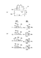
次に本発明の実施の形態を図面を参照して説明する。まず図1を参照して、本実施の形態における部品取出し装置が組み込まれた部品実装装置1の全体構成について説明する。図1において、基台2の上面には、X方向(基板搬送方向)に基板搬送機構3が配設されている。基板搬送機構3は部品実装対象の基板4を上流側装置(図示省略)から受け取ってX方向へ搬送し、以下に説明する部品実装機構による実装作業位置に位置決めして保持する。すなわち基板搬送機構3は基板4を位置決めして保持する基板保持部となっている。   Next, embodiments of the present invention will be described with reference to the drawings. First, with reference to FIG. 1, the entire configuration of a component mounting apparatus 1 in which a component picking-up device according to the present embodiment is incorporated will be described. In FIG. 1, a substrate transfer mechanism 3 is disposed on the upper surface of the base 2 in the X direction (substrate transfer direction). The substrate transfer mechanism 3 receives the substrate 4 to be mounted of components from the upstream apparatus (not shown), transfers it in the X direction, and positions and holds the mounting work position by the component mounting mechanism described below. That is, the substrate transfer mechanism 3 is a substrate holding unit which positions and holds the substrate 4.

基板搬送機構3の一方側の側方には、部品供給部5が配置されている。部品供給部5にはトレイフィーダ6が配置されており、トレイフィーダ6は実装対象の部品8が収納されたトレイ7を、部品実装機構が備えた部品取出しヘッド13による取り出し位置に供給する。トレイ7の上方には第1のカメラ9が撮像方向を下向きにして配設されている。本実施の形態に用いられる部品供給部5が備えたトレイフィーダ6は、一般に用いられるトレイフィーダのように取り出し対象の部品を格子状の規則配列で供給するのではなく、取り出し対象の部品8を不規則な姿勢で供給する形態を採用している。   The component supply unit 5 is disposed on one side of the substrate transfer mechanism 3. A tray feeder 6 is disposed in the component supply unit 5, and the tray feeder 6 supplies the tray 7 in which the component 8 to be mounted is stored to a removal position by a component removal head 13 provided with a component mounting mechanism. Above the tray 7, a first camera 9 is disposed with the imaging direction facing downward. The tray feeder 6 provided in the component supply unit 5 used in the present embodiment does not supply the components to be taken out in a regular grid arrangement like the commonly used tray feeders, but it extracts the components 8 to be taken out. The form which supplies in an irregular attitude is adopted.

基台2のY方向の両端部に配置された1対のフレーム部10の上面にはY軸駆動テーブル11がY方向に配設されており、Y軸駆動テーブル11に架設されたX軸駆動テーブル12には、部品取出しヘッド13がX方向に移動自在に装着されている。Y軸駆動テーブル11、X軸駆動テーブル12はいずれもリニアモータ駆動の直動機構を備えている。Y軸駆動テーブル11、X軸駆動テーブル12を駆動することにより、部品取出しヘッド13はX方向、Y方向に移動し、トレイ7から取り出した部品8を基板搬送機構3に位置決め保持された基板4に移送搭載する。   The Y-axis drive table 11 is disposed in the Y-direction on the upper surface of the pair of frame portions 10 disposed at both ends of the base 2 in the Y-direction. The component pickup head 13 is mounted on the table 12 so as to be movable in the X direction. Each of the Y-axis drive table 11 and the X-axis drive table 12 has a linear motion mechanism driven by a linear motor. By driving the Y-axis drive table 11 and the X-axis drive table 12, the component pick-up head 13 moves in the X and Y directions, and the substrate 4 is positioned and held by the substrate transport mechanism 3 with the component 8 picked from the tray 7. Transfer to

本実施の形態において、Y軸駆動テーブル11、X軸駆動テーブル12および部品取出しヘッド13は、トレイ7から取り出した部品8を搬送する部品搬送部15を構成し、本実施の形態においては部品搬送部15が部品実装機構としての機能を兼務している。すなわち部品取出しヘッド13は、基板4に部品8を移送搭載する実装ヘッドとしての機能を備えている。   In the present embodiment, the Y-axis drive table 11, the X-axis drive table 12, and the component pickup head 13 constitute a component conveyance unit 15 for conveying the component 8 taken out of the tray 7. In the present embodiment, the component conveyance unit The unit 15 doubles as a component mounting mechanism. That is, the component pickup head 13 has a function as a mounting head for transferring and mounting the component 8 on the substrate 4.

トレイ7から部品8を取り出した部品取出しヘッド13が基板4へ移送する移送経路には、第2のカメラ16が配設されている。第2のカメラ16は、部品取出しヘッド13により部品8を基板保持部である基板搬送機構3に保持された基板4に移送する過程において、部品取出しヘッド13によって保持された状態の部品8を下方から撮像する。   A second camera 16 is disposed in a transfer path along which the component pickup head 13 which has taken out the components 8 from the tray 7 transfers to the substrate 4. The second camera 16 lowers the component 8 held by the component pickup head 13 in the process of transferring the component 8 to the substrate 4 held by the substrate transfer mechanism 3 as the substrate holding unit by the component pickup head 13. Image from

図2に示すように、トレイ7の上方に配設された第1のカメラ9によってトレイ7を撮像する(矢印a)ことにより、トレイ7において不規則な姿勢で供給された部品8の画像を取得することができる。すなわち、第1のカメラ9(カメラ)は、部品供給部5によって供給された複数の部品8を撮像する。部品取出しヘッド13は、下面側から下方に延出する複数(ここに示す例では3つ)のチャックユニット14を備えており、チャックユニット14は1対のチャック爪17によって部品8を両側面から挟持して保持する機能を有している。   As shown in FIG. 2, by imaging the tray 7 by the first camera 9 disposed above the tray 7 (arrow a), the image of the parts 8 supplied in an irregular posture in the tray 7 is displayed It can be acquired. That is, the first camera 9 (camera) images the plurality of components 8 supplied by the component supply unit 5. The component pickup head 13 is provided with a plurality of (three in this example) chuck units 14 extending downward from the lower surface side, and the chuck unit 14 has the components 8 from both sides by a pair of chuck claws 17 It has a function to hold and hold.

図3を参照して、チャックユニット14の構成および機能を説明する。図3(a)に示すように、チャックユニット14は本体部14aから上方に延出して部品取出しヘッド13と結合される昇降・回転軸14bを備えている。部品取出しヘッド13に内蔵された昇降機構およびθ回転機構(いずれも図示省略)を駆動することにより、チャックユニット14を昇降させ(矢印c)、さらに昇降・回転軸14b廻りにθ回転(矢印d)させることが可能となっている。   The configuration and function of the chuck unit 14 will be described with reference to FIG. As shown in FIG. 3A, the chuck unit 14 includes an elevating and rotating shaft 14b extending upward from the main body 14a and coupled to the component pickup head 13. The chuck unit 14 is moved up and down (arrow c) by driving the lifting and lowering mechanism and the θ rotating mechanism (all not shown) built in the component pickup head 13 and further theta rotation around the lifting and lowering shaft 14b (arrow d) ) It is possible to

本体部14aには、下方に延出した1対のチャック爪17が、水平な旋回軸17a廻りの旋回が可能に設けられている。本体部14aに内蔵された開閉機構(図示省略)を駆動することにより、1対のチャック爪17は相互に接近・離隔方向に移動し(矢印e)、これにより保持対象の部品を1対のチャック爪17によって挟持して保持することが可能となっている。さらに本体部14aの前面には、押込み機構18が設けられており、押込み機構18から下方に延出した昇降軸18aの下端部には押込み部材18bが結合されている。   The main body portion 14a is provided with a pair of chuck claws 17 extending downward, capable of turning around a horizontal turning shaft 17a. By driving the opening / closing mechanism (not shown) contained in the main body portion 14a, the pair of chuck claws 17 move in the approaching / separating direction from each other (arrow e), thereby holding the parts to be held into a pair It is possible to hold and hold by the chuck claws 17. Further, a pushing mechanism 18 is provided on the front surface of the main body portion 14a, and a pushing member 18b is coupled to a lower end portion of the elevating shaft 18a extending downward from the pushing mechanism 18.

図3(b)に示すように、本体部14aに内蔵された爪旋回機構(図示省略)を駆動することにより、1対のチャック爪17は旋回軸17a廻りに旋回する(矢印f)。これにより、チャックユニット14は水平姿勢で保持した部品8の姿勢を垂直姿勢に変更することができる。また押込み機構18を駆動することにより押込み部材18bが昇降し(矢印g)、これにより、チャック爪17よって垂直姿勢で保持された部品8が押込み部材18bによって押し下げられ、リード8bは基板4の挿入孔4aに挿入される(図14参照)。   As shown in FIG. 3B, by driving a claw pivoting mechanism (not shown) contained in the main body portion 14a, the pair of chuck claws 17 pivot around the pivot shaft 17a (arrow f). Thus, the chuck unit 14 can change the posture of the component 8 held in the horizontal posture to the vertical posture. Further, driving the pushing mechanism 18 raises and lowers the pushing member 18b (arrow g), whereby the component 8 held in the vertical posture by the chuck claw 17 is pushed down by the pushing member 18b and the lead 8b is inserted into the substrate 4 It is inserted in the hole 4a (see FIG. 14).

部品取出しヘッド13によってトレイ7から部品8を取り出す際には、第1のカメラ9による撮像結果を認識処理部19(図5参照)によって認識処理することにより、トレイ7における個別の部品8の位置や姿勢が取得される。そしてこれらの認識結果に基づいて部品取出しヘッド13、チャックユニット14を制御することにより、各チャックユニット14によって部品8を保持して、トレイ7から取り出す(矢印b)ことができる(図12参照)。   When parts 8 are taken out of the tray 7 by the part pickup head 13, the recognition result of the first camera 9 is recognized by the recognition processing unit 19 (see FIG. 5), whereby the positions of the individual parts 8 in the tray 7 are obtained. And posture is acquired. Then, by controlling the component pickup head 13 and the chuck unit 14 based on the recognition results, the components 8 can be held by each chuck unit 14 and taken out from the tray 7 (see arrow b) (see FIG. 12) .

図4に示すように、トレイ7に収納される部品8は、パワートランジスタなど矩形状の部品本体部8aから複数のリード8bが延出した構成のいわゆる挿入部品である。そして基板搬送機構3に位置決め保持された基板4には、リード8bが挿入される挿入孔4aが形成されている。部品8を基板4に実装する際には、各チャックユニット14によって部品8を保持した部品取出しヘッド13が、第2のカメラ16の上方を移動することにより、第2のカメラ16は部品8を下方から撮像する。   As shown in FIG. 4, the component 8 accommodated in the tray 7 is a so-called insert component in which a plurality of leads 8 b extend from a rectangular component body 8 a such as a power transistor. Then, in the substrate 4 positioned and held by the substrate transfer mechanism 3, an insertion hole 4a into which the lead 8b is inserted is formed. When mounting the component 8 on the substrate 4, the second camera 16 moves the component 8 by moving the component pickup head 13 holding the component 8 by each chuck unit 14 above the second camera 16. Take an image from below.

そして第2のカメラ16による撮像結果を認識処理部19(図5参照)によって認識処理することにより、各部品8におけるリード8bの位置が認識される。基板4の上方に移動した部品取出しヘッド13によって部品8を基板4に実装する際には、前述の認識結果に基づいて、リード8bを挿入孔4aに対して位置合わせする(図14参照)。   Then, the recognition processing unit 19 (see FIG. 5) performs recognition processing on the imaging result by the second camera 16 to recognize the position of the lead 8b in each component 8. When the component 8 is mounted on the substrate 4 by the component pickup head 13 moved to the upper side of the substrate 4, the lead 8b is aligned with the insertion hole 4a based on the above-mentioned recognition result (see FIG. 14).

部品8をトレイ7に収納する部品補給作業に際しては、原則として作業者はトレイ7の部品載置面7a上に部品8が相互に重なることなく、1層のみの状態で展開されるよう、部品均しを行う。このとき、トレイ7においては各部品8の方向や表裏は不規則であり、反転状態の部品(符号8*を付している)や2つの部品8が部分的に重なった状態のものが存在する。本実施の形態の部品取り出しにおいては、このような不規則な姿勢で供給される部品8を極力効率よく取り出すために、以下に述べるような構成を用いている。   In the component supply operation for storing the components 8 in the tray 7, in principle, the worker is deployed so that the components 8 are expanded in only one layer without overlapping the components mounting surface 7 a of the tray 7. Do the leveling. At this time, in the tray 7, the direction and the front and back of each component 8 are irregular, and there is a component in a reversed state (indicated by a symbol 8 *) or a state in which two components 8 partially overlap Do. In the component extraction of the present embodiment, in order to extract components 8 supplied in such an irregular posture as efficiently as possible, the configuration described below is used.

ここで図5を参照して、制御系の構成を説明する。図5において、部品実装装置1に内蔵された制御装置20は、図1に示す部品供給部5、部品搬送部15、基板搬送機構3による作業動作を制御する。さらに制御装置20は認識処理部19と接続されており、認識処理部19は第1のカメラ9、第2のカメラ16による撮像結果を認識処理し、認識結果を制御装置20に伝達する。認識処理部19が第1のカメラ9による撮像結果を認識処理することにより、トレイ7における部品8の位置や姿勢が判別される。また認識処理部19は、第2のカメラ16による撮像結果を認識処理することにより、部品取出しヘッド13のチャックユニット14に保持された状態の部品8を認識する。   Here, the configuration of the control system will be described with reference to FIG. In FIG. 5, a control device 20 built in the component mounting apparatus 1 controls work operations by the component supply unit 5, the component conveyance unit 15, and the substrate conveyance mechanism 3 shown in FIG. 1. Furthermore, the control device 20 is connected to the recognition processing unit 19, and the recognition processing unit 19 performs recognition processing of the imaging result by the first camera 9 and the second camera 16, and transmits the recognition result to the control device 20. The recognition processing unit 19 recognizes the imaging result of the first camera 9 to determine the position and orientation of the component 8 in the tray 7. Further, the recognition processing unit 19 recognizes the component 8 in a state of being held by the chuck unit 14 of the component pickup head 13 by performing recognition processing of the imaging result by the second camera 16.

制御装置20は、制御処理部21、プログラム記憶部25、データ記憶部29を備えている。さらに制御処理部21は内部制御機能として実装制御部22、部品検出部23、部品選定部24を備えている。実装制御部22は部品供給部5から取り出された部品8を、基板搬送機構3に位置決め保持された基板4に実装する部品実装動作を制御する。この部品実装動作の制御は、データ記憶部29に記憶された実装データ30を参照しながら、プログラム記憶部25に記憶された実装動作プログラム26を実行することにより行われる。この制御においては、認識処理部19による部品8の認識結果に基づいて前述の部品実装機構を制御して、部品8を基板4に実装する。   The control device 20 includes a control processing unit 21, a program storage unit 25, and a data storage unit 29. The control processing unit 21 further includes a mounting control unit 22, a component detection unit 23, and a component selection unit 24 as an internal control function. The mounting control unit 22 controls a component mounting operation of mounting the component 8 taken out of the component supply unit 5 on the substrate 4 positioned and held by the substrate conveyance mechanism 3. The control of the component mounting operation is performed by executing the mounting operation program 26 stored in the program storage unit 25 while referring to the mounting data 30 stored in the data storage unit 29. In this control, the component mounting mechanism is controlled based on the recognition result of the component 8 by the recognition processing unit 19 to mount the component 8 on the substrate 4.

部品検出部23は、第1のカメラ9により撮像された画像に基づいて、トレイ7に収納された複数の部品8のうち取出し可能な複数の部品8を検出する部品検出処理を行う。この部品検出処理は、データ記憶部29に記憶された取り出し可否判定データ31を参照しながら、プログラム記憶部25に記憶された部品検出処理プログラム27を実行することにより行われる。   The component detection unit 23 performs component detection processing for detecting the plurality of removable components 8 among the plurality of components 8 stored in the tray 7 based on the image captured by the first camera 9. The component detection process is performed by executing the component detection processing program 27 stored in the program storage unit 25 while referring to the removal determination data 31 stored in the data storage unit 29.

部品選定部24は、部品検出部23によって検出された取出し可能な複数の部品8のうち、取出すべき複数の部品8を選定する部品選定処理を行う。この部品選定処理は、データ記憶部29に記憶された部品選定データ32を参照しながら、プログラム記憶部25に記憶された部品選定処理プログラム28を実行することにより行われる。そして部品選定部24によって選定された取出すべき複数の部品8は、部品取出しヘッド13が備えた複数の部品保持部としてのチャックユニット14によって保持されて取り出される。すなわち前述構成の部品搬送部15は、部品選定部24によって選定された取出すべき複数の部品8を複数の部品保持部によってそれぞれ保持して取出す機能を有している。   The component selection unit 24 performs component selection processing for selecting a plurality of components 8 to be extracted among the plurality of removable components 8 detected by the component detection unit 23. The component selection process is performed by executing the component selection processing program 28 stored in the program storage unit 25 while referring to the component selection data 32 stored in the data storage unit 29. The plurality of parts 8 to be taken out selected by the part selecting unit 24 are held and taken out by the chuck units 14 as a plurality of part holding units provided in the part taking out head 13. That is, the component conveyance unit 15 having the above-described configuration has a function of holding and extracting the plurality of components 8 to be taken out selected by the component selection unit 24 by the plurality of component holding units.

本実施の形態においては、部品搬送部15によって取出すべき複数の部品8を取出す過程において、取出すべき複数の部品8を複数の部品保持部としてのチャックユニット14によって同時に保持している状態を必ず経るようにしている。これにより、部品取出しヘッド13の1回の動作によって複数の部品8を取り出すことができ、部品取出しの作業効率を向上させることができる。   In the present embodiment, in the process of taking out the plurality of parts 8 to be taken out by the parts conveyance unit 15, the state of simultaneously holding the plurality of parts 8 to be taken out by the chuck unit 14 as the plurality of part holding units It is like that. Thereby, the plurality of parts 8 can be taken out by one operation of the part taking out head 13, and the working efficiency of the part taking out can be improved.

図5に示す各構成要素のうち、部品実装装置1において部品供給部5から取り出した部品8を基板4に実装するための要素(具体的には、第2のカメラ16、実装制御部22、実装動作プログラム26、実装データ30)を除いた構成要素は、本実施の形態における部品取出し装置を構成する。   Among the components shown in FIG. 5, elements for mounting the component 8 taken out of the component supply unit 5 in the component mounting apparatus 1 on the substrate 4 (specifically, the second camera 16, the mounting control unit 22, The components excluding the mounting operation program 26 and the mounting data 30) constitute a component picking device in the present embodiment.

以下、上述構成の部品取出し装置による部品検出処理において参照される部品基本形状データ31a、部品姿勢データ31b、面識別データ31cおよび重なり判定データ31dについて説明する。   Hereinafter, component basic shape data 31a, component posture data 31b, surface identification data 31c, and overlap determination data 31d, which are referred to in the component detection process by the component extraction device having the above-described configuration, will be described.

図6(a)は、取り出し対象とする部品8の部品基本形状データ31aを示している。すなわち部品基本形状データ31aには、部品8を構成する部品本体部8aの平面寸法A、B、リード8bの幅b、リード長さlおよびリードピッチpが示されている。部品基本形状データ31aを参照することにより、部品取出しヘッド13が備えたチャックユニット14によって当該部品8を保持することが可能であるか否かが、寸法・形状面から判断される。   FIG. 6A shows component basic shape data 31 a of the component 8 to be taken out. That is, in the component basic shape data 31a, planar dimensions A and B of the component body 8a constituting the component 8, the width b of the lead 8b, the lead length l and the lead pitch p are shown. By referring to the part basic shape data 31a, whether or not the part 8 can be held by the chuck unit 14 provided in the part pickup head 13 is determined from the size and shape.

図6(b)に示す部品姿勢データ31bでは、当該部品8がトレイ7の部品載置面7aに平面的に載置された状態における基本的な姿勢パターンと、それぞれの姿勢パターンに対応する認識画像、すなわち第1のカメラ9によって取得される画像との対応が示されている。まず図6(b)(1)は、部品本体部8aが部品載置面7aに完全に接触し、表面8cが水平な状態で載置された部品姿勢を示している。この状態では、第1のカメラ9による認識画像では、表面8c、リード8bの形状そのままが現れる。図6(b)(2)は、部品本体部8aが部品載置面7a上で傾いた状態となって、リード8bの先端が部品載置面7aに接触した部品姿勢を示している。この状態では、認識画像において表面8c、リード8bが傾斜した状態の形状が現れる。   In the component posture data 31b shown in FIG. 6 (b), a basic posture pattern in a state where the component 8 is placed flatly on the component mounting surface 7a of the tray 7, and recognition corresponding to each posture pattern The correspondence with the image, i.e. the image acquired by the first camera 9 is shown. First, FIGS. 6 (b) and 6 (1) show the component posture in which the component body 8a is completely in contact with the component placement surface 7a and the surface 8c is placed horizontally. In this state, in the image recognized by the first camera 9, the shapes of the surface 8c and the leads 8b appear as they are. 6 (b) and 6 (2) show the component posture in which the tip of the lead 8b contacts the component placement surface 7a with the component body 8a inclining on the component placement surface 7a. In this state, the shape in which the surface 8c and the lead 8b are inclined appears in the recognition image.

図6(b)(3)、図6(b)(4)は、部品8が表裏反転した状態で部品載置面7aに載置された姿勢を示しており、それぞれ図6(b)(1)、図6(b)(2)に示す状態に対応している。図6(b)(3)は、部品本体部8aが裏面8dを上向きにして部品載置面7aに完全に接触した状態で載置された部品姿勢を示している。この状態では、第1のカメラ9による認識画像では、裏面8d、リード8bの形状そのままが現れる。図6(b)(4)は、部品本体部8aが裏面8dを上向きにして部品載置面7a上で傾いた状態となって、リード8bの先端が部品載置面7aに接触した部品姿勢を示している。この状態では、認識画像において裏面8d、リード8bが傾斜した状態の形状が現れる。   6 (b) (3) and 6 (b) (4) show the posture in which the component 8 is placed on the component placement surface 7a in a state of being turned upside down, respectively, and FIG. 1) corresponds to the state shown in FIG. 6 (b) (2). FIGS. 6 (b) and 6 (3) show the posture of the component placed with the component body 8a completely in contact with the component placement surface 7a with the back surface 8d facing upward. In this state, in the image recognized by the first camera 9, the shapes of the back surface 8d and the leads 8b appear as they are. In FIGS. 6B and 6C, the component body 8a is inclined on the component placement surface 7a with the back surface 8d facing upward, and the component posture in which the tip of the lead 8b contacts the component placement surface 7a Is shown. In this state, in the recognition image, the shape of the state in which the back surface 8d and the lead 8b are inclined appears.

このような部品姿勢データ31bを予め準備して記憶させておくことにより、第1のカメラ9によって撮像した認識結果に基づいて、実際の部品8の姿勢を判断することができ、取り出しが可能か否かを高い精度で判断することができる。なお図6(b)に示す例は部品姿勢の例示であり、これら以外にも対象とする部品種類や形状の特徴に応じて種々の姿勢パターンを設定することが可能である。   By preparing and storing such component posture data 31b in advance, it is possible to determine the actual posture of the component 8 based on the recognition result captured by the first camera 9, and it is possible to take it out It can be judged with high accuracy whether or not. The example shown in FIG. 6B is an example of the component posture, and various posture patterns can be set according to the feature type and shape of the component other than the above.

また図6(b)に示す部品8の画像を参照することにより、当該部品8が表面8c、裏面8dのいずれを上面側にして載置されているかを識別することができる。したがって図6(b)に示すデータは、部品8の表裏面を識別する面識別データとなっている。   Further, by referring to the image of the component 8 shown in FIG. 6 (b), it can be identified which of the surface 8c and the back surface 8d is placed with the upper surface side. Therefore, the data shown in FIG. 6B is surface identification data for identifying the front and back surfaces of the component 8.

次に図7を参照して、重なり判定データ31dについて説明する。前述のように、部品8は原則として作業者はトレイ7の部品載置面7a上に相互に重なることなく1層のみの状態となるように均しながら載置される。しかしながら部品ならし作業は必ずしも完全であるとは限らず、部分的に部品相互が重なった状態となっている場合が生じる。このとき部品相互が重なった全ての部品が取り出し対象から排除されるわけではなく、重なり状態によっては部品取り出しの対象とすることができる場合が存在する。重なり判定データ31dはこのような部品取り出し可否を判定する際に参照される参考データである。   Next, the overlap determination data 31d will be described with reference to FIG. As described above, the components 8 are, in principle, mounted with leveling so that the worker is in the state of only one layer without overlapping each other on the component mounting surface 7 a of the tray 7. However, the part leveling operation is not always perfect, and there are cases where parts are partially overlapped with each other. At this time, not all parts in which parts overlap with each other are not excluded from the objects to be taken out, and there are cases where depending on the overlapping state, the parts can be taken out as parts. The overlap determination data 31 d is reference data to be referred to when determining whether such a part can be taken out.

まず図7(a)に示す例は、トレイ7の部品載置面7aに供給された部品8のうち、他の部品(8)が部分的に重なった場合にあっても、部品取出しが可能な例を示している。すなわち、図7(a)(1)では、図6(b)(1)に示す状態の部品8において、リード8bに部分的に他の部品(部品(8)と記載して取り出し対象の部品8と区別する)の部品本体部8aが重なった状態を示している。このとき、部品8においてチャックユニット14のチャック爪17による挟持面である挟持側面8eがフリーであれば、部品8を取り出すことができる場合がある。   First, in the example shown in FIG. 7A, even if another part (8) of the parts 8 supplied to the parts mounting surface 7a of the tray 7 partially overlaps, parts can be taken out. An example is shown. That is, in FIG. 7 (a) (1), in the component 8 in the state shown in FIG. 6 (b) (1), the lead 8 b is partially described as another component (component (8)) and the component to be taken out 8 shows a state in which the component body portions 8a of 8) are overlapped. At this time, if the sandwiching side surface 8e which is the sandwiching surface of the chuck unit 14 of the chuck unit 14 in the component 8 is free, the component 8 may be able to be taken out.

同様に 図7(a)(2)は、図6(b)(3)に示す状態の部品8において、リード8bに部分的に他の部品(8)の部品本体部8aが重なった状態を示している。この場合においても、チャック爪17による挟持側面8eがフリーであれば部品8を取り出すことができる場合がある。また図7(a)(3)は、図6(b)(1)に示す状態の部品8において、リード8bに部分的に他の部品(8)のリード8bが重なった状態を示している。この場合においても、チャック爪17による挟持側面8eがフリーであれば部品8を取り出すことができる場合がある。このように、図7(a)に示すような状態の場合には、部品検出部23は当該部品8は取り出し可能であると判断する。   Similarly, in FIGS. 7 (a) and 7 (2), in the component 8 shown in FIGS. 6 (b) and 6 (3), the lead 8b is partially overlapped with the component body 8a of another component (8). It shows. Also in this case, if the clamping side surface 8e by the chuck claw 17 is free, the component 8 may be able to be taken out. 7 (a) and 7 (3) show a state in which the lead 8b of another part (8) partially overlaps the lead 8b in the part 8 shown in FIGS. 6 (b) and 6 (1). . Also in this case, if the clamping side surface 8e by the chuck claw 17 is free, the component 8 may be able to be taken out. As described above, in the state as shown in FIG. 7A, the component detection unit 23 determines that the component 8 can be taken out.

すなわち、部品検出部23は、部品供給部5によって供給された複数の部品8のうち、少なくとも一部が他の部品(8)によって隠蔽されていない複数の部品8を、取出し可能な複数の部品8として検出する。なお、ここでは部品保持部としてチャック爪17によって部品8を挟持するチャックユニット14を用いる例を示しているが、部品保持部として吸着ノズルによって部品8を吸着保持する構成のノズルユニット(例えば図15、図16に示すノズルユニット40)を用いる場合には、部品8が取り出し可能であるためには吸着ノズルによる吸着面が露呈されていれば足りる場合が多いことから、少なくとも一部が他の部品(8)によって隠蔽されていない部品8が取出し可能な部品8であると判定される確率が高くなる。   That is, the component detection unit 23 can extract a plurality of components 8 among the plurality of components 8 supplied by the component supply unit 5, at least a part of which can not be concealed by another component (8). Detect as 8 Here, although an example using the chuck unit 14 for holding the component 8 by the chuck claws 17 as the component holding unit is shown, a nozzle unit configured to suction and hold the component 8 by the suction nozzle as the component holding unit (for example, FIG. 15) When the nozzle unit 40) shown in FIG. 16 is used, it is often sufficient if the suction surface by the suction nozzle is exposed in order for the component 8 to be removable, so at least a part of other components The probability that the part 8 not concealed by (8) is determined to be the removable part 8 increases.

またこの取り出し可否の判断に際し、上述のように、少なくとも一部が他の部品によって隠蔽されていなく、且つ部品8において第1のカメラ9側に向いた面が同一の面(表面8cまたは裏面8d)であるような複数の部品8を、取り出し可能な部品8として検出するようにしてもよい。すなわちこの場合には、重なり判定データ31dと、面識別データ31cとを組み合わせて取り出し可否判定を行う形態となる。   In addition, at the time of determining whether or not the removal is possible, as described above, at least a part is not concealed by another component, and the surface of component 8 facing the first camera 9 is the same surface (front surface 8c or back surface 8d The plurality of parts 8 may be detected as the removable parts 8. That is, in this case, the overlap determination data 31 d and the surface identification data 31 c are combined to perform the extraction determination.

これに対し、図7(b)は、トレイ7の部品載置面7aに供給された部品8のうち、他の部品(8)が部分的に重なった場合において、部品取出しが不可能な例を示している。すなわち、図7(b)(1)(2)では、いずれも図6(b)(1)に示す状態の部品8において、部品本体部8aに部分的に他の部品(8)の部品本体部8aが重なった状態を示している。   On the other hand, FIG. 7 (b) shows an example in which the component can not be taken out when the other component (8) of the components 8 supplied to the component mounting surface 7a of the tray 7 partially overlaps. Is shown. That is, in FIG. 7 (b) (1) (2), in the part 8 in the state shown in FIG. 6 (b) (1), the component body of another component (8) partially in the component body 8a. It shows a state in which the parts 8a overlap.

この状態では、チャックユニット14のチャック爪17による挟持側面8eが他の部品(8)によって隠蔽されており、チャック爪17による部品8の挟持が不可能であるため、部品8を取り出すことができない。換言すれば、部品検出部23は、取り出し対象とする部品8において、チャックユニット14のチャック爪17による挟持側面8eが他の部品(8)によって隠蔽されているか否かを判断することにより、部品取り出しの可否を判定する。   In this state, the pinching side surface 8e of the chuck unit 14 of the chuck unit 14 is covered by the other component (8), and the component 8 can not be gripped by the chuck jaw 17, so the component 8 can not be taken out. . In other words, in the component 8 to be taken out, the component detection unit 23 determines whether the clamping side surface 8e of the chuck unit 14 of the chuck unit 14 is covered by another component (8). Determine whether or not to take out.

次に、部品選定部24が部品選定処理プログラム28を実行することによって実行される部品選定処理について説明する。本実施の形態では、この部品選定処理において、第1モード28a、第2モード28b、第3モード28c、第4モード28d、第5モード28eの複数のモードを、単独でまたは組み合わせて実行するようにしている。これらの複数のモードの実行に際しては、部品選定データ32に記憶されたデータが参照される。   Next, the component selection processing executed by the component selection unit 24 executing the component selection processing program 28 will be described. In this embodiment, in the component selection process, a plurality of modes, that is, the first mode 28a, the second mode 28b, the third mode 28c, the fourth mode 28d, and the fifth mode 28e, may be executed alone or in combination. I have to. The data stored in the part selection data 32 is referred to when executing the plurality of modes.

まず図8に示す取出し領域データ32aを参照して実行される第1モード28a(領域限定)について説明する。第1モード28aでは、部品選定部24は部品検出部23によって検出された取出し可能な複数の部品8のうち、特定領域に存在する部品を、取出すべき複数の部品8として選定する。ここで特定領域とは、取り出し対象となる領域であるトレイ7を何らかの規則によって分割した領域であり、ここで用いる規則は適宜設定することができる。   First, the first mode 28a (area limitation) executed with reference to the extraction area data 32a shown in FIG. 8 will be described. In the first mode 28 a, the component selection unit 24 selects a component present in a specific area among the plurality of removable components 8 detected by the component detection unit 23 as the plurality of components 8 to be extracted. Here, the specific area is an area obtained by dividing the tray 7 which is an area to be taken out according to a certain rule, and the rule used here can be set as appropriate.

例えば図8(a)に示すように、取り出し対象の部品8が不規則な姿勢で供給されたトレイ7において、トレイ7内の領域を幾何学的な規則(例えば象限分割)に基づいて、第1領域R1〜第4領域R4に分割して特定された領域であってもよい。また図8(b)に示すように、取り出し可能な姿勢の部品8が集中していると判断される領域R11、R12、R13を目視などによって見出し、認識処理部19を介して領域入力することにより特定領域を定義するようにしてもよい。   For example, as shown in FIG. 8A, in the tray 7 to which the parts 8 to be taken out are supplied in an irregular posture, the area in the tray 7 is divided on the basis of geometric rules (for example, quadrant division). It may be a region specified by being divided into the first region R1 to the fourth region R4. Further, as shown in FIG. 8B, the regions R11, R12, and R13 where it is determined that the component 8 in the removable posture is concentrated are visually found and the region input is performed through the recognition processing unit 19. The specific area may be defined by

次に図9に示す移動距離・時間算定データ32bを参照して、第2モード28b(移動距離最小)、第3モード28c(移動時間最短)について説明する。ここでは、部品取出しヘッド13が備えた複数(ここでは3つ)のそれぞれに部品8を保持させて取り出す部品取出し動作における部品搬送部15による部品取出しヘッド13の移動距離、または移動時間に基づいて、取り出すべき複数の部品を選定する例を示している。   Next, the second mode 28b (minimum movement distance) and the third mode 28c (minimum movement time) will be described with reference to movement distance / time calculation data 32b shown in FIG. Here, based on the movement distance or movement time of the component pickup head 13 by the component conveyance unit 15 in the component pickup operation in which the plurality of (here, three) components 8 held by the component pickup head 13 are held and taken out. , Shows an example of selecting a plurality of parts to be taken out.

まず図9(a)を参照して、部品取出し動作における部品取出しヘッド13の移動距離に基づいて、より具体的には部品取出しヘッド13の移動距離が最短となるように、取出すべき複数の部品を選定する例について説明する。図9(a)は、トレイ7によって供給される複数の取り出し対象の部品8のうち、部品8(1)、(2)、(3)(ハッチングにて示す)を、3つのチャックユニット14(1)、(2)、(3)によって順次取り出す取り出し対象と仮定した場合の部品取出しヘッド13の移動経路および移動距離を示している。   First, referring to FIG. 9A, a plurality of parts to be extracted based on the movement distance of the part extraction head 13 in the part extraction operation, more specifically, the movement distance of the part extraction head 13 is shortest. An example of selecting will be described. FIG. 9A shows three chuck units 14 (indicated by hatching) among the parts 8 (1), (2), and (3) (indicated by hatching) among the parts 8 to be taken out supplied by the tray 7. 1), (2), and (3) show the movement path and movement distance of the component pickup head 13 when it is assumed that the object is to be taken out sequentially.

図9(a)においてヘッド中心HCは部品取出しヘッド13の中心位置を示しており、チャック中心C(1)、(2)、(3)は、チャックユニット14(1)、(2)、(3)による部品保持位置の中心点をそれぞれ示している。部品取り出し動作が開始されると、まずチャックユニット14(1)によって部品8(1)を保持すべく、チャック中心C(1)を移動させて(矢印i)部品8(1)の上方に位置させるために、ヘッド中心HCをヘッド中心HC1に移動させる(矢印h)。   In FIG. 9A, the head center HC indicates the center position of the component pickup head 13, and the chuck centers C (1), (2), (3) indicate the chuck units 14 (1), (2), ( The center point of the component holding position according to 3) is shown. When the component removal operation is started, first, the chuck center C (1) is moved to hold the component 8 (1) by the chuck unit 14 (1) (arrow i) above the component 8 (1) In order to cause the head center HC to move to the head center HC1 (arrow h).

このときの部品取出しヘッド13の移動距離はD1である。次いで、チャックユニット14(2)によって部品8(2)を保持すべく、チャック中心C(2)を移動させて(矢印k)部品8(2)の上方に位置させるために、ヘッド中心HCをヘッド中心HC1からヘッド中心HC2に移動させる(矢印j)。このときの部品取出しヘッド13の移動距離はD2である。   The moving distance of the component pickup head 13 at this time is D1. Then, to hold the part 8 (2) by the chuck unit 14 (2), move the chuck center C (2) (arrow k) to position the head center HC above the part 8 (2) The head center HC1 is moved to the head center HC2 (arrow j). The moving distance of the component pickup head 13 at this time is D2.

さらに、チャックユニット14(3)によって部品8(3)を保持すべく、チャック中心C(3)を移動させて(矢印m)部品8(3)の上方に位置させるために、ヘッド中心HCをヘッド中心HC2からヘッド中心HC3に移動させる(矢印l)。このときの部品取出しヘッド13の移動距離はD3である。これにより、複数の取り出し可能な部品8のうち、部品8(1)、(2)、(3)を取り出し対象とした場合の部品取出しヘッド13の合計移動距離ΣD=D1+D2+D3が演算により求められる。   Furthermore, in order to hold the component 8 (3) by the chuck unit 14 (3), the head center HC is moved to move the chuck center C (3) to position it above the component 8 (3) (arrow m). The head center HC2 is moved to the head center HC3 (arrow l). The moving distance of the component pickup head 13 at this time is D3. Thus, the total movement distance 取 り 出 し D = D1 + D2 + D3 of the component pickup head 13 in the case where the components 8 (1), (2) and (3) are to be extracted among the plurality of removable components 8 is obtained by calculation.

この移動距離演算を取り出し可能な複数の部品8の全ての組み合わせについて実行することにより、最小の合計移動距離ΣDを与える部品8の組み合わせが求められ,この組み合わせによって与えられる複数の部品8が、部品取出しヘッド13の移動距離が最短となる複数の部品8となる。   By executing this movement distance calculation for all combinations of a plurality of extractable parts 8, a combination of parts 8 giving a minimum total movement distance DD is determined, and the plurality of parts 8 given by this combination are parts The plurality of parts 8 in which the moving distance of the pickup head 13 is the shortest are obtained.

次に図9(b)を参照して、部品取出し動作における部品取出しヘッド13の移動時間に基づいて、より具体的には部品取出しヘッド13の移動時間が最短となるように、取出すべき複数の部品を選定する例について説明する。図9(b)は、1つの取出し対象の部品8から次の取出し対象の部品8まで部品取出しヘッド13が移動する際の移動速度の時間変化を示す速度パターンを図示している。   Next, referring to FIG. 9 (b), based on the movement time of the component pickup head 13 in the component pickup operation, more specifically, the movement time of the component pickup head 13 should be minimized. An example of selecting parts will be described. FIG. 9 (b) illustrates a velocity pattern indicating a temporal change in moving speed when the component pickup head 13 moves from one component 8 to be extracted to the next component 8 to be extracted.

この部品取出しヘッド13の移動では、略台形状の速度パターンで速度Vが変化し、台形内の面積(ハッチング部参照)が所定の移動距離Diに相当する。すなわち停止状態から予め設定された加速度α1で加速して規定の最高速度VMに到達すると一定速度で移動し、停止位置に到達する手前で予め設定された制動加速度α2で減速を開始し、移動開始から移動距離Diだけ移動した後に停止する。   In the movement of the component pickup head 13, the velocity V changes in a substantially trapezoidal velocity pattern, and the area within the trapezoid (see the hatched portion) corresponds to the predetermined movement distance Di. That is, it accelerates with a preset acceleration α1 from a stop state and moves at a constant speed when reaching a prescribed maximum velocity VM, starts deceleration with a braking acceleration α2 set in advance before reaching a stop position, and starts moving Stop after moving by the moving distance Di from.

この停止動作に際しては、駆動サーボ系からのフィードバックパルスが、指令された移動距離Diに相当するパルス数に収束するまでに必要とされる整定時間TSだけ、完全停止タイミングが遅延する。すなわち、部品取出しヘッド13が1つの取出し対象の部品8から次の取出し対象の部品8まで移動する単位移動動作に要する移動時間Tiは、必ずしも移動距離Diとは比例しない。換言すれば、部品取出しヘッド13による複数の部品8の取り出し動作における所要時間、すなわち部品取出しヘッド13の単位移動動作における合計移動時間ΣTiは、取り出し対象となる部品8の組み合わせによって異なる。   In this stop operation, the complete stop timing is delayed by the settling time TS required for the feedback pulse from the drive servo system to converge on the number of pulses corresponding to the instructed movement distance Di. That is, the moving time Ti required for the unit moving operation in which the component pickup head 13 moves from one component 8 to be extracted to the next component 8 to be extracted is not necessarily proportional to the moving distance Di. In other words, the required time for the removal operation of the plurality of parts 8 by the part removal head 13, that is, the total movement time TiTi in unit movement operation of the part removal head 13 differs depending on the combination of the parts 8 to be removed.

したがって、複数の取り出し可能な部品8のうち、特定の3つの部品8を取り出し対象とした場合の部品取出しヘッド13の合計移動時間ΣTiが演算により求められる。この移動時間演算を取り出し可能な複数の部品8の全ての組み合わせについて実行することにより、最短時間のΣTiを与える部品8の組み合わせが求められ,この組み合わせによって与えられる複数の部品8が、部品取出しヘッド13の移動時間が最短となる複数の部品8となる。   Therefore, the total movement time TiTi of the component pickup head 13 in the case where the specific three components 8 are to be extracted among the plurality of removable components 8 is obtained by calculation. By executing this movement time calculation for all combinations of a plurality of extractable parts 8, a combination of parts 8 giving the shortest time Σ Ti can be determined, and a plurality of parts 8 given by this combination are the part extraction head A plurality of parts 8 with the shortest movement time of 13 are obtained.

次に図10に示す部品方向データ32cを参照して実行される第4モード28d(部品方向限定)について説明する。トレイ7に収納された複数の部品8のうち部品検出部23によって取り出し可能であると判断されたものの中には、部品の向きがランダムに異なるものが多数存在する。ここで部品の向きとは、図10(a)に示すように、部品8の部品本体部8aの長手方向を示す基準線8g(部品本体部8aの中心点8fを通り部品本体部8aの長手方向に平行な直線)が、トレイ7における基準方向(ここではX方向)に対してなす角度θで表される。   Next, the fourth mode 28 d (part direction limitation) executed with reference to the part direction data 32 c shown in FIG. 10 will be described. Among the plurality of components 8 stored in the tray 7, among those determined to be removable by the component detection unit 23, there are many components whose orientations are randomly different. Here, as shown in FIG. 10 (a), the orientation of the component is a reference line 8g indicating the longitudinal direction of the component body 8a of the component 8 (the center point 8f of the component body 8a passes through the component body 8a A straight line parallel to the direction is represented by an angle θ formed with respect to a reference direction (here, the X direction) in the tray 7.

部品実装動作に際しては、実装データによって予め規定された実装方向に部品の向きを合わせる回転位置補正が必要とされるため、トレイ7から部品8を取り出す時点においてこれらの部品の向きが大幅に異なっていると、回転位置補正時に必要とされる回転補正量が大きくなる。この回転位置補正量が大きい場合には、回転位置補正に時間を要して実装動作効率を低下させる。   In the component mounting operation, rotational position correction is required to align the components in the mounting direction defined in advance by the mounting data. Therefore, the orientations of these components are significantly different at the time of removing the components 8 from the tray 7 In this case, the amount of rotation correction required at the time of rotational position correction becomes large. When the rotational position correction amount is large, it takes time for the rotational position correction to lower the mounting operation efficiency.

この効率の低下を防止するために回転位置補正時の回転速度を大きくすると、回転動作の加減速時に部品8に作用する慣性力による部品8の不安定を招く。特に、部品取出しヘッド13に装着される部品保持部として真空吸着によって部品8を保持する吸着ノズルを用いる場合(図15、図16参照)には、吸着ノズルの保持面に滑りが生じやすく、この慣性力による位置ずれなどの不具合が大きくなる。   If the rotational speed at the time of rotational position correction is increased in order to prevent the decrease in efficiency, instability of the component 8 is caused by the inertial force acting on the component 8 at the time of acceleration / deceleration of rotational operation. In particular, in the case where a suction nozzle holding the component 8 by vacuum suction is used as a component holding unit mounted on the component pickup head 13 (see FIGS. 15 and 16), the holding surface of the suction nozzle tends to slip. Problems such as misalignment due to inertial force increase.

このような回転位置補正時の不具合を極力防止するため、本実施の形態に示す部品取り出しでは、図10(b)に示すように、部品種類Pa、Pb、Pc・・・のそれぞれに応じて、取出し可能角度範囲θa、θb、θc・・・を予め設定しておき、図10(a)に示す部品の向き、すなわち角度θが取出し可能角度範囲θa、θb、θc・・・を上限とする取出し可能角度範囲以内であるもののみを取り出し対象の部品8とするようにしている。すなわち、部品選定部24は、部品検出部23によって検出された取出し可能な複数の部品8のうち、部品8の向きが所定範囲以内である複数の部品8を、取出すべき複数の部品8として選定するようにしている。   In order to prevent such a defect at the time of rotational position correction as much as possible, in the component extraction shown in the present embodiment, as shown in FIG. 10B, according to each of component types Pa, Pb, Pc,. Are set in advance, and the orientations of the parts shown in FIG. 10A, that is, the angle θ is an upper limit of the extractable angular ranges θa, θb, θc,. Only the parts within the removable angle range to be taken out are taken as the parts 8 to be taken out. That is, among the plurality of removable components 8 detected by the component detection unit 23, the component selection unit 24 selects, as the plurality of components 8 to be extracted, a plurality of components 8 in which the direction of the component 8 is within a predetermined range. I am trying to do it.

次に第5モード28e(取出し面限定)について説明する。この部品取出しモードでは、トレイ7に不規則な姿勢で収納された複数の部品8のうち、第1のカメラ9に向いた面が同一面である部品8のみを取出し対象とするようにしている。ここでは図6(b)に示す面識別データ31cが参照され、表面8cが上面となっている部品8のみ、または裏面8dが上面となっている部品8のみを取出し対象とする。すなわちこの場合には、部品選定部24は、部品検出部23によって検出された取出し可能な複数の部品8のうち、第1のカメラ9側に向いた面が同一面である複数の部品8を取出すべき複数の部品8として選定するようにしている。   Next, the fifth mode 28 e (extraction surface limitation) will be described. In this component removal mode, among the plurality of components 8 stored in the tray 7 in an irregular posture, only the component 8 having the same surface facing the first camera 9 is to be removed. . Here, the surface identification data 31c shown in FIG. 6B is referred to, and only the component 8 whose front surface 8c is the upper surface or only the component 8 whose rear surface 8d is the upper surface are taken out. That is, in this case, the component selection unit 24 selects the plurality of components 8 having the same surface facing the first camera 9 among the plurality of removable components 8 detected by the component detection unit 23. The plurality of parts 8 to be taken out are selected.

本実施の形態の部品取出し装置が組み込まれた部品実装装置1は上記のように構成されており、以下部品実装装置1によって実行される部品実装動作について、図11のフローに則して各図を参照して説明する。ここに示す部品実装動作においては、部品取出し装置による部品取り出し方法が用いられている。   The component mounting apparatus 1 in which the component picking-up device of the present embodiment is incorporated is configured as described above, and the component mounting operation performed by the component mounting apparatus 1 will be described based on the flow of FIG. Explain with reference to. In the component mounting operation shown here, a component picking method using a component picking device is used.

部品供給部5において、トレイ7上で部品取出しヘッド13による取り出し対象となる複数の部品8を不規則な姿勢で供給する(部品供給工程)(ST1)。ここでは、予め複数の部品8が不規則な姿勢で収容されたトレイ7を、トレイフィーダ6によって部品取出しヘッド13による部品取出し位置に供給する。次いで、供給された複数の部品8を第1のカメラ9で撮像する(撮像工程)(ST2)。   The component supply unit 5 supplies a plurality of components 8 to be picked up by the component pickup head 13 on the tray 7 in an irregular posture (component supply process) (ST1). Here, the tray 7 in which a plurality of components 8 are accommodated in an irregular posture in advance is supplied by the tray feeder 6 to the component pickup position by the component pickup head 13. Next, the plurality of parts 8 supplied are imaged by the first camera 9 (imaging step) (ST2).

そして撮像された画像に基づいて、部品検出部23によって取り出し可能な部品8を検出する(部品検出工程)(ST3)。すなわち、撮像された画像を認識処理部19によって認識処理した結果に基づき、部品検出部23が部品検出処理プログラム27を実行して前述の取り出し可否判定データ31を参照することにより、個別の部品8が取り出し可能であるか否かを判断する。   Then, based on the captured image, the component detection unit 23 detects the removable component 8 (component detection step) (ST3). That is, the component detection unit 23 executes the component detection processing program 27 based on the result of the recognition processing of the captured image by the recognition processing unit 19 and refers to the above-mentioned removal determination data 31, thereby individual components 8. Determines whether it is possible to take out.

次いで検出された取り出し可能な部品のうち取り出すべき複数の部品を選定する(部品選定工程)(ST4)。すなわち、部品検出工程において部品検出部23によって取り出し可能であると判断された部品8を対象として、部品選定部24が部品選定処理プログラム28を実行して部品選定データ32を参照することにより、取り出すべき複数の部品を選定する。   Next, a plurality of parts to be taken out of the detected removable parts are selected (part selection process) (ST4). That is, the component selection unit 24 executes the component selection processing program 28 and refers to the component selection data 32 for the component 8 determined to be removable by the component detection unit 23 in the component detection process. Select multiple parts to be done.

この部品の選定では、以下に述べる部品搬送工程での部品取出し動作における移動距離または移動時間に基づいて、取出すべき複数の部品8を選定するパターンや、取り出し可能な複数の部品8のうち、部品の向きが所定範囲以内である複数の部品8を取出すべき複数の部品8として選定するパターンなど、種々のパターンを適用することができる。   In this selection of parts, a pattern for selecting a plurality of parts 8 to be taken out based on the movement distance or movement time in the part picking operation in the part conveyance process described below, or a part among a plurality of parts 8 which can be taken out Various patterns can be applied such as a pattern for selecting a plurality of parts 8 whose orientation is within a predetermined range as the plurality of parts 8 to be taken out.

そして選定された複数の部品8を複数の部品保持部であるチャックユニット14によってそれぞれ保持して取り出す(部品搬送工程)(ST5)。図12は、チャックユニット14による部品取り出し動作を示している。すなわち図12(a)に示すように、チャック爪17が開状態で、押込み部材18bが上昇位置にあるチャックユニット14を、トレイ7の部品載置面7a上に位置する部品8の上方へ移動させ、部品8に対して下降させる(矢印n)。   Then, the plurality of selected components 8 are respectively held and taken out by the chuck units 14 which are a plurality of component holding units (component conveyance process) (ST5). FIG. 12 shows the component removal operation by the chuck unit 14. That is, as shown in FIG. 12A, the chuck unit 17 with the push-in member 18b in the raised position with the chuck claw 17 in the open state is moved above the component 8 located on the component mounting surface 7a of the tray 7. And lower the component 8 (arrow n).

ここでは、部品8は部品本体部8aの表面8cを上に向けた姿勢で部品載置面7a上に載置されており、部品本体部8aの両側面の挟持側面8eはフリーな状態となっている。チャックユニット14を部品8に対して下降させる過程では、チャック爪17によって挟持側面8eを挟持可能なように位置合わせが行われる。そしてこの状態でチャックユニット14を部品8に対して下降させて、チャック爪17に閉動作を行わせることにより、図12(b)に示すように、チャックユニット14はチャック爪17によって部品本体部8aの挟持側面8eを両側から挟持する。これにより、チャックユニット14による部品8の保持が完了する。   Here, the component 8 is placed on the component placement surface 7a with the surface 8c of the component body 8a facing upward, and the sandwiching side surfaces 8e on both sides of the component body 8a are free. ing. In the process of lowering the chuck unit 14 with respect to the component 8, alignment is performed so that the clamping side surface 8 e can be pinched by the chuck claws 17. Then, in this state, the chuck unit 14 is lowered relative to the component 8 to cause the chuck claw 17 to perform a closing operation, whereby the chuck unit 14 is moved by the chuck claw 17 as shown in FIG. The sandwiching side surface 8e of 8a is clamped from both sides. Thus, the holding of the component 8 by the chuck unit 14 is completed.

そしてこの状態のチャックユニット14を上昇させて、取出し方向へ移動させる(矢印o)。この過程において、チャック爪17を時計回り方向に90度旋回させることにより、チャック爪17によって挟持された部品8は、リード8bを下方に向けた姿勢に姿勢変換される。そしてこれにより、部品取出しヘッド13に設けられた1つのチャックユニット14による部品8の取り出しが終了する。   Then, the chuck unit 14 in this state is raised and moved in the removal direction (arrow o). In this process, by turning the chuck claw 17 clockwise by 90 degrees, the component 8 nipped by the chuck claw 17 is converted into a posture in which the lead 8 b is directed downward. Then, the removal of the part 8 by one chuck unit 14 provided in the part removal head 13 is completed.

この部品取り出し動作は部品取出しヘッド13に設けられた複数(ここでは3つ)のチャックユニット14について順次実行され、これにより、図13(a)に示すように、部品取出しヘッド13に設けられた3つのチャックユニット14(1)、(2)、(3)のそれぞれに、部品8をリード8bを下方に向けた姿勢で保持した状態となる。すなわち本実施の形態に示す部品取出し装置では、部品搬送工程にて、部品搬送部15によって取出すべき複数の部品8を取出す過程において、取出すべき複数の部品8を複数の部品保持部であるチャックユニット14(1)、(2)、(3)によって同時に保持している状態を経る形態となっている。   The component picking operation is sequentially performed on a plurality of (here, three) chuck units 14 provided in the component picking head 13, whereby the component picking head 13 is provided with the component picking head 13 as shown in FIG. In each of the three chuck units 14 (1), (2) and (3), the component 8 is held in a posture in which the lead 8b is directed downward. That is, in the component pick-up device shown in the present embodiment, in the component feeding step, in the step of picking up the plurality of components 8 to be picked up by the component feeding unit 15, the chuck unit is a plurality of component holding portions. 14 (1), (2), and (3) are in the form of passing through the state of being simultaneously held.

この後、取り出した部品8を保持したチャックユニット14を、第2のカメラ16の上方に移動させる(ST6)。すなわち図13(b)に示すように、チャックユニット14(1)、(2)、(3)のそれぞれに部品8を保持した部品取出しヘッド13を第2のカメラ16の上方に移動させ、第2のカメラ16によって、それぞれのチャックユニット14(1)、(2)、(3)に保持された部品8を下方から撮像する(ST7)。次いで撮像された画像に基づいて部品8の位置ずれを認識する(ST8)。すなわち、撮像結果を認識処理部19によって認識処理することにより、保持された部品8のリード8bの本来位置すべき正規位置に対する位置ずれをそれぞれ認識する。   Thereafter, the chuck unit 14 holding the taken-out component 8 is moved above the second camera 16 (ST6). That is, as shown in FIG. 13B, the component pickup head 13 holding the component 8 in each of the chuck units 14 (1), (2) and (3) is moved above the second camera 16, The component 8 held by each of the chuck units 14 (1), (2) and (3) is imaged from below by the two cameras 16 (ST7). Subsequently, the positional deviation of the component 8 is recognized based on the captured image (ST8). That is, the recognition processing unit 19 recognizes the imaging result to thereby recognize positional deviation of the lead 8 b of the held component 8 with respect to the normal position of the lead 8 b.

そしてこれらの認識結果に基づいて、位置ずれを補正して部品8を基板4に実装する(ST9)。すなわち図14(a)に示すように、リード8bを下向きにした姿勢の部品8をチャック爪17によって挟持して保持したチャックユニット14を、基板4における部品8の実装位置に位置合わせして下降させる(矢印p)。ここでは、部品認識により検出されたリード8bの位置ずれを補正して挿入孔4aに一致させる。次いで、図14(b)に示すように、押込み機構18を作動させて押込み部材18bを下降させる(矢印q)ことにより、押込み部材18bによって部品本体部8aを押し下げて、リード8bを挿入孔4a内に挿入する。これにより、1つの部品8を基板4に実装する実装動作が完了する。   Then, based on the recognition results, the positional deviation is corrected and the component 8 is mounted on the substrate 4 (ST9). That is, as shown in FIG. 14A, the chuck unit 14 holding and holding the component 8 in a posture in which the lead 8b is directed downward is held by the chuck claw 17 at the mounting position of the component 8 on the substrate 4 and lowered. Let it go (arrow p). Here, the positional deviation of the lead 8b detected by component recognition is corrected to match the insertion hole 4a. Then, as shown in FIG. 14 (b), the push mechanism 18 is operated to lower the push member 18b (arrow q), thereby pushing the component body 8a by the push member 18b and inserting the lead 8b into the insertion hole 4a. Insert inside Thus, the mounting operation for mounting one component 8 on the substrate 4 is completed.

なお上述の部品実装動作では、部品供給部5のトレイ7から部品8を取り出す部品取出しヘッド13によって、取り出した部品8を基板4に実装する形態を示したが、トレイ7から部品8を取り出す部品取出しヘッド13とは別個に、基板4への部品実装専用の実装ヘッドを設ける構成であってもよい。この構成では、部品取出しヘッド13はトレイ7から取り出した部品8を部品受け渡しステージに載置し、載置された部品8を実装ヘッドによって保持して基板4に移送して実装する。この場合には、部品取出しヘッド13がトレイ7から取り出した部品8を部品受け渡しステージに載置するまでが部品取出し動作に該当する。   In the component mounting operation described above, the component 8 is taken out from the tray 7 of the component supply unit 5 by the component pickup head 13 and the component 8 taken out is mounted on the substrate 4. A mounting head dedicated to component mounting on the substrate 4 may be provided separately from the pickup head 13. In this configuration, the component pickup head 13 places the component 8 taken out of the tray 7 on the component delivery stage, holds the mounted component 8 by the mounting head and transfers it to the substrate 4 for mounting. In this case, the component pickup operation corresponds to the process of placing the component 8 taken out of the tray 7 by the component pickup head 13 on the component delivery stage.

次に図15、図16を参照して、本実施の形態の第2実施例の部品取出しヘッド13Aの構成および機能について説明する。部品取出しヘッド13Aは、部品取出しヘッド13において用いられているメカニカルチャック式のチャックユニット14に替えて、真空吸着により部品8を保持する吸着ノズル方式のノズルユニット40を用いる点で異なっている。   Next, with reference to FIGS. 15 and 16, the structure and function of the component pickup head 13A of the second example of the present embodiment will be described. The component pickup head 13A is different from the mechanical chuck type chuck unit 14 used in the component pickup head 13 in that a nozzle unit 40 of a suction nozzle type for holding the component 8 by vacuum suction is used.

図15(a)に示すように、部品取出しヘッド13Aは複数(ここでは3つ)のノズルユニット40(1)、(2)、(3)を備えている。ノズルユニット40は、下端部に吸着ノズル42によって部品を吸着保持するノズル本体部41を備えている。さらにノズルユニット40には、吸着ノズル42が保持した部品のリードを実装対象の基板の挿入孔に押し込むための押込み機構43が設けられている。   As shown in FIG. 15A, the component pickup head 13A is provided with a plurality of (here, three) nozzle units 40 (1), (2) and (3). The nozzle unit 40 has a nozzle main body 41 at its lower end for suctioning and holding components by the suction nozzle 42. Further, the nozzle unit 40 is provided with a pressing mechanism 43 for pressing the lead of the component held by the suction nozzle 42 into the insertion hole of the mounting target substrate.

図15(b)を参照して、ノズルユニット40の機能を説明する。ノズルユニット40は、ノズル本体部41を昇降(矢印r)させる昇降機構、ノズル本体部41を軸支点41a廻りに旋回(矢印s)させる旋回機構、ノズル本体部41をθ軸廻りに回転(矢印t)させるθ回転機構を備えている。なお、昇降機構、旋回機構およびθ回転機構の図示は省略している。ノズル本体部41を下降させることにより、吸着ノズル42はトレイ7に収納された部品8の上面に当接してこれを吸着保持する。θ回転機構を駆動することにより、吸着ノズル42に保持された部品8の回転位置を変更することができる。   The function of the nozzle unit 40 will be described with reference to FIG. The nozzle unit 40 has an elevating mechanism for moving the nozzle body 41 up and down (arrow r), a pivoting mechanism for turning the nozzle body 41 around the axis fulcrum 41a (arrow s), and the nozzle body 41 rotating around the θ axis (arrow t) A θ rotation mechanism is provided. The elevating mechanism, the turning mechanism, and the θ rotating mechanism are not shown. As the nozzle body 41 is lowered, the suction nozzle 42 abuts on the upper surface of the component 8 stored in the tray 7 and holds it by suction. By driving the θ rotation mechanism, the rotational position of the component 8 held by the suction nozzle 42 can be changed.

そして吸着ノズル42が部品8を保持した状態で旋回機構を駆動することにより、吸着ノズル42は保持した部品8とともに下向き姿勢から横向き姿勢に姿勢変換される。さらに押込み機構43は下方に延出した押込み軸43aを備えている。押込み機構43に内蔵された押圧機構(図示省略)を駆動することにより、押込み軸43aは下降し(矢印u)、吸着ノズル42に吸着保持されて横向き姿勢に姿勢変換された状態の部品8を下方に押し下げることができる。   Then, by driving the swing mechanism in a state where the suction nozzle 42 holds the component 8, the suction nozzle 42 together with the held component 8 is converted from a downward posture to a horizontal posture. The pushing mechanism 43 further includes a pushing shaft 43a extending downward. By driving the pressing mechanism (not shown) contained in the pressing mechanism 43, the pressing shaft 43a is lowered (arrow u), and the component 8 in a state of being held by suction by the suction nozzle 42 and converted into a horizontal attitude is obtained. It can be pushed downward.

図16は、ノズルユニット40を備えた部品取出しヘッド13Aによって部品8を基板4に実装する部品実装動作の概略を示している。まず図16(a)に示すように、部品供給部5のトレイ7に部品取出しヘッド13Aを移動させ、ノズルユニット40によってトレイ7から部品8を取り出す(矢印v)。すなわちノズル本体部41を昇降させて、吸着ノズル42により部品8の部品本体部8aを吸着保持してトレイ7から取り出す。次いで図16(b)に示すように、ノズル本体部41を旋回させて(矢印w)、吸着ノズル42に保持された部品8の姿勢を、リード8bを下向きにした姿勢に変換する。   FIG. 16 schematically shows a component mounting operation of mounting the component 8 on the substrate 4 by the component pickup head 13A having the nozzle unit 40. As shown in FIG. First, as shown in FIG. 16A, the component pickup head 13A is moved to the tray 7 of the component supply unit 5, and the component 8 is taken out of the tray 7 by the nozzle unit 40 (arrow v). That is, the nozzle body 41 is moved up and down, and the component body 8 a of the component 8 is suctioned and held by the suction nozzle 42 and taken out from the tray 7. Next, as shown in FIG. 16B, the nozzle body 41 is turned (arrow w) to convert the posture of the component 8 held by the suction nozzle 42 into a posture in which the lead 8b is directed downward.

そして全てのノズルユニット40によって部品8を保持した後、図13(b)に示す状態と同様に、部品取出しヘッド13Aを第2のカメラ16の上方に移動させて、それぞれのノズルユニット40に保持された部品8を下方から撮像する。次いで撮像された画像に基づいて、保持された部品8のリード8bの位置ずれをそれぞれ認識する。   Then, after the parts 8 are held by all the nozzle units 40, the parts pickup head 13A is moved above the second camera 16 and held by the respective nozzle units 40 in the same manner as the state shown in FIG. The captured part 8 is imaged from below. Then, based on the captured image, positional deviation of the leads 8b of the held component 8 is recognized.

この後部品取出しヘッド13Aを基板4上に移動させて、図16(c)に示すように、リード8bを下向きにした姿勢の部品8を基板4における実装位置に実装する。すなわち、認識結果に基づいてリード8bの位置ずれを補正して、実装位置の挿入孔4aに一致させる。次いで、押込み機構43を作動させて押込み軸43aを下降させ(矢印x)、押込み軸43aによって部品本体部8aを押し下げて、リード8bを挿入孔4a内に挿入する。これにより、1つの部品8を基板4に実装する実装動作が完了する。   Thereafter, the component pickup head 13A is moved onto the substrate 4 to mount the component 8 with the lead 8b facing downward at the mounting position on the substrate 4 as shown in FIG. 16 (c). That is, based on the recognition result, the positional deviation of the lead 8b is corrected to match the insertion hole 4a at the mounting position. Next, the pushing mechanism 43 is operated to lower the pushing shaft 43a (arrow x), and the component body 8a is pushed down by the pushing shaft 43a to insert the lead 8b into the insertion hole 4a. Thus, the mounting operation for mounting one component 8 on the substrate 4 is completed.

上述の第2実施例におけるノズルユニット40は、真空吸着によって部品8を保持するノズル本体部41を用いていることから、保持対象とすることが可能な部品8の形状やサイズの範囲が大きく、汎用性に優れるという利点がある。すなわち、第1実施例に示すチャックユニット14では、メカニカルチャック方式であることから、保持対象の部品8の形状・サイズが制約されるのに対し、真空吸着方式ではある大きさ以上の吸着面が確保されていれば、形状・サイズの制約は大幅に緩和される。   Since the nozzle unit 40 in the second embodiment described above uses the nozzle body 41 that holds the component 8 by vacuum suction, the range of the shape and size of the component 8 that can be held is large. It has the advantage of being excellent in versatility. That is, in the chuck unit 14 shown in the first embodiment, the mechanical chuck system restricts the shape and size of the component 8 to be held, while the vacuum adsorption system has a suction surface of a certain size or more. If secured, the shape and size restrictions can be greatly eased.

このため、ノズルユニット40を備えた部品取出しヘッド13Aによれば、図17に示すトレイ7Aのように、形状やサイズが異なる複数種類の部品が収納されている場合においても、共通の部品取出しヘッド13Aによってこれら複数種類の部品を対象として取り出すことが可能となる。例えば、図17(a)に示すトレイ7Aは、部品収納区画71、72、73の3区画に区分されており、部品収納区画71、72、73にはサイズ・種類が異なる部品8A、8B、8Cがそれぞれ不規則な姿勢で収納されている。   For this reason, according to the component pickup head 13A provided with the nozzle unit 40, even when a plurality of types of components having different shapes and sizes are stored as in the tray 7A shown in FIG. 13A makes it possible to take out a plurality of types of parts as a target. For example, the tray 7A shown in FIG. 17A is divided into three compartments 71, 72, 73 of component storage compartments, and parts 8A, 8B, 8A, 8B, which differ in size and type in the component compartments 71, 72, 73. Each 8C is stored in an irregular posture.

図17(b)は、前述構成の部品取出しヘッド13Aによって、部品載置面7aにより供給される3種類の部品8A、8B、8Cを取り出す際の取り出し態様を示している。すなわち、図17(b)(1)に示す例では、部品取出しヘッド13Aが備えたノズルユニット40(1)、(2)、(3)のいずれもが同一種類の部品8Aを取り出す例を示している。また図17(b)(2)に示す例では、ノズルユニット40(1)、(2)、(3)のそれぞれによって、種類の異なる部品8A、8B、8Cを取り出す例を示している。すなわち、真空吸着方式のノズルユニット40を備えた部品取出しヘッド13Aによれば、取出し対象とする部品の形状・種類の範囲を広げるとともに、部品取出し動作における取り出し順序などにおける自由度を拡大して、汎用性に優れた部品取り出し装置を実現することが可能となっている。   FIG. 17B shows a manner of taking out three types of parts 8A, 8B and 8C supplied by the part mounting surface 7a by the part taking out head 13A having the above-mentioned configuration. That is, in the example shown in FIG. 17 (b) (1), an example is shown in which all of the nozzle units 40 (1), (2) and (3) provided in the component pickup head 13A pick out the component 8A of the same type. ing. In the example shown in FIGS. 17 (b) and (2), an example is shown in which the parts 8A, 8B and 8C of different types are taken out by the nozzle units 40 (1), (2) and (3) respectively. That is, according to the component pickup head 13A provided with the vacuum suction type nozzle unit 40, the range of the shape and type of the component to be extracted is expanded, and the degree of freedom in the extraction order in the component extraction operation is expanded. It has become possible to realize a component pick-up device excellent in versatility.

上記説明したように、本実施の形態に示す部品実装装置1に用いられた部品取出し装置および部品取出し方法では、取出し対象の複数の部品8を不規則な姿勢で供給し、供給された複数の部品8を第1のカメラ9より撮像し、第1のカメラ9により撮像された画像に基づいて、複数の部品8のうち取出し可能な複数の部品8を検出し、検出された取出し可能な複数の部品8のうち、取出すべき複数の部品8を選定し、選定された取出すべき複数の部品8を複数の部品保持部によってそれぞれ保持して取出し、これらの複数の部品8を取出す過程において、取出すべき複数の部品8を複数の部品保持部によって同時に保持している状態を経る形態となっている。   As described above, in the component picking device and component picking method used for the component mounting apparatus 1 shown in the present embodiment, the plurality of components 8 to be picked up are supplied in an irregular attitude, and the plurality of supplied components is supplied. The component 8 is imaged by the first camera 9, and the plurality of removable components 8 among the plurality of components 8 are detected based on the image captured by the first camera 9, and the detected plurality of removable components are detected. The plurality of parts 8 to be taken out of the parts 8 are selected, and the plurality of parts 8 to be taken out are respectively held and taken out by the plurality of parts holding parts and taken out in the process of taking out the plurality of parts 8 The plurality of components 8 are simultaneously held by the plurality of component holders.

また取出すべき複数の部品8を選定するに際し、部品取出し動作における部品搬送部である部品取出しヘッド13の移動距離に基づいて取出すべき複数の部品8を選定し、もしくは取り出し可能な複数の部品8のうち、部品の向きが所定範囲以内である複数の部品8を取出すべき複数の部品として選定するようにしている。さらに検出された取出し可能な複数の部品8のうち、予め規定された特定領域に存在する部品を取出すべき複数の部品8として選定することや、第1のカメラ9側に向いた面が同一面である部品を取出すべき複数の部品8として選定することも可能となっている。   When selecting the plurality of parts 8 to be taken out, the plurality of parts 8 to be taken out can be selected or taken out based on the moving distance of the part taking head 13 which is the parts conveyance unit in the part taking operation. Among them, a plurality of parts 8 in which the orientation of the parts is within a predetermined range are selected as a plurality of parts to be taken out. Further, among the plurality of removable components 8 detected, components existing in a predetermined specific area are selected as the plurality of components 8 to be extracted, and the surface facing the first camera 9 is the same surface It is also possible to select a plurality of parts 8 to be taken out.

このような構成により、共通の設備で部品の形状やサイズが異なる複数種類の部品を取り出し対象とすることができるとともに、部品取出し動作を規定する条件を多様に設定することにより、部品取出し作業の生産効率を向上させることが可能となっている。したがって、部品実装分野での部品取出し作業において汎用性に優れ低コストで高い生産効率を実現することができる。   With such a configuration, it is possible to take out multiple types of parts having different shapes and sizes of parts by common equipment as objects to be taken out, and by setting various conditions for defining the part extraction operation, part extraction work can be performed. It is possible to improve production efficiency. Therefore, it is possible to realize versatility and low cost and high production efficiency in component extraction work in the component mounting field.

なお上述の実施例においては、取り出し対象の部品の種類として、部品本体部8aから複数のリード8bが延出した形状の挿入部品である部品8を対象としているが、本発明の対象はこのような挿入部品には限定されない。すなわち、テーピングやトレイを用いた部品供給形態に適さない異形部品であれば本発明の適用対象となる。   In the above-described embodiment, as the type of component to be taken out, the component 8 which is an insertion component having a shape in which a plurality of leads 8b extend from the component body 8a is targeted, but the object of the present invention is It is not limited to the following insertion parts. That is, the present invention is applicable to a non-deformable part which is not suitable for a part supply form using taping or a tray.

本発明の部品取出し装置および部品取出し方法ならびに部品実装装置は、汎用性に優れ低コストで高い生産効率を実現することができるという効果を有し、基板に電子部品を実装して実装基板を生産する部品実装分野において有用である。   The component picking-up device, the component picking-up method, and the component mounting apparatus of the present invention have the effect that they are excellent in versatility and can realize high production efficiency at low cost, and mount electronic components on a substrate to produce a mounting substrate. Useful in the field of component mounting.

1 部品実装装置
3 基板搬送機構
4 基板
5 部品供給部
6 トレイフィーダ
7 トレイ
8 部品
8a 部品本体部
8b リード
9 第1のカメラ
13,13A 部品取出しヘッド
15 部品搬送部
16 第2のカメラ
40 ノズルユニット
41 ノズル本体部
42 吸着ノズル
DESCRIPTION OF SYMBOLS 1 component mounting apparatus 3 board | substrate conveyance mechanism 4 board | substrate 5 components supply part 6 tray feeder 7 tray 8 components 8a component main-body part 8b lead 9 1st camera 13, 13A component extraction head 15 component conveyance part 16 2nd camera 40 nozzle unit 41 nozzle body 42 suction nozzle

Claims (9)

取出し対象の複数の部品を不規則な姿勢で供給する部品供給部と、
前記部品供給部によって供給された前記複数の部品を撮像するカメラと、
前記カメラにより撮像された画像に基づいて、前記複数の部品のうち取出し可能な複数の部品を検出する部品検出部と、
前記部品検出部によって検出された前記取出し可能な複数の部品のうち、取出すべき複数の部品を選定する部品選定部と、
前記部品選定部によって選定された前記取出すべき複数の部品を複数の部品保持部によってそれぞれ保持して取出す部品搬送部とを備え、
前記部品選定部は、前記複数の部品保持部によって取出すべき複数の部品を順次取出す部品取出し動作における前記部品搬送部の合計移動距離に基づいて、前記取出すべき複数の部品を選定し、
前記部品搬送部によって前記取出すべき複数の部品を取出す過程において、前記取出すべき複数の部品を前記複数の部品保持部によって同時に保持している状態を経る、部品取出し装置。
A parts supply unit for supplying a plurality of parts to be taken out in an irregular posture;
A camera for imaging the plurality of parts supplied by the parts supply unit;
A component detection unit that detects a plurality of removable components among the plurality of components based on an image captured by the camera;
A component selection unit that selects a plurality of components to be extracted among the plurality of removable components detected by the component detection unit;
A plurality of component holding units for holding the plurality of components to be taken out selected by the component selection unit using a plurality of component holding units;
The component selection unit selects the plurality of components to be extracted based on the total moving distance of the component conveyance unit in the component extraction operation of sequentially extracting the plurality of components to be extracted by the plurality of component holders .
A part picking-up device passing through a state in which the plurality of parts to be taken out are simultaneously held by the plurality of part holding parts in the process of taking out the plurality of parts to be taken out by the part conveyance unit.
前記部品選定部は、部品取出し動作における前記部品搬送部の移動距離が最短となるように、前記取出すべき複数の部品を選定する、請求項1記載の部品取出し装置。   The component picking apparatus according to claim 1, wherein the component selecting unit selects the plurality of components to be taken out so that the moving distance of the component conveyance unit in the component taking operation becomes shortest. 前記部品選定部は、前記検出された取出し可能な複数の部品のうち、前記カメラ側に向いた面が同一面である複数の部品を、前記取出すべき複数の部品として選定する、請求項1に記載の部品取出し装置。   The component selection unit selects, as the plurality of components to be extracted, the plurality of components having the same surface facing the camera among the detected plurality of removable components. Parts removal device as described. 前記部品検出部は、前記供給された複数の部品のうち、少なくとも一部が他の部品によって隠蔽されていない複数の部品を、前記取出し可能な複数の部品として検出する、請求項1に記載の部品取出し装置。   The part detection unit according to claim 1, wherein among the supplied plurality of parts, a plurality of parts not at least partially concealed by another part are detected as the plurality of removable parts. Parts picking device. 前記部品検出部は、前記供給された複数の部品のうち、少なくとも一部が他の部品によって隠蔽されていなく、かつ前記カメラ側に向いた面が同一面である複数の部品を、前記取出し可能な複数の部品として検出する、請求項1に記載の部品取出し装置。   The part detection unit can take out the plurality of parts out of the plurality of supplied parts, at least a part of which is not concealed by another part and whose faces facing the camera are the same face Component pick-up device according to claim 1, wherein the component pick-up device is detected as a plurality of components. 前記部品選定部は、前記検出された取出し可能な複数の部品のうち、部品の向きが所定範囲以内である複数の部品を、前記取出すべき複数の部品として選定する、請求項1に記載の部品取出し装置。   The part according to claim 1, wherein the part selection unit selects a plurality of parts whose orientation is within a predetermined range as the plurality of parts to be taken out among the detected plurality of removable parts. Extraction device. 取出し対象の複数の部品を不規則な姿勢で供給する部品供給工程と、
前記供給された前記複数の部品をカメラにより撮像する撮像工程と、
前記カメラにより撮像された画像に基づいて、前記複数の部品のうち取出し可能な複数の部品を検出する部品検出工程と、
前記検出された前記取出し可能な複数の部品のうち、取出すべき複数の部品を選定する部品選定工程と、
前記選定された前記取出すべき複数の部品を複数の部品保持部によってそれぞれ保持して取出す部品搬送工程とを含み、
前記部品選定工程において、前記部品搬送工程での前記複数の部品保持部によって前記取出すべき複数の部品を順次取出す部品取出し動作における合計移動時間に基づいて、前記取出すべき複数の部品を選定し、
前記部品搬送工程にて前記取出すべき複数の部品を取出す過程において、前記取出すべき複数の部品を前記複数の部品保持部によって同時に保持している状態を経る、部品取出し方法。
A parts supply process of supplying a plurality of parts to be taken out in an irregular posture;
An imaging step of imaging the plurality of supplied parts by a camera;
A component detection step of detecting a plurality of removable components among the plurality of components based on the image captured by the camera;
A component selection step of selecting a plurality of components to be extracted among the detected plurality of removable components;
And d) a component conveying step of holding and taking out the plurality of selected components to be taken out by the plurality of component holding parts,
In the component selection step, the plurality of components to be extracted are selected based on a total movement time in the component extraction operation of sequentially extracting the plurality of components to be extracted by the plurality of component holders in the component transfer process.
A part picking-up method comprising passing through a state in which the plurality of parts to be taken out are simultaneously held by the plurality of part holding parts in the process of taking out the plurality of parts to be taken out in the part conveying step.
部品取出し装置によって取り出された部品を基板保持部に保持された基板に移送して実装する部品実装装置であって、
前記部品取出し装置は、請求項1から請求項のいずれかに記載の部品取り出し装置である、部品実装装置。
A component mounting apparatus for transferring and mounting a component taken out by a component extraction device onto a substrate held by a substrate holding unit,
A component mounting apparatus, wherein the component picking apparatus is a component picking apparatus according to any one of claims 1 to 6 .
前記部品を基板保持部に保持された基板に移送する過程において部品実装機構によって保持された状態の部品を撮像する第2のカメラと、
前記第2のカメラによる撮像結果に基づいて前記保持された状態の部品を認識する認識処理部と、
前記認識処理部による認識結果に基づいて前記部品実装機構を制御して、前記部品を前記基板に実装する実装制御部とを備えた、請求項記載の部品実装装置。
A second camera for capturing an image of the component held by the component mounting mechanism in the process of transferring the component to the substrate held by the substrate holder;
A recognition processing unit that recognizes a part in the held state based on a result of imaging by the second camera;
9. The component mounting apparatus according to claim 8 , further comprising: a mounting control unit configured to control the component mounting mechanism based on a recognition result by the recognition processing unit to mount the component on the substrate.
JP2015099586A 2015-05-15 2015-05-15 Component picking apparatus, component picking method and component mounting apparatus Active JP6528122B2 (en)

Priority Applications (1)

Application Number Priority Date Filing Date Title
JP2015099586A JP6528122B2 (en) 2015-05-15 2015-05-15 Component picking apparatus, component picking method and component mounting apparatus

Applications Claiming Priority (1)

Application Number Priority Date Filing Date Title
JP2015099586A JP6528122B2 (en) 2015-05-15 2015-05-15 Component picking apparatus, component picking method and component mounting apparatus

Publications (2)

Publication Number Publication Date
JP2016219473A JP2016219473A (en) 2016-12-22
JP6528122B2 true JP6528122B2 (en) 2019-06-12

Family

ID=57582054

Family Applications (1)

Application Number Title Priority Date Filing Date
JP2015099586A Active JP6528122B2 (en) 2015-05-15 2015-05-15 Component picking apparatus, component picking method and component mounting apparatus

Country Status (1)

Country Link
JP (1) JP6528122B2 (en)

Families Citing this family (3)

* Cited by examiner, † Cited by third party
Publication number Priority date Publication date Assignee Title
WO2018193754A1 (en) * 2017-04-21 2018-10-25 ソニー株式会社 Robot apparatus and electronic device production method
JP7312057B2 (en) 2019-08-27 2023-07-20 オークラ輸送機株式会社 Article transfer device and article transfer method
CN114342581A (en) * 2019-09-02 2022-04-12 株式会社富士 Component holding device

Family Cites Families (6)

* Cited by examiner, † Cited by third party
Publication number Priority date Publication date Assignee Title
JP3956063B2 (en) * 1997-03-07 2007-08-08 株式会社安川電機 How to handle moving objects
JP4303411B2 (en) * 2000-10-06 2009-07-29 セイコーインスツル株式会社 Tracking method and tracking system
JP2004160567A (en) * 2002-11-11 2004-06-10 Fanuc Ltd Article taking-out device
JP4305161B2 (en) * 2003-12-18 2009-07-29 パナソニック株式会社 Electronic component mounting device
JP5382621B2 (en) * 2010-06-03 2014-01-08 株式会社安川電機 Transfer equipment
JP5765355B2 (en) * 2013-03-18 2015-08-19 株式会社安川電機 Robot picking system and workpiece manufacturing method

Also Published As

Publication number Publication date
JP2016219473A (en) 2016-12-22

Similar Documents

Publication Publication Date Title
JP6528123B2 (en) Component picking apparatus, component picking method and component mounting apparatus
JP6528121B2 (en) Component picking apparatus, component picking method and component mounting apparatus
JP5791408B2 (en) Electronic component mounting equipment
JP4587877B2 (en) Component mounting equipment
CN108352308B (en) Wafer picking device
JP6577965B2 (en) Parts supply apparatus and holder determination method
JP6528122B2 (en) Component picking apparatus, component picking method and component mounting apparatus
WO2015145530A1 (en) Die mounting system and die mounting method
JP4801558B2 (en) Mounting machine and component imaging method thereof
JP4896757B2 (en) Surface mount machine
JP2006324395A (en) Surface-mounting machine
JP5892735B2 (en) Push pin position correction method
JP6009695B2 (en) Component mounting apparatus and component mounting method
JP4122170B2 (en) Component mounting method and component mounting apparatus
JP3709800B2 (en) Mounting machine and component mounting method
JP2018098311A (en) Component removal method component removal device and component mounting device
WO2016181437A1 (en) Component mounting machine, and component supply method for component mounting machine
JPWO2018011907A1 (en) Component mounting machine
JP6461205B2 (en) Supply parts transfer device
JP7281645B2 (en) COMPONENT MOUNTING APPARATUS AND METHOD FOR MANUFACTURING COMPONENT MOUNTING BOARD USING IT
JP6086671B2 (en) Die component supply device
JP2004356376A (en) Component mounting apparatus and method of mounting component
JP6318367B2 (en) Component mounting method and component mounting apparatus
JP4306303B2 (en) Electronic component mounting apparatus and electronic component mounting method
JP4990804B2 (en) Surface mount machine

Legal Events

Date Code Title Description
A621 Written request for application examination

Free format text: JAPANESE INTERMEDIATE CODE: A621

Effective date: 20180110

A977 Report on retrieval

Free format text: JAPANESE INTERMEDIATE CODE: A971007

Effective date: 20180815

A131 Notification of reasons for refusal

Free format text: JAPANESE INTERMEDIATE CODE: A131

Effective date: 20180828

A521 Written amendment

Free format text: JAPANESE INTERMEDIATE CODE: A523

Effective date: 20181022

RD01 Notification of change of attorney

Free format text: JAPANESE INTERMEDIATE CODE: A7421

Effective date: 20190116

TRDD Decision of grant or rejection written
A01 Written decision to grant a patent or to grant a registration (utility model)

Free format text: JAPANESE INTERMEDIATE CODE: A01

Effective date: 20190402

A61 First payment of annual fees (during grant procedure)

Free format text: JAPANESE INTERMEDIATE CODE: A61

Effective date: 20190415

R151 Written notification of patent or utility model registration

Ref document number: 6528122

Country of ref document: JP

Free format text: JAPANESE INTERMEDIATE CODE: R151