EP4027313B1 - Lichtsignalisierungsvorrichtung für zugangspunkte - Google Patents
Lichtsignalisierungsvorrichtung für zugangspunkte Download PDFInfo
- Publication number
- EP4027313B1 EP4027313B1 EP21150472.5A EP21150472A EP4027313B1 EP 4027313 B1 EP4027313 B1 EP 4027313B1 EP 21150472 A EP21150472 A EP 21150472A EP 4027313 B1 EP4027313 B1 EP 4027313B1
- Authority
- EP
- European Patent Office
- Prior art keywords
- light
- control unit
- automation
- lighting element
- communication
- Prior art date
- Legal status (The legal status is an assumption and is not a legal conclusion. Google has not performed a legal analysis and makes no representation as to the accuracy of the status listed.)
- Revoked
Links
Images


Classifications
-
- G—PHYSICS
- G08—SIGNALLING
- G08B—SIGNALLING SYSTEMS, e.g. PERSONAL CALLING SYSTEMS; ORDER TELEGRAPHS; ALARM SYSTEMS
- G08B5/00—Visible signalling systems, e.g. visible personal calling systems or remote indication of seats occupied
- G08B5/22—Visible signalling systems, e.g. visible personal calling systems or remote indication of seats occupied using electric transmission; using electromagnetic transmission
- G08B5/36—Visible signalling systems, e.g. visible personal calling systems or remote indication of seats occupied using electric transmission; using electromagnetic transmission using visible light sources
- G08B5/38—Visible signalling systems, e.g. visible personal calling systems or remote indication of seats occupied using electric transmission; using electromagnetic transmission using visible light sources using flashing light
-
- G—PHYSICS
- G08—SIGNALLING
- G08B—SIGNALLING SYSTEMS, e.g. PERSONAL CALLING SYSTEMS; ORDER TELEGRAPHS; ALARM SYSTEMS
- G08B5/00—Visible signalling systems, e.g. visible personal calling systems or remote indication of seats occupied
- G08B5/22—Visible signalling systems, e.g. visible personal calling systems or remote indication of seats occupied using electric transmission; using electromagnetic transmission
- G08B5/36—Visible signalling systems, e.g. visible personal calling systems or remote indication of seats occupied using electric transmission; using electromagnetic transmission using visible light sources
Definitions
- the invention relates to the field of the automation of doors, gates, and similar barrier devices conventionally employed to close access points, for example to garages or, more generally, to delimited areas.
- Such devices are also sold and currently installed by the Applicant.
- An example is the component belonging to the series called KIARO in the current sales catalog available on the Internet.
- these devices are limited to providing an indication of movement in a non-differentiated manner. For example, they do not indicate whether the barrier is opening or closing or when it is sufficiently open to allow going through the access point.
- Document DE202011103660U1 discloses an example of a signaling device and an associated control device for signaling the departure time of public transport, in particular rail vehicles, and a means of transport with such a signaling device.
- the invention achieves the object with a light-signaling device according to claim 1.
- the lighting element may advantageously comprise a plurality of light sources, for example RGB LEDs arranged on a support having any shape, e.g. circular, which can be controlled by the control unit individually or in blocks to create light patterns which encode information on the status of the automation with which the signaling device is associated or associable, or simple lighting or guiding functionalities.
- a plurality of light sources for example RGB LEDs arranged on a support having any shape, e.g. circular, which can be controlled by the control unit individually or in blocks to create light patterns which encode information on the status of the automation with which the signaling device is associated or associable, or simple lighting or guiding functionalities.
- the light signaling may exploited to provide indications on the status of the automation, such as: in opening, in closing, automation awaiting maintenance and the like.
- the control unit may for example be programed to set the lighting element so as to emit a flashing light with a frequency which encodes a type of malfunction or anomaly. This is particularly advantageous when maintenance is provided because a device, such as a smartphone or a tablet, is sufficient to interpret the malfunction message on the basis of a reading of the light signal performed with the camera and a table for transcoding the messages.
- the signaling device may advantageously be used as hub for other devices, given that it is provided with a communication port and comprises an antenna mounted on the support and interface electronics towards said antenna.
- the interface may advantageously be in communication with the control unit to exchange data via the communication port so as to obtain a wireless communication gateway module.
- a presence detector such as a passive infrared sensor PIR, is an example of another device which may be connected to the signaling device.
- the invention relates to a system for controlling the movement of a movable access point such as a gate, a barrier, a door and the like, the system comprising:
- the central unit may advantageously be programed to send commands corresponding to system statuses to the signaling device so that the signaling device may accordingly emit a light with a light pattern, color and/or frequency which encodes the system status in the form of light message to send to a user.
- the signaling device control unit may be, for example programed to set the lighting element so as to emit a light of a first color, e.g. red, when the central unit controls the closing automation, of a second color, e.g. green, when the central unit controls the opening automation.
- a first color e.g. red
- a second color e.g. green
- the central control unit may receive commands from various sources: such as, for example Command input (terminals), BUS communication port, Radio. After receiving the commands, the central control unit acts on the motor control device and may send commands to the signaling device control unit via the BUS communication port.
- commands such as, for example Command input (terminals), BUS communication port, Radio.
- the central control unit acts on the motor control device and may send commands to the signaling device control unit via the BUS communication port.
- control commands may be sent in the form of a single message or of various messages both to the motor control device of the automation and to the lighting device, via said communication system.
- the signaling device control unit may be programed to set the lighting element so as to emit a flashing light during the opening or the closing of the automation.
- the communication system may advantageously be a bus communication system with a master/slave type protocol, with the central unit being the master, the motor control device (in those configurations not providing for the motor control device to be integrated in the central control unit) and the signaling device being corresponding slaves which receive commands from, and send statuses to, said master.
- the signaling device may comprise one or more interfaces so as to form a hub for connecting with other devices which communicate with the central unit via the control unit and the communication bus.
- One of said other devices may be an antenna and the corresponding control electronics so as to associate the signaling device with a wireless gateway functionality.
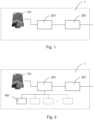
- the signaling device 1 comprises a lighting element 101 mounted on a support, a communication port 301 for receiving an ON/OFF command of the lighting element 101, and a control unit 201 in communication with the communication port 301 and the lighting element 101.
- the lighting element 101 may advantageously comprise a plurality of light sources, for example RGB LEDs arranged on a support having any shape, e.g. circular as in the drawing, which can be controlled by the control unit 201 individually or in blocks to create light patterns of the most varied types in terms of shape, color, intensity, flashing frequency, according to commands which can be set from the outside via the communication port 301.
- a plurality of light sources for example RGB LEDs arranged on a support having any shape, e.g. circular as in the drawing, which can be controlled by the control unit 201 individually or in blocks to create light patterns of the most varied types in terms of shape, color, intensity, flashing frequency, according to commands which can be set from the outside via the communication port 301.
- light signaling may exploited to provide indications on the status of the automation movement system.
- light codes may be set, which signal: opening automation, closing automation, operating anomaly, malfunction, automation awaiting maintenance, time prior to scheduled maintenance and other similar operating statuses.
- An example may be a streetlight configuration in which different colors are used according to the status of the automation of the access point with which the device is associated (opening, closing, forbidden passageway, free passageway).
- the color red may, for example identify a circumstance of forbidden passageway, green a circumstance of free passageway, while a flashing red color could be employed to identify an opening automation, while a flashing red color could indicate a closing automation.
- any type, color tone and flashing may be employed to signal the status of the automation with which the device is associated.
- the commands to the communication port 301 may be sent manually or via remote interfaces.
- such commands are sent by the same central unit which monitors the operation of the automation system, in particular by taking advantage of said communication bus between central unit and system actuation/sensor devices.
- Figure 3 shows an example of a system for controlling the movement of a movable access point, such as a gate, a barrier, a door and the like, in which the signaling device according to the invention may be used.
- the system comprises a bus system 4 to which a movement module 2 for opening/closing the automation, a central control module 3 and a signaling device 1 according to the invention, are connected.
- the modules 2 and 3 may obviously also co-exist in a same device.
- the movement module 2 comprises a motor 102, a motor control device 202, and a port 302 for receiving a barrier movement command via bus 4.
- the central control module 3 comprises a central unit 103, an input 203, and an interface port 303 towards bus 4.
- the central unit 103 is configured to read movement commands of the automation from input 203 and/or from bus 4, and accordingly to send actuation signals to the motor control device 202 via bus 4.
- the light-signaling device 1 is also interfaced with the central unit 103 via the bus communication system 4 so that the central unit 103 may send commands also to the signaling device 1, in particular to the control unit 201 thereof, via the communication port 301.
- the central unit 103 may advantageously be programed to send commands to the signaling device 1 corresponding to system statuses so that the signaling device 1 may accordingly emit a light with a light pattern, color and/or frequency which encodes the system status in the form of light message to send to a user.
- the control unit 201 of the signaling device 1 may be, for example programed to set the lighting element 101 so as to emit a light of a first color, e.g. red, when the central unit controls the closing automation, of a second color, e.g. green, when the central unit controls the opening automation.
- the drive commands may be sent in the form of a single message or of various messages both to the control device 202 of motor 102 of the automation and to the lighting device 1, via said communication system 4.
- control unit 201 of the signaling device 1 may be programed to set the lighting element 101 so as to emit a flashing light during the opening or the closing of the barrier.
- the communication system 4 may advantageously be a bus communication system with a master/slave type protocol, with the central unit 103 being the master, the motor control device 2 and the signaling device 1 being corresponding slaves which receive commands from, and send statuses to, said master.
- There may be further slave devices interfaced with the bus such as, for example photocell safety devices, sensitive edge safety devices, footboard-operated presence detectors, radar presence detectors and other devices typical of this type of systems.
- the same input 203 of the central unit 3 may be supported or replaced by a slave type input device interfaced with the central unit 3 via bus 4, e.g. a key selector switch, a control keypad, a remote control receiver and similar devices.
- the signaling device 1 may comprise one or more interfaces 401 so as to form a hub for connecting with other devices which communicate with the central unit 103 via the control unit 201 and the communication bus 4.
- One of said other devices may be an antenna and the corresponding control electronics so as to associate the signaling device 1 with a wireless gateway functionality, for example AF, Wi-Fi, Bluetooth, Zigbee, GPRS, UMTS, LTE and the like.
- a wireless gateway functionality for example AF, Wi-Fi, Bluetooth, Zigbee, GPRS, UMTS, LTE and the like.
- the antenna is mounted on a base 601 in a cap 501.
- Base 601 may advantageously accommodate electronics 401 for the connection to bus 4, and possibly accessory/expansion boards.
- Bluetooth and Wi-Fi are indeed devices installed on the automation (motor) and therefore, may be shielded by obstacles such as the gate, walls, etc.
- a PIR i.e. an infrared presence detection sensor, both for alarm purposes and for activating a light or a camera with settable intervention times.
- the advantage is obtained of reducing the number of accessories to be connected to the automatism, with apparent reduction in costs and wiring.
- the control unit 201 of the signaling device 1 may also advantageously be programed to set the lighting element 101 so as to emit a light pattern which encodes a type of malfunction or anomaly. This may be particularly advantageous when technical maintenance is provided.
- a portable device such as a smartphone or a tablet, provided with camera for the optical reading of the light pattern emitted by the signaling device and a table for transcoding light codes to allow an operator to interpret the type of malfunction signaled by the signaling device.
- the display of the graphic codes which may be interpreted with the use of augmented reality via the smartphone, is a method for simplifying and making more efficient the work of the installer and the maintenance provided.
Landscapes
- Physics & Mathematics (AREA)
- Electromagnetism (AREA)
- General Physics & Mathematics (AREA)
- Circuit Arrangement For Electric Light Sources In General (AREA)
Claims (15)
- Lichtsignalvorrichtung für automatisierte Zugänge, wie z. B. Tore und/oder automatische Schranken, umfassend:ein Beleuchtungselement (101);einen Kommunikationsanschluss (301) zum Empfang von Befehlen für das Beleuchtungselement;eine Steuereinheit (201), die mit dem Kommunikationsanschluss (301) und dem Beleuchtungselement (101) in Verbindung steht, wobei die Steuereinheit (201) so konfiguriert ist, dass sie die Befehle von dem Kommunikationsanschluss (301) liest und dementsprechend das Beleuchtungselement (101) so steuert, dass Lichtmuster mit unterschiedlicher Form und/oder Farbe und/oder Intensität auf der Grundlage der empfangenen Befehle eingestellt werden,dadurch gekennzeichnet, dasssie ferner eine Antenne (501) umfasst, die auf einem Träger (601) montiert ist, und eine Schnittstellenelektronik (401) zur Antenne (501) hin, wobei die Schnittstellenelektronik mit der Steuereinheit (201) in Verbindung steht, um Daten über den Kommunikationsanschluss (301) auszutauschen, um ein drahtloses Kommunikations-Gateway-Modul zu bilden, beispielsweise gemäß Wi-Fi-, Bluetooth-, Zigbee-, GPRS-, UMTS-, LTE-Protokollen und dergleichen.
- Vorrichtung nach Anspruch 1, wobei das Beleuchtungselement (101) eine Vielzahl von Lichtquellen umfasst, die von der Steuereinheit (201) einzeln oder in Blöcken angesteuert werden können, um Lichtmuster zu erzeugen, die Informationen über den Zustand der Automatisierung, die der Lichtsignalvorrichtung (1) zugeordnet oder zuordenbar ist, oder einfache Beleuchtungs- oder Leitfunktionen kodieren.
- Vorrichtung nach Anspruch 2, wobei die Zustandsinformation ausgewählt ist aus der Gruppe bestehend aus: Öffnungsautomatik, Schließautomatik, Betriebsanomalie, Störung, zu wartende Automatisierung, Zeit vor der geplanten Wartung.
- Vorrichtung nach einem oder mehreren der vorstehenden Ansprüche, wobei die Steuereinheit (201) so programmiert ist, dass sie das Beleuchtungselement (101) so einstellt, dass es ein Blinklicht mit einer Frequenz aussendet, die eine Art von Störung oder Anomalie kodiert.
- Vorrichtung nach einem oder mehreren der vorstehenden Ansprüche, wobei das Beleuchtungselement eine Matrix aus RGB-LEDs umfasst, die auf einem Träger mit beliebiger Form angeordnet sind.
- System zur Steuerung der Bewegung einer beweglichen Automatik für Zugangspunkte wie ein Tor, eine Schranke, eine Tür und dergleichen, wobei das System umfasst:einen Motor (102) zum Öffnen und Schließen der Automatisierung;eine Steuervorrichtung (202) für den Motor (102);einen Anschluss (302) zum Empfang von Bewegungsbefehlen für die Automatisierung;ein Kommunikationssystem (4);eine zentrale Steuereinheit (103), die über eine Schnittstelle (303) mit dem Kommunikationssystem (4) mit einem Eingang (203) der Steuervorrichtung (202) in Verbindung steht, wobei die zentrale Steuereinheit (103) so konfiguriert ist, dass sie die Bewegungsbefehle für die Automatisierung von dem Eingang (203) liest und dementsprechend Betätigungssignale an die Motorsteuervorrichtung (202) sendet,dadurch gekennzeichnet, dass es eine Lichtsignalvorrichtung (1) nach einem der Ansprüche 1 bis 5 umfasst,wobei die Lichtsignalvorrichtung (1) über das Kommunikationssystem (4) mit der zentralen Steuereinheit (103) verbunden ist, so dass die zentrale Steuereinheit (103) die Befehle für das Beleuchtungselement an die Lichtsignalvorrichtung (1) senden kann.
- System nach Anspruch 6, wobei die zentrale Steuereinheit (103) so programmiert ist, dass sie die Befehle an die Lichtsignalvorrichtung (1) entsprechend den Systemzuständen sendet, so dass die Lichtsignalvorrichtung (1) dementsprechend ein Licht mit einem Intensitäts-, Farb- und/oder Frequenzmuster aussenden kann, das den Systemzustand in Form einer Lichtnachricht kodiert, die an einen Benutzer zu senden ist.
- System nach Anspruch 6 oder 7, wobei die Steuereinheit (201) der Lichtsignalvorrichtung (1) so programmiert ist, dass sie das Beleuchtungselement (101) so einstellt, dass es ein Licht einer ersten Farbe, z. B. rot, aussendet, wenn die Zentraleinheit (103) das Schließen der Automatisierung steuert, und einer zweiten Farbe, z. B. grün, wenn die Zentraleinheit (103) das Öffnen der Automatisierung steuert, wobei die Befehle in Form einer einzigen Nachricht oder verschiedener Nachrichten sowohl an die Motorsteuervorrichtung (202) der Automatisierung als auch an die Steuereinheit (201) der Beleuchtungsvorrichtung (1) über das Kommunikationssystem (4) gesendet werden.
- System nach einem oder mehreren der vorstehenden Ansprüche 6 bis 8, wobei die Steuereinheit (201) der Lichtsignalvorrichtung (1) so programmiert ist, dass sie das Beleuchtungselement (101) so einstellt, dass es während des Öffnens oder Schließens der Automatisierung ein Blinklicht aussendet.
- System nach einem oder mehreren der vorstehenden Ansprüche 6 bis 9, wobei das Kommunikationssystem (4) ein Buskommunikationssystem mit einem Master/Slave-Protokoll ist, wobei die zentrale Steuereinheit (103) der Master ist und die Motorsteuervorrichtung (202) und die Lichtsignalvorrichtung (1) entsprechende Slaves sind, die Befehle von dem Master empfangen und Zustände an diesen senden.
- System nach Anspruch 10, wobei die Lichtsignalvorrichtung (1) eine oder mehrere Schnittstellen (401) umfasst, um einen Knotenpunkt zur Verbindung mit anderen Vorrichtungen zu bilden, die über die Steuereinheit (201) und den Kommunikationsbus (4) mit der zentralen Steuereinheit (103) kommunizieren.
- System nach Anspruch 11, wobei eine der anderen Vorrichtungen die Antenne (501) und die entsprechende Schnittstellenelektronik ist, die es ermöglicht, die Lichtsignalvorrichtung (1) einer drahtlosen Gateway-Funktionalität zuzuordnen.
- System nach einem oder mehreren der vorstehenden Ansprüche 6 bis 12, wobei die Steuereinheit (201) der Lichtsignalvorrichtung (1) so programmiert ist, dass sie das Beleuchtungselement so einstellt, dass es ein Lichtmuster aussendet, das eine Art von Störung oder eine Anomalie kodiert.
- System nach Anspruch 13, ferner umfassend eine tragbare Vorrichtung zum optischen Lesen des von der Lichtsignalvorrichtung ausgesendeten Lichtmusters, wobei die tragbare Vorrichtung eine Tabelle zur Transkodierung des Lichtmusters aufweist, um einem Bediener die Interpretation der Art von Störung zu ermöglichen, die von der Lichtsignalvorrichtung signalisiert wird.
- System nach Anspruch 14, wobei es sich bei der tragbaren Vorrichtung um ein Smartphone oder ein Tablet handelt, das mit einer Kamera ausgestattet ist, mit der der von der Lichtsignalvorrichtung ausgesendete Lichtcode gelesen werden kann.
Priority Applications (2)
| Application Number | Priority Date | Filing Date | Title |
|---|---|---|---|
| EP21150472.5A EP4027313B1 (de) | 2021-01-07 | 2021-01-07 | Lichtsignalisierungsvorrichtung für zugangspunkte |
| PL21150472.5T PL4027313T3 (pl) | 2021-01-07 | 2021-01-07 | Urządzenie sygnalizujące światłem dla punktów dostępu |
Applications Claiming Priority (1)
| Application Number | Priority Date | Filing Date | Title |
|---|---|---|---|
| EP21150472.5A EP4027313B1 (de) | 2021-01-07 | 2021-01-07 | Lichtsignalisierungsvorrichtung für zugangspunkte |
Publications (2)
| Publication Number | Publication Date |
|---|---|
| EP4027313A1 EP4027313A1 (de) | 2022-07-13 |
| EP4027313B1 true EP4027313B1 (de) | 2024-05-29 |
Family
ID=74853505
Family Applications (1)
| Application Number | Title | Priority Date | Filing Date |
|---|---|---|---|
| EP21150472.5A Revoked EP4027313B1 (de) | 2021-01-07 | 2021-01-07 | Lichtsignalisierungsvorrichtung für zugangspunkte |
Country Status (2)
| Country | Link |
|---|---|
| EP (1) | EP4027313B1 (de) |
| PL (1) | PL4027313T3 (de) |
Citations (10)
| Publication number | Priority date | Publication date | Assignee | Title |
|---|---|---|---|---|
| WO2003104907A1 (en) | 2002-06-06 | 2003-12-18 | Mhouse Srl | Electrical system for controlling at least one gate or door or similar element of the type moved electrically |
| WO2005080728A2 (en) | 2004-02-19 | 2005-09-01 | Wayne-Dalton Corp. | Operating system for a motorized barrier operator with a radio frequency energized light kit and/or switch and methods for programming the same |
| WO2006133981A1 (en) | 2005-04-22 | 2006-12-21 | Nice Spa | Light-emitting device |
| WO2010095161A1 (en) | 2009-02-23 | 2010-08-26 | Rib S.R.L. | Signaling device in particular for automatic opening/closing systems |
| DE202011103660U1 (de) | 2010-09-16 | 2011-12-05 | Siemens Ag Österreich | Signalisierungseinrichtung |
| WO2016022534A2 (en) | 2014-08-06 | 2016-02-11 | Rite-Hite Holding Corporation | Methods and systems to indicate the status of door operations |
| US20160063823A1 (en) | 2014-09-02 | 2016-03-03 | Schneider Electric Industries Sas | Multicolor signal light and controlling method thereof |
| US9997070B1 (en) | 2017-05-18 | 2018-06-12 | Abl Ip Holding Llc | Use of software configurable luminaire in parking application |
| US10087673B1 (en) | 2015-03-13 | 2018-10-02 | Gto Access Systems, Llc | Apparatus and techniques for door opener systems |
| WO2018185019A1 (de) | 2017-04-07 | 2018-10-11 | Hörmann KG Antriebstechnik | Abschlussantriebsvorrichtung, damit versehener abschluss und betriebsverfahren |
-
2021
- 2021-01-07 EP EP21150472.5A patent/EP4027313B1/de not_active Revoked
- 2021-01-07 PL PL21150472.5T patent/PL4027313T3/pl unknown
Patent Citations (10)
| Publication number | Priority date | Publication date | Assignee | Title |
|---|---|---|---|---|
| WO2003104907A1 (en) | 2002-06-06 | 2003-12-18 | Mhouse Srl | Electrical system for controlling at least one gate or door or similar element of the type moved electrically |
| WO2005080728A2 (en) | 2004-02-19 | 2005-09-01 | Wayne-Dalton Corp. | Operating system for a motorized barrier operator with a radio frequency energized light kit and/or switch and methods for programming the same |
| WO2006133981A1 (en) | 2005-04-22 | 2006-12-21 | Nice Spa | Light-emitting device |
| WO2010095161A1 (en) | 2009-02-23 | 2010-08-26 | Rib S.R.L. | Signaling device in particular for automatic opening/closing systems |
| DE202011103660U1 (de) | 2010-09-16 | 2011-12-05 | Siemens Ag Österreich | Signalisierungseinrichtung |
| WO2016022534A2 (en) | 2014-08-06 | 2016-02-11 | Rite-Hite Holding Corporation | Methods and systems to indicate the status of door operations |
| US20160063823A1 (en) | 2014-09-02 | 2016-03-03 | Schneider Electric Industries Sas | Multicolor signal light and controlling method thereof |
| US10087673B1 (en) | 2015-03-13 | 2018-10-02 | Gto Access Systems, Llc | Apparatus and techniques for door opener systems |
| WO2018185019A1 (de) | 2017-04-07 | 2018-10-11 | Hörmann KG Antriebstechnik | Abschlussantriebsvorrichtung, damit versehener abschluss und betriebsverfahren |
| US9997070B1 (en) | 2017-05-18 | 2018-06-12 | Abl Ip Holding Llc | Use of software configurable luminaire in parking application |
Also Published As
| Publication number | Publication date |
|---|---|
| PL4027313T3 (pl) | 2024-09-02 |
| EP4027313A1 (de) | 2022-07-13 |
Similar Documents
| Publication | Publication Date | Title |
|---|---|---|
| KR200394747Y1 (ko) | 다수의 조명을 제어하는 시스템 | |
| US10443296B2 (en) | Apparatus and techniques for door opener systems | |
| CA3071985A1 (en) | Methods and systems for decentralized train control | |
| US20050104745A1 (en) | Emergency vehicle traffic signal preemption system | |
| AU2010311317B2 (en) | Arrangement for passage control of mining vehicles | |
| US20080218380A1 (en) | Distributed Intelligence For Traffic Signal Control | |
| CN101739780A (zh) | 具有至少两个警示灯的警示光装置 | |
| US11040841B2 (en) | Bollard with integrated control system | |
| EP3305034B1 (de) | Verbesserungen an oder im zusammenhang mit leuchten | |
| US5973616A (en) | Pager supported traffic signal controller | |
| US20150326314A1 (en) | Tandem, Visible Light and RF Communication System | |
| EP4027313A1 (de) | Lichtsignalisierungsvorrichtung für zugangspunkte | |
| US10081318B2 (en) | Method and apparatus for operating a motor vehicle | |
| CN108121283B (zh) | 一种内河船闸启闭控制的智能辅助装置及使用方法 | |
| WO2010013043A1 (en) | Method and device for vehicle identification and immobilisation | |
| CN214273738U (zh) | 一种基于姿态传感器的隧道车辆撞击预警装置 | |
| JP5454551B2 (ja) | 交通信号情報提供システム及び情報提供装置 | |
| AU2015200518B2 (en) | Controller for operating a closure | |
| KR20060134238A (ko) | 다수의 조명을 제어하는 시스템 | |
| CN215182175U (zh) | 闸机控制器及控制系统 | |
| AU2018315235B2 (en) | Temporary traffic signalling system | |
| CN112767716B (zh) | 一种与信号灯无线交互的智能道路信号机 | |
| KR19990075553A (ko) | 무선 교통 관제 신호 제어 방법 및 장치 | |
| JP2948811B1 (ja) | 自動開閉装置用リモコン送信機 | |
| KR101457033B1 (ko) | 양방향 원격 제어방법 및 이를 이용한 양방향 원격 제어장치 |
Legal Events
| Date | Code | Title | Description |
|---|---|---|---|
| PUAI | Public reference made under article 153(3) epc to a published international application that has entered the european phase |
Free format text: ORIGINAL CODE: 0009012 |
|
| STAA | Information on the status of an ep patent application or granted ep patent |
Free format text: STATUS: THE APPLICATION HAS BEEN PUBLISHED |
|
| AK | Designated contracting states |
Kind code of ref document: A1 Designated state(s): AL AT BE BG CH CY CZ DE DK EE ES FI FR GB GR HR HU IE IS IT LI LT LU LV MC MK MT NL NO PL PT RO RS SE SI SK SM TR |
|
| STAA | Information on the status of an ep patent application or granted ep patent |
Free format text: STATUS: REQUEST FOR EXAMINATION WAS MADE |
|
| 17P | Request for examination filed |
Effective date: 20230111 |
|
| RBV | Designated contracting states (corrected) |
Designated state(s): AL AT BE BG CH CY CZ DE DK EE ES FI FR GB GR HR HU IE IS IT LI LT LU LV MC MK MT NL NO PL PT RO RS SE SI SK SM TR |
|
| P01 | Opt-out of the competence of the unified patent court (upc) registered |
Effective date: 20230525 |
|
| GRAP | Despatch of communication of intention to grant a patent |
Free format text: ORIGINAL CODE: EPIDOSNIGR1 |
|
| STAA | Information on the status of an ep patent application or granted ep patent |
Free format text: STATUS: GRANT OF PATENT IS INTENDED |
|
| RIC1 | Information provided on ipc code assigned before grant |
Ipc: G08B 5/38 20060101ALI20231205BHEP Ipc: G08B 5/36 20060101AFI20231205BHEP |
|
| INTG | Intention to grant announced |
Effective date: 20231222 |
|
| GRAS | Grant fee paid |
Free format text: ORIGINAL CODE: EPIDOSNIGR3 |
|
| GRAA | (expected) grant |
Free format text: ORIGINAL CODE: 0009210 |
|
| STAA | Information on the status of an ep patent application or granted ep patent |
Free format text: STATUS: THE PATENT HAS BEEN GRANTED |
|
| AK | Designated contracting states |
Kind code of ref document: B1 Designated state(s): AL AT BE BG CH CY CZ DE DK EE ES FI FR GB GR HR HU IE IS IT LI LT LU LV MC MK MT NL NO PL PT RO RS SE SI SK SM TR |
|
| REG | Reference to a national code |
Ref country code: CH Ref legal event code: EP |
|
| REG | Reference to a national code |
Ref country code: IE Ref legal event code: FG4D |
|
| REG | Reference to a national code |
Ref country code: DE Ref legal event code: R096 Ref document number: 602021013677 Country of ref document: DE |
|
| REG | Reference to a national code |
Ref country code: LT Ref legal event code: MG9D |
|
| REG | Reference to a national code |
Ref country code: NL Ref legal event code: MP Effective date: 20240529 |
|
| PG25 | Lapsed in a contracting state [announced via postgrant information from national office to epo] |
Ref country code: IS Free format text: LAPSE BECAUSE OF FAILURE TO SUBMIT A TRANSLATION OF THE DESCRIPTION OR TO PAY THE FEE WITHIN THE PRESCRIBED TIME-LIMIT Effective date: 20240929 |
|
| PG25 | Lapsed in a contracting state [announced via postgrant information from national office to epo] |
Ref country code: BG Free format text: LAPSE BECAUSE OF FAILURE TO SUBMIT A TRANSLATION OF THE DESCRIPTION OR TO PAY THE FEE WITHIN THE PRESCRIBED TIME-LIMIT Effective date: 20240529 |
|
| PG25 | Lapsed in a contracting state [announced via postgrant information from national office to epo] |
Ref country code: FI Free format text: LAPSE BECAUSE OF FAILURE TO SUBMIT A TRANSLATION OF THE DESCRIPTION OR TO PAY THE FEE WITHIN THE PRESCRIBED TIME-LIMIT Effective date: 20240529 Ref country code: HR Free format text: LAPSE BECAUSE OF FAILURE TO SUBMIT A TRANSLATION OF THE DESCRIPTION OR TO PAY THE FEE WITHIN THE PRESCRIBED TIME-LIMIT Effective date: 20240529 |
|
| PG25 | Lapsed in a contracting state [announced via postgrant information from national office to epo] |
Ref country code: GR Free format text: LAPSE BECAUSE OF FAILURE TO SUBMIT A TRANSLATION OF THE DESCRIPTION OR TO PAY THE FEE WITHIN THE PRESCRIBED TIME-LIMIT Effective date: 20240830 |
|
| REG | Reference to a national code |
Ref country code: AT Ref legal event code: MK05 Ref document number: 1691307 Country of ref document: AT Kind code of ref document: T Effective date: 20240529 |
|
| PG25 | Lapsed in a contracting state [announced via postgrant information from national office to epo] |
Ref country code: ES Free format text: LAPSE BECAUSE OF FAILURE TO SUBMIT A TRANSLATION OF THE DESCRIPTION OR TO PAY THE FEE WITHIN THE PRESCRIBED TIME-LIMIT Effective date: 20240529 |
|
| PG25 | Lapsed in a contracting state [announced via postgrant information from national office to epo] |
Ref country code: AT Free format text: LAPSE BECAUSE OF FAILURE TO SUBMIT A TRANSLATION OF THE DESCRIPTION OR TO PAY THE FEE WITHIN THE PRESCRIBED TIME-LIMIT Effective date: 20240529 |
|
| PG25 | Lapsed in a contracting state [announced via postgrant information from national office to epo] |
Ref country code: LV Free format text: LAPSE BECAUSE OF FAILURE TO SUBMIT A TRANSLATION OF THE DESCRIPTION OR TO PAY THE FEE WITHIN THE PRESCRIBED TIME-LIMIT Effective date: 20240529 |
|
| PG25 | Lapsed in a contracting state [announced via postgrant information from national office to epo] |
Ref country code: NO Free format text: LAPSE BECAUSE OF FAILURE TO SUBMIT A TRANSLATION OF THE DESCRIPTION OR TO PAY THE FEE WITHIN THE PRESCRIBED TIME-LIMIT Effective date: 20240829 Ref country code: LV Free format text: LAPSE BECAUSE OF FAILURE TO SUBMIT A TRANSLATION OF THE DESCRIPTION OR TO PAY THE FEE WITHIN THE PRESCRIBED TIME-LIMIT Effective date: 20240529 Ref country code: IS Free format text: LAPSE BECAUSE OF FAILURE TO SUBMIT A TRANSLATION OF THE DESCRIPTION OR TO PAY THE FEE WITHIN THE PRESCRIBED TIME-LIMIT Effective date: 20240929 Ref country code: HR Free format text: LAPSE BECAUSE OF FAILURE TO SUBMIT A TRANSLATION OF THE DESCRIPTION OR TO PAY THE FEE WITHIN THE PRESCRIBED TIME-LIMIT Effective date: 20240529 Ref country code: GR Free format text: LAPSE BECAUSE OF FAILURE TO SUBMIT A TRANSLATION OF THE DESCRIPTION OR TO PAY THE FEE WITHIN THE PRESCRIBED TIME-LIMIT Effective date: 20240830 Ref country code: FI Free format text: LAPSE BECAUSE OF FAILURE TO SUBMIT A TRANSLATION OF THE DESCRIPTION OR TO PAY THE FEE WITHIN THE PRESCRIBED TIME-LIMIT Effective date: 20240529 Ref country code: ES Free format text: LAPSE BECAUSE OF FAILURE TO SUBMIT A TRANSLATION OF THE DESCRIPTION OR TO PAY THE FEE WITHIN THE PRESCRIBED TIME-LIMIT Effective date: 20240529 Ref country code: BG Free format text: LAPSE BECAUSE OF FAILURE TO SUBMIT A TRANSLATION OF THE DESCRIPTION OR TO PAY THE FEE WITHIN THE PRESCRIBED TIME-LIMIT Effective date: 20240529 Ref country code: AT Free format text: LAPSE BECAUSE OF FAILURE TO SUBMIT A TRANSLATION OF THE DESCRIPTION OR TO PAY THE FEE WITHIN THE PRESCRIBED TIME-LIMIT Effective date: 20240529 Ref country code: RS Free format text: LAPSE BECAUSE OF FAILURE TO SUBMIT A TRANSLATION OF THE DESCRIPTION OR TO PAY THE FEE WITHIN THE PRESCRIBED TIME-LIMIT Effective date: 20240829 |
|
| PG25 | Lapsed in a contracting state [announced via postgrant information from national office to epo] |
Ref country code: NL Free format text: LAPSE BECAUSE OF FAILURE TO SUBMIT A TRANSLATION OF THE DESCRIPTION OR TO PAY THE FEE WITHIN THE PRESCRIBED TIME-LIMIT Effective date: 20240529 |
|
| PG25 | Lapsed in a contracting state [announced via postgrant information from national office to epo] |
Ref country code: NL Free format text: LAPSE BECAUSE OF FAILURE TO SUBMIT A TRANSLATION OF THE DESCRIPTION OR TO PAY THE FEE WITHIN THE PRESCRIBED TIME-LIMIT Effective date: 20240529 |
|
| PG25 | Lapsed in a contracting state [announced via postgrant information from national office to epo] |
Ref country code: DK Free format text: LAPSE BECAUSE OF FAILURE TO SUBMIT A TRANSLATION OF THE DESCRIPTION OR TO PAY THE FEE WITHIN THE PRESCRIBED TIME-LIMIT Effective date: 20240529 |
|
| PG25 | Lapsed in a contracting state [announced via postgrant information from national office to epo] |
Ref country code: EE Free format text: LAPSE BECAUSE OF FAILURE TO SUBMIT A TRANSLATION OF THE DESCRIPTION OR TO PAY THE FEE WITHIN THE PRESCRIBED TIME-LIMIT Effective date: 20240529 |
|
| PG25 | Lapsed in a contracting state [announced via postgrant information from national office to epo] |
Ref country code: CZ Free format text: LAPSE BECAUSE OF FAILURE TO SUBMIT A TRANSLATION OF THE DESCRIPTION OR TO PAY THE FEE WITHIN THE PRESCRIBED TIME-LIMIT Effective date: 20240529 |
|
| PG25 | Lapsed in a contracting state [announced via postgrant information from national office to epo] |
Ref country code: SK Free format text: LAPSE BECAUSE OF FAILURE TO SUBMIT A TRANSLATION OF THE DESCRIPTION OR TO PAY THE FEE WITHIN THE PRESCRIBED TIME-LIMIT Effective date: 20240529 Ref country code: RO Free format text: LAPSE BECAUSE OF FAILURE TO SUBMIT A TRANSLATION OF THE DESCRIPTION OR TO PAY THE FEE WITHIN THE PRESCRIBED TIME-LIMIT Effective date: 20240529 |
|
| PG25 | Lapsed in a contracting state [announced via postgrant information from national office to epo] |
Ref country code: SM Free format text: LAPSE BECAUSE OF FAILURE TO SUBMIT A TRANSLATION OF THE DESCRIPTION OR TO PAY THE FEE WITHIN THE PRESCRIBED TIME-LIMIT Effective date: 20240529 |
|
| PG25 | Lapsed in a contracting state [announced via postgrant information from national office to epo] |
Ref country code: SM Free format text: LAPSE BECAUSE OF FAILURE TO SUBMIT A TRANSLATION OF THE DESCRIPTION OR TO PAY THE FEE WITHIN THE PRESCRIBED TIME-LIMIT Effective date: 20240529 Ref country code: SK Free format text: LAPSE BECAUSE OF FAILURE TO SUBMIT A TRANSLATION OF THE DESCRIPTION OR TO PAY THE FEE WITHIN THE PRESCRIBED TIME-LIMIT Effective date: 20240529 Ref country code: RO Free format text: LAPSE BECAUSE OF FAILURE TO SUBMIT A TRANSLATION OF THE DESCRIPTION OR TO PAY THE FEE WITHIN THE PRESCRIBED TIME-LIMIT Effective date: 20240529 Ref country code: EE Free format text: LAPSE BECAUSE OF FAILURE TO SUBMIT A TRANSLATION OF THE DESCRIPTION OR TO PAY THE FEE WITHIN THE PRESCRIBED TIME-LIMIT Effective date: 20240529 Ref country code: DK Free format text: LAPSE BECAUSE OF FAILURE TO SUBMIT A TRANSLATION OF THE DESCRIPTION OR TO PAY THE FEE WITHIN THE PRESCRIBED TIME-LIMIT Effective date: 20240529 Ref country code: CZ Free format text: LAPSE BECAUSE OF FAILURE TO SUBMIT A TRANSLATION OF THE DESCRIPTION OR TO PAY THE FEE WITHIN THE PRESCRIBED TIME-LIMIT Effective date: 20240529 |
|
| REG | Reference to a national code |
Ref country code: DE Ref legal event code: R026 Ref document number: 602021013677 Country of ref document: DE |
|
| PLBI | Opposition filed |
Free format text: ORIGINAL CODE: 0009260 |
|
| PLAX | Notice of opposition and request to file observation + time limit sent |
Free format text: ORIGINAL CODE: EPIDOSNOBS2 |
|
| 26 | Opposition filed |
Opponent name: SOMFY ACTIVITES SA Effective date: 20250228 |
|
| PGFP | Annual fee paid to national office [announced via postgrant information from national office to epo] |
Ref country code: DE Payment date: 20241120 Year of fee payment: 5 |
|
| PG25 | Lapsed in a contracting state [announced via postgrant information from national office to epo] |
Ref country code: SI Free format text: LAPSE BECAUSE OF FAILURE TO SUBMIT A TRANSLATION OF THE DESCRIPTION OR TO PAY THE FEE WITHIN THE PRESCRIBED TIME-LIMIT Effective date: 20240529 |
|
| PLBB | Reply of patent proprietor to notice(s) of opposition received |
Free format text: ORIGINAL CODE: EPIDOSNOBS3 |
|
| REG | Reference to a national code |
Ref country code: CH Ref legal event code: PL |
|
| PG25 | Lapsed in a contracting state [announced via postgrant information from national office to epo] |
Ref country code: SE Free format text: LAPSE BECAUSE OF FAILURE TO SUBMIT A TRANSLATION OF THE DESCRIPTION OR TO PAY THE FEE WITHIN THE PRESCRIBED TIME-LIMIT Effective date: 20240529 |
|
| PG25 | Lapsed in a contracting state [announced via postgrant information from national office to epo] |
Ref country code: LU Free format text: LAPSE BECAUSE OF NON-PAYMENT OF DUE FEES Effective date: 20250107 Ref country code: MC Free format text: LAPSE BECAUSE OF FAILURE TO SUBMIT A TRANSLATION OF THE DESCRIPTION OR TO PAY THE FEE WITHIN THE PRESCRIBED TIME-LIMIT Effective date: 20240529 |
|
| PG25 | Lapsed in a contracting state [announced via postgrant information from national office to epo] |
Ref country code: CH Free format text: LAPSE BECAUSE OF NON-PAYMENT OF DUE FEES Effective date: 20250131 |
|
| RDAF | Communication despatched that patent is revoked |
Free format text: ORIGINAL CODE: EPIDOSNREV1 |
|
| REG | Reference to a national code |
Ref country code: DE Ref legal event code: R064 Ref document number: 602021013677 Country of ref document: DE Ref country code: DE Ref legal event code: R103 Ref document number: 602021013677 Country of ref document: DE |
|
| PGFP | Annual fee paid to national office [announced via postgrant information from national office to epo] |
Ref country code: GB Payment date: 20251113 Year of fee payment: 6 |
|
| PGFP | Annual fee paid to national office [announced via postgrant information from national office to epo] |
Ref country code: FR Payment date: 20251117 Year of fee payment: 6 |
|
| PGFP | Annual fee paid to national office [announced via postgrant information from national office to epo] |
Ref country code: BE Payment date: 20251223 Year of fee payment: 6 |
|
| PGFP | Annual fee paid to national office [announced via postgrant information from national office to epo] |
Ref country code: IE Payment date: 20251111 Year of fee payment: 6 |
|
| PGFP | Annual fee paid to national office [announced via postgrant information from national office to epo] |
Ref country code: PL Payment date: 20251104 Year of fee payment: 6 |
|
| RDAG | Patent revoked |
Free format text: ORIGINAL CODE: 0009271 |
|
| STAA | Information on the status of an ep patent application or granted ep patent |
Free format text: STATUS: PATENT REVOKED |
|
| REG | Reference to a national code |
Ref country code: CH Ref legal event code: N12 Free format text: ST27 STATUS EVENT CODE: U-0-0-N10-N12 (AS PROVIDED BY THE NATIONAL OFFICE) Effective date: 20260402 |
|
| PGFP | Annual fee paid to national office [announced via postgrant information from national office to epo] |
Ref country code: IT Payment date: 20251219 Year of fee payment: 6 |
|
| 27W | Patent revoked |
Effective date: 20251222 |
|
| GBPR | Gb: patent revoked under art. 102 of the ep convention designating the uk as contracting state |
Effective date: 20251222 |