EP4027244B1 - Verfahren zum überwachen der ausführung einer grafischen berechnungs- und anzeigekette, die einem anzeigebildschirm eines flugzeugcockpits zugeordnet ist - Google Patents
Verfahren zum überwachen der ausführung einer grafischen berechnungs- und anzeigekette, die einem anzeigebildschirm eines flugzeugcockpits zugeordnet ist Download PDFInfo
- Publication number
- EP4027244B1 EP4027244B1 EP22150428.5A EP22150428A EP4027244B1 EP 4027244 B1 EP4027244 B1 EP 4027244B1 EP 22150428 A EP22150428 A EP 22150428A EP 4027244 B1 EP4027244 B1 EP 4027244B1
- Authority
- EP
- European Patent Office
- Prior art keywords
- parameter
- display
- calculation
- chain
- graphical
- Prior art date
- Legal status (The legal status is an assumption and is not a legal conclusion. Google has not performed a legal analysis and makes no representation as to the accuracy of the status listed.)
- Active
Links
Images



Classifications
-
- G—PHYSICS
- G09—EDUCATION; CRYPTOGRAPHY; DISPLAY; ADVERTISING; SEALS
- G09G—ARRANGEMENTS OR CIRCUITS FOR CONTROL OF INDICATING DEVICES USING STATIC MEANS TO PRESENT VARIABLE INFORMATION
- G09G3/00—Control arrangements or circuits, of interest only in connection with visual indicators other than cathode-ray tubes
- G09G3/006—Electronic inspection or testing of displays and display drivers, e.g. of LED or LCD displays
-
- G—PHYSICS
- G06—COMPUTING OR CALCULATING; COUNTING
- G06F—ELECTRIC DIGITAL DATA PROCESSING
- G06F11/00—Error detection; Error correction; Monitoring
- G06F11/07—Responding to the occurrence of a fault, e.g. fault tolerance
- G06F11/16—Error detection or correction of the data by redundancy in hardware
- G06F11/1629—Error detection by comparing the output of redundant processing systems
- G06F11/165—Error detection by comparing the output of redundant processing systems with continued operation after detection of the error
-
- B—PERFORMING OPERATIONS; TRANSPORTING
- B64—AIRCRAFT; AVIATION; COSMONAUTICS
- B64D—EQUIPMENT FOR FITTING IN OR TO AIRCRAFT; FLIGHT SUITS; PARACHUTES; ARRANGEMENT OR MOUNTING OF POWER PLANTS OR PROPULSION TRANSMISSIONS IN AIRCRAFT
- B64D43/00—Arrangements or adaptations of instruments
-
- G—PHYSICS
- G06—COMPUTING OR CALCULATING; COUNTING
- G06F—ELECTRIC DIGITAL DATA PROCESSING
- G06F11/00—Error detection; Error correction; Monitoring
- G06F11/07—Responding to the occurrence of a fault, e.g. fault tolerance
- G06F11/16—Error detection or correction of the data by redundancy in hardware
- G06F11/1608—Error detection by comparing the output signals of redundant hardware
- G06F11/1616—Error detection by comparing the output signals of redundant hardware where the redundant component is an I/O device or an adapter therefor
- G06F11/162—Displays
-
- G—PHYSICS
- G06—COMPUTING OR CALCULATING; COUNTING
- G06F—ELECTRIC DIGITAL DATA PROCESSING
- G06F11/00—Error detection; Error correction; Monitoring
- G06F11/07—Responding to the occurrence of a fault, e.g. fault tolerance
- G06F11/16—Error detection or correction of the data by redundancy in hardware
- G06F11/18—Error detection or correction of the data by redundancy in hardware using passive fault-masking of the redundant circuits
- G06F11/187—Voting techniques
- G06F11/188—Voting techniques where exact match is not required
-
- G—PHYSICS
- G06—COMPUTING OR CALCULATING; COUNTING
- G06T—IMAGE DATA PROCESSING OR GENERATION, IN GENERAL
- G06T1/00—General purpose image data processing
- G06T1/20—Processor architectures; Processor configuration, e.g. pipelining
-
- G—PHYSICS
- G06—COMPUTING OR CALCULATING; COUNTING
- G06F—ELECTRIC DIGITAL DATA PROCESSING
- G06F2201/00—Indexing scheme relating to error detection, to error correction, and to monitoring
- G06F2201/83—Indexing scheme relating to error detection, to error correction, and to monitoring the solution involving signatures
-
- G—PHYSICS
- G06—COMPUTING OR CALCULATING; COUNTING
- G06F—ELECTRIC DIGITAL DATA PROCESSING
- G06F3/00—Input arrangements for transferring data to be processed into a form capable of being handled by the computer; Output arrangements for transferring data from processing unit to output unit, e.g. interface arrangements
- G06F3/14—Digital output to display device ; Cooperation and interconnection of the display device with other functional units
-
- G—PHYSICS
- G09—EDUCATION; CRYPTOGRAPHY; DISPLAY; ADVERTISING; SEALS
- G09G—ARRANGEMENTS OR CIRCUITS FOR CONTROL OF INDICATING DEVICES USING STATIC MEANS TO PRESENT VARIABLE INFORMATION
- G09G2330/00—Aspects of power supply; Aspects of display protection and defect management
- G09G2330/02—Details of power systems and of start or stop of display operation
- G09G2330/021—Power management, e.g. power saving
-
- G—PHYSICS
- G09—EDUCATION; CRYPTOGRAPHY; DISPLAY; ADVERTISING; SEALS
- G09G—ARRANGEMENTS OR CIRCUITS FOR CONTROL OF INDICATING DEVICES USING STATIC MEANS TO PRESENT VARIABLE INFORMATION
- G09G2330/00—Aspects of power supply; Aspects of display protection and defect management
- G09G2330/06—Handling electromagnetic interferences [EMI], covering emitted as well as received electromagnetic radiation
-
- G—PHYSICS
- G09—EDUCATION; CRYPTOGRAPHY; DISPLAY; ADVERTISING; SEALS
- G09G—ARRANGEMENTS OR CIRCUITS FOR CONTROL OF INDICATING DEVICES USING STATIC MEANS TO PRESENT VARIABLE INFORMATION
- G09G2330/00—Aspects of power supply; Aspects of display protection and defect management
- G09G2330/08—Fault-tolerant or redundant circuits, or circuits in which repair of defects is prepared
-
- G—PHYSICS
- G09—EDUCATION; CRYPTOGRAPHY; DISPLAY; ADVERTISING; SEALS
- G09G—ARRANGEMENTS OR CIRCUITS FOR CONTROL OF INDICATING DEVICES USING STATIC MEANS TO PRESENT VARIABLE INFORMATION
- G09G2380/00—Specific applications
- G09G2380/12—Avionics applications
Definitions
- the present invention also relates to a computer program comprising software instructions which, when executed by a computer, implement such a monitoring method.
- the present invention also relates to an electronic device for monitoring the execution of a first graphic calculation and display chain associated with a first aircraft cockpit display screen, the aircraft cockpit comprising a plurality of screens distinct visualization systems, each associated with its own graphic calculation and display chain.
- the present invention also relates to avionics equipment comprising said first graphics calculation chain and such an electronic monitoring device.
- the present invention also relates to an aircraft comprising such an electronic monitoring device or avionics equipment. Subsequently, by aircraft we mean piloted aircraft such as planes, helicopters but also remotely operated aircraft such as drones.
- the present invention generally relates to the field of graphic computers and on-board avionics visualizations in an aircraft cockpit requiring integrity compatible with flight safety.
- a current solution is based on a principle of monitoring the display of a visualization in the cockpit, provided by a graphic and display calculation chain, by another independent calculation chain, called monitoring, involving low-cost exchanges. latency (or delay) through the avionics communications network or dedicated communications network(s). In order to prevent the comparison thresholds from being too high and therefore of no interest for flight safety, extremely low latencies (delays) of the order of a few tens of milliseconds must be guaranteed.
- US9892479 B1 (PRUITT JAMES S [US ]) describes a system for monitoring the execution of a graphics calculation chain associated with a cockpit display screen of an aircraft.
- DE10229342 A1 (BOSCH GMBH ROBERT [DE] ) also concerns the monitoring of the execution of a graphics calculation chain in the automotive field.
- US7724260 B2 (HONEYWELL INT INC [US] ) describes a method for verifying the rendering of an image in an avionics context, the aim of this document being to verify in particular the accuracy of the display of various indicators of the aircraft, such as the horizon line, the air speed and altitude.
- US2019/286115 A1 (WANG XINXIN [US ]) relates to methods and systems for preventing and detecting hazardous erroneous information in safety-critical display devices within an aircraft cockpit.
- the aim of the invention is then to propose a solution to this problem by avoiding requiring intervention from the crew while automatically locating and sanctioning (i.e. without human intervention) any display malfunction.
- the invention also relates to a computer program comprising software instructions which, when executed by a computer, implement such a monitoring method.
- the invention also relates to an aircraft comprising an electronic monitoring device according to the present invention, as mentioned above, or comprising avionics equipment according to the present invention, as mentioned above.
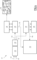
- an avionics assembly 10 of an aircraft cockpit is shown.
- This avionics assembly 10 notably comprises at least two screens. Each screen is associated with a graphic calculation and display chain.
- each graphic calculation and display chain is represented within avionics display equipment 12 and 14.
- Each graphics and display calculation chain conventionally firstly comprises an acquisition module 16 configured to acquire a plurality of input/output parameters of said first graphics calculation chain, these parameters being provided by a plurality of sensors avionics such as sensors C1 and C2 for example capable of respectively providing a parameter P1 for the sensor C1 and a parameter P2 for the sensor C2.
- sensors C1 and C2 for example capable of respectively providing a parameter P1 for the sensor C1 and a parameter P2 for the sensor C2.
- each graphic and display calculation chain comprises, at the output of the acquisition module 16, a processing module 18 configured to determine input/output data from the acquired parameters, and at the output of the processing module 18, a validation module 20 of the input/output data determined by the processing module 18, so that at the output of the validation module 20 the input/output data present a level of criticality conforming to the criticality level DAL A (from English Development Assurance Level ) representative of the fact that a defect in the assembly formed by modules 16, 18 and 20 could cause a problem of misinterpretation of the data by the crew compromising the safety of flight and leading to a hazardous or even catastrophic effect if it was simultaneous on at least two cockpits (ie pilot and co-pilot).
- DAL A from English Development Assurance Level
- each graphic calculation and display chain also conventionally comprises a calculation module 22 configured to determine, for each parameter of said plurality, at least one list of graphic commands capable of generating a symbology associated to represent, then a graphics module 24 configured to generate an image (ie produce the plot of the image) comprising the symbology associated with each parameter, from said at least one list of graphic commands respectively associated with each parameter of said plurality, and finally a display module 26 (ie a screen and lighting system sounds associated, for example an LCD liquid crystal screen (from the English Liquid CrystalDisplay ) configured to display said image comprising the symbology associated with each parameter, on the display screen associated with said graphic calculation and display chain.
- a calculation module 22 configured to determine, for each parameter of said plurality, at least one list of graphic commands capable of generating a symbology associated to represent
- a graphics module 24 configured to generate an image (ie produce the plot of the image) comprising the symbology associated with each parameter, from said at least one list of graphic commands respectively associated with each
- the image displayed by the display module 26 has a criticality level of at least DAL B ( Development Assurance Level ) representative of the fact that a defect in the assembly formed by modules 22, 24 and 26 could cause a problem of erroneous interpretation by one of the pilots leading to a HAZ effect (from English Hazardous ) which could lead to serious damage to the aircraft.
- DAL B Development Assurance Level
- the avionics display equipment 12 and 14 shown are both capable of implementing the graphic generation obtained via the calculation module 22 and the graphics module 24 and the display via the display module 26 (ie a screen ).
- graphics generation and display are united within the same equipment, presenting a system architecture commonly known as SMART.
- the graphic generation and the display are separated and in distinct and independent entities, namely graphic calculators on the one hand (formed modules 16, 18, 20, 22, 24 mentioned above) and separate display module screens 26 on the other hand, the independent graphics computers transmitting the images by video channels to the screens.
- the avionics display equipment 12 is also locally enriched with a unit 28 distinct from the graphics and display calculation chain formed by the aforementioned modules 16, 18, 20, 22, 24, 26.
- Such a unit 28 materially independent of the graphics calculation and display chain formed by the aforementioned modules 16, 18, 20, 22, 24, 26, while being integrated within the avionics display equipment 12, comprises in particular an electronic monitoring device 30 detailed subsequently in relation to the figures 2 And 3 .
- such a device 30 comprises a microprocessor not shown on the figure 1 , a memory not represented on the figure 1 , and interfaces not shown on the figure 1 , to recover the critical parameters 32, data 32 processed progressively by the graphic calculation and display chain formed by the aforementioned modules 16, 18, 20, 22, 24, 26, and in particular data 32 of output of the graphic generation implemented by the graphics module 24 and carry out a monitoring calculation as detailed below in relation to the figure 2 , 3 And 5 .
- such a device 30 is capable of generating at least one sanction 34 in the event of error detection and stopping the primary graphics calculation chain, which does not require any intervention from the pilots and results in the momentary or permanent loss of the primary graphics calculation chain for a single display channel, namely that of the avionics display equipment 12.
- the monitoring device 30 when an error is detected locally by the monitoring device 30, the monitoring device 30 is configured to order, according to arrow 34 of the figure 1 representative of the sanction generated, to the calculation module 22, to restart after having reset its memory (failure which may be linked to a disturbance by an isolated particle PPI (SEU in English for Single event upset ) .
- the loss is in this case advantageously momentary (approximately 2s).
- the monitoring device 30 is then configured to completely shut down the avionics display equipment 12 until at the next power supply off/on not shown, which amounts to a forced shutdown, initiated by the electronic monitoring device 30, until restarted by human intervention.
- the monitoring device 30, when it identifies a failure within the graphics calculation and display chain formed by the aforementioned modules 16, 18, 20, 22, 24, 26 of the avionics display equipment 12, is configured to initiate a display reconfiguration within the aircraft cockpit so that the information initially configured to be displayed by the defective graphics calculation chain of the avionics display equipment 12 is displayed by other avionics equipment display such as avionics equipment 14.
- a display reconfiguration is identical to that conventionally implemented in the event of a screen failure.
- the monitoring device 30 is able to memorize in a local non-volatile memory not shown the event which led to a sanction of the defective module or tool so as to facilitate maintenance corresponding then to a simple removal and replacement of the module, tool or even defective hardware equipment.
- the monitoring device 30 uses simple electronics as detailed below in relation to the figure 2 And 3 executed if necessary by means of a microprocessor not shown of low capacity and, to provide more independence, which can be dissimilar to that of the graphic calculation and display chain formed by the aforementioned modules 16, 18, 20, 22 , 24, 26 of the avionics display equipment 12.
- the inputs/outputs acquired and validated by other avionics equipment are capable of being retransmitted along the arrow 36, via the acquisition module 16 to the electronic monitoring device 30 of the avionics display equipment 12.
- each screen is capable of retransmitting the inputs/outputs acquired and validated within the graphic calculation and display chain associated with it
- DUMB system architecture
- the critical parameters are encapsulated by the other avionics equipment 14 with a CRC cyclic redundancy check.
- the critical input/output data thus encapsulated are transmitted according to arrow 37 for example by the graphic computer (made up of the aforementioned modules 16, 18, 20, 22, 24) of the avionics display equipment 14 towards the electronic device monitoring 30 of the avionics display equipment 12 passing through its acquisition module 16.
- FIG. 2 is a schematic representation of a variant of system architecture according to the present invention. More precisely, the figure 2 illustrates the internal structure of a first graphic calculation and display chain 40 integrated within avionics display equipment 42 according to the present invention.
- Each of the three graphic calculation and display chains comprises an acquisition module 48 configured to acquire a plurality of input/output parameters and in output, a processing module 50 configured to determine input/output data from the acquired parameters.
- the first graphic calculation and display chain 40 further comprises a memory space 52 connected to the processing module 50, and at the output of this processing module 50 conventionally a first calculation tool 54 within the calculation module 22 of there figure 1 not shown on the figure 2 , this first calculation tool 54 being configured to determine, for each parameter of said plurality, at least one list of graphic commands capable of generating a symbology associated with representing, then a graphics module 56 configured to generate an image comprising the symbology associated with each parameter, from said at least one list of graphic commands respectively associated with each parameter of said plurality, and finally a display module comprising a screen whose useful area 58 is configured to display said image comprising the associated symbology.
- the first graphic calculation and display chain 40 further comprises an electronic monitoring device 60.
- the electronic monitoring device 60 comprises a voter 62 which can be activated in particular when at least two other graphic calculation and display chains distinct from the first graphic calculation and display chain 40, transmit by encapsulation of the values of the same parameter also received directly by the first graphic calculation and display chain 40.
- the same input/output parameter P 1 is transmitted, for example by a sensor not shown, directly to the acquisition module 48 of the first graphic calculation and display chain 40 in the form P 1 A, likewise as input to the two other graphics calculation and display chains integrated respectively within the avionics display equipment 44 and 46.
- the processing module 50 of each of the two other graphics calculation and display chains integrated respectively within the avionics display equipment 44 and 46 is configured to encapsulate within a CRC, a value P 1 B for the graphic calculation and display chain integrated within the avionics display equipment 44, and respectively a value P 1 C for the graphic calculation and display chain integrated within the avionics equipment display 46, and transmit the CRC corresponding to the acquisition module 48 of the first graphic calculation and display chain 40, which retransmits these three values P 1 A, P 1 B and P 1 C to the voter 62.
- Such a voter 62 of the electronic monitoring device 60 is then capable of verifying by voting, the current and dynamic value of the parameter P 1 A received directly.
- the voter allows you to know if the direct acquisition of the parameter is P 1 A correct and if the value is equivalent to other independent sources by two-by-two comparison, i.e. P 1 A with P 1 B, P 1 A with P 1 C, P 1 B with P 1 C, and comparison of the difference obtained in each two-by-two comparison at the same tolerance threshold.
- the local acquisition chain 40 of the avionics display equipment 42 receives from a sensor, not shown on the figure 2 , the parameter P 1 A at a first time ta, then externally and encapsulated within a CRC, the same parameter P 1 , coming from the same sensor, in the form P 1 B at time t 1 transmitted by the processing module 50 of the acquisition chain integrated within the avionics display equipment 44, and the same parameter P 1 , coming from the same sensor, in the form P 1 C at time t 2 transmitted by the processing module 50 of the acquisition chain integrated within the avionics display equipment 46.
- the times t 0 , t 1 , t 2 are constrained to low latency (ie lower than a predetermined latency threshold) which makes it possible to reduce the exchange constraint on the network, or, as an alternative, the parameters P 1 A, P 1 B and P 1 C are dated which then allows to identify them.
- the voter 62 detects and locates that there is a source of failure within the acquisition modules 48 and processing modules 50 of the local acquisition chain 40 of the avionics equipment d display 42, and consequently the electronic monitoring device 60 issues a sanction.
- the two-by-two comparison implemented by the voter 62 results in having a valid voting value at its output making it possible to identify the parameter, among the parameters P 1 A, P 1 B and P 1 C, which is not within the tolerance (note here that we do not consider the case of double failure).
- the electronic monitoring device 60 is configured to activate a second calculation tool 64 at within the calculation module 22 of the figure 1 not shown on the figure 2 , this second calculation tool 64 being able to duplicate the list of graphic commands associated with the parameter P 1 determined by the first calculation tool 54 and insert it within this second calculation tool 64 of the calculation module 22.
- a sanction is generated to, as indicated previously, restart and/or stop the graphics and display calculation chain 40 integrated within avionics display equipment 42, which does not require any intervention from the pilots and results in the momentary or permanent loss of the primary graphics calculation chain 40 for a single display channel, namely that of the avionics display equipment 42.
- a voter principle is proposed according to the present invention which has the advantage of identifying the invalid source and always having a valid value of the parameter (always considering that there can only be one simultaneous failure). In this case, availability is improved.
- the electronic monitoring device 60 which ensures that the set of critical parameters received from the independent calculation units (i.e. from each graphic calculation and display chain of the equipment 42, 44 and 46 respectively) are integrity due to the comparison of the encapsulation CRC and the result of the vote with at least three available sources including one local (i.e. here that of the graphics calculation and display chain 40 integrated within avionics equipment of display 42) and two others from external computers (the graphic calculation and display chains integrated within the avionics display equipment 44 and 46).
- the independent calculation units i.e. from each graphic calculation and display chain of the equipment 42, 44 and 46 respectively
- the electronic monitoring device 60 which ensures that the set of critical parameters received from the independent calculation units (i.e. from each graphic calculation and display chain of the equipment 42, 44 and 46 respectively) are integrity due to the comparison of the encapsulation CRC and the result of the vote with at least three available sources including one local (i.e. here that of the graphics calculation and display chain 40 integrated within avionics equipment of display 42) and two others from external
- a notable difference i.e. a difference in values greater than one predetermined threshold
- the input output parameters acquired locally on the one hand and those received from at least one external independent chain makes it possible to raise an error resulting in a clear indication of the risk of error on these parameters (avoid a error not detected) or by inhibition of the parameter considered in the event of a difference between the two distinct sources.
- the electronic monitoring device 60 and where appropriate via the voter 62, which in the presence of a verified value of P 1 A has activated the second calculation tool 64, is optionally capable of modifying the value of P 1 A to generate a known approximate reference value closest to P 1 A belonging to a database of said parameter with a threshold compatible with the flight safety objectives, and to transmit this value to generate a micro-pattern (or a micro-image) associated by execution, by the graphics module 56, of the list of graphics commands associated with the parameter P 1 .
- each parameter has a representative image (ie a symbology) for the attention of the pilot.
- the present invention proposes via the second calculation tool 64 then the graphics module 56 to generate a micro-pattern (in English pattern ) corresponding to a simplified representative reference image of a critical parameter.
- This micro-pattern is according to the present invention reintroduced into the graphics calculation and display chain 40 in order to ensure that it is capable of correctly processing each input/output parameter until its representation in the screen memory (set of pixels).
- the generation by the first calculation tool 54 and by the second calculation tool 64, and respectively the graphic execution by the graphics module 56 of the list of graphic commands specific to each of these tools calculation 54 and 64 is deterministic and leads to the same result even if executed a few milliseconds one after the other.
- the list of graphic commands generated by the calculation tool 64 and executed by the graphics module 56 is capable of producing an associated micro-pattern in a screen area 66 not visible to the driver but forming part of the display resource .
- the operational image suitable for being displayed in the useful area 58 of the screen of the graphics calculation and display chain 40 cannot include an image that is both coherent and ambiguous capable of misleading a pilot (from the English missleading ) corresponding to the display of one or more coherent parameters shifted by a plausible value and not immediately detectable by the pilots ( parameter drift, moderate deviation, etc.) or to an image which would remain frozen for several hundred milliseconds but which would not show any deterioration.
- the present invention proposes to activate the micro-patterns differently from one drawing cycle to the other implementation by the graphics module 56 (ie to activate the micro-patterns at distinct times from one graphics generation cycle to another).
- the micro-patterns are traced by the graphics module 56 in a screen area 66 not visible to the driver but forming part of the display resource and transmitted to a module 68 of the electronic monitoring device 60.
- the module 68 is configured to generate, for each current micro-pattern displayed in the non-visible screen area 66, an associated CRC cyclic redundancy code and transmit it to the comparison module 70 (ie a configured hardware electronic comparator, for the value of the parameter associated with the current micro-pattern, to compare this CRC associated with the current micro-pattern to a CRC of reference micro-pattern (ie expected) and stored beforehand in a dedicated memory space of the electronic monitoring device 60 and/or in an external database accessible by the electronic monitoring device 60, the dedicated memory space and/or the external database being not shown.
- the comparison module 70 ie a configured hardware electronic comparator, for the value of the parameter associated with the current micro-pattern, to compare this CRC associated with the current micro-pattern to a CRC of reference micro-pattern (i
- the comparison result produced by the comparison module 70 is binary, either the current and reference micro-pattern CRCs are identical or they are different, and in the event of a deviation, the electronic monitoring device 60 is then configured to sanction automatically said first graphic calculation and display chain 40 by implementing at least one suspension of its execution for the parameter associated with the current micro-pattern CRC distinct from the reference micro-pattern CRC or even the following total stop the impact of this parameter on flight safety, as illustrated in dotted lines by the sanction arrow going from the comparison module 70 of the electronic monitoring device 60 to the processing module 50.
- Such a comparison module 70 located in the electronic monitoring device 60 is therefore configured to implement an independent comparison with respect to the graphic and display calculation chain 40 conventionally formed only of modules 48, 50, 54, 56 and 58 cited above.
- the parameter of the micro-pattern is according to the present invention reduced to a known value close to and consistent with an acceptable tolerance predetermined for the pilot task associated with the parameter in question.
- the CRC of each reference micro-pattern (ie expected), also called micro-pattern signature, is determined by following the predetermined thresholds of acceptable tolerance as described below in relation to the Figure 3 .
- FIG. 3 is a schematic representation of an example application of the present invention, namely the display of altitude.
- an avionics system 72 of an aircraft cockpit is shown, and notably comprises a plurality 74 of critical parameter sensors, and several distinct graphic calculation and display chains, namely at least the graphic calculation chain and display 76 and the graphic calculation and display chain 78 whose operation is controlled (i.e. monitored) by a monitoring unit 80.
- one of the plurality of sensors 74 provides directly to the acquisition module 82 of the graphics calculation and display chain 78 an altitude of 1043 feet at a time t 0 .
- the acquisition module 82 via a filtering tool transforms this value which passes, for example from 1043 feet to 1040 feet.
- the other graphic calculation and display chain 76 provides at a time t 1 an altitude of 1056 feet, this altitude value being encapsulated by CRC.
- the two values of 1040 feet (provided directly) and 1056 feet (provided indirectly by the graphic calculation and display chain 76) are transmitted by the acquisition module 82, via the arrow 86 to the device.
- monitoring 88 according to the present invention and in particular to a first comparator 90 which compares the difference of 16 feet between these two values with a first predetermined threshold value of said parameter.
- the monitoring device 88 is configured to automatically generate a sanction S of the first graphic calculation and display chain 78 by implementing at least one suspension of its execution.
- the first comparator 90 optionally activates a module 92 for determining an approximate reference value configured to reduce the current and dynamic value of each parameter to said approximate reference value as a function of said threshold of tolerance specific to the altitude and then provides, according to arrow 94, a value of 1050 feet to a calculation module 96 (said approximate reference value being known and stored in the database).
- the acquisition module 82 provides, according to an arrow 100, directly and conventionally the current altitude value of 1040 feet after filtering which it obtained from the value provided directly by the altitude sensor of the plurality 74 of critical parameter sensors.
- the calculation module 96 includes two tools 102 A and 102 B for executing a calculation 104 (ie a calculation code) associated with the altitude parameter and duplicated between these two calculation tools 102 A and 102 B.
- a calculation 104 ie a calculation code
- the two tools 102 A and 102 B are configured to apply substantially the same list of graphic commands associated with the same altitude parameter, with the difference that the tool 102a corresponds to the classic calculation tool of the graphic calculation and display chain 78 and is capable of completely generating the image to be displayed to the driver in a useful display area according to a calculation cycle at 20Hz, while the tool 102 B corresponds to a calculation tool activated by the monitoring device 88 to generate only the altitude micro-pattern according to a calculation cycle at 1Hz for example.
- Tool 102 A therefore receives as input the altitude value 1040 feet while tool 102 B receives as input the altitude value 1050 feet.
- the outputs of the calculation tools 102 A and 102 B are respectively connected to tools 106 A and 106 B for generating a graphics stack.
- the graphic stack generation tool 106 A of the calculation module 96 is capable of transmitting, along the arrow 108, to a second comparator 110 of the monitoring device 88, the value of said parameter determined for display (ie capable of being transmitted for display to the graphics module 112).
- the second comparator 110 is capable of comparing this value before display with that received directly by the acquisition module 82 of the graphic calculation chain 78, and in the event of a deviation greater than a second predetermined threshold value of said altitude parameter , to automatically sanction, by generating a sanction S, the graphic calculation and display chain 78 by implementing at least one suspension of its execution.
- the value of the parameter must be returned to the monitoring device 88 to ensure that the difference between the value transmitted to the micro-pattern (i.e. 1050 feet) and that of the display (i.e. 1040 feet) are consistent and within the acceptable tolerance for this type of parameter.
- An algorithm for extracting the parameter on the basis of the graphics stack is therefore suitable for implementation according to the present invention.
- the monitoring mechanism implemented by the monitoring device 88 manipulates non-similar data and that the result transmitted to the monitoring device 88 cannot consistently compensate the chain primary display formed of elements 82, 102 A , 106 A , 112 and generating the overall image 114, and the graphic calculation chain for generating the micro-pattern formed of elements 82, 102 B , 106 B , 112 and generating the micro-pattern 116 suitable for being displayed in a non-visible area of the screen but belonging to the display resource.
- the graphics module 112 is also according to the present invention configured to transmit the micro-pattern 116 to the obtaining module 118 configured to obtain a cyclic redundancy code CRC associated with the micro-pattern and transmit this current micro-pattern CRC to a third comparator 120 of the monitoring device 88 capable of comparing this current micro-pattern CRC to a reference micro-pattern CRC stored and accessible by the monitoring device 88 from the database DB.
- Each reference micro-pattern CRC is associated in the DB database with an altitude value.
- the reference micro-pattern CRC associated with this same value of 1050 feet is extracted from the DB database.
- the CRC of the reference micro-pattern associated with the value 950 feet, the closest approximate reference value is extracted. of 960 feet compared to the following value associated with a reference micro-pattern CRC saved in the DB base, namely the value of 1000 feet spaced from the value of 950 feet by the size of the tolerance threshold, namely 50 feet.
- a control cockpit which corresponds in particular to a storage memory space within the DB database of the order of 20kb (kiloByte), memory space generated in particular beforehand on the ground on a test bench by injecting each parameter range value spaced from the predefined tolerance threshold into an integrated reference graphic calculation chain to recover the CRC of the associated reference micro-pattern.
- the generation of such a memory space can be automated in order to be able to manage changes in the micro-patterns according to the representativeness required for the aircraft concerned.
- the current micro-pattern 116 follows the same graphic execution chain 78 as the operational image 114 and is representative of the same calculations to cover the calculation and graphics part.
- the electronic monitoring device 88 comprises an information processing unit not shown formed for example of a memory and a processor associated with the memory both not shown.
- the first comparator 90, the module 92 for determining an approximate reference value, the second comparator 110, and the third comparator 120 and the sanction generator S are each produced in the form of software, or of a brick software, executable by the processor of the electronic monitoring device 88.
- the memory of the electronic monitoring device 88 is then capable of storing software corresponding to each of these elements 90, 92, 110, 120 and the sanction generator.
- the processor of the electronic monitoring device 88 is then capable of executing each of these software programs.
- the first comparator 90, the module 92 for determining an approximate reference value, the second comparator 110, and the third comparator 120 and the sanction generator S are each produced in the form of a programmable logic component , such as an FPGA ( Field Programmable Gate Array ) , or in the form of a dedicated integrated circuit, such as an ASIC ( Application Specifies Integrated Circuit).
- a programmable logic component such as an FPGA ( Field Programmable Gate Array )
- ASIC Application Specifies Integrated Circuit
- the electronic monitoring device 88 When the electronic monitoring device 88 is produced in the form of one or more software programs, that is to say in the form of a computer program, it is also capable of being recorded on a medium, not shown, computer readable.
- the computer-readable medium is for example a medium capable of storing electronic instructions and of being coupled to a bus of a computer system.
- the readable medium is a ROM memory or a RAM memory, any type of non-volatile memory for example EPROM, EEPROM, FLASH, NVRAM, etc.
- a computer program is then stored on the readable medium. including software instructions.
- the calculations implemented within the tools 102 A and 104 A associated with the generation of the operational image 114 are not executed in the same memory partition as those implemented within of tools 102 A and 104 A associated with the generation of micro-patterns 116 of each parameter and therefore use different memory areas of the same component or block of components constituting the RAM ( Random Access Memory ) of the calculation module 96.
- a memory test micro-pattern mechanism is also integrated into such a partition in order to verify its integrity.
- each operational image 114 comprising one or more critical parameters
- the micro-pattern(s) respectively associated with each parameter are executed one after the other at each cycle of the graphic generation allowing coverage of all the parameters in a time compatible with security objectives (from one to several seconds depending on criticality).
- the latency is low, of the order of one central processing unit cycle, which does not require adjusting the parameters by a principle of battery and makes it possible to reduce the constraint of exchanges on the network.
- the tolerance threshold can therefore be reduced as closely as possible, which is much more efficient than systems for feedback on the state of the technique based on several units which exchange their data asynchronously.
- FIG. 4 is a schematic representation of a switching power supply module 121 of avionics equipment according to the present invention. Indeed, when the primary chain 78 and the monitoring unit 80 are integrated within the same equipment 72, as illustrated previously by the Figure 3 , according to the present invention, it is also proposed to take precautions in terms of power supply so as not to create a common failure mode.
- Vcc direct current
- the dedicated supply voltage 130 for example 12 volts direct current (Vcc)
- Vcc direct current
- the dedicated supply voltage 130 supplies, via a primary buck converter, or series chopper 134, the primary direct chain 136 generating the operational image 138, the primary buck 134 being capable of transmitting feedback 140 to a monitoring module 142 specific to the power supply capable of detecting any failure of the common mode, namely in low or high voltage, due to noise, to a disturbance, to micro- cuts, etc., and capable of stopping the power supply in the event of detection of an actual failure.
- the dedicated supply voltage 132 for example 3.3 volts direct current (Vcc), supplies via a secondary buck converter, or series chopper 144 independent of the primary buck 134, the monitoring device 146 according to the present invention having in particular a criticality level consistent with the DAL A criticality level, the secondary buck 144 also being capable of transmitting feedback 148 to the aforementioned power supply-specific monitoring module 142.
- Vcc direct current
- Such a power supply thus makes it possible to avoid any operation of the electronic components of the primary chain 136 or of the monitoring device 146 outside their range of use.
- avionics equipment such as avionics equipment 72 of the Figure 3 comprises in particular the electronic monitoring device mentioned above but also optionally a switching power supply module, of which at least the secondary circuit is configured to provide an independent segregated power supply and/or configured to provide a supply voltage of distinct value between said first graphic calculation chain and said monitoring device, and comprising an element for monitoring said segregated power supply and/or voltage configured to suspend said power supply in the event of a deviation between a current power supply and an expected power supply previously stored within said monitoring element of said power module.
- a switching power supply module of which at least the secondary circuit is configured to provide an independent segregated power supply and/or configured to provide a supply voltage of distinct value between said first graphic calculation chain and said monitoring device, and comprising an element for monitoring said segregated power supply and/or voltage configured to suspend said power supply in the event of a deviation between a current power supply and an expected power supply previously stored within said monitoring element of said power module.
- the electronic monitoring device 88 within the first comparator 90 implements, for at least one parameter of a plurality of input/output parameters of said first graphic calculation chain, the reception R_P of the current and dynamic value of said at least one input/output parameter, received by the acquisition module 82 of said first graphic calculation chain 78, coming directly from a sensor belonging to a plurality of sensors of said aircraft.
- the electronic monitoring device 88 within the first comparator 90 implements the reception R_CRC_P of at least one cyclic redundancy code encapsulating a value of said parameter, received, then transmitted to said electronic device monitoring, by said acquisition module 82 of said first graphic calculation and display chain, coming from a graphic calculation and display chain 76 associated with a display screen of said aircraft cockpit distinct from said first display screen.
- the verification step 156 implements an optional voting step 158, via the voter 62 of the figure 2 , when at least two cyclic redundancy codes encapsulating a value of the same parameter are received substantially simultaneously from at least two distinct graphic calculation and display chains associated respectively with at least two distinct display screens of said cockpit aircraft and distinct from said first display screen.
- the electronic monitoring device (60 of the figure 2 or even 88 of the Figure 3 ) implements a first step 160 of automatic sanction S 1 of said first graphic calculation and display chain by implementing at least one suspension of its execution.
- the electronic monitoring device 88 of the Figure 3 via the module 92 optionally implements a step 162 of determining a reference value approximated to the current and dynamic value of said at least one parameter as a function of said tolerance threshold specific to said at least one parameter.
- step 164 the electronic monitoring device 88 implements the duplication and insertion of at least one list of graphic commands associated with said parameter within the calculation module 96 of the primary graphics calculation chain and display.
- step 168 from said approximate reference value as indicated previously, the electronic monitoring device 88 of the Figure 3 implements the obtaining, in particular from module 118 of the Figure 3 , a current cyclic redundancy code associated with a current micro-pattern generated by execution of said at least one duplicate list of graphic commands associated with said parameter.
- the electronic monitoring device 88 of the Figure 3 implements the comparison of said current cyclic redundancy code associated with the current micro-pattern, to a reference cyclic redundancy code associated with a reference micro-pattern obtained and stored beforehand in a dedicated DB memory space within said, or accessible by said electronic monitoring device 88 of the Figure 3 .
- step 172 in the event of a difference in cyclic redundancy code value, between said current cyclic redundancy code associated with a current micro-pattern and said reference cyclic redundancy code associated with a reference micro-pattern, the electronic monitoring device 88 of the Figure 3 implements an automatic sanction S 2 of said first graphic calculation and display chain 78 of the Figure 3 by implementing at least one suspension of its execution.
- the method further comprises the transmission 174 of the verification result 156 to the optional comparator 110 for a step 176 of comparing this result to the value R_P_A of said parameter determined for display by the calculation module of said first graphical calculation chain. from the current and dynamic value of said parameter, received by the acquisition module of said first graphic calculation chain, this value R_P_A of said parameter determined for display being previously received by the optional comparator 110 during a step 178.
- the optional comparator 110 implements the comparison of the value R_P_A of said parameter determined for display and the current and dynamic value of said parameter, received by the acquisition module of said first graphic calculation chain, coming directly from a sensor belonging to a plurality of sensors of said aircraft.
- the electronic monitoring device 88 implements an automatic sanction S 3 of said first graphic calculation chain and display by implementing at least one suspension of its execution.
- the present invention thus makes it possible to implement local monitoring of a complete calculation and graphics chain in the avionics display equipment on the basis of the partial execution of the display application for the generic critical parameters without require a second complete calculation and graphics chain, which makes it possible to limit the costs of monitoring and development of the solution while making possible its integration within graphic calculators associated with avionics visualizations of future aircraft dashboards, in particular with a cockpit without separation whether plane or helicopter, but also in smaller aircraft (e.g. such as flying taxis) which cannot carry complex and redundant systems.
- the present invention makes it possible to limit pilot checks on non-localized error detection in visualization cockpit systems and also to reduce false alarms linked to latency due to asynchronisms, network outages and micro power outages. , communication outages that could render the system inoperable, the need to inhibit monitoring in the event of too rapid change in parameters or absence of inputs/outputs on the monitoring entity side, a false indication of the primary graphic calculation chain and display under surveillance on what it displays to the surveillance device (risk of inhibition because the surveillance device could believe that it is a non-critical format that is displayed).
- the present invention is modular and reconfigurable in order to reduce the number of parameters to be monitored to the strict need for the local display and therefore free up the calculation resource, or on the contrary in order to increase if necessary the number of critical parameters whose display is to be monitored, and to ensure the integrity of the display by limiting the probability of displaying an error of so that it remains lower than 10-7 or even 10-9, by automatically locating and sanctioning the erroneous source without pilot intervention, and by reconfiguring the display so that any critical parameter is permanently displayed and visible to the crew .
Landscapes
- Engineering & Computer Science (AREA)
- Theoretical Computer Science (AREA)
- Physics & Mathematics (AREA)
- General Physics & Mathematics (AREA)
- Quality & Reliability (AREA)
- General Engineering & Computer Science (AREA)
- Computer Hardware Design (AREA)
- Aviation & Aerospace Engineering (AREA)
- Testing And Monitoring For Control Systems (AREA)
- Traffic Control Systems (AREA)
Claims (10)
- Verfahren (150) zum Überwachen der Ausführung einer ersten Grafik- und Anzeigeberechnungskette (78), die mit einem ersten Anzeigebildschirm eines Flugzeugcockpits assoziiert ist, das Flugzeugcockpit umfassend eine Vielzahl von Grafik- und Anzeigeberechnungsketten, die jeweils mit einer Grafik- und Anzeigeberechnungskette assoziiert sind, jede Grafik- und Anzeigeberechnungskette mindestens umfassend:+ ein Erfassungsmodul (82), das konfiguriert ist, um eine Vielzahl von Eingabe- /Ausgabeparametern der ersten Grafikberechnungskette zu erfassen und zu berechnen,+ ein Berechnungsmodul (96), das konfiguriert ist, um für jeden Parameter aus der Vielzahl mindestens eine Liste von Grafikbefehlen zu bestimmen, die geeignet sind, um eine assoziierte darzustellende Symbologie zu erzeugen,+ ein Grafikmodul (112), das konfiguriert ist, um ein Bild zu erzeugen, umfassend die Symbologie, die mit jedem Parameter assoziiert ist, anhand derer mindestens eine Liste von Grafikbefehlen, die jeweils mit jedem Parameter der Vielzahl assoziiert sind,+ ein Anzeigemodul, das konfiguriert ist, um das Bild (114), umfassend die mit jedem Parameter assoziierte Symbologie, auf dem Anzeigebildschirm anzuzeigen, der mit der Grafik- und Anzeigeberechnungskette assoziiert ist,wobei das Verfahren (150) von einer elektronischen Überwachungsvorrichtung (88) implementiert wird, das lokal mit der ersten Grafikberechnungs- und Anzeigekette (78) assoziiert ist, das Verfahren umfassend für mindestens einen Parameter der Vielzahl die folgenden Schritte:- Duplizieren und Einfügen (164) der mindestens einen Liste grafischer Befehle, die mit dem Parameter assoziiert sind, innerhalb des Berechnungsmoduls,- anhand eines aktuellen und dynamischen Werts des Parameters, Erlangen (168) eines aktuellen zyklischen Redundanzcodes, der mit einem aktuellen Mikromuster assoziiert ist, das durch Ausführen der mindestens einen duplizierten Liste von Grafikbefehlen erzeugt wird, die mit dem Parameter assoziiert sind,- Vergleichen (170) des aktuellen zyklischen Redundanzcodes, der mit dem aktuellen Mikromuster (116) assoziiert ist, mit einem zyklischen Referenz-Redundanzcode, der mit einem Referenz-Mikromuster assoziiert ist, der zuvor in einem dedizierten Speicherbereich innerhalb der elektronischen Überwachungsvorrichtung für einen im Wesentlichen identischen Wert des Parameters bis auf eine Toleranzschwelle, die dem Parameter eigen ist, erlangt und gespeichert wurde,- im Fall einer Abweichung des Werts des zyklischen Redundanzcodes zwischen dem aktuellen zyklischen Redundanzcode, der mit einem aktuellen Mikromuster (116) assoziiert ist, und dem zyklischen Referenz-Redundanzcode, der mit dem aktuellen Mikromuster assoziiert ist, automatisches Sanktionieren (172) der ersten Grafik- und Anzeigeberechnungskette durch Implementieren von mindestens einer Aussetzung ihrer Ausführung.
- Verfahren (150) nach Anspruch 1, wobei das aktuelle Mikromuster (116) konfiguriert ist, um in einem Bereich (66) des ersten Bildschirms angezeigt zu werden, der für einen Piloten des Flugzeugs nicht sichtbar ist.
- Verfahren (150) nach Anspruch 1 oder 2, ferner vorab umfassend für den mindestens einen Parameter der Vielzahl:- Empfangen (152) des aktuellen und dynamischen Werts des Parameters, der von dem Erfassungsmodul der ersten Grafikberechnungskette empfangen wird, der direkt von einem Sensor stammt, der zu einer Vielzahl von Sensoren des Luftfahrzeugs gehört,- Empfangen (154) mindestens eines zyklischen Redundanzcodes, der einen Wert des Parameters einkapselt, der von dem Erfassungsmodul der ersten Grafikberechnungs- und Anzeigekette von einer Grafikberechnungs- und Anzeigekette empfangen und dann an die elektronische Überwachungsvorrichtung übertragen wird, die mit einem Anzeigebildschirm des Flugzeugcockpits assoziiert ist, der sich von dem ersten Anzeigebildschirm unterscheidet, und- Überprüfen (156) des aktuellen und dynamischen Werts des Parameters durch Bestimmen einer Abweichung zwischen:+ dem aktuellen und dynamischen Wert des Parameters, der von dem Erfassungsmodul der ersten Grafikberechnungskette empfangen wird, der direkt von einem Sensor stammt, der zu einer Vielzahl von Sensoren des Luftfahrzeugs gehört, und+ mindestens einem assoziierten Wert des Parameters, der jeweils aus dem mindestens einen zyklischen Redundanzcode bestimmt wird, der einen Wert des Parameters einkapselt;- bei einer Abweichung, die größer ist als ein erster vorbestimmter Schwellenwert des Werts des Parameters, der aus der Bestimmung der Abweichung resultiert, automatisches Sanktionieren (160) der ersten Grafikberechnungs- und Anzeigekette durch Implementieren von mindestens einer Aussetzung ihrer Ausführung.
- Verfahren (150) nach Anspruch 3, wobei die Überprüfung (156) eine Abstimmung (158) implementiert, wenn mindestens zwei zyklische Redundanzcodes, die einen Wert desselben Parameters einkapseln, im Wesentlichen gleichzeitig von mindestens zwei verschiedenen Grafikberechnungs- und Anzeigeketten empfangen werden, die jeweils mit mindestens zwei verschiedenen Anzeigebildschirmen des Flugzeugcockpits assoziiert sind und sich von dem ersten Anzeigebildschirm unterscheiden.
- Verfahren (150) nach Anspruch 3 oder 4, ferner umfassend:- Empfangen (178) des Werts des Parameters, der für die Anzeige durch das Berechnungsmodul der ersten grafischen Berechnungskette anhand des aktuellen und dynamischen Werts des Parameters bestimmt wurde, der durch das Erfassungsmodul der ersten grafischen Berechnungskette empfangen wurde,- den Vergleich (176) des Werts des zur Anzeige bestimmten Parameters mit dem aktuellen und dynamischen Wert des Parameters, der von dem Erfassungsmodul der ersten grafischen Berechnungskette empfangen wird und direkt von einem Sensor stammt, der zu einer Vielzahl von Sensoren des Luftfahrzeugs gehört, und bei einer Abweichung, die größer ist als ein zweiter vorbestimmter Schwellenwert des Werts des Parameters, automatisches Sanktionieren (180) der ersten Grafikberechnungs- und Anzeigekette durch Implementieren mindestens einer Aussetzung ihrer Ausführung.
- Verfahren (150) nach einem der vorherigen Ansprüche, ferner umfassend vor Erlangen eines aktuellen zyklischen Redundanzcodes, der mit einem aktuellen Mikromuster assoziiert ist, das durch Ausführen der mindestens einen duplizierten Liste von Grafikbefehlen erzeugt wird, die mit dem mindestens einen Parameter assoziiert sind, einen Schritt (162) eines Bestimmens eines annähernden Referenzwerts des aktuellen und dynamischen Werts des mindestens einen Parameters abhängig von der Toleranzschwelle, die dem mindestens einen Parameter eigen ist.
- Computerprogramm, umfassend Softwareanweisungen, die, wenn sie von einem Computer ausgeführt werden, ein Verfahren zum Überwachen der Ausführung einer ersten Grafikberechnungs- und Anzeigekette implementieren, die mit einem ersten Bildschirm zur Anzeige eines Flugzeugcockpits nach einem der vorherigen Ansprüche assoziiert ist.
- Elektronische Vorrichtung (88) zum Überwachen der Ausführung einer ersten Grafik- und Anzeigeberechnungskette, die mit einem ersten Anzeigebildschirm eines Flugzeugcockpits assoziiert ist, das Flugzeugcockpit umfassend eine Vielzahl von Grafik- und Anzeigeberechnungsketten, die jeweils mit einer Grafik- und Anzeigeberechnungskette (78) assoziiert sind, jede Grafik- und Anzeigeberechnungskette umfassend:- ein Erfassungsmodul (82), das konfiguriert ist, um eine Vielzahl von Eingabe- /Ausgabeparametern der ersten Grafikberechnungskette zu erfassen und zu berechnen,- ein Berechnungsmodul (96), das konfiguriert ist, um für jeden Parameter aus der Vielzahl mindestens eine Liste von Grafikbefehlen zu bestimmen, die geeignet sind, um eine assoziierte zugehörige darzustellende Symbologie zu erzeugen,- ein Grafikmodul (112), das konfiguriert ist, um ein Bild zu erzeugen, umfassend die Symbologie, die mit jedem Parameter assoziiert ist, anhand derer mindestens eine Liste von Grafikbefehlen, die jeweils mit jedem Parameter der Vielzahl assoziiert sind,- ein Anzeigemodul, das konfiguriert ist, um das Bild (114), umfassend die mit jedem Parameter assoziierte Symbologie, auf dem Anzeigebildschirm anzuzeigen, der mit der Grafik- und Anzeigeberechnungskette assoziiert ist,wobei die elektronische Überwachungsvorrichtung (88) lokal mit der ersten Grafikberechnungs- und Anzeigekette (78) assoziiert ist und für mindestens einen Parameter der Vielzahl zu Folgendem konfiguriert ist:+ Duplizieren und Einfügen der mindestens einen Liste grafischer Befehle, die mit dem Parameter assoziiert sind, innerhalb des Berechnungsmoduls,+ anhand eines aktuellen und dynamischen Werts des Parameters, Erlangen eines aktuellen zyklischen Redundanzcodes, der mit einem aktuellen Mikromuster assoziiert ist, das durch Ausführen der mindestens einen duplizierten Liste von Grafikbefehlen erzeugt wird, die mit dem Parameter assoziiert sind,+ Vergleichen des aktuellen zyklischen Redundanzcodes, der mit dem aktuellen Mikromuster assoziiert ist, mit einem zyklischen Referenz-Redundanzcode, der mit einem Referenz-Mikromuster assoziiert ist, der zuvor in einem dedizierten Speicherbereich innerhalb der elektronischen Überwachungsvorrichtung für einen im Wesentlichen identischen Wert des Parameters bis auf eine Toleranzschwelle, die dem Parameter eigen ist, erlangt und gespeichert wurde,+ im Fall einer Abweichung des Werts des zyklischen Redundanzcodes zwischen dem aktuellen zyklischen Redundanzcode, der mit einem aktuellen Mikromuster assoziiert ist, und dem zyklischen Referenz-Redundanzcode, der mit dem aktuellen Mikromuster assoziiert ist, automatisches Sanktionieren der ersten Grafik- und Anzeigeberechnungskette durch Implementieren von mindestens einer Aussetzung ihrer Ausführung.
- Avionikausrüstung (72) eines Luftfahrzeugs, umfassend:- eine erste Grafik- und Anzeigeberechnungskette, die mit einem ersten Anzeigebildschirm eines Flugzeugcockpits assoziiert ist, das Flugzeugcockpit umfassend eine Vielzahl von Grafik- und Anzeigeberechnungsketten, die jeweils mit einer Grafik- und Anzeigeberechnungskette assoziiert sind, jede Grafik- und Anzeigeberechnungskette umfassend:- ein Erfassungsmodul, das konfiguriert ist, um eine Vielzahl von Ein- /Ausgangsparametern der ersten Grafikberechnungskette zu erfassen und zu berechnen,- ein Berechnungsmodul, das konfiguriert ist, um für jeden Parameter aus der Vielzahl mindestens eine Liste von Grafikbefehlen zu bestimmen, die geeignet sind, um eine assoziierte zugehörige darzustellende Symbologie zu erzeugen,- ein Grafikmodul, das konfiguriert ist, um ein Bild zu erzeugen, umfassen die Symbologie, die mit jedem Parameter assoziiert ist, anhand derer mindestens eine Liste von Grafikbefehlen, die jeweils mit jedem Parameter der Vielzahl assoziiert sind,- ein Anzeigemodul, das konfiguriert ist, um das Bild, umfassend die mit jedem Parameter assoziierte Symbologie, auf dem Anzeigebildschirm anzuzeigen, der mit der Grafik- und Anzeigeberechnungskette assoziiert ist, und- eine Überwachungsvorrichtung (88) der Ausführung der ersten Grafikberechnungs- und Anzeigekette nach Anspruch 8,- ein getaktetes Versorgungsmodul (121), wovon mindestens die Sekundärschaltung konfiguriert ist, um eine unabhängige Stromversorgung bereitzustellen, die segregiert und/oder konfiguriert ist, eine Versorgungsspannung mit einem unterschiedlichen Wert zwischen der ersten Grafikberechnungskette und der Überwachungsvorrichtung bereitzustellen, und umfassend ein Überwachungselement für die segregierte Stromversorgung und/oder Spannung, das konfiguriert ist, um die Stromversorgung im Fall einer Abweichung zwischen einer aktuellen Stromversorgung und einer erwarteten Stromversorgung, die zuvor innerhalb des Überwachungselements des Versorgungsmoduls gespeichert wurde, zu unterbrechen.
- Luftfahrzeug, umfassend eine elektronische Überwachungsvorrichtung (88) nach Anspruch 8 oder eine Avionikausrüstung (72) nach Anspruch 9.
Applications Claiming Priority (1)
| Application Number | Priority Date | Filing Date | Title |
|---|---|---|---|
| FR2100154A FR3118808B1 (fr) | 2021-01-08 | 2021-01-08 | Procédé de surveillance de l’exécution d’une chaine de calcul graphique et d’affichage associée à un écran de visualisation de cockpit d’aéronef |
Publications (2)
| Publication Number | Publication Date |
|---|---|
| EP4027244A1 EP4027244A1 (de) | 2022-07-13 |
| EP4027244B1 true EP4027244B1 (de) | 2023-11-08 |
Family
ID=75953946
Family Applications (1)
| Application Number | Title | Priority Date | Filing Date |
|---|---|---|---|
| EP22150428.5A Active EP4027244B1 (de) | 2021-01-08 | 2022-01-06 | Verfahren zum überwachen der ausführung einer grafischen berechnungs- und anzeigekette, die einem anzeigebildschirm eines flugzeugcockpits zugeordnet ist |
Country Status (3)
| Country | Link |
|---|---|
| US (1) | US11688315B2 (de) |
| EP (1) | EP4027244B1 (de) |
| FR (1) | FR3118808B1 (de) |
Families Citing this family (5)
| Publication number | Priority date | Publication date | Assignee | Title |
|---|---|---|---|---|
| CN115476788A (zh) * | 2022-09-21 | 2022-12-16 | 车安集成电路(深圳)有限公司 | 一种汽车显示功能安全系统及控制方法 |
| FR3151680A1 (fr) * | 2023-07-26 | 2025-01-31 | Thales | Système d’interaction dans le cockpit d’un aéronef et un procédé d’interaction associé |
| FR3157583B1 (fr) * | 2023-12-22 | 2025-12-26 | Thales Sa | Système de gestion d’entrées/sorties d’au moins une application avionique et procédé de vérification de fonctionnement d’un tel système |
| FR3157584B1 (fr) * | 2023-12-22 | 2025-12-26 | Thales Sa | Système de gestion d’entrées/sorties d’au moins une application avionique et procédé de vérification de fonctionnement d’un tel système |
| CN119415324B (zh) * | 2025-01-06 | 2025-04-04 | 四川沃飞长空科技发展有限公司 | 航电系统、显示重构方法及飞行器 |
Family Cites Families (7)
| Publication number | Priority date | Publication date | Assignee | Title |
|---|---|---|---|---|
| DE10229342B4 (de) * | 2002-06-29 | 2016-10-27 | Robert Bosch Gmbh | Grafik-Datenverarbeitungs-System und Verfahren zur Aufbereitung eines grafischen Elements für die Darstellung auf einem Bildschirm |
| US7589735B2 (en) * | 2005-08-24 | 2009-09-15 | Innovative Solutions & Support (Iss) | Aircraft flat panel display system with graphical image integrity |
| US7724260B2 (en) * | 2006-08-25 | 2010-05-25 | Honeywell International Inc. | Method and system for image monitoring |
| US9892479B1 (en) * | 2013-03-12 | 2018-02-13 | Rockwell Collins, Inc | Independent monitoring of graphics processing units |
| FR3027127B1 (fr) * | 2014-10-10 | 2017-12-08 | Thales Sa | Interface tactile pour le systeme de gestion du vol d'un aeronef |
| US11106329B2 (en) * | 2015-09-18 | 2021-08-31 | Honeywell International Inc. | Flight deck display systems and methods for generating cockpit displays including dynamic taxi turnoff icons |
| US11131987B2 (en) * | 2018-03-15 | 2021-09-28 | Xinxin Wang | Method and system for preventing and detecting hazardously misleading information on safety-critical display |
-
2021
- 2021-01-08 FR FR2100154A patent/FR3118808B1/fr active Active
-
2022
- 2022-01-06 EP EP22150428.5A patent/EP4027244B1/de active Active
- 2022-01-07 US US17/571,126 patent/US11688315B2/en active Active
Also Published As
| Publication number | Publication date |
|---|---|
| FR3118808A1 (fr) | 2022-07-15 |
| FR3118808B1 (fr) | 2024-09-06 |
| US11688315B2 (en) | 2023-06-27 |
| EP4027244A1 (de) | 2022-07-13 |
| US20220223078A1 (en) | 2022-07-14 |
Similar Documents
| Publication | Publication Date | Title |
|---|---|---|
| EP4027244A1 (de) | Verfahren zum überwachen der ausführung einer grafischen berechnungs- und anzeigekette, die einem anzeigebildschirm eines flugzeugcockpits zugeordnet ist | |
| EP1953614B1 (de) | Verfahren zur Überwachung von Flugzeugmotoren | |
| EP3183621B1 (de) | Computer für ein fahrzeug, wie etwa ein servolenkungscomputer, mit integriertem ereignisaufzeichner | |
| EP3435184B1 (de) | System, verfahren und steuerungseinheit zur steuerung eines technischen systems | |
| FR3072475B1 (fr) | Procede de traitement d'une erreur lors de l'execution d'une procedure avionique predeterminee, programme d'ordinateur et systeme de detection et d'alerte associe | |
| FR2940482A1 (fr) | Dispositif de gestion de taches de pilotage realisees par un equipage d'un aeronef | |
| EP3637207B1 (de) | Steuerungssystem eines über eine graphische schnittstelle gesteuerten systems, und entsprechendes verfahren | |
| FR2966616A1 (fr) | Procede, dispositif et programme d'ordinateur d'aide au diagnostic d'un systeme d'un aeronef, utilisant des graphes d'evenements redoutes | |
| FR3031407A1 (fr) | Systeme de commande de vehicule, notamment aerien | |
| EP2466712B1 (de) | Verfahren und Vorrichtung zur Überwachung einer mit einem Mikroprozessor ausgestatteten Vorrichtung | |
| EP2629201B1 (de) | Verfahren und System zur Erkennung von Fehlern, die in einem Luftfahrzeug zu lösen sind | |
| FR3027386A1 (fr) | Procede et dispositif d'aide a la gestion de procedures, notamment de pannes de systemes d'un aeronef. | |
| FR3044116A1 (fr) | Ensemble de gestion de vol d'un aeronef et procede de surveillance d'un tel ensemble. | |
| FR3030095A1 (fr) | Ensemble de gestion de vol d'un aeronef et procede de surveillance de consignes de guidage d'un tel ensemble. | |
| EP3232417B1 (de) | Sicherung der sequenzierung des flugplans eines luftfahrzeugs | |
| EP3661827B1 (de) | Verfahren zur erzeugung eines regelsollwerts für ein antriebselement eines kraftfahrzeugs | |
| FR2901893A1 (fr) | Dispositif de surveillance d'informations de commande d'un aeronef | |
| WO2017178550A1 (fr) | Procédé de contrôle d'intégrité de l'avionique d'un aéronef, dispositif et produit programme d'ordinateur associés | |
| FR2933512A1 (fr) | Procede de diagnostic pour localiser une defaillance dans un systeme complexe et dispositif pour mettre en oeuvre ledit procede | |
| CA3145054A1 (fr) | Systeme de transfert securise de donnees numeriques d'aeronef comprenant des systemes producteurs de donnees redondants, ensemble et procede associes | |
| EP2090984B1 (de) | Sicherungsverfahren eines Softwareprogramms sowie entsprechende Vorrichtung, entsprechendes Aktualisierungsverfahren und entsprechender Aktualisierungsserver | |
| FR2973131A1 (fr) | Procede et dispositif de detection d'incompatibilites d'interfaces logiques d'equipements de systemes embarques | |
| EP4030331A1 (de) | System zur gesicherten übertragung von digitalen luftfahrzeugdaten, datenerzeugungssystem, datennutzungssystem und entsprechendes übertragungsverfahren | |
| FR3070787A1 (fr) | Procede et systeme, de preparation de vol d'un drone | |
| EP4575795A1 (de) | System zur verwaltung von ein-/ausgabe mindestens einer avionikanwendung und verfahren zur verifizierung des betriebs solch eines systems |
Legal Events
| Date | Code | Title | Description |
|---|---|---|---|
| PUAI | Public reference made under article 153(3) epc to a published international application that has entered the european phase |
Free format text: ORIGINAL CODE: 0009012 |
|
| STAA | Information on the status of an ep patent application or granted ep patent |
Free format text: STATUS: THE APPLICATION HAS BEEN PUBLISHED |
|
| AK | Designated contracting states |
Kind code of ref document: A1 Designated state(s): AL AT BE BG CH CY CZ DE DK EE ES FI FR GB GR HR HU IE IS IT LI LT LU LV MC MK MT NL NO PL PT RO RS SE SI SK SM TR |
|
| STAA | Information on the status of an ep patent application or granted ep patent |
Free format text: STATUS: REQUEST FOR EXAMINATION WAS MADE |
|
| 17P | Request for examination filed |
Effective date: 20221215 |
|
| RBV | Designated contracting states (corrected) |
Designated state(s): AL AT BE BG CH CY CZ DE DK EE ES FI FR GB GR HR HU IE IS IT LI LT LU LV MC MK MT NL NO PL PT RO RS SE SI SK SM TR |
|
| P01 | Opt-out of the competence of the unified patent court (upc) registered |
Effective date: 20230425 |
|
| GRAP | Despatch of communication of intention to grant a patent |
Free format text: ORIGINAL CODE: EPIDOSNIGR1 |
|
| STAA | Information on the status of an ep patent application or granted ep patent |
Free format text: STATUS: GRANT OF PATENT IS INTENDED |
|
| INTG | Intention to grant announced |
Effective date: 20230808 |
|
| GRAS | Grant fee paid |
Free format text: ORIGINAL CODE: EPIDOSNIGR3 |
|
| GRAA | (expected) grant |
Free format text: ORIGINAL CODE: 0009210 |
|
| STAA | Information on the status of an ep patent application or granted ep patent |
Free format text: STATUS: THE PATENT HAS BEEN GRANTED |
|
| AK | Designated contracting states |
Kind code of ref document: B1 Designated state(s): AL AT BE BG CH CY CZ DE DK EE ES FI FR GB GR HR HU IE IS IT LI LT LU LV MC MK MT NL NO PL PT RO RS SE SI SK SM TR |
|
| REG | Reference to a national code |
Ref country code: GB Ref legal event code: FG4D Free format text: NOT ENGLISH |
|
| REG | Reference to a national code |
Ref country code: CH Ref legal event code: EP |
|
| REG | Reference to a national code |
Ref country code: DE Ref legal event code: R096 Ref document number: 602022000866 Country of ref document: DE |
|
| REG | Reference to a national code |
Ref country code: IE Ref legal event code: FG4D Free format text: LANGUAGE OF EP DOCUMENT: FRENCH |
|
| REG | Reference to a national code |
Ref country code: LT Ref legal event code: MG9D |
|
| REG | Reference to a national code |
Ref country code: NL Ref legal event code: MP Effective date: 20231108 |
|
| PG25 | Lapsed in a contracting state [announced via postgrant information from national office to epo] |
Ref country code: GR Free format text: LAPSE BECAUSE OF FAILURE TO SUBMIT A TRANSLATION OF THE DESCRIPTION OR TO PAY THE FEE WITHIN THE PRESCRIBED TIME-LIMIT Effective date: 20240209 |
|
| PG25 | Lapsed in a contracting state [announced via postgrant information from national office to epo] |
Ref country code: IS Free format text: LAPSE BECAUSE OF FAILURE TO SUBMIT A TRANSLATION OF THE DESCRIPTION OR TO PAY THE FEE WITHIN THE PRESCRIBED TIME-LIMIT Effective date: 20240308 |
|
| PG25 | Lapsed in a contracting state [announced via postgrant information from national office to epo] |
Ref country code: LT Free format text: LAPSE BECAUSE OF FAILURE TO SUBMIT A TRANSLATION OF THE DESCRIPTION OR TO PAY THE FEE WITHIN THE PRESCRIBED TIME-LIMIT Effective date: 20231108 |
|
| REG | Reference to a national code |
Ref country code: AT Ref legal event code: MK05 Ref document number: 1630259 Country of ref document: AT Kind code of ref document: T Effective date: 20231108 |
|
| PG25 | Lapsed in a contracting state [announced via postgrant information from national office to epo] |
Ref country code: NL Free format text: LAPSE BECAUSE OF FAILURE TO SUBMIT A TRANSLATION OF THE DESCRIPTION OR TO PAY THE FEE WITHIN THE PRESCRIBED TIME-LIMIT Effective date: 20231108 |
|
| PG25 | Lapsed in a contracting state [announced via postgrant information from national office to epo] |
Ref country code: AT Free format text: LAPSE BECAUSE OF FAILURE TO SUBMIT A TRANSLATION OF THE DESCRIPTION OR TO PAY THE FEE WITHIN THE PRESCRIBED TIME-LIMIT Effective date: 20231108 |
|
| PG25 | Lapsed in a contracting state [announced via postgrant information from national office to epo] |
Ref country code: ES Free format text: LAPSE BECAUSE OF FAILURE TO SUBMIT A TRANSLATION OF THE DESCRIPTION OR TO PAY THE FEE WITHIN THE PRESCRIBED TIME-LIMIT Effective date: 20231108 |
|
| PG25 | Lapsed in a contracting state [announced via postgrant information from national office to epo] |
Ref country code: NL Free format text: LAPSE BECAUSE OF FAILURE TO SUBMIT A TRANSLATION OF THE DESCRIPTION OR TO PAY THE FEE WITHIN THE PRESCRIBED TIME-LIMIT Effective date: 20231108 Ref country code: LT Free format text: LAPSE BECAUSE OF FAILURE TO SUBMIT A TRANSLATION OF THE DESCRIPTION OR TO PAY THE FEE WITHIN THE PRESCRIBED TIME-LIMIT Effective date: 20231108 Ref country code: IS Free format text: LAPSE BECAUSE OF FAILURE TO SUBMIT A TRANSLATION OF THE DESCRIPTION OR TO PAY THE FEE WITHIN THE PRESCRIBED TIME-LIMIT Effective date: 20240308 Ref country code: GR Free format text: LAPSE BECAUSE OF FAILURE TO SUBMIT A TRANSLATION OF THE DESCRIPTION OR TO PAY THE FEE WITHIN THE PRESCRIBED TIME-LIMIT Effective date: 20240209 Ref country code: ES Free format text: LAPSE BECAUSE OF FAILURE TO SUBMIT A TRANSLATION OF THE DESCRIPTION OR TO PAY THE FEE WITHIN THE PRESCRIBED TIME-LIMIT Effective date: 20231108 Ref country code: BG Free format text: LAPSE BECAUSE OF FAILURE TO SUBMIT A TRANSLATION OF THE DESCRIPTION OR TO PAY THE FEE WITHIN THE PRESCRIBED TIME-LIMIT Effective date: 20240208 Ref country code: AT Free format text: LAPSE BECAUSE OF FAILURE TO SUBMIT A TRANSLATION OF THE DESCRIPTION OR TO PAY THE FEE WITHIN THE PRESCRIBED TIME-LIMIT Effective date: 20231108 Ref country code: PT Free format text: LAPSE BECAUSE OF FAILURE TO SUBMIT A TRANSLATION OF THE DESCRIPTION OR TO PAY THE FEE WITHIN THE PRESCRIBED TIME-LIMIT Effective date: 20240308 |
|
| PG25 | Lapsed in a contracting state [announced via postgrant information from national office to epo] |
Ref country code: SE Free format text: LAPSE BECAUSE OF FAILURE TO SUBMIT A TRANSLATION OF THE DESCRIPTION OR TO PAY THE FEE WITHIN THE PRESCRIBED TIME-LIMIT Effective date: 20231108 Ref country code: RS Free format text: LAPSE BECAUSE OF FAILURE TO SUBMIT A TRANSLATION OF THE DESCRIPTION OR TO PAY THE FEE WITHIN THE PRESCRIBED TIME-LIMIT Effective date: 20231108 Ref country code: PL Free format text: LAPSE BECAUSE OF FAILURE TO SUBMIT A TRANSLATION OF THE DESCRIPTION OR TO PAY THE FEE WITHIN THE PRESCRIBED TIME-LIMIT Effective date: 20231108 Ref country code: NO Free format text: LAPSE BECAUSE OF FAILURE TO SUBMIT A TRANSLATION OF THE DESCRIPTION OR TO PAY THE FEE WITHIN THE PRESCRIBED TIME-LIMIT Effective date: 20240208 Ref country code: LV Free format text: LAPSE BECAUSE OF FAILURE TO SUBMIT A TRANSLATION OF THE DESCRIPTION OR TO PAY THE FEE WITHIN THE PRESCRIBED TIME-LIMIT Effective date: 20231108 Ref country code: HR Free format text: LAPSE BECAUSE OF FAILURE TO SUBMIT A TRANSLATION OF THE DESCRIPTION OR TO PAY THE FEE WITHIN THE PRESCRIBED TIME-LIMIT Effective date: 20231108 |
|
| PG25 | Lapsed in a contracting state [announced via postgrant information from national office to epo] |
Ref country code: DK Free format text: LAPSE BECAUSE OF FAILURE TO SUBMIT A TRANSLATION OF THE DESCRIPTION OR TO PAY THE FEE WITHIN THE PRESCRIBED TIME-LIMIT Effective date: 20231108 |
|
| PG25 | Lapsed in a contracting state [announced via postgrant information from national office to epo] |
Ref country code: CZ Free format text: LAPSE BECAUSE OF FAILURE TO SUBMIT A TRANSLATION OF THE DESCRIPTION OR TO PAY THE FEE WITHIN THE PRESCRIBED TIME-LIMIT Effective date: 20231108 |
|
| PG25 | Lapsed in a contracting state [announced via postgrant information from national office to epo] |
Ref country code: SK Free format text: LAPSE BECAUSE OF FAILURE TO SUBMIT A TRANSLATION OF THE DESCRIPTION OR TO PAY THE FEE WITHIN THE PRESCRIBED TIME-LIMIT Effective date: 20231108 |
|
| PG25 | Lapsed in a contracting state [announced via postgrant information from national office to epo] |
Ref country code: SM Free format text: LAPSE BECAUSE OF FAILURE TO SUBMIT A TRANSLATION OF THE DESCRIPTION OR TO PAY THE FEE WITHIN THE PRESCRIBED TIME-LIMIT Effective date: 20231108 Ref country code: SK Free format text: LAPSE BECAUSE OF FAILURE TO SUBMIT A TRANSLATION OF THE DESCRIPTION OR TO PAY THE FEE WITHIN THE PRESCRIBED TIME-LIMIT Effective date: 20231108 Ref country code: RO Free format text: LAPSE BECAUSE OF FAILURE TO SUBMIT A TRANSLATION OF THE DESCRIPTION OR TO PAY THE FEE WITHIN THE PRESCRIBED TIME-LIMIT Effective date: 20231108 Ref country code: IT Free format text: LAPSE BECAUSE OF FAILURE TO SUBMIT A TRANSLATION OF THE DESCRIPTION OR TO PAY THE FEE WITHIN THE PRESCRIBED TIME-LIMIT Effective date: 20231108 Ref country code: EE Free format text: LAPSE BECAUSE OF FAILURE TO SUBMIT A TRANSLATION OF THE DESCRIPTION OR TO PAY THE FEE WITHIN THE PRESCRIBED TIME-LIMIT Effective date: 20231108 Ref country code: DK Free format text: LAPSE BECAUSE OF FAILURE TO SUBMIT A TRANSLATION OF THE DESCRIPTION OR TO PAY THE FEE WITHIN THE PRESCRIBED TIME-LIMIT Effective date: 20231108 Ref country code: CZ Free format text: LAPSE BECAUSE OF FAILURE TO SUBMIT A TRANSLATION OF THE DESCRIPTION OR TO PAY THE FEE WITHIN THE PRESCRIBED TIME-LIMIT Effective date: 20231108 |
|
| REG | Reference to a national code |
Ref country code: DE Ref legal event code: R097 Ref document number: 602022000866 Country of ref document: DE |
|
| PG25 | Lapsed in a contracting state [announced via postgrant information from national office to epo] |
Ref country code: MC Free format text: LAPSE BECAUSE OF FAILURE TO SUBMIT A TRANSLATION OF THE DESCRIPTION OR TO PAY THE FEE WITHIN THE PRESCRIBED TIME-LIMIT Effective date: 20231108 |
|
| PG25 | Lapsed in a contracting state [announced via postgrant information from national office to epo] |
Ref country code: MC Free format text: LAPSE BECAUSE OF FAILURE TO SUBMIT A TRANSLATION OF THE DESCRIPTION OR TO PAY THE FEE WITHIN THE PRESCRIBED TIME-LIMIT Effective date: 20231108 |
|
| PLBE | No opposition filed within time limit |
Free format text: ORIGINAL CODE: 0009261 |
|
| STAA | Information on the status of an ep patent application or granted ep patent |
Free format text: STATUS: NO OPPOSITION FILED WITHIN TIME LIMIT |
|
| PG25 | Lapsed in a contracting state [announced via postgrant information from national office to epo] |
Ref country code: LU Free format text: LAPSE BECAUSE OF NON-PAYMENT OF DUE FEES Effective date: 20240106 |
|
| PG25 | Lapsed in a contracting state [announced via postgrant information from national office to epo] |
Ref country code: LU Free format text: LAPSE BECAUSE OF NON-PAYMENT OF DUE FEES Effective date: 20240106 |
|
| PG25 | Lapsed in a contracting state [announced via postgrant information from national office to epo] |
Ref country code: BE Free format text: LAPSE BECAUSE OF NON-PAYMENT OF DUE FEES Effective date: 20240131 |
|
| 26N | No opposition filed |
Effective date: 20240809 |
|
| PG25 | Lapsed in a contracting state [announced via postgrant information from national office to epo] |
Ref country code: SI Free format text: LAPSE BECAUSE OF FAILURE TO SUBMIT A TRANSLATION OF THE DESCRIPTION OR TO PAY THE FEE WITHIN THE PRESCRIBED TIME-LIMIT Effective date: 20231108 |
|
| PG25 | Lapsed in a contracting state [announced via postgrant information from national office to epo] |
Ref country code: SI Free format text: LAPSE BECAUSE OF FAILURE TO SUBMIT A TRANSLATION OF THE DESCRIPTION OR TO PAY THE FEE WITHIN THE PRESCRIBED TIME-LIMIT Effective date: 20231108 Ref country code: BE Free format text: LAPSE BECAUSE OF NON-PAYMENT OF DUE FEES Effective date: 20240131 |
|
| REG | Reference to a national code |
Ref country code: BE Ref legal event code: MM Effective date: 20240131 |
|
| PG25 | Lapsed in a contracting state [announced via postgrant information from national office to epo] |
Ref country code: IE Free format text: LAPSE BECAUSE OF NON-PAYMENT OF DUE FEES Effective date: 20240106 |
|
| PG25 | Lapsed in a contracting state [announced via postgrant information from national office to epo] |
Ref country code: IE Free format text: LAPSE BECAUSE OF NON-PAYMENT OF DUE FEES Effective date: 20240106 |
|
| PG25 | Lapsed in a contracting state [announced via postgrant information from national office to epo] |
Ref country code: CY Free format text: LAPSE BECAUSE OF FAILURE TO SUBMIT A TRANSLATION OF THE DESCRIPTION OR TO PAY THE FEE WITHIN THE PRESCRIBED TIME-LIMIT; INVALID AB INITIO Effective date: 20220106 |
|
| REG | Reference to a national code |
Ref country code: CH Ref legal event code: PL |
|
| PG25 | Lapsed in a contracting state [announced via postgrant information from national office to epo] |
Ref country code: FI Free format text: LAPSE BECAUSE OF FAILURE TO SUBMIT A TRANSLATION OF THE DESCRIPTION OR TO PAY THE FEE WITHIN THE PRESCRIBED TIME-LIMIT Effective date: 20231108 |
|
| PG25 | Lapsed in a contracting state [announced via postgrant information from national office to epo] |
Ref country code: CH Free format text: LAPSE BECAUSE OF NON-PAYMENT OF DUE FEES Effective date: 20250131 |
|
| PG25 | Lapsed in a contracting state [announced via postgrant information from national office to epo] |
Ref country code: TR Free format text: LAPSE BECAUSE OF FAILURE TO SUBMIT A TRANSLATION OF THE DESCRIPTION OR TO PAY THE FEE WITHIN THE PRESCRIBED TIME-LIMIT Effective date: 20231108 |
|
| PGFP | Annual fee paid to national office [announced via postgrant information from national office to epo] |
Ref country code: DE Payment date: 20260114 Year of fee payment: 5 |
|
| PGFP | Annual fee paid to national office [announced via postgrant information from national office to epo] |
Ref country code: FR Payment date: 20260128 Year of fee payment: 5 |