EP4027101B1 - Adaptervorrichtung zur befestigung eines vorsatzgeräts an einem zielfernrohr - Google Patents
Adaptervorrichtung zur befestigung eines vorsatzgeräts an einem zielfernrohr Download PDFInfo
- Publication number
- EP4027101B1 EP4027101B1 EP21212363.2A EP21212363A EP4027101B1 EP 4027101 B1 EP4027101 B1 EP 4027101B1 EP 21212363 A EP21212363 A EP 21212363A EP 4027101 B1 EP4027101 B1 EP 4027101B1
- Authority
- EP
- European Patent Office
- Prior art keywords
- ring
- adapter device
- attachment
- contour
- clamping
- Prior art date
- Legal status (The legal status is an assumption and is not a legal conclusion. Google has not performed a legal analysis and makes no representation as to the accuracy of the status listed.)
- Active
Links
Images


Classifications
-
- F—MECHANICAL ENGINEERING; LIGHTING; HEATING; WEAPONS; BLASTING
- F16—ENGINEERING ELEMENTS AND UNITS; GENERAL MEASURES FOR PRODUCING AND MAINTAINING EFFECTIVE FUNCTIONING OF MACHINES OR INSTALLATIONS; THERMAL INSULATION IN GENERAL
- F16B—DEVICES FOR FASTENING OR SECURING CONSTRUCTIONAL ELEMENTS OR MACHINE PARTS TOGETHER, e.g. NAILS, BOLTS, CIRCLIPS, CLAMPS, CLIPS OR WEDGES; JOINTS OR JOINTING
- F16B2/00—Friction-grip releasable fastenings
- F16B2/02—Clamps, i.e. with gripping action effected by positive means other than the inherent resistance to deformation of the material of the fastening
- F16B2/06—Clamps, i.e. with gripping action effected by positive means other than the inherent resistance to deformation of the material of the fastening external, i.e. with contracting action
-
- G—PHYSICS
- G02—OPTICS
- G02B—OPTICAL ELEMENTS, SYSTEMS OR APPARATUS
- G02B23/00—Telescopes, e.g. binoculars; Periscopes; Instruments for viewing the inside of hollow bodies; Viewfinders; Optical aiming or sighting devices
- G02B23/16—Housings; Caps; Mountings; Supports, e.g. with counterweight
-
- G—PHYSICS
- G03—PHOTOGRAPHY; CINEMATOGRAPHY; ANALOGOUS TECHNIQUES USING WAVES OTHER THAN OPTICAL WAVES; ELECTROGRAPHY; HOLOGRAPHY
- G03B—APPARATUS OR ARRANGEMENTS FOR TAKING PHOTOGRAPHS OR FOR PROJECTING OR VIEWING THEM; APPARATUS OR ARRANGEMENTS EMPLOYING ANALOGOUS TECHNIQUES USING WAVES OTHER THAN OPTICAL WAVES; ACCESSORIES THEREFOR
- G03B17/00—Details of cameras or camera bodies; Accessories therefor
- G03B17/48—Details of cameras or camera bodies; Accessories therefor adapted for combination with other photographic or optical apparatus
-
- F—MECHANICAL ENGINEERING; LIGHTING; HEATING; WEAPONS; BLASTING
- F41—WEAPONS
- F41G—WEAPON SIGHTS; AIMING
- F41G1/00—Sighting devices
- F41G1/38—Telescopic sights specially adapted for smallarms or ordnance; Supports or mountings therefor
Definitions
- the invention relates to an adapter device for attaching an attachment to a rifle scope.
- a riflescope is a long-range optical device that can be mounted as a primary optics on a firearm, for example. Such a riflescope is used to optically magnify objects viewed through it in the distance.
- the riflescope has a tube with an objective lens on the object side and an eyepiece on the user or eye side.
- An optical channel is formed between the objective lens and the eyepiece, in which several optical, in particular optically magnifying, elements, for example lenses and/or prisms, are arranged.
- the optical channel also typically contains a reticle, i.e. a target marker.
- attachments or add-on devices are used, for example in the form of night vision devices or thermal imaging devices, which are placed in front of the lens of the riflescope.
- the riflescope is aimed at an image produced by the attachment.
- the reticle is aligned with an image.
- the optical axes or channels of the riflescope and the attachment should be aligned with each other as closely as possible.
- the attachment and the riflescope or lens do not touch each other.
- the attachment has a relatively high structural weight, for example between 300 g (grams) and 800 g, and is subjected to a high load when the firearm is fired due to the upward recoil.
- a consistent, firm fixation of the attachment is desired so that no offset occurs between the optical axes after a shot is fired.
- the attachment can be mounted in front of the rifle scope using a mounting rail, for example.
- the mounting rail is attached to the firearm.
- adapter devices as mounting adapters, which are arranged as a mechanical interface between the riflescope and the attachment.
- adapter devices designed as clamping rings with a quick release or quick release are possible, which can be clamped on one end of the tube of the riflescope on the objective side and on the other hand on the attachment.
- the attachment is thus indirectly attached to the riflescope via the adapter device and is thus carried by the riflescope.
- the device comprises a housing, a clamping mechanism coupled to the housing and adapted to engage one end of the optical device in a clamping manner, and an image intensification instrument arranged in the housing and configured such that when the housing is coupled to the optical device by the clamping mechanism, light is transmitted through the optical device into the image intensification instrument.
- the DE 20 2020 005 036 U1 discloses a quick-mount adapter for a repeatable and reproducible mounting of add-on and attachments to riflescopes.
- the quick-mount adapter has a geometry similar to a tube body which consists of at least two mutually corresponding elements which, by pivoting in, form a connection by means of engaging and form-fitting geometries and/or connecting elements which adhere to the elements and/or adjustably correspond to the elements.
- the invention is based on the object of specifying a particularly suitable adapter for attaching an optical attachment to a rifle scope.
- the attachment should be able to be held or attached to the center of the rifle scope (optical axis) with as much repeatable accuracy as possible.
- the adapter device according to the invention is intended for fastening an attachment to a telescopic sight, and is suitable and designed for this purpose.
- the telescopic sight is preferably a telescopic sight attached or mounted to a firearm, in particular to a hand-held firearm, such as a hunting rifle.
- the attachment or attachment is designed, for example, as a thermal imaging or night vision device.
- the adapter device has a clamping ring attached or attachable to the riflescope, wherein the clamping ring has a holding contour for releasable positive and/or non-positive fastening, locking, latching or locking with a counter contour arranged or arrangeable on the attachment.
- a “positive connection” or a “positive connection” between at least two interconnected parts is understood here and below in particular to mean that the interconnected parts are held together at least in one direction by a direct interlocking of contours of the parts themselves or by an indirect interlocking via an additional connecting part. The "blocking" of mutual movement in this direction is therefore due to the shape.
- a “frictional connection” or a “force-locking connection” between at least two interconnected parts is understood here and below to mean in particular that the interconnected parts are prevented from sliding off one another due to a frictional force acting between them. If there is no “connecting force” causing this frictional force (this means the force that presses the parts against one another, for example a screw force or the weight itself), the force-locking connection cannot be maintained and can therefore be broken.
- the adapter device thus enables the attachment to be attached to the riflescope in a non-destructive and repeatable manner.
- the adapter device enables the field of view of the attachment to be precisely aligned with the center of the field of view of the riflescope in a repeatable manner, so that an optimal observation position is always achieved. This makes a particularly suitable adapter device possible.
- the holding contour and counter contour can be designed - without limiting the generality - for example as a threaded connection, a bayonet connection, or as a sword lock. It is essential that a non-destructively detachable, positive and/or force-locking joining connection can be realized.
- axial or an “axial direction” is understood to mean in particular a direction parallel (coaxial) to the optical axis or along a longitudinal direction of the riflescope, i.e. perpendicular to the front sides of the approximately cylindrical tube.
- radial or a “radial direction” is understood to mean in particular a direction oriented perpendicular (transversely) to the optical axis of the riflescope along a radius of the riflescope or tube.
- tangential or a “tangential direction” is understood to mean in particular a direction along the circumference of the riflescope or tube (circumferential direction, azimuthal direction), i.e. a direction perpendicular to the axial direction and the radial direction.
- the adapter device can be designed, for example, as a special mounting adapter, the holding contour of which is adapted to a predetermined counter contour of the attachment.
- the adapter device has a retaining ring that can be attached to the attachment and which is provided with the counter contour.
- the retaining ring can be manufactured for a wide variety of attachments.
- the retaining ring is adapted to a particular locking type of the attachment.
- the retaining ring has a thread diameter that matches a fastening thread of the attachment.
- the clamping ring has two ring halves or half shells that can be clamped against each other like a clamp.
- the ring halves enclose a tube end of the rifle scope on the objective side, which is clamped tangentially and radially by the clamping ring in a form-fitting and force-fitting manner when clamped or mounted. This enables the clamping ring to be attached to the rifle scope in a simple and non-destructive manner.
- the ring halves can be clamped against each other using two fastening screws that are approximately diametrically opposed.
- the ring halves each have two diametrically opposed flange areas with a (threaded) hole, with the flange areas of the ring halves being arranged one above the other in alignment. This enables a simple and effort-reduced clamp attachment to the rifle scope.
- the clamping ring is thus mounted on the rifle scope using two fastening screws via a surface pressure of the ring halves.
- This also makes it easy to adapt the clamping ring to rifle scopes with different (tube) diameters.
- the ring halves or the surface pressure have a clamping or contact surface with an axial width of less than 20 mm (millimeters), in particular less than 17 mm, preferably around 15 mm. In other words, for example, only a clamping surface with a width of 15 mm is required.
- combined weapons such as a drilling or an over-and-under shotgun can also be used with an attachment.
- the holding contour of the clamping ring and the counter contour of the retaining ring are designed as a threaded connection.
- the holding contour is designed as an external thread and the counter contour as a corresponding internal thread.
- the holding contour and the counter contour are designed in such a way that they can be moved by a rotary movement, in particular by means of a 45° rotary movement.
- the counter contour or the retaining ring can be joined together.
- the retaining contour and the counter contour in the embodiment according to the invention are designed as interrupted round threads.
- a fine centering is suitably provided here, for example on the clamping ring, which absorbs a surface in the thread play as a fitting diameter, so that a repeat accuracy of, for example, ⁇ 0.05 mm is guaranteed by the flatness of the contours and the fine centering.
- the adapter device has an adjustable locking element, for example an actuatable locking pin, which blocks a relative movement of the contours.
- the locking pin is arranged, for example, on the clamping ring and/or on the retaining ring.
- the locking pin engages, for example, in a gap formed by the interruptions. This ensures that the position (rotation) remains constant when the attachment is attached to the clamping ring.
- the retaining ring has a locking pin that is unlocked by pressing a lever.
- the holding contour and the counter contour are designed in the manner of a bayonet connection.
- the holding contour is designed as two upstanding pins which are directed radially inwards at diametrically opposite points on the clamping ring, and the counter contour is designed as two radial oblique grooves. This results in a particularly short design of the adapter device.
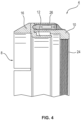
- the Fig. 1 shows a riflescope 2 with an adapter device 4 for attaching an attachment 6 ( Fig. 6 ).
- the adapter device 4 has a clamping ring 8 which is attached to the objective side of the riflescope 2 and which can be mechanically coupled to a separate retaining ring 10.
- the clamping ring 8 has a retaining contour 12 and the retaining ring 10 has a corresponding counter contour 14 ( Fig. 2 ) on.
- contours 12, 14 are designed as threads, so that the mechanical coupling between the adapter parts 8, 10 is realized in particular as a positive and/or non-positive threaded connection.
- the clamping ring 8 has two ring halves 16, 18 that can be clamped against each other like a clamp.
- the ring half 18 is in one piece, i.e. one-piece or monolithic, with the holding contour 12.
- the ring halves 16, 18 encompass the objective-side tube end of the riflescope 2, which is clamped tangentially and radially by the clamping ring 8 in a form-fitting and force-fitting manner when clamped or mounted.
- the ring halves 16, 18 are connected by means of two diametrically opposed fastening screws 15 ( Fig. 5 ) against each other.
- the ring halves 16, 18 each have two diametrically opposed flange areas 20 with a (threaded) bore.
- the ring halves 16, 18 or the surface pressure of the clamping ring 8 have a clamping or contact surface with an axial width of less than 20 mm, in particular less than 17 mm, preferably about 15 mm.
- the holding contour 12 is preferably designed as an external thread of the clamping ring 8 and the counter contour 14 as a corresponding internal thread of the retaining ring 10.
- the contours or threads 12, 14 are preferably designed such that they can be joined together by means of a rotary movement, in particular by means of a 45° rotary movement, of the counter contour 12 or the retaining ring 10.
- the contours 12, 14 are designed as interrupted round threads.
- a fine centering 22 is suitably provided on the clamping ring 8, which absorbs a surface in the thread play as a fitting diameter, so that a repeat accuracy of, for example, ⁇ 0.05 mm is guaranteed by the planar contact of the contours and the fine centering.
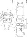
- the adapter device 4 is designed in particular as a mounting adapter which has a retaining ring 10 adapted to a special attachment.
- the retaining ring 10 is provided with an internal thread 24 which can be screwed into a corresponding external thread of the attachment.
- the adapter device 4 of the Figures 2 to 4 further comprises an adjustable locking element 26, by means of which the fastening or locking, i.e. the rotational position of the adapter parts 8, 10 in the assembly position, can be determined.
- the locking element 26 is designed as a spring pressure piece which is integrated in the retaining ring 10.
- the Figures 5 and 6 show a third embodiment of the adapter device 4, not according to the invention.
- the counter contour 14' is designed as a part of the attachment 6.
- the mechanical coupling or joining connection of the adapter device 4 is designed in the manner of a bayonet connection.
- the clamping ring 8 has two radially inwardly projecting pins as a holding contour 12', whereby the counter contour 14' is designed as two radial oblique grooves of the attachment 6.
Landscapes
- Physics & Mathematics (AREA)
- Engineering & Computer Science (AREA)
- General Engineering & Computer Science (AREA)
- Optics & Photonics (AREA)
- General Physics & Mathematics (AREA)
- Mechanical Engineering (AREA)
- Astronomy & Astrophysics (AREA)
- Clamps And Clips (AREA)
- Telescopes (AREA)
Description
- Die Erfindung betrifft eine Adaptervorrichtung zur Befestigung eines Vorsatzgeräts an einem Zielfernrohr.
- Ein Zielfernrohr ist eine fernoptische Einrichtung, welche als eine Primäroptik beispielsweise an einer Schusswaffe montierbar ist. Ein solches Zielfernrohr dient einer optischen Vergrößerung von durch dieses in der Ferne betrachteten Objekten. Hierfür weist das Zielfernrohr einen Tubus mit einem objektseitigen Objektiv und mit einem benutzer- oder augenseitigen Okular auf. Zwischen dem Objektiv und dem Okular ist ein optischer Kanal gebildet, in welchem beispielsweise mehrere optische, insbesondere optisch vergrößernde, Elemente, zum Beispiel Linsen und/oder Prismen, angeordnet sind. In dem optischen Kanal befindet sich typischerweise weiterhin ein Absehen, also eine Zielmarkierung.
- Um bei eingeschränkten oder schlechten Lichtverhältnissen ein zuverlässiges Zielen zu ermöglichen, werden beispielsweise sogenannte Vorsatz- oder Aufsatzgeräte, beispielsweise in Form von Nachtsichtgeräten oder Wärmebildgeräten, eingesetzt, welche vor dem Objektiv des Zielfernrohrs angeordnet werden. Bei einem solchen Vorsatzgerät wird mit dem Zielfernrohr auf ein von dem Vorsatzgerät erzeugtes Bild gezielt. Mit anderen Worten ist das Absehen auf ein Bild ausgerichtet. Dadurch ist es notwendig, dass ein solches Vorsatzgerät möglichst fluchtend mit dem Zielfernrohr angeordnet wird. Dies bedeutet, dass die optischen Achsen oder Kanäle des Zielfernrohrs und des Vorsatzgeräts möglichst versatzfrei aufeinander ausgerichtet sein sollten.
- Typischerweise berühren sich das Vorsatzgerät und das Zielfernrohr beziehungsweise das Objektiv nicht. Hintergrund ist, dass das Vorsatzgerät ein vergleichsweise hohes Baugewicht, beispielsweise zwischen 300 g (Gramm) und 800 g, aufweist, und bei einer Schussabgabe der Schusswaffe durch den Hochschlag einer starken Belastung ausgesetzt ist. Insbesondere ist hierbei eine gleichbleibende, festen Fixierung des Vorsatzgeräts gewünscht, so dass nach einer Schussabgabe kein Versatz zwischen den optischen Achsen auftritt.
- Das Vorsatzgerät kann hierbei beispielsweise mittels einer Montageschiene vor das Zielfernrohr montiert werden. Die Montageschiene ist hierbei insbesondere an der Schusswaffe befestigt.
- Ebenso denkbar ist beispielsweise der Einsatz von Adaptervorrichtungen als Montageadapter, welche als mechanische Schnittstelle zwischen dem Zielfernrohr und dem Vorsatzgerät angeordnet sind. Beispielsweise sind als Klemmringe ausgeführte Adaptervorrichtungen mit einem Schnellverschluss oder Schnellspanner möglich, welche einerseits an einem objektivseitigen Tubusende des Zielfernrohrs und anderseits and dem Vorsatzgerät klemmbefestigbar sind. Das Vorsatzgerät ist somit über die Adaptervorrichtung mittelbar an dem Zielfernrohr befestigt, und wird somit von dem Zielfernrohr getragen.
- In der
WO 99/27318 A1 - Die
DE 20 2020 005 036 U1 offenbart einen Schnellmontageadapter für eine wiederholgenau reproduzierbare Montage von Nach- und Vorsatzanbauten an Zieloptiken. Der Schnellmontageadapter weist eine rohrkörperähnlich ausgestaltete Geometrie auf, welche aus mindestens zwei miteinander korrespondierenden Elementen besteht, welche, durch Einschwenken, mittels hintergreifender und formschlüssig wirkender Geometrien und/oder Verbindungselemente, welche den Elementen anhaften und/oder verstellbar mit den Elementen korrespondieren, eine Verbindung eingehen. - Aus der
DE 20 2019 106 729 U1 ist ein optoelektronisches Gerät zur Verwendung als Monokular und als Vorsatzgerät für optische Einrichtungen bekannt, bei welcher eine Steuereinheit automatisch eine Umschaltung zwischen zwei Anzeigemodi auslöst, wenn von einem Sensorelement eine Rückmeldung gegeben wird, dass das optoelektronische Gerät nicht mehr mit einer optischen Einrichtung verbunden ist. - Der Erfindung liegt die Aufgabe zugrunde, einen besonders geeigneten Adapter zur Befestigung eines optische Vorsatzgeräts an einem Zielfernrohr anzugeben. Insbesondere soll eine möglichst wiederholgenaue exakte Halterung oder Befestigung des Vorsatzgeräts zum Zentrum des Zielfernrohrs (optischen Achse) ermöglicht werden.
- Die Aufgabe wird erfindungsgemäß gelöst mit den Merkmalen des Anspruchs 1. Vorteilhafte Ausgestaltungen und Weiterbildungen sind Gegenstand der Unteransprüche.
- Die erfindungsgemäße Adaptervorrichtung ist zur Befestigung eines Vorsatzgeräts an einem Zielfernrohr vorgesehen, sowie dafür geeignet und eingerichtet. Bei dem Zielfernrohr handelt es sich vorzugsweise um ein an einer Schusswaffe, insbesondere an einer handgeführten Schusswaffe, wie beispielsweise einem Jagdgewehr, befestigtes oder montiertes Zielfernrohr. Das Vorsatz- oder Aufsatzgerät ist beispielsweise als ein Wärmebild- oder Nachtsichtgerät ausgebildet.
- Die Adaptervorrichtung weist hierbei einen an dem Zielfernrohr befestigten oder befestigbaren Klemmring auf, wobei der Klemmring eine Haltekontur zur lösbaren form- und/oder kraftschlüssigen Befestigung, Arretierung, Verrastung oder Verriegelung mit einer an dem Vorsatzgerät angeordneten oder anordenbaren Gegenkontur aufweist.
- Die Konjunktion "und/oder" ist hier und im Folgenden derart zu verstehen, dass die mittels dieser Konjunktion verknüpften Merkmale sowohl gemeinsam als auch als Alternativen zueinander ausgebildet sein können.
- Unter einem "Formschluss" oder einer "formschlüssigen Verbindung" zwischen wenigstens zwei miteinander verbundenen Teilen wird hier und im Folgenden insbesondere verstanden, dass der Zusammenhalt der miteinander verbundenen Teile zumindest in einer Richtung durch ein unmittelbares Ineinandergreifen von Konturen der Teile selbst oder durch ein mittelbares Ineinandergreifen über ein zusätzliches Verbindungsteil erfolgt. Das "Sperren" einer gegenseitigen Bewegung in dieser Richtung erfolgt also formbedingt.
- Unter einem "Kraftschluss" oder einer "kraftschlüssigen Verbindung" zwischen wenigstens zwei miteinander verbundenen Teilen wird hier und im Folgenden insbesondere verstanden, dass die miteinander verbundenen Teile aufgrund einer zwischen ihnen wirkenden Reibkraft gegen ein Abgleiten aneinander gehindert sind. Fehlt eine diese Reibkraft hervorrufende "Verbindungskraft" (dies bedeutet diejenige Kraft, welche die Teile gegeneinander drückt, beispielsweise eine Schraubenkraft oder die Gewichtskraft selbst), kann die kraftschlüssige Verbindung nicht aufrecht erhalten und somit gelöst werden.
- Durch die Adaptervorrichtung ist somit eine zerstörungsfreie und wiederholgenaue Befestigung des Vorsatzgeräts am Zielfernrohr ermöglicht. Insbesondere ist es möglich die optischen Achsen von Zielfernrohr und Vorsatzgerät reproduzierbar möglichst versatzfrei zueinander anzuordnen. Mit anderen Worten ermöglicht die Adaptervorrichtung eine wiederholgenaue präzise Ausrichtung des Sehfeldes des Vorsatzgerätes mit dem Mittelpunkt des Sehfeldes des Zielfernrohrs, so dass stets eine optimale Beobachtungsposition realisiert wird. Dadurch ist eine besonders geeignete Adaptervorrichtung realisiert.
- Die Haltekontur und Gegenkontur können hierbei - ohne Beschränkung der Allgemeinheit - beispielsweise als eine Gewindeverbindung, eine Bajonettverbindung, oder als eine Schwertverriegelung ausgeführt sein. Wesentlich ist, dass eine zerstörungsfrei lösbare, form- und/oder kraftschlüssige, Fügeverbindung realisierbar ist.
- Unter "axial" oder einer "Axialrichtung" wird hier und im Folgenden insbesondere eine Richtung parallel (koaxial) zur optischen Achse beziehungsweise entlang einer Längsrichtung des Zielfernrohrs, also senkrecht zu den Stirnseiten des etwa zylindrischen Tubus verstanden. Entsprechend wird hier und im Folgenden unter "radial" oder einer "Radialrichtung" insbesondere eine senkrecht (quer) zur optischen Achse des Zielfernrohrs orientierte Richtung entlang eines Radius des Zielfernrohrs oder Tubus verstanden. Unter "tangential" oder einer "Tangentialrichtung" wird hier und im Folgenden insbesondere eine Richtung entlang des Umfangs des Zielfernrohrs oder Tubus (Umfangsrichtung, Azimutalrichtung), also eine Richtung senkrecht zur Axialrichtung und zur Radialrichtung, verstanden.
- Die Adaptervorrichtung kann hierbei beispielsweise als ein spezieller Montageadapter ausgeführt sein, dessen Haltekontur an eine vorgegebene Gegenkontur des Vorsatzgeräts angepasst ist. In einer erfindungsgemäßen Ausführung weist die Adaptervorrichtung jedoch einen an dem Vorsatzgerät befestigbaren Haltering auf, welcher mit der Gegenkontur versehen ist. Der Haltering kann hierbei für verschiedenste Vorsatzgeräte hergestellt werden. Der Haltering ist hierbei an eine jeweilige Verriegelungsart des Vorsatzgeräts angepasst. Beispielsweise weist der Haltering einen an ein Befestigungsgewinde des Vorsatzgeräts Gewindedurchmesser auf. Dadurch ist es möglich das Vorsatzgerät mittels des Halterings für eine Befestigung an dem Klemmring nachzurüsten, der Haltering wirkt somit quasi als ein Adapterring für die Adaptervorrichtung. Insbesondere ist es somit möglich ohne einen Wechsel oder Austausch des Halterings das Vorsatzgerät an verschiedensten Zielfernrohren zu montieren, wobei ein erneutes Einschießen nicht notwendig ist.
- In einer denkbaren Weiterbildung weist der Klemmring zwei schellenartig gegeneinander verspannbare Ringhälften oder Halbschalen auf. Die Ringhälften umgreifen hierbei ein objektivseitiges Tubusende des Zielfernrohrs, welches im verspannten oder montierten Zustand form- und kraftschlüssig von dem Klemmring tangential und radial geklemmt ist. Dadurch ist eine einfache und zerstörungsfrei lösbare Befestigung des Klemmrings an dem Zielfernrohr ermöglicht.
- In einer denkbaren Ausgestaltung sind die Ringhälften beispielsweise mittels zweier etwa diametral gegenüberliegender Befestigungsschrauben gegeneinander verspannbar. Beispielsweise weisen die Ringhälften hierbei jeweils zwei diametral gegenüberliegende Flanschbereiche mit einer (Gewinde-)Bohrung auf, wobei die Flanschbereiche der Ringhälften übereinander fluchtend angeordnet werden. Dadurch ist eine einfache und aufwandreduzierte Klemmbefestigung an dem Zielfernrohr realisiert.
- Der Klemmring wird somit mittels zweier Befestigungsschrauben über eine Flächenpressung der Ringhälften an dem Zielfernrohr montiert. Dadurch ist weiterhin eine einfache Anpassung des Klemmrings an Zielfernrohre mit unterschiedlichem (Tubus-)Durchmessern möglich. In einer besonders vorteilhaften Ausbildung weisen die Ringhälften beziehungsweise die Flächenpressung eine Spann- oder Anlagefläche mit einer axialen Breite von weniger als 20 mm (Millimeter), insbesondere weniger als 17 mm, vorzugsweise etwa 15 mm, auf. Mit anderen Worten wird beispielsweise lediglich eine Spannfläche mit 15 mm Breite benötigt. Dies hat zur Folge, dass ebenso kombinierte Waffen wie ein Drilling oder eine Bockbüchsflinte mit einem Vorsatzgerät verwendet werden können.
- Gemäß der Erfindung ist vorgesehen, dass die Haltekontur des Klemmrings und die Gegenkontur des Halterings als eine Gewindeverbindung ausgeführt sind. Beispielsweise ist die Haltekontur hierbei als ein Außengewinde und die Gegenkontur als ein korrespondierendes Innengewinde ausgeführt.
- Vorzugsweise sind die Haltekontur und die Gegenkontur derart ausgeführt sind, dass sie über eine Drehbewegung, insbesondere mittels einer 45°-Drehbewegung, der Gegenkontur beziehungsweise des Halterings miteinander fügbar sind. Hierzu sind die Haltekontur und die Gegenkontur in der erfindungsgemäßen Ausführung als unterbrochene Rundgewinde ausgeführt. Geeigneterweise ist hierbei eine Feinzentrierung, beispielsweise am Klemmring vorgesehen, welche als Passungsdurchmesser eine Fläche im Gewindespiel abfängt, so dass durch die Plananlage der Konturen und der Feinzentrierung eine Wiederholgenauigkeit von beispielsweise ± 0.05 mm gewährleistet ist.
- In einer zweckmäßigen Weiterbildung weist die Adaptervorrichtung ein einstellbares Verriegelungselement, beispielsweise einen betätigbaren Verriegelungsstift auf, welches(r) eine relative Bewegung der Konturen blockiert. Der Verriegelungsstift ist hierbei beispielsweise an dem Klemmring und/oder an dem Haltering angeordnet. Bei der erfindungsgemäßen Ausführung der Konturen als unterbrochene Rundgewinde greift der Verriegelungsstift hierbei beispielsweise in einen durch die Unterbrechungen gebildeten Zwischenraum ein. Damit ist eine stets gleichbleibende Position (Rotation) bei der Befestigung des Vorsatzgeräts an dem Klemmring sichergestellt. Beispielsweise weist der Haltering einen Verriegelungsstift auf der durch drücken eines Hebels entriegelt wird.
- In einer alternativen, nicht erfindungsgemäßen, Ausgestaltung sind die Haltekontur und die Gegenkontur nach Art einer Bajonett-Verbindung ausgeführt. In einer denkbaren Ausführung ist die Haltekontur hierbei als zwei emporstehende Stifte ausgeführt, welche an diametral gegenüberliegenden Stellen des Klemmrings radial nach innen gerichtet sind, und wobei die Gegenkontur als zwei radiale Schrägnuten ausgeführt ist. Dadurch ist eine besonders kurze Bauform der Adaptervorrichtung realisiert.
- Nachfolgend sind Ausführungsbeispiele der Erfindung anhand einer Zeichnung näher erläutert. Darin zeigen:
- Fig. 1
- in perspektivischer Darstellung ein Zielfernrohr mit einer Adaptervorrichtung mit einem Haltering und mit einem Klemmring,
- Fig. 2, Fig. 3
- in perspektivischen Darstellungen eine Adaptervorrichtung in einer zweiten Ausführungsform
- Fig. 4
- in Schnittansicht die Adaptervorrichtung gemäß der zweiten Ausführungsform, und
- Fig. 5, Fig. 6
- in perspektivischen Darstellungen eine dritte, nicht erfindungsgemäße, Ausführungsform der Adaptervorrichtung.
- Einander entsprechende Teile und Größen sind in allen Figuren stets mit den gleichen Bezugszeichen versehen.
- Die
Fig. 1 zeigt ein Zielfernrohr 2 mit einer Adaptervorrichtung 4 zur Befestigung eines Vorsatzgeräts 6 (Fig. 6 ). Die Adaptervorrichtung 4 weist einen an dem Zielfernrohr 2 objektivseitig befestigten Klemmring 8 auf, welcher mit einem separaten Haltering 10 mechanisch koppelbar ist. Hierzu weist der Klemmring 8 eine Haltekontur 12 und der Haltering 10 eine korrespondierende Gegenkontur 14 (Fig. 2 ) auf. - In dem Ausführungsbeispiel der
Fig. 1 ist sind die Konturen 12, 14 als Gewinde ausgeführt, so dass die mechanische Kopplung zwischen den Adapterteilen 8, 10 insbesondere als eine form- und/oder kraftschlüssige Gewindeverbindung realisiert ist. - Der Klemmring 8 weist zwei schellenartig gegeneinander verspannbare Ringhälften 16, 18 auf. Die Ringhälfte 18 ist hierbei einteilig, also einstückig oder monolithisch, mit der Haltekontur 12 ausgeführt. Die Ringhälften 16, 18 umgreifen hierbei das objektivseitige Tubusende des Zielfernrohrs 2, welches im verspannten oder montierten Zustand form- und kraftschlüssig von dem Klemmring 8 tangential und radial geklemmt ist. Die Ringhälften 16, 18 sind hierbei mittels zweier diametral gegenüberliegender Befestigungsschrauben 15 (
Fig. 5 ) gegeneinander verspannbar. Die Ringhälften 16, 18 weisen hierbei jeweils zwei diametral gegenüberliegende Flanschbereiche 20 mit einer (Gewinde-)Bohrung auf. - Die Ringhälften 16, 18 beziehungsweise die Flächenpressung des Klemmrings 8 weisen hierbei eine Spann- oder Anlagefläche mit einer axialen Breite von weniger als 20 mm, insbesondere weniger als 17 mm, vorzugsweise etwa 15 mm, auf.
- Die Haltekontur 12 ist vorzugsweise als ein Außengewinde des Klemmrings 8 und die Gegenkontur 14 als ein korrespondierendes Innengewinde des Halterings 10 ausgeführt. Vorzugsweise sind die Konturen oder Gewinde 12, 14 derart ausgeführt sind, dass sie über eine Drehbewegung, insbesondere mittels einer 45°-Drehbewegung, der Gegenkontur 12 beziehungsweise des Halterings 10 miteinander fügbar sind. Hierzu sind die Konturen 12, 14 als unterbrochene Rundgewinde ausgeführt. Geeigneterweise ist hierbei eine Feinzentrierung 22, am Klemmring 8 vorgesehen, welche als Passungsdurchmesser eine Fläche im Gewindespiel abfängt, so dass durch die Plananlage der Konturen und der Feinzentrierung eine Wiederholgenauigkeit von beispielsweise ± 0.05 mm gewährleistet ist.
- Nachfolgend ist anhand der
Figuren 2 bis 4 ein zweites Ausführungsbeispiel der Adaptervorrichtung 4 näher erläutert. In dieser Ausführung ist die Adaptervorrichtung 4 insbesondere als ein Montageadapter ausgeführt, der einen an ein spezielles Vorsatzgerät angepassten Haltering 10 aufweist. Der Haltering 10 ist hierbei mit einem Innengewinde 24 versehen, welches in ein korrespondierendes Außengewinde des Vorsatzgeräts eindrehbar ist. - Die Adaptervorrichtung 4 der
Figuren 2 bis 4 weist weiterhin ein einstellbares Verriegelungselement 26 auf, mittels welchem die Befestigung oder Arretierung, also die Rotationsposition der Adapterteile 8, 10 in der Montagestellung, festlegbar ist. In dieser Ausführungsform ist das Verriegelungselement 26 als ein Federdruckstück ausgebildet, welches in dem Haltering 10 integriert ist. - Die
Figuren 5 und 6 zeigen ein nicht erfindungsgemäßes drittes Ausführungsbeispiel der Adaptervorrichtung 4. In dieser Ausgestaltung ist die Gegenkontur 14' als ein Teil des Vorsatzgeräts 6 ausgeführt. Die mechanische Kopplung oder Fügeverbindung der Adaptervorrichtung 4 ist hierbei nach Art einer Bajonett-Verbindung ausgeführt. Hierzu weist der Klemmring 8 zwei am Innenumfang radial nach innen ragende Stifte als Haltekontur 12 ` auf, wobei die Gegenkontur 14' als zwei radiale Schrägnuten des Vorsatzgeräts 6 ausgeführt sind. - Die Erfindung ist nicht auf die vorstehend beschriebenen Ausführungsbeispiele beschränkt. Vielmehr können auch andere Varianten der Erfindung von dem Fachmann hieraus abgeleitet werden, ohne den Gegenstand der Erfindung zu verlassen. Insbesondere sind ferner alle im Zusammenhang mit den Ausführungsbeispielen beschriebenen Einzelmerkmale auch auf andere Weise miteinander kombinierbar, ohne den Gegenstand der Erfindung zu verlassen. In jedem Fall wird der Gegenstand der Erfindung durch die beigefügten Ansprüche definiert.
-
- 2
- Zielfernrohr
- 4
- Adaptervorrichtung
- 6
- Vorsatzgerät
- 8
- Klemmring
- 10
- Haltering
- 12, 12'
- Haltekontur
- 14, 14'
- Gegenkontur
- 15
- Befestigungsschrauben
- 16
- Ringhälfte
- 18
- Ringhälfte
- 20
- Flanschbereich
- 22
- Feinzentrierung
- 24
- Innengewinde
- 26
- Verriegelungselement
Claims (6)
- Adaptervorrichtung (4) zur Befestigung eines Vorsatzgeräts (6) an einem Zielfernrohr (2), aufweisend einen an dem Zielfernrohr (2) befestigbaren Klemmring (8) und einen an dem Vorsatzgerät (6) befestigbaren Haltering (10),- wobei der Klemmring (8) eine Haltekontur (12) zur lösbaren form- und/oder kraftschlüssigen Befestigung mit einer an dem Haltering (10) angeordneten Gegenkontur (14) aufweist,- die Haltekontur (12) und die Gegenkontur (14) als eine Gewindeverbindung mit einem unterbrochenen Rundgewinde ausgeführt sind.
- Adaptervorrichtung (4) nach Anspruch 1,
dadurch gekennzeichnet,
dass der Klemmring (8) zwei schellenartig gegeneinander verspannbare Ringhälften (16, 18) aufweist. - Adaptervorrichtung (4) nach Anspruch 2,
dadurch gekennzeichnet,
dass die Ringhälften (16, 18) mittels zweier diametral gegenüberliegender Befestigungsschrauben (15) gegeneinander verspannbar sind. - Adaptervorrichtung (4) nach Anspruch 2 oder 3,
dadurch gekennzeichnet,
dass die Ringhälften (16, 18) eine Spannfläche zur Halterung an dem Zielfernrohr (2) mit einer axialen Breite von weniger als 20 mm, insbesondere von etwa 15 mm, aufweisen. - Adaptervorrichtung (4) nach Anspruch 1 bis 4,
dadurch gekennzeichnet,
dass die Haltekontur (12) als ein Außengewinde und die Gegenkontur (14) als ein korrespondierendes Innengewinde ausgeführt sind. - Adaptervorrichtung (4) nach einem der Ansprüche 1 bis 5,
dadurch gekennzeichnet,
dass der Haltering (10) und/oder der Klemmring (8) ein einstellbares Verriegelungselement (26) aufweist.
Applications Claiming Priority (1)
| Application Number | Priority Date | Filing Date | Title |
|---|---|---|---|
| DE102021200186.6A DE102021200186A1 (de) | 2021-01-11 | 2021-01-11 | Adaptervorrichtung zur Befestigung eines Vorsatzgeräts an einem Zielfernrohr |
Publications (2)
| Publication Number | Publication Date |
|---|---|
| EP4027101A1 EP4027101A1 (de) | 2022-07-13 |
| EP4027101B1 true EP4027101B1 (de) | 2025-01-01 |
Family
ID=78821917
Family Applications (1)
| Application Number | Title | Priority Date | Filing Date |
|---|---|---|---|
| EP21212363.2A Active EP4027101B1 (de) | 2021-01-11 | 2021-12-03 | Adaptervorrichtung zur befestigung eines vorsatzgeräts an einem zielfernrohr |
Country Status (4)
| Country | Link |
|---|---|
| US (1) | US20220221248A1 (de) |
| EP (1) | EP4027101B1 (de) |
| CA (1) | CA3145128A1 (de) |
| DE (1) | DE102021200186A1 (de) |
Families Citing this family (2)
| Publication number | Priority date | Publication date | Assignee | Title |
|---|---|---|---|---|
| DE102023112633A1 (de) | 2023-05-12 | 2024-11-14 | EP Arms GmbH | Zielvorrichtung für eine Schusswaffe |
| CN117908243B (zh) * | 2024-03-12 | 2024-06-07 | 东华大学 | 多视场望远系统 |
Family Cites Families (15)
| Publication number | Priority date | Publication date | Assignee | Title |
|---|---|---|---|---|
| US5299067A (en) * | 1992-12-15 | 1994-03-29 | Markzmen Optics | Auxiliary lens attachment |
| DE9402732U1 (de) | 1994-02-19 | 1995-03-30 | Horst Blaser Jagdwaffenfabrik, 88316 Isny | Zielfernrohr für ein Gewehr |
| US5444507A (en) * | 1994-03-22 | 1995-08-22 | Itt Corporation | Device for coupling night vision assembly to a video camcorder |
| US5937562A (en) * | 1997-11-17 | 1999-08-17 | Henry Technical Services, Incorporated | Optical accessory |
| US6310721B2 (en) | 1998-12-11 | 2001-10-30 | International Technologies (Lasers) Ltd. | Night vision monocular |
| WO2005031395A2 (en) * | 2003-09-23 | 2005-04-07 | Richard Brough | Optical viewing system and adaptor therefor |
| US7870688B1 (en) * | 2006-02-03 | 2011-01-18 | Night Optics USA, Inc. | Clamping device for coaxially coupling optical devices |
| CN101553192B (zh) * | 2006-09-15 | 2013-07-17 | 奥瑟Hf公司 | 减小假体产品造型高度的方法和设备 |
| US9335536B2 (en) * | 2011-06-20 | 2016-05-10 | Yoachim C. Russ | Visual target acquisition scope system |
| AT513008B1 (de) * | 2012-06-11 | 2021-02-15 | Swarovski Optik Kg | Adapterhülse für Beobachtungsfernrohr |
| DE202019106729U1 (de) | 2019-12-03 | 2020-02-24 | Matthias Ruckdeschel | Optoelektronisches Gerät und System aus optoelektronischem Gerät und optischer Einrichtung |
| GB2597959B (en) * | 2020-08-11 | 2023-02-22 | Jsc Yukon Advanced Optics Worldwide | Mounting apparatus and method for night vision device |
| DE202020005036U1 (de) | 2020-11-13 | 2021-01-07 | Damian Hellmann | Schnellmontageadapter für eine wiederholgenau reproduzierbare Montage von Nach- und Vorsatzanbauten an Zieloptiken |
| DE202021000644U1 (de) | 2021-02-19 | 2021-03-31 | D&M Jagdausrüster GbR (vertretungsber. Gesellschafter: David & Mathias Kirchhöfer, 27367 Sottrum) | Nachtsicht-Vorsatzgerät-Klemmadapter, Nachtsicht-Vorsatzgerät-Klemmadapter-System mit demselben sowie Schusswaffe mit dem Nachtsicht-Vorsatzgerät-Klemmadapter-System |
| DE102023106781A1 (de) * | 2023-03-17 | 2024-09-19 | Präzise Jagen GmbH | Erster Befestigungsring mit axialer Klemmung für eine Adaptervorrichtung zur Befestigung eines ersten Rohrabschnittes an einem zweiten Rohrabschnitt sowie Adaptervorrichtung |
-
2021
- 2021-01-11 DE DE102021200186.6A patent/DE102021200186A1/de not_active Withdrawn
- 2021-12-03 EP EP21212363.2A patent/EP4027101B1/de active Active
-
2022
- 2022-01-10 CA CA3145128A patent/CA3145128A1/en active Pending
- 2022-01-11 US US17/572,869 patent/US20220221248A1/en not_active Abandoned
Also Published As
| Publication number | Publication date |
|---|---|
| CA3145128A1 (en) | 2022-07-11 |
| DE102021200186A1 (de) | 2022-07-14 |
| EP4027101A1 (de) | 2022-07-13 |
| US20220221248A1 (en) | 2022-07-14 |
Similar Documents
| Publication | Publication Date | Title |
|---|---|---|
| DE4339397C2 (de) | Zielfernrohr | |
| EP4027101B1 (de) | Adaptervorrichtung zur befestigung eines vorsatzgeräts an einem zielfernrohr | |
| DE102017205590B3 (de) | Justierbarer Faserkollimator und Verfahren zu dessen Montage | |
| EP3315893B1 (de) | Zielfernrohr mit verstellhilfe | |
| EP2080050A1 (de) | Vorrichtung zum einkoppeln von licht in eine lichtleitfaser | |
| DE2239661A1 (de) | Vorrichtung zum erzeugen eines mit der mittelachse eines gewehrlaufs fluchtenden richtpunktes | |
| EP2345866B1 (de) | Parallaxefreies Zielfernrohr | |
| DE20022471U1 (de) | Nachrüstgerät für ein Zielfernrohr | |
| EP3553457A1 (de) | Vorrichtung zur variablen befestigung zweier optikeinrichtungen an einer waffe | |
| AT521537A2 (de) | Gefaltete relaisfeder für ein optisches visier | |
| DE112019006818B4 (de) | Optisches visier | |
| AT516975B1 (de) | Zielfernrohr mit Verstellvorrichtung | |
| DE102010005588A1 (de) | Zielfernrohrmontagesystem für eine Feuerwaffe | |
| DE202020005036U1 (de) | Schnellmontageadapter für eine wiederholgenau reproduzierbare Montage von Nach- und Vorsatzanbauten an Zieloptiken | |
| EP2738511A1 (de) | Zubehöradapter für eine vereinfachte Zielfindung | |
| DE102021108266B4 (de) | Adaptervorrichtung zur Befestigung eines Zusatzgerätes sowie Befestigungsringe einer Adaptervorrichtung | |
| EP0189001A1 (de) | Verfahren und Vorrichtung zum Ausrichten einer Feuerwaffenlaufachse | |
| DE102023112633A1 (de) | Zielvorrichtung für eine Schusswaffe | |
| DE202018101992U1 (de) | Vorrichtung zur variablen Befestigung zweier Optikeinrichtungen an einer Waffe | |
| DE102020006956A1 (de) | Schnellmontageadapter für eine wiederholgenau reproduzierbare Montage von Nach- und Vorsatzanbauten an Zieloptiken | |
| DE19500829C1 (de) | Zusatzgerät für ein Zielfernrohr für Gewehre zur Veränderung der Vergrößerung | |
| AT402449B (de) | Verstellbare montagevorrichtung für visiereinrichtungen auf waffen | |
| EP3851785B1 (de) | Stellvorrichtung mit verstellbarem indikatorelement und zielfernrohr mit selbiger | |
| DE102019127127B4 (de) | Montagevorrichtung für ein Zielgerät | |
| AT527713A1 (de) | Zielfernrohrsystem |
Legal Events
| Date | Code | Title | Description |
|---|---|---|---|
| PUAI | Public reference made under article 153(3) epc to a published international application that has entered the european phase |
Free format text: ORIGINAL CODE: 0009012 |
|
| STAA | Information on the status of an ep patent application or granted ep patent |
Free format text: STATUS: THE APPLICATION HAS BEEN PUBLISHED |
|
| AK | Designated contracting states |
Kind code of ref document: A1 Designated state(s): AL AT BE BG CH CY CZ DE DK EE ES FI FR GB GR HR HU IE IS IT LI LT LU LV MC MK MT NL NO PL PT RO RS SE SI SK SM TR |
|
| STAA | Information on the status of an ep patent application or granted ep patent |
Free format text: STATUS: REQUEST FOR EXAMINATION WAS MADE |
|
| 17P | Request for examination filed |
Effective date: 20230112 |
|
| RBV | Designated contracting states (corrected) |
Designated state(s): AL AT BE BG CH CY CZ DE DK EE ES FI FR GB GR HR HU IE IS IT LI LT LU LV MC MK MT NL NO PL PT RO RS SE SI SK SM TR |
|
| P01 | Opt-out of the competence of the unified patent court (upc) registered |
Effective date: 20230911 |
|
| GRAP | Despatch of communication of intention to grant a patent |
Free format text: ORIGINAL CODE: EPIDOSNIGR1 |
|
| STAA | Information on the status of an ep patent application or granted ep patent |
Free format text: STATUS: GRANT OF PATENT IS INTENDED |
|
| INTG | Intention to grant announced |
Effective date: 20240812 |
|
| RIC1 | Information provided on ipc code assigned before grant |
Ipc: F41G 1/38 20060101ALI20240802BHEP Ipc: G03B 17/48 20210101ALI20240802BHEP Ipc: G03B 17/56 20210101ALI20240802BHEP Ipc: G02B 23/16 20060101ALI20240802BHEP Ipc: F41G 11/00 20060101AFI20240802BHEP |
|
| GRAS | Grant fee paid |
Free format text: ORIGINAL CODE: EPIDOSNIGR3 |
|
| GRAA | (expected) grant |
Free format text: ORIGINAL CODE: 0009210 |
|
| STAA | Information on the status of an ep patent application or granted ep patent |
Free format text: STATUS: THE PATENT HAS BEEN GRANTED |
|
| AK | Designated contracting states |
Kind code of ref document: B1 Designated state(s): AL AT BE BG CH CY CZ DE DK EE ES FI FR GB GR HR HU IE IS IT LI LT LU LV MC MK MT NL NO PL PT RO RS SE SI SK SM TR |
|
| REG | Reference to a national code |
Ref country code: GB Ref legal event code: FG4D Free format text: NOT ENGLISH |
|
| REG | Reference to a national code |
Ref country code: DE Ref legal event code: R096 Ref document number: 502021006266 Country of ref document: DE |
|
| REG | Reference to a national code |
Ref country code: CH Ref legal event code: EP |
|
| REG | Reference to a national code |
Ref country code: IE Ref legal event code: FG4D Free format text: LANGUAGE OF EP DOCUMENT: GERMAN |
|
| REG | Reference to a national code |
Ref country code: LT Ref legal event code: MG9D |
|
| REG | Reference to a national code |
Ref country code: NL Ref legal event code: MP Effective date: 20250101 |
|
| PG25 | Lapsed in a contracting state [announced via postgrant information from national office to epo] |
Ref country code: NL Free format text: LAPSE BECAUSE OF FAILURE TO SUBMIT A TRANSLATION OF THE DESCRIPTION OR TO PAY THE FEE WITHIN THE PRESCRIBED TIME-LIMIT Effective date: 20250101 |
|
| PG25 | Lapsed in a contracting state [announced via postgrant information from national office to epo] |
Ref country code: FI Free format text: LAPSE BECAUSE OF FAILURE TO SUBMIT A TRANSLATION OF THE DESCRIPTION OR TO PAY THE FEE WITHIN THE PRESCRIBED TIME-LIMIT Effective date: 20250101 |
|
| PG25 | Lapsed in a contracting state [announced via postgrant information from national office to epo] |
Ref country code: PL Free format text: LAPSE BECAUSE OF FAILURE TO SUBMIT A TRANSLATION OF THE DESCRIPTION OR TO PAY THE FEE WITHIN THE PRESCRIBED TIME-LIMIT Effective date: 20250101 |
|
| PG25 | Lapsed in a contracting state [announced via postgrant information from national office to epo] |
Ref country code: ES Free format text: LAPSE BECAUSE OF FAILURE TO SUBMIT A TRANSLATION OF THE DESCRIPTION OR TO PAY THE FEE WITHIN THE PRESCRIBED TIME-LIMIT Effective date: 20250101 |
|
| PG25 | Lapsed in a contracting state [announced via postgrant information from national office to epo] |
Ref country code: NO Free format text: LAPSE BECAUSE OF FAILURE TO SUBMIT A TRANSLATION OF THE DESCRIPTION OR TO PAY THE FEE WITHIN THE PRESCRIBED TIME-LIMIT Effective date: 20250401 Ref country code: IS Free format text: LAPSE BECAUSE OF FAILURE TO SUBMIT A TRANSLATION OF THE DESCRIPTION OR TO PAY THE FEE WITHIN THE PRESCRIBED TIME-LIMIT Effective date: 20250501 |
|
| PG25 | Lapsed in a contracting state [announced via postgrant information from national office to epo] |
Ref country code: HR Free format text: LAPSE BECAUSE OF FAILURE TO SUBMIT A TRANSLATION OF THE DESCRIPTION OR TO PAY THE FEE WITHIN THE PRESCRIBED TIME-LIMIT Effective date: 20250101 |
|
| PG25 | Lapsed in a contracting state [announced via postgrant information from national office to epo] |
Ref country code: LV Free format text: LAPSE BECAUSE OF FAILURE TO SUBMIT A TRANSLATION OF THE DESCRIPTION OR TO PAY THE FEE WITHIN THE PRESCRIBED TIME-LIMIT Effective date: 20250101 Ref country code: PT Free format text: LAPSE BECAUSE OF FAILURE TO SUBMIT A TRANSLATION OF THE DESCRIPTION OR TO PAY THE FEE WITHIN THE PRESCRIBED TIME-LIMIT Effective date: 20250502 |
|
| PG25 | Lapsed in a contracting state [announced via postgrant information from national office to epo] |
Ref country code: GR Free format text: LAPSE BECAUSE OF FAILURE TO SUBMIT A TRANSLATION OF THE DESCRIPTION OR TO PAY THE FEE WITHIN THE PRESCRIBED TIME-LIMIT Effective date: 20250402 Ref country code: BG Free format text: LAPSE BECAUSE OF FAILURE TO SUBMIT A TRANSLATION OF THE DESCRIPTION OR TO PAY THE FEE WITHIN THE PRESCRIBED TIME-LIMIT Effective date: 20250101 |
|
| PG25 | Lapsed in a contracting state [announced via postgrant information from national office to epo] |
Ref country code: CZ Free format text: LAPSE BECAUSE OF FAILURE TO SUBMIT A TRANSLATION OF THE DESCRIPTION OR TO PAY THE FEE WITHIN THE PRESCRIBED TIME-LIMIT Effective date: 20250101 |
|
| PG25 | Lapsed in a contracting state [announced via postgrant information from national office to epo] |
Ref country code: SE Free format text: LAPSE BECAUSE OF FAILURE TO SUBMIT A TRANSLATION OF THE DESCRIPTION OR TO PAY THE FEE WITHIN THE PRESCRIBED TIME-LIMIT Effective date: 20250101 |
|
| REG | Reference to a national code |
Ref country code: DE Ref legal event code: R097 Ref document number: 502021006266 Country of ref document: DE |
|
| PG25 | Lapsed in a contracting state [announced via postgrant information from national office to epo] |
Ref country code: SM Free format text: LAPSE BECAUSE OF FAILURE TO SUBMIT A TRANSLATION OF THE DESCRIPTION OR TO PAY THE FEE WITHIN THE PRESCRIBED TIME-LIMIT Effective date: 20250101 |
|
| PG25 | Lapsed in a contracting state [announced via postgrant information from national office to epo] |
Ref country code: DK Free format text: LAPSE BECAUSE OF FAILURE TO SUBMIT A TRANSLATION OF THE DESCRIPTION OR TO PAY THE FEE WITHIN THE PRESCRIBED TIME-LIMIT Effective date: 20250101 |
|
| PG25 | Lapsed in a contracting state [announced via postgrant information from national office to epo] |
Ref country code: IT Free format text: LAPSE BECAUSE OF FAILURE TO SUBMIT A TRANSLATION OF THE DESCRIPTION OR TO PAY THE FEE WITHIN THE PRESCRIBED TIME-LIMIT Effective date: 20250101 |
|
| PG25 | Lapsed in a contracting state [announced via postgrant information from national office to epo] |
Ref country code: EE Free format text: LAPSE BECAUSE OF FAILURE TO SUBMIT A TRANSLATION OF THE DESCRIPTION OR TO PAY THE FEE WITHIN THE PRESCRIBED TIME-LIMIT Effective date: 20250101 |
|
| PG25 | Lapsed in a contracting state [announced via postgrant information from national office to epo] |
Ref country code: RO Free format text: LAPSE BECAUSE OF FAILURE TO SUBMIT A TRANSLATION OF THE DESCRIPTION OR TO PAY THE FEE WITHIN THE PRESCRIBED TIME-LIMIT Effective date: 20250101 |
|
| PG25 | Lapsed in a contracting state [announced via postgrant information from national office to epo] |
Ref country code: SK Free format text: LAPSE BECAUSE OF FAILURE TO SUBMIT A TRANSLATION OF THE DESCRIPTION OR TO PAY THE FEE WITHIN THE PRESCRIBED TIME-LIMIT Effective date: 20250101 |
|
| PLBE | No opposition filed within time limit |
Free format text: ORIGINAL CODE: 0009261 |
|
| STAA | Information on the status of an ep patent application or granted ep patent |
Free format text: STATUS: NO OPPOSITION FILED WITHIN TIME LIMIT |
|
| 26N | No opposition filed |
Effective date: 20251002 |