EP4027088A1 - Vacuum insulated refrigerator structure with feature for controlling deformation and improved air withdrawal - Google Patents
Vacuum insulated refrigerator structure with feature for controlling deformation and improved air withdrawal Download PDFInfo
- Publication number
- EP4027088A1 EP4027088A1 EP22150821.1A EP22150821A EP4027088A1 EP 4027088 A1 EP4027088 A1 EP 4027088A1 EP 22150821 A EP22150821 A EP 22150821A EP 4027088 A1 EP4027088 A1 EP 4027088A1
- Authority
- EP
- European Patent Office
- Prior art keywords
- cover member
- vacuum
- refrigerator
- stepped
- vacuum insulated
- Prior art date
- Legal status (The legal status is an assumption and is not a legal conclusion. Google has not performed a legal analysis and makes no representation as to the accuracy of the status listed.)
- Granted
Links
Images


Classifications
-
- F—MECHANICAL ENGINEERING; LIGHTING; HEATING; WEAPONS; BLASTING
- F16—ENGINEERING ELEMENTS AND UNITS; GENERAL MEASURES FOR PRODUCING AND MAINTAINING EFFECTIVE FUNCTIONING OF MACHINES OR INSTALLATIONS; THERMAL INSULATION IN GENERAL
- F16L—PIPES; JOINTS OR FITTINGS FOR PIPES; SUPPORTS FOR PIPES, CABLES OR PROTECTIVE TUBING; MEANS FOR THERMAL INSULATION IN GENERAL
- F16L59/00—Thermal insulation in general
- F16L59/06—Arrangements using an air layer or vacuum
- F16L59/065—Arrangements using an air layer or vacuum using vacuum
-
- F—MECHANICAL ENGINEERING; LIGHTING; HEATING; WEAPONS; BLASTING
- F25—REFRIGERATION OR COOLING; COMBINED HEATING AND REFRIGERATION SYSTEMS; HEAT PUMP SYSTEMS; MANUFACTURE OR STORAGE OF ICE; LIQUEFACTION SOLIDIFICATION OF GASES
- F25D—REFRIGERATORS; COLD ROOMS; ICE-BOXES; COOLING OR FREEZING APPARATUS NOT OTHERWISE PROVIDED FOR
- F25D23/00—General constructional features
-
- F—MECHANICAL ENGINEERING; LIGHTING; HEATING; WEAPONS; BLASTING
- F25—REFRIGERATION OR COOLING; COMBINED HEATING AND REFRIGERATION SYSTEMS; HEAT PUMP SYSTEMS; MANUFACTURE OR STORAGE OF ICE; LIQUEFACTION SOLIDIFICATION OF GASES
- F25D—REFRIGERATORS; COLD ROOMS; ICE-BOXES; COOLING OR FREEZING APPARATUS NOT OTHERWISE PROVIDED FOR
- F25D23/00—General constructional features
- F25D23/06—Walls
- F25D23/062—Walls defining a cabinet
-
- F—MECHANICAL ENGINEERING; LIGHTING; HEATING; WEAPONS; BLASTING
- F25—REFRIGERATION OR COOLING; COMBINED HEATING AND REFRIGERATION SYSTEMS; HEAT PUMP SYSTEMS; MANUFACTURE OR STORAGE OF ICE; LIQUEFACTION SOLIDIFICATION OF GASES
- F25D—REFRIGERATORS; COLD ROOMS; ICE-BOXES; COOLING OR FREEZING APPARATUS NOT OTHERWISE PROVIDED FOR
- F25D23/00—General constructional features
- F25D23/06—Walls
- F25D23/062—Walls defining a cabinet
- F25D23/063—Walls defining a cabinet formed by an assembly of panels
-
- F—MECHANICAL ENGINEERING; LIGHTING; HEATING; WEAPONS; BLASTING
- F25—REFRIGERATION OR COOLING; COMBINED HEATING AND REFRIGERATION SYSTEMS; HEAT PUMP SYSTEMS; MANUFACTURE OR STORAGE OF ICE; LIQUEFACTION SOLIDIFICATION OF GASES
- F25D—REFRIGERATORS; COLD ROOMS; ICE-BOXES; COOLING OR FREEZING APPARATUS NOT OTHERWISE PROVIDED FOR
- F25D23/00—General constructional features
- F25D23/06—Walls
- F25D23/065—Details
-
- F—MECHANICAL ENGINEERING; LIGHTING; HEATING; WEAPONS; BLASTING
- F25—REFRIGERATION OR COOLING; COMBINED HEATING AND REFRIGERATION SYSTEMS; HEAT PUMP SYSTEMS; MANUFACTURE OR STORAGE OF ICE; LIQUEFACTION SOLIDIFICATION OF GASES
- F25D—REFRIGERATORS; COLD ROOMS; ICE-BOXES; COOLING OR FREEZING APPARATUS NOT OTHERWISE PROVIDED FOR
- F25D23/00—General constructional features
- F25D23/06—Walls
- F25D23/065—Details
- F25D23/066—Liners
-
- F—MECHANICAL ENGINEERING; LIGHTING; HEATING; WEAPONS; BLASTING
- F25—REFRIGERATION OR COOLING; COMBINED HEATING AND REFRIGERATION SYSTEMS; HEAT PUMP SYSTEMS; MANUFACTURE OR STORAGE OF ICE; LIQUEFACTION SOLIDIFICATION OF GASES
- F25D—REFRIGERATORS; COLD ROOMS; ICE-BOXES; COOLING OR FREEZING APPARATUS NOT OTHERWISE PROVIDED FOR
- F25D23/00—General constructional features
- F25D23/08—Parts formed wholly or mainly of plastics materials
- F25D23/082—Strips
- F25D23/085—Breaking strips
-
- F—MECHANICAL ENGINEERING; LIGHTING; HEATING; WEAPONS; BLASTING
- F25—REFRIGERATION OR COOLING; COMBINED HEATING AND REFRIGERATION SYSTEMS; HEAT PUMP SYSTEMS; MANUFACTURE OR STORAGE OF ICE; LIQUEFACTION SOLIDIFICATION OF GASES
- F25D—REFRIGERATORS; COLD ROOMS; ICE-BOXES; COOLING OR FREEZING APPARATUS NOT OTHERWISE PROVIDED FOR
- F25D29/00—Arrangement or mounting of control or safety devices
-
- F—MECHANICAL ENGINEERING; LIGHTING; HEATING; WEAPONS; BLASTING
- F25—REFRIGERATION OR COOLING; COMBINED HEATING AND REFRIGERATION SYSTEMS; HEAT PUMP SYSTEMS; MANUFACTURE OR STORAGE OF ICE; LIQUEFACTION SOLIDIFICATION OF GASES
- F25D—REFRIGERATORS; COLD ROOMS; ICE-BOXES; COOLING OR FREEZING APPARATUS NOT OTHERWISE PROVIDED FOR
- F25D2201/00—Insulation
- F25D2201/10—Insulation with respect to heat
- F25D2201/12—Insulation with respect to heat using an insulating packing material
- F25D2201/126—Insulation with respect to heat using an insulating packing material of cellular type
-
- F—MECHANICAL ENGINEERING; LIGHTING; HEATING; WEAPONS; BLASTING
- F25—REFRIGERATION OR COOLING; COMBINED HEATING AND REFRIGERATION SYSTEMS; HEAT PUMP SYSTEMS; MANUFACTURE OR STORAGE OF ICE; LIQUEFACTION SOLIDIFICATION OF GASES
- F25D—REFRIGERATORS; COLD ROOMS; ICE-BOXES; COOLING OR FREEZING APPARATUS NOT OTHERWISE PROVIDED FOR
- F25D2201/00—Insulation
- F25D2201/10—Insulation with respect to heat
- F25D2201/14—Insulation with respect to heat using subatmospheric pressure
Definitions
- the present disclosure generally relates to a vacuum insulated structure for a refrigerator, and more specifically, to a cover member geometry for controlling the effects of vacuum evacuation on the structure.
- a vacuum insulated structure includes a first cover member of a stamped unitary sheet defining a perimeter portion positioned at a first planar level and a deformation control member formed in the unitary sheet extending to a second planar level spaced axially outward and disposed radially inward of the perimeter portion.
- the vacuum insulated structure also includes a second cover member and a thermal bridge interconnecting the first cover member and the second cover member at the perimeter portions thereof to define an insulating cavity therebetween.
- the insulating cavity is a sealed cavity having a vacuum drawn therefrom, and the first deformation control member is configured to reduce deformation of the first cover member in at least an area adjacent the deformation control member and to define a portion of a path for air flow out of the sealed cavity during a vacuum draw process.
- a refrigerator includes a first cover member of a stamped unitary sheet defining a perimeter portion positioned at a first planar level and a deformation control member formed in the unitary sheet extending to a second planar level spaced axially outward and disposed radially inward of the perimeter portion.
- the deformation control member is configured as a first rib defining an open interior portion extending axially outward of an inner surface of the first cover member.
- the rib extends along an axis disposed at an angle of between 15° and 75° with respect to an edge of the cover member comprising the perimeter portion.
- the refrigerator further includes a second cover member and a thermal bridge interconnecting the first cover member and the second cover member at the perimeter portions thereof to define an insulating cavity therebetween.
- the insulating cavity is a sealed cavity having a vacuum drawn therefrom, and the first deformation control member is configured to reduce deformation of the first cover member in at least an area adjacent the rib.
- a refrigerator includes a first cover member of a stamped unitary sheet defining a perimeter portion positioned at a first planar level and a deformation control member formed in the unitary sheet extending to a second planar level spaced axially outward and disposed radially inward of the perimeter portion.
- the deformation control member is configured as a stepped area defined by a stepped segment of the first cover member extending to the second planar level from toward the first planar level.
- the refrigerator further includes a second cover member, a thermal bridge interconnecting the first cover member and the second cover member at the perimeter portions thereof to define an insulating cavity therebetween, an insulating material disposed within the insulating cavity, and a mesh material layer received in the stepped area.
- the insulating cavity is a sealed cavity having a vacuum drawn therefrom, and the first deformation control member is configured to reduce deformation of the first cover member in at least an area adjacent the deformation control member and to define a portion of a path for air flow out of the sealed cavity during a vacuum draw process.
- the mesh material layer is configured to maintain the insulating material out of the portion of the air flow path defined within the stepped area.
- the present illustrated embodiments reside primarily in combinations of method steps and apparatus components related to a vacuum insulated structure for a refrigerator. Accordingly, the apparatus components and method steps have been represented, where appropriate, by conventional symbols in the drawings, showing only those specific details that are pertinent to understanding the embodiments of the present disclosure so as not to obscure the disclosure with details that will be readily apparent to those of ordinary skill in the art having the benefit of the description herein. Further, like numerals in the description and drawings represent like elements.
- the terms “upper,” “lower,” “right,” “left,” “rear,” “front,” “vertical,” “horizontal,” and derivatives thereof shall relate to the disclosure as oriented in FIG. 1 .
- the term “front” shall refer to the surface of the element closer to an intended viewer, and the term “rear” shall refer to the surface of the element further from the intended viewer.
- the disclosure may assume various alternative orientations, except where expressly specified to the contrary.
- the specific devices and processes illustrated in the attached drawings, and described in the following specification are simply exemplary embodiments of the inventive concepts defined in the appended claims. Hence, specific dimensions and other physical characteristics relating to the embodiments disclosed herein are not to be considered as limiting, unless the claims expressly state otherwise.
- reference numeral 12 generally designates a vacuum insulated structure.
- the vacuum insulated structure 12 includes a plurality of cover members, each of a stamped unitary sheet.
- the cover members can comprise the portions of the outer wrapper 18, as well as the liners 20A and 20B, depicted in FIGS. 1A and 1B .
- FIGS. 1A-9B reference numeral 12 generally designates a vacuum insulated structure.
- the vacuum insulated structure 12 includes a plurality of cover members, each of a stamped unitary sheet.
- the cover members can comprise the portions of the outer wrapper 18, as well as the liners 20A and 20B, depicted in FIGS. 1A and 1B .
- the outer liner 18 can comprise separate cover members in the form of a central unitary structural member 52 that includes the top wrapper wall 54, the rear wrapper wall 62, and the bottom wrapper wall 56, as well as two side members that entirely comprise each wrapper side wall 58 and 60, with the members being generally and collectively referred to as "cover members.”
- At least one of the cover members 52 and each of the side members 58 and 60 define a perimeter portion 66,68 positioned at a first planar level, which may comprise either of the various planar levels, P1 or P2, discussed further herein, and a deformation control member 82,84 formed in the unitary sheet extending to a second planar level, P2 or P3, spaced outwardly from the first planar level in an axial direction A with respect to the sheet and disposed inward of the perimeter portion 66,68 in a radial direction R with respect to the sheet.
- the vacuum insulated structure 12 also includes a thermal bridge 22 interconnecting at least portions of the cover members (i.e., the central unitary structural member 52, the side cover members 58,60, the upper liner 30, and the lower liner 32 at the perimeter portions 66,68 (as well as the perimeter portions 31,33 of the upper liner 30 and lower liner 32, respectively) to define an insulating cavity 24 therebetween.
- the insulating cavity 24 is a sealed cavity having a vacuum drawn therefrom, and the deformation control members 82,84 are configured to reduce deformation of the cover members 52,58,60 in at least an area adjacent the respective deformation control member 82,84 and to define a portion of a path 88 for air flow out of the sealed cavity 24 during a vacuum draw process.
- the present vacuum insulated structure 12 provides an outer wrapper 18 configured to provide a predictable or "controlled" vacuum bow deflection during vacuum draw by way of the deformation control members 82,84. Additionally, the deformation control members 82,84 can limit or visually obscure deflection of the cover members 52,58,60. In certain aspects, the deformation control members 82,84 can also promote air flow during vacuum evacuation of the vacuum insulated structure 12 or can accommodate additional elements or features to promote air draw, as discussed further below.
- a refrigerator 10 having a vacuum insulated cabinet structure 12.
- the vacuum insulated cabinet structure 12 includes one or more front openings 14A, 14B that may be closed off by doors 16A, 16B and 16C.
- the doors 16A, 16B are contemplated to pivot between open and closed positions relative to upper front opening 14A.
- door 16C is in the form of a sliding drawer which horizontally slides between open and closed positions for selectively providing access to the lower front opening 14B of the insulated cabinet structure 12.
- the vacuum insulated cabinet structure 12 includes an exterior wrapper 18 and upper and lower liners 20A, 20B.
- the upper and lower liners 20A, 20B generally indicate a refrigerator compartment and a freezer compartment, respectively.
- the upper and lower liners 20A, 20B are interconnected with the exterior wrapper 18 via a thermal bridge 22.
- the thermal bridge 22 is best shown in FIG. 1B .
- the exterior wrapper 18 is spaced-apart from the upper and lower liners 20A, 20B to define an insulating cavity 24 therebetween.
- the insulating cavity 24 is contemplated to be a sealed cavity that may comprise a vacuum core material such as a silica powder or other suitable loose filler material that is inserted (e.g., blown) into the insulating cavity 24 after the exterior wrapper 18, upper and lower liners 20A, 20B and thermal bridge 22 have been coupled together.
- a vacuum core material such as a silica powder or other suitable loose filler material that is inserted (e.g., blown) into the insulating cavity 24 after the exterior wrapper 18, upper and lower liners 20A, 20B and thermal bridge 22 have been coupled together.
- the thermal bridge 22 of the vacuum insulated cabinet structure 12 includes first and second side members 22A and 22B along with upper and lower openings 25, 26 which are configured to align with the upper and lower liners 20A, 20B in assembly.
- the thermal bridge 22 further includes a mullion portion 28 disposed between the upper and lower openings 25, 26 and extending between the first and second side members 22A, 22B.
- the upper liner 20A is shown having a top wall 30, a bottom wall 32, opposed side walls 34, 36 and a rear wall 38 (collectively referred to herein as sidewalls) which all cooperate to define a refrigerator compartment 40.
- the lower liner 20B includes a top wall 42, a bottom wall 44, interconnecting sidewalls 46, 48 and a rear wall 49 which all cooperate to define a freezer compartment 50.
- the rear wall 49 is shown having a stepped configuration to define a spacing 52 which may be used to house various cooling components for cooling both the refrigerator compartment 40 and the freezer compartment 50.
- the upper and lower liners 20A, 20B may be comprised of a sheet metal material that is folded and welded to define the parameters of the refrigerator compartment 40 and the freezer compartment 50.
- the exterior wrapper 18 includes a top wall 54, a bottom wall 56, opposed sidewalls 58, 60 and a rear wall 62 (collectively referred to herein as sidewalls) which together cooperate to define a receiving cavity 64.
- the exterior wrapper 18 may be comprised of a sheet metal material that is folded and/or welded to define the parameters of the receiving cavity 64 such that the wrapper 18 is generally of a unitary structure.
- the upper and lower liners 20A, 20B are received in the receiving cavity 64 of the exterior wrapper 18, such that the exterior surfaces of the upper and lower liners 20A, 20B cooperate with the inner surfaces of the exterior wrapper 18 to define the insulating cavity 24 disposed therebetween as shown in FIG. 1A .
- the insulating cavity 24 may directly receive an insulating material and have a vacuum drawn directly from the insulating cavity 24 to provide a vacuum insulated cabinet structure 12.
- the vacuum insulated cabinet structure 12 may include an overall thinner profile to maximize the amount of space available for the refrigerator compartment 40 and the freezer compartment 50 in assembly.
- the assembly 70 includes first and second cover members 72, 74 that are spaced-apart from one another and interconnected by side members 75-78.
- the side members 75-78 may be side members of a unitary frame structure to which the first and second cover members 72, 74 are attached.
- the assembly 70 includes a cavity 80 defined by the first and second cover members 72, 74 as spaced-apart from one another and interconnected by side members 75-78.
- the cavity 80 may be filled with a particulate material, such as a compressed cake of activated carbon black or silica gel, or a mixture of the two.
- These fillers are designed to fill the cavity 80 and are placed therein before a vacuum is drawn on the assembly 70.
- the filler is indicated by reference numeral 81 and is best shown in FIG. 3A .
- the schematic assembly 70 has had a vacuum drawn on the cavity 80, such that the cavity 80 now defines an evacuated cavity 80.
- the first and second cover members 72, 74 have inwardly collapsed towards each other, thereby providing for a deformed outer surface 72A of first cover member 72 as shown in FIG. 2B .
- the deformation of the schematic assembly 70 shown in FIG. 2B is best depicted in FIG. 3B .
- FIG. 3A the cross-sectional view of the schematic assembly 70 shown in FIG. 2A is depicted, wherein the outer surface 72A of the first cover member 72 and an outer surface 74A of the second cover member 74 are shown in substantially planar configurations between side members 78, 76.
- This configuration shown in FIG. 3A is an ideal configuration for a vacuum insulated structure after a vacuum has been drawn on the schematic assembly 70.
- a deformed schematic assembly 70 as shown in FIGS. 2B and 3B , is often the result.
- the outer surfaces 72A, 74A of the first and second cover members 72, 74 are no longer planar outer surfaces, but rather inwardly deformed outer surfaces having specific indent deformations 84A-84D which draw the first and second cover members 72, 74 towards one another due to the low pressure of the evacuated cavity 80.
- the pressure within the evacuated cavity of assembly 70 is contemplated to be less than 10 mbar as compared to an atmospheric pressure of 1 atm or 1013.25 mbar.
- the present concept includes a vacuum insulated structure having an area configured for controlled deformation.
- FIGS. 4-9B the above-mentioned plurality of cover members are shown, each in the form of a stamped unitary sheet.
- the outer liner 18 is shown as comprising cover members in the form of a central unitary structural member 52 that includes the top wrapper wall 54, the rear wrapper wall 62, and the bottom wrapper wall 56, as well as two side members that entirely comprise each wrapper side wall 58 and 60. As shown in FIGS.
- both the central unitary structural member 52 and each of the side members 58 and 60 define a perimeter portion 66,68 positioned at a first planar level P1 and a deformation control member 82,84 formed in the unitary sheet extending to a second planar level P2 spaced outwardly from the first planar level P1 in an axial direction A with respect to the sheet and disposed inward of the perimeter portion 66,68 in a radial direction R with respect to the sheet (notably, the radial direction R is depicted as a single vector but may correspond with any coplanar vector that is perpendicular to and radiates from the vector designating the axial direction A).
- the vacuum insulated structure 12 also includes the thermal bridge 22, such as depicted in FIGS. 1A and 1B , interconnecting the first cover members (i.e., the central unitary structural member 52, the side cover members 58,60, the upper liner 30, and the lower liner 32 at the perimeter portions 66,68 (as well as the perimeter portions 31,33 of the upper liner 30 and lower liner 32, respectively) to define the insulating cavity 24 therebetween.
- the deformation control members 82,84 are configured to reduce deformation of the cover members 52,58,60 in at least the areas adjacent the respective deformation control member 82,84 and to define respective portions of a path 88 for air flow out of the sealed cavity 24 during a vacuum draw process.
- the above-mentioned cover members include unitary sheets comprising the sides 58 and 60 of the wrapper 18, as well as the central unitary structural member 52.
- the side cover members 58 and 60 are attached along portions of their respective outer perimeters 68 to corresponding portions of the perimeter 66 of the central member 52.
- the portions of the perimeters 68 of the side members 58,60 that are attached with the perimeter 66 of the central member 52 define respective edge portions 68a,68b,68c of the perimeter 68 that align with the top wall 54, rear wall 62, and bottom wall 56 of the wrapper 18, as defined on the central member 52.
- the central member 52 may define multiple first planar levels P1, as the entire outer perimeter 66 thereof follows the shape of the central member 52 around the various walls 54,56,58 of the wrapper 18 defined thereon, the various perimeter planar levels designated as P1, and corresponding axial A and radial R directions, being established with respect to the portions of the perimeter 66 that correspond with the portions thereof surrounding the subject walls 54,56,68.
- the side cover members 58,60 can be welded to the central unit 52, and the resulting outer wrapper 18 to give the wrapper 18 a unitary, impermeable configuration.
- the cavity 18 Prior to sealing of cavity 24, which may be achieved by sealingly coupling thermal bridge 22 over the liners 22A,22B and the assembled outer wrapper 18, the cavity 18 can be filled with an insulating filler material in the form of various powders or granular particles that can generally fill the space that comprises the cavity 24.
- the insulating filler material can be open celled foam or a microporous filler material which may optionally include particulate reflectors or opacifiers, such as aluminum, flake or carbon black, to reduce transmission of radiation energy through the vacuum insulated structure 12.
- the cavity 100 may also be filled with an insulating material in the form of a powder comprised of fumed silica, glass beads, processed rice husks, or any combination thereof.
- the insulating material is contemplated to have a conducting coefficient or thermal conductivity of at least 5 mW/m ⁇ K, or lower, to ensure that the insulating properties of the vacuum insulated structure 12 are sound.
- the assembled vacuum insulated structure 12 is then subjected to an evacuation process, wherein the cavity 24, accessed via port 86 to draw a vacuum from the cavity 24, thereby providing a low pressure environment within the cavity 24.
- the low pressure environment of the cavity 24 may include a reduced internal pressure of less than 10 mbar, but may include other pressure settings conditioned on a filler material used in the vacuum insulated structure 12, and also conditioned on the desired insulative value of the vacuum insulated structure 12.
- the withdrawal of air from cavity 24 and the resulting low pressure environment of cavity 24 causes inwardly-directed forces to be applied to the various walls 54,56,58,60 of the wrapper 18 and the walls 42,44,46,48 of the liners 20A and 20B.
- the central member 52 and the side members 58,60 each include a deformation control member 82 in the form of one or more stepped areas thereof that are each generally defined by a stepped segment 90 that extends to an outward planar level P2 from toward the perimeter planar level P1.
- each of the central member 52 and the side members 58,60 each include an inner surface portion 92 framed by the stepped areas 82, with the inner surface portions 92 being positioned along the outward planar level P2.
- the stepped areas 82 can include multiple steps between the perimeter planar level P1 and the outward planar level P2.
- the stepped areas 82 can include a first stepped segment 90a extending from the perimeter planar level P1 toward the outward planar level P2 and a second stepped segment 90b extending from a position generally aligned with an outward-most portion of the first stepped segment 90a and to the outward planar level P2.
- the stepped segments 90a and 90b can be connected by an intermediate face segment 94 that extends generally parallel to the planar levels P1 and P2.
- the orientation of the stepped segments 90a and 90b in a position generally perpendicular to the planar levels P1 and P2 can strengthen the adjacent areas of the cover members 52, 56, and 58. Additionally, the presence of multiple stepped segments 90a and 90b connected by the face segment 94 can allow the stepped area 82 to collapse inwardly under the inwardly-directed forces generated by the vacuum draw. This can occur by inward flexing of the face segment 94 such that the second stepped segment 90b can move inwardly in a direction generally parallel with the first stepped segment 90a in a generally fan-fold type manner.
- the cover member 52, 56, or 58 may occur between the perimeter portion 66 or 68 and the first stepped segment 90a or within the inner face 92 in an area immediately adjacent the second stepped segment 90b. In general, the appearance of deformations in such areas may be less noticeable to an observer by being visually obscured by the adjacent visual features of the stepped area 82.
- the central member 52 may include an additional stepped area 96 that extends to an additional planar level P3 disposed outward of the outer planar level P2.
- Such additional stepped area 96 can wrap around a portion of central member 52 that includes portions of both the top wall 54 and the rear wall 62 and may provide additional reinforcement of central member 52 and/or additional air flow during vacuum deformation in a manner discussed further below.
- a further deformation control member is configured as rib 84 that can be positioned along either or both of central member 52 and side members 58 and 60.
- the various ribs 84 are positioned along the inner surface portions 92 of the various cover members 52,58, and 60 within the stepped areas 82 and extend from the outward planar level P2 to an additional planar level P3 positioned further outward from the outward planar level P2 in the axial direction A.
- the ribs 84 can provide structural reinforcement for the inner surface portions 92 such that deflection therealong from the above-described vacuum draw. As can be appreciated, this effect further limits the overall deformation of the cover members 52, 58, and 60 to within the stepped areas 82.
- the presence of the ribs 84 further serves to visually obscure any deformation that may occur within the inner surface portions 92.
- the configuration of deformation control members 82 and 84 discussed herein can limit overall deformation of the cover members 52, 58, and 60 to within about 2 mm (for example, as measured at a central point within the inner surface portions 92) of inward deflection relative to the outward planar level P2.
- the various depicted ribs 84 define an open interior portion 98 that extend outwardly from an interior surface 100 of the respective cover member 52,58, or 60, respectively, in the axial direction A.
- the ribs 84 each extend along a respective axis 85.
- the side members 58,60 each include one or more ribs 84a that extend at an oblique angle ⁇ of between 10° and 40° with respect to the adjacent front edge 68a of the side member 58,60.
- each such side member 58,60 defines two such oblique ribs 84a that, in the illustrated example extend at about 30° with respect to the front edge 68a, but may include more such ribs 84a, depending on the particular configuration of the refrigerator 10.
- each such oblique rib 84a Associated with each such oblique rib 84a are a group of secondary ribs 84b, the axes 85 of which extend in a direction oriented between 80° and 100° relative to the direction of the oblique ribs 84a.
- the secondary ribs 84b are oriented at a 90° angle relative to the oblique ribs 84a and intersect a respective one of the oblique ribs 84a at various points therealong.
- the respective open interior portions 98 of the secondary ribs 84b are connected and in communication with the open interior portion of the corresponding oblique rib 84a such that the open interior portions, individually and collectively, define further respective portions of the path 88 for air flow out of the sealed cavity 24 during the vacuum draw process.
- Additional secondary ribs 84c may be separate from the oblique ribs 84a to maintain visual consistency along the inner surface portion 92.
- the ribs 84 within the central member 52 may include horizontal ribs 84d and vertical ribs 84e that also define open interior portions 98 that intersect to define an additional network of interconnected portions of the air flow path 88.
- the sealed cavity 24 may be filled with an insulating material prior to sealing and vacuum draw.
- the inward deformation of portions of the various cover members, including of central member 52 and side members 58 and 60, as well as any deformation that may occur within various portions of liners 20A and 20B may compress the insulating material such that any voids therein or space between particles may be restricted or partially closed.
- the vacuum draw process pulls air from and through such voids or open spaces such that the closure or restriction thereof may inhibit the vacuum draw process, either requiring more time to complete vacuum draw or making the desired final pressure level more difficult to achieve.
- the grid formation of ribs 84a and 84b, as well as 84d and 84e may provide areas where any filler material within the open interiors 98 thereof is compressed to a lesser extent during vacuum draw such that the corresponding portions of the air flow path 88 remain relatively unobstructed such that air may, at least in part, be drawn from adjacent portions of the filler material within the cavity 24 into the open interior portions 98 to provide a less obstructed path 88 for air flow than may otherwise be realized.
- an interior area 102 of cavity 24 defined within the stepped areas 82 can receive a mesh material layer 104 therein.
- the mesh material layer 104 can be generally rigid, so as to resist compression during the vacuum draw process, and porous. Due to its rigidity, the mesh material layer 104 can maintain its porosity during the vacuum draw process and can maintain the insulating material out of the interior area 102 during the vacuum draw process such that an additional route for air flow out of cavity 24 is provided. As shown, the mesh material layer 104 can overlie the port 86 such that air drawn therethrough, in particular, has a relatively unobstructed path to the port 86.
- the mesh material layer 104 can be held to the interior area 102 with one or more strips of filter paper 106 that may be adhered to a portion of the mesh material layer 104 and an adjacent portion of the interior surface 100 of the central member 52, including within the stepped area 82. Similar to the mesh material layer, the filter paper 106 may be air permeable but can have a small enough void or pore size to not be permeated by the adjacent insulating material.
- a vacuum insulated structure includes a first cover member of a stamped unitary sheet defining a perimeter portion positioned at a first planar level and a deformation control member formed in the unitary sheet extending to a second planar level spaced axially outward and disposed radially inward of the perimeter portion.
- the vacuum insulated structure also includes a second cover member and a thermal bridge interconnecting the first cover member and the second cover member at the perimeter portions thereof to define an insulating cavity therebetween.
- the insulating cavity is a sealed cavity having a vacuum drawn therefrom, and the first deformation control member is configured to reduce deformation of the first cover member in at least an area adjacent the deformation control member and to define a portion of a path for air flow out of the sealed cavity during a vacuum draw process.
- the deformation control member is configured as a first rib defining an open interior portion extending axially outward of an inner surface of the first cover member.
- the rib extends along an axis disposed at an angle of between 15° and 40° with respect to an edge of the cover member comprising the perimeter portion.
- the axis of the first rib is disposed at about 30° with respect to the edge.
- the first rib is one of a plurality of ribs comprising a first group of ribs extending in a first direction and a second group of ribs extending in a second direction oriented between 30° and 50° relative to the first direction.
- Each of the ribs define respective open interior portions extending axially outward of an inner surface of the first cover member portion to define further respective portions of the path for air flow out of the sealed cavity during the vacuum draw process.
- the vacuum insulated structure further includes an insulating material disposed within the insulating cavity.
- the path for air flow out of the sealed cavity during the vacuum draw process facilitates removal of air from within the insulating material.
- the first deformation control member is a stepped area defined by a stepped segment of the first cover member extending to the second planar level from toward the first planar level.
- the vacuum insulating structure further includes a mesh material layer received in the stepped area and configured to maintain the insulating material out of the portion of the air flow path defined within the stepped area.
- the vacuum insulated structure further includes an air permeable member adhered between a portion of the mesh material layer and a portion of an interior surface of the first cover member.
- a refrigerator includes a first cover member of a stamped unitary sheet defining a perimeter portion positioned at a first planar level and a deformation control member formed in the unitary sheet extending to a second planar level spaced axially outward and disposed radially inward of the perimeter portion.
- the deformation control member is configured as a first rib defining an open interior portion extending axially outward of an inner surface of the first cover member.
- the rib extends along an axis disposed at an angle of between 15° and 40° with respect to an edge of the cover member comprising the perimeter portion.
- the refrigerator further includes a second cover member and a thermal bridge interconnecting the first cover member and the second cover member at the perimeter portions thereof to define an insulating cavity therebetween.
- the insulating cavity is a sealed cavity having a vacuum drawn therefrom, and the first deformation control member is configured to reduce deformation of the first cover member in at least an area adjacent the rib.
- the open interior portion of the first rib defines a portion of a path for air flow out of the sealed cavity during a vacuum draw process.
- the first rib is one of a plurality of ribs comprising a first group of ribs extending in a first direction and a second group of ribs extending in a second direction oriented between 30° and 50° relative to the first direction.
- Each of the plurality of ribs define respective, interconnected open interior portions to further define the path for air flow.
- the axis of the first rib is disposed at about 30° with respect to the edge
- the first cover member is a side wall of an outer wrapper of the refrigerator
- the second cover member is an inner liner disposed inward of the outer wrapper
- the thermal bridge surrounds an opening to an inner cavity of the refrigerator defined by the inner liner.
- the refrigerator further includes at least one door operably closing the opening.
- the first cover member is a side wall of an outer wrapper of the refrigerator
- the second cover member is a unitary structural portion of the outer wrapper that defines a rear wall, a top wall, and a bottom wall of the outer wrapper.
- the second cover member is coupled to the first cover member along bottom, rear, and side edges of the perimeter portion.
- the thermal bridge interconnects the first cover member and the second cover member between a front edge of the first cover member and both a top-front edge and a bottom-front edge of the second cover member.
- the second cover member defines a stepped area defined by a stepped segment of the second cover member within at least one of the rear wall and the top wall.
- a refrigerator includes a first cover member of a stamped unitary sheet defining a perimeter portion positioned at a first planar level and a deformation control member formed in the unitary sheet extending to a second planar level spaced axially outward and disposed radially inward of the perimeter portion.
- the deformation control member is configured as a stepped area defined by a stepped segment of the first cover member extending to the second planar level from toward the first planar level.
- the refrigerator further includes a second cover member, a thermal bridge interconnecting the first cover member and the second cover member at the perimeter portions thereof to define an insulating cavity therebetween, an insulating material disposed within the insulating cavity, and a mesh material layer received in the stepped area.
- the insulating cavity is a sealed cavity having a vacuum drawn therefrom, and the first deformation control member is configured to reduce deformation of the first cover member in at least an area adjacent the deformation control member and to define a portion of a path for air flow out of the sealed cavity during a vacuum draw process.
- the mesh material layer is configured to maintain the insulating material out of the portion of the air flow path defined within the stepped area.
- the refrigerator further includes an air permeable member adhered between a portion of the mesh material layer and a portion of an interior surface of the first cover member.
- the stepped segment of the deformation control member is a first stepped segment.
- the stepped area is further defined by a second stepped segment extending from the first planar level toward the second planar level, and the second stepped segment is disposed radially inward of the first stepped segment.
- the first cover member is a unitary structural portion of an outer wrapper of the refrigerator that defines a rear wall, a top wall, and a bottom wall of the outer wrapper.
- the stepped area is a first stepped area
- the first cover member defines a second stepped area within the top wall of the unitary structural portion.
- the second cover member is a side wall of an outer wrapper of the refrigerator and is coupled to the first cover member along bottom, rear, and side edges of the perimeter portion.
- the thermal bridge interconnects the first cover member and the second cover member between a front edge of the first cover member and both a top-front edge and a bottom-front edge of the second cover member.
- the second cover member includes a first rib defining an open interior portion extending axially outward of an inner surface of the first cover member.
- the rib extends along an axis disposed at an angle of between 15° and 40° with respect to an edge of the cover member comprising the perimeter portion.
Landscapes
- Engineering & Computer Science (AREA)
- General Engineering & Computer Science (AREA)
- Mechanical Engineering (AREA)
- Chemical & Material Sciences (AREA)
- Combustion & Propulsion (AREA)
- Physics & Mathematics (AREA)
- Thermal Sciences (AREA)
- Refrigerator Housings (AREA)
Abstract
Description
- The present disclosure generally relates to a vacuum insulated structure for a refrigerator, and more specifically, to a cover member geometry for controlling the effects of vacuum evacuation on the structure.
- According to one aspect of the present disclosure, a vacuum insulated structure includes a first cover member of a stamped unitary sheet defining a perimeter portion positioned at a first planar level and a deformation control member formed in the unitary sheet extending to a second planar level spaced axially outward and disposed radially inward of the perimeter portion. The vacuum insulated structure also includes a second cover member and a thermal bridge interconnecting the first cover member and the second cover member at the perimeter portions thereof to define an insulating cavity therebetween. The insulating cavity is a sealed cavity having a vacuum drawn therefrom, and the first deformation control member is configured to reduce deformation of the first cover member in at least an area adjacent the deformation control member and to define a portion of a path for air flow out of the sealed cavity during a vacuum draw process.
- According to another aspect of the present disclosure, a refrigerator includes a first cover member of a stamped unitary sheet defining a perimeter portion positioned at a first planar level and a deformation control member formed in the unitary sheet extending to a second planar level spaced axially outward and disposed radially inward of the perimeter portion. The deformation control member is configured as a first rib defining an open interior portion extending axially outward of an inner surface of the first cover member. The rib extends along an axis disposed at an angle of between 15° and 75° with respect to an edge of the cover member comprising the perimeter portion. The refrigerator further includes a second cover member and a thermal bridge interconnecting the first cover member and the second cover member at the perimeter portions thereof to define an insulating cavity therebetween. The insulating cavity is a sealed cavity having a vacuum drawn therefrom, and the first deformation control member is configured to reduce deformation of the first cover member in at least an area adjacent the rib.
- According to yet another aspect of the present disclosure, a refrigerator includes a first cover member of a stamped unitary sheet defining a perimeter portion positioned at a first planar level and a deformation control member formed in the unitary sheet extending to a second planar level spaced axially outward and disposed radially inward of the perimeter portion. The deformation control member is configured as a stepped area defined by a stepped segment of the first cover member extending to the second planar level from toward the first planar level. The refrigerator further includes a second cover member, a thermal bridge interconnecting the first cover member and the second cover member at the perimeter portions thereof to define an insulating cavity therebetween, an insulating material disposed within the insulating cavity, and a mesh material layer received in the stepped area. The insulating cavity is a sealed cavity having a vacuum drawn therefrom, and the first deformation control member is configured to reduce deformation of the first cover member in at least an area adjacent the deformation control member and to define a portion of a path for air flow out of the sealed cavity during a vacuum draw process. The mesh material layer is configured to maintain the insulating material out of the portion of the air flow path defined within the stepped area.
- These and other features, advantages, and objects of the present disclosure will be further understood and appreciated by those skilled in the art by reference to the following specification, claims, and appended drawings.
- In the drawings:
-
FIG. 1A is an isometric view of a refrigerator including a vacuum insulated cabinet structure; -
FIG. 1B is an exploded perspective view of another vacuum insulated cabinet structure; -
FIG. 2A is a top perspective view of a schematic vacuum insulated cabinet structure prior to a vacuum drawing procedure; -
FIG. 2B is a top perspective view of the schematic vacuum insulated cabinet structure ofFIG. 2A after a vacuum has been drawn; -
FIG. 3A is a cross-sectional view of the schematic vacuum insulated cabinet structure ofFIG. 2A taken at line IIIA; -
FIG. 3B is a cross-sectional view of the schematic vacuum insulated cabinet structure ofFIG. 2B taken at line IIIB; -
FIG. 4 is a perspective view showing an implementation of a wrapper for the refrigerator ofFIG. 1 configured to control deformation due to vacuum draw, according to an aspect of the present disclosure; -
FIG. 5 is a perspective detail view of a portion of the wrapper ofFIG. 4 ; -
FIG. 6 is an exploded view of the wrapper ofFIG. 4 ; -
FIGS. 7 and 8 are perspective exterior and interior views of a central member of the wrapper, respectively; and -
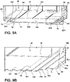
FIGS. 9A and 9B are cross-sectional and detail views of an interior of the vacuum insulated structure of the refrigerator. - The components in the figures are not necessarily to scale, emphasis instead being placed upon illustrating the principles described herein.
- The present illustrated embodiments reside primarily in combinations of method steps and apparatus components related to a vacuum insulated structure for a refrigerator. Accordingly, the apparatus components and method steps have been represented, where appropriate, by conventional symbols in the drawings, showing only those specific details that are pertinent to understanding the embodiments of the present disclosure so as not to obscure the disclosure with details that will be readily apparent to those of ordinary skill in the art having the benefit of the description herein. Further, like numerals in the description and drawings represent like elements.
- For purposes of description herein, the terms "upper," "lower," "right," "left," "rear," "front," "vertical," "horizontal," and derivatives thereof shall relate to the disclosure as oriented in
FIG. 1 . Unless stated otherwise, the term "front" shall refer to the surface of the element closer to an intended viewer, and the term "rear" shall refer to the surface of the element further from the intended viewer. However, it is to be understood that the disclosure may assume various alternative orientations, except where expressly specified to the contrary. It is also to be understood that the specific devices and processes illustrated in the attached drawings, and described in the following specification are simply exemplary embodiments of the inventive concepts defined in the appended claims. Hence, specific dimensions and other physical characteristics relating to the embodiments disclosed herein are not to be considered as limiting, unless the claims expressly state otherwise. - The terms "including," "comprises," "comprising," or any other variation thereof, are intended to cover a non-exclusive inclusion, such that a process, method, article, or apparatus that comprises a list of elements does not include only those elements but may include other elements not expressly listed or inherent to such process, method, article, or apparatus. An element proceeded by "comprises a ... " does not, without more constraints, preclude the existence of additional identical elements in the process, method, article, or apparatus that comprises the element. As used herein, the term "about" may be used to modify a dimension or other numeric value to indicate an approximate value that may, for example, encompass various manufacturing tolerance ranges and/or errors in measurement techniques and associated tools or devices, as are generally known in the art. Additionally or alternatively, the term "about" may indicate that the associated measurement of value may vary from that listed by +/- 10%.
- Referring to
FIGS. 1A-9B ,reference numeral 12 generally designates a vacuum insulated structure. The vacuum insulatedstructure 12 includes a plurality of cover members, each of a stamped unitary sheet. In this respect, the cover members can comprise the portions of theouter wrapper 18, as well as theliners FIGS. 1A and1B . In particular, as shown inFIGS. 4 and6 , theouter liner 18 can comprise separate cover members in the form of a central unitarystructural member 52 that includes thetop wrapper wall 54, therear wrapper wall 62, and thebottom wrapper wall 56, as well as two side members that entirely comprise eachwrapper side wall cover members 52 and each of theside members perimeter portion deformation control member perimeter portion structure 12 also includes athermal bridge 22 interconnecting at least portions of the cover members (i.e., the central unitarystructural member 52, theside cover members upper liner 30, and thelower liner 32 at theperimeter portions 66,68 (as well as the perimeter portions 31,33 of theupper liner 30 andlower liner 32, respectively) to define aninsulating cavity 24 therebetween. Theinsulating cavity 24 is a sealed cavity having a vacuum drawn therefrom, and thedeformation control members cover members deformation control member path 88 for air flow out of the sealedcavity 24 during a vacuum draw process. In this manner, the present vacuum insulatedstructure 12 provides anouter wrapper 18 configured to provide a predictable or "controlled" vacuum bow deflection during vacuum draw by way of thedeformation control members deformation control members cover members deformation control members structure 12 or can accommodate additional elements or features to promote air draw, as discussed further below. - Referring now to
FIG. 1A , arefrigerator 10 is shown having a vacuum insulatedcabinet structure 12. The vacuum insulatedcabinet structure 12 includes one or morefront openings doors doors front opening 14A. As further found in the illustrated example,door 16C is in the form of a sliding drawer which horizontally slides between open and closed positions for selectively providing access to the lowerfront opening 14B of theinsulated cabinet structure 12. - As further shown in
FIG. 1A , the vacuum insulatedcabinet structure 12 includes anexterior wrapper 18 and upper andlower liners FIG. 1A , the upper andlower liners lower liners exterior wrapper 18 via athermal bridge 22. Thethermal bridge 22 is best shown inFIG. 1B . As further shown inFIG. 1A , theexterior wrapper 18 is spaced-apart from the upper andlower liners cavity 24 therebetween. The insulatingcavity 24 is contemplated to be a sealed cavity that may comprise a vacuum core material such as a silica powder or other suitable loose filler material that is inserted (e.g., blown) into the insulatingcavity 24 after theexterior wrapper 18, upper andlower liners thermal bridge 22 have been coupled together. - Referring now to
FIG. 1B , the vacuum insulatedcabinet structure 12 is shown in an exploded view. Thethermal bridge 22 of the vacuum insulatedcabinet structure 12 includes first andsecond side members lower openings lower liners thermal bridge 22 further includes amullion portion 28 disposed between the upper andlower openings second side members upper liner 20A is shown having atop wall 30, abottom wall 32, opposedside walls refrigerator compartment 40. Similarly, thelower liner 20B includes atop wall 42, abottom wall 44, interconnectingsidewalls rear wall 49 which all cooperate to define afreezer compartment 50. Therear wall 49 is shown having a stepped configuration to define aspacing 52 which may be used to house various cooling components for cooling both therefrigerator compartment 40 and thefreezer compartment 50. The upper andlower liners refrigerator compartment 40 and thefreezer compartment 50. - As further shown in
FIG. 1B , theexterior wrapper 18 includes atop wall 54, abottom wall 56, opposed sidewalls 58, 60 and a rear wall 62 (collectively referred to herein as sidewalls) which together cooperate to define a receivingcavity 64. Theexterior wrapper 18 may be comprised of a sheet metal material that is folded and/or welded to define the parameters of the receivingcavity 64 such that thewrapper 18 is generally of a unitary structure. In assembly, the upper andlower liners cavity 64 of theexterior wrapper 18, such that the exterior surfaces of the upper andlower liners exterior wrapper 18 to define the insulatingcavity 24 disposed therebetween as shown inFIG. 1A . The insulatingcavity 24 may directly receive an insulating material and have a vacuum drawn directly from the insulatingcavity 24 to provide a vacuum insulatedcabinet structure 12. In this way, the vacuum insulatedcabinet structure 12 may include an overall thinner profile to maximize the amount of space available for therefrigerator compartment 40 and thefreezer compartment 50 in assembly. - Referring now to
FIG. 2A , aschematic assembly 70 is used to describe a deformation effect of a vacuum drawing procedure. Theassembly 70 includes first andsecond cover members second cover members assembly 70 includes acavity 80 defined by the first andsecond cover members cavity 80 may be filled with a particulate material, such as a compressed cake of activated carbon black or silica gel, or a mixture of the two. These fillers are designed to fill thecavity 80 and are placed therein before a vacuum is drawn on theassembly 70. The filler is indicated byreference numeral 81 and is best shown inFIG. 3A . - Referring now to
FIG. 2B , theschematic assembly 70 has had a vacuum drawn on thecavity 80, such that thecavity 80 now defines an evacuatedcavity 80. By drawing the vacuum on theschematic assembly 70, the first andsecond cover members outer surface 72A offirst cover member 72 as shown inFIG. 2B . The deformation of theschematic assembly 70 shown inFIG. 2B is best depicted inFIG. 3B . - Referring now to
FIG. 3A , the cross-sectional view of theschematic assembly 70 shown inFIG. 2A is depicted, wherein theouter surface 72A of thefirst cover member 72 and anouter surface 74A of thesecond cover member 74 are shown in substantially planar configurations betweenside members FIG. 3A is an ideal configuration for a vacuum insulated structure after a vacuum has been drawn on theschematic assembly 70. However, as noted above, when a vacuum is drawn on theschematic assembly 70 ofFIGS. 2A and3A , a deformedschematic assembly 70, as shown inFIGS. 2B and3B , is often the result. With specific reference toFIG. 3B , theouter surfaces second cover members specific indent deformations 84A-84D which draw the first andsecond cover members cavity 80. The pressure within the evacuated cavity ofassembly 70 is contemplated to be less than 10 mbar as compared to an atmospheric pressure of 1 atm or 1013.25 mbar. - In an effort to avoid the vacuum deformation bow shown in the
schematic assembly 70 ofFIGS. 2A-3B , the present concept includes a vacuum insulated structure having an area configured for controlled deformation. Referring toFIGS. 4-9B , the above-mentioned plurality of cover members are shown, each in the form of a stamped unitary sheet. Theouter liner 18 is shown as comprising cover members in the form of a central unitarystructural member 52 that includes thetop wrapper wall 54, therear wrapper wall 62, and thebottom wrapper wall 56, as well as two side members that entirely comprise eachwrapper side wall FIGS. 4 and5 , both the central unitarystructural member 52 and each of theside members perimeter portion deformation control member perimeter portion - The vacuum
insulated structure 12 also includes thethermal bridge 22, such as depicted inFIGS. 1A and1B , interconnecting the first cover members (i.e., the central unitarystructural member 52, theside cover members upper liner 30, and thelower liner 32 at theperimeter portions 66,68 (as well as the perimeter portions 31,33 of theupper liner 30 andlower liner 32, respectively) to define the insulatingcavity 24 therebetween. Thedeformation control members cover members deformation control member path 88 for air flow out of the sealedcavity 24 during a vacuum draw process. - As mentioned above, and as shown in
FIG. 6 , the above-mentioned cover members include unitary sheets comprising thesides wrapper 18, as well as the central unitarystructural member 52. Theside cover members outer perimeters 68 to corresponding portions of theperimeter 66 of thecentral member 52. As shown, the portions of theperimeters 68 of theside members perimeter 66 of thecentral member 52 definerespective edge portions perimeter 68 that align with thetop wall 54,rear wall 62, andbottom wall 56 of thewrapper 18, as defined on thecentral member 52. In this manner, remaining front-top 66a, front-bottom 66b, and front 68d edges of thecentral member 52 andside members thermal bridge 22 to enclose thecavity 24 by way of additional coupling with the remaining cover members in the form of theupper liner 30 and lower liner 32 (with other configurations possible, depending on the particular configuration of refrigerator 10). In such a configuration, it can be appreciated that thecentral member 52, in particular, may define multiple first planar levels P1, as the entireouter perimeter 66 thereof follows the shape of thecentral member 52 around thevarious walls wrapper 18 defined thereon, the various perimeter planar levels designated as P1, and corresponding axial A and radial R directions, being established with respect to the portions of theperimeter 66 that correspond with the portions thereof surrounding thesubject walls wrapper 18, theside cover members central unit 52, and the resultingouter wrapper 18 to give the wrapper 18 a unitary, impermeable configuration. - Prior to sealing of
cavity 24, which may be achieved by sealingly couplingthermal bridge 22 over theliners outer wrapper 18, thecavity 18 can be filled with an insulating filler material in the form of various powders or granular particles that can generally fill the space that comprises thecavity 24. In particular, the insulating filler material can be open celled foam or a microporous filler material which may optionally include particulate reflectors or opacifiers, such as aluminum, flake or carbon black, to reduce transmission of radiation energy through the vacuum insulatedstructure 12. Thecavity 100 may also be filled with an insulating material in the form of a powder comprised of fumed silica, glass beads, processed rice husks, or any combination thereof. The insulating material is contemplated to have a conducting coefficient or thermal conductivity of at least 5 mW/m·K, or lower, to ensure that the insulating properties of the vacuum insulatedstructure 12 are sound. - The assembled vacuum insulated
structure 12 is then subjected to an evacuation process, wherein thecavity 24, accessed viaport 86 to draw a vacuum from thecavity 24, thereby providing a low pressure environment within thecavity 24. The low pressure environment of thecavity 24 may include a reduced internal pressure of less than 10 mbar, but may include other pressure settings conditioned on a filler material used in the vacuum insulatedstructure 12, and also conditioned on the desired insulative value of the vacuum insulatedstructure 12. As discussed above, the withdrawal of air fromcavity 24 and the resulting low pressure environment ofcavity 24 causes inwardly-directed forces to be applied to thevarious walls wrapper 18 and thewalls liners walls wrapper 18 are configured to direct a majority of the deformative effects of the inwardly-directed forces to within certain areas and to limit the overall deflection to within a specified overall distance. In one such aspect, thecentral member 52 and theside members deformation control member 82 in the form of one or more stepped areas thereof that are each generally defined by a stepped segment 90 that extends to an outward planar level P2 from toward the perimeter planar level P1. In this manner, each of thecentral member 52 and theside members inner surface portion 92 framed by the steppedareas 82, with theinner surface portions 92 being positioned along the outward planar level P2. - As shown in the detail view of
FIG. 5 , the steppedareas 82 can include multiple steps between the perimeter planar level P1 and the outward planar level P2. In particular, the steppedareas 82 can include a first steppedsegment 90a extending from the perimeter planar level P1 toward the outward planar level P2 and a second steppedsegment 90b extending from a position generally aligned with an outward-most portion of the first steppedsegment 90a and to the outward planar level P2. The steppedsegments intermediate face segment 94 that extends generally parallel to the planar levels P1 and P2. In this manner, the orientation of the steppedsegments cover members segments face segment 94 can allow the steppedarea 82 to collapse inwardly under the inwardly-directed forces generated by the vacuum draw. This can occur by inward flexing of theface segment 94 such that the second steppedsegment 90b can move inwardly in a direction generally parallel with the first steppedsegment 90a in a generally fan-fold type manner. Additional deformation of thecover member perimeter portion segment 90a or within theinner face 92 in an area immediately adjacent the second steppedsegment 90b. In general, the appearance of deformations in such areas may be less noticeable to an observer by being visually obscured by the adjacent visual features of the steppedarea 82. As also shown inFIGS. 4 and5 , thecentral member 52 may include an additional steppedarea 96 that extends to an additional planar level P3 disposed outward of the outer planar level P2. Such additional steppedarea 96 can wrap around a portion ofcentral member 52 that includes portions of both thetop wall 54 and therear wall 62 and may provide additional reinforcement ofcentral member 52 and/or additional air flow during vacuum deformation in a manner discussed further below. - As also mentioned above, a further deformation control member is configured as
rib 84 that can be positioned along either or both ofcentral member 52 andside members various ribs 84 are positioned along theinner surface portions 92 of thevarious cover members areas 82 and extend from the outward planar level P2 to an additional planar level P3 positioned further outward from the outward planar level P2 in the axial direction A. In one aspect, theribs 84 can provide structural reinforcement for theinner surface portions 92 such that deflection therealong from the above-described vacuum draw. As can be appreciated, this effect further limits the overall deformation of thecover members areas 82. Additionally, the presence of theribs 84, particularly in the illustrated grid patterns, described further below, further serves to visually obscure any deformation that may occur within theinner surface portions 92. In general, the configuration ofdeformation control members cover members - As shown, the various depicted
ribs 84 define an openinterior portion 98 that extend outwardly from aninterior surface 100 of therespective cover member ribs 84 each extend along arespective axis 85. As shown, theside members more ribs 84a that extend at an oblique angle Ω of between 10° and 40° with respect to the adjacentfront edge 68a of theside member such side member oblique ribs 84a that, in the illustrated example extend at about 30° with respect to thefront edge 68a, but may include moresuch ribs 84a, depending on the particular configuration of therefrigerator 10. Associated with each suchoblique rib 84a are a group ofsecondary ribs 84b, theaxes 85 of which extend in a direction oriented between 80° and 100° relative to the direction of theoblique ribs 84a. In the illustrated example, thesecondary ribs 84b are oriented at a 90° angle relative to theoblique ribs 84a and intersect a respective one of theoblique ribs 84a at various points therealong. In this manner, the respective openinterior portions 98 of thesecondary ribs 84b are connected and in communication with the open interior portion of the correspondingoblique rib 84a such that the open interior portions, individually and collectively, define further respective portions of thepath 88 for air flow out of the sealedcavity 24 during the vacuum draw process. Additional secondary ribs 84c may be separate from theoblique ribs 84a to maintain visual consistency along theinner surface portion 92. Theribs 84 within thecentral member 52 may includehorizontal ribs 84d andvertical ribs 84e that also define openinterior portions 98 that intersect to define an additional network of interconnected portions of theair flow path 88. - As discussed above, the sealed
cavity 24 may be filled with an insulating material prior to sealing and vacuum draw. Notably, during vacuum draw, the inward deformation of portions of the various cover members, including ofcentral member 52 andside members liners ribs open interiors 98 thereof is compressed to a lesser extent during vacuum draw such that the corresponding portions of theair flow path 88 remain relatively unobstructed such that air may, at least in part, be drawn from adjacent portions of the filler material within thecavity 24 into the openinterior portions 98 to provide a less obstructedpath 88 for air flow than may otherwise be realized. - Additionally, as shown in
FIGS. 9A and 9B , an interior area 102 ofcavity 24 defined within the stepped areas 82 (i.e. along the interior of inner surface portion 92) can receive amesh material layer 104 therein. In one aspect, themesh material layer 104 can be generally rigid, so as to resist compression during the vacuum draw process, and porous. Due to its rigidity, themesh material layer 104 can maintain its porosity during the vacuum draw process and can maintain the insulating material out of the interior area 102 during the vacuum draw process such that an additional route for air flow out ofcavity 24 is provided. As shown, themesh material layer 104 can overlie theport 86 such that air drawn therethrough, in particular, has a relatively unobstructed path to theport 86. Themesh material layer 104 can be held to the interior area 102 with one or more strips offilter paper 106 that may be adhered to a portion of themesh material layer 104 and an adjacent portion of theinterior surface 100 of thecentral member 52, including within the steppedarea 82. Similar to the mesh material layer, thefilter paper 106 may be air permeable but can have a small enough void or pore size to not be permeated by the adjacent insulating material. - The invention disclosed herein is further summarized in the following paragraphs and is further characterized by combinations of any and all of the various aspects described therein.
- According to another aspect of the present disclosure, a vacuum insulated structure includes a first cover member of a stamped unitary sheet defining a perimeter portion positioned at a first planar level and a deformation control member formed in the unitary sheet extending to a second planar level spaced axially outward and disposed radially inward of the perimeter portion. The vacuum insulated structure also includes a second cover member and a thermal bridge interconnecting the first cover member and the second cover member at the perimeter portions thereof to define an insulating cavity therebetween. The insulating cavity is a sealed cavity having a vacuum drawn therefrom, and the first deformation control member is configured to reduce deformation of the first cover member in at least an area adjacent the deformation control member and to define a portion of a path for air flow out of the sealed cavity during a vacuum draw process.
- The deformation control member is configured as a first rib defining an open interior portion extending axially outward of an inner surface of the first cover member. The rib extends along an axis disposed at an angle of between 15° and 40° with respect to an edge of the cover member comprising the perimeter portion.
- The axis of the first rib is disposed at about 30° with respect to the edge.
- The first rib is one of a plurality of ribs comprising a first group of ribs extending in a first direction and a second group of ribs extending in a second direction oriented between 30° and 50° relative to the first direction.
- Each of the ribs define respective open interior portions extending axially outward of an inner surface of the first cover member portion to define further respective portions of the path for air flow out of the sealed cavity during the vacuum draw process.
- The vacuum insulated structure further includes an insulating material disposed within the insulating cavity. The path for air flow out of the sealed cavity during the vacuum draw process facilitates removal of air from within the insulating material.
- The first deformation control member is a stepped area defined by a stepped segment of the first cover member extending to the second planar level from toward the first planar level. The vacuum insulating structure further includes a mesh material layer received in the stepped area and configured to maintain the insulating material out of the portion of the air flow path defined within the stepped area.
- The vacuum insulated structure further includes an air permeable member adhered between a portion of the mesh material layer and a portion of an interior surface of the first cover member.
- According to yet another aspect, a refrigerator includes a first cover member of a stamped unitary sheet defining a perimeter portion positioned at a first planar level and a deformation control member formed in the unitary sheet extending to a second planar level spaced axially outward and disposed radially inward of the perimeter portion. The deformation control member is configured as a first rib defining an open interior portion extending axially outward of an inner surface of the first cover member. The rib extends along an axis disposed at an angle of between 15° and 40° with respect to an edge of the cover member comprising the perimeter portion. The refrigerator further includes a second cover member and a thermal bridge interconnecting the first cover member and the second cover member at the perimeter portions thereof to define an insulating cavity therebetween. The insulating cavity is a sealed cavity having a vacuum drawn therefrom, and the first deformation control member is configured to reduce deformation of the first cover member in at least an area adjacent the rib.
- The open interior portion of the first rib defines a portion of a path for air flow out of the sealed cavity during a vacuum draw process.
- The first rib is one of a plurality of ribs comprising a first group of ribs extending in a first direction and a second group of ribs extending in a second direction oriented between 30° and 50° relative to the first direction. Each of the plurality of ribs define respective, interconnected open interior portions to further define the path for air flow.
- The axis of the first rib is disposed at about 30° with respect to the edge
- The first cover member is a side wall of an outer wrapper of the refrigerator, the second cover member is an inner liner disposed inward of the outer wrapper, and the thermal bridge surrounds an opening to an inner cavity of the refrigerator defined by the inner liner. The refrigerator further includes at least one door operably closing the opening.
- The first cover member is a side wall of an outer wrapper of the refrigerator, and the second cover member is a unitary structural portion of the outer wrapper that defines a rear wall, a top wall, and a bottom wall of the outer wrapper. The second cover member is coupled to the first cover member along bottom, rear, and side edges of the perimeter portion. The thermal bridge interconnects the first cover member and the second cover member between a front edge of the first cover member and both a top-front edge and a bottom-front edge of the second cover member.
- The second cover member defines a stepped area defined by a stepped segment of the second cover member within at least one of the rear wall and the top wall.
- According to yet another aspect, a refrigerator includes a first cover member of a stamped unitary sheet defining a perimeter portion positioned at a first planar level and a deformation control member formed in the unitary sheet extending to a second planar level spaced axially outward and disposed radially inward of the perimeter portion. The deformation control member is configured as a stepped area defined by a stepped segment of the first cover member extending to the second planar level from toward the first planar level. The refrigerator further includes a second cover member, a thermal bridge interconnecting the first cover member and the second cover member at the perimeter portions thereof to define an insulating cavity therebetween, an insulating material disposed within the insulating cavity, and a mesh material layer received in the stepped area. The insulating cavity is a sealed cavity having a vacuum drawn therefrom, and the first deformation control member is configured to reduce deformation of the first cover member in at least an area adjacent the deformation control member and to define a portion of a path for air flow out of the sealed cavity during a vacuum draw process. The mesh material layer is configured to maintain the insulating material out of the portion of the air flow path defined within the stepped area.
- The refrigerator further includes an air permeable member adhered between a portion of the mesh material layer and a portion of an interior surface of the first cover member.
- The stepped segment of the deformation control member is a first stepped segment. The stepped area is further defined by a second stepped segment extending from the first planar level toward the second planar level, and the second stepped segment is disposed radially inward of the first stepped segment.
- The first cover member is a unitary structural portion of an outer wrapper of the refrigerator that defines a rear wall, a top wall, and a bottom wall of the outer wrapper. The stepped area is a first stepped area, and the first cover member defines a second stepped area within the top wall of the unitary structural portion. The second cover member is a side wall of an outer wrapper of the refrigerator and is coupled to the first cover member along bottom, rear, and side edges of the perimeter portion. The thermal bridge interconnects the first cover member and the second cover member between a front edge of the first cover member and both a top-front edge and a bottom-front edge of the second cover member.
- The second cover member includes a first rib defining an open interior portion extending axially outward of an inner surface of the first cover member. The rib extends along an axis disposed at an angle of between 15° and 40° with respect to an edge of the cover member comprising the perimeter portion.
Claims (15)
- A vacuum insulated structure (12), comprising:a first cover member (72) of a stamped unitary sheet defining a perimeter portion (66, 68) positioned at a first planar level (P1) and a deformation control member (82, 84) formed in the unitary sheet extending to a second planar level (P2) spaced axially outward and disposed radially inward of the perimeter portion (66, 68);a second cover member (74); anda thermal bridge (22) interconnecting the first cover member (72) and the second cover member (74) at the perimeter portions (66, 68) thereof to define an insulating cavity (24) therebetween, wherein the insulating cavity (24) is a sealed cavity (24) having a vacuum drawn therefrom, and further wherein the first deformation control member (82) is configured as a first rib defining an open interior portion (98) extending axially outward of an inner surface (100) of the first cover member (72), thereby reducing deformation of the first cover member (72) in at least an area adjacent the deformation control member (82) and to define a portion of a path for air flow out of the sealed cavity (24) during a vacuum draw process.
- The vacuum insulated structure (12) of claim 1, wherein the deformation control member (82, 84) configured as a first rib extends along an axis disposed at an angle of between 15° and 40° with respect to an edge (68a, 68b, 68c) of the cover member (72, 74) comprising the perimeter portion (66, 68).
- The vacuum insulated structure (12) of claim 2, wherein the axis of the first rib is disposed at about 30° with respect to the edge (68a, 68b, 68c).
- The vacuum insulated structure (12) of claim 3, wherein the first rib is one of a plurality of ribs comprising a first group of ribs extending in a first direction and a second group of ribs extending in a second direction oriented between 80° and 100° relative to the first direction.
- The vacuum insulated structure (12) of claim 4, wherein each of the plurality of ribs defines an open interior portion extending axially outward of an interior surface (100) of the first cover member (72) such that the plurality of ribs define further respective portions of the path for air flow out of the sealed cavity (24) during the vacuum draw process.
- The vacuum insulated structure (12) of any of the preceding claims, further including an insulating material disposed within the insulating cavity (24), wherein:
the path for air flow out of the sealed cavity (24) during the vacuum draw process facilitates removal of air from within the insulating material. - The vacuum insulated structure (12) of claim 6, wherein the first deformation control member (82) is a stepped area defined by a stepped segment (90) of the first cover member (72) extending to the second planar level (P2) from toward the first planar level (P1), the vacuum insulating structure (12) further including:
a mesh material layer (104) received in the stepped area (82) and configured to maintain the insulating material out of the portion of the air flow path defined within the stepped area (82). - The vacuum insulated structure (12) of claim 7, further including an air permeable member adhered between a portion of the mesh material layer (104) and a portion of an interior surface (100) of the first cover member (72).
- The vacuum insulated structure of claim 1, wherein the stepped segment of the deformation control member is a first stepped segment, the stepped area being further defined by a second stepped segment extending from the first planar level toward the second planar level, the second stepped segment being disposed radially inward of the first stepped segment.
- A refrigerator (10), comprising the vacuum insulated structure of any of the preceding claims.
- The refrigerator (10) of claim 10, wherein:the first cover member (72) is a side wall (34, 36) of an outer wrapper (18) of the refrigerator (10);the second cover member (74) is an inner liner (20) disposed inward of the outer wrapper (18); andthe thermal bridge (22) surrounds an opening (14) to an inner cavity (24) of the refrigerator (10) defined by the inner liner (20), the refrigerator (10) further including at least one door (16) operably closing the opening (14).
- The refrigerator (10) of claim 10, wherein:the first cover member (72) is a side wall (34, 36) of an outer wrapper (18) of the refrigerator (10);the second cover member (74) is a unitary structural portion of the outer wrapper (18) that defines a rear wall (38), a top wall (30), and a bottom wall (32) of the outer wrapper (18), the second cover member (74) being coupled to the first cover member (72) along bottom, rear, and side edges (68a, 68b, 68c) of the perimeter portion (66, 68); andthe thermal bridge (22) interconnects the first cover member (72) and the second cover member (74) between a front edge (68a) of the first cover member (72) and both a top-front edge (66a) and a bottom-front edge (66b) of the second cover member (74).
- The refrigerator (10) of claim 12, wherein the second cover member (74) defines a stepped area (82) defined by a stepped segment (90) of the second cover member (74) within at least one of the rear wall (38) and the top wall (30).
- The refrigerator (10) of claim 10, wherein:the first cover member (72) is a unitary structural portion (52) of an outer wrapper (18) of the refrigerator (10) that defines a rear wall (38), a top wall (30), and a bottom wall (32) of the outer wrapper (18), the stepped area (82) being a first stepped area, and the first cover member (72) defining a second stepped area within the top wall (30) of the unitary structural portion (52);the second cover member (74) is a side wall (58, 60) of the outer wrapper (18) of the refrigerator (10), the second cover member (74) being coupled to the first cover member (72) along bottom, rear, and side edges (68a, 68b, 68c) of the perimeter portion (66, 68); andthe thermal bridge (22) interconnects the first cover member (72) and the second cover member (74) between a front edge (68a) of the first cover member (72) and both a top-front edge (66a) and a bottom-front edge (66b) of the second cover member (74).
- The refrigerator (10) of claim 14, wherein the second cover member (74) includes a first rib defining an open interior portion (98) extending axially outward of an inner surface (92) of the first cover member (72), the first rib extending along an axis disposed at an angle of between 15° and 40° with respect to an edge (68a, 68b, 68c) of the cover member (72, 74) comprising the perimeter portion (66, 68).
Applications Claiming Priority (1)
| Application Number | Priority Date | Filing Date | Title |
|---|---|---|---|
| US17/146,546 US11448355B2 (en) | 2021-01-12 | 2021-01-12 | Vacuum insulated refrigerator structure with feature for controlling deformation and improved air withdrawal |
Publications (2)
| Publication Number | Publication Date |
|---|---|
| EP4027088A1 true EP4027088A1 (en) | 2022-07-13 |
| EP4027088B1 EP4027088B1 (en) | 2023-09-20 |
Family
ID=79317106
Family Applications (1)
| Application Number | Title | Priority Date | Filing Date |
|---|---|---|---|
| EP22150821.1A Active EP4027088B1 (en) | 2021-01-12 | 2022-01-10 | Vacuum insulated refrigerator structure with feature for controlling deformation and improved air withdrawal |
Country Status (3)
| Country | Link |
|---|---|
| US (2) | US11448355B2 (en) |
| EP (1) | EP4027088B1 (en) |
| CN (1) | CN114763959A (en) |
Families Citing this family (6)
| Publication number | Priority date | Publication date | Assignee | Title |
|---|---|---|---|---|
| WO2018022009A1 (en) * | 2016-07-26 | 2018-02-01 | Whirlpool Corporation | Thermal bridgebreaker and seal features in a thin-walled vacuum insulated structure |
| JP7249782B2 (en) * | 2019-01-07 | 2023-03-31 | 東芝ライフスタイル株式会社 | refrigerator |
| DE102019213447A1 (en) * | 2019-09-04 | 2021-03-04 | BSH Hausgeräte GmbH | Refrigeration device |
| US11448355B2 (en) * | 2021-01-12 | 2022-09-20 | Whirlpool Corporation | Vacuum insulated refrigerator structure with feature for controlling deformation and improved air withdrawal |
| US11709013B2 (en) * | 2021-01-20 | 2023-07-25 | Whirlpool Corporation | Appliance trim breaker |
| US12320577B2 (en) * | 2023-02-21 | 2025-06-03 | Whirlpool Corporation | Refrigerator cabinet with a trim breaker and vacuum insulated panel associated with the trim breaker |
Citations (4)
| Publication number | Priority date | Publication date | Assignee | Title |
|---|---|---|---|---|
| GB730146A (en) * | 1952-07-30 | 1955-05-18 | Gen Electric | Improvements in and relating to insulating structures |
| EP1335171A1 (en) * | 2002-02-07 | 2003-08-13 | Whirlpool Corporation | Domestic refrigerator and procedure for producing the same |
| US20190285336A1 (en) * | 2017-01-18 | 2019-09-19 | Whirlpool Corporation | Use of rigid or permeable conduits for achieving faster vacuum evacuation time in vacuum insulated structures |
| US20200103067A1 (en) * | 2018-09-28 | 2020-04-02 | Whirlpool Corporation | Channel system for a vacuum insulated structure |
Family Cites Families (31)
| Publication number | Priority date | Publication date | Assignee | Title |
|---|---|---|---|---|
| GB760338A (en) | 1952-10-28 | 1956-10-31 | Gen Electric | Improvements in and relating to insulating structures |
| US4536990A (en) | 1982-05-17 | 1985-08-27 | Sundstrand Corporation | Torsionally stiff lightweight refrigerator/freezer door |
| US6230500B1 (en) | 1999-09-29 | 2001-05-15 | Mve, Inc. | Cryogenic freezer |
| KR100541061B1 (en) | 2002-12-27 | 2006-01-11 | 제일모직주식회사 | Multilayer Sheet for Refrigerator Interior with Metal Texture |
| JP4580843B2 (en) | 2005-08-24 | 2010-11-17 | 日立アプライアンス株式会社 | Vacuum heat insulating material and refrigerator using the same |
| KR100725834B1 (en) * | 2006-03-31 | 2007-06-08 | 삼성광주전자 주식회사 | Manufacturing method of refrigerator and its inner case |
| DE102007029184A1 (en) | 2007-06-25 | 2009-01-08 | BSH Bosch und Siemens Hausgeräte GmbH | Heat-insulating wall for a refrigeration appliance |
| KR101227516B1 (en) * | 2010-10-28 | 2013-01-31 | 엘지전자 주식회사 | A refrigerator comprising a vacuum space |
| KR101898487B1 (en) | 2010-10-28 | 2018-10-04 | 엘지전자 주식회사 | A refrigerator comprising a vaccum space |
| KR101147779B1 (en) * | 2010-10-28 | 2012-05-25 | 엘지전자 주식회사 | A refrigerator comprising a vaccum space |
| JP6005341B2 (en) | 2011-06-13 | 2016-10-12 | 東芝ライフスタイル株式会社 | refrigerator |
| JP5689387B2 (en) | 2011-08-30 | 2015-03-25 | 日立アプライアンス株式会社 | Refrigerator and manufacturing method thereof |
| JP2013088036A (en) | 2011-10-19 | 2013-05-13 | Hitachi Appliances Inc | Thermal insulation box, refrigerator, and storage type water heater |
| US8986483B2 (en) | 2012-04-02 | 2015-03-24 | Whirlpool Corporation | Method of making a folded vacuum insulated structure |
| EP2765375B1 (en) | 2013-02-06 | 2018-09-12 | Samsung Electronics Co., Ltd | Vacuum insulation material, insulation case unit, and refrigerator |
| US20140360603A1 (en) | 2013-06-10 | 2014-12-11 | The Cola-Cola Company | Systems and methods for a vacuum insulated panel |
| US9574819B2 (en) | 2014-01-07 | 2017-02-21 | Samsung Electronics Co., Ltd. | Refrigerator |
| US9498072B2 (en) | 2014-02-11 | 2016-11-22 | Anthony, Inc. | Display case door assembly with tempered glass vacuum panel |
| US20160258671A1 (en) | 2015-03-02 | 2016-09-08 | Whirlpool Corporation | Gas barrier for vacuum insulation |
| EP3270032A4 (en) | 2015-03-10 | 2018-10-17 | Toshiba Lifestyle Products & Services Corporation | Vacuum insulated panel, core material, and refrigerator |
| US10018406B2 (en) | 2015-12-28 | 2018-07-10 | Whirlpool Corporation | Multi-layer gas barrier materials for vacuum insulated structure |
| US11247369B2 (en) | 2015-12-30 | 2022-02-15 | Whirlpool Corporation | Method of fabricating 3D vacuum insulated refrigerator structure having core material |
| EP3519746B1 (en) | 2016-10-03 | 2022-10-26 | Whirlpool Corporation | Encapsulation system for a thermal bridge breaker-to-metal liner |
| EP3523584B1 (en) * | 2016-10-04 | 2022-08-24 | Whirlpool Corporation | Structural formations incorporated within a vacuum insulated structure |
| US10697698B2 (en) * | 2016-12-23 | 2020-06-30 | Whirlpool Corporation | Vacuum insulated panel for counteracting vacuum bow induced deformations |
| EP3571453B1 (en) | 2017-01-18 | 2023-05-24 | Whirlpool Corporation | Use of edge located channels for achieving faster vacuum evacuation time in vacuum insulated structures |
| US11300354B2 (en) * | 2017-10-05 | 2022-04-12 | Whirlpool Corporation | Filling ports for insulated structures incorporated within an appliance |
| KR102511095B1 (en) * | 2017-12-13 | 2023-03-16 | 엘지전자 주식회사 | Vacuum adiabatic body and refrigerator |
| WO2020157825A1 (en) | 2019-01-29 | 2020-08-06 | 三菱電機株式会社 | Refrigerator |
| US10697696B1 (en) * | 2019-02-25 | 2020-06-30 | Whirlpool Corporation | Vacuum insulated structure with internal airway system |
| US11448355B2 (en) * | 2021-01-12 | 2022-09-20 | Whirlpool Corporation | Vacuum insulated refrigerator structure with feature for controlling deformation and improved air withdrawal |
-
2021
- 2021-01-12 US US17/146,546 patent/US11448355B2/en active Active
- 2021-12-30 CN CN202111657939.1A patent/CN114763959A/en active Pending
-
2022
- 2022-01-10 EP EP22150821.1A patent/EP4027088B1/en active Active
- 2022-08-09 US US17/883,717 patent/US11708935B2/en active Active
Patent Citations (4)
| Publication number | Priority date | Publication date | Assignee | Title |
|---|---|---|---|---|
| GB730146A (en) * | 1952-07-30 | 1955-05-18 | Gen Electric | Improvements in and relating to insulating structures |
| EP1335171A1 (en) * | 2002-02-07 | 2003-08-13 | Whirlpool Corporation | Domestic refrigerator and procedure for producing the same |
| US20190285336A1 (en) * | 2017-01-18 | 2019-09-19 | Whirlpool Corporation | Use of rigid or permeable conduits for achieving faster vacuum evacuation time in vacuum insulated structures |
| US20200103067A1 (en) * | 2018-09-28 | 2020-04-02 | Whirlpool Corporation | Channel system for a vacuum insulated structure |
Also Published As
| Publication number | Publication date |
|---|---|
| US20220381390A1 (en) | 2022-12-01 |
| US11708935B2 (en) | 2023-07-25 |
| US20220221099A1 (en) | 2022-07-14 |
| CN114763959A (en) | 2022-07-19 |
| EP4027088B1 (en) | 2023-09-20 |
| US11448355B2 (en) | 2022-09-20 |
Similar Documents
| Publication | Publication Date | Title |
|---|---|---|
| EP4027088B1 (en) | Vacuum insulated refrigerator structure with feature for controlling deformation and improved air withdrawal | |
| US9071907B2 (en) | Vacuum insulated structure tubular cabinet construction | |
| EP3394530B1 (en) | Vacuum insulated refrigerator structure, and method of routing utility lines therein | |
| US11480385B2 (en) | Vacuum insulated panel for counteracting vacuum bow induced deformations | |
| EP2462393B1 (en) | Vacuum insulation member and refrigerator having a vacuum insulation member | |
| EP4023978B1 (en) | Vacuum insulated structure and refrigerator | |
| US10914505B2 (en) | Vacuum insulated door construction | |
| US11752669B2 (en) | Method of fabricating 3D vacuum insulated refrigerator structure having core material | |
| EP3851778A1 (en) | A cabinet of an appliance comprising a reinforcing assembly | |
| US12474012B2 (en) | Collapsible pattern | |
| KR102037044B1 (en) | Insulation-box and its manufacturing method | |
| US20190264859A1 (en) | Vacuum insulated structures having internal chamber structures | |
| CN112577252A (en) | Refrigeration appliance and door body thereof | |
| KR20140102150A (en) | Method for manufacturing insulation box improved insulation performance and insulation box for the same | |
| EP2778580B1 (en) | Vacuum insulated structure tubular cabinet construction | |
| JPH07148752A (en) | Insulation box | |
| JPH07293783A (en) | Insulation material and insulation box body using it | |
| JPH08100978A (en) | Internal condensation prevention structure of the refrigerator | |
| JPH04357399A (en) | Insulating panel | |
| JPH06337092A (en) | Vacuum insulation pack |
Legal Events
| Date | Code | Title | Description |
|---|---|---|---|
| PUAI | Public reference made under article 153(3) epc to a published international application that has entered the european phase |
Free format text: ORIGINAL CODE: 0009012 |
|
| STAA | Information on the status of an ep patent application or granted ep patent |
Free format text: STATUS: THE APPLICATION HAS BEEN PUBLISHED |
|
| AK | Designated contracting states |
Kind code of ref document: A1 Designated state(s): AL AT BE BG CH CY CZ DE DK EE ES FI FR GB GR HR HU IE IS IT LI LT LU LV MC MK MT NL NO PL PT RO RS SE SI SK SM TR |
|
| STAA | Information on the status of an ep patent application or granted ep patent |
Free format text: STATUS: REQUEST FOR EXAMINATION WAS MADE |
|
| 17P | Request for examination filed |
Effective date: 20230105 |
|
| RBV | Designated contracting states (corrected) |
Designated state(s): AL AT BE BG CH CY CZ DE DK EE ES FI FR GB GR HR HU IE IS IT LI LT LU LV MC MK MT NL NO PL PT RO RS SE SI SK SM TR |
|
| RAP3 | Party data changed (applicant data changed or rights of an application transferred) |
Owner name: WHIRLPOOL CORPORATION |
|
| GRAP | Despatch of communication of intention to grant a patent |
Free format text: ORIGINAL CODE: EPIDOSNIGR1 |
|
| STAA | Information on the status of an ep patent application or granted ep patent |
Free format text: STATUS: GRANT OF PATENT IS INTENDED |
|
| INTG | Intention to grant announced |
Effective date: 20230705 |
|
| GRAS | Grant fee paid |
Free format text: ORIGINAL CODE: EPIDOSNIGR3 |
|
| GRAA | (expected) grant |
Free format text: ORIGINAL CODE: 0009210 |
|
| STAA | Information on the status of an ep patent application or granted ep patent |
Free format text: STATUS: THE PATENT HAS BEEN GRANTED |
|
| P01 | Opt-out of the competence of the unified patent court (upc) registered |
Effective date: 20230730 |
|
| AK | Designated contracting states |
Kind code of ref document: B1 Designated state(s): AL AT BE BG CH CY CZ DE DK EE ES FI FR GB GR HR HU IE IS IT LI LT LU LV MC MK MT NL NO PL PT RO RS SE SI SK SM TR |
|
| REG | Reference to a national code |
Ref country code: GB Ref legal event code: FG4D |
|
| REG | Reference to a national code |
Ref country code: CH Ref legal event code: EP |
|
| REG | Reference to a national code |
Ref country code: IE Ref legal event code: FG4D |
|
| REG | Reference to a national code |
Ref country code: DE Ref legal event code: R096 Ref document number: 602022000515 Country of ref document: DE |
|
| REG | Reference to a national code |
Ref country code: LT Ref legal event code: MG9D |
|
| PG25 | Lapsed in a contracting state [announced via postgrant information from national office to epo] |
Ref country code: GR Free format text: LAPSE BECAUSE OF FAILURE TO SUBMIT A TRANSLATION OF THE DESCRIPTION OR TO PAY THE FEE WITHIN THE PRESCRIBED TIME-LIMIT Effective date: 20231221 |
|
| REG | Reference to a national code |
Ref country code: NL Ref legal event code: MP Effective date: 20230920 |
|
| PG25 | Lapsed in a contracting state [announced via postgrant information from national office to epo] |
Ref country code: SE Free format text: LAPSE BECAUSE OF FAILURE TO SUBMIT A TRANSLATION OF THE DESCRIPTION OR TO PAY THE FEE WITHIN THE PRESCRIBED TIME-LIMIT Effective date: 20230920 Ref country code: RS Free format text: LAPSE BECAUSE OF FAILURE TO SUBMIT A TRANSLATION OF THE DESCRIPTION OR TO PAY THE FEE WITHIN THE PRESCRIBED TIME-LIMIT Effective date: 20230920 Ref country code: NO Free format text: LAPSE BECAUSE OF FAILURE TO SUBMIT A TRANSLATION OF THE DESCRIPTION OR TO PAY THE FEE WITHIN THE PRESCRIBED TIME-LIMIT Effective date: 20231220 Ref country code: LV Free format text: LAPSE BECAUSE OF FAILURE TO SUBMIT A TRANSLATION OF THE DESCRIPTION OR TO PAY THE FEE WITHIN THE PRESCRIBED TIME-LIMIT Effective date: 20230920 Ref country code: LT Free format text: LAPSE BECAUSE OF FAILURE TO SUBMIT A TRANSLATION OF THE DESCRIPTION OR TO PAY THE FEE WITHIN THE PRESCRIBED TIME-LIMIT Effective date: 20230920 Ref country code: HR Free format text: LAPSE BECAUSE OF FAILURE TO SUBMIT A TRANSLATION OF THE DESCRIPTION OR TO PAY THE FEE WITHIN THE PRESCRIBED TIME-LIMIT Effective date: 20230920 Ref country code: GR Free format text: LAPSE BECAUSE OF FAILURE TO SUBMIT A TRANSLATION OF THE DESCRIPTION OR TO PAY THE FEE WITHIN THE PRESCRIBED TIME-LIMIT Effective date: 20231221 Ref country code: FI Free format text: LAPSE BECAUSE OF FAILURE TO SUBMIT A TRANSLATION OF THE DESCRIPTION OR TO PAY THE FEE WITHIN THE PRESCRIBED TIME-LIMIT Effective date: 20230920 |
|
| REG | Reference to a national code |
Ref country code: AT Ref legal event code: MK05 Ref document number: 1613677 Country of ref document: AT Kind code of ref document: T Effective date: 20230920 |
|
| PG25 | Lapsed in a contracting state [announced via postgrant information from national office to epo] |
Ref country code: NL Free format text: LAPSE BECAUSE OF FAILURE TO SUBMIT A TRANSLATION OF THE DESCRIPTION OR TO PAY THE FEE WITHIN THE PRESCRIBED TIME-LIMIT Effective date: 20230920 |
|
| PG25 | Lapsed in a contracting state [announced via postgrant information from national office to epo] |
Ref country code: IS Free format text: LAPSE BECAUSE OF FAILURE TO SUBMIT A TRANSLATION OF THE DESCRIPTION OR TO PAY THE FEE WITHIN THE PRESCRIBED TIME-LIMIT Effective date: 20240120 |
|
| PG25 | Lapsed in a contracting state [announced via postgrant information from national office to epo] |
Ref country code: AT Free format text: LAPSE BECAUSE OF FAILURE TO SUBMIT A TRANSLATION OF THE DESCRIPTION OR TO PAY THE FEE WITHIN THE PRESCRIBED TIME-LIMIT Effective date: 20230920 |
|
| PG25 | Lapsed in a contracting state [announced via postgrant information from national office to epo] |
Ref country code: ES Free format text: LAPSE BECAUSE OF FAILURE TO SUBMIT A TRANSLATION OF THE DESCRIPTION OR TO PAY THE FEE WITHIN THE PRESCRIBED TIME-LIMIT Effective date: 20230920 |
|
| PG25 | Lapsed in a contracting state [announced via postgrant information from national office to epo] |
Ref country code: SM Free format text: LAPSE BECAUSE OF FAILURE TO SUBMIT A TRANSLATION OF THE DESCRIPTION OR TO PAY THE FEE WITHIN THE PRESCRIBED TIME-LIMIT Effective date: 20230920 Ref country code: RO Free format text: LAPSE BECAUSE OF FAILURE TO SUBMIT A TRANSLATION OF THE DESCRIPTION OR TO PAY THE FEE WITHIN THE PRESCRIBED TIME-LIMIT Effective date: 20230920 Ref country code: IS Free format text: LAPSE BECAUSE OF FAILURE TO SUBMIT A TRANSLATION OF THE DESCRIPTION OR TO PAY THE FEE WITHIN THE PRESCRIBED TIME-LIMIT Effective date: 20240120 Ref country code: ES Free format text: LAPSE BECAUSE OF FAILURE TO SUBMIT A TRANSLATION OF THE DESCRIPTION OR TO PAY THE FEE WITHIN THE PRESCRIBED TIME-LIMIT Effective date: 20230920 Ref country code: EE Free format text: LAPSE BECAUSE OF FAILURE TO SUBMIT A TRANSLATION OF THE DESCRIPTION OR TO PAY THE FEE WITHIN THE PRESCRIBED TIME-LIMIT Effective date: 20230920 Ref country code: CZ Free format text: LAPSE BECAUSE OF FAILURE TO SUBMIT A TRANSLATION OF THE DESCRIPTION OR TO PAY THE FEE WITHIN THE PRESCRIBED TIME-LIMIT Effective date: 20230920 Ref country code: AT Free format text: LAPSE BECAUSE OF FAILURE TO SUBMIT A TRANSLATION OF THE DESCRIPTION OR TO PAY THE FEE WITHIN THE PRESCRIBED TIME-LIMIT Effective date: 20230920 Ref country code: SK Free format text: LAPSE BECAUSE OF FAILURE TO SUBMIT A TRANSLATION OF THE DESCRIPTION OR TO PAY THE FEE WITHIN THE PRESCRIBED TIME-LIMIT Effective date: 20230920 Ref country code: PT Free format text: LAPSE BECAUSE OF FAILURE TO SUBMIT A TRANSLATION OF THE DESCRIPTION OR TO PAY THE FEE WITHIN THE PRESCRIBED TIME-LIMIT Effective date: 20240122 |
|
| PG25 | Lapsed in a contracting state [announced via postgrant information from national office to epo] |
Ref country code: PL Free format text: LAPSE BECAUSE OF FAILURE TO SUBMIT A TRANSLATION OF THE DESCRIPTION OR TO PAY THE FEE WITHIN THE PRESCRIBED TIME-LIMIT Effective date: 20230920 |
|
| REG | Reference to a national code |
Ref country code: DE Ref legal event code: R097 Ref document number: 602022000515 Country of ref document: DE |
|
| PG25 | Lapsed in a contracting state [announced via postgrant information from national office to epo] |
Ref country code: DK Free format text: LAPSE BECAUSE OF FAILURE TO SUBMIT A TRANSLATION OF THE DESCRIPTION OR TO PAY THE FEE WITHIN THE PRESCRIBED TIME-LIMIT Effective date: 20230920 |
|
| PLBE | No opposition filed within time limit |
Free format text: ORIGINAL CODE: 0009261 |
|
| STAA | Information on the status of an ep patent application or granted ep patent |
Free format text: STATUS: NO OPPOSITION FILED WITHIN TIME LIMIT |
|
| PG25 | Lapsed in a contracting state [announced via postgrant information from national office to epo] |
Ref country code: DK Free format text: LAPSE BECAUSE OF FAILURE TO SUBMIT A TRANSLATION OF THE DESCRIPTION OR TO PAY THE FEE WITHIN THE PRESCRIBED TIME-LIMIT Effective date: 20230920 |
|
| PG25 | Lapsed in a contracting state [announced via postgrant information from national office to epo] |
Ref country code: MC Free format text: LAPSE BECAUSE OF FAILURE TO SUBMIT A TRANSLATION OF THE DESCRIPTION OR TO PAY THE FEE WITHIN THE PRESCRIBED TIME-LIMIT Effective date: 20230920 |
|
| 26N | No opposition filed |
Effective date: 20240621 |
|
| PG25 | Lapsed in a contracting state [announced via postgrant information from national office to epo] |
Ref country code: MC Free format text: LAPSE BECAUSE OF FAILURE TO SUBMIT A TRANSLATION OF THE DESCRIPTION OR TO PAY THE FEE WITHIN THE PRESCRIBED TIME-LIMIT Effective date: 20230920 |
|
| PG25 | Lapsed in a contracting state [announced via postgrant information from national office to epo] |
Ref country code: LU Free format text: LAPSE BECAUSE OF NON-PAYMENT OF DUE FEES Effective date: 20240110 |
|
| PG25 | Lapsed in a contracting state [announced via postgrant information from national office to epo] |
Ref country code: LU Free format text: LAPSE BECAUSE OF NON-PAYMENT OF DUE FEES Effective date: 20240110 |
|
| PG25 | Lapsed in a contracting state [announced via postgrant information from national office to epo] |
Ref country code: BE Free format text: LAPSE BECAUSE OF NON-PAYMENT OF DUE FEES Effective date: 20240131 |
|
| PG25 | Lapsed in a contracting state [announced via postgrant information from national office to epo] |
Ref country code: SI Free format text: LAPSE BECAUSE OF FAILURE TO SUBMIT A TRANSLATION OF THE DESCRIPTION OR TO PAY THE FEE WITHIN THE PRESCRIBED TIME-LIMIT Effective date: 20230920 |
|
| PG25 | Lapsed in a contracting state [announced via postgrant information from national office to epo] |
Ref country code: SI Free format text: LAPSE BECAUSE OF FAILURE TO SUBMIT A TRANSLATION OF THE DESCRIPTION OR TO PAY THE FEE WITHIN THE PRESCRIBED TIME-LIMIT Effective date: 20230920 Ref country code: BE Free format text: LAPSE BECAUSE OF NON-PAYMENT OF DUE FEES Effective date: 20240131 |
|
| REG | Reference to a national code |
Ref country code: BE Ref legal event code: MM Effective date: 20240131 |
|
| PG25 | Lapsed in a contracting state [announced via postgrant information from national office to epo] |
Ref country code: BG Free format text: LAPSE BECAUSE OF FAILURE TO SUBMIT A TRANSLATION OF THE DESCRIPTION OR TO PAY THE FEE WITHIN THE PRESCRIBED TIME-LIMIT Effective date: 20230920 |
|
| PG25 | Lapsed in a contracting state [announced via postgrant information from national office to epo] |
Ref country code: BG Free format text: LAPSE BECAUSE OF FAILURE TO SUBMIT A TRANSLATION OF THE DESCRIPTION OR TO PAY THE FEE WITHIN THE PRESCRIBED TIME-LIMIT Effective date: 20230920 |
|
| PG25 | Lapsed in a contracting state [announced via postgrant information from national office to epo] |
Ref country code: IE Free format text: LAPSE BECAUSE OF NON-PAYMENT OF DUE FEES Effective date: 20240110 |
|
| PG25 | Lapsed in a contracting state [announced via postgrant information from national office to epo] |
Ref country code: IE Free format text: LAPSE BECAUSE OF NON-PAYMENT OF DUE FEES Effective date: 20240110 |
|
| PGFP | Annual fee paid to national office [announced via postgrant information from national office to epo] |
Ref country code: DE Payment date: 20250129 Year of fee payment: 4 |
|
| PGFP | Annual fee paid to national office [announced via postgrant information from national office to epo] |
Ref country code: FR Payment date: 20250127 Year of fee payment: 4 |
|
| PGFP | Annual fee paid to national office [announced via postgrant information from national office to epo] |
Ref country code: IT Payment date: 20250131 Year of fee payment: 4 |
|
| PG25 | Lapsed in a contracting state [announced via postgrant information from national office to epo] |
Ref country code: CY Free format text: LAPSE BECAUSE OF FAILURE TO SUBMIT A TRANSLATION OF THE DESCRIPTION OR TO PAY THE FEE WITHIN THE PRESCRIBED TIME-LIMIT; INVALID AB INITIO Effective date: 20220110 |
|
| REG | Reference to a national code |
Ref country code: CH Ref legal event code: PL |
|
| PG25 | Lapsed in a contracting state [announced via postgrant information from national office to epo] |
Ref country code: CH Free format text: LAPSE BECAUSE OF NON-PAYMENT OF DUE FEES Effective date: 20250131 |
|
| PG25 | Lapsed in a contracting state [announced via postgrant information from national office to epo] |
Ref country code: TR Free format text: LAPSE BECAUSE OF FAILURE TO SUBMIT A TRANSLATION OF THE DESCRIPTION OR TO PAY THE FEE WITHIN THE PRESCRIBED TIME-LIMIT Effective date: 20230920 |