EP4027077A1 - Heat source unit and refrigeration device - Google Patents
Heat source unit and refrigeration device Download PDFInfo
- Publication number
- EP4027077A1 EP4027077A1 EP20872367.6A EP20872367A EP4027077A1 EP 4027077 A1 EP4027077 A1 EP 4027077A1 EP 20872367 A EP20872367 A EP 20872367A EP 4027077 A1 EP4027077 A1 EP 4027077A1
- Authority
- EP
- European Patent Office
- Prior art keywords
- gas
- heat exchanger
- refrigerant
- liquid separator
- flow path
- Prior art date
- Legal status (The legal status is an assumption and is not a legal conclusion. Google has not performed a legal analysis and makes no representation as to the accuracy of the status listed.)
- Granted
Links
Images



Classifications
-
- F—MECHANICAL ENGINEERING; LIGHTING; HEATING; WEAPONS; BLASTING
- F24—HEATING; RANGES; VENTILATING
- F24F—AIR-CONDITIONING; AIR-HUMIDIFICATION; VENTILATION; USE OF AIR CURRENTS FOR SCREENING
- F24F13/00—Details common to, or for air-conditioning, air-humidification, ventilation or use of air currents for screening
- F24F13/30—Arrangement or mounting of heat-exchangers
-
- F—MECHANICAL ENGINEERING; LIGHTING; HEATING; WEAPONS; BLASTING
- F25—REFRIGERATION OR COOLING; COMBINED HEATING AND REFRIGERATION SYSTEMS; HEAT PUMP SYSTEMS; MANUFACTURE OR STORAGE OF ICE; LIQUEFACTION SOLIDIFICATION OF GASES
- F25B—REFRIGERATION MACHINES, PLANTS OR SYSTEMS; COMBINED HEATING AND REFRIGERATION SYSTEMS; HEAT PUMP SYSTEMS
- F25B1/00—Compression machines, plants or systems with non-reversible cycle
- F25B1/10—Compression machines, plants or systems with non-reversible cycle with multi-stage compression
-
- F—MECHANICAL ENGINEERING; LIGHTING; HEATING; WEAPONS; BLASTING
- F25—REFRIGERATION OR COOLING; COMBINED HEATING AND REFRIGERATION SYSTEMS; HEAT PUMP SYSTEMS; MANUFACTURE OR STORAGE OF ICE; LIQUEFACTION SOLIDIFICATION OF GASES
- F25B—REFRIGERATION MACHINES, PLANTS OR SYSTEMS; COMBINED HEATING AND REFRIGERATION SYSTEMS; HEAT PUMP SYSTEMS
- F25B13/00—Compression machines, plants or systems, with reversible cycle
-
- F—MECHANICAL ENGINEERING; LIGHTING; HEATING; WEAPONS; BLASTING
- F25—REFRIGERATION OR COOLING; COMBINED HEATING AND REFRIGERATION SYSTEMS; HEAT PUMP SYSTEMS; MANUFACTURE OR STORAGE OF ICE; LIQUEFACTION SOLIDIFICATION OF GASES
- F25B—REFRIGERATION MACHINES, PLANTS OR SYSTEMS; COMBINED HEATING AND REFRIGERATION SYSTEMS; HEAT PUMP SYSTEMS
- F25B41/00—Fluid-circulation arrangements
- F25B41/20—Disposition of valves, e.g. of on-off valves or flow control valves
-
- F—MECHANICAL ENGINEERING; LIGHTING; HEATING; WEAPONS; BLASTING
- F25—REFRIGERATION OR COOLING; COMBINED HEATING AND REFRIGERATION SYSTEMS; HEAT PUMP SYSTEMS; MANUFACTURE OR STORAGE OF ICE; LIQUEFACTION SOLIDIFICATION OF GASES
- F25B—REFRIGERATION MACHINES, PLANTS OR SYSTEMS; COMBINED HEATING AND REFRIGERATION SYSTEMS; HEAT PUMP SYSTEMS
- F25B43/00—Arrangements for separating or purifying gases or liquids; Arrangements for vaporising the residuum of liquid refrigerant, e.g. by heat
-
- F—MECHANICAL ENGINEERING; LIGHTING; HEATING; WEAPONS; BLASTING
- F25—REFRIGERATION OR COOLING; COMBINED HEATING AND REFRIGERATION SYSTEMS; HEAT PUMP SYSTEMS; MANUFACTURE OR STORAGE OF ICE; LIQUEFACTION SOLIDIFICATION OF GASES
- F25B—REFRIGERATION MACHINES, PLANTS OR SYSTEMS; COMBINED HEATING AND REFRIGERATION SYSTEMS; HEAT PUMP SYSTEMS
- F25B6/00—Compression machines, plants or systems, with several condenser circuits
- F25B6/02—Compression machines, plants or systems, with several condenser circuits arranged in parallel
-
- F—MECHANICAL ENGINEERING; LIGHTING; HEATING; WEAPONS; BLASTING
- F25—REFRIGERATION OR COOLING; COMBINED HEATING AND REFRIGERATION SYSTEMS; HEAT PUMP SYSTEMS; MANUFACTURE OR STORAGE OF ICE; LIQUEFACTION SOLIDIFICATION OF GASES
- F25B—REFRIGERATION MACHINES, PLANTS OR SYSTEMS; COMBINED HEATING AND REFRIGERATION SYSTEMS; HEAT PUMP SYSTEMS
- F25B7/00—Compression machines, plants or systems, with cascade operation, i.e. with two or more circuits, the heat from the condenser of one circuit being absorbed by the evaporator of the next circuit
-
- F—MECHANICAL ENGINEERING; LIGHTING; HEATING; WEAPONS; BLASTING
- F25—REFRIGERATION OR COOLING; COMBINED HEATING AND REFRIGERATION SYSTEMS; HEAT PUMP SYSTEMS; MANUFACTURE OR STORAGE OF ICE; LIQUEFACTION SOLIDIFICATION OF GASES
- F25B—REFRIGERATION MACHINES, PLANTS OR SYSTEMS; COMBINED HEATING AND REFRIGERATION SYSTEMS; HEAT PUMP SYSTEMS
- F25B2309/00—Gas cycle refrigeration machines
- F25B2309/06—Compression machines, plants or systems characterised by the refrigerant being carbon dioxide
- F25B2309/061—Compression machines, plants or systems characterised by the refrigerant being carbon dioxide with cycle highest pressure above the supercritical pressure
-
- F—MECHANICAL ENGINEERING; LIGHTING; HEATING; WEAPONS; BLASTING
- F25—REFRIGERATION OR COOLING; COMBINED HEATING AND REFRIGERATION SYSTEMS; HEAT PUMP SYSTEMS; MANUFACTURE OR STORAGE OF ICE; LIQUEFACTION SOLIDIFICATION OF GASES
- F25B—REFRIGERATION MACHINES, PLANTS OR SYSTEMS; COMBINED HEATING AND REFRIGERATION SYSTEMS; HEAT PUMP SYSTEMS
- F25B2313/00—Compression machines, plants or systems with reversible cycle not otherwise provided for
- F25B2313/009—Compression machines, plants or systems with reversible cycle not otherwise provided for indoor unit in circulation with outdoor unit in first operation mode, indoor unit in circulation with an other heat exchanger in second operation mode or outdoor unit in circulation with an other heat exchanger in third operation mode
-
- F—MECHANICAL ENGINEERING; LIGHTING; HEATING; WEAPONS; BLASTING
- F25—REFRIGERATION OR COOLING; COMBINED HEATING AND REFRIGERATION SYSTEMS; HEAT PUMP SYSTEMS; MANUFACTURE OR STORAGE OF ICE; LIQUEFACTION SOLIDIFICATION OF GASES
- F25B—REFRIGERATION MACHINES, PLANTS OR SYSTEMS; COMBINED HEATING AND REFRIGERATION SYSTEMS; HEAT PUMP SYSTEMS
- F25B2313/00—Compression machines, plants or systems with reversible cycle not otherwise provided for
- F25B2313/023—Compression machines, plants or systems with reversible cycle not otherwise provided for using multiple indoor units
- F25B2313/0231—Compression machines, plants or systems with reversible cycle not otherwise provided for using multiple indoor units with simultaneous cooling and heating
-
- F—MECHANICAL ENGINEERING; LIGHTING; HEATING; WEAPONS; BLASTING
- F25—REFRIGERATION OR COOLING; COMBINED HEATING AND REFRIGERATION SYSTEMS; HEAT PUMP SYSTEMS; MANUFACTURE OR STORAGE OF ICE; LIQUEFACTION SOLIDIFICATION OF GASES
- F25B—REFRIGERATION MACHINES, PLANTS OR SYSTEMS; COMBINED HEATING AND REFRIGERATION SYSTEMS; HEAT PUMP SYSTEMS
- F25B2313/00—Compression machines, plants or systems with reversible cycle not otherwise provided for
- F25B2313/023—Compression machines, plants or systems with reversible cycle not otherwise provided for using multiple indoor units
- F25B2313/0233—Compression machines, plants or systems with reversible cycle not otherwise provided for using multiple indoor units in parallel arrangements
-
- F—MECHANICAL ENGINEERING; LIGHTING; HEATING; WEAPONS; BLASTING
- F25—REFRIGERATION OR COOLING; COMBINED HEATING AND REFRIGERATION SYSTEMS; HEAT PUMP SYSTEMS; MANUFACTURE OR STORAGE OF ICE; LIQUEFACTION SOLIDIFICATION OF GASES
- F25B—REFRIGERATION MACHINES, PLANTS OR SYSTEMS; COMBINED HEATING AND REFRIGERATION SYSTEMS; HEAT PUMP SYSTEMS
- F25B2313/00—Compression machines, plants or systems with reversible cycle not otherwise provided for
- F25B2313/027—Compression machines, plants or systems with reversible cycle not otherwise provided for characterised by the reversing means
- F25B2313/02732—Compression machines, plants or systems with reversible cycle not otherwise provided for characterised by the reversing means using two three-way valves
-
- F—MECHANICAL ENGINEERING; LIGHTING; HEATING; WEAPONS; BLASTING
- F25—REFRIGERATION OR COOLING; COMBINED HEATING AND REFRIGERATION SYSTEMS; HEAT PUMP SYSTEMS; MANUFACTURE OR STORAGE OF ICE; LIQUEFACTION SOLIDIFICATION OF GASES
- F25B—REFRIGERATION MACHINES, PLANTS OR SYSTEMS; COMBINED HEATING AND REFRIGERATION SYSTEMS; HEAT PUMP SYSTEMS
- F25B2400/00—Component parts or details not otherwise provided for in this subclass
- F25B2400/07—Details of compressors or related parts
- F25B2400/072—Intercoolers therefor
-
- F—MECHANICAL ENGINEERING; LIGHTING; HEATING; WEAPONS; BLASTING
- F25—REFRIGERATION OR COOLING; COMBINED HEATING AND REFRIGERATION SYSTEMS; HEAT PUMP SYSTEMS; MANUFACTURE OR STORAGE OF ICE; LIQUEFACTION SOLIDIFICATION OF GASES
- F25B—REFRIGERATION MACHINES, PLANTS OR SYSTEMS; COMBINED HEATING AND REFRIGERATION SYSTEMS; HEAT PUMP SYSTEMS
- F25B2400/00—Component parts or details not otherwise provided for in this subclass
- F25B2400/07—Details of compressors or related parts
- F25B2400/075—Details of compressors or related parts with parallel compressors
-
- F—MECHANICAL ENGINEERING; LIGHTING; HEATING; WEAPONS; BLASTING
- F25—REFRIGERATION OR COOLING; COMBINED HEATING AND REFRIGERATION SYSTEMS; HEAT PUMP SYSTEMS; MANUFACTURE OR STORAGE OF ICE; LIQUEFACTION SOLIDIFICATION OF GASES
- F25B—REFRIGERATION MACHINES, PLANTS OR SYSTEMS; COMBINED HEATING AND REFRIGERATION SYSTEMS; HEAT PUMP SYSTEMS
- F25B2400/00—Component parts or details not otherwise provided for in this subclass
- F25B2400/13—Economisers
-
- F—MECHANICAL ENGINEERING; LIGHTING; HEATING; WEAPONS; BLASTING
- F25—REFRIGERATION OR COOLING; COMBINED HEATING AND REFRIGERATION SYSTEMS; HEAT PUMP SYSTEMS; MANUFACTURE OR STORAGE OF ICE; LIQUEFACTION SOLIDIFICATION OF GASES
- F25B—REFRIGERATION MACHINES, PLANTS OR SYSTEMS; COMBINED HEATING AND REFRIGERATION SYSTEMS; HEAT PUMP SYSTEMS
- F25B2400/00—Component parts or details not otherwise provided for in this subclass
- F25B2400/23—Separators
-
- F—MECHANICAL ENGINEERING; LIGHTING; HEATING; WEAPONS; BLASTING
- F25—REFRIGERATION OR COOLING; COMBINED HEATING AND REFRIGERATION SYSTEMS; HEAT PUMP SYSTEMS; MANUFACTURE OR STORAGE OF ICE; LIQUEFACTION SOLIDIFICATION OF GASES
- F25B—REFRIGERATION MACHINES, PLANTS OR SYSTEMS; COMBINED HEATING AND REFRIGERATION SYSTEMS; HEAT PUMP SYSTEMS
- F25B2500/00—Problems to be solved
- F25B2500/27—Problems to be solved characterised by the stop of the refrigeration cycle
-
- F—MECHANICAL ENGINEERING; LIGHTING; HEATING; WEAPONS; BLASTING
- F25—REFRIGERATION OR COOLING; COMBINED HEATING AND REFRIGERATION SYSTEMS; HEAT PUMP SYSTEMS; MANUFACTURE OR STORAGE OF ICE; LIQUEFACTION SOLIDIFICATION OF GASES
- F25B—REFRIGERATION MACHINES, PLANTS OR SYSTEMS; COMBINED HEATING AND REFRIGERATION SYSTEMS; HEAT PUMP SYSTEMS
- F25B2600/00—Control issues
- F25B2600/25—Control of valves
- F25B2600/2501—Bypass valves
-
- F—MECHANICAL ENGINEERING; LIGHTING; HEATING; WEAPONS; BLASTING
- F25—REFRIGERATION OR COOLING; COMBINED HEATING AND REFRIGERATION SYSTEMS; HEAT PUMP SYSTEMS; MANUFACTURE OR STORAGE OF ICE; LIQUEFACTION SOLIDIFICATION OF GASES
- F25B—REFRIGERATION MACHINES, PLANTS OR SYSTEMS; COMBINED HEATING AND REFRIGERATION SYSTEMS; HEAT PUMP SYSTEMS
- F25B2600/00—Control issues
- F25B2600/25—Control of valves
- F25B2600/2519—On-off valves
-
- F—MECHANICAL ENGINEERING; LIGHTING; HEATING; WEAPONS; BLASTING
- F25—REFRIGERATION OR COOLING; COMBINED HEATING AND REFRIGERATION SYSTEMS; HEAT PUMP SYSTEMS; MANUFACTURE OR STORAGE OF ICE; LIQUEFACTION SOLIDIFICATION OF GASES
- F25B—REFRIGERATION MACHINES, PLANTS OR SYSTEMS; COMBINED HEATING AND REFRIGERATION SYSTEMS; HEAT PUMP SYSTEMS
- F25B47/00—Arrangements for preventing or removing deposits or corrosion, not provided for in another subclass
- F25B47/02—Defrosting cycles
- F25B47/022—Defrosting cycles hot gas defrosting
- F25B47/025—Defrosting cycles hot gas defrosting by reversing the cycle
-
- F—MECHANICAL ENGINEERING; LIGHTING; HEATING; WEAPONS; BLASTING
- F25—REFRIGERATION OR COOLING; COMBINED HEATING AND REFRIGERATION SYSTEMS; HEAT PUMP SYSTEMS; MANUFACTURE OR STORAGE OF ICE; LIQUEFACTION SOLIDIFICATION OF GASES
- F25B—REFRIGERATION MACHINES, PLANTS OR SYSTEMS; COMBINED HEATING AND REFRIGERATION SYSTEMS; HEAT PUMP SYSTEMS
- F25B49/00—Arrangement or mounting of control or safety devices
- F25B49/02—Arrangement or mounting of control or safety devices for compression type machines, plants or systems
-
- F—MECHANICAL ENGINEERING; LIGHTING; HEATING; WEAPONS; BLASTING
- F25—REFRIGERATION OR COOLING; COMBINED HEATING AND REFRIGERATION SYSTEMS; HEAT PUMP SYSTEMS; MANUFACTURE OR STORAGE OF ICE; LIQUEFACTION SOLIDIFICATION OF GASES
- F25B—REFRIGERATION MACHINES, PLANTS OR SYSTEMS; COMBINED HEATING AND REFRIGERATION SYSTEMS; HEAT PUMP SYSTEMS
- F25B9/00—Compression machines, plants or systems, in which the refrigerant is air or other gas of low boiling point
- F25B9/002—Compression machines, plants or systems, in which the refrigerant is air or other gas of low boiling point characterised by the refrigerant
- F25B9/008—Compression machines, plants or systems, in which the refrigerant is air or other gas of low boiling point characterised by the refrigerant the refrigerant being carbon dioxide
Definitions
- the present disclosure relates to a heat source unit and a refrigeration apparatus.
- carbon dioxide is used as a refrigerant in a refrigerant circuit of a refrigeration apparatus.
- a refrigerant circuit using carbon dioxide as a refrigerant a supercritical refrigeration cycle is performed in which a high pressure of the refrigerant becomes equal to or higher than a critical pressure.
- Patent Literature 1 WO 2017/138419 A
- a refrigeration apparatus including a refrigerant circuit that performs a supercritical cycle
- the refrigerant in the gas-liquid separator may evaporate and the pressure in the gas-liquid separator may increase.
- pressure abnormality in the gas-liquid separator may occur.
- An object of the present disclosure is to suppress occurrence of pressure abnormality in a gas-liquid separator in a state where a compressor is stopped in a refrigeration apparatus including a refrigerant circuit that performs a supercritical cycle and including a gas-liquid separator on a downstream side of a radiator and in a heat source unit of the refrigeration apparatus.
- a first aspect of the present disclosure assumes that a heat source unit includes a refrigerant circuit (6) connected to a utilization side apparatus and configured to perform a refrigeration cycle in which a high pressure is equal to or higher than a critical pressure of a refrigerant.
- This heat source unit includes a compression unit (20), a gas-liquid separator (15), a gas passage (70) configured to communicate with a gas outlet (15a) of the gas-liquid separator (15) and at least one of a plurality of heat exchangers (13, 17, 54, 64) provided in the refrigerant circuit (6), an opening and closing device (71) configured to open and close the gas passage (70), and a controller (100) configured to close the opening and closing device (71) when a pressure in the gas-liquid separator (15) is equal to or less than a predetermined value in a state where the compression unit (20) is stopped, and open the opening and closing device (71) when the pressure in the gas-liquid separator (15) is higher than the predetermined value.
- the opening and closing device (71) of the gas passage (70) is opened when the pressure in the gas-liquid separator (15) is higher than the predetermined value in a state where the compression unit (20) is stopped.
- the refrigerant in the gas-liquid separator (15) can be released to at least one of the heat exchangers (13, 17, 54, 64). It is therefore possible to suppress occurrence of pressure abnormality inside the gas-liquid separator (15) while the compression unit (20) is stopped.
- the compression unit (20) includes a low-stage side compression element (22, 23) and a high-stage side compression element (21) configured to further compress a refrigerant compressed by the low-stage side compression element (22, 23),
- the plurality of heat exchangers (13, 17, 54, 64) include an intermediate heat exchanger (17) provided between the low-stage side compression element (22, 23) and the high-stage side compression element (21)
- the gas passage (70) includes a first gas passage (38) communicating with the gas-liquid separator (15) and the intermediate heat exchanger (17)
- the opening and closing device (71) includes a first opening and closing device (39) provided in the first gas passage (38).
- the first opening and closing device (39) of the first gas passage (38) is opened when the pressure in the gas-liquid separator (15) is higher than the predetermined value in a state where the compression unit (20) is stopped.
- the refrigerant in the gas-liquid separator (15) flows into the intermediate heat exchanger (17). It is therefore possible to suppress the occurrence of pressure abnormality inside the gas-liquid separator (15).
- the plurality of heat exchangers (13, 17, 54, 64) include a radiator and an evaporator that constitute the refrigeration cycle of the refrigerant circuit (6), and the gas passage (70) includes a second gas passage (28) configured to communicate with the heat exchanger having functioned as the evaporator before the compression unit (20) is stopped when the pressure in the gas-liquid separator (15) is higher than the predetermined value.
- the opening and closing device (71) of the gas passage (70) is opened when the pressure in the gas-liquid separator (15) is higher than the predetermined value in a state where the compression unit (20) is stopped. Since the gas passage (70) includes the second gas passage (28), the refrigerant in the gas-liquid separator (15) flows into the heat exchanger having functioned as the evaporator before the compression unit (20) is stopped. It is therefore possible to suppress the occurrence of pressure abnormality inside the gas-liquid separator (15).
- the compression unit (20) includes a low-stage side compression element (22, 23) and a high-stage side compression element (21) configured to further compress a refrigerant compressed by the low-stage side compression element (22, 23).
- the opening and closing device (71) of the gas passage (70) is opened when the pressure in the gas-liquid separator (15) is higher than the predetermined value in a state where the compression unit (20) including the low-stage side compression element (22, 23) and the high-stage side compression element (21) is stopped.
- the refrigerant in the gas-liquid separator (15) can be released to at least one of the heat exchangers (13, 17, 54, 64), and the occurrence of pressure abnormality inside the gas-liquid separator (15) can be suppressed.
- the plurality of heat exchangers (13, 17, 54, 64) include a radiator and an evaporator that constitute the refrigeration cycle of the refrigerant circuit (6), and the gas passage (70) includes a second gas passage (25) configured to communicate with the heat exchanger having functioned as the evaporator before the compression unit (20) is stopped when the pressure in the gas-liquid separator (15) is higher than the predetermined value.
- the opening and closing device (71) of the gas passage (70) is opened when the pressure in the gas-liquid separator (15) is higher than the predetermined value in a state where the compression unit (20) is stopped. Since the gas passage (70) includes the second gas passage (28), the refrigerant in the gas-liquid separator (15) flows into the heat exchanger having functioned as the evaporator before the compression unit (20) is stopped. It is therefore possible to suppress the occurrence of pressure abnormality inside the gas-liquid separator (15).
- the second gas passage (25) includes a first bypass passage (26) configured to bypass the high-stage side compression element (21) and communicate with a suction side flow path (21a) and a discharge side flow path (21b) of the high-stage side compression element (21), and a second bypass passage (28, 44) (45) configured to communicate with the discharge side flow path (21b) of the high-stage side compression element (21) and a suction side flow path (22a, 23a) of the low-stage side compression element (22), and the opening and closing device (71) includes a second opening and closing device (29, 46) (47) provided in the second bypass passage (28, 44) (45).
- the compression unit (20) has the low-stage side compression element (22, 23) and the high-stage side compression element (21)
- the first opening and closing device (39) of the first gas passage (38) and the second opening and closing device (29) of the second bypass passage (28, 44) (45) are opened.
- the first gas passage (38) communicates with the intermediate heat exchanger (17), and also communicates with the suction side flow path (21a) of the high-stage side compression element (21).
- the refrigerant in the gas-liquid separator (15) passes through the first bypass passage from the suction side flow path (21a), bypasses the high-stage side compression element (21), further passes through the second bypass passage (28, 44) (45), and flows into the suction side flow path (22a) of the low-stage side compression element (22). Since the suction side flow path (22a, 23a) of the low-stage side compression element (22) communicates with a heat exchanger (54, 64) on a utilization side, the refrigerant flows into the heat exchanger (54, 64) serving as the evaporator before the compression unit (20) is stopped. It is therefore possible to suppress the occurrence of pressure abnormality inside the gas-liquid separator (15).
- the controller (100) when the pressure in the gas-liquid separator (15) is higher than the predetermined value in a state where the compression unit (20) is stopped, the controller (100) opens the first opening and closing device (39) to cause a gas refrigerant in the gas-liquid separator (15) to be introduced into the intermediate heat exchanger (17), and when the pressure in the gas-liquid separator (15) is higher than the predetermined value in the state, the controller (100) opens the second opening and closing device (29) to cause the gas refrigerant in the gas-liquid separator (15) to be introduced into the heat exchanger having functioned as the evaporator before the compression unit (20) is stopped.
- the first opening and closing device (39) is first opened, and the gas refrigerant in the gas-liquid separator (15) is introduced into the intermediate heat exchanger (17).
- the pressure inside the gas-liquid separator (15) decreases.
- the second opening and closing device (29) is also opened, and the gas refrigerant in the gas-liquid separator (15) is introduced into the heat exchanger having functioned as the evaporator before the compression unit (20) is stopped.
- the refrigerant sequentially flows into the intermediate heat exchanger (17) and the heat exchanger serving as the evaporator before the compression unit (20) is stopped, and thus the occurrence of pressure abnormality inside the gas-liquid separator (15) can be suppressed.
- the gas passage (70) includes a first gas passage (38) communicating with the gas-liquid separator (15) and the suction pipe (21a) of the high-stage side compression element (21), and the opening and closing device (71) includes a first opening and closing device (39) provided in the first gas passage (38).
- the plurality of heat exchangers (13, 17, 54, 64) include a radiator and an evaporator that constitute the refrigeration cycle of the refrigerant circuit (6), and the gas passage (70) includes a second gas passage (25) configured to communicate with the heat exchanger having functioned as the evaporator before the compression unit (20) is stopped when the pressure in the gas-liquid separator (15) is higher than the predetermined value.
- the opening and closing device (71) of the gas passage (70) is opened when the pressure in the gas-liquid separator (15) is higher than the predetermined value in a state where the compression unit (20) is stopped. Since the gas passage (70) includes the second gas passage (28), the refrigerant in the gas-liquid separator (15) flows into the heat exchanger having functioned as the evaporator before the compression unit (20) is stopped. It is therefore possible to suppress the occurrence of pressure abnormality inside the gas-liquid separator (15).
- the second gas passage (25) includes a first bypass passage (26) configured to bypass the high-stage side compression element (21) and communicate with a suction side flow path (21a) and a discharge side flow path (21b) of the high-stage side compression element (21), and a second bypass passage (28, 44) (45) configured to communicate with the discharge side flow path (21b) of the high-stage side compression element (21) and a suction side flow path (22a, 23a) of the low-stage side compression element (22), and the opening and closing device (71) includes a second opening and closing device (29, 46) (47) provided in the second bypass passage (28, 44) (45).
- the compression unit (20) has the low-stage side compression element (22, 23) and the high-stage side compression element (21)
- the first opening and closing device (39) of the first gas passage (38) and the second opening and closing device (29) of the second bypass passage (28, 44) (45) are opened.
- the refrigerant in the gas-liquid separator (15) passes through the first gas passage (38), passes through the first bypass passage (26) from the suction side flow path (21a) of the high-stage side compression element (21), bypasses the high-stage side compression element (21), further passes through the second bypass passage (28, 44) (45), and flows into the suction side flow path (22a) of the low-stage side compression element (22). Since the suction side flow path (22a, 23a) of the low-stage side compression element (22) communicates with a heat exchanger (54, 64) on a utilization side, the refrigerant flows into the heat exchanger (54, 64) serving as the evaporator before the compression unit (20) is stopped. It is therefore possible to suppress the occurrence of pressure abnormality inside the gas-liquid separator (15).
- the refrigerant circuit (6) includes a heat source heat exchanger (13), a utilization heat exchanger (54, 64), and a switching device (30) configured to switch a circulation direction of a refrigerant in the refrigerant circuit (6)
- the utilization heat exchanger (54, 64) includes an air conditioning heat exchanger (64) and a heat exchanger (54) for a refrigeration facility
- the switching device (30) is configured to be switchable between a first state in which the air conditioning heat exchanger (64) communicates with the suction side flow path (21a) of the compression unit (20) and the heat source heat exchanger (13) communicates with the discharge side flow path (21b) of the compression unit (20), a second state in which the air conditioning heat exchanger (64) communicates with the discharge side flow path (21b) of the compression unit (20) and the heat source heat exchanger (13) communicates with the suction side flow path (21a) of the compression unit (20), and a third state in which the air conditioning heat exchanger (64) communicates with the discharge side flow path (21b
- the opening and closing device (71) of the gas passage (70) is opened when the pressure in the gas-liquid separator (15) is higher than the predetermined value in a state where the compression unit (20) is stopped.
- the gas passage (70) communicates with both the air conditioning heat exchanger (64) and the heat source heat exchanger (13). Accordingly, the air conditioning heat exchanger (64) and the heat source heat exchanger (13) are equalized in pressure.
- the refrigerant of the gas-liquid separator (15) flows into the heat exchanger serving as the evaporator and the other heat exchanger. It is therefore possible to suppress occurrence of pressure abnormality inside the gas-liquid separator (15) while the compression unit (20) is stopped.
- the refrigerant in the refrigerant circuit (6) is carbon dioxide.
- the refrigerant in the gas-liquid separator (15) is released to at least one of the heat exchangers (13, 17, 54, 64), and the occurrence of pressure abnormality inside the gas-liquid separator (15) can be suppressed in a state where the compression unit (20) is stopped.
- a refrigeration apparatus includes a heat source unit (10) including a compression unit (20) and a gas-liquid separator (15), and a utilization unit (50, 60) as a utilization side apparatus, and performs a refrigeration cycle in which a high pressure is equal to or higher than a critical pressure of a refrigerant, wherein the heat source unit (10) is the heat source unit (10) according to any one of the first to twelfth aspects.
- the refrigerant in the gas-liquid separator (15) is released to at least one of the heat exchangers (13, 17, 54, 64), and the occurrence of pressure abnormality inside the gas-liquid separator (15) can be suppressed in a state where the compression unit (20) is stopped.
- a refrigeration apparatus (1) simultaneously performs cooling of a cooling target and air conditioning in a room.
- the cooling target herein includes refrigeration facilities such as a refrigerator, a freezer, and a showcase.
- the refrigeration facilities for such cooling target are referred to as a refrigeration facility for short.
- the refrigeration apparatus (1) includes an outdoor unit (10) installed outdoors, a refrigeration-facility unit (50) that cools interior air of a storage such as a refrigerator, an indoor unit (60) for air conditioning of a room, and a controller (100).
- the numbers of the refrigeration-facility units (50) and the indoor units (60) are each not limited to one, but may be two or more, for example.
- these units (10, 50, 60) are connected to one another by four connection pipes (2, 3, 4, 5) to constitute a refrigerant circuit (6).
- the four connection pipes (2, 3, 4, 5) include a first liquid connection pipe (2), a first gas connection pipe (3), a second liquid connection pipe (4), and a second gas connection pipe (5).
- the first liquid connection pipe (2) and the first gas connection pipe (3) correspond to the refrigeration-facility unit (50).
- the second liquid connection pipe (4) and the second gas connection pipe (5) correspond to the indoor unit (60).
- the refrigerant circuit (6) executes a refrigeration cycle by circulation of a refrigerant.
- the refrigerant in the refrigerant circuit (6) of the present embodiment is carbon dioxide.
- the refrigerant circuit (6) performs the refrigeration cycle in which a high pressure of the refrigerant is equal to or higher than a critical pressure.
- the outdoor unit (10) is a heat source unit installed outdoors.
- the outdoor unit (10) includes an outdoor fan (12) and an outdoor circuit (11).
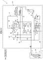
- the outdoor circuit (11) includes a compression unit (20), a switching unit (30), an outdoor heat exchanger (13), an outdoor expansion valve (14), a gas-liquid separator (15), a cooling heat exchanger (16), and an intermediate cooler (17).
- the compression unit (20) compresses the refrigerant.
- the compression unit (20) includes a first compressor (21), a second compressor (22), and a third compressor (23).
- the compression unit (20) is configured as a two-stage compression type.
- the second compressor (22) and the third compressor (23) constitute a low-stage side compressor (low-stage side compression element).
- the second compressor (22) and the third compressor (23) are connected in parallel to each other.
- the first compressor (21) constitutes a high-stage side compressor (high-stage side compression element).
- the first compressor (21) and the second compressor (22) are connected in series to each other.
- the first compressor (21) and the third compressor (23) are connected in series to each other.
- the first compressor (21), the second compressor (22), and the third compressor (23) are rotary compressors whose compression mechanisms are driven by motors.
- the first compressor (21), the second compressor (22), and the third compressor (23) are configured as variable displacement compressors capable of adjusting an operating frequency or a rotational speed.
- the compression unit (20) the refrigerant compressed by the second compressor (22) and the third compressor (23) is further compressed by the first compressor (21).
- a first suction pipe (21a) and a first discharge pipe (21b) are connected to the first compressor (21).
- a second suction pipe (22a) and a second discharge pipe (22b) are connected to the second compressor (22).
- a third suction pipe (23a) and a third discharge pipe (23b) are connected to the third compressor (23).
- the second suction pipe (22a) communicates with the refrigeration-facility unit (50).
- the second compressor (22) is a refrigeration-facility side compressor corresponding to the refrigeration-facility unit (50).
- the third suction pipe (23a) communicates with the indoor unit (60).
- the third compressor (23) is an indoor-side compressor corresponding to the indoor unit (60).
- the switching unit (switching device) (30) switches a flow path of the refrigerant.
- the switching unit (30) includes a first pipe (31), a second pipe (32), a third pipe (33), a fourth pipe (34), a first three-way valve (TV1), and a second three-way valve (TV2).
- An inflow end of the first pipe (31) and an inflow end of the second pipe (32) are connected to the first discharge pipe (21b).
- the first pipe (31) and the second pipe (32) are pipes on which a discharge pressure of the compression unit (20) acts.
- An outflow end of the third pipe (33) and an outflow end of the fourth pipe (34) are connected to the third suction pipe (23a) of the third compressor (23).
- the third pipe (33) and the fourth pipe (34) are pipes on which a suction pressure of the compression unit (20) acts.
- the first three-way valve (TV1) has a first port (PI), a second port (P2), and a third port (P3).
- the first port (P1) of the first three-way valve (TV1) is connected to an outflow end of the first pipe (31) as a high-pressure flow path.
- the second port (P2) of the first three-way valve (TV1) is connected to an inflow end of the third pipe (33) as a low-pressure flow path.
- the third port (P3) of the first three-way valve (TV1) is connected to an indoor gas side flow path (35).
- the second three-way valve (TV2) has a first port (PI), a second port (P2), and a third port (P3).
- the first port (P1) of the second three-way valve (TV2) is connected to an outflow end of the second pipe (32) as a high-pressure flow path.
- the second port (P2) of the second three-way valve (TV2) is connected to an inflow end of the fourth pipe (34) as a low-pressure flow path.
- the third port (P3) of the second three-way valve (TV2) is connected to an outdoor gas side flow path (36).
- the first three-way valve (TV1) and the second three-way valve (TV2) are electric three-way valves.
- the three-way valves (TV1, TV2) switch between a first communication state (state shown by a solid line in FIG. 1 ) and a second communication state (state shown by a broken line in FIG. 1 ).
- the first port (P1) and the third port (P3) communicate with each other, and the second port (P2) is closed.
- the second port (P2) and the third port (P3) communicate with each other, and the first port (P1) is closed.
- the outdoor heat exchanger (13) constitutes a heat source heat exchanger.
- the outdoor heat exchanger (13) is a fin-and-tube air heat exchanger.
- the outdoor fan (12) is disposed near the outdoor heat exchanger (13).
- the outdoor fan (12) conveys outdoor air.
- the outdoor heat exchanger exchanges heat between the refrigerant flowing in the outdoor heat exchanger and the outdoor air conveyed by the outdoor fan (12).
- An outdoor gas side flow path (36) is connected to a gas end of the outdoor heat exchanger (13).
- An outdoor flow path (O) is connected to a liquid end of the outdoor heat exchanger (13).
- the outdoor heat exchanger (13) is a heat exchanger that serves as the radiator during cooling operation and serves as the evaporator during heating operation.
- the outdoor flow path (O) includes an outdoor first pipe (o1), an outdoor second pipe (o2), an outdoor third pipe (o3), an outdoor fourth pipe (o4), an outdoor fifth pipe (o5), an outdoor sixth pipe (o6), and an outdoor seventh pipe (o7).
- One end of the outdoor first pipe (o1) is connected to the liquid end of the outdoor heat exchanger (13).
- One end of the outdoor second pipe (o2) and one end of the outdoor third pipe (o3) are connected to the other end of the outdoor first pipe (o1).
- the other end of the outdoor second pipe (o2) is connected to a top of the gas-liquid separator (15).
- One end of the outdoor fourth pipe (o4) is connected to a bottom of the gas-liquid separator (15).
- One end of the outdoor fifth pipe (o5) and one end of the outdoor third pipe (o3) are connected to the other end of the outdoor fourth pipe (o4).
- the other end of the outdoor fifth pipe (o5) is connected to the first liquid connection pipe (2).
- One end of the outdoor sixth pipe (o6) is connected to a midway of the outdoor fifth pipe (o5).
- the other end of the outdoor sixth pipe (o6) is connected to the second liquid connection pipe (4).
- One end of the outdoor seventh pipe (o7) is connected to a midway of the outdoor sixth pipe (o6).
- One end of the outdoor seventh pipe (o7) is connected to a midway of the outdoor second pipe (o2).
- the outdoor expansion valve (14) is connected to the outdoor first pipe (o1).
- the outdoor expansion valve (14) is a decompression mechanism that decompresses the refrigerant.
- the outdoor expansion valve (14) is a heat source expansion valve.
- the outdoor expansion valve (14) is configured as an electronic expansion valve having a variable opening degree.
- the gas-liquid separator (15) of the present embodiment constitutes a container that stores the refrigerant, and also has a function of a liquid receiver.
- the gas-liquid separator (15) separates the refrigerant into a gas refrigerant and a liquid refrigerant.
- the other end of the outdoor second pipe (o2) and one end of the gas vent pipe (37) are connected to the top of the gas-liquid separator (15).
- the other end of the gas vent pipe (37) is connected to a midway of an injection passage (first gas passage) (38).
- a gas vent valve (first opening and closing device) (39) is connected to the gas vent pipe (37).
- the gas vent valve (39) is configured as an electronic expansion valve having a variable opening degree.
- the gas vent valve (39) may be an openable electromagnetic valve.
- the cooling heat exchanger (16) cools the refrigerant (mainly liquid refrigerant) separated by the gas-liquid separator (15).
- the cooling heat exchanger (16) includes a first refrigerant flow path (16a) and a second refrigerant flow path (16b).
- the first refrigerant flow path (16a) is connected to a midway of the outdoor fourth pipe (o4).
- the second refrigerant flow path (16b) is connected to a midway of the injection passage (38).
- One end of the injection passage (38) is connected to a midway of the outdoor fourth pipe (o4) (on a downstream side of the first refrigerant flow path (16a)).
- the other end of the injection passage (38) is connected to the first suction pipe (21a) of the first compressor (21).
- the other end of the injection passage (38) is connected to a middle pressure part of the compression unit (20).
- the injection passage (38) is provided with a first decompression valve (40) on an upstream side of the second refrigerant flow path (16b).
- the first decompression valve (40) is configured as an expansion valve having a variable opening degree.
- the refrigerant flowing through the first refrigerant flow path (16a) and the refrigerant flowing through the second refrigerant flow path (16b) exchange heat with each other.
- the refrigerant decompressed by the first decompression valve (40) flows through the second refrigerant flow path (16b).
- the cooling heat exchanger (16) cools the refrigerant flowing through the first refrigerant flow path (16a).
- the intermediate cooler (17) is connected to an intermediate flow path (41).
- One end of the intermediate flow path (41) is connected to the second discharge pipe (22b) of the second compressor (22) and the third discharge pipe (23b) of the third compressor (23).
- the other end of the intermediate flow path (41) is connected to the first suction pipe (21a) of the first compressor (21).
- the other end of the intermediate flow path (41) is connected to the middle pressure part of the compression unit (20).
- the intermediate cooler (17) is a fin-and-tube air heat exchanger.
- a cooling fan (17a) is disposed near the intermediate cooler (17).
- the intermediate cooler (17) exchanges heat between the refrigerant flowing in the intermediate cooler and the outdoor air conveyed by the cooling fan (17a).
- the outdoor circuit (11) includes an oil separation circuit (42).
- the oil separation circuit (42) includes an oil separator (43), a first oil return pipe (44), and a second oil return pipe (45).
- the oil separator (43) is connected to the first discharge pipe (21b) of the first compressor (21).
- the oil separator (43) separates oil from the refrigerant discharged from the compression unit (20).
- Inflow ends of the first oil return pipe (44) and the second oil return pipe (45) are connected to the oil separator (43).
- An outflow end of the first oil return pipe (44) is connected to the second suction pipe (22a) of the second compressor (22).
- An outflow end of the second oil return pipe (45) is connected to the third suction pipe (23a) of the third compressor (23).
- a first oil amount regulating valve (46) is connected to the first oil return pipe (44).
- a second oil amount regulating valve (47) is connected to the second oil return pipe (45).
- the oil separated by the oil separator (43) is returned to the second compressor (22) via the first oil return pipe (44).
- the oil separated by the oil separator (43) is returned to the third compressor (23) via the second oil return pipe (45).
- the oil separated by the oil separator (43) may be directly returned to an oil reservoir in a casing of the second compressor (22).
- the oil separated by the oil separator (43) may be directly returned to an oil reservoir in a casing of the third compressor (23).
- a first bypass passage (26) that bypasses the first compressor (21) is connected to the first suction pipe (21a) and the second suction pipe (21b).
- a check valve (27) that allows a flow of the refrigerant from the first suction pipe (21a) to the second suction pipe (21b) and prohibits a flow of the refrigerant in a reverse direction is connected to the first bypass passage (26).
- a second bypass passage (28) is connected to the discharge side flow path (21b) of the first compressor (21) and the second suction side flow path (22a) of the second compressor (22).
- a bypass valve (second opening and closing device) (29) is connected to a second bypass passage (28).
- the bypass valve (29) includes an electronic expansion valve that adjusts a flow rate of the refrigerant in the second bypass passage (28).
- the present embodiment includes a gas passage (70) and an opening and closing device (71).
- the gas passage (70) and the opening and closing device (71) are configured to release the gas refrigerant in the gas-liquid separator (15) to at least one of the plurality of heat exchangers (13, 17, 54, 64). This configuration suppresses an excessive increase in the pressure inside the gas-liquid separator (15).
- the gas passage (70) has the injection passage (38) communicating with a gas outlet (15a) of the gas-liquid separator (15) and an intermediate heat exchanger (17) as the first gas passage for venting the gas refrigerant in the gas-liquid separator (15).
- the gas vent valve (39) provided in the injection passage (38) functions as the first opening and closing device that opens and closes the first gas passage.
- the gas-liquid separator (15) communicates with the intermediate heat exchanger (17) via the injection passage (38) and the intermediate flow path (41).
- the gas passage (70) includes a second gas passage (25) communicating with the heat exchanger having functioned as the evaporator before the compression unit (20) is stopped.
- the second gas passage (25) includes the first bypass passage (26) that bypasses the first compressor (21) and communicates with the first suction pipe (21a) and the second discharge pipe (21b) of the first compressor (21), and includes the second bypass passage (28) that communicates with the first discharge pipe (21b) of the first compressor (21) and the second suction pipe (21a) of the second compressor (22, 23).
- the refrigerant circuit (6) includes the first three-way valve (TV1) and the second three-way valve (TV2) as the switching unit (switching device) (30) that switches a circulation direction of the refrigerant in the refrigerant circuit (6).
- the switching unit (30) is switchable between a first state, a second state, and a third state.
- the first three-way valve (TV1) and the second three-way valve (TV2) are switched such that the indoor heat exchanger (64) to be described later communicates with the third suction pipe (23a) of the compression unit (20), and the outdoor heat exchanger (13) communicates with the first discharge pipe (21b) of the compression unit (20).
- the first three-way valve (TV1) and the second three-way valve (TV2) are switched such that the indoor heat exchanger (64) communicates with the first discharge pipe (21b) of the compression unit (20), and the outdoor heat exchanger (13) communicates with the third suction pipe (23a) of the compression unit (20).
- the first three-way valve (TV1) and the second three-way valve (TV2) are switched such that the indoor heat exchanger (64) and the outdoor heat exchanger (13) communicate with each other.
- the gas passage (70) communicates with the indoor heat exchanger (64) and the outdoor heat exchanger (13).
- the gas-liquid separator (15) communicates with the indoor heat exchanger (64) via the injection passage (38), the first bypass passage (26), the indoor gas side flow path (35), and the second gas connection pipe (5).
- the gas refrigerant in the gas-liquid separator (15) flows into the indoor heat exchanger (64) serving as the evaporator before the compression unit (20) is stopped.
- the outdoor heat exchanger (13) serves as the evaporator before the compression unit (20) is stopped
- the gas-liquid separator (15) communicates with the outdoor heat exchanger (13) via the injection passage (38), the first bypass passage (26), and the outdoor gas side flow path (36).
- the gas refrigerant in the gas-liquid separator (15) flows into the outdoor heat exchanger (13) serving as the evaporator before the compression unit (20) is stopped.
- the outdoor circuit (11) includes a first check valve (CV1), a second check valve (CV2), a third check valve (CV3), a fourth check valve (CV4), a fifth check valve (CV5), a sixth check valve (CV6), and a seventh check valve (CV7).
- the first check valve (CV1) is connected to the first discharge pipe (21b).
- the second check valve (CV2) is connected to the second discharge pipe (22b).
- the third check valve (CV3) is connected to the third discharge pipe (23b).
- the fourth check valve (CV4) is connected to the outdoor second pipe (o2).
- the fifth check valve (CV5) is connected to the outdoor third pipe (o3).
- the sixth check valve (CV6) is connected to the outdoor sixth pipe (o6).
- the seventh check valve (CV7) is connected to the outdoor seventh pipe (o7).
- Each of the check valves (CV1 to CV7) allows the refrigerant to flow in the direction indicated by an arrow in FIG. 1 , and prohibits the flow of the refrigerant in an opposite direction to the arrow.
- the refrigeration-facility unit (50) is, for example, a utilization unit (utilization side apparatus) installed in a refrigerating warehouse.
- the refrigeration-facility unit (50) includes an interior fan (52) and a refrigeration-facility circuit (51).
- the first liquid connection pipe (2) is connected to a liquid end of the refrigeration-facility circuit (51).
- the first gas connection pipe (3) is connected to a gas end of the refrigeration-facility circuit (51).
- the refrigeration-facility circuit (51) includes, in order from a liquid end to a gas end, a refrigeration-facility expansion valve (53) and a refrigeration-facility heat exchanger (heat exchanger for refrigeration equipment) (54).
- the refrigeration-facility expansion valve (53) is a first utilization expansion valve.
- the refrigeration-facility expansion valve (53) is an electronic expansion valve having a variable opening degree.
- the refrigeration-facility heat exchanger (54) is a first utilization heat exchanger.
- the refrigeration-facility heat exchanger (54) is a fin-and-tube air heat exchanger.
- the interior fan (52) is disposed near the refrigeration-facility heat exchanger (54).
- the interior fan (52) conveys interior air.
- the refrigeration-facility heat exchanger (54) exchanges heat between the refrigerant flowing in the refrigeration-facility heat exchanger and the interior air conveyed by the interior fan (52).
- the indoor unit (60) is a utilization unit (utilization side apparatus) installed indoors.
- the indoor unit (60) includes an indoor fan (62) and an indoor circuit (61).
- the second liquid connection pipe (4) is connected to a liquid end of the indoor circuit (61).
- the second gas connection pipe (15) is connected to a gas end of the indoor circuit (61).
- the indoor circuit (61) includes, in order from a liquid end to a gas end, an indoor expansion valve (63) and the indoor heat exchanger (air conditioning heat exchanger) (64).
- the indoor expansion valve (63) is a second utilization expansion valve.
- the indoor expansion valve (63) is an electronic expansion valve having a variable opening degree.
- the indoor heat exchanger (64) is a second utilization heat exchanger.
- the indoor heat exchanger (64) is a fin-and-tube air heat exchanger.
- the indoor fan (62) is disposed near the indoor heat exchanger (64).
- the indoor fan (62) conveys indoor air.
- the indoor heat exchanger (64) exchanges heat between the refrigerant flowing in the indoor heat exchanger and the indoor air conveyed by the indoor fan (62).
- the indoor heat exchanger (64) is a heat exchanger that serves as the radiator during heating operation and serves as the evaporator during cooling operation.
- the refrigeration apparatus (1) includes various sensors (not shown). Examples of indices detected by these sensors include a temperature and a pressure of high-pressure refrigerant in the refrigerant circuit (6), a temperature and a pressure of refrigerant in the gas-liquid separator (15), a temperature and a pressure of low-pressure refrigerant, a temperature and a pressure of intermediate-pressure refrigerant, a temperature of refrigerant in the outdoor heat exchanger (13), a temperature of refrigerant in the refrigeration-facility heat exchanger (54), a temperature of refrigerant in the indoor heat exchanger (64), a degree of superheating of sucked refrigerant in the second compressor (22), a degree of superheating of sucked refrigerant in the third compressor (23), a temperature of the outdoor air, a temperature of the interior air, and a temperature of the indoor air.
- indices detected by these sensors include a temperature and a pressure of high-pressure refrigerant in the refriger
- the controller (100) serving as a controller includes a microcomputer mounted on a control board and a memory device (specifically, a semiconductor memory) that stores software for operating the microcomputer.
- the controller (100) controls each device of the refrigeration apparatus (1) on the basis of an operation command and detection signals of the sensors. The operation of the refrigeration apparatus (1) is switched through control of each device by the controller (100).
- the controller (100) is connected to various sensors including a temperature sensor that detects the temperature of the high-pressure refrigerant in the refrigerant circuit (6) via a communication line.
- the controller (100) is connected to components of the refrigerant circuit (6) including the first compressor (21), the second compressor (22), the third compressor (23), and the like via the communication line.
- the controller (100) closes the opening and closing device (71) when the pressure in the gas-liquid separator (15) is equal to or less than a predetermined value in a state where the compression unit (20) is stopped, and opens the opening and closing device (71) when the pressure in the gas-liquid separator (15) is higher than the predetermined value.
- the pressure in the gas-liquid separator (15) is higher than the predetermined value while the compression unit (20) is stopped, the refrigerant in the gas-liquid separator (15) flows into the intermediate heat exchanger (17).
- the predetermined value is set to, for example, about 8 MPa. Details of the control will be described later with reference to a flowchart.
- the controller (100) opens the bypass valve (29) as the second opening and closing device.
- the gas-liquid separator (15) communicates with the refrigeration-facility heat exchanger (54) via the injection passage (38), the first bypass passage (26), and the second bypass passage (28).
- the gas refrigerant in the gas-liquid separator (15) is introduced into the refrigeration-facility heat exchanger (54) having functioned as the evaporator before the compression unit (20) is stopped.
- the controller (100) also performs control to switch the switching unit (30) to the third state and allow the gas passage (70) to communicate with the indoor heat exchanger (64) and the outdoor heat exchanger (13).
- the operation of the refrigeration apparatus (1) includes refrigeration-facility operation, cooling operation, cooling and refrigeration-facility operation, heating operation, heating and refrigeration-facility operation, heating and refrigeration-facility heat recovery operation, heating and refrigeration-facility residual heat operation, and defrost operation.
- the refrigeration-facility unit (50) is operated and the indoor unit (60) is stopped.
- the refrigeration-facility unit (50) is stopped and the indoor unit (60) performs cooling.
- the refrigeration-facility unit (50) is operated and the indoor unit (60) performs cooling.
- the refrigeration-facility unit (50) is stopped and the indoor unit (60) performs heating.
- the refrigeration-facility unit (50) is operated and the indoor unit (60) performs heating.
- the refrigeration-facility unit (50) is operated to melt frost on the surface of the outdoor heat exchanger (13).
- the heating and refrigeration-facility operation is executed under the condition that a required heating capacity of the indoor unit (60) is relatively high.
- the heating and refrigeration-facility residual heat operation is executed under the condition that the required heating capacity of the indoor unit (60) is relatively low.
- the heating and refrigeration-facility heat recovery operation is executed under the condition that the required heating capacity of the indoor unit (60) is the required heating capacity during the heating and refrigeration-facility operation (condition that the refrigeration-facility operation and the heating operation are balanced).
- the first three-way valve (TV1) is in the second communication state
- the second three-way valve (TV2) is in the first communication state.
- the outdoor expansion valve (14) is opened at a predetermined opening degree, the opening degree of the refrigeration-facility expansion valve (53) is adjusted through superheating control, the indoor expansion valve (63) is fully closed, and the opening degree of the first decompression valve (40) is appropriately adjusted.
- the outdoor fan (12) and the interior fan (52) are operated, and the indoor fan (62) is stopped.
- the first compressor (21) and the second compressor (22) are operated, and the third compressor (23) is stopped.
- a refrigeration cycle is performed in which the refrigerant compressed in the compression unit (20) radiates heat in the outdoor heat exchanger (13) and evaporates in the refrigeration-facility heat exchanger (54).
- the refrigerant compressed in the second compressor (22) is cooled by the intermediate cooler (17) and then sucked into the first compressor (21).
- the refrigerant compressed in the first compressor (21) radiates heat in the outdoor heat exchanger (13), flows through the gas-liquid separator (15), and is cooled in the first refrigerant flow path (16a) of the cooling heat exchanger (16).
- the refrigerant in the second refrigerant flow path (16b) that has cooled the refrigerant in the first refrigerant flow path (16a) flows through the injection passage (38) and is sucked into the first compressor (21).
- the refrigerant cooled in the first refrigerant flow path (16a) of the cooling heat exchanger (16) is decompressed by the refrigeration-facility expansion valve (53) and then evaporates in the refrigeration-facility heat exchanger (54). As a result, the interior air is cooled.
- the refrigerant having evaporated in the cooling heat exchanger (16) is sucked into the second compressor (22) to be compressed again.
- the first three-way valve (TV1) is in the second communication state
- the second three-way valve (TV2) is in the first communication state.
- the outdoor expansion valve (14) is opened at a predetermined opening degree
- the refrigeration-facility expansion valve (53) is fully closed
- the opening degree of the indoor expansion valve (63) is adjusted through superheating control
- the opening degree of the first decompression valve (40) is appropriately adjusted.
- the outdoor fan (12) and the indoor fan (62) are operated, and the interior fan (52) is stopped.
- the first compressor (21) and the third compressor (23) are operated, and the second compressor (22) is stopped.
- a refrigeration cycle is performed in which the refrigerant compressed in the compression unit (20) radiates heat in the outdoor heat exchanger (13) and evaporates in the indoor heat exchanger (64).
- the refrigerant compressed in the third compressor (23) is cooled by the intermediate cooler (17) and then sucked into the first compressor (21).
- the refrigerant compressed in the first compressor (21) radiates heat in the outdoor heat exchanger (13), flows through the gas-liquid separator (15), and is cooled in the first refrigerant flow path (16a) of the cooling heat exchanger (16).
- the refrigerant in the second refrigerant flow path (16b) that has cooled the refrigerant in the first refrigerant flow path (16a) flows through the injection passage (38) and is sucked into the first compressor (21).
- the refrigerant cooled in the first refrigerant flow path (16a) of the cooling heat exchanger (16) is decompressed by the indoor expansion valve (63) and then evaporates in the indoor heat exchanger (64). As a result, the indoor air is cooled.
- the refrigerant having evaporated in the indoor heat exchanger (64) is sucked into the third compressor (23) to be compressed again.
- the first three-way valve (TV1) is in the second communication state
- the second three-way valve (TV2) is in the first communication state.
- the outdoor expansion valve (14) is opened at a predetermined opening degree
- the opening degrees of the refrigeration-facility expansion valve (53) and the indoor expansion valve (63) are adjusted through superheating control, and the opening degree of the first decompression valve (40) is appropriately adjusted.
- the outdoor fan (12), the interior fan (52), and the indoor fan (62) are operated.
- the first compressor (21), the second compressor (22), and the third compressor (23) are operated.
- a refrigeration cycle is performed in which the refrigerant compressed in the compression unit (20) radiates heat in the outdoor heat exchanger (13) and evaporates in the refrigeration-facility heat exchanger (54) and the indoor heat exchanger (64).
- the refrigerant compressed in the second compressor (22) and the third compressor (23) is sucked into the first compressor (21).
- the refrigerant compressed in the first compressor (21) radiates heat in the outdoor heat exchanger (13), flows through the gas-liquid separator (15), and is cooled in the first refrigerant flow path (16a) of the cooling heat exchanger (16).
- the refrigerant in the second refrigerant flow path (16b) that has cooled the refrigerant in the first refrigerant flow path (16a) flows through the injection passage (38) and is sucked into the first compressor (21).
- the refrigerant cooled in first refrigerant flow path (16a) of cooling heat exchanger (16) is divided into refrigeration-facility unit (50) and indoor unit (60).
- the refrigerant decompressed by the refrigeration-facility expansion valve (53) evaporates in the refrigeration-facility heat exchanger (54).
- the refrigerant having evaporated in the refrigeration-facility heat exchanger (54) is sucked into the second compressor (22) to be compressed again.
- the refrigerant decompressed by the indoor expansion valve (63) evaporates in the indoor heat exchanger (64).
- the refrigerant having evaporated in the indoor heat exchanger (64) is sucked into the third compressor (23) to be compressed again.
- the first three-way valve (TV1) is in the first communication state
- the second three-way valve (TV2) is in the second communication state.
- the indoor expansion valve (63) is opened at a predetermined opening degree
- the refrigeration-facility expansion valve (53) is fully closed
- the opening degree of the outdoor expansion valve (14) is adjusted through superheating control
- the opening degree of the first decompression valve (40) is appropriately adjusted.
- the outdoor fan (12) and the indoor fan (62) are operated, and the interior fan (52) is stopped.
- the first compressor (21) and the third compressor (23) are operated, and the second compressor (22) is stopped.
- a refrigeration cycle is performed in which the refrigerant compressed in the compression unit (20) radiates heat in the indoor heat exchanger (64) and evaporates in the outdoor heat exchanger (13).
- the refrigerant compressed in the third compressor (23) is sucked into the first compressor (21).
- the refrigerant compressed in the first compressor (21) radiates heat in the indoor heat exchanger (64).
- the refrigerant having radiated heat in the indoor heat exchanger (64) flows through the gas-liquid separator (15), and is cooled in the first refrigerant flow path (16a) of the cooling heat exchanger (16).
- the refrigerant in the second refrigerant flow path (16b) that has cooled the refrigerant in the first refrigerant flow path (16a) flows through the injection passage (38) and is sucked into the first compressor (21).
- the refrigerant cooled in the first refrigerant flow path (16a) of the cooling heat exchanger (16) is decompressed by the outdoor expansion valve (14) and then evaporates in the outdoor heat exchanger (13).
- the refrigerant having evaporated in the outdoor heat exchanger (13) is sucked into the third compressor (23) to be compressed again.
- the first three-way valve (TV1) is in the first communication state and the second three-way valve (TV2) is in the second communication state.
- the indoor expansion valve (63) is opened at a predetermined opening degree, the opening degrees of the refrigeration-facility expansion valve (53) and the outdoor expansion valve (14) are adjusted through superheating control, and the opening degree of the first decompression valve (40) is appropriately adjusted.
- the outdoor fan (12), the interior fan (52), and the indoor fan (62) are operated.
- the first compressor (21), the second compressor (22), and the third compressor (23) are operated.
- a refrigeration cycle is performed in which the refrigerant compressed in the compression unit (20) radiates heat in the indoor heat exchanger (64) and evaporates in the refrigeration-facility heat exchanger (54) and the outdoor heat exchanger (13).
- the refrigerant compressed in the second compressor (22) and the third compressor (23) is sucked into the first compressor (21).
- the refrigerant compressed in the first compressor (21) radiates heat in the indoor heat exchanger (64).
- the refrigerant having radiated heat in the indoor heat exchanger (64) flows through the gas-liquid separator (15), and is cooled in the first refrigerant flow path (16a) of the cooling heat exchanger (16).
- the refrigerant in the second refrigerant flow path (16b) that has cooled the refrigerant in the first refrigerant flow path (16a) flows through the injection passage (38) and is sucked into the first compressor (21).
- the rest of the refrigerant cooled in the first refrigerant flow path (16a) of the cooling heat exchanger (16) is decompressed by the refrigeration-facility expansion valve (53) and then evaporates in the refrigeration-facility heat exchanger (54). As a result, the interior air is cooled.
- the refrigerant having evaporated in the refrigeration-facility heat exchanger (54) is sucked into the second compressor (22) to be compressed again.
- the first three-way valve (TV1) is in the first communication state
- the second three-way valve (TV2) is in the second communication state.
- the indoor expansion valve (63) is opened at a predetermined opening degree
- the outdoor expansion valve (14) is fully closed
- the opening degree of the refrigeration-facility expansion valve (53) is adjusted through superheating control
- the opening degree of the first decompression valve (40) is appropriately adjusted.
- the indoor fan (62) and the interior fan (52) are operated, and the outdoor fan (12) is stopped.
- the first compressor (21) and the second compressor (22) are operated, and the third compressor (23) is stopped.
- a refrigeration cycle is performed in which the refrigerant compressed in the compression unit (20) radiates heat in the indoor heat exchanger (64) and evaporates in the refrigeration-facility heat exchanger (54), and the outdoor heat exchanger (13) is substantially stopped.
- the refrigerant compressed in the second compressor (22) is sucked into the first compressor (21).
- the refrigerant compressed in the first compressor (21) radiates heat in the indoor heat exchanger (64).
- the refrigerant having radiated heat in the indoor heat exchanger (64) flows through the gas-liquid separator (15), and is cooled in the first refrigerant flow path (16a) of the cooling heat exchanger (16).
- the refrigerant in the second refrigerant flow path (16b) that has cooled the refrigerant in the first refrigerant flow path (16a) flows through the injection passage (38) and is sucked into the first compressor (21).
- the refrigerant cooled in the first refrigerant flow path (16a) of the cooling heat exchanger (16) is decompressed by the refrigeration-facility expansion valve (53) and then evaporates in the refrigeration-facility heat exchanger (54).
- the refrigerant having evaporated in the refrigeration-facility heat exchanger (54) is sucked into the second compressor (22) to be compressed again.
- the first three-way valve (TV1) is in the first communication state
- the second three-way valve (TV2) is in the second communication state.
- the indoor expansion valve (63) and the outdoor expansion valve (14) are opened at a predetermined opening degree, the opening degree of the refrigeration-facility expansion valve (53) is adjusted through superheating control, and the opening degree of the first decompression valve (40) is appropriately adjusted.
- the outdoor fan (12), the interior fan (52), and the indoor fan (62) are operated.
- the first compressor (21) and the second compressor (22) are operated, and the third compressor (23) is stopped.
- a refrigeration cycle is performed in which the refrigerant compressed in the compression unit (20) radiates heat in the indoor heat exchanger (64) and the outdoor heat exchanger (13) and evaporates in the refrigeration-facility heat exchanger (54).
- the refrigerant compressed in the second compressor (22) is sucked into the first compressor (21).
- Part of the refrigerant compressed in the first compressor (21) radiates heat in the outdoor heat exchanger (13).
- the rest of the refrigerant compressed in the first compressor (21) radiates heat in the indoor heat exchanger (64).
- the indoor air is heated.
- the refrigerant having radiated heat in the outdoor heat exchanger (13) and the refrigerant having radiated heat in the indoor heat exchanger (64) merge with each other, then flow through the gas-liquid separator (15), and are cooled in the first refrigerant flow path (16a) of the cooling heat exchanger (16).
- the refrigerant in the second refrigerant flow path (16b) that has cooled the refrigerant in the first refrigerant flow path (16a) flows through the injection passage (38) and is sucked into the first compressor (21).
- the refrigerant cooled in the first refrigerant flow path (16a) of the cooling heat exchanger (16) is decompressed by the refrigeration-facility expansion valve (53) and then evaporates in the refrigeration-facility heat exchanger (54). As a result, the interior air is cooled.
- the refrigerant having evaporated in the refrigeration-facility heat exchanger (54) is sucked into the second compressor (22) to be compressed again.
- the same operation as the cooling operation illustrated in FIG. 4 is performed in the defrost operation.
- the refrigerant compressed in the second compressor (22) and the first compressor (21) radiates heat in the outdoor heat exchanger (13).
- frost on the surface of the outdoor heat exchanger (13) is heated from inside.
- the refrigerant that has been used for defrosting the outdoor heat exchanger (13) evaporates in the indoor heat exchanger (64), and then is sucked into the second compressor (22) to be compressed again.
- gas vent control of the gas-liquid separator (15) is performed when outside air temperature is higher than a critical point temperature of the refrigerant in a state where the compressor is stopped.
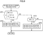
- FIG. 9 is a flowchart illustrating an example of the gas vent control.
- FIG. 10 is a flowchart illustrating control of the switching unit (30) performed during the gas vent control.
- step ST1 it is determined whether any one of the following two conditions is satisfied.
- a first condition is that a pressure RP in the gas-liquid separator (15) is higher than 8.3 (MPa).
- a second condition is that the pressure RP in the gas-liquid separator (15) is higher than 8.0 (MPa) and an outside air temperature Ta is higher than 30 (°C).
- MPa 8.3
- Ta outside air temperature
- step ST2 an opening degree signal of, for example, 70 pulses is transmitted to a pulse motor of the gas vent valve (39) to adjust a valve opening degree, and the processing returns to step ST1.
- the opening degree of the gas vent valve (39) as described above, the refrigerant in the gas-liquid separator (15) passes through the intermediate flow path (41) from the injection passage (38) as the first gas passage and flows into the intermediate heat exchanger (13) while the compression unit (20) is stopped. As a result, the pressure inside the gas-liquid separator (15) decreases.
- the bypass valve (29) of the second bypass passage (28) is controlled to be opened.
- the refrigeration-facility heat exchanger (54) serves as the evaporator before the compression unit (20) is stopped
- the refrigerant in the gas-liquid separator (15) also flows into the refrigeration-facility heat exchanger (54).
- the refrigerant in the gas-liquid separator (15) flows into the refrigeration-facility heat exchanger (54) through the injection passage (38), the first suction pipe (21a), the first bypass passage (26), the second bypass passage (28), and the first gas connection pipe (3).
- the pressure inside the gas-liquid separator (15) further decreases.
- step ST3 it is determined whether the pressure RP of the gas-liquid separator (15) is lower than 7.5 (MPa).
- step ST4 it is determined that the pressure inside the gas-liquid separator (15) is lower than the critical pressure, and the processing proceeds to step ST4.
- step ST4 an opening degree signal of 0 pulse is transmitted to the pulse motor of the gas vent valve (39), and the gas vent valve (39) is closed. In this state, the refrigerant in the gas-liquid separator (15) does not flow into any heat exchanger.
- step ST4 After the control in step ST4, the processing returns to step ST1.
- step ST3 When the condition in step ST3 is not satisfied, the control of the gas vent valve (39) is not performed, the processing returns to step ST1, and the control in steps ST1 to ST4 is repeated.
- step ST11 When the condition in step ST11 is satisfied, the processing proceeds to step ST12, and it is determined whether the first three-way valve (TV1) is in the second communication state.
- the processing proceeds to step ST13, and the first three-way valve (TV2) is switched to the first communication state.
- step ST14 the processing waits for 20 seconds to elapse in this state, and returns to step ST11.
- step ST15 When the first three-way valve (TV1) is not in the second communication state upon determination in step ST12, it is determined in step ST15 whether the second three-way valve (TV2) is in the second communication state. When the second three-way valve (TV2) is in the second communication state, the second three-way valve (TV2) is switched to the first communication state in step ST16, the processing waits for 20 seconds to elapse in this state in step ST17, and returns to step ST11. When the second three-way valve (TV2) is not in the second communication state upon determination in step ST15, neither the first three-way valve (TV1) nor the second three-way valve (TV2) is switched, and the processing returns to step ST11.
- both the first three-way valve (TV1) and the second three-way valve (TV2) enter the first communication state, and the outdoor heat exchanger (13) and the indoor heat exchanger (64) communicate with each other.
- the refrigerant in the radiator flows into the evaporator to equalize the pressure therebetween.
- the gas vent valve (39) and the bypass valve (29) are opened as described above, the refrigerant in the gas-liquid separator (15) flows into the outdoor heat exchanger (13) and the indoor heat exchanger (64) including the heat exchanger serving as the evaporator before the compression unit (20) is stopped.
- the gas passage (70) that communicates with the gas outlet (15a) of the gas-liquid separator (15) and at least one of a plurality of heat exchangers (13, 17, 54, 64), the opening and closing device (71) that opens and closes the gas passage (70), and the controller (100) that closes the opening and closing device (71) when the pressure in the gas-liquid separator (15) is equal to or less than a predetermined value in a state where the compression unit (20) is stopped, and opens the opening and closing device (71) when the pressure in the gas-liquid separator (15) is higher than the predetermined value.
- the refrigerant when the outside air temperature becomes equal to or higher than the critical point temperature (about 32°C), the refrigerant is vaporized to increase the volume. Therefore, the pressure in the gas-liquid separator (15) increases.
- the cooling load on a utilization side usually increases, but the cooling load may be small in some cases. In such a case, excessive refrigerant is likely to be generated, and in particular, the refrigerant in the gas-liquid separator (15) becomes excessive, and pressure abnormality inside the gas-liquid separator (15) may occur.
- the opening and closing device (71) of the gas passage (70) is opened when the pressure in the gas-liquid separator (15) is higher than a predetermined value in a state where the compression unit (20) is stopped.
- the refrigerant in the gas-liquid separator (15) can be released to at least one of the heat exchangers (13, 17, 54, 64). It is therefore possible to suppress the occurrence of pressure abnormality inside the gas-liquid separator (15) while the compression unit (20) is stopped without increasing the internal volume of the gas-liquid separator (15) or using a dedicated container such as an expansion tank. Accordingly, an increase in size and complexity of the apparatus can be suppressed.
- the pressure inside the gas-liquid separator (15) can be reduced, the pressure resistance of the gas-liquid separator (15) does not need to be enhanced more than necessary.
- the pressure in the gas-liquid separator (15) can be detected by providing a pressure sensor in a pipe of a liquid-refrigerant outlet of the gas-liquid separator (15).
- the compression unit (20) includes the low-stage side compression element (22, 23) and the high-stage side compression element (21) that further compresses the refrigerant compressed by the low-stage side compression element (22, 23).
- the plurality of heat exchangers (13, 17, 54, 64) include the intermediate heat exchanger (17) provided between the low-stage side compression element (22, 23) and the high-stage side compression element (21).
- the gas passage (70) includes the injection passage (first gas passage) (38) communicating with the gas-liquid separator (15) and the intermediate heat exchanger (17), and the opening and closing device (71) includes the gas vent valve (first opening and closing device) (39) provided in the first gas passage (38).
- the gas vent valve (39) provided in the injection passage (38) is opened when the pressure in the gas-liquid separator (15) is higher than a predetermined value in a state where the compression unit (20) is stopped.
- the refrigerant in the gas-liquid separator (15) flows into the intermediate heat exchanger (17). It is therefore possible to suppress the occurrence of pressure abnormality inside the gas-liquid separator (15) without using an expansion tank or the like.
- the plurality of heat exchangers (13, 17, 54, 64) include a radiator and an evaporator that constitute the refrigeration cycle of the refrigerant circuit (6), and the gas passage (70) includes the second gas passage (28) communicating with the heat exchanger having functioned as an evaporator before the compression unit (20) is stopped when the pressure in the gas-liquid separator (15) is higher than the predetermined value.
- the opening and closing device (71) of the gas passage (70) is opened when the pressure in the gas-liquid separator (15) is higher than the predetermined value in a state where the compression unit (20) is stopped. Since the gas passage (70) includes the second gas passage (28), the refrigerant in the gas-liquid separator (15) flows into the heat exchanger having functioned as the evaporator before the compression unit (20) is stopped. It is therefore possible to suppress the occurrence of pressure abnormality inside the gas-liquid separator (15) without using a dedicated container such as an expansion tank.
- the second gas passage (25) includes the first bypass passage (26) that bypasses the high-stage side compression element (21) and communicates with the suction side flow path (21a) and the discharge side flow path (21b) of the high-stage side compression element (21), and the second bypass passage (28) that communicates with the discharge side flow path (21b) of the high-stage side compression element (21) and the suction side flow path (22a) of the low-stage side compression element (22).
- the opening and closing device (71) includes the bypass valve (second opening and closing device) (29) provided in the second bypass passage (28).
- the compression unit (20) has the low-stage side compression element (22, 23) and the high-stage side compression element (21)
- the gas vent valve (39) of the injection passage (38) and the bypass valve (29) of the second bypass passage (28) are opened.
- the first gas passage (38) communicates with the intermediate heat exchanger (17) and also communicates with the suction side flow path (21a) of the high-stage side compression element (21).
- the refrigerant in the gas-liquid separator (15) bypasses the first compressor (21) from the suction side flow path (21a), passes through the first bypass passage, further passes through the second bypass passage (28), and flows into the suction side flow path (22a) of the second compressor (22). Since the suction side flow path (22a) of the second compressor (22) communicates with the refrigeration-facility heat exchanger (54), the refrigerant flows into the refrigeration-facility heat exchanger (54) serving as the evaporator before the compression unit (20) is stopped. It is therefore possible to suppress the occurrence of pressure abnormality inside the gas-liquid separator (15) without using an expansion tank or the like.
- the controller (100) opens the first opening and closing device (39) to cause the gas refrigerant in the gas-liquid separator (15) to be introduced into the intermediate heat exchanger (17).
- the controller (100) opens the second opening and closing device (29).
- the refrigerant in the gas-liquid separator (15) flows into the intermediate heat exchanger (17), and then flows into the refrigeration-facility heat exchanger (54) serving as an evaporator before the compression unit (20) is stopped.
- the refrigerant sequentially flows into the intermediate heat exchanger (17) and the refrigeration-facility heat exchanger (54) serving as the evaporator before the compression unit (20) is stopped, and thus the occurrence of pressure abnormality inside the gas-liquid separator (15) can be more effectively suppressed.
- the refrigerant circuit (6) includes the outdoor heat exchanger (13), the refrigeration-facility heat exchanger (54), the indoor heat exchanger (64), and the switching unit (30) that switches the circulation direction of the refrigerant in the refrigerant circuit (6).
- the switching unit (30) can be set to the first state in which the indoor heat exchanger (64) communicates with the suction side flow path (21a) of the compression unit (20) and the outdoor heat exchanger (13) communicates with the discharge side flow path (21b) of the compression unit (20).
- the switching unit (30) can be set to the second state in which the indoor heat exchanger (64) communicates with the discharge side flow path (21b) of the compression unit (20) and the outdoor heat exchanger (13) communicates with the suction side flow path (21a) of the compression unit (20).
- the switching unit (30) can also be switched to the third state in which the indoor heat exchanger (64) and the outdoor heat exchanger (13) communicate with each other.
- the gas passage (70) communicates with the indoor heat exchanger (64) and the outdoor heat exchanger (13).
- the opening and closing device (71) of the gas passage (70) is opened when the pressure in the gas-liquid separator (15) is higher than the predetermined value in a state where the compression unit (20) is stopped.
- the gas passage communicates with both the indoor heat exchanger (64) and the outdoor heat exchanger (13). Accordingly, the indoor heat exchanger (64) and the outdoor heat exchanger (13) are equalized in pressure.
- the refrigerant of the gas-liquid separator (15) flows into the heat exchanger serving as the evaporator and the other heat exchanger. It is therefore possible to suppress the occurrence of pressure abnormality inside the gas-liquid separator (15) while the compression unit (20) is stopped.
- the first oil return pipe (44) connected to the oil separator (43) and the second suction pipe (22a) can be used as a second bypass passage communicating with the gas-liquid separator (15) and the refrigeration-facility heat exchanger (54).
- the first oil amount regulating valve (46) is opened instead of opening the second bypass valve (29) in the first embodiment.
- the refrigerant flows into the refrigeration-facility heat exchanger (54) through the first oil return pipe (44) functioning as the second bypass passage.
- the second oil return pipe (45) connected to the oil separator (43) and the third suction pipe (23a) can be used as a second bypass passage communicating with the gas-liquid separator (15) and the outdoor heat exchanger (13).
- the second oil amount regulating valve (47) is opened instead of opening the second bypass valve (29) in the first embodiment.
- the refrigerant flows into the outdoor heat exchanger (13) through the second oil return pipe (45) functioning as the second bypass passage.
- FIG. 11 A second embodiment illustrated in FIG. 11 will be described.
- the refrigeration apparatus (1) according to the second embodiment is identical to the refrigeration apparatus according to the first embodiment in that the refrigeration apparatus (1) includes the outdoor unit (10) and the refrigeration-facility unit (50). However, the refrigeration apparatus (1) according to the second embodiment does not include the indoor unit (60) configured to air-condition a room.
- the refrigerant circuit (6) the refrigerant circulates only in a direction in which the refrigerant sequentially flows through the compression unit (20), the outdoor heat exchanger (13), the gas-liquid separator (15), the cooling heat exchanger (16), and the refrigeration-facility heat exchanger (54). Therefore, in the second embodiment, the switching unit (30) according to the first embodiment that reverses the circulation direction of the refrigerant is not provided.
- Other device configurations in the refrigerant circuit (6) of the refrigeration apparatus (1) are similar to those of the first embodiment.
- a refrigeration cycle in which the outdoor heat exchanger (13) functions as the radiator and the refrigeration-facility heat exchanger (54) functions as the evaporator.
- the opening and closing device (71) of the gas passage (70) is opened when the pressure in the gas-liquid separator (15) is higher than a predetermined value in a state where the compression unit (20) is stopped.
- the refrigerant in the gas-liquid separator (15) can be released to at least one of the heat exchangers (17, 54) (the intermediate heat exchanger (17) and the refrigeration-facility heat exchanger (54) serving as the evaporator before the compression unit (20) is stopped). It is therefore possible to suppress the occurrence of pressure abnormality inside the gas-liquid separator (15) while the compression unit (20) is stopped without increasing the internal volume of the gas-liquid separator (15) or using a dedicated container such as an expansion tank. Accordingly, an increase in size and complexity of the apparatus can be suppressed.
- the pressure inside the gas-liquid separator (15) can be reduced, the pressure resistance of the gas-liquid separator (15) does not need to be enhanced more than necessary.
- the above embodiments may adopt the following configurations.
- the gas-liquid separator (15) and the intermediate heat exchanger (17) communicate with each other via the injection passage (first gas passage) (38)
- the gas-liquid separator (15) and the refrigeration-facility heat exchanger (54) communicate with each other via the injection passage (first gas passage) (38) and the second gas passage (25) (the first bypass passage (26) and the second bypass passage (28))
- the gas-liquid separator (15) and the outdoor heat exchanger (13) communicate with each other via the injection passage (first gas passage) (38) and the second gas passage (25) (the first bypass passage (26) and the second oil return pipe (second bypass passage) (45)).
- the gas-liquid separator (15) communicates with the outdoor heat exchanger (13) and the indoor heat exchanger (64) via the injection passage (first gas passage) (38) and the first bypass passage (26) in a state where the outdoor heat exchanger (13) and the indoor heat exchanger (64) communicate with each other via the switching unit (30).
- the gas-liquid separator (15) does not need to communicate with all of the plurality of heat exchangers (13, 17, 54, 64), but may need to communicate with at least one of the plurality of heat exchangers (13, 17, 54, 64).
- the compression unit (20) includes the high-stage side compressor (21) and the low-stage side compressor (22, 23).
- the compression unit (20) may be configured such that the high-stage side compression element and the low-stage side compression element are accommodated in a casing of one compressor.
- the compression unit (20) includes the low-stage side compression element (22, 23) and the high-stage side compression element (21) that further compresses the refrigerant compressed by the low-stage side compression element (22, 23), and in this configuration, the refrigerant in the gas-liquid separator (15) can be released to the intermediate heat exchanger (17).
- the gas passage (70) when the pressure in the gas-liquid separator (15) is higher than the predetermined value, the gas passage (70) may communicate with the heat exchanger having functioned as the evaporator before the compression unit (20) is stopped.
- first bypass passage (26) and the second bypass passages (28, 44) (45) may be provided without providing the intermediate heat exchanger (17) in the refrigerant circuit (6) in FIG. 1 .
- the gas passage (70) may be a passage communicating with the gas-liquid separator (15) and the suction pipe (22a, 23a) of the low-stage compression element (22, 23) without providing the first bypass passage (26) and the second bypass passage (28, 44) (45).
- the switching unit (30) includes two three-way valves (TV1, TV2), but the switching unit (30) may be configured by using two four-way switching valves of an electric switching type instead of the three-way valves and by closing one port of each of the four-way switching valves. Instead of the three-way valves (TV1, TV2), the switching unit (30) may be configured by combining a plurality of electromagnetic valves.
- the refrigerant is not limited to carbon dioxide.
- the refrigerant may be any refrigerant as long as the high pressure of the refrigerant circuit is equal to or higher than the critical pressure.
- the present disclosure is useful for a heat source unit and a refrigeration apparatus.
Landscapes
- Engineering & Computer Science (AREA)
- Mechanical Engineering (AREA)
- General Engineering & Computer Science (AREA)
- Physics & Mathematics (AREA)
- Thermal Sciences (AREA)
- Chemical & Material Sciences (AREA)
- Combustion & Propulsion (AREA)
- Analytical Chemistry (AREA)
- Power Engineering (AREA)
- Compression-Type Refrigeration Machines With Reversible Cycles (AREA)
- Air Conditioning Control Device (AREA)
- Air-Conditioning For Vehicles (AREA)
Abstract
Description
- The present disclosure relates to a heat source unit and a refrigeration apparatus.
- Conventionally, carbon dioxide is used as a refrigerant in a refrigerant circuit of a refrigeration apparatus. In a refrigerant circuit using carbon dioxide as a refrigerant, a supercritical refrigeration cycle is performed in which a high pressure of the refrigerant becomes equal to or higher than a critical pressure.
- As described above, there is a refrigeration apparatus including a refrigerant circuit that performs a supercritical refrigeration cycle, in which a gas-liquid separator is provided on a downstream side of a radiator (see, for example, Patent Literature 1).
- Patent Literature 1:
WO 2017/138419 A - In a refrigeration apparatus including a refrigerant circuit that performs a supercritical cycle, when an outside air temperature becomes higher than a critical point temperature in a state where a compressor is stopped, the refrigerant in the gas-liquid separator may evaporate and the pressure in the gas-liquid separator may increase. As a result, pressure abnormality in the gas-liquid separator may occur.
- An object of the present disclosure is to suppress occurrence of pressure abnormality in a gas-liquid separator in a state where a compressor is stopped in a refrigeration apparatus including a refrigerant circuit that performs a supercritical cycle and including a gas-liquid separator on a downstream side of a radiator and in a heat source unit of the refrigeration apparatus.
- A first aspect of the present disclosure assumes that a heat source unit includes a refrigerant circuit (6) connected to a utilization side apparatus and configured to perform a refrigeration cycle in which a high pressure is equal to or higher than a critical pressure of a refrigerant.
- This heat source unit includes a compression unit (20), a gas-liquid separator (15), a gas passage (70) configured to communicate with a gas outlet (15a) of the gas-liquid separator (15) and at least one of a plurality of heat exchangers (13, 17, 54, 64) provided in the refrigerant circuit (6), an opening and closing device (71) configured to open and close the gas passage (70), and a controller (100) configured to close the opening and closing device (71) when a pressure in the gas-liquid separator (15) is equal to or less than a predetermined value in a state where the compression unit (20) is stopped, and open the opening and closing device (71) when the pressure in the gas-liquid separator (15) is higher than the predetermined value.
- In the first aspect, in the heat source unit of the refrigeration apparatus, the opening and closing device (71) of the gas passage (70) is opened when the pressure in the gas-liquid separator (15) is higher than the predetermined value in a state where the compression unit (20) is stopped. Thus, the refrigerant in the gas-liquid separator (15) can be released to at least one of the heat exchangers (13, 17, 54, 64). It is therefore possible to suppress occurrence of pressure abnormality inside the gas-liquid separator (15) while the compression unit (20) is stopped.
- In a second aspect of the present disclosure, according to the first aspect, the compression unit (20) includes a low-stage side compression element (22, 23) and a high-stage side compression element (21) configured to further compress a refrigerant compressed by the low-stage side compression element (22, 23), the plurality of heat exchangers (13, 17, 54, 64) include an intermediate heat exchanger (17) provided between the low-stage side compression element (22, 23) and the high-stage side compression element (21), the gas passage (70) includes a first gas passage (38) communicating with the gas-liquid separator (15) and the intermediate heat exchanger (17), and the opening and closing device (71) includes a first opening and closing device (39) provided in the first gas passage (38).
- In the second aspect, the first opening and closing device (39) of the first gas passage (38) is opened when the pressure in the gas-liquid separator (15) is higher than the predetermined value in a state where the compression unit (20) is stopped. Thus, the refrigerant in the gas-liquid separator (15) flows into the intermediate heat exchanger (17). It is therefore possible to suppress the occurrence of pressure abnormality inside the gas-liquid separator (15).
- In a third aspect of the present disclosure, according to the first aspect, the plurality of heat exchangers (13, 17, 54, 64) include a radiator and an evaporator that constitute the refrigeration cycle of the refrigerant circuit (6), and the gas passage (70) includes a second gas passage (28) configured to communicate with the heat exchanger having functioned as the evaporator before the compression unit (20) is stopped when the pressure in the gas-liquid separator (15) is higher than the predetermined value.
- In the third aspect, the opening and closing device (71) of the gas passage (70) is opened when the pressure in the gas-liquid separator (15) is higher than the predetermined value in a state where the compression unit (20) is stopped. Since the gas passage (70) includes the second gas passage (28), the refrigerant in the gas-liquid separator (15) flows into the heat exchanger having functioned as the evaporator before the compression unit (20) is stopped. It is therefore possible to suppress the occurrence of pressure abnormality inside the gas-liquid separator (15).
- In a fourth aspect of the present disclosure, according to the first aspect, the compression unit (20) includes a low-stage side compression element (22, 23) and a high-stage side compression element (21) configured to further compress a refrigerant compressed by the low-stage side compression element (22, 23).
- In the fourth aspect, the opening and closing device (71) of the gas passage (70) is opened when the pressure in the gas-liquid separator (15) is higher than the predetermined value in a state where the compression unit (20) including the low-stage side compression element (22, 23) and the high-stage side compression element (21) is stopped. Thus, the refrigerant in the gas-liquid separator (15) can be released to at least one of the heat exchangers (13, 17, 54, 64), and the occurrence of pressure abnormality inside the gas-liquid separator (15) can be suppressed.
- In a fifth aspect of the present disclosure, according to the second aspect, the plurality of heat exchangers (13, 17, 54, 64) include a radiator and an evaporator that constitute the refrigeration cycle of the refrigerant circuit (6), and the gas passage (70) includes a second gas passage (25) configured to communicate with the heat exchanger having functioned as the evaporator before the compression unit (20) is stopped when the pressure in the gas-liquid separator (15) is higher than the predetermined value.
- In the fifth aspect, the opening and closing device (71) of the gas passage (70) is opened when the pressure in the gas-liquid separator (15) is higher than the predetermined value in a state where the compression unit (20) is stopped. Since the gas passage (70) includes the second gas passage (28), the refrigerant in the gas-liquid separator (15) flows into the heat exchanger having functioned as the evaporator before the compression unit (20) is stopped. It is therefore possible to suppress the occurrence of pressure abnormality inside the gas-liquid separator (15).
- In a sixth aspect of the present disclosure, according to the fifth aspect, the second gas passage (25) includes a first bypass passage (26) configured to bypass the high-stage side compression element (21) and communicate with a suction side flow path (21a) and a discharge side flow path (21b) of the high-stage side compression element (21), and a second bypass passage (28, 44) (45) configured to communicate with the discharge side flow path (21b) of the high-stage side compression element (21) and a suction side flow path (22a, 23a) of the low-stage side compression element (22), and the opening and closing device (71) includes a second opening and closing device (29, 46) (47) provided in the second bypass passage (28, 44) (45).
- In the sixth aspect, in the configuration according to the second aspect in which the compression unit (20) has the low-stage side compression element (22, 23) and the high-stage side compression element (21), when the pressure in the gas-liquid separator (15) is higher than the predetermined value in a state where the compression unit (20) is stopped, the first opening and closing device (39) of the first gas passage (38) and the second opening and closing device (29) of the second bypass passage (28, 44) (45) are opened. The first gas passage (38) communicates with the intermediate heat exchanger (17), and also communicates with the suction side flow path (21a) of the high-stage side compression element (21). Thus, the refrigerant in the gas-liquid separator (15) passes through the first bypass passage from the suction side flow path (21a), bypasses the high-stage side compression element (21), further passes through the second bypass passage (28, 44) (45), and flows into the suction side flow path (22a) of the low-stage side compression element (22). Since the suction side flow path (22a, 23a) of the low-stage side compression element (22) communicates with a heat exchanger (54, 64) on a utilization side, the refrigerant flows into the heat exchanger (54, 64) serving as the evaporator before the compression unit (20) is stopped. It is therefore possible to suppress the occurrence of pressure abnormality inside the gas-liquid separator (15).
- In a seventh aspect of the present disclosure, according to the sixth aspect, when the pressure in the gas-liquid separator (15) is higher than the predetermined value in a state where the compression unit (20) is stopped, the controller (100) opens the first opening and closing device (39) to cause a gas refrigerant in the gas-liquid separator (15) to be introduced into the intermediate heat exchanger (17), and when the pressure in the gas-liquid separator (15) is higher than the predetermined value in the state, the controller (100) opens the second opening and closing device (29) to cause the gas refrigerant in the gas-liquid separator (15) to be introduced into the heat exchanger having functioned as the evaporator before the compression unit (20) is stopped.
- In the seventh aspect, when the pressure in the gas-liquid separator (15) is higher than the predetermined value in a state where the compression unit (20) is stopped, the first opening and closing device (39) is first opened, and the gas refrigerant in the gas-liquid separator (15) is introduced into the intermediate heat exchanger (17). As a result, the pressure inside the gas-liquid separator (15) decreases. When the pressure in the gas-liquid separator (15) is still higher than the predetermined value in this state, the second opening and closing device (29) is also opened, and the gas refrigerant in the gas-liquid separator (15) is introduced into the heat exchanger having functioned as the evaporator before the compression unit (20) is stopped. In the sixth aspect, the refrigerant sequentially flows into the intermediate heat exchanger (17) and the heat exchanger serving as the evaporator before the compression unit (20) is stopped, and thus the occurrence of pressure abnormality inside the gas-liquid separator (15) can be suppressed.
- In an eighth aspect of the present disclosure, according to the fourth aspect, the gas passage (70) includes a first gas passage (38) communicating with the gas-liquid separator (15) and the suction pipe (21a) of the high-stage side compression element (21), and the opening and closing device (71) includes a first opening and closing device (39) provided in the first gas passage (38).
- In a ninth aspect of the present disclosure, according to the eighth aspect, the plurality of heat exchangers (13, 17, 54, 64) include a radiator and an evaporator that constitute the refrigeration cycle of the refrigerant circuit (6), and the gas passage (70) includes a second gas passage (25) configured to communicate with the heat exchanger having functioned as the evaporator before the compression unit (20) is stopped when the pressure in the gas-liquid separator (15) is higher than the predetermined value.
- In the ninth aspect, the opening and closing device (71) of the gas passage (70) is opened when the pressure in the gas-liquid separator (15) is higher than the predetermined value in a state where the compression unit (20) is stopped. Since the gas passage (70) includes the second gas passage (28), the refrigerant in the gas-liquid separator (15) flows into the heat exchanger having functioned as the evaporator before the compression unit (20) is stopped. It is therefore possible to suppress the occurrence of pressure abnormality inside the gas-liquid separator (15).
- In a tenth aspect of the present disclosure, according to the ninth aspect, the second gas passage (25) includes a first bypass passage (26) configured to bypass the high-stage side compression element (21) and communicate with a suction side flow path (21a) and a discharge side flow path (21b) of the high-stage side compression element (21), and a second bypass passage (28, 44) (45) configured to communicate with the discharge side flow path (21b) of the high-stage side compression element (21) and a suction side flow path (22a, 23a) of the low-stage side compression element (22), and the opening and closing device (71) includes a second opening and closing device (29, 46) (47) provided in the second bypass passage (28, 44) (45).
- In the tenth aspect, in the configuration according to the fourth aspect in which the compression unit (20) has the low-stage side compression element (22, 23) and the high-stage side compression element (21), when the pressure in the gas-liquid separator (15) is higher than the predetermined value in a state where the compression unit (20) is stopped, the first opening and closing device (39) of the first gas passage (38) and the second opening and closing device (29) of the second bypass passage (28, 44) (45) are opened. Thus, the refrigerant in the gas-liquid separator (15) passes through the first gas passage (38), passes through the first bypass passage (26) from the suction side flow path (21a) of the high-stage side compression element (21), bypasses the high-stage side compression element (21), further passes through the second bypass passage (28, 44) (45), and flows into the suction side flow path (22a) of the low-stage side compression element (22). Since the suction side flow path (22a, 23a) of the low-stage side compression element (22) communicates with a heat exchanger (54, 64) on a utilization side, the refrigerant flows into the heat exchanger (54, 64) serving as the evaporator before the compression unit (20) is stopped. It is therefore possible to suppress the occurrence of pressure abnormality inside the gas-liquid separator (15).
- In an eleventh aspect of the present disclosure, according to any one of the first to tenth aspects, the refrigerant circuit (6) includes a heat source heat exchanger (13), a utilization heat exchanger (54, 64), and a switching device (30) configured to switch a circulation direction of a refrigerant in the refrigerant circuit (6), the utilization heat exchanger (54, 64) includes an air conditioning heat exchanger (64) and a heat exchanger (54) for a refrigeration facility, the switching device (30) is configured to be switchable between a first state in which the air conditioning heat exchanger (64) communicates with the suction side flow path (21a) of the compression unit (20) and the heat source heat exchanger (13) communicates with the discharge side flow path (21b) of the compression unit (20), a second state in which the air conditioning heat exchanger (64) communicates with the discharge side flow path (21b) of the compression unit (20) and the heat source heat exchanger (13) communicates with the suction side flow path (21a) of the compression unit (20), and a third state in which the air conditioning heat exchanger (64) and the heat source heat exchanger (13) communicate with each other, and the gas passage (70) communicates with the air conditioning heat exchanger (64) and the heat source heat exchanger (13) in the third state.
- In the eleventh aspect, the opening and closing device (71) of the gas passage (70) is opened when the pressure in the gas-liquid separator (15) is higher than the predetermined value in a state where the compression unit (20) is stopped. At this time, when the switching device (30) is switched to the third state, the gas passage (70) communicates with both the air conditioning heat exchanger (64) and the heat source heat exchanger (13). Accordingly, the air conditioning heat exchanger (64) and the heat source heat exchanger (13) are equalized in pressure. When one of the heat exchangers of the air conditioning heat exchanger (64) and the heat source heat exchanger (13) serves as the evaporator before the compression unit is stopped, the refrigerant of the gas-liquid separator (15) flows into the heat exchanger serving as the evaporator and the other heat exchanger. It is therefore possible to suppress occurrence of pressure abnormality inside the gas-liquid separator (15) while the compression unit (20) is stopped.
- In a twelfth aspect of the present disclosure, according to any one of the first to eleventh aspects, the refrigerant in the refrigerant circuit (6) is carbon dioxide.
- In the twelfth aspect, in the heat source unit of the refrigeration apparatus including the refrigerant circuit (6) configured to perform a supercritical cycle using carbon dioxide as a refrigerant, the refrigerant in the gas-liquid separator (15) is released to at least one of the heat exchangers (13, 17, 54, 64), and the occurrence of pressure abnormality inside the gas-liquid separator (15) can be suppressed in a state where the compression unit (20) is stopped.
- In a thirteenth aspect of the present disclosure, a refrigeration apparatus includes a heat source unit (10) including a compression unit (20) and a gas-liquid separator (15), and a utilization unit (50, 60) as a utilization side apparatus, and performs a refrigeration cycle in which a high pressure is equal to or higher than a critical pressure of a refrigerant, wherein the heat source unit (10) is the heat source unit (10) according to any one of the first to twelfth aspects.
- In the thirteenth aspect, in the refrigeration apparatus including the refrigerant circuit (6) configured to perform the supercritical cycle, the refrigerant in the gas-liquid separator (15) is released to at least one of the heat exchangers (13, 17, 54, 64), and the occurrence of pressure abnormality inside the gas-liquid separator (15) can be suppressed in a state where the compression unit (20) is stopped.
-
-
FIG. 1 is a piping system diagram of a refrigeration apparatus according to a first embodiment. -
FIG. 2 is a diagram corresponding toFIG. 1 , illustrating a flow of refrigerant in a refrigeration-facility operation. -
FIG. 3 is a diagram corresponding toFIG. 1 , illustrating a flow of refrigerant in a cooling operation. -
FIG. 4 is a diagram corresponding toFIG. 1 , illustrating a flow of refrigerant in a cooling and refrigeration-facility operation. -
FIG. 5 is a diagram corresponding toFIG. 1 , illustrating a flow of refrigerant in a heating operation. -
FIG. 6 is a diagram corresponding toFIG. 1 , illustrating a flow of refrigerant in a heating and refrigeration-facility operation. -
FIG. 7 is a diagram corresponding toFIG. 1 , illustrating a flow of refrigerant in a heating and refrigeration-facility heat recovery operation. -
FIG. 8 is a diagram corresponding toFIG. 1 , illustrating a flow of refrigerant in a heating and refrigeration-facility residual heat operation. -
FIG. 9 is a flowchart showing gas vent control of a gas-liquid separator while a compressor is stopped. -
FIG. 10 is a flowchart showing control of a switching device (three-way valve). -
FIG. 11 is a piping system diagram of a refrigeration apparatus according to a second embodiment. - Hereinafter, an outdoor unit (heat source unit) and a refrigeration apparatus according to embodiments will be described with reference to the drawings. Note that the following embodiments are essentially preferred examples, and are not intended to limit the scope of the present invention, matters to which the present invention is applicable, or the usage of the present invention.
- A refrigeration apparatus (1) according to a first embodiment simultaneously performs cooling of a cooling target and air conditioning in a room. The cooling target herein includes refrigeration facilities such as a refrigerator, a freezer, and a showcase. Hereinafter, the refrigeration facilities for such cooling target are referred to as a refrigeration facility for short.
- As illustrated in
FIG. 1 , the refrigeration apparatus (1) includes an outdoor unit (10) installed outdoors, a refrigeration-facility unit (50) that cools interior air of a storage such as a refrigerator, an indoor unit (60) for air conditioning of a room, and a controller (100). The numbers of the refrigeration-facility units (50) and the indoor units (60) are each not limited to one, but may be two or more, for example. In the present embodiment, these units (10, 50, 60) are connected to one another by four connection pipes (2, 3, 4, 5) to constitute a refrigerant circuit (6). - The four connection pipes (2, 3, 4, 5) include a first liquid connection pipe (2), a first gas connection pipe (3), a second liquid connection pipe (4), and a second gas connection pipe (5). The first liquid connection pipe (2) and the first gas connection pipe (3) correspond to the refrigeration-facility unit (50). The second liquid connection pipe (4) and the second gas connection pipe (5) correspond to the indoor unit (60).
- The refrigerant circuit (6) executes a refrigeration cycle by circulation of a refrigerant. The refrigerant in the refrigerant circuit (6) of the present embodiment is carbon dioxide. The refrigerant circuit (6) performs the refrigeration cycle in which a high pressure of the refrigerant is equal to or higher than a critical pressure.
- The outdoor unit (10) is a heat source unit installed outdoors. The outdoor unit (10) includes an outdoor fan (12) and an outdoor circuit (11). The outdoor circuit (11) includes a compression unit (20), a switching unit (30), an outdoor heat exchanger (13), an outdoor expansion valve (14), a gas-liquid separator (15), a cooling heat exchanger (16), and an intermediate cooler (17).
- The compression unit (20) compresses the refrigerant. The compression unit (20) includes a first compressor (21), a second compressor (22), and a third compressor (23). The compression unit (20) is configured as a two-stage compression type. The second compressor (22) and the third compressor (23) constitute a low-stage side compressor (low-stage side compression element). The second compressor (22) and the third compressor (23) are connected in parallel to each other. The first compressor (21) constitutes a high-stage side compressor (high-stage side compression element). The first compressor (21) and the second compressor (22) are connected in series to each other. The first compressor (21) and the third compressor (23) are connected in series to each other. The first compressor (21), the second compressor (22), and the third compressor (23) are rotary compressors whose compression mechanisms are driven by motors. The first compressor (21), the second compressor (22), and the third compressor (23) are configured as variable displacement compressors capable of adjusting an operating frequency or a rotational speed. In the compression unit (20), the refrigerant compressed by the second compressor (22) and the third compressor (23) is further compressed by the first compressor (21).
- A first suction pipe (21a) and a first discharge pipe (21b) are connected to the first compressor (21). A second suction pipe (22a) and a second discharge pipe (22b) are connected to the second compressor (22). A third suction pipe (23a) and a third discharge pipe (23b) are connected to the third compressor (23).
- The second suction pipe (22a) communicates with the refrigeration-facility unit (50). The second compressor (22) is a refrigeration-facility side compressor corresponding to the refrigeration-facility unit (50). The third suction pipe (23a) communicates with the indoor unit (60). The third compressor (23) is an indoor-side compressor corresponding to the indoor unit (60).
- The switching unit (switching device) (30) switches a flow path of the refrigerant. The switching unit (30) includes a first pipe (31), a second pipe (32), a third pipe (33), a fourth pipe (34), a first three-way valve (TV1), and a second three-way valve (TV2). An inflow end of the first pipe (31) and an inflow end of the second pipe (32) are connected to the first discharge pipe (21b). The first pipe (31) and the second pipe (32) are pipes on which a discharge pressure of the compression unit (20) acts. An outflow end of the third pipe (33) and an outflow end of the fourth pipe (34) are connected to the third suction pipe (23a) of the third compressor (23). The third pipe (33) and the fourth pipe (34) are pipes on which a suction pressure of the compression unit (20) acts.
- The first three-way valve (TV1) has a first port (PI), a second port (P2), and a third port (P3). The first port (P1) of the first three-way valve (TV1) is connected to an outflow end of the first pipe (31) as a high-pressure flow path. The second port (P2) of the first three-way valve (TV1) is connected to an inflow end of the third pipe (33) as a low-pressure flow path. The third port (P3) of the first three-way valve (TV1) is connected to an indoor gas side flow path (35).
- The second three-way valve (TV2) has a first port (PI), a second port (P2), and a third port (P3). The first port (P1) of the second three-way valve (TV2) is connected to an outflow end of the second pipe (32) as a high-pressure flow path. The second port (P2) of the second three-way valve (TV2) is connected to an inflow end of the fourth pipe (34) as a low-pressure flow path. The third port (P3) of the second three-way valve (TV2) is connected to an outdoor gas side flow path (36).
- The first three-way valve (TV1) and the second three-way valve (TV2) are electric three-way valves. The three-way valves (TV1, TV2) switch between a first communication state (state shown by a solid line in
FIG. 1 ) and a second communication state (state shown by a broken line inFIG. 1 ). In each three-way valve (TV1, TV2) in the first communication state, the first port (P1) and the third port (P3) communicate with each other, and the second port (P2) is closed. In each three-way valve (TV1, TV2) in the second communication state, the second port (P2) and the third port (P3) communicate with each other, and the first port (P1) is closed. - The outdoor heat exchanger (13) constitutes a heat source heat exchanger. The outdoor heat exchanger (13) is a fin-and-tube air heat exchanger. The outdoor fan (12) is disposed near the outdoor heat exchanger (13). The outdoor fan (12) conveys outdoor air. The outdoor heat exchanger exchanges heat between the refrigerant flowing in the outdoor heat exchanger and the outdoor air conveyed by the outdoor fan (12).
- An outdoor gas side flow path (36) is connected to a gas end of the outdoor heat exchanger (13). An outdoor flow path (O) is connected to a liquid end of the outdoor heat exchanger (13).
- The outdoor heat exchanger (13) is a heat exchanger that serves as the radiator during cooling operation and serves as the evaporator during heating operation.
- The outdoor flow path (O) includes an outdoor first pipe (o1), an outdoor second pipe (o2), an outdoor third pipe (o3), an outdoor fourth pipe (o4), an outdoor fifth pipe (o5), an outdoor sixth pipe (o6), and an outdoor seventh pipe (o7). One end of the outdoor first pipe (o1) is connected to the liquid end of the outdoor heat exchanger (13). One end of the outdoor second pipe (o2) and one end of the outdoor third pipe (o3) are connected to the other end of the outdoor first pipe (o1). The other end of the outdoor second pipe (o2) is connected to a top of the gas-liquid separator (15). One end of the outdoor fourth pipe (o4) is connected to a bottom of the gas-liquid separator (15). One end of the outdoor fifth pipe (o5) and one end of the outdoor third pipe (o3) are connected to the other end of the outdoor fourth pipe (o4). The other end of the outdoor fifth pipe (o5) is connected to the first liquid connection pipe (2). One end of the outdoor sixth pipe (o6) is connected to a midway of the outdoor fifth pipe (o5). The other end of the outdoor sixth pipe (o6) is connected to the second liquid connection pipe (4). One end of the outdoor seventh pipe (o7) is connected to a midway of the outdoor sixth pipe (o6). One end of the outdoor seventh pipe (o7) is connected to a midway of the outdoor second pipe (o2).
- The outdoor expansion valve (14) is connected to the outdoor first pipe (o1). The outdoor expansion valve (14) is a decompression mechanism that decompresses the refrigerant. The outdoor expansion valve (14) is a heat source expansion valve. The outdoor expansion valve (14) is configured as an electronic expansion valve having a variable opening degree.
- The gas-liquid separator (15) of the present embodiment constitutes a container that stores the refrigerant, and also has a function of a liquid receiver. The gas-liquid separator (15) separates the refrigerant into a gas refrigerant and a liquid refrigerant. The other end of the outdoor second pipe (o2) and one end of the gas vent pipe (37) are connected to the top of the gas-liquid separator (15). The other end of the gas vent pipe (37) is connected to a midway of an injection passage (first gas passage) (38). A gas vent valve (first opening and closing device) (39) is connected to the gas vent pipe (37). The gas vent valve (39) is configured as an electronic expansion valve having a variable opening degree. The gas vent valve (39) may be an openable electromagnetic valve.
- The cooling heat exchanger (16) cools the refrigerant (mainly liquid refrigerant) separated by the gas-liquid separator (15). The cooling heat exchanger (16) includes a first refrigerant flow path (16a) and a second refrigerant flow path (16b). The first refrigerant flow path (16a) is connected to a midway of the outdoor fourth pipe (o4). The second refrigerant flow path (16b) is connected to a midway of the injection passage (38).
- One end of the injection passage (38) is connected to a midway of the outdoor fourth pipe (o4) (on a downstream side of the first refrigerant flow path (16a)). The other end of the injection passage (38) is connected to the first suction pipe (21a) of the first compressor (21). In other words, the other end of the injection passage (38) is connected to a middle pressure part of the compression unit (20). The injection passage (38) is provided with a first decompression valve (40) on an upstream side of the second refrigerant flow path (16b). The first decompression valve (40) is configured as an expansion valve having a variable opening degree.
- In the cooling heat exchanger (16), the refrigerant flowing through the first refrigerant flow path (16a) and the refrigerant flowing through the second refrigerant flow path (16b) exchange heat with each other. The refrigerant decompressed by the first decompression valve (40) flows through the second refrigerant flow path (16b). The cooling heat exchanger (16) cools the refrigerant flowing through the first refrigerant flow path (16a).
- The intermediate cooler (17) is connected to an intermediate flow path (41). One end of the intermediate flow path (41) is connected to the second discharge pipe (22b) of the second compressor (22) and the third discharge pipe (23b) of the third compressor (23). The other end of the intermediate flow path (41) is connected to the first suction pipe (21a) of the first compressor (21). In other words, the other end of the intermediate flow path (41) is connected to the middle pressure part of the compression unit (20).
- The intermediate cooler (17) is a fin-and-tube air heat exchanger. A cooling fan (17a) is disposed near the intermediate cooler (17). The intermediate cooler (17) exchanges heat between the refrigerant flowing in the intermediate cooler and the outdoor air conveyed by the cooling fan (17a).
- The outdoor circuit (11) includes an oil separation circuit (42). The oil separation circuit (42) includes an oil separator (43), a first oil return pipe (44), and a second oil return pipe (45). The oil separator (43) is connected to the first discharge pipe (21b) of the first compressor (21). The oil separator (43) separates oil from the refrigerant discharged from the compression unit (20). Inflow ends of the first oil return pipe (44) and the second oil return pipe (45) are connected to the oil separator (43). An outflow end of the first oil return pipe (44) is connected to the second suction pipe (22a) of the second compressor (22). An outflow end of the second oil return pipe (45) is connected to the third suction pipe (23a) of the third compressor (23). A first oil amount regulating valve (46) is connected to the first oil return pipe (44). A second oil amount regulating valve (47) is connected to the second oil return pipe (45).
- The oil separated by the oil separator (43) is returned to the second compressor (22) via the first oil return pipe (44). The oil separated by the oil separator (43) is returned to the third compressor (23) via the second oil return pipe (45). The oil separated by the oil separator (43) may be directly returned to an oil reservoir in a casing of the second compressor (22). The oil separated by the oil separator (43) may be directly returned to an oil reservoir in a casing of the third compressor (23).
- A first bypass passage (26) that bypasses the first compressor (21) is connected to the first suction pipe (21a) and the second suction pipe (21b). A check valve (27) that allows a flow of the refrigerant from the first suction pipe (21a) to the second suction pipe (21b) and prohibits a flow of the refrigerant in a reverse direction is connected to the first bypass passage (26). A second bypass passage (28) is connected to the discharge side flow path (21b) of the first compressor (21) and the second suction side flow path (22a) of the second compressor (22). A bypass valve (second opening and closing device) (29) is connected to a second bypass passage (28). The bypass valve (29) includes an electronic expansion valve that adjusts a flow rate of the refrigerant in the second bypass passage (28).
- The present embodiment includes a gas passage (70) and an opening and closing device (71). The gas passage (70) and the opening and closing device (71) are configured to release the gas refrigerant in the gas-liquid separator (15) to at least one of the plurality of heat exchangers (13, 17, 54, 64). This configuration suppresses an excessive increase in the pressure inside the gas-liquid separator (15).
- The gas passage (70) has the injection passage (38) communicating with a gas outlet (15a) of the gas-liquid separator (15) and an intermediate heat exchanger (17) as the first gas passage for venting the gas refrigerant in the gas-liquid separator (15). The gas vent valve (39) provided in the injection passage (38) functions as the first opening and closing device that opens and closes the first gas passage. The gas-liquid separator (15) communicates with the intermediate heat exchanger (17) via the injection passage (38) and the intermediate flow path (41).
- When the pressure in the gas-liquid separator (15) is higher than a predetermined value, the gas passage (70) includes a second gas passage (25) communicating with the heat exchanger having functioned as the evaporator before the compression unit (20) is stopped. The second gas passage (25) includes the first bypass passage (26) that bypasses the first compressor (21) and communicates with the first suction pipe (21a) and the second discharge pipe (21b) of the first compressor (21), and includes the second bypass passage (28) that communicates with the first discharge pipe (21b) of the first compressor (21) and the second suction pipe (21a) of the second compressor (22, 23).
- As described above, the refrigerant circuit (6) includes the first three-way valve (TV1) and the second three-way valve (TV2) as the switching unit (switching device) (30) that switches a circulation direction of the refrigerant in the refrigerant circuit (6). The switching unit (30) is switchable between a first state, a second state, and a third state. In the first state, the first three-way valve (TV1) and the second three-way valve (TV2) are switched such that the indoor heat exchanger (64) to be described later communicates with the third suction pipe (23a) of the compression unit (20), and the outdoor heat exchanger (13) communicates with the first discharge pipe (21b) of the compression unit (20). In the second state, the first three-way valve (TV1) and the second three-way valve (TV2) are switched such that the indoor heat exchanger (64) communicates with the first discharge pipe (21b) of the compression unit (20), and the outdoor heat exchanger (13) communicates with the third suction pipe (23a) of the compression unit (20). In the third state, the first three-way valve (TV1) and the second three-way valve (TV2) are switched such that the indoor heat exchanger (64) and the outdoor heat exchanger (13) communicate with each other. In the third state, the gas passage (70) communicates with the indoor heat exchanger (64) and the outdoor heat exchanger (13).
- In the above configuration, when the indoor heat exchanger (64) is the evaporator before the compression unit (20) is stopped, the gas-liquid separator (15) communicates with the indoor heat exchanger (64) via the injection passage (38), the first bypass passage (26), the indoor gas side flow path (35), and the second gas connection pipe (5). As a result, the gas refrigerant in the gas-liquid separator (15) flows into the indoor heat exchanger (64) serving as the evaporator before the compression unit (20) is stopped. When the outdoor heat exchanger (13) serves as the evaporator before the compression unit (20) is stopped, the gas-liquid separator (15) communicates with the outdoor heat exchanger (13) via the injection passage (38), the first bypass passage (26), and the outdoor gas side flow path (36). As a result, the gas refrigerant in the gas-liquid separator (15) flows into the outdoor heat exchanger (13) serving as the evaporator before the compression unit (20) is stopped.
- The outdoor circuit (11) includes a first check valve (CV1), a second check valve (CV2), a third check valve (CV3), a fourth check valve (CV4), a fifth check valve (CV5), a sixth check valve (CV6), and a seventh check valve (CV7). The first check valve (CV1) is connected to the first discharge pipe (21b). The second check valve (CV2) is connected to the second discharge pipe (22b). The third check valve (CV3) is connected to the third discharge pipe (23b). The fourth check valve (CV4) is connected to the outdoor second pipe (o2). The fifth check valve (CV5) is connected to the outdoor third pipe (o3). The sixth check valve (CV6) is connected to the outdoor sixth pipe (o6). The seventh check valve (CV7) is connected to the outdoor seventh pipe (o7). Each of the check valves (CV1 to CV7) allows the refrigerant to flow in the direction indicated by an arrow in
FIG. 1 , and prohibits the flow of the refrigerant in an opposite direction to the arrow. - The refrigeration-facility unit (50) is, for example, a utilization unit (utilization side apparatus) installed in a refrigerating warehouse. The refrigeration-facility unit (50) includes an interior fan (52) and a refrigeration-facility circuit (51). The first liquid connection pipe (2) is connected to a liquid end of the refrigeration-facility circuit (51). The first gas connection pipe (3) is connected to a gas end of the refrigeration-facility circuit (51).
- The refrigeration-facility circuit (51) includes, in order from a liquid end to a gas end, a refrigeration-facility expansion valve (53) and a refrigeration-facility heat exchanger (heat exchanger for refrigeration equipment) (54). The refrigeration-facility expansion valve (53) is a first utilization expansion valve. The refrigeration-facility expansion valve (53) is an electronic expansion valve having a variable opening degree.
- The refrigeration-facility heat exchanger (54) is a first utilization heat exchanger. The refrigeration-facility heat exchanger (54) is a fin-and-tube air heat exchanger. The interior fan (52) is disposed near the refrigeration-facility heat exchanger (54). The interior fan (52) conveys interior air. The refrigeration-facility heat exchanger (54) exchanges heat between the refrigerant flowing in the refrigeration-facility heat exchanger and the interior air conveyed by the interior fan (52).
- The indoor unit (60) is a utilization unit (utilization side apparatus) installed indoors. The indoor unit (60) includes an indoor fan (62) and an indoor circuit (61). The second liquid connection pipe (4) is connected to a liquid end of the indoor circuit (61). The second gas connection pipe (15) is connected to a gas end of the indoor circuit (61).
- The indoor circuit (61) includes, in order from a liquid end to a gas end, an indoor expansion valve (63) and the indoor heat exchanger (air conditioning heat exchanger) (64). The indoor expansion valve (63) is a second utilization expansion valve. The indoor expansion valve (63) is an electronic expansion valve having a variable opening degree.
- The indoor heat exchanger (64) is a second utilization heat exchanger. The indoor heat exchanger (64) is a fin-and-tube air heat exchanger. The indoor fan (62) is disposed near the indoor heat exchanger (64). The indoor fan (62) conveys indoor air. The indoor heat exchanger (64) exchanges heat between the refrigerant flowing in the indoor heat exchanger and the indoor air conveyed by the indoor fan (62).
- The indoor heat exchanger (64) is a heat exchanger that serves as the radiator during heating operation and serves as the evaporator during cooling operation.
- The refrigeration apparatus (1) includes various sensors (not shown). Examples of indices detected by these sensors include a temperature and a pressure of high-pressure refrigerant in the refrigerant circuit (6), a temperature and a pressure of refrigerant in the gas-liquid separator (15), a temperature and a pressure of low-pressure refrigerant, a temperature and a pressure of intermediate-pressure refrigerant, a temperature of refrigerant in the outdoor heat exchanger (13), a temperature of refrigerant in the refrigeration-facility heat exchanger (54), a temperature of refrigerant in the indoor heat exchanger (64), a degree of superheating of sucked refrigerant in the second compressor (22), a degree of superheating of sucked refrigerant in the third compressor (23), a temperature of the outdoor air, a temperature of the interior air, and a temperature of the indoor air.
- The controller (100) serving as a controller includes a microcomputer mounted on a control board and a memory device (specifically, a semiconductor memory) that stores software for operating the microcomputer. The controller (100) controls each device of the refrigeration apparatus (1) on the basis of an operation command and detection signals of the sensors. The operation of the refrigeration apparatus (1) is switched through control of each device by the controller (100). The controller (100) is connected to various sensors including a temperature sensor that detects the temperature of the high-pressure refrigerant in the refrigerant circuit (6) via a communication line. The controller (100) is connected to components of the refrigerant circuit (6) including the first compressor (21), the second compressor (22), the third compressor (23), and the like via the communication line.
- The controller (100) closes the opening and closing device (71) when the pressure in the gas-liquid separator (15) is equal to or less than a predetermined value in a state where the compression unit (20) is stopped, and opens the opening and closing device (71) when the pressure in the gas-liquid separator (15) is higher than the predetermined value. When the pressure in the gas-liquid separator (15) is higher than the predetermined value while the compression unit (20) is stopped, the refrigerant in the gas-liquid separator (15) flows into the intermediate heat exchanger (17). When the refrigerant is carbon dioxide, the predetermined value is set to, for example, about 8 MPa. Details of the control will be described later with reference to a flowchart.
- In a case where the refrigeration-facility heat exchanger (54) serves as the evaporator before the compression unit (20) is stopped, when the pressure in the gas-liquid separator (15) is still higher than a predetermined value though the gas refrigerant in the gas-liquid separator (15) is introduced into the intermediate heat exchanger (17), the controller (100) opens the bypass valve (29) as the second opening and closing device. Thus, the gas-liquid separator (15) communicates with the refrigeration-facility heat exchanger (54) via the injection passage (38), the first bypass passage (26), and the second bypass passage (28). As a result, the gas refrigerant in the gas-liquid separator (15) is introduced into the refrigeration-facility heat exchanger (54) having functioned as the evaporator before the compression unit (20) is stopped.
- The controller (100) also performs control to switch the switching unit (30) to the third state and allow the gas passage (70) to communicate with the indoor heat exchanger (64) and the outdoor heat exchanger (13).
- The operation of the refrigeration apparatus (1) will be described in detail. The operation of the refrigeration apparatus (1) includes refrigeration-facility operation, cooling operation, cooling and refrigeration-facility operation, heating operation, heating and refrigeration-facility operation, heating and refrigeration-facility heat recovery operation, heating and refrigeration-facility residual heat operation, and defrost operation.
- During the refrigeration-facility operation, the refrigeration-facility unit (50) is operated and the indoor unit (60) is stopped. During the cooling operation, the refrigeration-facility unit (50) is stopped and the indoor unit (60) performs cooling. During the cooling and refrigeration-facility operation, the refrigeration-facility unit (50) is operated and the indoor unit (60) performs cooling. During the heating operation, the refrigeration-facility unit (50) is stopped and the indoor unit (60) performs heating. During each of the heating and refrigeration-facility operation, the heating and refrigeration-facility heat recovery operation, and the heating and refrigeration-facility residual heat operation, the refrigeration-facility unit (50) is operated and the indoor unit (60) performs heating. During the defrost operation, the refrigeration-facility unit (50) is operated to melt frost on the surface of the outdoor heat exchanger (13).
- The heating and refrigeration-facility operation is executed under the condition that a required heating capacity of the indoor unit (60) is relatively high. The heating and refrigeration-facility residual heat operation is executed under the condition that the required heating capacity of the indoor unit (60) is relatively low. The heating and refrigeration-facility heat recovery operation is executed under the condition that the required heating capacity of the indoor unit (60) is the required heating capacity during the heating and refrigeration-facility operation (condition that the refrigeration-facility operation and the heating operation are balanced).
- During the cooling and refrigeration-facility operation illustrated in
FIG. 2 , the first three-way valve (TV1) is in the second communication state, and the second three-way valve (TV2) is in the first communication state. The outdoor expansion valve (14) is opened at a predetermined opening degree, the opening degree of the refrigeration-facility expansion valve (53) is adjusted through superheating control, the indoor expansion valve (63) is fully closed, and the opening degree of the first decompression valve (40) is appropriately adjusted. The outdoor fan (12) and the interior fan (52) are operated, and the indoor fan (62) is stopped. The first compressor (21) and the second compressor (22) are operated, and the third compressor (23) is stopped. In the refrigeration-facility operation, a refrigeration cycle is performed in which the refrigerant compressed in the compression unit (20) radiates heat in the outdoor heat exchanger (13) and evaporates in the refrigeration-facility heat exchanger (54). - As illustrated in
FIG. 2 , the refrigerant compressed in the second compressor (22) is cooled by the intermediate cooler (17) and then sucked into the first compressor (21). The refrigerant compressed in the first compressor (21) radiates heat in the outdoor heat exchanger (13), flows through the gas-liquid separator (15), and is cooled in the first refrigerant flow path (16a) of the cooling heat exchanger (16). The refrigerant in the second refrigerant flow path (16b) that has cooled the refrigerant in the first refrigerant flow path (16a) flows through the injection passage (38) and is sucked into the first compressor (21). The refrigerant cooled in the first refrigerant flow path (16a) of the cooling heat exchanger (16) is decompressed by the refrigeration-facility expansion valve (53) and then evaporates in the refrigeration-facility heat exchanger (54). As a result, the interior air is cooled. The refrigerant having evaporated in the cooling heat exchanger (16) is sucked into the second compressor (22) to be compressed again. - During the cooling operation illustrated in
FIG. 3 , the first three-way valve (TV1) is in the second communication state, and the second three-way valve (TV2) is in the first communication state. The outdoor expansion valve (14) is opened at a predetermined opening degree, the refrigeration-facility expansion valve (53) is fully closed, the opening degree of the indoor expansion valve (63) is adjusted through superheating control, and the opening degree of the first decompression valve (40) is appropriately adjusted. The outdoor fan (12) and the indoor fan (62) are operated, and the interior fan (52) is stopped. The first compressor (21) and the third compressor (23) are operated, and the second compressor (22) is stopped. In the cooling operation, a refrigeration cycle is performed in which the refrigerant compressed in the compression unit (20) radiates heat in the outdoor heat exchanger (13) and evaporates in the indoor heat exchanger (64). - As illustrated in
FIG. 3 , the refrigerant compressed in the third compressor (23) is cooled by the intermediate cooler (17) and then sucked into the first compressor (21). The refrigerant compressed in the first compressor (21) radiates heat in the outdoor heat exchanger (13), flows through the gas-liquid separator (15), and is cooled in the first refrigerant flow path (16a) of the cooling heat exchanger (16). The refrigerant in the second refrigerant flow path (16b) that has cooled the refrigerant in the first refrigerant flow path (16a) flows through the injection passage (38) and is sucked into the first compressor (21). The refrigerant cooled in the first refrigerant flow path (16a) of the cooling heat exchanger (16) is decompressed by the indoor expansion valve (63) and then evaporates in the indoor heat exchanger (64). As a result, the indoor air is cooled. The refrigerant having evaporated in the indoor heat exchanger (64) is sucked into the third compressor (23) to be compressed again. - During the cooling and refrigeration-facility operation illustrated in
FIG. 4 , the first three-way valve (TV1) is in the second communication state, and the second three-way valve (TV2) is in the first communication state. The outdoor expansion valve (14) is opened at a predetermined opening degree, the opening degrees of the refrigeration-facility expansion valve (53) and the indoor expansion valve (63) are adjusted through superheating control, and the opening degree of the first decompression valve (40) is appropriately adjusted. The outdoor fan (12), the interior fan (52), and the indoor fan (62) are operated. The first compressor (21), the second compressor (22), and the third compressor (23) are operated. During the cooling and refrigeration-facility operation, a refrigeration cycle is performed in which the refrigerant compressed in the compression unit (20) radiates heat in the outdoor heat exchanger (13) and evaporates in the refrigeration-facility heat exchanger (54) and the indoor heat exchanger (64). - As illustrated in
FIG. 4 , the refrigerant compressed in the second compressor (22) and the third compressor (23) is sucked into the first compressor (21). The refrigerant compressed in the first compressor (21) radiates heat in the outdoor heat exchanger (13), flows through the gas-liquid separator (15), and is cooled in the first refrigerant flow path (16a) of the cooling heat exchanger (16). The refrigerant in the second refrigerant flow path (16b) that has cooled the refrigerant in the first refrigerant flow path (16a) flows through the injection passage (38) and is sucked into the first compressor (21). The refrigerant cooled in first refrigerant flow path (16a) of cooling heat exchanger (16) is divided into refrigeration-facility unit (50) and indoor unit (60). The refrigerant decompressed by the refrigeration-facility expansion valve (53) evaporates in the refrigeration-facility heat exchanger (54). The refrigerant having evaporated in the refrigeration-facility heat exchanger (54) is sucked into the second compressor (22) to be compressed again. The refrigerant decompressed by the indoor expansion valve (63) evaporates in the indoor heat exchanger (64). The refrigerant having evaporated in the indoor heat exchanger (64) is sucked into the third compressor (23) to be compressed again. - During the heating operation illustrated in
FIG. 5 , the first three-way valve (TV1) is in the first communication state, and the second three-way valve (TV2) is in the second communication state. The indoor expansion valve (63) is opened at a predetermined opening degree, the refrigeration-facility expansion valve (53) is fully closed, the opening degree of the outdoor expansion valve (14) is adjusted through superheating control, and the opening degree of the first decompression valve (40) is appropriately adjusted. The outdoor fan (12) and the indoor fan (62) are operated, and the interior fan (52) is stopped. The first compressor (21) and the third compressor (23) are operated, and the second compressor (22) is stopped. In the heating operation, a refrigeration cycle is performed in which the refrigerant compressed in the compression unit (20) radiates heat in the indoor heat exchanger (64) and evaporates in the outdoor heat exchanger (13). - As illustrated in
FIG. 5 , the refrigerant compressed in the third compressor (23) is sucked into the first compressor (21). The refrigerant compressed in the first compressor (21) radiates heat in the indoor heat exchanger (64). As a result, the indoor air is heated. The refrigerant having radiated heat in the indoor heat exchanger (64) flows through the gas-liquid separator (15), and is cooled in the first refrigerant flow path (16a) of the cooling heat exchanger (16). The refrigerant in the second refrigerant flow path (16b) that has cooled the refrigerant in the first refrigerant flow path (16a) flows through the injection passage (38) and is sucked into the first compressor (21). The refrigerant cooled in the first refrigerant flow path (16a) of the cooling heat exchanger (16) is decompressed by the outdoor expansion valve (14) and then evaporates in the outdoor heat exchanger (13). The refrigerant having evaporated in the outdoor heat exchanger (13) is sucked into the third compressor (23) to be compressed again. - During the heating and refrigeration-facility operation illustrated in
FIG. 6 , the first three-way valve (TV1) is in the first communication state and the second three-way valve (TV2) is in the second communication state. The indoor expansion valve (63) is opened at a predetermined opening degree, the opening degrees of the refrigeration-facility expansion valve (53) and the outdoor expansion valve (14) are adjusted through superheating control, and the opening degree of the first decompression valve (40) is appropriately adjusted. The outdoor fan (12), the interior fan (52), and the indoor fan (62) are operated. The first compressor (21), the second compressor (22), and the third compressor (23) are operated. During the heating and refrigeration-facility operation, a refrigeration cycle is performed in which the refrigerant compressed in the compression unit (20) radiates heat in the indoor heat exchanger (64) and evaporates in the refrigeration-facility heat exchanger (54) and the outdoor heat exchanger (13). - As illustrated in
FIG. 6 , the refrigerant compressed in the second compressor (22) and the third compressor (23) is sucked into the first compressor (21). The refrigerant compressed in the first compressor (21) radiates heat in the indoor heat exchanger (64). As a result, the indoor air is heated. The refrigerant having radiated heat in the indoor heat exchanger (64) flows through the gas-liquid separator (15), and is cooled in the first refrigerant flow path (16a) of the cooling heat exchanger (16). The refrigerant in the second refrigerant flow path (16b) that has cooled the refrigerant in the first refrigerant flow path (16a) flows through the injection passage (38) and is sucked into the first compressor (21). Part of the refrigerant cooled in the first refrigerant flow path (16a) of the cooling heat exchanger (16) is decompressed by the outdoor expansion valve (14) and then evaporates in the outdoor heat exchanger (13). The refrigerant having evaporated in the outdoor heat exchanger (13) is sucked into the third compressor (23) to be compressed again. - The rest of the refrigerant cooled in the first refrigerant flow path (16a) of the cooling heat exchanger (16) is decompressed by the refrigeration-facility expansion valve (53) and then evaporates in the refrigeration-facility heat exchanger (54). As a result, the interior air is cooled. The refrigerant having evaporated in the refrigeration-facility heat exchanger (54) is sucked into the second compressor (22) to be compressed again.
- During the heating and refrigeration-facility heat recovery operation illustrated in
FIG. 7 , the first three-way valve (TV1) is in the first communication state, and the second three-way valve (TV2) is in the second communication state. The indoor expansion valve (63) is opened at a predetermined opening degree, the outdoor expansion valve (14) is fully closed, the opening degree of the refrigeration-facility expansion valve (53) is adjusted through superheating control, and the opening degree of the first decompression valve (40) is appropriately adjusted. The indoor fan (62) and the interior fan (52) are operated, and the outdoor fan (12) is stopped. The first compressor (21) and the second compressor (22) are operated, and the third compressor (23) is stopped. During the heating and refrigeration-facility heat recovery operation, a refrigeration cycle is performed in which the refrigerant compressed in the compression unit (20) radiates heat in the indoor heat exchanger (64) and evaporates in the refrigeration-facility heat exchanger (54), and the outdoor heat exchanger (13) is substantially stopped. - As illustrated in
FIG. 7 , the refrigerant compressed in the second compressor (22) is sucked into the first compressor (21). The refrigerant compressed in the first compressor (21) radiates heat in the indoor heat exchanger (64). As a result, the indoor air is heated. The refrigerant having radiated heat in the indoor heat exchanger (64) flows through the gas-liquid separator (15), and is cooled in the first refrigerant flow path (16a) of the cooling heat exchanger (16). The refrigerant in the second refrigerant flow path (16b) that has cooled the refrigerant in the first refrigerant flow path (16a) flows through the injection passage (38) and is sucked into the first compressor (21). The refrigerant cooled in the first refrigerant flow path (16a) of the cooling heat exchanger (16) is decompressed by the refrigeration-facility expansion valve (53) and then evaporates in the refrigeration-facility heat exchanger (54). The refrigerant having evaporated in the refrigeration-facility heat exchanger (54) is sucked into the second compressor (22) to be compressed again. - As illustrated in
FIG. 8 , during the heating and refrigeration-facility residual heat operation, the first three-way valve (TV1) is in the first communication state, and the second three-way valve (TV2) is in the second communication state. The indoor expansion valve (63) and the outdoor expansion valve (14) are opened at a predetermined opening degree, the opening degree of the refrigeration-facility expansion valve (53) is adjusted through superheating control, and the opening degree of the first decompression valve (40) is appropriately adjusted. The outdoor fan (12), the interior fan (52), and the indoor fan (62) are operated. The first compressor (21) and the second compressor (22) are operated, and the third compressor (23) is stopped. During the heating and refrigeration-facility residual heat operation, a refrigeration cycle is performed in which the refrigerant compressed in the compression unit (20) radiates heat in the indoor heat exchanger (64) and the outdoor heat exchanger (13) and evaporates in the refrigeration-facility heat exchanger (54). - As illustrated in
FIG. 8 , the refrigerant compressed in the second compressor (22) is sucked into the first compressor (21). Part of the refrigerant compressed in the first compressor (21) radiates heat in the outdoor heat exchanger (13). The rest of the refrigerant compressed in the first compressor (21) radiates heat in the indoor heat exchanger (64). As a result, the indoor air is heated. The refrigerant having radiated heat in the outdoor heat exchanger (13) and the refrigerant having radiated heat in the indoor heat exchanger (64) merge with each other, then flow through the gas-liquid separator (15), and are cooled in the first refrigerant flow path (16a) of the cooling heat exchanger (16). The refrigerant in the second refrigerant flow path (16b) that has cooled the refrigerant in the first refrigerant flow path (16a) flows through the injection passage (38) and is sucked into the first compressor (21). The refrigerant cooled in the first refrigerant flow path (16a) of the cooling heat exchanger (16) is decompressed by the refrigeration-facility expansion valve (53) and then evaporates in the refrigeration-facility heat exchanger (54). As a result, the interior air is cooled. The refrigerant having evaporated in the refrigeration-facility heat exchanger (54) is sucked into the second compressor (22) to be compressed again. - The same operation as the cooling operation illustrated in
FIG. 4 is performed in the defrost operation. In the defrost operation, the refrigerant compressed in the second compressor (22) and the first compressor (21) radiates heat in the outdoor heat exchanger (13). As a result, frost on the surface of the outdoor heat exchanger (13) is heated from inside. The refrigerant that has been used for defrosting the outdoor heat exchanger (13) evaporates in the indoor heat exchanger (64), and then is sucked into the second compressor (22) to be compressed again. - In the present embodiment, gas vent control of the gas-liquid separator (15) is performed when outside air temperature is higher than a critical point temperature of the refrigerant in a state where the compressor is stopped.
FIG. 9 is a flowchart illustrating an example of the gas vent control.FIG. 10 is a flowchart illustrating control of the switching unit (30) performed during the gas vent control. - In the flowchart in
FIG. 9 , in step ST1, it is determined whether any one of the following two conditions is satisfied. A first condition is that a pressure RP in the gas-liquid separator (15) is higher than 8.3 (MPa). A second condition is that the pressure RP in the gas-liquid separator (15) is higher than 8.0 (MPa) and an outside air temperature Ta is higher than 30 (°C). When either of these conditions is satisfied, it is determined that the pressure inside the gas-liquid separator (15) is higher than the critical pressure. - When any of the conditions in step ST1 is satisfied, the processing proceeds to step ST2. In step ST2, an opening degree signal of, for example, 70 pulses is transmitted to a pulse motor of the gas vent valve (39) to adjust a valve opening degree, and the processing returns to step ST1. By adjusting the opening degree of the gas vent valve (39) as described above, the refrigerant in the gas-liquid separator (15) passes through the intermediate flow path (41) from the injection passage (38) as the first gas passage and flows into the intermediate heat exchanger (13) while the compression unit (20) is stopped. As a result, the pressure inside the gas-liquid separator (15) decreases.
- When the pressure in the gas-liquid separator (15) is still higher than the critical pressure in this state, although not shown in the flowchart in
FIG. 9 , the bypass valve (29) of the second bypass passage (28) is controlled to be opened. When the refrigeration-facility heat exchanger (54) serves as the evaporator before the compression unit (20) is stopped, the refrigerant in the gas-liquid separator (15) also flows into the refrigeration-facility heat exchanger (54). Specifically, the refrigerant in the gas-liquid separator (15) flows into the refrigeration-facility heat exchanger (54) through the injection passage (38), the first suction pipe (21a), the first bypass passage (26), the second bypass passage (28), and the first gas connection pipe (3). As a result, the pressure inside the gas-liquid separator (15) further decreases. - When the conditions in step ST1 are not satisfied, the processing proceeds to step ST3. In step ST3, it is determined whether the pressure RP of the gas-liquid separator (15) is lower than 7.5 (MPa). When the condition in step ST3 is satisfied, it is determined that the pressure inside the gas-liquid separator (15) is lower than the critical pressure, and the processing proceeds to step ST4. In step ST4, an opening degree signal of 0 pulse is transmitted to the pulse motor of the gas vent valve (39), and the gas vent valve (39) is closed. In this state, the refrigerant in the gas-liquid separator (15) does not flow into any heat exchanger. After the control in step ST4, the processing returns to step ST1.
- When the condition in step ST3 is not satisfied, the control of the gas vent valve (39) is not performed, the processing returns to step ST1, and the control in steps ST1 to ST4 is repeated.
- When the indoor heat exchanger (64) serves as the evaporator or the outdoor heat exchanger (13) serves as the evaporator before the compression unit (20) is stopped, the control illustrated in the flowchart in
FIG. 10 is performed after the control illustrated in the flowchart inFIG. 9 is performed. - In this flow, in step ST11, it is determined whether all three conditions are satisfied, that is, a high pressure HP of the refrigerant circuit is higher than 8.5 (MPa), the pressure RP in the gas-liquid separator (15) is higher than 8.5 (MPa), and an operating mode is a stop mode (operation mode shown in the drawing = 0), and whether this state is continued for 30 seconds or more.
- When the condition in step ST11 is satisfied, the processing proceeds to step ST12, and it is determined whether the first three-way valve (TV1) is in the second communication state. When the first three-way valve (TV2) is in the second communication state, the processing proceeds to step ST13, and the first three-way valve (TV2) is switched to the first communication state. In step ST14, the processing waits for 20 seconds to elapse in this state, and returns to step ST11.
- When the first three-way valve (TV1) is not in the second communication state upon determination in step ST12, it is determined in step ST15 whether the second three-way valve (TV2) is in the second communication state. When the second three-way valve (TV2) is in the second communication state, the second three-way valve (TV2) is switched to the first communication state in step ST16, the processing waits for 20 seconds to elapse in this state in step ST17, and returns to step ST11. When the second three-way valve (TV2) is not in the second communication state upon determination in step ST15, neither the first three-way valve (TV1) nor the second three-way valve (TV2) is switched, and the processing returns to step ST11.
- Under the control of steps ST13 and ST16, both the first three-way valve (TV1) and the second three-way valve (TV2) enter the first communication state, and the outdoor heat exchanger (13) and the indoor heat exchanger (64) communicate with each other. As a result, when either the outdoor heat exchanger (13) or the indoor heat exchanger (64) serves as the evaporator, the refrigerant in the radiator flows into the evaporator to equalize the pressure therebetween. At this time, since the gas vent valve (39) and the bypass valve (29) are opened as described above, the refrigerant in the gas-liquid separator (15) flows into the outdoor heat exchanger (13) and the indoor heat exchanger (64) including the heat exchanger serving as the evaporator before the compression unit (20) is stopped.
- In the present embodiment, provided are the gas passage (70) that communicates with the gas outlet (15a) of the gas-liquid separator (15) and at least one of a plurality of heat exchangers (13, 17, 54, 64), the opening and closing device (71) that opens and closes the gas passage (70), and the controller (100) that closes the opening and closing device (71) when the pressure in the gas-liquid separator (15) is equal to or less than a predetermined value in a state where the compression unit (20) is stopped, and opens the opening and closing device (71) when the pressure in the gas-liquid separator (15) is higher than the predetermined value.
- Here, in the conventional refrigeration apparatus using carbon dioxide as a refrigerant, when the outside air temperature becomes equal to or higher than the critical point temperature (about 32°C), the refrigerant is vaporized to increase the volume. Therefore, the pressure in the gas-liquid separator (15) increases. When the outside air temperature is high, a cooling load on a utilization side usually increases, but the cooling load may be small in some cases. In such a case, excessive refrigerant is likely to be generated, and in particular, the refrigerant in the gas-liquid separator (15) becomes excessive, and pressure abnormality inside the gas-liquid separator (15) may occur.
- In order to suppress the occurrence of pressure abnormality inside the gas-liquid separator (15) when the outside air temperature is high, it is conceivable to increase the capacity of the gas-liquid separator (15) or to provide a dedicated container such as an expansion tank. However, in this case, the devices constituting the refrigeration apparatus increase in size or the number of devices increases.
- In the present embodiment, the opening and closing device (71) of the gas passage (70) is opened when the pressure in the gas-liquid separator (15) is higher than a predetermined value in a state where the compression unit (20) is stopped. Thus, the refrigerant in the gas-liquid separator (15) can be released to at least one of the heat exchangers (13, 17, 54, 64). It is therefore possible to suppress the occurrence of pressure abnormality inside the gas-liquid separator (15) while the compression unit (20) is stopped without increasing the internal volume of the gas-liquid separator (15) or using a dedicated container such as an expansion tank. Accordingly, an increase in size and complexity of the apparatus can be suppressed. In addition, since the pressure inside the gas-liquid separator (15) can be reduced, the pressure resistance of the gas-liquid separator (15) does not need to be enhanced more than necessary. The pressure in the gas-liquid separator (15) can be detected by providing a pressure sensor in a pipe of a liquid-refrigerant outlet of the gas-liquid separator (15).
- In the present embodiment, the compression unit (20) includes the low-stage side compression element (22, 23) and the high-stage side compression element (21) that further compresses the refrigerant compressed by the low-stage side compression element (22, 23). The plurality of heat exchangers (13, 17, 54, 64) include the intermediate heat exchanger (17) provided between the low-stage side compression element (22, 23) and the high-stage side compression element (21). The gas passage (70) includes the injection passage (first gas passage) (38) communicating with the gas-liquid separator (15) and the intermediate heat exchanger (17), and the opening and closing device (71) includes the gas vent valve (first opening and closing device) (39) provided in the first gas passage (38).
- In the configuration, the gas vent valve (39) provided in the injection passage (38) is opened when the pressure in the gas-liquid separator (15) is higher than a predetermined value in a state where the compression unit (20) is stopped. Thus, the refrigerant in the gas-liquid separator (15) flows into the intermediate heat exchanger (17). It is therefore possible to suppress the occurrence of pressure abnormality inside the gas-liquid separator (15) without using an expansion tank or the like.
- In the present embodiment, the plurality of heat exchangers (13, 17, 54, 64) include a radiator and an evaporator that constitute the refrigeration cycle of the refrigerant circuit (6), and the gas passage (70) includes the second gas passage (28) communicating with the heat exchanger having functioned as an evaporator before the compression unit (20) is stopped when the pressure in the gas-liquid separator (15) is higher than the predetermined value.
- In this configuration, the opening and closing device (71) of the gas passage (70) is opened when the pressure in the gas-liquid separator (15) is higher than the predetermined value in a state where the compression unit (20) is stopped. Since the gas passage (70) includes the second gas passage (28), the refrigerant in the gas-liquid separator (15) flows into the heat exchanger having functioned as the evaporator before the compression unit (20) is stopped. It is therefore possible to suppress the occurrence of pressure abnormality inside the gas-liquid separator (15) without using a dedicated container such as an expansion tank.
- In the present embodiment, the second gas passage (25) includes the first bypass passage (26) that bypasses the high-stage side compression element (21) and communicates with the suction side flow path (21a) and the discharge side flow path (21b) of the high-stage side compression element (21), and the second bypass passage (28) that communicates with the discharge side flow path (21b) of the high-stage side compression element (21) and the suction side flow path (22a) of the low-stage side compression element (22). The opening and closing device (71) includes the bypass valve (second opening and closing device) (29) provided in the second bypass passage (28).
- In this configuration, in the configuration according to the present embodiment in which the compression unit (20) has the low-stage side compression element (22, 23) and the high-stage side compression element (21), when the pressure in the gas-liquid separator (15) is higher than the predetermined value in a state where the compression unit (20) is stopped, the gas vent valve (39) of the injection passage (38) and the bypass valve (29) of the second bypass passage (28) are opened. The first gas passage (38) communicates with the intermediate heat exchanger (17) and also communicates with the suction side flow path (21a) of the high-stage side compression element (21). Thus, the refrigerant in the gas-liquid separator (15) bypasses the first compressor (21) from the suction side flow path (21a), passes through the first bypass passage, further passes through the second bypass passage (28), and flows into the suction side flow path (22a) of the second compressor (22). Since the suction side flow path (22a) of the second compressor (22) communicates with the refrigeration-facility heat exchanger (54), the refrigerant flows into the refrigeration-facility heat exchanger (54) serving as the evaporator before the compression unit (20) is stopped. It is therefore possible to suppress the occurrence of pressure abnormality inside the gas-liquid separator (15) without using an expansion tank or the like.
- In the present embodiment, when the pressure in the gas-liquid separator (15) is higher than the predetermined value in a state where the compression unit (20) is stopped, the controller (100) opens the first opening and closing device (39) to cause the gas refrigerant in the gas-liquid separator (15) to be introduced into the intermediate heat exchanger (17). When the pressure in the gas-liquid separator (15) is still higher than the predetermined value even in this state, the controller (100) opens the second opening and closing device (29). As a result, the refrigerant in the gas-liquid separator (15) flows into the intermediate heat exchanger (17), and then flows into the refrigeration-facility heat exchanger (54) serving as an evaporator before the compression unit (20) is stopped.
- In this way, the refrigerant sequentially flows into the intermediate heat exchanger (17) and the refrigeration-facility heat exchanger (54) serving as the evaporator before the compression unit (20) is stopped, and thus the occurrence of pressure abnormality inside the gas-liquid separator (15) can be more effectively suppressed.
- In the present embodiment, as described above, the refrigerant circuit (6) includes the outdoor heat exchanger (13), the refrigeration-facility heat exchanger (54), the indoor heat exchanger (64), and the switching unit (30) that switches the circulation direction of the refrigerant in the refrigerant circuit (6). The switching unit (30) can be set to the first state in which the indoor heat exchanger (64) communicates with the suction side flow path (21a) of the compression unit (20) and the outdoor heat exchanger (13) communicates with the discharge side flow path (21b) of the compression unit (20). The switching unit (30) can be set to the second state in which the indoor heat exchanger (64) communicates with the discharge side flow path (21b) of the compression unit (20) and the outdoor heat exchanger (13) communicates with the suction side flow path (21a) of the compression unit (20). The switching unit (30) can also be switched to the third state in which the indoor heat exchanger (64) and the outdoor heat exchanger (13) communicate with each other. In the third state, the gas passage (70) communicates with the indoor heat exchanger (64) and the outdoor heat exchanger (13).
- In the present embodiment, the opening and closing device (71) of the gas passage (70) is opened when the pressure in the gas-liquid separator (15) is higher than the predetermined value in a state where the compression unit (20) is stopped. At this time, when the switching unit (30) is switched to the third state, the gas passage communicates with both the indoor heat exchanger (64) and the outdoor heat exchanger (13). Accordingly, the indoor heat exchanger (64) and the outdoor heat exchanger (13) are equalized in pressure. Thus, when one of the heat exchangers of the indoor heat exchanger (64) and the outdoor heat exchanger (13) serves as the evaporator before the compression unit is stopped, the refrigerant of the gas-liquid separator (15) flows into the heat exchanger serving as the evaporator and the other heat exchanger. It is therefore possible to suppress the occurrence of pressure abnormality inside the gas-liquid separator (15) while the compression unit (20) is stopped.
- Instead of the second bypass passage (28) of the first embodiment, the first oil return pipe (44) connected to the oil separator (43) and the second suction pipe (22a) can be used as a second bypass passage communicating with the gas-liquid separator (15) and the refrigeration-facility heat exchanger (54). In such a configuration, when the refrigeration-facility heat exchanger (54) serves as the evaporator before the compression unit (20) is stopped, the first oil amount regulating valve (46) is opened instead of opening the second bypass valve (29) in the first embodiment. As a result, the refrigerant flows into the refrigeration-facility heat exchanger (54) through the first oil return pipe (44) functioning as the second bypass passage.
- The second oil return pipe (45) connected to the oil separator (43) and the third suction pipe (23a) can be used as a second bypass passage communicating with the gas-liquid separator (15) and the outdoor heat exchanger (13). In such a configuration, when the outdoor heat exchanger (13) serves as the evaporator before the compression unit (20) is stopped, the second oil amount regulating valve (47) is opened instead of opening the second bypass valve (29) in the first embodiment. As a result, the refrigerant flows into the outdoor heat exchanger (13) through the second oil return pipe (45) functioning as the second bypass passage.
- A second embodiment illustrated in
FIG. 11 will be described. - The refrigeration apparatus (1) according to the second embodiment is identical to the refrigeration apparatus according to the first embodiment in that the refrigeration apparatus (1) includes the outdoor unit (10) and the refrigeration-facility unit (50). However, the refrigeration apparatus (1) according to the second embodiment does not include the indoor unit (60) configured to air-condition a room. In the refrigerant circuit (6), the refrigerant circulates only in a direction in which the refrigerant sequentially flows through the compression unit (20), the outdoor heat exchanger (13), the gas-liquid separator (15), the cooling heat exchanger (16), and the refrigeration-facility heat exchanger (54). Therefore, in the second embodiment, the switching unit (30) according to the first embodiment that reverses the circulation direction of the refrigerant is not provided. Other device configurations in the refrigerant circuit (6) of the refrigeration apparatus (1) are similar to those of the first embodiment.
- In the present embodiment, a refrigeration cycle in which the outdoor heat exchanger (13) functions as the radiator and the refrigeration-facility heat exchanger (54) functions as the evaporator.
- In the present embodiment, the opening and closing device (71) of the gas passage (70) is opened when the pressure in the gas-liquid separator (15) is higher than a predetermined value in a state where the compression unit (20) is stopped. Thus, the refrigerant in the gas-liquid separator (15) can be released to at least one of the heat exchangers (17, 54) (the intermediate heat exchanger (17) and the refrigeration-facility heat exchanger (54) serving as the evaporator before the compression unit (20) is stopped). It is therefore possible to suppress the occurrence of pressure abnormality inside the gas-liquid separator (15) while the compression unit (20) is stopped without increasing the internal volume of the gas-liquid separator (15) or using a dedicated container such as an expansion tank. Accordingly, an increase in size and complexity of the apparatus can be suppressed. In addition, since the pressure inside the gas-liquid separator (15) can be reduced, the pressure resistance of the gas-liquid separator (15) does not need to be enhanced more than necessary.
- For example, the above embodiments may adopt the following configurations.
- In the first embodiment, in the gas passage (70), the gas-liquid separator (15) and the intermediate heat exchanger (17) communicate with each other via the injection passage (first gas passage) (38), the gas-liquid separator (15) and the refrigeration-facility heat exchanger (54) communicate with each other via the injection passage (first gas passage) (38) and the second gas passage (25) (the first bypass passage (26) and the second bypass passage (28)), and the gas-liquid separator (15) and the outdoor heat exchanger (13) communicate with each other via the injection passage (first gas passage) (38) and the second gas passage (25) (the first bypass passage (26) and the second oil return pipe (second bypass passage) (45)). In the above embodiment, the gas-liquid separator (15) communicates with the outdoor heat exchanger (13) and the indoor heat exchanger (64) via the injection passage (first gas passage) (38) and the first bypass passage (26) in a state where the outdoor heat exchanger (13) and the indoor heat exchanger (64) communicate with each other via the switching unit (30). However, the gas-liquid separator (15) does not need to communicate with all of the plurality of heat exchangers (13, 17, 54, 64), but may need to communicate with at least one of the plurality of heat exchangers (13, 17, 54, 64).
- In the above embodiment, the compression unit (20) includes the high-stage side compressor (21) and the low-stage side compressor (22, 23). However, the compression unit (20) may be configured such that the high-stage side compression element and the low-stage side compression element are accommodated in a casing of one compressor.
- In the above embodiment, the compression unit (20) includes the low-stage side compression element (22, 23) and the high-stage side compression element (21) that further compresses the refrigerant compressed by the low-stage side compression element (22, 23), and in this configuration, the refrigerant in the gas-liquid separator (15) can be released to the intermediate heat exchanger (17). However, in the configuration in which the compression unit (20) includes the low-stage compression element (22, 23) and the high-stage side compression element (21), when the pressure in the gas-liquid separator (15) is higher than the predetermined value, the gas passage (70) may communicate with the heat exchanger having functioned as the evaporator before the compression unit (20) is stopped. In this case, the first bypass passage (26) and the second bypass passages (28, 44) (45) may be provided without providing the intermediate heat exchanger (17) in the refrigerant circuit (6) in
FIG. 1 . The gas passage (70) may be a passage communicating with the gas-liquid separator (15) and the suction pipe (22a, 23a) of the low-stage compression element (22, 23) without providing the first bypass passage (26) and the second bypass passage (28, 44) (45). - In such configuration, when the pressure in the gas-liquid separator (15) is higher than the predetermined value in a state where the compression unit (20) including the low-stage side compression element (22, 23) and the high-stage side compression element (21) is stopped, the refrigerant in the gas-liquid separator (15) passes through the gas passage (70) and flows into the heat exchanger having functioned as the evaporator before the compression unit (20) is stopped. It is therefore possible to suppress the occurrence of pressure abnormality inside the gas-liquid separator (15).
- In the above embodiment, the switching unit (30) includes two three-way valves (TV1, TV2), but the switching unit (30) may be configured by using two four-way switching valves of an electric switching type instead of the three-way valves and by closing one port of each of the four-way switching valves. Instead of the three-way valves (TV1, TV2), the switching unit (30) may be configured by combining a plurality of electromagnetic valves.
- In the above embodiment, an example in which carbon dioxide is used as the refrigerant has been described, but the refrigerant is not limited to carbon dioxide. In the heat source unit and the refrigeration apparatus of the present disclosure, the refrigerant may be any refrigerant as long as the high pressure of the refrigerant circuit is equal to or higher than the critical pressure.
- The embodiments and the modifications have been described above, but it will be understood that various changes can be made to modes and details without departing from the spirit and the scope of the claims. The above embodiments and the modifications may be combined or replaced as appropriate as long as target functions of the present disclosure are not impaired.
- As described above, the present disclosure is useful for a heat source unit and a refrigeration apparatus.
-
- 1: refrigeration apparatus
- 6: refrigerant circuit
- 10: outdoor unit (heat source unit)
- 13: outdoor heat exchanger (heat source heat exchanger)
- 15: gas-liquid separator
- 15a: gas outlet
- 17: intermediate cooler (intermediate heat exchanger)
- 21: first compressor (high-stage side compression element)
- 21a: first suction pipe (suction side flow path)
- 21b: first discharge pipe (discharge side flow path)
- 22: second compressor (low-stage side compression element)
- 22a: second suction pipe (suction side flow path)
- 23: third compressor (low-stage side compression element)
- 23a: third suction pipe (suction side flow path)
- 25: second gas passage
- 26: first bypass passage
- 28: second bypass passage
- 29: bypass valve (second opening and closing device)
- 30: switching unit (switching device)
- 38: injection passage (first gas passage)
- 39: gas vent valve (first opening and closing device)
- 44: first oil return pipe (second bypass passage)
- 45: second oil return pipe (second bypass passage)
- 46: first oil amount regulating valve (second opening and closing device)
- 47: second oil amount regulating valve (second opening and closing device)
- 50: refrigeration-facility unit (utilization unit)
- 54: refrigeration-facility heat exchanger (heat exchanger for a refrigeration facility (utilization heat exchanger))
- 60: indoor unit (utilization unit)
- 64: indoor heat exchanger (air conditioning heat exchanger (utilization heat exchanger))
- 70: gas passage
- 71: opening and closing device
- 100: controller
- C: compression unit
Claims (13)
- A heat source unit constituting a refrigerant circuit (6) connected to a utilization side apparatus and configured to perform a refrigeration cycle in which a high pressure is equal to or higher than a critical pressure of a refrigerant, the heat source unit comprising:a compression unit (20);a gas-liquid separator (15);a gas passage (70) configured to communicate with a gas outlet (15a) of the gas-liquid separator (15) and at least one of a plurality of heat exchangers (13, 17, 54, 64) provided in the refrigerant circuit (6);an opening and closing device (71) configured to open and close the gas passage (70); anda controller (100) configured to close the opening and closing device (71) when a pressure in the gas-liquid separator (15) is equal to or less than a predetermined value in a state where the compression unit (20) is stopped, and open the opening and closing device (71) when the pressure in the gas-liquid separator (15) is higher than the predetermined value.
- The heat source unit according to claim 1, whereinthe compression unit (20) includes a low-stage side compression element (22, 23) and a high-stage side compression element (21) configured to further compress the refrigerant compressed by the low-stage side compression element (22, 23),the plurality of heat exchangers (13, 17, 54, 64) include an intermediate heat exchanger (17) provided between the low-stage side compression element (22, 23) and the high-stage side compression element (21),the gas passage (70) includes a first gas passage (38) communicating with the gas-liquid separator (15) and the intermediate heat exchanger (17), andthe opening and closing device (71) includes a first opening and closing device (39) provided in the first gas passage (38).
- The heat source unit according to claim 1, whereinthe plurality of heat exchangers (13, 17, 54, 64) include a radiator and an evaporator that constitute the refrigeration cycle of the refrigerant circuit (6), andthe gas passage (70) includes a second gas passage (25) configured to communicate with the heat exchanger having functioned as the evaporator before the compression unit (20) is stopped when the pressure in the gas-liquid separator (15) is higher than the predetermined value.
- The heat source unit according to claim 1, wherein the compression unit (20) includes a low-stage side compression element (22, 23) and a high-stage side compression element (21) configured to further compress the refrigerant compressed by the low-stage side compression element (22, 23).
- The heat source unit according to claim 2, whereinthe plurality of heat exchangers (13, 17, 54, 64) include a radiator and an evaporator that constitute a refrigeration cycle of the refrigerant circuit (6), andthe gas passage (70) includes a second gas passage (25) configured to communicate with the heat exchanger having functioned as the evaporator before the compression unit (20) is stopped when the pressure in the gas-liquid separator (15) is higher than the predetermined value.
- The heat source unit according to claim 5, whereinthe second gas passage (25) includes a first bypass passage (26) configured to bypass the high-stage side compression element (21) and communicate with a suction side flow path (21a) and a discharge side flow path (21b) of the high-stage side compression element (21), and a second bypass passage (28, 44) (45) configured to communicate with the discharge side flow path (21b) of the high-stage side compression element (21) and a suction side flow path (22a, 23a) of the low-stage side compression element (22), andthe opening and closing device (71) includes a second opening and closing device (29, 46) (47) provided in the second bypass passage (28, 44) (45).
- The heat source unit according to claim 6, whereinwhen the pressure in the gas-liquid separator (15) is higher than the predetermined value in a state where the compression unit (20) is stopped, the controller (100) opens the first opening and closing device (39) to cause a gas refrigerant in the gas-liquid separator (15) to be introduced into the intermediate heat exchanger (17), andwhen the pressure in the gas-liquid separator (15) is higher than the predetermined value in the state, the controller (100) opens the second opening and closing device (29) to cause the gas refrigerant in the gas-liquid separator (15) to be introduced into a heat exchanger having functioned as an evaporator before the compression unit (20) is stopped.
- The heat source unit according to claim 4, whereinthe gas passage (70) includes a first gas passage (38) communicating with the gas-liquid separator (15) and the suction pipe (21a) of the high-stage side compression element (21), andthe opening and closing device (71) includes a first opening and closing device (39) provided in the first gas passage (38).
- The heat source unit according to claim 8, whereinthe plurality of heat exchangers (13, 17, 54, 64) include a radiator and an evaporator that constitute the refrigeration cycle of the refrigerant circuit (6), andthe gas passage (70) includes a second gas passage (25) configured to communicate with the heat exchanger having functioned as the evaporator before the compression unit (20) is stopped when the pressure in the gas-liquid separator (15) is higher than the predetermined value.
- The heat source unit according to claim 9, whereinthe second gas passage (25) includes a first bypass passage (26) configured to bypass the high-stage side compression element (21) and communicate with a suction side flow path (21a) and a discharge side flow path (21b) of the high-stage side compression element (21), and a second bypass passage (28, 44) (45) configured to communicate with the discharge side flow path (21b) of the high-stage side compression element (21) and a suction side flow path (22a, 23a) of the low-stage side compression element (22), andthe opening and closing device (71) includes a second opening and closing device (29, 46) (47) provided in the second bypass passage (28, 44) (45).
- The heat source unit according to any one of claims 1 to 10, whereinthe refrigerant circuit (6) includes a heat source heat exchanger (13), a utilization heat exchanger (54, 64), and a switching device (30) configured to switch a circulation direction of the refrigerant in the refrigerant circuit (6),the utilization heat exchanger (54, 64) includes an air conditioning heat exchanger (64) and a heat exchanger (54) for a refrigeration facility,the switching device (30) is configured to be switchable between a first state in which the air conditioning heat exchanger (64) communicates with the suction side flow path (21a) of the compression unit (20) and the heat source heat exchanger (13) communicates with the discharge side flow path (21b) of the compression unit (20), a second state in which the air conditioning heat exchanger (64) communicates with the discharge side flow path (21b) of the compression unit (20) and the heat source heat exchanger (13) communicates with the suction side flow path (21a) of the compression unit (20), and a third state in which the air conditioning heat exchanger (64) and the heat source heat exchanger (13) communicate with each other, andthe gas passage (70) communicates with the air conditioning heat exchanger (64) and the heat source heat exchanger (13) in the third state.
- The heat source unit according to any one of claims 1 to 11, wherein the refrigerant in the refrigerant circuit (6) is carbon dioxide.
- A refrigeration apparatus comprising:a heat source unit (10) including a compression unit (20) and a gas-liquid separator (15); anda utilization unit (50, 60) as a utilization side apparatus, whereinthe refrigeration apparatus performs a refrigeration cycle in which a high pressure is equal to or higher than a critical pressure of a refrigerant, andthe heat source unit (10) is the heat source unit (10) according to any one of claims 1 to 12.
Applications Claiming Priority (2)
| Application Number | Priority Date | Filing Date | Title |
|---|---|---|---|
| JP2019179465A JP6904396B2 (en) | 2019-09-30 | 2019-09-30 | Heat source unit and refrigeration equipment |
| PCT/JP2020/025237 WO2021065117A1 (en) | 2019-09-30 | 2020-06-26 | Heat source unit and refrigeration device |
Publications (3)
| Publication Number | Publication Date |
|---|---|
| EP4027077A1 true EP4027077A1 (en) | 2022-07-13 |
| EP4027077A4 EP4027077A4 (en) | 2022-10-12 |
| EP4027077B1 EP4027077B1 (en) | 2025-05-14 |
Family
ID=75270428
Family Applications (1)
| Application Number | Title | Priority Date | Filing Date |
|---|---|---|---|
| EP20872367.6A Active EP4027077B1 (en) | 2019-09-30 | 2020-06-26 | Heat source unit and refrigeration device |
Country Status (6)
| Country | Link |
|---|---|
| US (1) | US12410942B2 (en) |
| EP (1) | EP4027077B1 (en) |
| JP (2) | JP6904396B2 (en) |
| CN (1) | CN114270111B (en) |
| ES (1) | ES3034189T3 (en) |
| WO (1) | WO2021065117A1 (en) |
Families Citing this family (6)
| Publication number | Priority date | Publication date | Assignee | Title |
|---|---|---|---|---|
| US20250228651A1 (en) | 2021-10-26 | 2025-07-17 | Tokuyama Dental Corporation | Mill blank for dentures, cut member for front tooth, and production method for dentures |
| US11906188B2 (en) * | 2022-03-11 | 2024-02-20 | Johnson Controls Tyco IP Holdings LLP | Energy efficient heat pump systems and methods |
| JP7401810B1 (en) * | 2022-09-20 | 2023-12-20 | ダイキン工業株式会社 | Heat source unit and refrigeration equipment |
| JP7571170B2 (en) * | 2023-02-15 | 2024-10-22 | 日本キヤリア株式会社 | Refrigeration Cycle Equipment |
| CN116576591B (en) * | 2023-05-19 | 2026-06-26 | 维克(天津)有限公司 | An integrated chiller unit structure for ice rinks |
| CN117804047A (en) * | 2023-12-29 | 2024-04-02 | 东北电力大学 | Large temperature cross-CO2 two-stage compressed air source heat pump system |
Family Cites Families (17)
| Publication number | Priority date | Publication date | Assignee | Title |
|---|---|---|---|---|
| JP3235262B2 (en) * | 1992-04-21 | 2001-12-04 | ダイキン工業株式会社 | Operation control device for air conditioner |
| JP4082040B2 (en) * | 2002-02-18 | 2008-04-30 | ダイキン工業株式会社 | Refrigeration equipment |
| JP2003240364A (en) | 2002-02-19 | 2003-08-27 | Denso Corp | Refrigeration cycle device and heat pump type air conditioner |
| JP2005214444A (en) * | 2004-01-27 | 2005-08-11 | Sanyo Electric Co Ltd | Refrigerator |
| JP4442237B2 (en) * | 2004-01-30 | 2010-03-31 | 三菱電機株式会社 | Air conditioner |
| JP3941817B2 (en) * | 2005-04-18 | 2007-07-04 | ダイキン工業株式会社 | Air conditioner |
| JPWO2007083794A1 (en) * | 2006-01-20 | 2009-06-18 | 三洋電機株式会社 | Air conditioner |
| DK2491317T3 (en) | 2009-10-23 | 2018-08-06 | Carrier Corp | OPERATING COOLANT Vapor Compression System |
| JP2011133208A (en) | 2009-12-25 | 2011-07-07 | Sanyo Electric Co Ltd | Refrigerating apparatus |
| JP5367164B2 (en) * | 2010-04-28 | 2013-12-11 | パナソニック株式会社 | Refrigeration cycle equipment |
| US9611849B2 (en) * | 2013-02-26 | 2017-04-04 | Emerson Climate Technologies, Inc. | System including high-side and low-side compressors |
| JP2015148407A (en) * | 2014-02-07 | 2015-08-20 | パナソニックIpマネジメント株式会社 | Refrigeration equipment |
| WO2017138419A1 (en) | 2016-02-08 | 2017-08-17 | パナソニックIpマネジメント株式会社 | Refrigeration device |
| JP6160725B1 (en) * | 2016-02-29 | 2017-07-12 | ダイキン工業株式会社 | Refrigeration equipment |
| JP2018009767A (en) * | 2016-07-15 | 2018-01-18 | ダイキン工業株式会社 | Refrigeration equipment |
| JP2019015435A (en) | 2017-07-05 | 2019-01-31 | パナソニックIpマネジメント株式会社 | Air conditioner |
| KR102373851B1 (en) * | 2017-08-31 | 2022-03-14 | 삼성전자주식회사 | Air conditioner |
-
2019
- 2019-09-30 JP JP2019179465A patent/JP6904396B2/en active Active
-
2020
- 2020-06-26 EP EP20872367.6A patent/EP4027077B1/en active Active
- 2020-06-26 ES ES20872367T patent/ES3034189T3/en active Active
- 2020-06-26 WO PCT/JP2020/025237 patent/WO2021065117A1/en not_active Ceased
- 2020-06-26 CN CN202080057343.5A patent/CN114270111B/en active Active
-
2021
- 2021-04-12 JP JP2021066849A patent/JP7116346B2/en active Active
-
2022
- 2022-03-16 US US17/696,211 patent/US12410942B2/en active Active
Also Published As
| Publication number | Publication date |
|---|---|
| US12410942B2 (en) | 2025-09-09 |
| CN114270111A (en) | 2022-04-01 |
| EP4027077A4 (en) | 2022-10-12 |
| EP4027077B1 (en) | 2025-05-14 |
| CN114270111B (en) | 2023-08-04 |
| JP7116346B2 (en) | 2022-08-10 |
| ES3034189T3 (en) | 2025-08-13 |
| JP6904396B2 (en) | 2021-07-14 |
| WO2021065117A1 (en) | 2021-04-08 |
| JP2021103081A (en) | 2021-07-15 |
| US20220205680A1 (en) | 2022-06-30 |
| JP2021055921A (en) | 2021-04-08 |
Similar Documents
| Publication | Publication Date | Title |
|---|---|---|
| EP4027077B1 (en) | Heat source unit and refrigeration device | |
| JP7137094B1 (en) | Heat source unit and refrigerator | |
| CN116097049B (en) | Heat source unit and refrigeration device | |
| EP3940315A1 (en) | Refrigeration device unit, heat source unit, and refrigeration device | |
| EP4015939B1 (en) | Refrigeration device | |
| EP3988869A1 (en) | Refrigeration device | |
| EP4015936B1 (en) | Heat source unit and refrigeration device | |
| JP2021055983A (en) | Heat source unit and refrigerating device | |
| EP3985326B1 (en) | Refrigeration device | |
| JP6835176B1 (en) | Refrigeration equipment | |
| US11788759B2 (en) | Refrigeration system and heat source unit | |
| CN114341569A (en) | Heat source unit and refrigerating device | |
| EP4047289A1 (en) | Intermediate unit for refrigeration device, and refrigeration device | |
| EP3957931B1 (en) | Refrigeration apparatus | |
| EP4030124A1 (en) | Refrigeration device and heat source unit | |
| JP7617464B1 (en) | Air Conditioning Equipment | |
| EP4647682A1 (en) | Air conditioning device | |
| US20250207830A1 (en) | Heat source unit and refrigeration apparatus | |
| JP2025050551A (en) | Heat source unit and refrigeration device | |
| JP2022083089A (en) | Heat source system and refrigeration device | |
| JP2022083173A (en) | Heat source system and refrigeration device |
Legal Events
| Date | Code | Title | Description |
|---|---|---|---|
| STAA | Information on the status of an ep patent application or granted ep patent |
Free format text: STATUS: THE INTERNATIONAL PUBLICATION HAS BEEN MADE |
|
| PUAI | Public reference made under article 153(3) epc to a published international application that has entered the european phase |
Free format text: ORIGINAL CODE: 0009012 |
|
| STAA | Information on the status of an ep patent application or granted ep patent |
Free format text: STATUS: REQUEST FOR EXAMINATION WAS MADE |
|
| 17P | Request for examination filed |
Effective date: 20220407 |
|
| AK | Designated contracting states |
Kind code of ref document: A1 Designated state(s): AL AT BE BG CH CY CZ DE DK EE ES FI FR GB GR HR HU IE IS IT LI LT LU LV MC MK MT NL NO PL PT RO RS SE SI SK SM TR |
|
| A4 | Supplementary search report drawn up and despatched |
Effective date: 20220914 |
|
| RIC1 | Information provided on ipc code assigned before grant |
Ipc: F25B 47/02 20060101ALI20220908BHEP Ipc: F25B 41/20 20210101ALI20220908BHEP Ipc: F25B 9/00 20060101ALI20220908BHEP Ipc: F25B 1/10 20060101ALI20220908BHEP Ipc: F25B 1/00 20060101ALI20220908BHEP Ipc: F25B 49/02 20060101ALI20220908BHEP Ipc: F25B 43/00 20060101ALI20220908BHEP Ipc: F25B 13/00 20060101AFI20220908BHEP |
|
| DAV | Request for validation of the european patent (deleted) | ||
| DAX | Request for extension of the european patent (deleted) | ||
| RAP3 | Party data changed (applicant data changed or rights of an application transferred) |
Owner name: DAIKIN INDUSTRIES, LTD. |
|
| STAA | Information on the status of an ep patent application or granted ep patent |
Free format text: STATUS: EXAMINATION IS IN PROGRESS |
|
| 17Q | First examination report despatched |
Effective date: 20230310 |
|
| P01 | Opt-out of the competence of the unified patent court (upc) registered |
Effective date: 20230525 |
|
| GRAJ | Information related to disapproval of communication of intention to grant by the applicant or resumption of examination proceedings by the epo deleted |
Free format text: ORIGINAL CODE: EPIDOSDIGR1 |
|
| GRAP | Despatch of communication of intention to grant a patent |
Free format text: ORIGINAL CODE: EPIDOSNIGR1 |
|
| GRAP | Despatch of communication of intention to grant a patent |
Free format text: ORIGINAL CODE: EPIDOSNIGR1 |
|
| STAA | Information on the status of an ep patent application or granted ep patent |
Free format text: STATUS: GRANT OF PATENT IS INTENDED |
|
| GRAJ | Information related to disapproval of communication of intention to grant by the applicant or resumption of examination proceedings by the epo deleted |
Free format text: ORIGINAL CODE: EPIDOSDIGR1 |
|
| STAA | Information on the status of an ep patent application or granted ep patent |
Free format text: STATUS: EXAMINATION IS IN PROGRESS |
|
| GRAP | Despatch of communication of intention to grant a patent |
Free format text: ORIGINAL CODE: EPIDOSNIGR1 |
|
| STAA | Information on the status of an ep patent application or granted ep patent |
Free format text: STATUS: GRANT OF PATENT IS INTENDED |
|
| GRAJ | Information related to disapproval of communication of intention to grant by the applicant or resumption of examination proceedings by the epo deleted |
Free format text: ORIGINAL CODE: EPIDOSDIGR1 |
|
| STAA | Information on the status of an ep patent application or granted ep patent |
Free format text: STATUS: EXAMINATION IS IN PROGRESS |
|
| GRAP | Despatch of communication of intention to grant a patent |
Free format text: ORIGINAL CODE: EPIDOSNIGR1 |
|
| STAA | Information on the status of an ep patent application or granted ep patent |
Free format text: STATUS: GRANT OF PATENT IS INTENDED |
|
| INTG | Intention to grant announced |
Effective date: 20241204 |
|
| GRAS | Grant fee paid |
Free format text: ORIGINAL CODE: EPIDOSNIGR3 |
|
| GRAA | (expected) grant |
Free format text: ORIGINAL CODE: 0009210 |
|
| STAA | Information on the status of an ep patent application or granted ep patent |
Free format text: STATUS: THE PATENT HAS BEEN GRANTED |
|
| AK | Designated contracting states |
Kind code of ref document: B1 Designated state(s): AL AT BE BG CH CY CZ DE DK EE ES FI FR GB GR HR HU IE IS IT LI LT LU LV MC MK MT NL NO PL PT RO RS SE SI SK SM TR |
|
| REG | Reference to a national code |
Ref country code: GB Ref legal event code: FG4D |
|
| REG | Reference to a national code |
Ref country code: CH Ref legal event code: EP |
|
| REG | Reference to a national code |
Ref country code: DE Ref legal event code: R096 Ref document number: 602020051401 Country of ref document: DE |
|
| REG | Reference to a national code |
Ref country code: IE Ref legal event code: FG4D |
|
| REG | Reference to a national code |
Ref country code: ES Ref legal event code: FG2A Ref document number: 3034189 Country of ref document: ES Kind code of ref document: T3 Effective date: 20250813 |
|
| REG | Reference to a national code |
Ref country code: NL Ref legal event code: MP Effective date: 20250514 |
|
| PG25 | Lapsed in a contracting state [announced via postgrant information from national office to epo] |
Ref country code: FI Free format text: LAPSE BECAUSE OF FAILURE TO SUBMIT A TRANSLATION OF THE DESCRIPTION OR TO PAY THE FEE WITHIN THE PRESCRIBED TIME-LIMIT Effective date: 20250514 Ref country code: PT Free format text: LAPSE BECAUSE OF FAILURE TO SUBMIT A TRANSLATION OF THE DESCRIPTION OR TO PAY THE FEE WITHIN THE PRESCRIBED TIME-LIMIT Effective date: 20250915 |
|
| PGFP | Annual fee paid to national office [announced via postgrant information from national office to epo] |
Ref country code: ES Payment date: 20250731 Year of fee payment: 6 |
|
| REG | Reference to a national code |
Ref country code: LT Ref legal event code: MG9D |
|
| PG25 | Lapsed in a contracting state [announced via postgrant information from national office to epo] |
Ref country code: GR Free format text: LAPSE BECAUSE OF FAILURE TO SUBMIT A TRANSLATION OF THE DESCRIPTION OR TO PAY THE FEE WITHIN THE PRESCRIBED TIME-LIMIT Effective date: 20250815 Ref country code: NO Free format text: LAPSE BECAUSE OF FAILURE TO SUBMIT A TRANSLATION OF THE DESCRIPTION OR TO PAY THE FEE WITHIN THE PRESCRIBED TIME-LIMIT Effective date: 20250814 |
|
| PG25 | Lapsed in a contracting state [announced via postgrant information from national office to epo] |
Ref country code: PL Free format text: LAPSE BECAUSE OF FAILURE TO SUBMIT A TRANSLATION OF THE DESCRIPTION OR TO PAY THE FEE WITHIN THE PRESCRIBED TIME-LIMIT Effective date: 20250514 Ref country code: NL Free format text: LAPSE BECAUSE OF FAILURE TO SUBMIT A TRANSLATION OF THE DESCRIPTION OR TO PAY THE FEE WITHIN THE PRESCRIBED TIME-LIMIT Effective date: 20250514 |
|
| REG | Reference to a national code |
Ref country code: AT Ref legal event code: MK05 Ref document number: 1795068 Country of ref document: AT Kind code of ref document: T Effective date: 20250514 |
|
| PG25 | Lapsed in a contracting state [announced via postgrant information from national office to epo] |
Ref country code: BG Free format text: LAPSE BECAUSE OF FAILURE TO SUBMIT A TRANSLATION OF THE DESCRIPTION OR TO PAY THE FEE WITHIN THE PRESCRIBED TIME-LIMIT Effective date: 20250514 |
|
| PG25 | Lapsed in a contracting state [announced via postgrant information from national office to epo] |
Ref country code: HR Free format text: LAPSE BECAUSE OF FAILURE TO SUBMIT A TRANSLATION OF THE DESCRIPTION OR TO PAY THE FEE WITHIN THE PRESCRIBED TIME-LIMIT Effective date: 20250514 |
|
| PG25 | Lapsed in a contracting state [announced via postgrant information from national office to epo] |
Ref country code: AT Free format text: LAPSE BECAUSE OF FAILURE TO SUBMIT A TRANSLATION OF THE DESCRIPTION OR TO PAY THE FEE WITHIN THE PRESCRIBED TIME-LIMIT Effective date: 20250514 |
|
| PG25 | Lapsed in a contracting state [announced via postgrant information from national office to epo] |
Ref country code: RS Free format text: LAPSE BECAUSE OF FAILURE TO SUBMIT A TRANSLATION OF THE DESCRIPTION OR TO PAY THE FEE WITHIN THE PRESCRIBED TIME-LIMIT Effective date: 20250814 |
|
| PG25 | Lapsed in a contracting state [announced via postgrant information from national office to epo] |
Ref country code: IS Free format text: LAPSE BECAUSE OF FAILURE TO SUBMIT A TRANSLATION OF THE DESCRIPTION OR TO PAY THE FEE WITHIN THE PRESCRIBED TIME-LIMIT Effective date: 20250914 |
|
| PG25 | Lapsed in a contracting state [announced via postgrant information from national office to epo] |
Ref country code: LV Free format text: LAPSE BECAUSE OF FAILURE TO SUBMIT A TRANSLATION OF THE DESCRIPTION OR TO PAY THE FEE WITHIN THE PRESCRIBED TIME-LIMIT Effective date: 20250514 |
|
| PG25 | Lapsed in a contracting state [announced via postgrant information from national office to epo] |
Ref country code: DK Free format text: LAPSE BECAUSE OF FAILURE TO SUBMIT A TRANSLATION OF THE DESCRIPTION OR TO PAY THE FEE WITHIN THE PRESCRIBED TIME-LIMIT Effective date: 20250514 Ref country code: SM Free format text: LAPSE BECAUSE OF FAILURE TO SUBMIT A TRANSLATION OF THE DESCRIPTION OR TO PAY THE FEE WITHIN THE PRESCRIBED TIME-LIMIT Effective date: 20250514 |
|
| PG25 | Lapsed in a contracting state [announced via postgrant information from national office to epo] |
Ref country code: CZ Free format text: LAPSE BECAUSE OF FAILURE TO SUBMIT A TRANSLATION OF THE DESCRIPTION OR TO PAY THE FEE WITHIN THE PRESCRIBED TIME-LIMIT Effective date: 20250514 |
|
| PG25 | Lapsed in a contracting state [announced via postgrant information from national office to epo] |
Ref country code: EE Free format text: LAPSE BECAUSE OF FAILURE TO SUBMIT A TRANSLATION OF THE DESCRIPTION OR TO PAY THE FEE WITHIN THE PRESCRIBED TIME-LIMIT Effective date: 20250514 |
|
| PG25 | Lapsed in a contracting state [announced via postgrant information from national office to epo] |
Ref country code: SK Free format text: LAPSE BECAUSE OF FAILURE TO SUBMIT A TRANSLATION OF THE DESCRIPTION OR TO PAY THE FEE WITHIN THE PRESCRIBED TIME-LIMIT Effective date: 20250514 Ref country code: RO Free format text: LAPSE BECAUSE OF FAILURE TO SUBMIT A TRANSLATION OF THE DESCRIPTION OR TO PAY THE FEE WITHIN THE PRESCRIBED TIME-LIMIT Effective date: 20250514 |
|
| REG | Reference to a national code |
Ref country code: CH Ref legal event code: H13 Free format text: ST27 STATUS EVENT CODE: U-0-0-H10-H13 (AS PROVIDED BY THE NATIONAL OFFICE) Effective date: 20260127 |
|
| PG25 | Lapsed in a contracting state [announced via postgrant information from national office to epo] |
Ref country code: LU Free format text: LAPSE BECAUSE OF NON-PAYMENT OF DUE FEES Effective date: 20250626 |
|
| REG | Reference to a national code |
Ref country code: DE Ref legal event code: R097 Ref document number: 602020051401 Country of ref document: DE |
|
| PG25 | Lapsed in a contracting state [announced via postgrant information from national office to epo] |
Ref country code: MC Free format text: LAPSE BECAUSE OF FAILURE TO SUBMIT A TRANSLATION OF THE DESCRIPTION OR TO PAY THE FEE WITHIN THE PRESCRIBED TIME-LIMIT Effective date: 20250514 |
|
| REG | Reference to a national code |
Ref country code: BE Ref legal event code: MM Effective date: 20250630 |
|
| PLBE | No opposition filed within time limit |
Free format text: ORIGINAL CODE: 0009261 |
|
| STAA | Information on the status of an ep patent application or granted ep patent |
Free format text: STATUS: NO OPPOSITION FILED WITHIN TIME LIMIT |
|
| REG | Reference to a national code |
Ref country code: CH Ref legal event code: L10 Free format text: ST27 STATUS EVENT CODE: U-0-0-L10-L00 (AS PROVIDED BY THE NATIONAL OFFICE) Effective date: 20260325 |
|
| PG25 | Lapsed in a contracting state [announced via postgrant information from national office to epo] |
Ref country code: IE Free format text: LAPSE BECAUSE OF NON-PAYMENT OF DUE FEES Effective date: 20250626 |
|
| PG25 | Lapsed in a contracting state [announced via postgrant information from national office to epo] |
Ref country code: BE Free format text: LAPSE BECAUSE OF NON-PAYMENT OF DUE FEES Effective date: 20250630 |
|
| 26N | No opposition filed |
Effective date: 20260217 |
|
| PG25 | Lapsed in a contracting state [announced via postgrant information from national office to epo] |
Ref country code: CH Free format text: LAPSE BECAUSE OF NON-PAYMENT OF DUE FEES Effective date: 20250630 |
|
| PG25 | Lapsed in a contracting state [announced via postgrant information from national office to epo] |
Ref country code: LT Free format text: LAPSE BECAUSE OF FAILURE TO SUBMIT A TRANSLATION OF THE DESCRIPTION OR TO PAY THE FEE WITHIN THE PRESCRIBED TIME-LIMIT Effective date: 20250514 |
|
| PGFP | Annual fee paid to national office [announced via postgrant information from national office to epo] |
Ref country code: GB Payment date: 20260511 Year of fee payment: 7 |
|
| PGFP | Annual fee paid to national office [announced via postgrant information from national office to epo] |
Ref country code: IT Payment date: 20260522 Year of fee payment: 7 |
|
| PGFP | Annual fee paid to national office [announced via postgrant information from national office to epo] |
Ref country code: DE Payment date: 20260430 Year of fee payment: 7 |
|
| PGFP | Annual fee paid to national office [announced via postgrant information from national office to epo] |
Ref country code: FR Payment date: 20260511 Year of fee payment: 7 |
|
| PG25 | Lapsed in a contracting state [announced via postgrant information from national office to epo] |
Ref country code: CY Free format text: LAPSE BECAUSE OF FAILURE TO SUBMIT A TRANSLATION OF THE DESCRIPTION OR TO PAY THE FEE WITHIN THE PRESCRIBED TIME-LIMIT Effective date: 20250514 Ref country code: SE Free format text: LAPSE BECAUSE OF FAILURE TO SUBMIT A TRANSLATION OF THE DESCRIPTION OR TO PAY THE FEE WITHIN THE PRESCRIBED TIME-LIMIT Effective date: 20250514 |