EP4027044B1 - Gewindekupplung für ein stahlrohr - Google Patents
Gewindekupplung für ein stahlrohr Download PDFInfo
- Publication number
- EP4027044B1 EP4027044B1 EP20859731.0A EP20859731A EP4027044B1 EP 4027044 B1 EP4027044 B1 EP 4027044B1 EP 20859731 A EP20859731 A EP 20859731A EP 4027044 B1 EP4027044 B1 EP 4027044B1
- Authority
- EP
- European Patent Office
- Prior art keywords
- threadform
- thread
- male
- steel pipe
- pin
- Prior art date
- Legal status (The legal status is an assumption and is not a legal conclusion. Google has not performed a legal analysis and makes no representation as to the accuracy of the status listed.)
- Active
Links
Images



Classifications
-
- F—MECHANICAL ENGINEERING; LIGHTING; HEATING; WEAPONS; BLASTING
- F16—ENGINEERING ELEMENTS AND UNITS; GENERAL MEASURES FOR PRODUCING AND MAINTAINING EFFECTIVE FUNCTIONING OF MACHINES OR INSTALLATIONS; THERMAL INSULATION IN GENERAL
- F16L—PIPES; JOINTS OR FITTINGS FOR PIPES; SUPPORTS FOR PIPES, CABLES OR PROTECTIVE TUBING; MEANS FOR THERMAL INSULATION IN GENERAL
- F16L15/00—Screw-threaded joints; Forms of screw-threads for such joints
- F16L15/001—Screw-threaded joints; Forms of screw-threads for such joints with conical threads
-
- E—FIXED CONSTRUCTIONS
- E21—EARTH OR ROCK DRILLING; MINING
- E21B—EARTH OR ROCK DRILLING; OBTAINING OIL, GAS, WATER, SOLUBLE OR MELTABLE MATERIALS OR A SLURRY OF MINERALS FROM WELLS
- E21B17/00—Drilling rods or pipes; Flexible drill strings; Kellies; Drill collars; Sucker rods; Cables; Casings; Tubings
- E21B17/02—Couplings; joints
- E21B17/04—Couplings; joints between rod or the like and bit or between rod and rod or the like
- E21B17/042—Threaded
-
- F—MECHANICAL ENGINEERING; LIGHTING; HEATING; WEAPONS; BLASTING
- F16—ENGINEERING ELEMENTS AND UNITS; GENERAL MEASURES FOR PRODUCING AND MAINTAINING EFFECTIVE FUNCTIONING OF MACHINES OR INSTALLATIONS; THERMAL INSULATION IN GENERAL
- F16L—PIPES; JOINTS OR FITTINGS FOR PIPES; SUPPORTS FOR PIPES, CABLES OR PROTECTIVE TUBING; MEANS FOR THERMAL INSULATION IN GENERAL
- F16L15/00—Screw-threaded joints; Forms of screw-threads for such joints
- F16L15/001—Screw-threaded joints; Forms of screw-threads for such joints with conical threads
- F16L15/004—Screw-threaded joints; Forms of screw-threads for such joints with conical threads with axial sealings having at least one plastically deformable sealing surface
-
- F—MECHANICAL ENGINEERING; LIGHTING; HEATING; WEAPONS; BLASTING
- F16—ENGINEERING ELEMENTS AND UNITS; GENERAL MEASURES FOR PRODUCING AND MAINTAINING EFFECTIVE FUNCTIONING OF MACHINES OR INSTALLATIONS; THERMAL INSULATION IN GENERAL
- F16L—PIPES; JOINTS OR FITTINGS FOR PIPES; SUPPORTS FOR PIPES, CABLES OR PROTECTIVE TUBING; MEANS FOR THERMAL INSULATION IN GENERAL
- F16L15/00—Screw-threaded joints; Forms of screw-threads for such joints
- F16L15/06—Screw-threaded joints; Forms of screw-threads for such joints characterised by the shape of the screw-thread
-
- Y—GENERAL TAGGING OF NEW TECHNOLOGICAL DEVELOPMENTS; GENERAL TAGGING OF CROSS-SECTIONAL TECHNOLOGIES SPANNING OVER SEVERAL SECTIONS OF THE IPC; TECHNICAL SUBJECTS COVERED BY FORMER USPC CROSS-REFERENCE ART COLLECTIONS [XRACs] AND DIGESTS
- Y02—TECHNOLOGIES OR APPLICATIONS FOR MITIGATION OR ADAPTATION AGAINST CLIMATE CHANGE
- Y02P—CLIMATE CHANGE MITIGATION TECHNOLOGIES IN THE PRODUCTION OR PROCESSING OF GOODS
- Y02P90/00—Enabling technologies with a potential contribution to greenhouse gas [GHG] emissions mitigation
- Y02P90/70—Combining sequestration of CO2 and exploitation of hydrocarbons by injecting CO2 or carbonated water in oil wells
Definitions
- the present disclosure relates to a threaded connection for steel pipe used to connect steel pipes.
- Steel pipes called oil-well pipes are used, for example, for prospecting or production in oil wells, natural-gas wells etc. (hereinafter collectively referred to as "oil wells” or the like), developing non-conventional resources such as oil sand or shale gas, retrieving or storing carbon dioxide (Carbon dioxide Capture and Storage (CCS)), for geothermal power generation, or in hot springs.
- oil wells or the like
- non-conventional resources such as oil sand or shale gas
- CCS Carbon dioxide Capture and Storage
- a threaded connection is used to connect steel pipes.
- Such threaded connections for oil-well pipe are generally categorized as coupling type and integral type.
- a coupling-type connection connects steel pipes using a tubular coupling. Specifically, a female thread is provided on the inner periphery of each of the ends of the coupling, while a male thread is provided on the outer periphery of each of the ends of a steel pipe. Then, one end of one steel pipe is screwed onto one end of the coupling and one end of another steel pipe is screwed onto the other end of the coupling such that these steel pipes are connected. That is, a coupling-type connection directly connects a pair of pipes, one of which is a steel pipe and the other one is a coupling.
- An integral connection directly connects steel pipes without using a separate coupling.
- a female thread is provided on the inner periphery of one end of a steel pipe while a male thread is provided on the outer periphery of the other end, and the one end of one steel pipe provided with a male thread is screwed into the other end of another steel pipe provided with a female thread such that these steel pipes are connected.
- a connection portion of a pipe end of a steel pipe on which a male thread is provided includes an element to be inserted into a female thread provided on a steel pipe or coupling, and thus is usually referred to as "pin".
- An end portion of a steel pipe or coupling on which a female thread is provided includes an element for receiving a male thread of a steel pipe, and thus is referred to as "box”.
- a pin and a box constitute ends of pipes and thus are tubular in shape.
- wedge threads With wedge threads, the thread ridge width of a male threadform on the pin gradually decreases as it goes along the helix of the thread toward the tip, while the thread groove width of a female threadform on the opposite box gradually decreases in an analogous manner.
- both of the load flanks and stab flanks of the threads of the male and female threadforms have negative flank angles; when the make-up of the pin and the box has been finished, the load flanks are in contact with each other and the stab flanks are in contact with each other such that the threads of the male and female threadforms are strongly fitted.
- This construction allows a threaded connection with wedge threads to exhibit high torque resistance.
- WO 2019/076622 discloses a threaded connection in accordance with the pre-characterising section of claim 1.
- Patent Document 1 WO 2015/194193 A1
- first thread the thread width at the end of the male threadform which is closer to the tip is too small relative to the tensile strength, or in other words shear resistance, required from a steel pipe with large diameter, and a shear fracture occurs first in the first round of the threadform starting from this threadform end (hereinafter also referred to as "first thread").
- shear resistance required from a thread varies depending on the magnitude of the tensile load at which the pipe body of the steel pipe yields.
- the threaded connection for steel pipe includes a tubular pin provided on a tip of a steel pipe with an outer diameter OD larger than 240 mm, and a tubular box adapted to be made up on the pin as the pin is screwed in.
- the pin includes a male threadform made with a taper thread formed on an outer periphery of the pin and having a dovetail-shaped cross section.
- the box includes a female threadform made with a taper thread formed on an inner periphery of the box and having a dovetail-shaped cross section. This female threadform has a thread profile corresponding to the male thread. Further, a stab-flank pitch for the male threadform and the female threadform is smaller than a load-flank pitch for the male threadform and the female threadform.
- the male threadform satisfies the following expressions, (1) and (2): 0.40 ⁇ D W + 2 T H 2 ⁇ D W 2 ⁇ W min OD 2 ⁇ ID 2 ⁇ 0.60 and W min ⁇ 3.0 mm
- OD is the outer diameter of the steel pipe
- ID is the inner diameter of the steel pipe
- Dw is the diameter of the root adjacent to the load flank at the end of the male threadform closer to the tip
- T H is the thread height of the male threadform
- W min is the width of the thread, measured at the thread base, in an end region of the male threadform closer to the tip.
- the threaded connection for steel pipe includes a tubular pin provided on a tip of a steel pipe with an outer diameter OD larger than 240 mm, and a tubular box adapted to be made up on the pin as the pin is screwed in.
- the pin includes a male threadform made with a taper thread formed on an outer periphery of the pin and having a dovetail-shaped cross section.
- the box includes a female threadform made with a taper thread formed on an inner periphery of the box and having a dovetail-shaped cross section. This female threadform has a thread profile corresponding to the male threadform.
- each of the male and female threadforms is constituted by a wedge thread having a thread width that gradually decreases or increases toward the tip.
- the male threadform satisfies the following expressions, (1) and (2): 0.40 ⁇ D W + 2 T H 2 ⁇ D W 2 ⁇ W min OD 2 ⁇ ID 2 ⁇ 0.60 and W min ⁇ 3.0 mm
- OD is the outer diameter of the steel pipe
- ID is the inner diameter of the steel pipe
- Dw is the diameter of the root adjacent to the load flank at the end of the male threadform closer to the tip
- T H is the thread height of the male threadform
- W min is the width of the thread, measured at the thread base, in an end region of the male threadform closer to the tip.
- the thread heights of the male and female threadforms are generally equal.
- the thread height of the male threadform and the thread height of the female threadform are constant across the entire length of the helical perfect-thread portion.
- the male threadform satisfies the following expression, (3): 0.45 ⁇ D W + 2 T H 2 ⁇ D W 2 ⁇ W min OD 2 ⁇ ID 2 ⁇ 0.50
- the thread height T H of the male threadform is preferably not smaller than 1.8 mm, to provide sufficient torque resistance.
- the thread height T H of the male threadform is preferably not larger than 2.3 mm.
- the cross-sectional shapes of the thread crests of the male and female threadforms and the cross-sectional shapes of the roots of the male and female threadforms may be line segments parallel to the axis of the steel pipe, or may be line segments inclined by the taper angle of the entire male and female threads.
- “Male threadform” and “female threadform” as defined in the claims may include a perfect-thread area, where the range in which the perfect-thread area of the male threadform and the perfect-thread area of the female threadform are fitted when the pin and the box are made up may have an axial length of 40 to 60 mm.
- An imperfect-thread area may be provided that extends immediately from the end, closer to the tip, of one or each of the perfect-thread areas constituting the male and female threadforms.
- An imperfect-thread area or another perfect-thread area with a constant thread width may be provided that extends immediately from the end, closer to the basement, of one or each of the perfect-thread areas constituting the male and female threadform defined by the claims (i.e.
- a perfect-thread area may be an area having successive threads with a constant thread height
- an imperfect-thread area may be an area with a gradually decreasing thread height.
- Each of the load and stab flanks of each thread having a dovetail-shaped cross section has a negative flank angle.
- the flank angle of the load and stab flanks may be -10° to -1°.
- the flank angle of the load flank is the angle formed between the load flank and a straight line perpendicular to the pipe axis CL (see FIG. 1 ) as seen in a longitudinal cross section.
- the flank angle of the stab flank is the angle between the stab flank and a straight line perpendicular to the pipe axis CL as seen in a longitudinal cross section. If the load or stab flank is parallel to a straight line perpendicular to the pipe axis CL, the flank angle is 0°.
- the flank angle of this flank takes on a positive value.
- the flank angle of this flank takes on a negative value.
- the flank angle of this flank takes on a positive value.
- the flank angle of this flank takes on a negative value.
- the outer diameter of the pipe body of the steel pipe may be more preferably not smaller than 245 mm, and yet more preferably not smaller than 270 mm.
- the outer diameter of the pipe body of the steel pipe is preferably not larger than 400 mm, and yet more preferably not larger than 350 mm, and still more preferably not larger than 310 mm.
- the pipe body of the steel pipe preferably has a wall thickness that is generally constant across the entire axial length.
- the pipe body of the steel pipe preferably has outer and inner diameters that are generally constant across the entire axial length.
- the pin is provided on an end of the pipe body of the steel pipe.
- the inner and outer surfaces of the pipe are rolled while the pipe is rotated by a tool.
- the pipe-making is affected by various factors, such as the position of the tool during rolling, the wear of the tool and rolling temperature, such that the resulting steel pipe may not necessarily have a perfectly circular cross section, but may be deformed to have a cross section that is not perfectly circular, such as elliptical.
- the outer diameter of the steel pipe produced is measured at a plurality of points arranged in the circumferential direction, and the pipe is shipped as an accepted product if the maximum of these measurements is lower than a value specified by the API (American Petroleum Institute) (according to the current standard, 101 % of the nominal outer diameter of the steel pipe).
- the outer diameter OD of the steel pipe according to the present disclosure may be the nominal outer diameter of the steel pipe.
- the inner diameter is also checked, where the inner diameter and inner surface of the produced steel pipe are measured using a drift gauge, as disclosed by JP 2016-130668 A .
- the inner diameter ID of the steel pipe according to the present disclosure may be the nominal inner diameter of the steel pipe.
- the thread height T H may also be the nominal thread height of the steel pipe.
- Dw and W min in expression (1) above may be calculated based on the nominal values of various parameters defining the profile of the taper thread, such as thread length, thread taper angle, thread height, load-flank pitch, and stab-flank pitch.
- the above-listed nominal values when applied to oil-well pipes, comply with API standards, and the dimensions of the various portions can be considered to be the nominal values if they are within the tolerances specified by API standards.
- the outer diameter OD, inner diameter ID, thread height T H , Dw and W min may be measured values. If the the steel pipe has a cross section that is not perfectly circular, it is preferable to use values obtained by rectifying the steel pipe, in reality or in a simulation, so as to have a perfectly circular cross section.
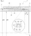
- a threaded connection 1 for steel pipe includes a tubular pin 10 and a tubular box 20.
- the pin 10 is formed from an end portion of a steel pipe 2.
- the box 20 is formed from an end portion of a coupling, and is adapted to be made up on the pin 10 as the pin 10 is inserted therein.
- the portions of the steel pipe 2 excluding the end portions may also be referred to herein as "pipe body".
- FIG. 1 shows the axis CL of the steel pipe 2, the outer diameter OD of the pipe body of the steel pipe 2, i.e. the diameter of the outer periphery, and the inner diameter ID of the pipe body, i.e. the diameter of the inner periphery.
- the steel pipe 2 of the present embodiment is a large-diameter steel pipe in which the outer diameter OD of the pipe body is larger than 240 mm.
- the box 20 includes an open end for receiving the pin 10.
- the box 20 includes a female threadform 21 provided on its inner periphery and a box seal portion 22.
- the female threadform 21 is complementary to the male threadform 11, being constituted by a thread that extends helically on the inner periphery of the box 20.
- the female threadform 21 is constituted by a wedge thread having a thread width that gradually increases from the open end toward the interior of the box 20.
- Each thread of the female threadform 21 has a dovetail-shaped cross section.
- the box seal portion 22 is composed of a taper surface located further toward the interior of the box 20 than the female threadform 21.
- the box seal portion 22 may be constituted by a cylindrical sealing surface that is shaped as an arc as seen in a cross section, or may be shaped as a combination of a straight line and an arc as seen in a cross section.
- each of the load flank 11L, 21L and stab flank 11S, 21S of each thread of the male and female threadforms 11 and 21 has a negative flank angle ⁇ .
- the flank angle ⁇ of the load flanks 11L and 21L and the flank angle ⁇ of the stab flanks 11S and 21S may be the same, or may be different.
- the threaded connection 1 for steel pipe provides a balanced combination of high torque resistance, high sealability and high shear resistance as each of the male and female threadforms 11 and 21 is constituted by a wedge thread and the male threadform 11 is constructed such that the minimum thread width of the first thread 11A, measured at its base, of the male threadform 11 is at least 3 mm and expression (1) above is satisfied.
- test specimens for FEM analysis, a plurality of test specimens (analysis models) were created with different thread profiles, and an elasto-plastic finite element analysis was conducted for each test specimen to compare their performances.
- Each test specimen was a coupling-type threaded connection having the basic construction shown in FIGS. 1 to 3 , in conjunction with steel pipes with the following parameters:
- Table 1 shows dimensions and other parameters of the threaded connections used for analysis as test specimens.
- Test specimen Thread length [mm] Thread taper [deg] TH [mm] LP [mm] SP [mm] W min [mm] Dw [mm] Expression (1) MTV [ft ⁇ lbs] Fs [N/mm] Ps [%]
- Real-pipe test #1 115.80 5.72 2.0 9.36 9.00 2.55 263.75 0.35 189685 577 -18.69 shear fracture
- test specimen #1 was created based on design rules similar to ones for conventional middle- to small-diameter pipe connections for steel pipe, while test specimens #2 to #7 were created by modifying the design of test specimen #1 with respect to load-flank pitch LP and stab-flank pitch SP.
- Test specimen #8 is based on test specimen #1, having a thread profile with a load-flank pitch LP of 11.00 mm and a stab-flank pitch SP of 10.50 mm and with an increased thread height T H .
- Test specimen #9 is based on test specimen #8, having a thread profile created by reducing the thread taper to increase the thread length.
- Test specimen length in Table 1 means the entire thread length including the perfect-thread area and imperfect-thread area.
- Thread taper means the angle twice the angle between a straight line passing through the middle, as determined along the height direction of the load flank, of each thread as seen in a cross section of the male threadform, on one hand, and the axis of the thread pipe, on the other.
Landscapes
- Engineering & Computer Science (AREA)
- Geology (AREA)
- Life Sciences & Earth Sciences (AREA)
- Mechanical Engineering (AREA)
- Mining & Mineral Resources (AREA)
- General Engineering & Computer Science (AREA)
- Physics & Mathematics (AREA)
- Environmental & Geological Engineering (AREA)
- Fluid Mechanics (AREA)
- General Life Sciences & Earth Sciences (AREA)
- Geochemistry & Mineralogy (AREA)
- Non-Disconnectible Joints And Screw-Threaded Joints (AREA)
- Mutual Connection Of Rods And Tubes (AREA)
Claims (5)
- Gewindeverbindung für Stahlrohr (1), geeignet für die Prospektion oder Produktion in Ölquellen, die Erschließung nicht-konventioneller Ressourcen wie Ölsand oder Schiefergas, die Rückgewinnung oder Speicherung von Kohlendioxid (Kohlendioxidabscheidung und -speicherung (Carbon dioxide Capture and Storage, (CCS))), für die geothermische Stromerzeugung oder in heißen Quellen, wobei die Gewindeverbindung für Stahlrohr (1) einen rohrförmigen Stift (10) umfasst, der an einer Spitze eines Stahlrohrs (2) mit einem Außendurchmesser OD von mehr als 240 mm vorgesehen ist, und ein rohrförmiges Gehäuse (20) umfasst, das so ausgelegt ist, dass es beim Einschrauben des Stifts auf dem Stift angebracht wird, wobei der Stift eine Außengewindeform (11) enthält, die mit einem konischen Gewinde an einem Außenumfang des Stifts (10) gebildet ist, das Gehäuse (20) eine Innengewindeform (21) enthält, die mit einem konischen Gewinde an einem Innenumfang des Gehäuses (20) gebildet ist, jede der Außen- und Innengewindeformen (11, 21) einen schwalbenschwanzförmigen Querschnitt aufweist und eine Steigungsflankensteilheit für die Außengewindeform (11) und die Innengewindeform (21) kleiner ist als eine Lastflankensteilheit für die Außengewindeform (11) und die Innengewindeform (21), unddadurch gekennzeichnet, dass die Außengewindeform die folgenden Ausdrücke (1) und (2) erfüllt:

 wobei in den Ausdrücken (1) und (2) OD der Außendurchmesser des Stahlrohrs, ID der Innendurchmesser des Stahlrohrs (2), DW der Durchmesser des an die Lastflanke angrenzenden Fußes am Ende der Außengewindeform näher an der Spitze, TH die Gewindehöhe der Außengewindeform und Wmin die Breite des Gewindes ist, gemessen an seiner Basis, in einem Endbereich der Außengewindeform näher an der Spitze.
 - Gewindeverbindung für Stahlrohr (1) nach Anspruch 1, wobei die Außengewindeform (11) die folgende Gleichung (3) erfüllt:

- Gewindeverbindung für Stahlrohr (1) nach Anspruch 1 oder 2, wobei die Gewindehöhe (TH) der Außengewindeform (11) nicht kleiner als 1,8 mm ist.
- Gewindeverbindung für Stahlrohr (1) nach Anspruch 1, 2 oder 3, wobei die Gewindehöhe (TH) der Außengewindeform (11) nicht größer als 2,3 mm ist.
- Gewindeverbindung für Stahlrohr (1) nach einem der Ansprüche 1 bis 4, wobei ein Kegelwinkel des Außengewindes (11) nicht größer als 5,72° ist.
Applications Claiming Priority (2)
| Application Number | Priority Date | Filing Date | Title |
|---|---|---|---|
| JP2019159375 | 2019-09-02 | ||
| PCT/JP2020/031462 WO2021044862A1 (ja) | 2019-09-02 | 2020-08-20 | 鋼管用ねじ継手 |
Publications (4)
| Publication Number | Publication Date |
|---|---|
| EP4027044A1 EP4027044A1 (de) | 2022-07-13 |
| EP4027044A4 EP4027044A4 (de) | 2022-09-07 |
| EP4027044B1 true EP4027044B1 (de) | 2025-04-09 |
| EP4027044C0 EP4027044C0 (de) | 2025-04-09 |
Family
ID=74852773
Family Applications (1)
| Application Number | Title | Priority Date | Filing Date |
|---|---|---|---|
| EP20859731.0A Active EP4027044B1 (de) | 2019-09-02 | 2020-08-20 | Gewindekupplung für ein stahlrohr |
Country Status (10)
| Country | Link |
|---|---|
| US (1) | US11719365B2 (de) |
| EP (1) | EP4027044B1 (de) |
| JP (1) | JP7185059B2 (de) |
| CN (1) | CN114174708B (de) |
| AR (1) | AR119846A1 (de) |
| AU (1) | AU2020340650B2 (de) |
| CA (1) | CA3144702C (de) |
| MX (1) | MX2021014468A (de) |
| UA (1) | UA128340C2 (de) |
| WO (1) | WO2021044862A1 (de) |
Families Citing this family (9)
| Publication number | Priority date | Publication date | Assignee | Title |
|---|---|---|---|---|
| EP3835541A1 (de) * | 2019-12-13 | 2021-06-16 | Vallourec Oil And Gas France | Gewindeverbindung, teilweise in einem selbstsichernden eingriff mit einer äusseren schulter, die einem erhöhten drehmoment standhalten kann |
| CN115362328B (zh) * | 2020-06-26 | 2025-09-05 | 日本制铁株式会社 | 钢管用螺纹接头 |
| EP3992418B1 (de) * | 2020-10-28 | 2023-08-02 | Vallourec Oil And Gas France | Selbstsichernde gewindeverbindung, teilweise in nicht sicherndem eingriff |
| EP4102025B1 (de) * | 2021-06-07 | 2023-06-07 | Vallourec Oil And Gas France | Selbstsichernde gewindeverbindung, teilweise in nicht sicherndem eingriff |
| CA3243719A1 (en) * | 2022-01-20 | 2025-06-13 | Metal One Corporation | STEEL PIPE JOINT STRUCTURE AND STEEL PIPE MACHINING METHOD |
| CN115493851A (zh) * | 2022-10-10 | 2022-12-20 | 邯郸市永年区海翔机械厂 | 用于连接分圈活门和试验台的试验夹具及其使用方法 |
| WO2025104964A1 (ja) * | 2023-11-14 | 2025-05-22 | 日本製鉄株式会社 | 鋼管用ねじ継手 |
| US20250369540A1 (en) | 2024-05-31 | 2025-12-04 | Martinrea International US Inc. | Graphene enhanced fuel hose |
| WO2026078758A1 (ja) * | 2024-10-07 | 2026-04-16 | Jfeスチール株式会社 | 鋼管用ねじ継手 |
Family Cites Families (12)
| Publication number | Priority date | Publication date | Assignee | Title |
|---|---|---|---|---|
| USRE30647E (en) | 1975-04-23 | 1981-06-16 | Hydril Company | Tubular connection |
| US4822081A (en) * | 1987-03-23 | 1989-04-18 | Xl Systems | Driveable threaded tubular connection |
| FR2820806B1 (fr) * | 2001-02-09 | 2004-02-20 | Vallourec Mannesmann Oil & Gas | Joint filete tubulaire avec face de filet bombee convexe |
| US6682101B2 (en) * | 2002-03-06 | 2004-01-27 | Beverly Watts Ramos | Wedgethread pipe connection |
| FR2939861B1 (fr) * | 2008-12-16 | 2010-12-24 | Vallourec Mannesmann Oil & Gas France | Joint tubulaire a filetage autobloquant utilise dans l'industrie du petrole |
| US10253573B2 (en) * | 2013-12-05 | 2019-04-09 | Nippon Steel & Sumitomo Metal Corporation | Threaded joint for steel pipes |
| MX376939B (es) | 2014-06-20 | 2025-03-07 | Nippon Steel Corp | Junta roscada para tubos de acero. |
| JP6417948B2 (ja) | 2015-01-13 | 2018-11-07 | 新日鐵住金株式会社 | ドリフトゲージ及びドリフト検査方法 |
| CN205558826U (zh) * | 2016-03-31 | 2016-09-07 | 西安钧力石油装备制造有限公司 | 一种变齿宽楔形管螺纹连接结构 |
| RU2702315C1 (ru) | 2016-06-08 | 2019-10-07 | Валлурек Ойл Энд Гэс Франс | Резьбовое соединение для стальной трубы |
| BR112018072626B1 (pt) * | 2016-09-16 | 2022-07-26 | Vallourec Oil And Gas France | Conexão roscada |
| EP3473798B2 (de) * | 2017-10-20 | 2025-06-18 | Vallourec Oil And Gas France | Gewindeverbindung, teilweise in einem selbsthemmenden eingriff |
-
2020
- 2020-08-20 AU AU2020340650A patent/AU2020340650B2/en active Active
- 2020-08-20 UA UAA202200301A patent/UA128340C2/uk unknown
- 2020-08-20 MX MX2021014468A patent/MX2021014468A/es unknown
- 2020-08-20 JP JP2021543693A patent/JP7185059B2/ja active Active
- 2020-08-20 CN CN202080055109.9A patent/CN114174708B/zh active Active
- 2020-08-20 CA CA3144702A patent/CA3144702C/en active Active
- 2020-08-20 EP EP20859731.0A patent/EP4027044B1/de active Active
- 2020-08-20 US US17/595,734 patent/US11719365B2/en active Active
- 2020-08-20 WO PCT/JP2020/031462 patent/WO2021044862A1/ja not_active Ceased
- 2020-08-27 AR ARP200102417A patent/AR119846A1/es active IP Right Grant
Also Published As
| Publication number | Publication date |
|---|---|
| EP4027044A1 (de) | 2022-07-13 |
| UA128340C2 (uk) | 2024-06-12 |
| WO2021044862A1 (ja) | 2021-03-11 |
| CA3144702C (en) | 2024-04-30 |
| AU2020340650A1 (en) | 2021-12-02 |
| EP4027044A4 (de) | 2022-09-07 |
| CN114174708A (zh) | 2022-03-11 |
| JPWO2021044862A1 (de) | 2021-03-11 |
| MX2021014468A (es) | 2022-01-06 |
| AR119846A1 (es) | 2022-01-12 |
| JP7185059B2 (ja) | 2022-12-06 |
| BR112021022614A2 (pt) | 2022-05-03 |
| US11719365B2 (en) | 2023-08-08 |
| CA3144702A1 (en) | 2021-03-11 |
| EP4027044C0 (de) | 2025-04-09 |
| CN114174708B (zh) | 2023-03-17 |
| AU2020340650B2 (en) | 2023-06-29 |
| US20220252188A1 (en) | 2022-08-11 |
Similar Documents
| Publication | Publication Date | Title |
|---|---|---|
| EP4027044A1 (de) | Gewindekupplung für ein stahlrohr | |
| EP3078893B1 (de) | Schraubverbindung für stahlrohre | |
| EP3205918B1 (de) | Schraubverbindung für stahlrohre | |
| EP3366968B1 (de) | Gewindeanschluss für stahlrohre | |
| US12018777B2 (en) | Threaded connection for steel pipe | |
| EP3392543B1 (de) | Schraubverbindung für stahlrohre | |
| EP3865753B1 (de) | Gewindeverbindung für stahlrohr | |
| EP4012239B1 (de) | Gewindekupplung für stahlrohr | |
| EP3708892B1 (de) | Gewindeverbindung für stahlrohre | |
| CN205638264U (zh) | 管螺纹接头 | |
| CA3145225C (en) | Threaded connection | |
| EP3854987B1 (de) | Selbstsichernde gewindeverbindung, teilweise in nicht sicherndem eingriff | |
| EP3865752A1 (de) | Gewindeverbindung für stahlrohr | |
| OA20890A (en) | Steel pipe threaded coupling. | |
| CA3169103C (en) | Threaded connection for steel pipe | |
| OA21386A (en) | Threaded joint for steel pipe. | |
| EA042334B1 (ru) | Резьбовое соединение для стальных труб | |
| BR112021022614B1 (pt) | Conexão roscada para tubo de aço | |
| OA21091A (en) | Screw-threaded joint |
Legal Events
| Date | Code | Title | Description |
|---|---|---|---|
| STAA | Information on the status of an ep patent application or granted ep patent |
Free format text: STATUS: THE INTERNATIONAL PUBLICATION HAS BEEN MADE |
|
| PUAI | Public reference made under article 153(3) epc to a published international application that has entered the european phase |
Free format text: ORIGINAL CODE: 0009012 |
|
| STAA | Information on the status of an ep patent application or granted ep patent |
Free format text: STATUS: REQUEST FOR EXAMINATION WAS MADE |
|
| 17P | Request for examination filed |
Effective date: 20211102 |
|
| AK | Designated contracting states |
Kind code of ref document: A1 Designated state(s): AL AT BE BG CH CY CZ DE DK EE ES FI FR GB GR HR HU IE IS IT LI LT LU LV MC MK MT NL NO PL PT RO RS SE SI SK SM TR |
|
| A4 | Supplementary search report drawn up and despatched |
Effective date: 20220809 |
|
| RIC1 | Information provided on ipc code assigned before grant |
Ipc: E21B 17/042 20060101ALI20220803BHEP Ipc: F16L 15/06 20060101AFI20220803BHEP |
|
| DAV | Request for validation of the european patent (deleted) | ||
| DAX | Request for extension of the european patent (deleted) | ||
| REG | Reference to a national code |
Ref country code: DE Ref legal event code: R079 Free format text: PREVIOUS MAIN CLASS: F16L0015060000 Ipc: E21B0017042000 Ref country code: DE Ref legal event code: R079 Ref document number: 602020049272 Country of ref document: DE Free format text: PREVIOUS MAIN CLASS: F16L0015060000 Ipc: E21B0017042000 |
|
| GRAP | Despatch of communication of intention to grant a patent |
Free format text: ORIGINAL CODE: EPIDOSNIGR1 |
|
| STAA | Information on the status of an ep patent application or granted ep patent |
Free format text: STATUS: GRANT OF PATENT IS INTENDED |
|
| RIC1 | Information provided on ipc code assigned before grant |
Ipc: F16L 15/06 20060101ALI20240903BHEP Ipc: F16L 15/00 20060101ALI20240903BHEP Ipc: E21B 17/042 20060101AFI20240903BHEP |
|
| INTG | Intention to grant announced |
Effective date: 20240913 |
|
| GRAJ | Information related to disapproval of communication of intention to grant by the applicant or resumption of examination proceedings by the epo deleted |
Free format text: ORIGINAL CODE: EPIDOSDIGR1 |
|
| STAA | Information on the status of an ep patent application or granted ep patent |
Free format text: STATUS: REQUEST FOR EXAMINATION WAS MADE |
|
| GRAP | Despatch of communication of intention to grant a patent |
Free format text: ORIGINAL CODE: EPIDOSNIGR1 |
|
| STAA | Information on the status of an ep patent application or granted ep patent |
Free format text: STATUS: GRANT OF PATENT IS INTENDED |
|
| INTC | Intention to grant announced (deleted) | ||
| INTG | Intention to grant announced |
Effective date: 20241126 |
|
| GRAS | Grant fee paid |
Free format text: ORIGINAL CODE: EPIDOSNIGR3 |
|
| GRAA | (expected) grant |
Free format text: ORIGINAL CODE: 0009210 |
|
| STAA | Information on the status of an ep patent application or granted ep patent |
Free format text: STATUS: THE PATENT HAS BEEN GRANTED |
|
| AK | Designated contracting states |
Kind code of ref document: B1 Designated state(s): AL AT BE BG CH CY CZ DE DK EE ES FI FR GB GR HR HU IE IS IT LI LT LU LV MC MK MT NL NO PL PT RO RS SE SI SK SM TR |
|
| REG | Reference to a national code |
Ref country code: GB Ref legal event code: FG4D |
|
| REG | Reference to a national code |
Ref country code: CH Ref legal event code: EP |
|
| REG | Reference to a national code |
Ref country code: DE Ref legal event code: R096 Ref document number: 602020049272 Country of ref document: DE |
|
| REG | Reference to a national code |
Ref country code: IE Ref legal event code: FG4D |
|
| U01 | Request for unitary effect filed |
Effective date: 20250410 |
|
| U07 | Unitary effect registered |
Designated state(s): AT BE BG DE DK EE FI FR IT LT LU LV MT NL PT RO SE SI Effective date: 20250416 |
|
| PGFP | Annual fee paid to national office [announced via postgrant information from national office to epo] |
Ref country code: GB Payment date: 20250626 Year of fee payment: 6 |
|
| U20 | Renewal fee for the european patent with unitary effect paid |
Year of fee payment: 6 Effective date: 20250709 |
|
| PG25 | Lapsed in a contracting state [announced via postgrant information from national office to epo] |
Ref country code: ES Free format text: LAPSE BECAUSE OF FAILURE TO SUBMIT A TRANSLATION OF THE DESCRIPTION OR TO PAY THE FEE WITHIN THE PRESCRIBED TIME-LIMIT Effective date: 20250409 |
|
| PG25 | Lapsed in a contracting state [announced via postgrant information from national office to epo] |
Ref country code: GR Free format text: LAPSE BECAUSE OF FAILURE TO SUBMIT A TRANSLATION OF THE DESCRIPTION OR TO PAY THE FEE WITHIN THE PRESCRIBED TIME-LIMIT Effective date: 20250710 |
|
| PGFP | Annual fee paid to national office [announced via postgrant information from national office to epo] |
Ref country code: NO Payment date: 20250808 Year of fee payment: 6 |
|
| PG25 | Lapsed in a contracting state [announced via postgrant information from national office to epo] |
Ref country code: PL Free format text: LAPSE BECAUSE OF FAILURE TO SUBMIT A TRANSLATION OF THE DESCRIPTION OR TO PAY THE FEE WITHIN THE PRESCRIBED TIME-LIMIT Effective date: 20250409 |
|
| PG25 | Lapsed in a contracting state [announced via postgrant information from national office to epo] |
Ref country code: HR Free format text: LAPSE BECAUSE OF FAILURE TO SUBMIT A TRANSLATION OF THE DESCRIPTION OR TO PAY THE FEE WITHIN THE PRESCRIBED TIME-LIMIT Effective date: 20250409 |
|
| PG25 | Lapsed in a contracting state [announced via postgrant information from national office to epo] |
Ref country code: RS Free format text: LAPSE BECAUSE OF FAILURE TO SUBMIT A TRANSLATION OF THE DESCRIPTION OR TO PAY THE FEE WITHIN THE PRESCRIBED TIME-LIMIT Effective date: 20250709 |
|
| PG25 | Lapsed in a contracting state [announced via postgrant information from national office to epo] |
Ref country code: IS Free format text: LAPSE BECAUSE OF FAILURE TO SUBMIT A TRANSLATION OF THE DESCRIPTION OR TO PAY THE FEE WITHIN THE PRESCRIBED TIME-LIMIT Effective date: 20250809 |
|
| PG25 | Lapsed in a contracting state [announced via postgrant information from national office to epo] |
Ref country code: SM Free format text: LAPSE BECAUSE OF FAILURE TO SUBMIT A TRANSLATION OF THE DESCRIPTION OR TO PAY THE FEE WITHIN THE PRESCRIBED TIME-LIMIT Effective date: 20250409 |
|
| PG25 | Lapsed in a contracting state [announced via postgrant information from national office to epo] |
Ref country code: CZ Free format text: LAPSE BECAUSE OF FAILURE TO SUBMIT A TRANSLATION OF THE DESCRIPTION OR TO PAY THE FEE WITHIN THE PRESCRIBED TIME-LIMIT Effective date: 20250409 |
|
| PG25 | Lapsed in a contracting state [announced via postgrant information from national office to epo] |
Ref country code: SK Free format text: LAPSE BECAUSE OF FAILURE TO SUBMIT A TRANSLATION OF THE DESCRIPTION OR TO PAY THE FEE WITHIN THE PRESCRIBED TIME-LIMIT Effective date: 20250409 |
|
| PLBE | No opposition filed within time limit |
Free format text: ORIGINAL CODE: 0009261 |
|
| STAA | Information on the status of an ep patent application or granted ep patent |
Free format text: STATUS: NO OPPOSITION FILED WITHIN TIME LIMIT |
|
| REG | Reference to a national code |
Ref country code: CH Ref legal event code: L10 Free format text: ST27 STATUS EVENT CODE: U-0-0-L10-L00 (AS PROVIDED BY THE NATIONAL OFFICE) Effective date: 20260218 |
|
| 26N | No opposition filed |
Effective date: 20260112 |
|
| REG | Reference to a national code |
Ref country code: CH Ref legal event code: H13 Free format text: ST27 STATUS EVENT CODE: U-0-0-H10-H13 (AS PROVIDED BY THE NATIONAL OFFICE) Effective date: 20260324 |
|
| PG25 | Lapsed in a contracting state [announced via postgrant information from national office to epo] |
Ref country code: MC Free format text: LAPSE BECAUSE OF FAILURE TO SUBMIT A TRANSLATION OF THE DESCRIPTION OR TO PAY THE FEE WITHIN THE PRESCRIBED TIME-LIMIT Effective date: 20250409 |
|
| PG25 | Lapsed in a contracting state [announced via postgrant information from national office to epo] |
Ref country code: CH Free format text: LAPSE BECAUSE OF NON-PAYMENT OF DUE FEES Effective date: 20250831 |