EP4012239B1 - Gewindekupplung für stahlrohr - Google Patents
Gewindekupplung für stahlrohr Download PDFInfo
- Publication number
- EP4012239B1 EP4012239B1 EP20852405.8A EP20852405A EP4012239B1 EP 4012239 B1 EP4012239 B1 EP 4012239B1 EP 20852405 A EP20852405 A EP 20852405A EP 4012239 B1 EP4012239 B1 EP 4012239B1
- Authority
- EP
- European Patent Office
- Prior art keywords
- section
- pin
- box
- threaded
- male
- Prior art date
- Legal status (The legal status is an assumption and is not a legal conclusion. Google has not performed a legal analysis and makes no representation as to the accuracy of the status listed.)
- Active
Links
Images

Classifications
-
- F—MECHANICAL ENGINEERING; LIGHTING; HEATING; WEAPONS; BLASTING
- F16—ENGINEERING ELEMENTS AND UNITS; GENERAL MEASURES FOR PRODUCING AND MAINTAINING EFFECTIVE FUNCTIONING OF MACHINES OR INSTALLATIONS; THERMAL INSULATION IN GENERAL
- F16L—PIPES; JOINTS OR FITTINGS FOR PIPES; SUPPORTS FOR PIPES, CABLES OR PROTECTIVE TUBING; MEANS FOR THERMAL INSULATION IN GENERAL
- F16L15/00—Screw-threaded joints; Forms of screw-threads for such joints
- F16L15/001—Screw-threaded joints; Forms of screw-threads for such joints with conical threads
- F16L15/002—Screw-threaded joints; Forms of screw-threads for such joints with conical threads with more than one threaded section
-
- E—FIXED CONSTRUCTIONS
- E21—EARTH OR ROCK DRILLING; MINING
- E21B—EARTH OR ROCK DRILLING; OBTAINING OIL, GAS, WATER, SOLUBLE OR MELTABLE MATERIALS OR A SLURRY OF MINERALS FROM WELLS
- E21B17/00—Drilling rods or pipes; Flexible drill strings; Kellies; Drill collars; Sucker rods; Cables; Casings; Tubings
- E21B17/02—Couplings; joints
- E21B17/04—Couplings; joints between rod or the like and bit or between rod and rod or the like
- E21B17/042—Threaded
- E21B17/0423—Threaded with plural threaded sections, e.g. with two-step threads
-
- E—FIXED CONSTRUCTIONS
- E21—EARTH OR ROCK DRILLING; MINING
- E21B—EARTH OR ROCK DRILLING; OBTAINING OIL, GAS, WATER, SOLUBLE OR MELTABLE MATERIALS OR A SLURRY OF MINERALS FROM WELLS
- E21B17/00—Drilling rods or pipes; Flexible drill strings; Kellies; Drill collars; Sucker rods; Cables; Casings; Tubings
- E21B17/02—Couplings; joints
- E21B17/08—Casing joints
-
- F—MECHANICAL ENGINEERING; LIGHTING; HEATING; WEAPONS; BLASTING
- F16—ENGINEERING ELEMENTS AND UNITS; GENERAL MEASURES FOR PRODUCING AND MAINTAINING EFFECTIVE FUNCTIONING OF MACHINES OR INSTALLATIONS; THERMAL INSULATION IN GENERAL
- F16L—PIPES; JOINTS OR FITTINGS FOR PIPES; SUPPORTS FOR PIPES, CABLES OR PROTECTIVE TUBING; MEANS FOR THERMAL INSULATION IN GENERAL
- F16L15/00—Screw-threaded joints; Forms of screw-threads for such joints
- F16L15/04—Screw-threaded joints; Forms of screw-threads for such joints with additional sealings
-
- F—MECHANICAL ENGINEERING; LIGHTING; HEATING; WEAPONS; BLASTING
- F16—ENGINEERING ELEMENTS AND UNITS; GENERAL MEASURES FOR PRODUCING AND MAINTAINING EFFECTIVE FUNCTIONING OF MACHINES OR INSTALLATIONS; THERMAL INSULATION IN GENERAL
- F16L—PIPES; JOINTS OR FITTINGS FOR PIPES; SUPPORTS FOR PIPES, CABLES OR PROTECTIVE TUBING; MEANS FOR THERMAL INSULATION IN GENERAL
- F16L15/00—Screw-threaded joints; Forms of screw-threads for such joints
- F16L15/001—Screw-threaded joints; Forms of screw-threads for such joints with conical threads
- F16L15/004—Screw-threaded joints; Forms of screw-threads for such joints with conical threads with axial sealings having at least one plastically deformable sealing surface
-
- F—MECHANICAL ENGINEERING; LIGHTING; HEATING; WEAPONS; BLASTING
- F16—ENGINEERING ELEMENTS AND UNITS; GENERAL MEASURES FOR PRODUCING AND MAINTAINING EFFECTIVE FUNCTIONING OF MACHINES OR INSTALLATIONS; THERMAL INSULATION IN GENERAL
- F16L—PIPES; JOINTS OR FITTINGS FOR PIPES; SUPPORTS FOR PIPES, CABLES OR PROTECTIVE TUBING; MEANS FOR THERMAL INSULATION IN GENERAL
- F16L15/00—Screw-threaded joints; Forms of screw-threads for such joints
- F16L15/06—Screw-threaded joints; Forms of screw-threads for such joints characterised by the shape of the screw-thread
Definitions
- the present disclosure relates to a threaded connection used to connect steel pipes.
- oil wells natural-gas wells etc.
- underground resources are mined using casing that forms a plurality of well walls, which form layers, and tubing positioned within the casing to produce oil or gas.
- casing and tubing are constructed by connecting large numbers of steel pipes in series, where threaded connections are used to connect the pipes.
- Steel pipes used in oil wells are also referred to as oil-well pipes.
- Threaded connections are generally categorized as integral type and coupling type.
- An integral connection directly connects oil-well pipes. Specifically, a female thread is provided on one end of an oil-well pipe, while a male thread is provided on the other end, and the male thread of one oil-well pipe is screwed into the female thread of another oil-well pipe such that the oil-well pipes are connected.
- a coupling-type connection connects oil-well pipes using a tubular coupling. Specifically, a female thread is provided on each end of the coupling, while a male thread is provided on each end of each oil-well pipe. Then, one male thread of one oil-well pipe is screwed into one female thread of the coupling and one male thread of another oil-well pipe is screwed into the other female thread of the coupling such that the oil-well pipes are connected. That is, a coupling-type connection connects a pair of pipes, one of which is an oil-well pipe and the other one is a coupling.
- An end portion of an oil-well pipe on which a male thread is provided includes an element to be inserted into a female thread provided on an oil-well pipe or a coupling, and thus is usually referred to as "pin”.
- An end portion of an oil-well pipe or coupling on which a female thread is provided includes an element for receiving a male thread provided on an oil-well pipe, and thus is referred to as "box”.
- Thick-wall connections and slim connections with tight size restrictions are often designed to include intermediate shoulder surfaces and an intermediate seal in the middle of the connection as determined along the axial direction and a two-step thread system with male and female threads located forward of and rearward of the intermediate shoulders/seal, as disclosed by Japanese Patent No. 5908905 (Patent Document 1), WO 2017/104282 (Patent Document 2) and WO 2015/194160 (Patent Document 3).
- the intermediate seal is mainly intended to ensure sealability against the external pressure.
- a threaded connection thus designed has critical cross sections (PICCS and BICCS) in the middle of the connection, as disclosed by Patent Document 1.
- a critical cross section is a cross section of a connection with a minimum area for bearing a tensile load when the connection is made up. When an excessive tensile load is applied, there is a high possibility that the connection breaks at a critical cross section.
- the critical cross section is the cross section of the box along the thread root of the female thread located at that one of the ends of engagement between the male and female threads when the connection is made up which is closer to the tip of the male thread.
- the ratio of the critical cross-sectional area (CCSA) to the cross-sectional area A of the pipe body of the oil-well pipe, CCSA/A is known as connection efficiency, and is widely used as an indicator for the tensile strength of a connection relative to the tensile strength of the body of an oil-well pipe.
- a coupling-type threaded connection is usually designed such that the critical cross-sectional area CCSA of the coupling is larger than the cross-sectional area A of the pipe body of the oil-well pipe and smaller than 110 % of the cross-sectional area A of the pipe body.
- ICCS intermediate critical cross section
- PICCSA Pin Intermediate Critical Cross-Sectional Area
- BICCSA Box Intermediate Critical Cross-Sectional Area
- sealability varies depending on not only the total area of the PICCS and BICCS, but also on the distribution of area among the PICCS and BICCS.
- Patent Document 1 discloses a threaded connection in which the shoulder area is maximized to provide increased torque resistance and, at the same time, the area of the CCS is kept within ⁇ 5 % relative to the total area of the PICCS and BICCS to maintain balance between the efficiencies of the four critical cross sections to maximize the efficiency of the connection and provide a certain axial performance of the connection.
- Patent Document 2 discloses providing an appropriate amount of interference between the intermediate shoulder surfaces of the pin and box to ensure sealability and prevent crevice corrosion.
- Patent Document 3 discloses a pin including a nose immediately extending from the inner sealing surface and located between the inner shoulder surface on the pin tip and the inner sealing surface to ensure that the elastic recovery of the nose amplifies the contact pressure between the inner sealing surfaces, thereby providing high sealability mainly against the internal pressure.
- Patent Documents 1 to 3 discloses effects of the ratio between the areas of the PICCS and BICCS on the sealability of the threaded connection.
- An object of the present disclosure is to ensure good sealability in a threaded connection for steel pipe of a two-step thread construction including an intermediate seal and intermediate shoulders.
- the threaded connection for steel pipe is a threaded connection for steel pipe including a tubular pin and a tubular box, the pin and the box being made up as the pin is screwed into the box.
- the pin may include, in order from a tip of the pin toward a base of the pin: a first male-threaded section; an intermediate seal section; and a second male-threaded section.
- the pin may further include an intermediate shoulder surface provided between the first male-threaded section and the intermediate seal section of the pin to face the tip.
- the box may include, in order from an interior of the box onward: a first female-threaded section adapted such that the first male-threaded section of the pin is fitted therein when the connection is made up; an intermediate seal section adapted such that the intermediate seal section of the pin is fitted thereto when the connection is made up; and a second female-threaded section adapted such that the second male-threaded section of the pin is fitted therein when the connection is made up.
- the box may further include an intermediate shoulder surface provided between the first female-threaded section and the intermediate seal section of the box. The intermediate shoulder surface of the box faces the intermediate shoulder surface of the pin and these shoulder surfaces are facing in an axial direction of the threaded connection.
- the pin may have a pin intermediate critical cross section located near an end of the first male-threaded section that is located closer to a base (i.e. the end opposite to the end associated with the tip).
- the box may have a box critical cross section located near an end of the first female-threaded section that is located further toward the interior; and a box intermediate critical cross section located near an end of the second female-threaded section that is located further toward the interior.
- the pin and the box satisfy the following relationships: PICCSA + BICCSA > BCCSA , and 0.70 ⁇ PICCSA/BICCSA ⁇ 0 .95 , where PICCSA is the area of the pin intermediate critical cross section found when the pin and the box are not made up, BICCSA is the area of the box intermediate critical cross section found when the pin and the box are not made up, and BCCSA is the area of the box critical cross section found when the pin and the box are not made up.
- the present disclosure ensures good sealability in a threaded connection for steel pipe of a two-step thread construction including an intermediate seal and intermediate shoulders.
- the threaded connection for steel pipe includes a tubular pin and a tubular box.
- the pin and box are made up as the pin is screwed into the box.
- the pin may be provided on an end of a steel pipe such as an oil-well pipe.
- the box may be provided on an end of a coupling or an end of another steel pipe.
- the pin may include, in order from its tip onward, a nose section, an inner seal section, an inner male-threaded section, an intermediate shoulder section, an intermediate seal section, and an outer male-threaded section.
- a nose section an inner seal section
- an inner male-threaded section an intermediate shoulder section
- an intermediate seal section an intermediate seal section
- an outer male-threaded section an outer male-threaded section.
- the tip surface of the pin forms an inner shoulder surface. If the nose section is present, a tip surface of the nose section forms the inner shoulder surface. In implementations where such a nose section is absent and the tip portion of the pin is constituted by the inner seal section, the tip surface of the inner seal section forms the inner shoulder surface.
- the tip surface of the inner male-threaded section or the tip surface of another portion extending from the inner male-threaded section further in the direction of the tip may form the inner shoulder surface.
- the inner shoulder surface of the pin faces in the axial direction of the tip.
- the inner male-threaded section is provided between the inner seal section and intermediate shoulder section.
- the inner male-threaded section may have an outer periphery that gradually decreases in diameter toward the tip.
- a tapered thread that gradually decreases in diameter toward the tip may be provided on the outer periphery of the inner male-threaded section.
- the intermediate shoulder section is provided between the inner male-threaded section and intermediate seal section.
- the intermediate shoulder section may include an intermediate shoulder surface that is perpendicular to the axial direction of the pin or is tapered in shape.
- the intermediate shoulder surface may face in the axial direction of the tip.
- the intermediate seal section is provided between the intermediate shoulder section and outer male-threaded section.
- the outer male-threaded section may include an outer periphery that gradually decreases in diameter toward the tip and in which the outer diameter of the end closer to the tip is larger than the outer diameter of the end of the inner male-threaded section closer to the base.
- a tapered thread that gradually decreases in diameter toward the tip may be provided on the outer periphery of the outer male-threaded section.
- the box may include, in order from its interior onward, a recess section corresponding to the nose section of the pin, an inner seal section corresponding to the inner seal section of the pin, an inner female-threaded section corresponding to the inner male-threaded section of the pin, an intermediate shoulder section corresponding to the intermediate shoulder section of the pin, an intermediate seal section corresponding to the intermediate seal section of the pin, and an outer female-threaded section corresponding to the outer male-threaded section of the pin.
- the recess section may be constructed in such a way that the nose section may be inserted therein when the connection is made up and a clearance is formed between the nose and recess sections. In this case, the interior end surface of the recess section may form the inner shoulder surface. In implementations where the pin does not include a nose section, it is preferable that such a recess section be absent. Further, in implementations where the pin includes no inner seal section, it is preferable that the box includes no inner seal section, either.
- the inner female-threaded section is provided between the inner seal section and intermediate shoulder section.
- the inner female-threaded section may have a construction complementary to that of the inner male-threaded section of the pin, and have an inner periphery that gradually decreases in diameter toward the interior of the box.
- a tapered thread that gradually decreases in diameter toward the interior of the box may be provided on the inner periphery of the inner female-threaded section.
- the intermediate shoulder section is provided between the inner female-threaded section and intermediate seal section.
- the intermediate shoulder section may include an intermediate shoulder surface that is perpendicular to the axial direction of the box or is conical in shape. This intermediate shoulder surface faces the intermediate shoulder surface of the pin, and these surfaces are facing in the axial direction of the threaded connection.
- the intermediate seal section is provided between the intermediate shoulder section and outer female-threaded section.
- the outer female-threaded section may have a construction complementary to that of the outer male-threaded section of the pin and gradually decrease in diameter toward the interior of the box, and have an inner periphery in which the outer diameter of the end located further toward the interior has a larger outer diameter than the end of the inner female-threaded section located further toward the exterior.
- a tapered thread that gradually decreases in diameter toward the interior of the box may be provided on the inner periphery of the outer female-threaded section.
- connection When the connection is made up, the nose section of the pin is inserted into the recess section of the box.
- the inner seal section of the pin When the connection is made up, the inner seal section of the pin is fitted into the inner seal section of the box by interference fit.
- the inner male-threaded section of the pin is screwingly fitted into the inner female-threaded section of the box.
- the intermediate shoulder surface of the intermediate shoulder section of the pin faces the intermediate shoulder surface of the intermediate shoulder section of the box, and these surfaces are facing in the axial direction.
- the intermediate shoulder surface of the intermediate shoulder of the pin is in contact with the intermediate shoulder surface of the intermediate shoulder of the box.
- the intermediate seal section of the pin is fitted to the intermediate seal section of the box by interference fit.
- the outer male-threaded section of the pin is scewingly fitted into the outer female-threaded section of the box.
- the inner shoulder surface of the pin is in contact with the inner shoulder surface of the box.
- the pin has a pin intermediate critical cross section located near the end of the tapered inner male-threaded section with a larger diameter.
- the position of the pin intermediate critical cross section is the one near the end of the inner male-threaded section with a larger diameter that has the smallest cross-sectional area.
- the pin intermediate critical cross section is that cross section of the pin on which the load flanks of the inner male- and female-threaded sections come out of contact when the connection is made up.
- the box has a box critical cross section located near the end of the tapered inner female-threaded section with a smaller diameter (i.e. further toward the interior of the box) and a box intermediate critical cross section located near the end of the tapered outer female-threaded section with a smaller diameter.
- the position of the box critical cross section is the one near the end of the inner female-threaded section with a smaller diameter which has the smallest cross-sectional area.
- the box critical cross section is that cross section of the box on which the load flanks of the inner male- and female-threaded sections come out of contact when the connection is made up.
- the position of the box intermediate critical cross section is the one near the end of the outer female-threaded section with a smaller diameter which has the smallest cross-sectional area.
- the box intermediate critical cross section is that cross section of the box on which the load flanks of the outer male- and female-threaded sections come out of contact when the connection is made up.
- the pin and box satisfy the following relationships: PICCSA + BICCSA > BCCSA , and 0.70 ⁇ PICCSA/BICCSA ⁇ 0 .95 , where PICCSA is the area of the pin intermediate critical cross section found when the pin and box are not made up, BICCSA is the area of the box intermediate critical cross section when the pin and box are not made up, and BCCSA is the area of the box critical cross section found when the pin and box are not made up.
- the various critical cross sections do not include cross sections of the threads themselves of the various taper-threaded sections, and the area of a critical cross section is defined as the cross-sectional area of the pin or box as measured at a position outside the threads in the perfect and imperfect thread areas of a taper-threaded section.
- the inner periphery of the pin may have an inner diameter that is substantially constant from the nose section to the inner seal section, inner male-threaded section, intermediate shoulder, intermediate seal section and up to the outer male-threaded section.
- Each of the inner seal section and nose may have an inner periphery that gradually decreases in diameter toward the tip.
- the outer periphery of the box may have an outer diameter that is substantially constant from the inner seal section to the inner female-threaded section, intermediate shoulder, intermediate seal section and up to the outer female-threaded section.
- PICCSA/BICCSA is more preferably not less than 0.73, and yet more preferably not less than 0.75.
- PICCSA/BICCSA is more preferably not more than 0.91, and yet more preferably not more than 0.90.
- the axial distance between the pin intermediate critical cross section and intermediate seal of the pin is larger than the axial distance between the box intermediate critical cross section and intermediate seal section of the box. This will reduce the amount of deformation due to the diameter reduction of the intermediate seal section of the box caused by an external pressure acting thereon, which is expected to improve the sealability of the intermediate seal against the external pressure.
- the pin is provided on an end of the steel pipe, and the box is provided on the coupling.
- the steel pipe includes a pipe body and the pin extends from the end of the pipe body in the axial direction.
- Pipe body means pipe portions that are not located in the box upon insertion when the connection is made up.
- the box critical cross-sectional area of the coupling, BCCSA be larger than the cross-sectional area of the pipe body of the steel pipe, A. This will provide a tensile strength of the threaded connection equal to or larger than the tensile strength of the steel pipe.
- the present invention may be suitably implemented as a threaded joint for steel pipes of which the pipe body has a thickness not thinner than 20mm.
- that the thickness is not thinner than 20mm means that the minimum thickness of the pipe body is not thinner than 20mm.
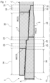
- a threaded connection for steel pipe 1 is a coupling-type threaded connection that includes a tubular pin 2 and a tubular box 3 adapted to be made up on the pin 2 as the pin 2 is screwed therein.
- the pin 2 is provided on an end of an oil-well pipe T, while the box 3 is provided on an end of a coupling C.
- the pin 2 extends in the axial direction from an end of the pipe body of the oil-well pipe T to the tip.
- the pin 2 includes a nose section 21 (hereinafter referred to as "the nose"), an inner seal section 22, a tapered inner male-threaded section 23, an intermediate shoulder section 24, an intermediate seal section 25, and a tapered outer male-threaded section 26.
- the nose a nose section 21
- an inner seal section 22 a tapered inner male-threaded section 23
- an intermediate shoulder section 24 an intermediate seal section
- a tapered outer male-threaded section 26 is tubular or annular in shape.
- the inner seal section 22 is located closer to the tip than the inner male-threaded section 23.
- the inner seal section 22 is located between the nose 21 and inner male-threaded section 23.
- On the outer periphery of the inner seal section 22 is provided the inner sealing surface, which decreases in diameter toward the tip.
- the shape of a longitudinal cross section of this sealing surface may be a straight line or an arc, or a combination of a straight line and an arc.
- the inner male-threaded section 23 is provided between the inner seal section 22 and intermediate shoulder section 24. On the outer periphery of the inner male-threaded section 23 is provided a tapered thread that gradually decreases in diameter toward the tip.
- the intermediate shoulder section 24 is provided between the inner male-threaded section 23 and intermediate seal section 25 and, in the construction shown in FIG. 1 , located near the middle of the pin 2 as determined along the axial direction.
- the intermediate shoulder section 24 includes an intermediate shoulder surface substantially perpendicular to the pipe axis CL.
- the intermediate shoulder surface is constituted by a stepped portion provided on the outer periphery of the pin 2 and located between the inner male-threaded section 23 and intermediate seal section 25.
- the intermediate shoulder surface faces toward the tip.
- the intermediate shoulder surface may be slightly inclined such that the outer or inner periphery is located further toward the tip of the pin 2.
- the intermediate seal section 25 is provided between the intermediate shoulder section 24 and outer male-threaded section 26.
- On the outer periphery of the intermediate seal section 25 is provided an intermediate sealing surface that decreases in diameter toward the tip.
- the shape of a longitudinal cross section of this sealing surface may be a straight line or an arc, or a combination of a straight line and an arc.
- outer male-threaded section 26 On the outer periphery of the outer male-threaded section 26 is provided a tapered thread that gradually decreases in diameter toward the tip.
- the outer and inner diameters of the end of the outer male-threaded section 26 closer to the basement are substantially equal to the outer and inner diameters of the pipe body of the oil-well pipe T.
- the box 3 includes a recess section 31 (hereinafter referred to as "the recess") corresponding to the nose 21, an inner seal section 32 corresponding to the inner seal section 22, a tapered inner female-threaded section 33 corresponding to the inner male-threaded section 23, an intermediate shoulder section 34 corresponding to the intermediate shoulder section 24, an intermediate seal section 35 corresponding to the intermediate seal section 25, and an outer female-threaded section 36 corresponding to the outer male-threaded section 26.
- Each of the sections 31 to 35 is tubular or annular in shape.
- the recess 31 is located further toward the interior than the inner seal section 22. That is, the recess 31 is located in the most interior region in the box 3.
- the nose 21 of the pin 2 is inserted into the recess 31.
- the interior end surface of the recess 31 functions as an inner shoulder surface to be contacted by the inner shoulder surface of the pin 2.
- the inner shoulder surface of the pin 2 and the inner shoulder surface of the box 3 may not be in contact with each other and a clearance may be formed therebetween.
- the inner seal section 32 is located further toward the interior than the inner female-threaded section 33.
- the inner seal section 32 is located between the recess 31 and inner female-threaded section 33.
- On the inner periphery of the inner seal section 32 is provided an inner sealing surface that decreases in diameter toward the interior of the box (in other words, toward the tip of the pin).
- the shape of a longitudinal cross section of this sealing surface may be a straight line or an arc, or a combination of a straight line and an arc.
- the inner female-threaded section 33 is provided between the inner seal section 32 and intermediate shoulder section 34. On the inner periphery of the inner female-threaded section 33 is provided a tapered thread that gradually decreases in diameter toward the interior of the box.
- the intermediate shoulder section 34 is provided between the inner female-threaded section 33 and intermediate seal section 35 and, in the construction shown in FIG. 1 , located near the middle of the box 3 as determined along the axial direction. When the connection is made up, the intermediate shoulder section 34 is located closer to the tip than the intermediate shoulder section 24 of the pin 2.
- the intermediate shoulder section 34 includes an intermediate shoulder surface substantially perpendicular to the pipe axis CL. This intermediate shoulder surface is constituted by a stepped portion provided on the inner periphery of the box 3 and located between the inner female-threaded section 33 and intermediate seal section 35. The intermediate shoulder surface faces the intermediate shoulder surface of the pin 2 and these surfaces are facing in the axial direction.
- the axial length of the intermediate shoulder section 24 of the pin 2 is larger than the axial length of the intermediate shoulder section 34 of the box 3.
- the axial length of the intermediate shoulder section 34 of the box 3 may be larger than the axial length of the intermediate shoulder 24 of the pin 2.
- the intermediate seal section 35 is provided between the intermediate shoulder section 34 and outer female-threaded section 36.
- On the inner periphery of the intermediate seal section 35 is provided an intermediate sealing surface that decreases in diameter toward the interior of the box.
- the shape of a longitudinal cross section of this sealing surface may be a straight line or an arc, or a combination of a straight line and an arc.
- a tapered thread that gradually decreases in diameter toward the interior of the box.
- the inner female-threaded section 33 is constructed such that the inner male-threaded section 23 can be screwed therein and, when the connection is made up, they are in tight fitting contact with each other by interference fit.
- the outer female-threaded section 36 is constructed such that the outer male-threaded section 26 can be screwed therein and, when the connection is made up, they are in tight fitting contact with each other by interference fit. As the pin 2 is screwed in, the inner seal sections 22 and 32 come into contact with each other and, when the connection is made up, they are in tight fitting contact with each other by interference fit.
- the intermediate seal sections 25 and 35 also come into contact with each other and, when the connection is made up, they are in tight fitting contact with each other by interference fit.
- the inner sealing surfaces of the inner seal sections 22 and 32 as well as the intermediate sealing surfaces of the intermediate seal sections 25 and 35 are strongly pressed together to form metal seals.
- the tight fitting contact between the inner seal sections 22 and 32 ensures sealability mainly against the internal pressure.
- the tight fitting contact between the intermediate seal sections 25 and 35 ensures sealability mainly against the external pressure.
- connection may be constructed such that one of the tip shoulder surface and intermediate shoulder surface of the pin 2 does not contact the box 3.
- the pin 2 further includes a pin intermediate critical cross section (PICCS) located near that end of the tapered inner male-threaded section 23 which has a larger diameter (i.e. closer to the basement).
- the box 3 further includes a box critical cross section (BCCS) located near that end of the tapered inner female-threaded section 33 which has a smaller diameter (i.e. closer to the interior of the box) and a box intermediate critical cross section (BICCS) located near that end of the tapered outer female-threaded section 36 which has a smaller diameter (i.e. closer to the interior of the box).
- the pin 2 and box 3 are constructed such that the areas of these critical cross sections satisfy the following expressions.
- PICCSA + BICCSA > BCCSA and 0 .70 ⁇ PICCSA/BICCSA ⁇ 0.95 .
- PICCSA is the area of the PICCS
- BICCSA is the area of the BICCS
- BCCSA is the area of the BCCS.
- the axial distance between the pin intermediate critical cross section (PICCS) and intermediate seal section 25 of the pin 2 is larger than the axial distance between the box intermediate critical cross section (BICCS) and intermediate seal section 35 of the box 3. More preferably, the axial distance between the pin intermediate critical cross section (PICCS) and intermediate seal section 25 may be larger than the axial distance between the intermediate shoulder surface and intermediate seal section 25. In implementations where the intermediate sealing surfaces of the intermediate seal sections 25 and 35 come into surface contact, the position on each of these surfaces used in measuring these axial distances may be the midpoint of the range of surface contact as determined along the axial direction.
- box critical cross section BCCSA of the coupling C is larger than the cross-sectional area A of the pipe body of the oil-well pipe T.
- the present embodiment ensures good sealability in a threaded connection for steel pipe of a two-step thread construction including an intermediate seal and intermediate shoulders. The reasons therefor will be discussed in detail below.
- the pin intermediate critical cross section PICCSA is smaller than the box intermediate critical cross section BICCSA, the presence of the intermediate seal section 25 of the pin 2 between the intermediate shoulder section 24 and outer male-threaded section 26 ensures that the intermediate seal section 25 has a large cross-sectional area, thereby reducing the deformation due to the diameter reduction of the intermediate seal section 25 occurring when a large external pressure is applied.
- the ratio of the area of the pin intermediate critical cross section (PICCS) to the area of the box intermediate critical cross section (BICCS), PICCSA/BICCSA is not lower than 0.70 and not higher than 0.95, the amount of extension of portions of the pin 2 at and near the pin intermediate critical cross section occurring when a tensile load is applied is substantially equal to the amount of extension of portions of the box 3 at and near the box intermediate critical cross section, thereby preventing the intermediate sealing surface of the pin 2 and the intermediate sealing surface of the box 3 from being displaced from each other as determined along the axial direction, and preventing bending deformation of portions at and near the sealing surfaces to maintain the effective amount of seal interference, preventing a reduction in sealability.
- the present disclosure may not only be applied to coupling-type threaded connections, but also to integral threaded connections. Further, no nose may be provided on the tip of the pin. Further, while FIG. 1 shows an embodiment in which the tapered threads of the various threaded sections are trapezoidal threads, the tapered threads may be API round threads, API buttress threads or wedge threads.
- the present disclosure is not limited to the above-illustrated embodiment. The invention is defined by the claims.
- test specimens For a coupling-type threaded connection for oil-well pipe, a plurality of test specimens (analysis models) were created with different values of the ratio of the areas of the PICCS and BICCS, i.e. PICCSA/BICCSA, and an elasto-plastic finite element analysis was conducted for each test specimen to compare their performances.
- Each test specimen was a coupling-type threaded connection having the basic construction shown in FIG. 1 .
- the common test conditions are provided below.
- each test specimen was modeled in such a way that the material was an elasto-plastic object with isotropic hardening; the elastic coefficient was 210 [GPa]; and the yield strength was 110 [ksi] (758.3 [MPa]) for 0.2 % proof stress.
- Test specimens #1 to #8 are examples according to the present disclosure, while test specimens #9 and #10 are comparative examples.
- Test specimens #2 to #5 and #10 share the same box with test specimen #1 but have different pin dimensions.
- Test specimens #6 to #9 share the same pin with test specimen #1 but have different box dimensions.
- FIG. 2 graphs the relationship between the ratio of the pin intermediate critical cross-sectional area to the box intermediate critical cross-sectional area, on one hand, and sealability, on the other.
- FIG. 3 graphs the relationship between the sum of the ratios of the intermediate critical cross-sectional areas of the pin and box, on one hand, and sealability, on the other.
- PICCSA+BICCSA was smaller than the box critical cross-sectional area and PICCSA+BICCSA was smaller than 0.7, which is why the amount of deformation at and near the intermediate seal was large and good sealability was not obtained.
Landscapes
- Engineering & Computer Science (AREA)
- Mechanical Engineering (AREA)
- Life Sciences & Earth Sciences (AREA)
- Geology (AREA)
- Mining & Mineral Resources (AREA)
- General Engineering & Computer Science (AREA)
- Physics & Mathematics (AREA)
- Environmental & Geological Engineering (AREA)
- Fluid Mechanics (AREA)
- General Life Sciences & Earth Sciences (AREA)
- Geochemistry & Mineralogy (AREA)
- Non-Disconnectible Joints And Screw-Threaded Joints (AREA)
Claims (9)
- Gewindeverbindung (1) für Stahlrohre, umfassend einen rohrförmigen Stift (2) und ein rohrförmiges Gehäuse (3), wobei der Stift (2) und das Gehäuse (3) zusammengefügt werden, wenn der Stift (2) in das Gehäuse (3) eingeschraubt wird, wobei:der Stift (2) in einer Reihenfolge von einer Spitze des Stifts (2) zu einer Basis des Stifts (2) beinhaltet: einen ersten Bereich (23) mit Außengewinde; einen Zwischendichtungsbereich (25); und einen zweiten Bereich (26) mit Außengewinde,der Stift (2) ferner eine Zwischenschulteroberfläche beinhaltet, die zwischen dem ersten Bereich (23) mit Außengewinde und dem Zwischendichtungsbereich (25) des Stifts (2) bereitgestellt ist, um der Spitze zugewandt zu sein;das Gehäuse (3) in der Reihenfolge von einem Innenraum des Gehäuses (3) vorwärts beinhaltet: einen ersten Bereich (33) mit Innengewinde, der angepasst ist, sodass der erste Bereich (23) mit Außengewinde des Stifts (2) bei der Herstellung der Verbindung darin eingepasst wird; einen Zwischendichtungsbereich (35) der angepasst ist, sodass der Zwischendichtungsbereich (25) des Stifts (2) bei der Herstellung der Verbindung darin eingepasst wird; und einen zweiten Abschnitt (36) mit Innengewinde, der angepasst ist, sodass der Bereich (26) mit Außengewinde des Stifts (2) bei der Herstellung der Verbindung darin eingepasst wird,das Gehäuse (3) ferner eine Zwischenschulteroberfläche beinhaltet, die zwischen dem ersten Bereich (33) mit Innengewinde und dem Zwischendichtungsbereich (35) des Gehäuses (3) bereitgestellt ist, wobei die Zwischenschulteroberfläche des Gehäuses (3) der Zwischenschulteroberfläche des Stifts (2) zugewandt ist, wobei diese Schulteroberflächen in eine axiale Richtung der Gewindeverbindung (1) gewandt sind;der Stift (2) einen kritischen Zwischenquerschnitt des Stifts (PICCS) aufweist, der sich in der Nähe eines Endes des ersten Bereichs (23) mit Außengewinde befindet, der sich näher an einer Basis befindet, unddas Gehäuse (3) einen kritischen Gehäusequerschnitt (BCCS), der sich in der Nähe eines Endes des ersten Bereichs (33) mit Innengewinde befindet, der sich weiter zu dem Innenraum hin befindet, und einen kritischen Zwischenquerschnitt des Gehäuses (BICCS) aufweist, der sich näher an einem Ende des zweiten Bereichs (36) befindet, der sich weiter zu dem Innenraum hin befindet,dadurch gekennzeichnet, dassder Stift (2) und das Gehäuse (3) die folgenden Beziehungen erfüllen:

 wobei PICCSA die Fläche des kritischen Zwischenquerschnitts des Stifts (PICCS) ist, die vorgefunden wird, wenn der Stift (2) und das Gehäuse (3) nicht zusammengesetzt sind, BICCSA die Fläche des kritischen Zwischenquerschnitts des Gehäuses (BICCS) ist, die vorgefunden wird, wenn der Stift (2) und das Gehäuse (3) nicht zusammengesetzt sind, und BCCSA die Fläche des kritischen Gehäusequerschnitts (BCCS) ist, die vorgefunden wird, wenn der Stift (2) und das Gehäuse (3) nicht zusammengesetzt sind.
 - Gewindeverbindung für Stahlrohre nach Anspruch 1, wobei PICCSA/BICCSA nicht kleiner als 0,73 ist.
- Gewindeverbindung für Stahlrohre nach Anspruch 1 oder 2, wobei PICCSA/BICCSA nicht größer als 0,91 ist.
- Gewindeverbindung für Stahlrohre nach einem der Ansprüche 1 bis 3, wobei der Stift (2) ferner einen inneren Dichtungsbereich (22) beinhaltet, der sich näher an der Spitze befindet als der erste Bereich (24) mit Außengewinde, das Gehäuse (3) ferner einen inneren Dichtungsbereich (32) beinhaltet, der sich weiter zu dem Innenraum hin befindet als der erste Bereich (33) mit Innengewinde, und der innere Dichtungsbereich (22) des Stifts (2) in den inneren Bereich (32) des Gehäuses (3) eingepasst wird, wenn die Verbindung hergestellt wird.
- Gewindeverbindung für Stahlrohre nach Anspruch 4, wobei der Stift (2) ferner einen Nasenbereich (21) beinhaltet, der sich näher an der Spitze befindet als der innere Dichtungsbereich (22) des Stifts (2), das Gehäuse (3) ferner einen Vertiefungsbereich (31) beinhaltet, der sich weiter zu dem Innenraum hin befindet als der Bereich (32) mit Innengewinde des Gehäuses (3), und der Nasenbereich (21) in den Vertiefungsbereich (31) eingesetzt wird, wenn die Verbindung hergestellt wird.
- Gewindeverbindung für Stahlrohre nach einem der Ansprüche 1 bis 5, wobei der Stift (2) ferner eine innere Schulteroberfläche beinhaltet, die von einer Spitzenoberfläche des Stifts (2) ausgebildet wird, und das Gehäuse (3) ferner eine innere Schulteroberfläche beinhaltet, die positioniert ist, um der inneren Schulteroberfläche des Stifts (2) zugewandt zu sein, wobei diese Oberflächen in die axiale Richtung gewandt sind.
- Gewindeverbindung für Stahlrohr nach einem der Ansprüche 1 bis 6, wobei sich der Stift (2) von einem Ende eines Rohrkörpers des Stahlrohrs (T) in der axialen Richtung zu der Spitze erstreckt, und das Gehäuse (3) an einer Kopplung (C) bereitgestellt ist.
- Gewindeverbindung für Stahlrohre nach Anspruch 7, wobei die Fläche des kritischen Gehäusequerschnitts BCCSA der Kopplung (C) größer ist als eine Querschnittsfläche A des Rohrkörpers des Stahlrohrs (T).
- Gewindeverbindung für Stahlrohre nach Anspruch 7 oder 8, wobei der Rohrkörper eine Dicke von nicht weniger als 20 mm aufweist.
Applications Claiming Priority (2)
| Application Number | Priority Date | Filing Date | Title |
|---|---|---|---|
| JP2019147926 | 2019-08-09 | ||
| PCT/JP2020/030407 WO2021029370A1 (ja) | 2019-08-09 | 2020-08-07 | 鋼管用ねじ継手 |
Publications (4)
| Publication Number | Publication Date |
|---|---|
| EP4012239A1 EP4012239A1 (de) | 2022-06-15 |
| EP4012239A4 EP4012239A4 (de) | 2022-08-03 |
| EP4012239B1 true EP4012239B1 (de) | 2024-10-23 |
| EP4012239C0 EP4012239C0 (de) | 2024-10-23 |
Family
ID=74570295
Family Applications (1)
| Application Number | Title | Priority Date | Filing Date |
|---|---|---|---|
| EP20852405.8A Active EP4012239B1 (de) | 2019-08-09 | 2020-08-07 | Gewindekupplung für stahlrohr |
Country Status (9)
| Country | Link |
|---|---|
| US (1) | US11753878B2 (de) |
| EP (1) | EP4012239B1 (de) |
| JP (1) | JP7182010B2 (de) |
| CN (1) | CN114026309B (de) |
| AU (1) | AU2020327779B2 (de) |
| CA (1) | CA3140090C (de) |
| MX (1) | MX2021015733A (de) |
| UA (1) | UA128272C2 (de) |
| WO (1) | WO2021029370A1 (de) |
Families Citing this family (7)
| Publication number | Priority date | Publication date | Assignee | Title |
|---|---|---|---|---|
| CA3140090C (en) * | 2019-08-09 | 2023-06-27 | Keita INOSE | Threaded connection for steel pipe |
| CN114270012B (zh) | 2019-09-24 | 2024-07-16 | 日本制铁株式会社 | 螺纹接头 |
| CA3113361A1 (en) * | 2020-03-26 | 2021-09-26 | NejiLaw inc. | Oil well pipe connection structure and oil well pipe |
| JP7747263B2 (ja) * | 2021-10-12 | 2025-10-01 | 日本製鉄株式会社 | 鋼管ねじ継手 |
| CN115234174A (zh) * | 2022-07-19 | 2022-10-25 | 贾海民 | 一种矿山用的地质勘探的钻杆装置 |
| JPWO2024106291A1 (de) * | 2022-11-15 | 2024-05-23 | ||
| US20240384819A1 (en) * | 2023-05-18 | 2024-11-21 | National Oilwell Varco, L.P. | Threaded tubular members employing metal-to-metal seals |
Family Cites Families (18)
| Publication number | Priority date | Publication date | Assignee | Title |
|---|---|---|---|---|
| JPS598905B2 (ja) | 1978-12-27 | 1984-02-28 | 日本電信電話株式会社 | 円筒形磁区拡大装置 |
| US4753460A (en) * | 1985-04-26 | 1988-06-28 | The Hydril Company | Tubular connection having two thread sets with multiple interengaging characteristics |
| JP2914197B2 (ja) * | 1994-10-19 | 1999-06-28 | 住友金属工業株式会社 | 油井管用ネジ継手 |
| JP2001082644A (ja) * | 1999-09-17 | 2001-03-30 | Sumitomo Metal Ind Ltd | 油井管用ねじ継手の製造方法 |
| JP2001182874A (ja) * | 1999-12-22 | 2001-07-06 | Sumitomo Metal Ind Ltd | 油井管用ねじ継手およびその製造方法 |
| FR2956466B1 (fr) * | 2010-02-17 | 2012-06-08 | Vallourec Mannesmann Oil & Gas | Joint filete expansible et procede de realisation |
| JP5660308B2 (ja) * | 2010-06-30 | 2015-01-28 | Jfeスチール株式会社 | 鋼管用ねじ継手 |
| US10215314B2 (en) | 2010-08-23 | 2019-02-26 | Vallourec Oil And Gas France | Tubular threaded connection |
| JP2012043756A (ja) * | 2010-08-23 | 2012-03-01 | Explore:Kk | 照明装置 |
| US8931809B2 (en) | 2012-09-21 | 2015-01-13 | Vallourec Oil And Gas France | Tubular threaded connection |
| JP5978953B2 (ja) * | 2012-11-26 | 2016-08-24 | Jfeスチール株式会社 | 管用ねじ継手 |
| JP6390321B2 (ja) * | 2013-10-29 | 2018-09-19 | 新日鐵住金株式会社 | 鋼管用ねじ継手 |
| EA033336B1 (ru) * | 2014-06-20 | 2019-09-30 | Ниппон Стил Энд Сумитомо Метал Корпорейшн | Резьбовое соединение для стальных труб |
| UA119127C2 (uk) | 2015-12-15 | 2019-04-25 | Ніппон Стіл Енд Сумітомо Метал Корпорейшн | Нарізне з'єднання для сталевої труби |
| JP6577654B2 (ja) * | 2016-02-23 | 2019-09-18 | 日本製鉄株式会社 | 鋼管用ねじ継手 |
| WO2018067304A1 (en) * | 2016-10-05 | 2018-04-12 | Waters Technologies Corporation | Fluidic fitting with integral face seal |
| EP3572611B1 (de) * | 2018-05-25 | 2020-12-30 | Vallourec Oil And Gas France | Rohrgewindeanschluss |
| CA3140090C (en) * | 2019-08-09 | 2023-06-27 | Keita INOSE | Threaded connection for steel pipe |
-
2020
- 2020-08-07 CA CA3140090A patent/CA3140090C/en active Active
- 2020-08-07 AU AU2020327779A patent/AU2020327779B2/en active Active
- 2020-08-07 US US17/595,328 patent/US11753878B2/en active Active
- 2020-08-07 JP JP2021539278A patent/JP7182010B2/ja active Active
- 2020-08-07 WO PCT/JP2020/030407 patent/WO2021029370A1/ja not_active Ceased
- 2020-08-07 UA UAA202107483A patent/UA128272C2/uk unknown
- 2020-08-07 MX MX2021015733A patent/MX2021015733A/es unknown
- 2020-08-07 CN CN202080046092.0A patent/CN114026309B/zh active Active
- 2020-08-07 EP EP20852405.8A patent/EP4012239B1/de active Active
Also Published As
| Publication number | Publication date |
|---|---|
| US11753878B2 (en) | 2023-09-12 |
| MX2021015733A (es) | 2022-01-27 |
| CA3140090A1 (en) | 2021-02-18 |
| US20220220813A1 (en) | 2022-07-14 |
| JP7182010B2 (ja) | 2022-12-01 |
| JPWO2021029370A1 (de) | 2021-02-18 |
| AU2020327779A1 (en) | 2021-11-04 |
| EP4012239A4 (de) | 2022-08-03 |
| CA3140090C (en) | 2023-06-27 |
| EP4012239C0 (de) | 2024-10-23 |
| WO2021029370A1 (ja) | 2021-02-18 |
| UA128272C2 (uk) | 2024-05-22 |
| BR112021021518A2 (pt) | 2022-03-22 |
| CN114026309A (zh) | 2022-02-08 |
| CN114026309B (zh) | 2023-06-20 |
| EP4012239A1 (de) | 2022-06-15 |
| AU2020327779B2 (en) | 2023-02-02 |
Similar Documents
| Publication | Publication Date | Title |
|---|---|---|
| US11753878B2 (en) | Threaded connection for steel pipe | |
| US11300233B2 (en) | Threaded connection for steel pipe | |
| EP3392543B1 (de) | Schraubverbindung für stahlrohre | |
| JP7290738B2 (ja) | ねじ継手 | |
| EP4174354A1 (de) | Schraubverbindung für stahlrohre | |
| EP3904745B1 (de) | Stahlrohrschraubverbindung | |
| EP4092303B1 (de) | Gewindeanschluss für rohr | |
| EP4092302B1 (de) | Gewindeanschluss für rohr | |
| OA20943A (en) | Threaded coupling for steel pipe | |
| AU2024223375B2 (en) | Threaded connection | |
| EA042332B1 (ru) | Резьбовое соединение для стальных труб |
Legal Events
| Date | Code | Title | Description |
|---|---|---|---|
| STAA | Information on the status of an ep patent application or granted ep patent |
Free format text: STATUS: THE INTERNATIONAL PUBLICATION HAS BEEN MADE |
|
| PUAI | Public reference made under article 153(3) epc to a published international application that has entered the european phase |
Free format text: ORIGINAL CODE: 0009012 |
|
| STAA | Information on the status of an ep patent application or granted ep patent |
Free format text: STATUS: REQUEST FOR EXAMINATION WAS MADE |
|
| 17P | Request for examination filed |
Effective date: 20211012 |
|
| AK | Designated contracting states |
Kind code of ref document: A1 Designated state(s): AL AT BE BG CH CY CZ DE DK EE ES FI FR GB GR HR HU IE IS IT LI LT LU LV MC MK MT NL NO PL PT RO RS SE SI SK SM TR |
|
| A4 | Supplementary search report drawn up and despatched |
Effective date: 20220704 |
|
| RIC1 | Information provided on ipc code assigned before grant |
Ipc: F16L 15/00 20060101ALI20220628BHEP Ipc: E21B 17/042 20060101ALI20220628BHEP Ipc: F16L 15/04 20060101AFI20220628BHEP |
|
| DAV | Request for validation of the european patent (deleted) | ||
| DAX | Request for extension of the european patent (deleted) | ||
| GRAP | Despatch of communication of intention to grant a patent |
Free format text: ORIGINAL CODE: EPIDOSNIGR1 |
|
| RIC1 | Information provided on ipc code assigned before grant |
Ipc: F16L 15/00 20060101ALI20240416BHEP Ipc: E21B 17/042 20060101ALI20240416BHEP Ipc: F16L 15/04 20060101AFI20240416BHEP |
|
| STAA | Information on the status of an ep patent application or granted ep patent |
Free format text: STATUS: GRANT OF PATENT IS INTENDED |
|
| INTG | Intention to grant announced |
Effective date: 20240523 |
|
| GRAS | Grant fee paid |
Free format text: ORIGINAL CODE: EPIDOSNIGR3 |
|
| GRAA | (expected) grant |
Free format text: ORIGINAL CODE: 0009210 |
|
| STAA | Information on the status of an ep patent application or granted ep patent |
Free format text: STATUS: THE PATENT HAS BEEN GRANTED |
|
| AK | Designated contracting states |
Kind code of ref document: B1 Designated state(s): AL AT BE BG CH CY CZ DE DK EE ES FI FR GB GR HR HU IE IS IT LI LT LU LV MC MK MT NL NO PL PT RO RS SE SI SK SM TR |
|
| REG | Reference to a national code |
Ref country code: GB Ref legal event code: FG4D |
|
| REG | Reference to a national code |
Ref country code: CH Ref legal event code: EP |
|
| REG | Reference to a national code |
Ref country code: DE Ref legal event code: R096 Ref document number: 602020040053 Country of ref document: DE |
|
| REG | Reference to a national code |
Ref country code: IE Ref legal event code: FG4D |
|
| U01 | Request for unitary effect filed |
Effective date: 20241111 |
|
| U07 | Unitary effect registered |
Designated state(s): AT BE BG DE DK EE FI FR IT LT LU LV MT NL PT RO SE SI Effective date: 20241119 |
|
| PG25 | Lapsed in a contracting state [announced via postgrant information from national office to epo] |
Ref country code: IS Free format text: LAPSE BECAUSE OF FAILURE TO SUBMIT A TRANSLATION OF THE DESCRIPTION OR TO PAY THE FEE WITHIN THE PRESCRIBED TIME-LIMIT Effective date: 20250223 Ref country code: HR Free format text: LAPSE BECAUSE OF FAILURE TO SUBMIT A TRANSLATION OF THE DESCRIPTION OR TO PAY THE FEE WITHIN THE PRESCRIBED TIME-LIMIT Effective date: 20241023 |
|
| PG25 | Lapsed in a contracting state [announced via postgrant information from national office to epo] |
Ref country code: ES Free format text: LAPSE BECAUSE OF FAILURE TO SUBMIT A TRANSLATION OF THE DESCRIPTION OR TO PAY THE FEE WITHIN THE PRESCRIBED TIME-LIMIT Effective date: 20241023 |
|
| PG25 | Lapsed in a contracting state [announced via postgrant information from national office to epo] |
Ref country code: GR Free format text: LAPSE BECAUSE OF FAILURE TO SUBMIT A TRANSLATION OF THE DESCRIPTION OR TO PAY THE FEE WITHIN THE PRESCRIBED TIME-LIMIT Effective date: 20250124 |
|
| PG25 | Lapsed in a contracting state [announced via postgrant information from national office to epo] |
Ref country code: PL Free format text: LAPSE BECAUSE OF FAILURE TO SUBMIT A TRANSLATION OF THE DESCRIPTION OR TO PAY THE FEE WITHIN THE PRESCRIBED TIME-LIMIT Effective date: 20241023 |
|
| PG25 | Lapsed in a contracting state [announced via postgrant information from national office to epo] |
Ref country code: RS Free format text: LAPSE BECAUSE OF FAILURE TO SUBMIT A TRANSLATION OF THE DESCRIPTION OR TO PAY THE FEE WITHIN THE PRESCRIBED TIME-LIMIT Effective date: 20250123 |
|
| PG25 | Lapsed in a contracting state [announced via postgrant information from national office to epo] |
Ref country code: SM Free format text: LAPSE BECAUSE OF FAILURE TO SUBMIT A TRANSLATION OF THE DESCRIPTION OR TO PAY THE FEE WITHIN THE PRESCRIBED TIME-LIMIT Effective date: 20241023 |
|
| PG25 | Lapsed in a contracting state [announced via postgrant information from national office to epo] |
Ref country code: SK Free format text: LAPSE BECAUSE OF FAILURE TO SUBMIT A TRANSLATION OF THE DESCRIPTION OR TO PAY THE FEE WITHIN THE PRESCRIBED TIME-LIMIT Effective date: 20241023 |
|
| PG25 | Lapsed in a contracting state [announced via postgrant information from national office to epo] |
Ref country code: CZ Free format text: LAPSE BECAUSE OF FAILURE TO SUBMIT A TRANSLATION OF THE DESCRIPTION OR TO PAY THE FEE WITHIN THE PRESCRIBED TIME-LIMIT Effective date: 20241023 |
|
| U20 | Renewal fee for the european patent with unitary effect paid |
Year of fee payment: 6 Effective date: 20250709 |
|
| PLBE | No opposition filed within time limit |
Free format text: ORIGINAL CODE: 0009261 |
|
| STAA | Information on the status of an ep patent application or granted ep patent |
Free format text: STATUS: NO OPPOSITION FILED WITHIN TIME LIMIT |
|
| 26N | No opposition filed |
Effective date: 20250724 |
|
| PGFP | Annual fee paid to national office [announced via postgrant information from national office to epo] |
Ref country code: NO Payment date: 20250808 Year of fee payment: 6 |
|
| PGFP | Annual fee paid to national office [announced via postgrant information from national office to epo] |
Ref country code: GB Payment date: 20250703 Year of fee payment: 6 |
|
| REG | Reference to a national code |
Ref country code: CH Ref legal event code: H13 Free format text: ST27 STATUS EVENT CODE: U-0-0-H10-H13 (AS PROVIDED BY THE NATIONAL OFFICE) Effective date: 20260324 |
|
| PG25 | Lapsed in a contracting state [announced via postgrant information from national office to epo] |
Ref country code: MC Free format text: LAPSE BECAUSE OF FAILURE TO SUBMIT A TRANSLATION OF THE DESCRIPTION OR TO PAY THE FEE WITHIN THE PRESCRIBED TIME-LIMIT Effective date: 20241023 |
|
| PG25 | Lapsed in a contracting state [announced via postgrant information from national office to epo] |
Ref country code: CH Free format text: LAPSE BECAUSE OF NON-PAYMENT OF DUE FEES Effective date: 20250831 |