EP4026972B1 - Electronic vehicle handle assembly including a mechanical switch - Google Patents
Electronic vehicle handle assembly including a mechanical switch Download PDFInfo
- Publication number
- EP4026972B1 EP4026972B1 EP21150431.1A EP21150431A EP4026972B1 EP 4026972 B1 EP4026972 B1 EP 4026972B1 EP 21150431 A EP21150431 A EP 21150431A EP 4026972 B1 EP4026972 B1 EP 4026972B1
- Authority
- EP
- European Patent Office
- Prior art keywords
- flap
- cam
- vehicle door
- handle assembly
- rotatable
- Prior art date
- Legal status (The legal status is an assumption and is not a legal conclusion. Google has not performed a legal analysis and makes no representation as to the accuracy of the status listed.)
- Active
Links
Images




Classifications
-
- E—FIXED CONSTRUCTIONS
- E05—LOCKS; KEYS; WINDOW OR DOOR FITTINGS; SAFES
- E05B—LOCKS; ACCESSORIES THEREFOR; HANDCUFFS
- E05B81/00—Power-actuated vehicle locks
- E05B81/54—Electrical circuits
- E05B81/64—Monitoring or sensing, e.g. by using switches or sensors
- E05B81/76—Detection of handle operation; Detection of a user approaching a handle; Electrical switching actions performed by door handles
-
- E—FIXED CONSTRUCTIONS
- E05—LOCKS; KEYS; WINDOW OR DOOR FITTINGS; SAFES
- E05B—LOCKS; ACCESSORIES THEREFOR; HANDCUFFS
- E05B81/00—Power-actuated vehicle locks
- E05B81/24—Power-actuated vehicle locks characterised by constructional features of the actuator or the power transmission
- E05B81/32—Details of the actuator transmission
- E05B81/42—Cams
-
- E—FIXED CONSTRUCTIONS
- E05—LOCKS; KEYS; WINDOW OR DOOR FITTINGS; SAFES
- E05B—LOCKS; ACCESSORIES THEREFOR; HANDCUFFS
- E05B81/00—Power-actuated vehicle locks
- E05B81/54—Electrical circuits
- E05B81/90—Manual override in case of power failure
-
- E—FIXED CONSTRUCTIONS
- E05—LOCKS; KEYS; WINDOW OR DOOR FITTINGS; SAFES
- E05B—LOCKS; ACCESSORIES THEREFOR; HANDCUFFS
- E05B85/00—Details of vehicle locks not provided for in groups E05B77/00 - E05B83/00
- E05B85/10—Handles
- E05B85/14—Handles pivoted about an axis parallel to the wing
- E05B85/18—Handles pivoted about an axis parallel to the wing a longitudinal grip part being pivoted about an axis parallel to the longitudinal axis of the grip part
Definitions
- the invention relates to a door opening assembly to control the opening of a vehicle door, in particular in the case of automated door latches that are controlled via electric means without mechanically actuated door handle lever or knob.
- Automated door latches selectively lock or release vehicle door panels in an automated fashion.
- automated door latches are herein designated door latches where the user does not provide the energy to actuate the latch through grasping and moving a handle lever, knob or other.
- Most automated door latches comprise an electric actuator that sets a bolt, hook or lever in motion upon reception of an actuation signal so as to release the vehicle door.
- Such an electric actuator can be activated using an electrical or a mechanical switch.
- the electrical switch has the advantage, compared to a mechanical switch, of saving space in the door assembly as it there is no need to provide room required by the stroke of a mechanical part to be displaced.
- unlike a mechanical switch it is costly and complexifies the electronics of the door assembly.
- Vehicle door handle assemblies with a rotatable flap and a mechanical actuation switch are known from the documents DE 102016218206 A1 and EP 1070810 A1 .
- the purpose of the invention is therefore to provide an automated vehicle door handle assembly that less manufacturing costs and requires less mounting space and less space for activation.
- the assembly comprises:
- the assembly comprises a cam holder connected to the flap such that the cam holder is rotatable about the rotation axis and that rotation of the flap causes rotation of the cam holder and activation of said switch, activation of the switch can be obtained even if very little space is available for the flap to rotate, i.e. little stroke space is available.
- Such an arrangement indeed only requires space along the rotation axis and not along the flap stroke direction.
- the cam holder comprises a cam lever extending along a longitudinal direction, said lever comprising a first end hinged on the rotation axis of the flap and a second end, opposite to the first, supporting the cam.
- the rotatable flap is in particular sensibly planar and is delimited, on the one hand, by two parallel rectilinear longitudinal sides extending along the rotation axis and, on the hand, by two parallel rectilinear lateral sides extending along a direction that is sensibly perpendicular to the rotation axis.
- a flap of such as shape takes very little space and is both easy to manufacture and manipulate for a user.
- the axis about which the cam holder is rotatable comprises a pin stemming from the first end of the cam lever configured to be inserted into a hole opened in the flap along the rotation axis, such that the cam lever is substantially parallel to a lateral side of the flap.
- the vehicle door handle assembly may present further embodiments, which are described below and are defined in the dependent claims.
- the length of the cam lever is in particular at least the same as the length of a lateral side of the flap.
- the mechanical actuation switch comprises for instance a flexible blade and wherein during rotation of the cam holder, a contact surface of the cam comes into contact with and pushes the blade in at least one direction that is transverse to the rotation axis.
- the blade may be oriented perpendicular to the rotation axis of the flap. This particular configuration also allows to transform a very small movement of the flap into sufficient movement to activate the switch.
- the mechanical actuation switch comprises for example a push button and wherein during rotation of the cam holder, the blade comes into contact with and pushes the push button, said pushing of the push button generating an electrical signal to be sent to a vehicle door controller to release the vehicle door.
- the contact surface of the cam may present a slope joining two sensibly rectilinear surfaces. Thanks to this configuration, the gradient of the slope determines the stroke speed to push the push button.
- the housing of the door handle assembly comprises for example a bowl-shaped reception surface, delimiting a volume giving access to the rotatable flap.
- the rotatable flap in rest position and the rotatable flap in door opening position form for example an angle comprised between 2° degrees and 6° degrees.
- the distance between the rotatable flap in rest position and the rotatable flap in door opening position is less than 6mm, preferably less than 4mm.
- the handle assembly also comprises a back-up release mechanism comprising a cable connected, to the door latch mechanism, causing mechanical actuation of the door latch mechanism to release the vehicle door, said back-up release mechanism being configured to be actuated by a key inserted in a keyhole located inside the reception surface.
- the rotatable flap comprises for example a section made of elastomer, such as rubber, overmolded on a section made of hard plastic, for example polypropylene.
- a vehicle door assembly 10 according a particular embodiment of the invention has been shown on Figures 1 and 2 .
- Door assembly 10 comprises a housing 12 that sits flush against an outer panel 13 of the vehicle.
- the housing comprises an upper casing 14 and a bowl-shaped reception surface 15, delimiting a volume V giving access to the inside of the upper casing 14.
- reception surface 15 is delimited by a frame 15A having a rectilinear section, the two extremities of which are joined by a U-shaped section.
- the upper casing 14 is substantially rectangular in shape and includes a space 16 between its front wall 17 and its back wall 18, which is substantially parallel to front wall 17. Rotatable flap 20 is housed within space 16.
- front wall comprises an upper section 17A which is substantially planar and flush against the outer panel 13 of the vehicle and a lower section 17B which is substantially planar but transverse to upper section 17A. More particularly, lower section 17B joins upper section 17A and reception surface 15 and is connected to reception surface 15 behind the rectilinear section of frame 15A. Hence, the distance between lower section 17B of front wall 17 and back wall 18 is lower than the distance between upper section 17A and back wall 18.
- reception surface 15 is prolonged by back wall 18.
- Space 16 is connected to the volume V in such a way that the hand of the handle user can be inserted inside volume V and the remaining of space 16, in order to actuate rotatable flap 20.
- the hand is inserted fingers first inside volume V and moves up inside space 16.
- space 16 has a width less than 50 mm, preferably above 20mm.
- rotatable flap 20 is placed as close as possible to front wall 17 of the housing.
- rotatable flap 20 extends along a rotation axis X-X (perpendicular to the plane of Figure 2 ).
- rotatable flap 20 is sensibly planar and is delimited, on the one hand, by two parallel rectilinear longitudinal sides 20L extending along the rotation axis and, on the hand, by two parallel rectilinear lateral sides 20I extending along a direction that is sensibly perpendicular to the rotation axis X-X.
- Rotatable flap 20 comprises a first section 22 made of elastomer, such as rubber, overmolded on a second section 24 made of hard plastic, for example polypropylene.
- First section 22 is placed facing space 26 so that a hand that is inserted into space 16 first comes in contact with a surface that is pleasant to the touch.
- rotatable flap 20 comprises at its longitudinal side 20L that is closest to the reception surface 15, i.e. closest to the entrance to space 16 and proximate to volume V, a boss 27, that extends preferably along the whole longitudinal side 20L.
- This boss 27 allows the user to easily feel and push onto the rotatable flap 20 as soon as their hand is inserted into space 16.
- the distance between the entrance of volume V and boss 17 is less than 15mm.
- Rotatable flap 20 is configured to rotate about rotation axis X-X between a rest position, which corresponds to the position shown on the Figures, and a door opening position (not shown).
- the width of the remaining space 26 between rotatable flap 20 and front wall 17 of the housing which corresponds to the distance between lower section 17B and back wall 18, minus the width of space 16 left to insert the user's fingers and the width of rotatable flap 20 itself, is less than 6mm.
- the stroke of rotatable flap 20 is constrained within this distance.
- the stroke of rotatable flap 20, i.e. the distance between the rotatable flap 20 in rest position and the rotatable flap 20 in door opening position is less than 6mm, preferably less than 4mm.
- the rotatable flap 20 in rest position and the rotatable flap 20 in door opening position form an angle comprised between 2° degrees and 6° degrees.
- the invention makes it possible for said rotatable flap 20, even if its stroke is so limited, to activate a mechanical actuation switch 28, generating an electrical signal to be sent to a vehicle door controller (not shown) to release the vehicle door. More particularly, the invention makes it possible to have a longer stroke for the mechanical actuation switch 28 than the rotatable flap 20.
- the handle assembly 10 also comprises a cam holder 30 and a cam 32 supported by the cam holder 30.
- Cam holder 30 is connected to the flap 20 such that it is rotatable about the rotation axis X-X.
- the cam holder 30 comprises a cam lever 34 extending along a longitudinal direction, said lever comprising a first end 34A hinged on the rotation axis X-X of the flap 20 and a second end 34B, opposite to the first, supporting the cam 32.
- the axis around which the cam holder 30 is rotatable is formed by a pin 36 stemming from the first end 34A of the cam lever inserted into a hole 37 opened in the flap 20 along the rotation axis X-X so that the cam lever 32 is substantially parallel to a lateral side 20I of the flap 20.
- a second pin 38 inserted in a hole 34H of the cam lever 34 located next to the second end 34B of the cam lever 34 is also inserted in a second hole 39 of the flap 20, located opposite the first hole 37 along the lateral side 20I of the flap.
- the length of the cam lever 34 is at least the same as the length of a lateral side 20I of the flap, here sensibly the same length.
- handle assembly 10 is configured so that that rotation of the flap 20 causes rotation of the cam holder 30, rotation of the cam holder 30 causing the cam 32 to activate mechanical actuation switch 28.
- mechanical actuation switch 28 comprises a flexible blade 40 such that during rotation of the cam holder 30, a contact surface 32S of the cam 32 comes into contact with and pushes the blade 40 in at least one direction that is transverse to the rotation axis X-X.
- the blade 40 extends along a longitudinal axis which is sensibly perpendicular to the rotation axis X-X of the flap.
- One end 41 of the blade 40 is recurved.
- the contact surface 32S of the cam 32 is formed of a slope 42 joining two sensibly rectilinear surfaces 43. Thanks to this configuration, the gradient of the slope 42 determines the stroke speed to push the push button 44.
- the blade 40 first comes into contact with the first rectilinear surface 43, which does not actuate the switch 28 yet. Activation of the switch 28 becomes possible when the blade 40 comes into contact with the slope 42, which corresponds to the point when the blade 40 also comes into contact with a push button 44 placed opposite blade 40. Hence, during rotation of the cam holder 30, blade 40 comes into contact with and pushes the push button 44. Pushing of the push button 44 generates an electrical signal to be sent to the vehicle door controller to release the vehicle door.
- FIG. 6 showing the backside of door handle assembly 10 compared to Figure 1 , it also comprises a back-up release mechanism 46 that enables a user to open the vehicle door in case no electric current is available, such as a power shortage in the vehicle.
- Back-up release mechanism 46 comprises a cable 48 connected to the door latch mechanism (not shown), causing mechanical actuation of the door latch mechanism to release the vehicle door.
- Back-up release mechanism 46 is configured to be actuated by a key (not shown) inserted in a keyhole located inside the reception surface 15.
- a key not shown
- the keyhole is hidden by a hiding wall 50 which can be displaced to gain access to the keyhole
- the invention achieves a quite compact design of a door handle assembly 10 for an electrically controlled door latch.
- This is in particular achieved thanks to the specific location of the mechanical actuation switch 28 which is at one side of the flap 20 and oriented with its longitudinal axis perpendicular to the rotation axis X-X of the flap 20 and thanks to the elongated cam holder 30 which amplifies a small pivoting movement to get the necessary stroke to activate the push button 44 of the mechanical switch 28.
Landscapes
- Lock And Its Accessories (AREA)
Description
- The invention relates to a door opening assembly to control the opening of a vehicle door, in particular in the case of automated door latches that are controlled via electric means without mechanically actuated door handle lever or knob.
- Automated door latches selectively lock or release vehicle door panels in an automated fashion. By automated door latches are herein designated door latches where the user does not provide the energy to actuate the latch through grasping and moving a handle lever, knob or other.
- Once the door panel is released, the user or an electric panel actuator swings or slides the panel to grant physical access the vehicle. Automated door latches, under normal circumstances, do not require bulging handle levers on the exterior surface of the vehicle. The air drag of the vehicle can consequently be reduced, while the visual aspect of the vehicle can be streamlined.
- Most automated door latches comprise an electric actuator that sets a bolt, hook or lever in motion upon reception of an actuation signal so as to release the vehicle door. Such an electric actuator can be activated using an electrical or a mechanical switch. The electrical switch has the advantage, compared to a mechanical switch, of saving space in the door assembly as it there is no need to provide room required by the stroke of a mechanical part to be displaced. However, unlike a mechanical switch, it is costly and complexifies the electronics of the door assembly.
- Vehicle door handle assemblies with a rotatable flap and a mechanical actuation switch are known from the documents
DE 102016218206 A1 andEP 1070810 A1 . - The purpose of the invention is therefore to provide an automated vehicle door handle assembly that less manufacturing costs and requires less mounting space and less space for activation.
- To that end, the invention concerns a vehicle door handle assembly according to claim 1. The assembly comprises:
- a housing that sits flush against an outer panel of the vehicle,
- a rotatable flap housed within said housing, said flap extending along and configured to rotate about a rotation axis between a rest position and a door opening position,
- a mechanical actuation switch generating an electrical signal to be sent to a vehicle door controller to release the vehicle door, and
- Owing to the fact that the assembly comprises a cam holder connected to the flap such that the cam holder is rotatable about the rotation axis and that rotation of the flap causes rotation of the cam holder and activation of said switch, activation of the switch can be obtained even if very little space is available for the flap to rotate, i.e. little stroke space is available. Such an arrangement indeed only requires space along the rotation axis and not along the flap stroke direction.
- According to the invention, the cam holder comprises a cam lever extending along a longitudinal direction, said lever comprising a first end hinged on the rotation axis of the flap and a second end, opposite to the first, supporting the cam. This particular configuration allows to take advantage on the lever constructions and transform a very small pivoting movement of the flap into sufficient movement of the cam to activate the switch.
- The rotatable flap is in particular sensibly planar and is delimited, on the one hand, by two parallel rectilinear longitudinal sides extending along the rotation axis and, on the hand, by two parallel rectilinear lateral sides extending along a direction that is sensibly perpendicular to the rotation axis. A flap of such as shape takes very little space and is both easy to manufacture and manipulate for a user.
- In order to further limit the space taken by the handle assembly, the axis about which the cam holder is rotatable comprises a pin stemming from the first end of the cam lever configured to be inserted into a hole opened in the flap along the rotation axis, such that the cam lever is substantially parallel to a lateral side of the flap.
- The vehicle door handle assembly may present further embodiments, which are described below and are defined in the dependent claims.
- In order to yet further limit the space taken by the handle assembly, the length of the cam lever is in particular at least the same as the length of a lateral side of the flap.
- According to a further aspect, the mechanical actuation switch comprises for instance a flexible blade and wherein during rotation of the cam holder, a contact surface of the cam comes into contact with and pushes the blade in at least one direction that is transverse to the rotation axis.
- According to another aspect, the blade may be oriented perpendicular to the rotation axis of the flap. This particular configuration also allows to transform a very small movement of the flap into sufficient movement to activate the switch.
- According to another aspect, the mechanical actuation switch comprises for example a push button and wherein during rotation of the cam holder, the blade comes into contact with and pushes the push button, said pushing of the push button generating an electrical signal to be sent to a vehicle door controller to release the vehicle door.
- Furthermore, the contact surface of the cam may present a slope joining two sensibly rectilinear surfaces. Thanks to this configuration, the gradient of the slope determines the stroke speed to push the push button.
- The housing of the door handle assembly comprises for example a bowl-shaped reception surface, delimiting a volume giving access to the rotatable flap.
- The rotatable flap in rest position and the rotatable flap in door opening position form for example an angle comprised between 2° degrees and 6° degrees.
- Moreover, the distance between the rotatable flap in rest position and the rotatable flap in door opening position is less than 6mm, preferably less than 4mm.
- Should the electric current become unavailable for any reason, the handle assembly also comprises a back-up release mechanism comprising a cable connected, to the door latch mechanism, causing mechanical actuation of the door latch mechanism to release the vehicle door, said back-up release mechanism being configured to be actuated by a key inserted in a keyhole located inside the reception surface.
- In order for the handle to be pleasant to the touch for the user but resistant enough, the rotatable flap comprises for example a section made of elastomer, such as rubber, overmolded on a section made of hard plastic, for example polypropylene.
- The invention will be better understood in view of the following description, referring to the annexed Figures in which:
-
Figure 1 is a view in perspective of a vehicle door handle door assembly according to a particular embodiment of the invention ; -
Figure 2 is cut view along plane II-II ofFigure 1 ; -
Figure 3 is a view in perspective of parts of the vehicle door handle door assembly ofFigure 1 ; -
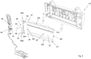
Figure 4 is a split view of the elements ofFigure 3 ; -
Figure 5 is a side view of a mechanical switch, a cam lever and a flap of the vehicle door handle door assembly ofFigure 1 ; -
Figure 6 is a view in perspective of a vehicle door handle door assembly according to a particular embodiment of the invention, taken from another angle. - A
vehicle door assembly 10 according a particular embodiment of the invention has been shown onFigures 1 and2 . -
Door assembly 10 comprises ahousing 12 that sits flush against anouter panel 13 of the vehicle. - The housing comprises an
upper casing 14 and a bowl-shaped reception surface 15, delimiting a volume V giving access to the inside of theupper casing 14. Here, as can be seen onFigure 1 ,reception surface 15 is delimited by aframe 15A having a rectilinear section, the two extremities of which are joined by a U-shaped section. - The
upper casing 14 is substantially rectangular in shape and includes aspace 16 between itsfront wall 17 and itsback wall 18, which is substantially parallel tofront wall 17.Rotatable flap 20 is housed withinspace 16. - As can be seen on
Figure 2 , front wall comprises anupper section 17A which is substantially planar and flush against theouter panel 13 of the vehicle and alower section 17B which is substantially planar but transverse toupper section 17A. More particularly,lower section 17B joinsupper section 17A andreception surface 15 and is connected toreception surface 15 behind the rectilinear section offrame 15A. Hence, the distance betweenlower section 17B offront wall 17 andback wall 18 is lower than the distance betweenupper section 17A andback wall 18. - As can be seen on
Figure 2 ,reception surface 15 is prolonged byback wall 18.Space 16 is connected to the volume V in such a way that the hand of the handle user can be inserted inside volume V and the remaining ofspace 16, in order to actuaterotatable flap 20. To be more precise, the hand is inserted fingers first inside volume V and moves up insidespace 16. Here,space 16 has a width less than 50 mm, preferably above 20mm. - Owing to the narrow space available, most of
space 16 is left hollow to allow passage for the user's hand. Hence,rotatable flap 20 is placed as close as possible tofront wall 17 of the housing. - Turning now to
Figures 3 and4 ,rotatable flap 20 extends along a rotation axis X-X (perpendicular to the plane ofFigure 2 ). To be more precise, as can be seen best onFigure 4 ,rotatable flap 20 is sensibly planar and is delimited, on the one hand, by two parallel rectilinearlongitudinal sides 20L extending along the rotation axis and, on the hand, by two parallel rectilinear lateral sides 20I extending along a direction that is sensibly perpendicular to the rotation axis X-X. -
Rotatable flap 20 comprises afirst section 22 made of elastomer, such as rubber, overmolded on asecond section 24 made of hard plastic, for example polypropylene.First section 22 is placed facingspace 26 so that a hand that is inserted intospace 16 first comes in contact with a surface that is pleasant to the touch. - Preferably,
rotatable flap 20 comprises at itslongitudinal side 20L that is closest to thereception surface 15, i.e. closest to the entrance tospace 16 and proximate to volume V, aboss 27, that extends preferably along the wholelongitudinal side 20L. Thisboss 27 allows the user to easily feel and push onto therotatable flap 20 as soon as their hand is inserted intospace 16. Preferably, the distance between the entrance of volume V andboss 17 is less than 15mm. -
Rotatable flap 20 is configured to rotate about rotation axis X-X between a rest position, which corresponds to the position shown on the Figures, and a door opening position (not shown). - In the present embodiment, the width of the remaining
space 26 betweenrotatable flap 20 andfront wall 17 of the housing, which corresponds to the distance betweenlower section 17B andback wall 18, minus the width ofspace 16 left to insert the user's fingers and the width ofrotatable flap 20 itself, is less than 6mm. Hence, the stroke ofrotatable flap 20 is constrained within this distance. For example, the stroke ofrotatable flap 20, i.e. the distance between therotatable flap 20 in rest position and therotatable flap 20 in door opening position is less than 6mm, preferably less than 4mm. Therotatable flap 20 in rest position and therotatable flap 20 in door opening position form an angle comprised between 2° degrees and 6° degrees. - However, the invention makes it possible for said
rotatable flap 20, even if its stroke is so limited, to activate amechanical actuation switch 28, generating an electrical signal to be sent to a vehicle door controller (not shown) to release the vehicle door. More particularly, the invention makes it possible to have a longer stroke for themechanical actuation switch 28 than therotatable flap 20. - To that end, the
handle assembly 10 also comprises acam holder 30 and acam 32 supported by thecam holder 30.Cam holder 30 is connected to theflap 20 such that it is rotatable about the rotation axis X-X. - The
cam holder 30 comprises acam lever 34 extending along a longitudinal direction, said lever comprising afirst end 34A hinged on the rotation axis X-X of theflap 20 and asecond end 34B, opposite to the first, supporting thecam 32. - More specifically, the axis around which the
cam holder 30 is rotatable is formed by apin 36 stemming from thefirst end 34A of the cam lever inserted into ahole 37 opened in theflap 20 along the rotation axis X-X so that thecam lever 32 is substantially parallel to a lateral side 20I of theflap 20. In the present embodiment, asecond pin 38 inserted in ahole 34H of thecam lever 34 located next to thesecond end 34B of thecam lever 34 is also inserted in asecond hole 39 of theflap 20, located opposite thefirst hole 37 along the lateral side 20I of the flap. - Here, as can be seen on
Figures 3 and4 , the length of thecam lever 34 is at least the same as the length of a lateral side 20I of the flap, here sensibly the same length. - Turning now to
Figures 4 and5 , handleassembly 10 is configured so that that rotation of theflap 20 causes rotation of thecam holder 30, rotation of thecam holder 30 causing thecam 32 to activatemechanical actuation switch 28. - More specifically,
mechanical actuation switch 28 comprises aflexible blade 40 such that during rotation of thecam holder 30, acontact surface 32S of thecam 32 comes into contact with and pushes theblade 40 in at least one direction that is transverse to the rotation axis X-X. Here, theblade 40 extends along a longitudinal axis which is sensibly perpendicular to the rotation axis X-X of the flap. Oneend 41 of theblade 40 is recurved. - As can be better seen on
Figure 5 , thecontact surface 32S of thecam 32 is formed of aslope 42 joining two sensibly rectilinear surfaces 43. Thanks to this configuration, the gradient of theslope 42 determines the stroke speed to push thepush button 44. - The
blade 40 first comes into contact with the firstrectilinear surface 43, which does not actuate theswitch 28 yet. Activation of theswitch 28 becomes possible when theblade 40 comes into contact with theslope 42, which corresponds to the point when theblade 40 also comes into contact with apush button 44 placed oppositeblade 40. Hence, during rotation of thecam holder 30,blade 40 comes into contact with and pushes thepush button 44. Pushing of thepush button 44 generates an electrical signal to be sent to the vehicle door controller to release the vehicle door. - As can be seen on
Figure 6 showing the backside ofdoor handle assembly 10 compared toFigure 1 , it also comprises a back-uprelease mechanism 46 that enables a user to open the vehicle door in case no electric current is available, such as a power shortage in the vehicle. - Back-up
release mechanism 46 comprises acable 48 connected to the door latch mechanism (not shown), causing mechanical actuation of the door latch mechanism to release the vehicle door. - Back-up
release mechanism 46 is configured to be actuated by a key (not shown) inserted in a keyhole located inside thereception surface 15. Here, as can be seen onFigure 1 , the keyhole is hidden by a hidingwall 50 which can be displaced to gain access to the keyhole - Thus one clearly understands that with
little space 16 between theflap 20 and the : back wall of theupper casing 18, the invention achieves a quite compact design of adoor handle assembly 10 for an electrically controlled door latch. This is in particular achieved thanks to the specific location of themechanical actuation switch 28 which is at one side of theflap 20 and oriented with its longitudinal axis perpendicular to the rotation axis X-X of theflap 20 and thanks to theelongated cam holder 30 which amplifies a small pivoting movement to get the necessary stroke to activate thepush button 44 of themechanical switch 28. -
- 10 : Vehicle door assembly
- 12 : Housing
- 13 : Outer panel of the vehicle
- 14 : Upper casing
- 15 : Reception surface
- 15A : Reception surface frame
- 16 : Housing space
- 17 : Front wall of the upper casing
- 17A : Upper section of the front wall
- 17B : Lower section of the front wall
- 18 : Back wall of the upper casing
- 20 : Rotatable flap
- 20L : Longitudinal side of the flap
- 20I: Lateral side of the flap
- 22 : First section of the flap
- 24 : Second section of the flap
- 26 : Remaining space
- 27 : Flap boss
- 28 : Mechanical actuation switch
- 30 : Cam holder
- 32 : Cam
- 32S : Contact surface of the cam
- 34 : Cam lever
- 34A : First end of the cam lever
- 34B : Second end of the cam lever
- 34H : Hole of the cam holder
- 36 : First pin
- 37 : Flap hole
- 38 : Second pin
- 39 : Second flap hole
- 40 : Flexible blade
- 42 : Slope of the cam
- 43: Rectilinear surface
- 44 : Switch push button
- 46 : Back-up release mechanism
- 48 : Cable
- 50 : Hiding wall
- V: Volume delimited by the reception surface
Claims (11)
- Vehicle door handle assembly (10) comprising :- a housing (12) that sits flush against an outer panel (13) of the vehicle,- a rotatable flap (20) housed within said housing (12), said flap (20) extending along and configured to rotate about a rotation axis (X-X) between a rest position and a door opening position,- a mechanical actuation switch (28) generating an electrical signal to be sent to a vehicle door controller to release the vehicle door,wherein it also comprises a cam holder (30) and a cam (32) supported by the cam holder (30), said cam holder (30) being connected to the flap (20) such that the cam holder (30) is rotatable about the rotation axis (X-X) and that rotation of the flap (20) causes rotation of the cam holder (30), rotation of the cam holder (30) causing the cam (32) to activate said mechanical actuation switch (28).wherein the cam holder (30) comprises a cam lever (34) extending along a longitudinal direction, said lever comprising a first end (34A) hinged on the rotation axis (X-X) of the flap (20) and a second end (34B), opposite to the first, supporting the cam (32),wherein the rotatable flap (20) is sensibly planar and is delimited, on the one hand, by two parallel rectilinear longitudinal sides (20L) extending along the rotation axis (X-X) and, on the hand, by two parallel rectilinear lateral sides (20I) extending along a direction that is sensibly perpendicular to the rotation axis (X-X),wherein the axis about which the cam holder (30) is rotatable is a pin (36) stemming from the first end (34A) of the cam lever configured to be inserted into a hole (37) opened in the flap (20) along the rotation axis (X-X), such that the cam lever (34) is substantially parallel to a lateral side of the flap (20).
- Vehicle door hand assembly (10) according to claim 1, wherein the length of the cam lever (34) is at least the same as the length of a lateral side of the flap (20).
- Vehicle door handle assembly (10) according to any one of the preceding claims, wherein the mechanical actuation switch (28) comprises a flexible blade (40) and wherein during rotation of the cam holder (30), a contact surface of the cam (32S) comes into contact with and pushes the blade (40) in at least one direction that is transverse to the rotation axis (X-X).
- Vehicle door handle (10) assembly according to claim 3, wherein, the blade (40) is oriented sensibly perpendicularly to the rotation axis (X-X) of the flap.
- Vehicle door handle assembly (10) according to claim 3 or 4, wherein the mechanical actuation switch (28) comprises a push button (44) and wherein during rotation of the cam holder (30), the blade (40) comes into contact with and pushes the push button (44), said pushing of the push button (44) generating an electrical signal to be sent to a vehicle door controller to release the vehicle door.
- Vehicle door handle assembly (10) according to any one of the preceding claims, wherein the contact surface (32S) of the cam is formed of a slope (42) joining two sensibly rectilinear surfaces (43).
- Vehicle door handle assembly (10) according to any one of the preceding claims, wherein the housing (12) comprises a bowl-shaped reception surface (15), delimiting a volume (V) giving access to the rotatable flap (20).
- Vehicle door handle assembly (10) according to any one of the preceding claims, wherein the rotatable flap (20) in rest position and the rotatable flap (20) in door opening position form an angle comprised between 2° degrees and 6° degrees.
- Vehicle door handle assembly (10) according to any one of the preceding claims, wherein the distance between the rotatable flap (20) in rest position and the rotatable flap (20) in door opening position is less than 6mm, preferably less than 4mm.
- Vehicle door handle assembly (10) according to any one of the preceding claims, wherein it also comprises a back-up release mechanism (46) comprising a cable (48) connected to the door latch mechanism, causing mechanical actuation of the door latch mechanism to release the vehicle door, said back-up release mechanism (46) being configured to be actuated by a key inserted in a keyhole located inside the reception surface (15).
- Vehicle door handle assembly (10) according to any one of the preceding claims, wherein the rotatable flap (20) comprises for example a section (22) made of elastomer, such as rubber, overmolded on a section (24) made of hard plastic, for example polypropylene.
Priority Applications (6)
| Application Number | Priority Date | Filing Date | Title |
|---|---|---|---|
| ES21150431T ES3004357T3 (en) | 2021-01-06 | 2021-01-06 | Electronic vehicle handle assembly including a mechanical switch |
| EP21150431.1A EP4026972B1 (en) | 2021-01-06 | 2021-01-06 | Electronic vehicle handle assembly including a mechanical switch |
| PCT/EP2022/050210 WO2022148814A1 (en) | 2021-01-06 | 2022-01-06 | Electronic vehicle handle assembly including a mechanical switch |
| JP2023540998A JP7737458B2 (en) | 2021-01-06 | 2022-01-06 | Steering wheel assembly for electric vehicle including mechanical switch |
| CN202280009113.0A CN116710625A (en) | 2021-01-06 | 2022-01-06 | Electronic vehicle handlebar assemblies including mechanical switches |
| US18/259,651 US12534940B2 (en) | 2021-01-06 | 2022-01-06 | Electronic vehicle handle assembly including a mechanical switch |
Applications Claiming Priority (1)
| Application Number | Priority Date | Filing Date | Title |
|---|---|---|---|
| EP21150431.1A EP4026972B1 (en) | 2021-01-06 | 2021-01-06 | Electronic vehicle handle assembly including a mechanical switch |
Publications (2)
| Publication Number | Publication Date |
|---|---|
| EP4026972A1 EP4026972A1 (en) | 2022-07-13 |
| EP4026972B1 true EP4026972B1 (en) | 2024-10-09 |
Family
ID=74141357
Family Applications (1)
| Application Number | Title | Priority Date | Filing Date |
|---|---|---|---|
| EP21150431.1A Active EP4026972B1 (en) | 2021-01-06 | 2021-01-06 | Electronic vehicle handle assembly including a mechanical switch |
Country Status (6)
| Country | Link |
|---|---|
| US (1) | US12534940B2 (en) |
| EP (1) | EP4026972B1 (en) |
| JP (1) | JP7737458B2 (en) |
| CN (1) | CN116710625A (en) |
| ES (1) | ES3004357T3 (en) |
| WO (1) | WO2022148814A1 (en) |
Families Citing this family (1)
| Publication number | Priority date | Publication date | Assignee | Title |
|---|---|---|---|---|
| EP4343091A1 (en) * | 2022-09-20 | 2024-03-27 | Minebea AccessSolutions Italia S.p.A. | Device for identifying a position of a vehicle handle |
Family Cites Families (28)
| Publication number | Priority date | Publication date | Assignee | Title |
|---|---|---|---|---|
| JPS628301Y2 (en) * | 1985-09-12 | 1987-02-26 | ||
| JPS62248769A (en) * | 1986-04-22 | 1987-10-29 | 富士重工業株式会社 | Keyless entry apparatus of car |
| DE3712376C1 (en) * | 1987-04-11 | 1988-08-18 | Daimler Benz Ag | Swiveling handle for doors, flaps or covers of vehicles |
| JPH0765413B2 (en) * | 1987-12-18 | 1995-07-19 | 株式会社アルファ | How to make an antistatic knob |
| JPH01134160U (en) * | 1988-03-04 | 1989-09-13 | ||
| JPH09250265A (en) * | 1996-01-10 | 1997-09-22 | Tokai Rika Co Ltd | Door lock releasing device for vehicle |
| JP3667850B2 (en) * | 1996-01-11 | 2005-07-06 | 株式会社東海理化電機製作所 | Wireless door lock device |
| DE19933646C2 (en) * | 1999-07-17 | 2003-05-28 | Valeo Gmbh & Co Schliessyst Kg | Door handle for a vehicle door |
| IT1310150B1 (en) * | 1999-08-31 | 2002-02-11 | Valeo Sicurezza Abitacolo Spa | HANDLE FOR A VEHICLE DOOR |
| FR2802962B1 (en) * | 1999-12-23 | 2002-02-15 | Valeo Securite Habitacle | MOTOR VEHICLE OPENING HANDLE COMPRISING IMPROVED MEANS FOR ACTUATING SWITCHING DEVICES |
| DE10000863C1 (en) * | 2000-01-12 | 2001-05-31 | Huf Huelsbeck & Fuerst Gmbh | Fitting of a door handle into the opening of a vehicle door has a groove at the housing to fit at an edge for a swing movement into place by a tilting linkage with spreader forces for a secure fit without free play |
| US6349450B1 (en) * | 2000-06-20 | 2002-02-26 | Donnelly Corporation | Vehicle door handle |
| KR101012996B1 (en) * | 2002-07-30 | 2011-02-10 | 후프 휠스벡 운트 퓌르스트 게엠베하 운트 콤파니 카게 | Latch for a mobile part of a vehicle body |
| US6923481B2 (en) * | 2003-01-15 | 2005-08-02 | Daimlerchrysler Corporation | Flush exterior door handle |
| DE102006048371A1 (en) * | 2006-10-09 | 2008-04-10 | Huf Hülsbeck & Fürst Gmbh & Co. Kg | Device for pivoting a movable part |
| ES1064403Y (en) * | 2006-12-14 | 2007-06-01 | Seat Sa | LOCK FOR CAR DOORS AND GATES |
| JP5078966B2 (en) * | 2009-10-07 | 2012-11-21 | 株式会社ホンダロック | Vehicle door handle device |
| JP5638014B2 (en) * | 2012-01-24 | 2014-12-10 | 株式会社ホンダロック | Vehicle door opening / closing operation device |
| JP5961451B2 (en) | 2012-05-31 | 2016-08-02 | 富士重工業株式会社 | Bonding structure of fiber reinforced resin and metal |
| GB2517348B (en) * | 2012-09-25 | 2015-09-23 | Jaguar Land Rover Ltd | Retractable handle arrangement |
| DE102013102106A1 (en) * | 2013-03-04 | 2014-09-04 | Huf Hülsbeck & Fürst Gmbh & Co. Kg | Outside door handle arrangement |
| DE102016113695A1 (en) * | 2016-07-25 | 2018-01-25 | Witte Automotive Gmbh | The door handle assembly |
| DE102016218206A1 (en) * | 2016-09-22 | 2018-03-22 | Volkswagen Aktiengesellschaft | Unlocking unit with a variable trip switching point |
| DE102017101654A1 (en) * | 2017-01-27 | 2018-08-02 | Huf Hülsbeck & Fürst Gmbh & Co. Kg | Motor vehicle actuator |
| JP6769419B2 (en) * | 2017-09-26 | 2020-10-14 | 豊田合成株式会社 | Backdoor open / close switch |
| EP3502166A1 (en) * | 2017-12-22 | 2019-06-26 | SABIC Global Technologies B.V. | Polypropylene composition comprising glass fibers |
| DE102018117961A1 (en) * | 2018-07-25 | 2020-01-30 | Huf Hülsbeck & Fürst Gmbh & Co. Kg | Handle arrangement of a motor vehicle |
| JP7135802B2 (en) * | 2018-12-04 | 2022-09-13 | トヨタ自動車株式会社 | vehicle door device |
-
2021
- 2021-01-06 EP EP21150431.1A patent/EP4026972B1/en active Active
- 2021-01-06 ES ES21150431T patent/ES3004357T3/en active Active
-
2022
- 2022-01-06 JP JP2023540998A patent/JP7737458B2/en active Active
- 2022-01-06 WO PCT/EP2022/050210 patent/WO2022148814A1/en not_active Ceased
- 2022-01-06 US US18/259,651 patent/US12534940B2/en active Active
- 2022-01-06 CN CN202280009113.0A patent/CN116710625A/en active Pending
Also Published As
| Publication number | Publication date |
|---|---|
| EP4026972A1 (en) | 2022-07-13 |
| US20240060339A1 (en) | 2024-02-22 |
| JP7737458B2 (en) | 2025-09-10 |
| CN116710625A (en) | 2023-09-05 |
| ES3004357T3 (en) | 2025-03-12 |
| WO2022148814A1 (en) | 2022-07-14 |
| JP2024502441A (en) | 2024-01-19 |
| US12534940B2 (en) | 2026-01-27 |
Similar Documents
| Publication | Publication Date | Title |
|---|---|---|
| JP7079564B2 (en) | Vehicle door handle | |
| US8146965B2 (en) | Vehicle door lock device | |
| US6765472B2 (en) | Security system for a motor vehicle opening leaf equipped with switches | |
| JP4405312B2 (en) | Sliding door locking device | |
| US7377557B2 (en) | Scissor mechanism for a latch assembly | |
| EP3712362B1 (en) | Door handle assembly comprising an outer bezel mechanism and an inner bracket mechanism | |
| EP2620569B1 (en) | Latch releasing system for vehicle door | |
| EP2792829B1 (en) | Vehicle door latch system | |
| US6108979A (en) | Vehicle handle linear pull action | |
| JP2011063146A (en) | Open switch erroneous operation prevention structure for tail gate | |
| US12534940B2 (en) | Electronic vehicle handle assembly including a mechanical switch | |
| US4850625A (en) | Automotive door lock device with anit-theft structure | |
| US12168895B2 (en) | Electronic vehicle handle assembly including a mechanical switch for a scissors door | |
| JP2012007342A (en) | Vehicular opening/closing body locking device | |
| EP4435210A1 (en) | Vehicle door handle device | |
| EP4108866B1 (en) | Vehicle door handle assembly attachment unit | |
| JP2025129722A (en) | Door handle device for vehicle | |
| EP4108872A1 (en) | Vehicle opening element handle assembly | |
| JP2024145619A (en) | Door opening device | |
| EP4108865B1 (en) | Vehicle door handle assembly | |
| EP4628688A1 (en) | Door handle device | |
| JP2024145606A (en) | Door opening device | |
| JP2025129721A (en) | Door handle device for vehicle | |
| JP2026005615A (en) | Vehicle door lock device | |
| WO2011002770A1 (en) | Vehicle door-latch manual release |
Legal Events
| Date | Code | Title | Description |
|---|---|---|---|
| PUAI | Public reference made under article 153(3) epc to a published international application that has entered the european phase |
Free format text: ORIGINAL CODE: 0009012 |
|
| STAA | Information on the status of an ep patent application or granted ep patent |
Free format text: STATUS: THE APPLICATION HAS BEEN PUBLISHED |
|
| AK | Designated contracting states |
Kind code of ref document: A1 Designated state(s): AL AT BE BG CH CY CZ DE DK EE ES FI FR GB GR HR HU IE IS IT LI LT LU LV MC MK MT NL NO PL PT RO RS SE SI SK SM TR |
|
| STAA | Information on the status of an ep patent application or granted ep patent |
Free format text: STATUS: REQUEST FOR EXAMINATION WAS MADE |
|
| 17P | Request for examination filed |
Effective date: 20230113 |
|
| RBV | Designated contracting states (corrected) |
Designated state(s): AL AT BE BG CH CY CZ DE DK EE ES FI FR GB GR HR HU IE IS IT LI LT LU LV MC MK MT NL NO PL PT RO RS SE SI SK SM TR |
|
| RAP3 | Party data changed (applicant data changed or rights of an application transferred) |
Owner name: MINEBEA ACCESSSOLUTIONS ITALIA S.P.A. |
|
| GRAP | Despatch of communication of intention to grant a patent |
Free format text: ORIGINAL CODE: EPIDOSNIGR1 |
|
| STAA | Information on the status of an ep patent application or granted ep patent |
Free format text: STATUS: GRANT OF PATENT IS INTENDED |
|
| INTG | Intention to grant announced |
Effective date: 20240514 |
|
| GRAS | Grant fee paid |
Free format text: ORIGINAL CODE: EPIDOSNIGR3 |
|
| GRAA | (expected) grant |
Free format text: ORIGINAL CODE: 0009210 |
|
| STAA | Information on the status of an ep patent application or granted ep patent |
Free format text: STATUS: THE PATENT HAS BEEN GRANTED |
|
| AK | Designated contracting states |
Kind code of ref document: B1 Designated state(s): AL AT BE BG CH CY CZ DE DK EE ES FI FR GB GR HR HU IE IS IT LI LT LU LV MC MK MT NL NO PL PT RO RS SE SI SK SM TR |
|
| REG | Reference to a national code |
Ref country code: CH Ref legal event code: EP |
|
| REG | Reference to a national code |
Ref country code: DE Ref legal event code: R096 Ref document number: 602021019749 Country of ref document: DE |
|
| REG | Reference to a national code |
Ref country code: IE Ref legal event code: FG4D |
|
| REG | Reference to a national code |
Ref country code: LT Ref legal event code: MG9D |
|
| REG | Reference to a national code |
Ref country code: NL Ref legal event code: MP Effective date: 20241009 |
|
| REG | Reference to a national code |
Ref country code: ES Ref legal event code: FG2A Ref document number: 3004357 Country of ref document: ES Kind code of ref document: T3 Effective date: 20250312 |
|
| REG | Reference to a national code |
Ref country code: AT Ref legal event code: MK05 Ref document number: 1730763 Country of ref document: AT Kind code of ref document: T Effective date: 20241009 |
|
| PG25 | Lapsed in a contracting state [announced via postgrant information from national office to epo] |
Ref country code: NL Free format text: LAPSE BECAUSE OF FAILURE TO SUBMIT A TRANSLATION OF THE DESCRIPTION OR TO PAY THE FEE WITHIN THE PRESCRIBED TIME-LIMIT Effective date: 20241009 |
|
| PG25 | Lapsed in a contracting state [announced via postgrant information from national office to epo] |
Ref country code: NL Free format text: LAPSE BECAUSE OF FAILURE TO SUBMIT A TRANSLATION OF THE DESCRIPTION OR TO PAY THE FEE WITHIN THE PRESCRIBED TIME-LIMIT Effective date: 20241009 |
|
| PG25 | Lapsed in a contracting state [announced via postgrant information from national office to epo] |
Ref country code: PT Free format text: LAPSE BECAUSE OF FAILURE TO SUBMIT A TRANSLATION OF THE DESCRIPTION OR TO PAY THE FEE WITHIN THE PRESCRIBED TIME-LIMIT Effective date: 20250210 Ref country code: HR Free format text: LAPSE BECAUSE OF FAILURE TO SUBMIT A TRANSLATION OF THE DESCRIPTION OR TO PAY THE FEE WITHIN THE PRESCRIBED TIME-LIMIT Effective date: 20241009 Ref country code: IS Free format text: LAPSE BECAUSE OF FAILURE TO SUBMIT A TRANSLATION OF THE DESCRIPTION OR TO PAY THE FEE WITHIN THE PRESCRIBED TIME-LIMIT Effective date: 20250209 |
|
| PG25 | Lapsed in a contracting state [announced via postgrant information from national office to epo] |
Ref country code: FI Free format text: LAPSE BECAUSE OF FAILURE TO SUBMIT A TRANSLATION OF THE DESCRIPTION OR TO PAY THE FEE WITHIN THE PRESCRIBED TIME-LIMIT Effective date: 20241009 |
|
| PG25 | Lapsed in a contracting state [announced via postgrant information from national office to epo] |
Ref country code: BG Free format text: LAPSE BECAUSE OF FAILURE TO SUBMIT A TRANSLATION OF THE DESCRIPTION OR TO PAY THE FEE WITHIN THE PRESCRIBED TIME-LIMIT Effective date: 20241009 |
|
| PG25 | Lapsed in a contracting state [announced via postgrant information from national office to epo] |
Ref country code: NO Free format text: LAPSE BECAUSE OF FAILURE TO SUBMIT A TRANSLATION OF THE DESCRIPTION OR TO PAY THE FEE WITHIN THE PRESCRIBED TIME-LIMIT Effective date: 20250109 |
|
| PG25 | Lapsed in a contracting state [announced via postgrant information from national office to epo] |
Ref country code: GR Free format text: LAPSE BECAUSE OF FAILURE TO SUBMIT A TRANSLATION OF THE DESCRIPTION OR TO PAY THE FEE WITHIN THE PRESCRIBED TIME-LIMIT Effective date: 20250110 Ref country code: LV Free format text: LAPSE BECAUSE OF FAILURE TO SUBMIT A TRANSLATION OF THE DESCRIPTION OR TO PAY THE FEE WITHIN THE PRESCRIBED TIME-LIMIT Effective date: 20241009 Ref country code: AT Free format text: LAPSE BECAUSE OF FAILURE TO SUBMIT A TRANSLATION OF THE DESCRIPTION OR TO PAY THE FEE WITHIN THE PRESCRIBED TIME-LIMIT Effective date: 20241009 |
|
| PG25 | Lapsed in a contracting state [announced via postgrant information from national office to epo] |
Ref country code: PL Free format text: LAPSE BECAUSE OF FAILURE TO SUBMIT A TRANSLATION OF THE DESCRIPTION OR TO PAY THE FEE WITHIN THE PRESCRIBED TIME-LIMIT Effective date: 20241009 |
|
| PG25 | Lapsed in a contracting state [announced via postgrant information from national office to epo] |
Ref country code: RS Free format text: LAPSE BECAUSE OF FAILURE TO SUBMIT A TRANSLATION OF THE DESCRIPTION OR TO PAY THE FEE WITHIN THE PRESCRIBED TIME-LIMIT Effective date: 20250109 |
|
| PG25 | Lapsed in a contracting state [announced via postgrant information from national office to epo] |
Ref country code: SM Free format text: LAPSE BECAUSE OF FAILURE TO SUBMIT A TRANSLATION OF THE DESCRIPTION OR TO PAY THE FEE WITHIN THE PRESCRIBED TIME-LIMIT Effective date: 20241009 |
|
| PG25 | Lapsed in a contracting state [announced via postgrant information from national office to epo] |
Ref country code: DK Free format text: LAPSE BECAUSE OF FAILURE TO SUBMIT A TRANSLATION OF THE DESCRIPTION OR TO PAY THE FEE WITHIN THE PRESCRIBED TIME-LIMIT Effective date: 20241009 |
|
| REG | Reference to a national code |
Ref country code: DE Ref legal event code: R097 Ref document number: 602021019749 Country of ref document: DE |
|
| PG25 | Lapsed in a contracting state [announced via postgrant information from national office to epo] |
Ref country code: EE Free format text: LAPSE BECAUSE OF FAILURE TO SUBMIT A TRANSLATION OF THE DESCRIPTION OR TO PAY THE FEE WITHIN THE PRESCRIBED TIME-LIMIT Effective date: 20241009 |
|
| PG25 | Lapsed in a contracting state [announced via postgrant information from national office to epo] |
Ref country code: RO Free format text: LAPSE BECAUSE OF FAILURE TO SUBMIT A TRANSLATION OF THE DESCRIPTION OR TO PAY THE FEE WITHIN THE PRESCRIBED TIME-LIMIT Effective date: 20241009 |
|
| PG25 | Lapsed in a contracting state [announced via postgrant information from national office to epo] |
Ref country code: SK Free format text: LAPSE BECAUSE OF FAILURE TO SUBMIT A TRANSLATION OF THE DESCRIPTION OR TO PAY THE FEE WITHIN THE PRESCRIBED TIME-LIMIT Effective date: 20241009 |
|
| PG25 | Lapsed in a contracting state [announced via postgrant information from national office to epo] |
Ref country code: CZ Free format text: LAPSE BECAUSE OF FAILURE TO SUBMIT A TRANSLATION OF THE DESCRIPTION OR TO PAY THE FEE WITHIN THE PRESCRIBED TIME-LIMIT Effective date: 20241009 |
|
| PLBE | No opposition filed within time limit |
Free format text: ORIGINAL CODE: 0009261 |
|
| STAA | Information on the status of an ep patent application or granted ep patent |
Free format text: STATUS: NO OPPOSITION FILED WITHIN TIME LIMIT |
|
| REG | Reference to a national code |
Ref country code: CH Ref legal event code: PL |
|
| PG25 | Lapsed in a contracting state [announced via postgrant information from national office to epo] |
Ref country code: SE Free format text: LAPSE BECAUSE OF FAILURE TO SUBMIT A TRANSLATION OF THE DESCRIPTION OR TO PAY THE FEE WITHIN THE PRESCRIBED TIME-LIMIT Effective date: 20241009 |
|
| PG25 | Lapsed in a contracting state [announced via postgrant information from national office to epo] |
Ref country code: MC Free format text: LAPSE BECAUSE OF FAILURE TO SUBMIT A TRANSLATION OF THE DESCRIPTION OR TO PAY THE FEE WITHIN THE PRESCRIBED TIME-LIMIT Effective date: 20241009 Ref country code: LU Free format text: LAPSE BECAUSE OF NON-PAYMENT OF DUE FEES Effective date: 20250106 |
|
| 26N | No opposition filed |
Effective date: 20250710 |
|
| GBPC | Gb: european patent ceased through non-payment of renewal fee |
Effective date: 20250109 |
|
| PG25 | Lapsed in a contracting state [announced via postgrant information from national office to epo] |
Ref country code: BE Free format text: LAPSE BECAUSE OF NON-PAYMENT OF DUE FEES Effective date: 20250131 Ref country code: GB Free format text: LAPSE BECAUSE OF NON-PAYMENT OF DUE FEES Effective date: 20250109 |
|
| PG25 | Lapsed in a contracting state [announced via postgrant information from national office to epo] |
Ref country code: CH Free format text: LAPSE BECAUSE OF NON-PAYMENT OF DUE FEES Effective date: 20250131 |
|
| REG | Reference to a national code |
Ref country code: BE Ref legal event code: MM Effective date: 20250131 |
|
| PG25 | Lapsed in a contracting state [announced via postgrant information from national office to epo] |
Ref country code: IE Free format text: LAPSE BECAUSE OF NON-PAYMENT OF DUE FEES Effective date: 20250106 |
|
| PGFP | Annual fee paid to national office [announced via postgrant information from national office to epo] |
Ref country code: ES Payment date: 20260209 Year of fee payment: 6 |
|
| PGFP | Annual fee paid to national office [announced via postgrant information from national office to epo] |
Ref country code: DE Payment date: 20260114 Year of fee payment: 6 |
|
| PGFP | Annual fee paid to national office [announced via postgrant information from national office to epo] |
Ref country code: IT Payment date: 20260107 Year of fee payment: 6 |
|
| PGFP | Annual fee paid to national office [announced via postgrant information from national office to epo] |
Ref country code: FR Payment date: 20260128 Year of fee payment: 6 |