EP4026762A1 - Wheel speed sensor mounting structure - Google Patents
Wheel speed sensor mounting structure Download PDFInfo
- Publication number
- EP4026762A1 EP4026762A1 EP19944099.1A EP19944099A EP4026762A1 EP 4026762 A1 EP4026762 A1 EP 4026762A1 EP 19944099 A EP19944099 A EP 19944099A EP 4026762 A1 EP4026762 A1 EP 4026762A1
- Authority
- EP
- European Patent Office
- Prior art keywords
- speed sensor
- wheel
- wheel speed
- sensor
- support member
- Prior art date
- Legal status (The legal status is an assumption and is not a legal conclusion. Google has not performed a legal analysis and makes no representation as to the accuracy of the status listed.)
- Granted
Links
- 230000001681 protective effect Effects 0.000 claims description 28
- 230000005540 biological transmission Effects 0.000 description 14
- 210000000078 claw Anatomy 0.000 description 12
- 238000001514 detection method Methods 0.000 description 12
- 238000003780 insertion Methods 0.000 description 6
- 230000037431 insertion Effects 0.000 description 6
- 239000011347 resin Substances 0.000 description 3
- 229920005989 resin Polymers 0.000 description 3
- 230000003014 reinforcing effect Effects 0.000 description 2
- 239000000725 suspension Substances 0.000 description 2
- 239000006096 absorbing agent Substances 0.000 description 1
- 238000006243 chemical reaction Methods 0.000 description 1
- 238000002485 combustion reaction Methods 0.000 description 1
- 230000000694 effects Effects 0.000 description 1
- 239000013013 elastic material Substances 0.000 description 1
- 230000004907 flux Effects 0.000 description 1
- 238000009434 installation Methods 0.000 description 1
- 239000002184 metal Substances 0.000 description 1
- 238000000034 method Methods 0.000 description 1
- 230000000149 penetrating effect Effects 0.000 description 1
- 230000035939 shock Effects 0.000 description 1
- 230000003584 silencer Effects 0.000 description 1
Images


Classifications
-
- B—PERFORMING OPERATIONS; TRANSPORTING
- B62—LAND VEHICLES FOR TRAVELLING OTHERWISE THAN ON RAILS
- B62J—CYCLE SADDLES OR SEATS; AUXILIARY DEVICES OR ACCESSORIES SPECIALLY ADAPTED TO CYCLES AND NOT OTHERWISE PROVIDED FOR, e.g. ARTICLE CARRIERS OR CYCLE PROTECTORS
- B62J45/00—Electrical equipment arrangements specially adapted for use as accessories on cycles, not otherwise provided for
- B62J45/40—Sensor arrangements; Mounting thereof
- B62J45/41—Sensor arrangements; Mounting thereof characterised by the type of sensor
- B62J45/413—Rotation sensors
-
- B—PERFORMING OPERATIONS; TRANSPORTING
- B60—VEHICLES IN GENERAL
- B60T—VEHICLE BRAKE CONTROL SYSTEMS OR PARTS THEREOF; BRAKE CONTROL SYSTEMS OR PARTS THEREOF, IN GENERAL; ARRANGEMENT OF BRAKING ELEMENTS ON VEHICLES IN GENERAL; PORTABLE DEVICES FOR PREVENTING UNWANTED MOVEMENT OF VEHICLES; VEHICLE MODIFICATIONS TO FACILITATE COOLING OF BRAKES
- B60T8/00—Arrangements for adjusting wheel-braking force to meet varying vehicular or ground-surface conditions, e.g. limiting or varying distribution of braking force
- B60T8/32—Arrangements for adjusting wheel-braking force to meet varying vehicular or ground-surface conditions, e.g. limiting or varying distribution of braking force responsive to a speed condition, e.g. acceleration or deceleration
- B60T8/321—Arrangements for adjusting wheel-braking force to meet varying vehicular or ground-surface conditions, e.g. limiting or varying distribution of braking force responsive to a speed condition, e.g. acceleration or deceleration deceleration
- B60T8/3225—Systems specially adapted for single-track vehicles, e.g. motorcycles
-
- B—PERFORMING OPERATIONS; TRANSPORTING
- B60—VEHICLES IN GENERAL
- B60T—VEHICLE BRAKE CONTROL SYSTEMS OR PARTS THEREOF; BRAKE CONTROL SYSTEMS OR PARTS THEREOF, IN GENERAL; ARRANGEMENT OF BRAKING ELEMENTS ON VEHICLES IN GENERAL; PORTABLE DEVICES FOR PREVENTING UNWANTED MOVEMENT OF VEHICLES; VEHICLE MODIFICATIONS TO FACILITATE COOLING OF BRAKES
- B60T8/00—Arrangements for adjusting wheel-braking force to meet varying vehicular or ground-surface conditions, e.g. limiting or varying distribution of braking force
- B60T8/32—Arrangements for adjusting wheel-braking force to meet varying vehicular or ground-surface conditions, e.g. limiting or varying distribution of braking force responsive to a speed condition, e.g. acceleration or deceleration
- B60T8/321—Arrangements for adjusting wheel-braking force to meet varying vehicular or ground-surface conditions, e.g. limiting or varying distribution of braking force responsive to a speed condition, e.g. acceleration or deceleration deceleration
- B60T8/329—Systems characterised by their speed sensor arrangements
-
- B—PERFORMING OPERATIONS; TRANSPORTING
- B62—LAND VEHICLES FOR TRAVELLING OTHERWISE THAN ON RAILS
- B62J—CYCLE SADDLES OR SEATS; AUXILIARY DEVICES OR ACCESSORIES SPECIALLY ADAPTED TO CYCLES AND NOT OTHERWISE PROVIDED FOR, e.g. ARTICLE CARRIERS OR CYCLE PROTECTORS
- B62J45/00—Electrical equipment arrangements specially adapted for use as accessories on cycles, not otherwise provided for
- B62J45/40—Sensor arrangements; Mounting thereof
- B62J45/42—Sensor arrangements; Mounting thereof characterised by mounting
- B62J45/423—Sensor arrangements; Mounting thereof characterised by mounting on or besides the wheel
-
- B—PERFORMING OPERATIONS; TRANSPORTING
- B62—LAND VEHICLES FOR TRAVELLING OTHERWISE THAN ON RAILS
- B62K—CYCLES; CYCLE FRAMES; CYCLE STEERING DEVICES; RIDER-OPERATED TERMINAL CONTROLS SPECIALLY ADAPTED FOR CYCLES; CYCLE AXLE SUSPENSIONS; CYCLE SIDE-CARS, FORECARS, OR THE LIKE
- B62K19/00—Cycle frames
- B62K19/30—Frame parts shaped to receive other cycle parts or accessories
- B62K19/38—Frame parts shaped to receive other cycle parts or accessories for attaching brake members
-
- G—PHYSICS
- G01—MEASURING; TESTING
- G01P—MEASURING LINEAR OR ANGULAR SPEED, ACCELERATION, DECELERATION, OR SHOCK; INDICATING PRESENCE, ABSENCE, OR DIRECTION, OF MOVEMENT
- G01P3/00—Measuring linear or angular speed; Measuring differences of linear or angular speeds
- G01P3/42—Devices characterised by the use of electric or magnetic means
- G01P3/44—Devices characterised by the use of electric or magnetic means for measuring angular speed
- G01P3/48—Devices characterised by the use of electric or magnetic means for measuring angular speed by measuring frequency of generated current or voltage
- G01P3/481—Devices characterised by the use of electric or magnetic means for measuring angular speed by measuring frequency of generated current or voltage of pulse signals
- G01P3/488—Devices characterised by the use of electric or magnetic means for measuring angular speed by measuring frequency of generated current or voltage of pulse signals delivered by variable reluctance detectors
-
- G—PHYSICS
- G01—MEASURING; TESTING
- G01P—MEASURING LINEAR OR ANGULAR SPEED, ACCELERATION, DECELERATION, OR SHOCK; INDICATING PRESENCE, ABSENCE, OR DIRECTION, OF MOVEMENT
- G01P1/00—Details of instruments
- G01P1/02—Housings
- G01P1/026—Housings for speed measuring devices, e.g. pulse generator
Definitions
- the present invention relates to a wheel speed sensor mounting structure.
- a wheel speed sensor may be provided in a wheel to employ an anti-lock brake system (ABS) or a traction control system (TCS).
- ABS anti-lock brake system
- TCS traction control system
- Patent Document 1 discloses a configuration in which a wheel speed sensor is mounted on a swing arm supporting a rear wheel from an outer side in a vehicle width direction, and the wheel speed sensor and a sensor cable are covered with a separate cover member from an outer side in the vehicle width direction.
- Patent Document 1 Japanese Patent No. 4856495
- the present invention provides a wheel speed sensor mounting structure in which an influence on an external appearance due to provision of a wheel speed sensor can be minimized, and positional accuracy for the wheel speed sensor can be secured.
- an first aspect of the present invention is a wheel speed sensor mounting structure including a wheel support member (38) supported by a vehicle body (F) and configured to support a wheel (WR), and a wheel speed sensor (51) detecting a rotation speed of the wheel (WR), in which the wheel speed sensor (51) is disposed on an inner side of the wheel support member (38) in a vehicle width direction, and at least a part thereof is disposed in a region (N) surrounded by an axle (AR) of the wheel (WR) and chassis component attachment parts (38c1 and 38c2) of the wheel support member (38) in a side view.
- a wheel speed sensor mounting structure including a wheel support member (38) supported by a vehicle body (F) and configured to support a wheel (WR), and a wheel speed sensor (51) detecting a rotation speed of the wheel (WR), in which the wheel speed sensor (51) is disposed on an inner side of the wheel support member (38) in a vehicle width direction, and at least a part thereof is disposed in a region (N) surrounded by an
- the wheel speed sensor since the wheel speed sensor is mounted on an inner side of the wheel support member in the vehicle width direction, the wheel speed sensor is unlikely to be visually noticeable, and an influence on an external appearance can be minimized. Also, when the wheel speed sensor is mounted, since the rear wheel axle and the chassis component attachment parts make it easy to find the sensor mounting part, the following effects are achieved. That is, mounting workability of the wheel speed sensor can be improved, and positional accuracy for the wheel speed sensor can be secured.
- a second aspect of the present invention may, in the first aspect described above, further include a positioning part (61) provided on the inner side of the wheel support member (38) in the vehicle width direction, adjacent to a sensor fastening part (63) which fastens the wheel speed sensor (51), and used for positioning of the wheel speed sensor (51).
- a third aspect of the present invention may, in the second aspect described above, further include a second positioning part (62) provided on the inner side of the wheel support member (38) in the vehicle width direction, separated from the sensor fastening part (63) and the positioning part (61), and used for positioning of the wheel speed sensor (51) in a rotational direction with respect to a center of the fastening part.
- a second positioning part (62) provided on the inner side of the wheel support member (38) in the vehicle width direction, separated from the sensor fastening part (63) and the positioning part (61), and used for positioning of the wheel speed sensor (51) in a rotational direction with respect to a center of the fastening part.
- the second positioning part (62) may include a surrounding part (62a) formed to follow an engaged part (51d) at a portion engaging with the engaged part (51d) of the wheel speed sensor (51).
- the wheel speed sensor (51) may be covered with a protective member (52) and fastened to the wheel support member (38) together with the protective member (52).
- the wheel speed sensor can be better protected, and the protective member can be jointly fastened and fixed with the wheel speed sensor to improve mounting workability.
- the wheel speed sensor (51) may be mounted on the wheel support member (38) in a state in which it is sandwiched between a holding part (52d) provided in the protective member (52) and the positioning part (61) provided on the inner side of the wheel support member (38) in the vehicle width direction.
- the present invention it is possible to provide a wheel speed sensor mounting structure in which an influence on an external appearance due to provision of a wheel speed sensor can be minimized, and positional accuracy for the wheel speed sensor can be secured.
- a motorcycle (straddle-type vehicle) 1 of the present embodiment includes a head pipe 13 at a front end portion of a vehicle body frame F.
- a front fork 11 that rotatably supports a front wheel WF and a steering handlebar 12 are supported by the head pipe 13 to be steerable.
- a lower side of a front portion of a swing-type power unit (hereinafter referred to as a power unit U) is supported to be vertically swingable.
- the motorcycle 1 is a straddle-type vehicle of a unit swing type including the power unit U in which an engine (internal combustion engine) E serving as a prime mover and a rear wheel WR serving as a drive wheel swing integrally with respect to the vehicle body frame F (vehicle main body).
- an engine internal combustion engine
- a rear wheel WR serving as a drive wheel swing integrally with respect to the vehicle body frame F (vehicle main body).
- the power unit U is an integrated unit in which the engine E serving as a prime mover of the motorcycle 1 is disposed at a portion in front, and a transmission M for shifting an output from the engine E is disposed on a left side of a rear portion.
- An axle (rear wheel axle) AR of the rear wheel WR serving as a drive wheel is supported at a rear portion of the transmission M.
- a front portion of the power unit U is supported by a support part of the vehicle body frame F to be vertically swingable via a suspension link or the like.
- a rear end portion of the power unit U is supported by a rear end portion of the vehicle body frame F via a pair of left and right rear cushions 9 which are shock absorbers.
- reference sign WRa indicates a wheel of the rear wheel WR
- reference sign WRc indicates a central axis of the rear wheel WR (axle AR).
- the vehicle body frame F includes a down frame 14 extending downward and rearward from the head pipe 13, a lower frame 15 extending rearward from a lower end portion of the down frame 14, and a rear frame 16 extending rearward and upward from a rear end portion of the lower frame 15.
- a vicinity of the vehicle body frame F is covered with a vehicle body cover 27.
- a seat 28 having front and rear seating surfaces for a rider to be seated is supported above a rear portion of the vehicle body cover 27.
- the vehicle body cover 27 includes a step floor 29 on which a driver seated on the seat 28 places his/her feet, a front body 27F which is continuous with the front of the step floor 29, and a rear body 27R which is continuous with the rear of the step floor 29.
- a straddling space that allows the rider to easily straddle the vehicle body is formed above the step floor 29 and between the seat 28 and the steering wheel 12.
- Reference sign 19 in the drawing indicates a folding step for a passenger.
- the step floor 29 has, for example, a flat shape over a left-right width of a low floor part of the vehicle body and forms a substantially horizontal upper surface (floor surface 29a) of the low floor part.
- the motorcycle 1 is a scooter-type vehicle having the step floor 29 on which the driver places his/her feet. Further, it may be configured to include a center tunnel extending in a front-rear direction at a left-right center of the step floor 29.
- the engine E is a four-stroke single cylinder engine in which a rotation center axis of a crankshaft (not illustrated) extends in a left-right direction (vehicle width direction) and includes a cylinder part 22 that protrudes from a front end portion of a crankcase 21 toward the front substantially horizontally (slightly inclined upward to the front, in detail).
- a transmission case 35 as a rear arm protruding to the left and then extending to the rear is connected to a left rear side of the crankcase 21.
- the transmission M is housed in the transmission case 35.
- the transmission M is a belt-type continuously variable transmission housed in a length direction of the transmission case 35 in a side view.
- the rear wheel axle AR (which is also an output shaft) protrudes on a right side of a rear portion of the transmission case 35, and the rear wheel WR is attached to the rear wheel axle AR to be integrally rotatable.
- a front end portion of an auxiliary arm 38 extending in a front-rear direction is connected to a right side of a rear portion of the crankcase 21.
- the auxiliary arm 38, together with the transmission case 35, constitutes a rear arm (swing arm) that supports the rear wheel WR.
- the auxiliary arm 38 supports a right end portion of the rear wheel axle AR at a rear end portion.
- the auxiliary arm 38, together with the transmission case 35, constitutes the swing arm that supports the rear wheel WR.
- Lower end portions of the pair of left and right rear cushions 9 are connected to the rear end portions of the transmission case 35 and the auxiliary arm 38.
- Upper end portions of the left and right rear cushions 9 are connected to rear end portions of the left and right rear frames 16.
- a central opening 38a penetrating in the vehicle width direction is formed in the auxiliary arm 38. Hollowing out is performed on an inner side of the auxiliary arm 38 in the vehicle width direction leaving a reinforcing rib 38b.
- a caliper 31 of a rear wheel brake BR is attached to an inner side in the vehicle width direction of a rear portion of the auxiliary arm 38 via a caliper bracket 32.
- reference sign 38c1 indicates a caliper bracket attachment part (chassis component attachment part) for attaching the caliper bracket 32 in the auxiliary arm 38
- reference sign 38c2 indicates a caliper attachment part (chassis component attachment part) for attaching the caliper 31 in the caliper bracket 32
- reference sign 38c3 indicates a cushion connection part (chassis component attachment part) for connecting a lower end portion of the rear cushion 9 in the auxiliary arm 38.
- reference signs of the attachment parts 38c1, 38c2, and 38c3 are denoted at positions of fastening bolts.
- a muffler (silencer) 42 connected to an exhaust pipe 41 of the engine E is disposed on a right side of the rear wheel WR.
- An air cleaner 25 supported by an upper portion of the transmission case 35 is disposed on a left side of the rear wheel WR.
- the motorcycle 1 employs an anti-lock brake system (hereinafter referred to as "ABS") that feeds back a slip ratio of a wheel to control a braking force on the wheel.
- ABS of the motorcycle 1 includes wheel speed sensors provided in the front and rear wheels WF and WR and controls brake hydraulic pressures of the front and rear wheels WF and WR by comparing outputs of the wheel speed sensors with each other.
- the motorcycle 1 includes a front wheel brake BF and a rear wheel brake BR which are hydraulic disc brakes.
- the rear wheel brake BR includes a brake disc 33 that rotates integrally with the rear wheel WR, and a caliper 31 that sandwiches and presses the brake disc 33 to generate a frictional braking force.
- the front wheel brake BF has the same configuration.
- Each of the calipers of the front and rear brakes is connected to a master cylinder via an ABS modulator (not illustrated).
- a brake operator such as a brake lever is connected to the master cylinder.
- the driver operates the brake operator to generate a hydraulic pressure in the master cylinder, and the hydraulic pressure is supplied to the front and rear calipers via the ABS modulator.
- the front and rear calipers sandwich and press the brake discs to brake rotation of the front and rear wheels WF and WR.
- the ABS modulator can detect that the front and rear wheels WF and WR are about to fall into a lock state from detection information of wheel speed sensors 51 at the time of braking the vehicle.
- ABS modulator detects a likelihood of locking of the front and rear wheels WF and WR, it performs ABS control (anti-lock brake control) for the front and rear brakes.
- ABS control is performed by reducing or increasing a brake hydraulic pressure supplied to the caliper, or keeping it constant.
- the rear wheel brake BR is disposed on a right portion of the rear wheel WR.
- the brake disc 33 of the rear wheel brake BR has an annular disc shape with an opening at a center portion.
- a plurality of fastening flanges 33a that allow the brake disc 33 to be fastened to a wheel hub 8 of the rear wheel WR are provided to protrude.
- the plurality of fastening flanges 33a are disposed to be aligned at regular intervals in a disc circumferential direction (circumferential direction of the rear wheel WR).
- a plurality of disc attachment parts 8a for attaching the fastening flanges 33a of the brake disc 33 are provided in the wheel hub 8.
- Each of the disc attachment parts 8a allows a fastening bolt B1 in the vehicle width direction to be detachably attached from an outer side in the vehicle width direction.
- a fastening flange 55a of a sensor ring 55 is jointly fastened and fixed to each disc attachment part 8a together with the fastening flange 33a of the brake disc 33.
- the caliper 31 of the rear wheel brake BR is supported by the auxiliary arm 38 via the caliper bracket 32.
- the caliper 31 is a floating type (one-side push type) that is slidably supported by a specified amount in an axle direction (a direction along the axle, a vehicle width direction) with respect to the caliper bracket 32 fixed to the auxiliary arm 38.
- a pair of upper and lower caliper bracket attachment parts 38c1 for fastening the caliper bracket 32 are provided on an inner side in the vehicle width direction of the rear portion of the auxiliary arm 38.
- the caliper 31 includes a caliper body 31a in a mode of straddling the brake disc 33 in the axle direction, and a pair of brake pads 31b that are held on an inner side of the caliper body 31a for sandwiching and pressing the brake disc 33.
- a cylinder and a piston (reference signs are omitted for both) in the axle direction are provided on an outer side of the caliper body 31a in the axle direction.
- the brake pad 31b on an outer side in the axle direction presses an outer surface of the brake disc 33, and a reaction force thereby causes the caliper body 31a to slide outward in the axle direction so that the brake pad 31b on an inner side in the axle direction presses an inner surface of the brake disc 33.
- both the brake pads 31b sandwich and press the brake disc 33 to brake the rear wheel WR.
- the caliper 31 may be of an opposed piston type.
- the wheel speed sensor 51 for detecting a rotation speed of the rear wheel WR is mounted on the inner side of the auxiliary arm 38 in the vehicle width direction.
- the plate-shaped sensor ring (pulsar ring) 55 that rotates integrally with the rear wheel WR is attached to a right end portion of the wheel hub 8.
- the wheel speed sensor 51 is directly mounted on the auxiliary arm 38 (wheel support member), but the present invention is not limited thereto.
- the wheel speed sensor 51 may be indirectly mounted on the auxiliary arm 38 via a different member.
- the wheel speed sensor 51 may be mounted on a member on a non-rotating side with respect to the rear wheel WR similarly to the auxiliary arm 38.
- the wheel speed sensor 51 has a pickup coil that generates a pulse signal in accordance with rotation of the sensor ring 55.
- the pickup coil generates a pulse signal due to a change in magnetic flux according to rotation of a pickup hole 55b1 of the sensor ring 55.
- the wheel speed sensor 51 outputs the pulse signal generated by the pickup coil to the control unit.
- a sensor cable 54 is drawn out from the wheel speed sensor 51.
- the sensor cable 54 is connected to a specified control unit.
- the wheel speed information detected by the wheel speed sensor 51 is used for controlling the ABS, a traction control system, or the like.
- the wheel speed sensor 51 includes a columnar detection unit 51a and a holder part 51b integrally provided on one end side of the detection unit 51a in an axial direction.
- the holder part 51b has an oval shape when viewed in the axial direction of the detection unit 51a.
- the detection unit 51a is disposed on one side of the holder part 51b in a major axis direction, and a bolt insertion hole 51c is disposed on the other side of the holder part 51b in the major axis direction.
- the detection unit 51a accommodates the pickup coil in a case that forms an outer shape thereof.
- the case of the detection unit 51a and the holder part 51b are integrally formed of a resin or the like.
- the other end of the detection unit 51a in the axial direction is a detection end facing the sensor ring 55.
- a fastening bolt B2 for fastening and fixing the wheel speed sensor 51 to a sensor mounting part 60 of the auxiliary arm 38 is inserted into the bolt insertion hole 51c.
- a one side edge 51b1 of the holder part 51b in a minor axis direction is a first engaged part with which a holding claw part 52d provided on a side edge of a base end portion of a protective cover 52 to be described later comes into contact.
- the other side edge 51b2 of the holder part 51b in the minor axis direction is a second engaged part that comes into contact with an upright wall part (positioning part) 61 provided on an inner side of the auxiliary arm 38 in the vehicle width direction.
- a cylindrical wiring lead-out part 51d extending in the major axis direction protrudes from one side end of the holder part 51b in the major axis direction.
- the wiring lead-out part 51d is integrally formed with the holder part 51b.
- the sensor cable 54 serving as a signal line is drawn out from a distal end of the wiring lead-out part 51d and is routed through the vehicle body side.
- the wheel speed sensor 51 is mounted on the auxiliary arm 38 that is on a non-rotating side with respect to the rear wheel WR.
- the wheel speed sensor 51 is mounted on the inner side in the vehicle width direction of the rear portion of the auxiliary arm 38. Thereby, the wheel speed sensor 51 and the sensor ring 55 disposed on the inner side in the vehicle width direction of the rear portion of the auxiliary arm 38 are close to each other in the vehicle width direction, and installation of the wheel speed sensor 51 is facilitated.
- the sensor ring 55 includes a detected part 55b having an annular shape that is coaxial with the rear wheel WR, and a plurality of fastening flanges 55a that extend to an outer circumferential side of the detected part 55b.
- the sensor ring 55 is formed in a flat plate shape including the detected part 55b and the fastening flanges 55a.
- the detected part 55b is provided to have a diameter smaller than that of the wheel hub 8 when viewed in the axle direction.
- a plurality of pickup holes 55b 1 are formed in the detected part 55b at regular intervals in a ring circumferential direction.
- the detection end of the wheel speed sensor 51 faces the detected part 55b from an outer side in the axle direction.
- the detected part 55b is disposed on an outer side in the axle direction with respect to the outer surface of the brake disc 33.
- the plurality of fastening flanges 55a are disposed to be aligned at regular intervals in the ring circumferential direction.
- the fastening flanges 55a respectively overlap the plurality of fastening flanges 33a of the brake disc 33 from an outer side in the vehicle width direction.
- Each of the fastening flanges 55a is jointly fastened and fixed to the wheel hub 8 together with each of the fastening flanges 33a of the brake disc 33.
- the protective cover 52 is attached to the wheel speed sensor 51.
- the protective cover 52 includes a cylindrical cover part 52a that covers the detection unit 51a inserted therein, and an extension part 52b that extends in a radial direction from a base end side of the cover part 52a in the axial direction.
- a bolt insertion hole 52c through which the fastening bolt B2 is inserted is formed in the extension part 52b.
- the protective cover 52 is made of a metal, it may be integrally formed of a resin or the like (including an elastic material such as rubber).
- the protective cover 52 is in a state in which the extension part 52b overlaps the other side of the holder part 51b in the major axis direction with the detection unit 51a inserted in the cover part 52a.
- the fastening bolt B2 is inserted into the bolt insertion holes 51c and 52c of the extension part 52b and the holder part 51b.
- the fastening bolt B2 is screwed and fastened to a fastening boss 63 of the sensor mounting part 60 on an inner side of the auxiliary arm 38 in the vehicle width direction.
- the wheel speed sensor 51 and the protective cover 52 are jointly fastened and fixed to the auxiliary arm 38.
- a sub-assembly in which the protective cover 52 is attached to the wheel speed sensor 51 may be referred to as a sensor sub-assembly 53.
- a holding claw part 52d that is in contact with the one side edge 51b1 of the holder part 51b in the minor axis direction is provided on one side edge of the base end portion of the protective cover 52 in a state in which it is assembled to the wheel speed sensor 51.
- the holding claw part 52d is provided across the cover part 52a and the extension part 52b of the protective cover 52.
- the holding claw part 52d has a rectangular parallelepiped shape that is long along the one side edge 51b1 of the holder part 51b.
- the holding claw part 52d produces the following actions when the sensor sub-assembly 53 is mounted on the auxiliary arm 38.
- the holding claw part 52d When the protective cover 52 jointly rotates in a fastening direction (a clockwise direction, a direction of the arrow CW in the drawing) of the fastening bolt B2, the holding claw part 52d is brought into contact with and pressed against the one side edge 51b1 of the holder part 51b of the wheel speed sensor 51.
- the wheel speed sensor 51 stops rotation when the other side edge 51b2 of the holder part 51b is brought into contact with the upright wall part 61. Therefore, when the holding claw part 52d is pressed against the one side edge 51b1 of the holder part 51b, the holder part 51b is sandwiched between the holding claw part 52d and the upright wall part 61.
- the dimension L in Fig. 10 indicates a region in which the holding claw part 52d and the upright wall part 61 overlap in the vehicle width direction.
- the sensor mounting part 60 for mounting the sensor sub-assembly 53 is provided on the inner side in the vehicle width direction of the rear portion of the auxiliary arm 38.
- the sensor mounting part 60 is disposed in front of an axle insertion part 38d in which the rear wheel axle AR is inserted and supported in the auxiliary arm 38.
- the sensor mounting part 60 includes the fastening boss 63 for fastening the sensor sub-assembly 53, and also includes the upright wall part 61 and a protruding part 62 for positioning the sensor sub-assembly 53 (particularly the wheel speed sensor 51).
- the axle insertion part 38d includes a cylindrical wall 38d1 for holding a bearing or the like.
- the fastening boss 63 is connected and supported on a front end side of the cylindrical wall 38d1 via a connection wall 38d2 extending outward in the radial direction.
- the fastening boss 63 is disposed to be shifted downward with respect to the connection wall 38d2.
- the upright wall part 61 that rises inward in the vehicle width direction along the vehicle width direction is provided at a distal end portion on an inner side of the connection wall 38d2 in the vehicle width direction.
- the upright wall part 61 rises vertically from a distal end surface (fastening seat surface) 63a on an inner side of the fastening boss 63 in the vehicle width direction.
- the upright wall part 61 is brought into contact with the other side edge 51b2 of the holder part 51b in the fastening direction CW of the fastening bolt B2. Thereby, rotation of the wheel speed sensor 51 stops in fastening the fastening bolt
- the protruding part 62 is integrally formed with the reinforcing rib 38b exposed to an inner side of the auxiliary arm 38 in the vehicle width direction above the upright wall part 61.
- a concave part 62a that is curved to follow an outer circumferential surface of the wiring lead-out part 51d of the wheel speed sensor 51 is formed at a distal end portion of the protruding part 62 on an inner side in the vehicle width direction.
- the concave part 62a surrounds a range extending from an outer side of the wiring lead-out part 51d in the vehicle width direction to the front thereof when the wheel speed sensor 51 is mounted on the auxiliary arm 38.
- the front of the wiring lead-out part 51d is a side in an opposite direction (a fastening release direction, a counterclockwise direction) to the fastening direction CW of the fastening bolt B2.
- the sensor mounting part 60 and the sensor sub-assembly 53 are disposed on the inner side in the vehicle width direction of the rear portion of the auxiliary arm 38. Also, at least a part (entire in the embodiment) of the sensor mounting part 60 and the sensor sub-assembly 53 is disposed in a triangular region N surrounded by connecting an axis of the rear wheel axle AR and axes of the fastening bolts of the upper and lower caliper bracket attachment parts 38c1 of the auxiliary arm 38 in a side view. Thereby, the wheel speed sensor 51 is unlikely to be visually noticeable from the outside in the vehicle width direction, and an influence on an external appearance can be minimized.
- the caliper bracket attachment part 38c1 and the caliper attachment part 38c2 may be inclusively referred to as caliper attachment parts (chassis component attachment parts) 38c1 and 38c2.
- the rear wheel axle AR and the upper and lower caliper attachment parts 38c1 and 38c2 make it easy to find the sensor mounting part 60. That is, a position of the sensor mounting part 60 is easily found by tactual sense on the basis of the presence of the rear wheel axle AR and the upper and lower caliper attachment parts 38c1 and 38c2. Therefore, assembly of the sensor sub-assembly 53 can be easily performed.
- the sensor sub-assembly 53 can be more easily mounted. Also, since the caliper bracket 32 is disposed in front of the sensor sub-assembly 53 after the sensor sub-assembly 53 is mounted, the sensor sub-assembly 53 can be better protected.
- the positioning part (the upright wall part 61) is provided adjacent to the rear of a sensor fastening part (the fastening boss 63) for fastening the sensor sub-assembly 53 on the inner side in the vehicle width direction of the rear portion of the auxiliary arm 38.
- the upright wall part 61 performs positioning of the sensor sub-assembly 53 (particularly the wheel speed sensor 51) in a rotation direction (fastening direction) with respect to the fastening bolt B2.
- a second positioning part (the protruding part 62) is provided apart from the fastening boss 63 and the upright wall part 61 on the inner side in the vehicle width direction of the rear portion of the auxiliary arm 38.
- the protruding part 62 performs positioning of the sensor sub-assembly 53 (particularly the wheel speed sensor 51) in a rotation direction (fastening release direction) with respect to the fastening bolt B2. This also makes it easy and accurate to position the sensor sub-assembly 53 when the sensor sub-assembly 53 is disposed in the sensor mounting part 60. Also, the joint rotation of the sensor sub-assembly 53 is restricted even when bolt fastening is released. Therefore, the sensor sub-assembly 53 can be mounted and removed more easily.
- the protruding part 62 includes the concave part 62a that is curved to follow the outer circumference of the wiring lead-out part 51d of the wheel speed sensor 51 and engages with the wiring lead-out part 51d.
- the wheel speed sensor 51 is covered with a protective cover 52 made of a resin, and is fastened and fixed to the auxiliary arm 38 together with the protective cover 52. Thereby, the wheel speed sensor 51 can be better protected, and the protective cover 52 can be jointly fastened and fixed with the wheel speed sensor 51 to facilitate attachment and detachment.
- the present invention is not limited to the above-described embodiment, and for example, the present invention has been applied to the mounting structure of the wheel speed sensor 51 of the rear wheel WR in the embodiment, but the present invention may be applied to a mounting structure of a wheel speed sensor of the front wheel WF.
- the wheel support member is a front wheel support member such as the front fork 11 instead of the rear wheel support member such as the auxiliary arm 38 (swing arm).
- the wheel support member is not limited to one that is supported by the vehicle body frame F but may be one supported by the engine, the transmission, or the like mounted on the vehicle body.
- the caliper 31 may be configured to be directly attached to the wheel support member without interposing the caliper bracket 32 or the like.
- a disposition of the caliper 31 is not limited to the front of the axle, and may be above, below, or behind the axle.
- the chassis component attachment part that defines a disposition region of the wheel speed sensor 51 is not limited to the caliper attachment parts 38c1 and 38c2, and may be an attachment part for a suspension component or a steering component.
- the straddle-type vehicle described above includes general vehicles on which a driver straddles a vehicle body to ride, including not only motorcycles (including motorized bicycles and scooter type vehicles) but also three-wheeled vehicles (including vehicles with two front wheels and one rear wheel as well as vehicles with one front wheel and two rear wheels) or four-wheeled vehicles. Further, vehicles having an electric motor as a prime mover are also included therein.
Abstract
Description
- The present invention relates to a wheel speed sensor mounting structure.
- In current straddle-type vehicles, a wheel speed sensor may be provided in a wheel to employ an anti-lock brake system (ABS) or a traction control system (TCS).
- For example,
Patent Document 1 discloses a configuration in which a wheel speed sensor is mounted on a swing arm supporting a rear wheel from an outer side in a vehicle width direction, and the wheel speed sensor and a sensor cable are covered with a separate cover member from an outer side in the vehicle width direction. - Patent Document 1:
Japanese Patent No. 4856495 - However, in the above-described conventional configuration, the cover member attached to an outer surface of a swing arm was exposed to an outer side in a vehicle width direction, and an appearance was poor.
- On the other hand, in order to improve the appearance, it is conceivable to mount a wheel speed sensor on a swing arm from an inner side in the vehicle width direction. In this case, since the wheel speed sensor is not visible from an outer side in the vehicle width direction when the wheel speed sensor is mounted, the following problems arise. That is, a mounting position of the wheel speed sensor is difficult to be ascertained, and mounting positional accuracy for the wheel speed sensor varies.
- Therefore, the present invention provides a wheel speed sensor mounting structure in which an influence on an external appearance due to provision of a wheel speed sensor can be minimized, and positional accuracy for the wheel speed sensor can be secured.
- As a means for solving the above-described problem, an first aspect of the present invention is a wheel speed sensor mounting structure including a wheel support member (38) supported by a vehicle body (F) and configured to support a wheel (WR), and a wheel speed sensor (51) detecting a rotation speed of the wheel (WR), in which the wheel speed sensor (51) is disposed on an inner side of the wheel support member (38) in a vehicle width direction, and at least a part thereof is disposed in a region (N) surrounded by an axle (AR) of the wheel (WR) and chassis component attachment parts (38c1 and 38c2) of the wheel support member (38) in a side view.
- According to this configuration, since the wheel speed sensor is mounted on an inner side of the wheel support member in the vehicle width direction, the wheel speed sensor is unlikely to be visually noticeable, and an influence on an external appearance can be minimized. Also, when the wheel speed sensor is mounted, since the rear wheel axle and the chassis component attachment parts make it easy to find the sensor mounting part, the following effects are achieved. That is, mounting workability of the wheel speed sensor can be improved, and positional accuracy for the wheel speed sensor can be secured.
- A second aspect of the present invention may, in the first aspect described above, further include a positioning part (61) provided on the inner side of the wheel support member (38) in the vehicle width direction, adjacent to a sensor fastening part (63) which fastens the wheel speed sensor (51), and used for positioning of the wheel speed sensor (51).
- According to this configuration, when the wheel speed sensor is disposed in the sensor fastening part, positioning of the wheel speed sensor is easily and accurately performed. Therefore, positional accuracy for the wheel speed sensor can be secured, and fastening work of the wheel speed sensor can be easily performed.
- A third aspect of the present invention may, in the second aspect described above, further include a second positioning part (62) provided on the inner side of the wheel support member (38) in the vehicle width direction, separated from the sensor fastening part (63) and the positioning part (61), and used for positioning of the wheel speed sensor (51) in a rotational direction with respect to a center of the fastening part.
- Even with this configuration, when the wheel speed sensor is disposed in the sensor fastening part, positioning of the wheel speed sensor is easily and accurately performed. Therefore, positional accuracy for the wheel speed sensor can be secured, and fastening work of the wheel speed sensor can be easily performed.
- According to a fourth aspect of the present invention, in the third aspect described above, the second positioning part (62) may include a surrounding part (62a) formed to follow an engaged part (51d) at a portion engaging with the engaged part (51d) of the wheel speed sensor (51).
- According to this configuration, a load on the engaged part when the protruding part performs positioning of the wheel speed sensor in a rotational direction can be suppressed.
- According to a fifth aspect of the present invention, in any one of the first to fourth aspects described above, the wheel speed sensor (51) may be covered with a protective member (52) and fastened to the wheel support member (38) together with the protective member (52).
- According to this configuration, the wheel speed sensor can be better protected, and the protective member can be jointly fastened and fixed with the wheel speed sensor to improve mounting workability.
- According to a sixth aspect of the present invention, in the fifth aspect described above, the wheel speed sensor (51) may be mounted on the wheel support member (38) in a state in which it is sandwiched between a holding part (52d) provided in the protective member (52) and the positioning part (61) provided on the inner side of the wheel support member (38) in the vehicle width direction.
- According to this configuration, since the wheel speed sensor is mounted on the wheel support member in a state of being sandwiched from two directions, positional accuracy for the wheel speed sensor can be improved.
- According to the present invention, it is possible to provide a wheel speed sensor mounting structure in which an influence on an external appearance due to provision of a wheel speed sensor can be minimized, and positional accuracy for the wheel speed sensor can be secured.
-
-
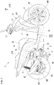
Fig. 1 is a right side view of a motorcycle according to an embodiment of the present invention. -
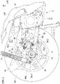
Fig. 2 is a right side view around a rear wheel of the motorcycle. -
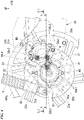
Fig. 3 is a rear view around the rear wheel of the motorcycle. -
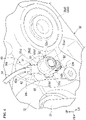
Fig. 4 is a right side view in which a main part ofFig. 2 is enlarged. -
Fig. 5 is a left side view of the main part ofFIG. 2 from an inner side in a vehicle width direction and is a cross-sectional view along line V-V ofFig. 3 . -
Fig. 6 is a perspective view around a sensor mounting part of an auxiliary arm. -
Fig. 7 is a perspective view around the sensor mounting part of the auxiliary arm alone. -
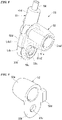
Fig. 8 is a perspective view of a sensor sub-assembly of a wheel speed sensor. -
Fig. 9 is a perspective view of a protective cover for the wheel speed sensor. -
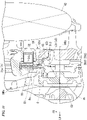
Fig. 10 is a cross-sectional view along line X-X ofFig. 4 . -
Fig. 11 is a cross-sectional view along line XI-XI ofFig. 4 . - Hereinafter, an embodiment of the present invention will be described with reference to the drawings. In the following description, directions such as forward, rearward, left, and right are the same as directions in a vehicle to be described below unless otherwise specified. Also, an arrow FR indicating a forward direction with respect to the vehicle, an arrow LH indicating a leftward direction with respect to the vehicle, an arrow UP indicating an upward direction with respect to the vehicle, and a line CL indicating a vehicle body left-right center are illustrated at suitable positions in the drawings used for the following description.
- As illustrated in
Fig. 1 , a motorcycle (straddle-type vehicle) 1 of the present embodiment includes ahead pipe 13 at a front end portion of a vehicle body frame F. Afront fork 11 that rotatably supports a front wheel WF and asteering handlebar 12 are supported by thehead pipe 13 to be steerable. At a lower portion of the vehicle body frame F, a lower side of a front portion of a swing-type power unit (hereinafter referred to as a power unit U) is supported to be vertically swingable. Themotorcycle 1 is a straddle-type vehicle of a unit swing type including the power unit U in which an engine (internal combustion engine) E serving as a prime mover and a rear wheel WR serving as a drive wheel swing integrally with respect to the vehicle body frame F (vehicle main body). - Referring also to
Figs. 2 and3 , the power unit U is an integrated unit in which the engine E serving as a prime mover of themotorcycle 1 is disposed at a portion in front, and a transmission M for shifting an output from the engine E is disposed on a left side of a rear portion. An axle (rear wheel axle) AR of the rear wheel WR serving as a drive wheel is supported at a rear portion of the transmission M. A front portion of the power unit U is supported by a support part of the vehicle body frame F to be vertically swingable via a suspension link or the like. A rear end portion of the power unit U is supported by a rear end portion of the vehicle body frame F via a pair of left and rightrear cushions 9 which are shock absorbers. In the drawing, reference sign WRa indicates a wheel of the rear wheel WR, and reference sign WRc indicates a central axis of the rear wheel WR (axle AR). - As illustrated in
Fig. 1 , the vehicle body frame F includes adown frame 14 extending downward and rearward from thehead pipe 13, alower frame 15 extending rearward from a lower end portion of thedown frame 14, and arear frame 16 extending rearward and upward from a rear end portion of thelower frame 15. A vicinity of the vehicle body frame F is covered with avehicle body cover 27. Aseat 28 having front and rear seating surfaces for a rider to be seated is supported above a rear portion of thevehicle body cover 27. - The
vehicle body cover 27 includes astep floor 29 on which a driver seated on theseat 28 places his/her feet, afront body 27F which is continuous with the front of thestep floor 29, and arear body 27R which is continuous with the rear of thestep floor 29. A straddling space that allows the rider to easily straddle the vehicle body is formed above thestep floor 29 and between theseat 28 and thesteering wheel 12.Reference sign 19 in the drawing indicates a folding step for a passenger. - The
step floor 29 has, for example, a flat shape over a left-right width of a low floor part of the vehicle body and forms a substantially horizontal upper surface (floor surface 29a) of the low floor part. Themotorcycle 1 is a scooter-type vehicle having thestep floor 29 on which the driver places his/her feet. Further, it may be configured to include a center tunnel extending in a front-rear direction at a left-right center of thestep floor 29. - The engine E is a four-stroke single cylinder engine in which a rotation center axis of a crankshaft (not illustrated) extends in a left-right direction (vehicle width direction) and includes a
cylinder part 22 that protrudes from a front end portion of acrankcase 21 toward the front substantially horizontally (slightly inclined upward to the front, in detail). - Referring to
Fig. 3 , atransmission case 35 as a rear arm protruding to the left and then extending to the rear is connected to a left rear side of thecrankcase 21. The transmission M is housed in thetransmission case 35. - The transmission M is a belt-type continuously variable transmission housed in a length direction of the
transmission case 35 in a side view. The rear wheel axle AR (which is also an output shaft) protrudes on a right side of a rear portion of thetransmission case 35, and the rear wheel WR is attached to the rear wheel axle AR to be integrally rotatable. - A front end portion of an
auxiliary arm 38 extending in a front-rear direction is connected to a right side of a rear portion of thecrankcase 21. Theauxiliary arm 38, together with thetransmission case 35, constitutes a rear arm (swing arm) that supports the rear wheel WR. Theauxiliary arm 38 supports a right end portion of the rear wheel axle AR at a rear end portion. Theauxiliary arm 38, together with thetransmission case 35, constitutes the swing arm that supports the rear wheel WR. Lower end portions of the pair of left and rightrear cushions 9 are connected to the rear end portions of thetransmission case 35 and theauxiliary arm 38. Upper end portions of the left and rightrear cushions 9 are connected to rear end portions of the left and right rear frames 16. - A
central opening 38a penetrating in the vehicle width direction is formed in theauxiliary arm 38. Hollowing out is performed on an inner side of theauxiliary arm 38 in the vehicle width direction leaving a reinforcingrib 38b. Acaliper 31 of a rear wheel brake BR is attached to an inner side in the vehicle width direction of a rear portion of theauxiliary arm 38 via acaliper bracket 32. In the drawing, reference sign 38c1 indicates a caliper bracket attachment part (chassis component attachment part) for attaching thecaliper bracket 32 in theauxiliary arm 38, reference sign 38c2 indicates a caliper attachment part (chassis component attachment part) for attaching thecaliper 31 in thecaliper bracket 32, and reference sign 38c3 indicates a cushion connection part (chassis component attachment part) for connecting a lower end portion of therear cushion 9 in theauxiliary arm 38. For convenience of illustration, reference signs of the attachment parts 38c1, 38c2, and 38c3 are denoted at positions of fastening bolts. - A muffler (silencer) 42 connected to an exhaust pipe 41 of the engine E is disposed on a right side of the rear wheel WR. An
air cleaner 25 supported by an upper portion of thetransmission case 35 is disposed on a left side of the rear wheel WR. - The
motorcycle 1 employs an anti-lock brake system (hereinafter referred to as "ABS") that feeds back a slip ratio of a wheel to control a braking force on the wheel. The ABS of themotorcycle 1 includes wheel speed sensors provided in the front and rear wheels WF and WR and controls brake hydraulic pressures of the front and rear wheels WF and WR by comparing outputs of the wheel speed sensors with each other. - The
motorcycle 1 includes a front wheel brake BF and a rear wheel brake BR which are hydraulic disc brakes. - The rear wheel brake BR includes a
brake disc 33 that rotates integrally with the rear wheel WR, and acaliper 31 that sandwiches and presses thebrake disc 33 to generate a frictional braking force. The front wheel brake BF has the same configuration. - Each of the calipers of the front and rear brakes is connected to a master cylinder via an ABS modulator (not illustrated). A brake operator such as a brake lever is connected to the master cylinder. At the time of braking the vehicle, the driver operates the brake operator to generate a hydraulic pressure in the master cylinder, and the hydraulic pressure is supplied to the front and rear calipers via the ABS modulator. Thereby, the front and rear calipers sandwich and press the brake discs to brake rotation of the front and rear wheels WF and WR.
- The ABS modulator can detect that the front and rear wheels WF and WR are about to fall into a lock state from detection information of
wheel speed sensors 51 at the time of braking the vehicle. When the ABS modulator detects a likelihood of locking of the front and rear wheels WF and WR, it performs ABS control (anti-lock brake control) for the front and rear brakes. The ABS control is performed by reducing or increasing a brake hydraulic pressure supplied to the caliper, or keeping it constant. - As illustrated in
Figs. 4 ,10 and11 , the rear wheel brake BR is disposed on a right portion of the rear wheel WR. Thebrake disc 33 of the rear wheel brake BR has an annular disc shape with an opening at a center portion. On an inner circumferential side of thebrake disc 33, a plurality offastening flanges 33a that allow thebrake disc 33 to be fastened to awheel hub 8 of the rear wheel WR are provided to protrude. The plurality offastening flanges 33a are disposed to be aligned at regular intervals in a disc circumferential direction (circumferential direction of the rear wheel WR). A plurality ofdisc attachment parts 8a for attaching thefastening flanges 33a of thebrake disc 33 are provided in thewheel hub 8. Each of thedisc attachment parts 8a allows a fastening bolt B1 in the vehicle width direction to be detachably attached from an outer side in the vehicle width direction. Afastening flange 55a of asensor ring 55 is jointly fastened and fixed to eachdisc attachment part 8a together with thefastening flange 33a of thebrake disc 33. - Referring to
Fig. 4 , thecaliper 31 of the rear wheel brake BR is supported by theauxiliary arm 38 via thecaliper bracket 32. Thecaliper 31 is a floating type (one-side push type) that is slidably supported by a specified amount in an axle direction (a direction along the axle, a vehicle width direction) with respect to thecaliper bracket 32 fixed to theauxiliary arm 38. A pair of upper and lower caliper bracket attachment parts 38c1 for fastening thecaliper bracket 32 are provided on an inner side in the vehicle width direction of the rear portion of theauxiliary arm 38. - The
caliper 31 includes acaliper body 31a in a mode of straddling thebrake disc 33 in the axle direction, and a pair ofbrake pads 31b that are held on an inner side of thecaliper body 31a for sandwiching and pressing thebrake disc 33. A cylinder and a piston (reference signs are omitted for both) in the axle direction are provided on an outer side of thecaliper body 31a in the axle direction. In thecaliper body 31a, when a hydraulic pressure is supplied to an oil chamber in the cylinder and the piston moves inward in the axle direction, thebrake pad 31b on an outer side in the axle direction presses an outer surface of thebrake disc 33, and a reaction force thereby causes thecaliper body 31a to slide outward in the axle direction so that thebrake pad 31b on an inner side in the axle direction presses an inner surface of thebrake disc 33. Thereby, both thebrake pads 31b sandwich and press thebrake disc 33 to brake the rear wheel WR. Further, thecaliper 31 may be of an opposed piston type. - As illustrated in
Figs. 4 to 6 and8, thewheel speed sensor 51 for detecting a rotation speed of the rear wheel WR is mounted on the inner side of theauxiliary arm 38 in the vehicle width direction. The plate-shaped sensor ring (pulsar ring) 55 that rotates integrally with the rear wheel WR is attached to a right end portion of thewheel hub 8. - The
wheel speed sensor 51 is directly mounted on the auxiliary arm 38 (wheel support member), but the present invention is not limited thereto. For example, thewheel speed sensor 51 may be indirectly mounted on theauxiliary arm 38 via a different member. For example, thewheel speed sensor 51 may be mounted on a member on a non-rotating side with respect to the rear wheel WR similarly to theauxiliary arm 38. - The
wheel speed sensor 51 has a pickup coil that generates a pulse signal in accordance with rotation of thesensor ring 55. The pickup coil generates a pulse signal due to a change in magnetic flux according to rotation of a pickup hole 55b1 of thesensor ring 55. Thewheel speed sensor 51 outputs the pulse signal generated by the pickup coil to the control unit. Asensor cable 54 is drawn out from thewheel speed sensor 51. Thesensor cable 54 is connected to a specified control unit. For example, the wheel speed information detected by thewheel speed sensor 51 is used for controlling the ABS, a traction control system, or the like. - The
wheel speed sensor 51 includes acolumnar detection unit 51a and aholder part 51b integrally provided on one end side of thedetection unit 51a in an axial direction. Theholder part 51b has an oval shape when viewed in the axial direction of thedetection unit 51a. Thedetection unit 51a is disposed on one side of theholder part 51b in a major axis direction, and abolt insertion hole 51c is disposed on the other side of theholder part 51b in the major axis direction. Thedetection unit 51a accommodates the pickup coil in a case that forms an outer shape thereof. The case of thedetection unit 51a and theholder part 51b are integrally formed of a resin or the like. The other end of thedetection unit 51a in the axial direction is a detection end facing thesensor ring 55. A fastening bolt B2 for fastening and fixing thewheel speed sensor 51 to asensor mounting part 60 of theauxiliary arm 38 is inserted into thebolt insertion hole 51c. - A one side edge 51b1 of the
holder part 51b in a minor axis direction is a first engaged part with which a holdingclaw part 52d provided on a side edge of a base end portion of aprotective cover 52 to be described later comes into contact. - The other side edge 51b2 of the
holder part 51b in the minor axis direction is a second engaged part that comes into contact with an upright wall part (positioning part) 61 provided on an inner side of theauxiliary arm 38 in the vehicle width direction. - A cylindrical wiring lead-out
part 51d extending in the major axis direction protrudes from one side end of theholder part 51b in the major axis direction. The wiring lead-outpart 51d is integrally formed with theholder part 51b. Thesensor cable 54 serving as a signal line is drawn out from a distal end of the wiring lead-outpart 51d and is routed through the vehicle body side. - The
wheel speed sensor 51 is mounted on theauxiliary arm 38 that is on a non-rotating side with respect to the rear wheel WR. Thewheel speed sensor 51 is mounted on the inner side in the vehicle width direction of the rear portion of theauxiliary arm 38. Thereby, thewheel speed sensor 51 and thesensor ring 55 disposed on the inner side in the vehicle width direction of the rear portion of theauxiliary arm 38 are close to each other in the vehicle width direction, and installation of thewheel speed sensor 51 is facilitated. - As illustrated in
Figs. 4 ,10 , and11 , thesensor ring 55 includes a detectedpart 55b having an annular shape that is coaxial with the rear wheel WR, and a plurality offastening flanges 55a that extend to an outer circumferential side of the detectedpart 55b. Thesensor ring 55 is formed in a flat plate shape including the detectedpart 55b and thefastening flanges 55a. The detectedpart 55b is provided to have a diameter smaller than that of thewheel hub 8 when viewed in the axle direction. A plurality ofpickup holes 55bpart 55b at regular intervals in a ring circumferential direction. The detection end of thewheel speed sensor 51 faces the detectedpart 55b from an outer side in the axle direction. The detectedpart 55b is disposed on an outer side in the axle direction with respect to the outer surface of thebrake disc 33. The plurality offastening flanges 55a are disposed to be aligned at regular intervals in the ring circumferential direction. Thefastening flanges 55a respectively overlap the plurality offastening flanges 33a of thebrake disc 33 from an outer side in the vehicle width direction. Each of thefastening flanges 55a is jointly fastened and fixed to thewheel hub 8 together with each of thefastening flanges 33a of thebrake disc 33. - As illustrated in
Figs. 5 ,6 ,8, and 9 , theprotective cover 52 is attached to thewheel speed sensor 51. Theprotective cover 52 includes acylindrical cover part 52a that covers thedetection unit 51a inserted therein, and anextension part 52b that extends in a radial direction from a base end side of thecover part 52a in the axial direction. Abolt insertion hole 52c through which the fastening bolt B2 is inserted is formed in theextension part 52b. Although theprotective cover 52 is made of a metal, it may be integrally formed of a resin or the like (including an elastic material such as rubber). Theprotective cover 52 is in a state in which theextension part 52b overlaps the other side of theholder part 51b in the major axis direction with thedetection unit 51a inserted in thecover part 52a. In this state, the fastening bolt B2 is inserted into thebolt insertion holes extension part 52b and theholder part 51b. The fastening bolt B2 is screwed and fastened to afastening boss 63 of thesensor mounting part 60 on an inner side of theauxiliary arm 38 in the vehicle width direction. Thereby, thewheel speed sensor 51 and theprotective cover 52 are jointly fastened and fixed to theauxiliary arm 38. Hereinafter, a sub-assembly in which theprotective cover 52 is attached to thewheel speed sensor 51 may be referred to as asensor sub-assembly 53. - A holding
claw part 52d that is in contact with the one side edge 51b1 of theholder part 51b in the minor axis direction is provided on one side edge of the base end portion of theprotective cover 52 in a state in which it is assembled to thewheel speed sensor 51. The holdingclaw part 52d is provided across thecover part 52a and theextension part 52b of theprotective cover 52. The holdingclaw part 52d has a rectangular parallelepiped shape that is long along the one side edge 51b1 of theholder part 51b. The holdingclaw part 52d produces the following actions when thesensor sub-assembly 53 is mounted on theauxiliary arm 38. When theprotective cover 52 jointly rotates in a fastening direction (a clockwise direction, a direction of the arrow CW in the drawing) of the fastening bolt B2, the holdingclaw part 52d is brought into contact with and pressed against the one side edge 51b1 of theholder part 51b of thewheel speed sensor 51. Thewheel speed sensor 51 stops rotation when the other side edge 51b2 of theholder part 51b is brought into contact with theupright wall part 61. Therefore, when the holdingclaw part 52d is pressed against the one side edge 51b1 of theholder part 51b, theholder part 51b is sandwiched between the holdingclaw part 52d and theupright wall part 61. The dimension L inFig. 10 indicates a region in which the holdingclaw part 52d and theupright wall part 61 overlap in the vehicle width direction. - As illustrated in
Figs. 5 to 7 , thesensor mounting part 60 for mounting thesensor sub-assembly 53 is provided on the inner side in the vehicle width direction of the rear portion of theauxiliary arm 38. Thesensor mounting part 60 is disposed in front of anaxle insertion part 38d in which the rear wheel axle AR is inserted and supported in theauxiliary arm 38. Thesensor mounting part 60 includes thefastening boss 63 for fastening thesensor sub-assembly 53, and also includes theupright wall part 61 and a protrudingpart 62 for positioning the sensor sub-assembly 53 (particularly the wheel speed sensor 51). - The
axle insertion part 38d includes a cylindrical wall 38d1 for holding a bearing or the like. Thefastening boss 63 is connected and supported on a front end side of the cylindrical wall 38d1 via a connection wall 38d2 extending outward in the radial direction. Thefastening boss 63 is disposed to be shifted downward with respect to the connection wall 38d2. Theupright wall part 61 that rises inward in the vehicle width direction along the vehicle width direction is provided at a distal end portion on an inner side of the connection wall 38d2 in the vehicle width direction. Theupright wall part 61 rises vertically from a distal end surface (fastening seat surface) 63a on an inner side of thefastening boss 63 in the vehicle width direction. Theupright wall part 61 is brought into contact with the other side edge 51b2 of theholder part 51b in the fastening direction CW of the fastening bolt B2. Thereby, rotation of thewheel speed sensor 51 stops in fastening the fastening bolt B2. - The protruding
part 62 is integrally formed with the reinforcingrib 38b exposed to an inner side of theauxiliary arm 38 in the vehicle width direction above theupright wall part 61. Aconcave part 62a that is curved to follow an outer circumferential surface of the wiring lead-outpart 51d of thewheel speed sensor 51 is formed at a distal end portion of the protrudingpart 62 on an inner side in the vehicle width direction. Theconcave part 62a surrounds a range extending from an outer side of the wiring lead-outpart 51d in the vehicle width direction to the front thereof when thewheel speed sensor 51 is mounted on theauxiliary arm 38. The front of the wiring lead-outpart 51d is a side in an opposite direction (a fastening release direction, a counterclockwise direction) to the fastening direction CW of the fastening bolt B2. Thereby, when thewheel speed sensor 51 is removed from theauxiliary arm 38, rotation of thewheel speed sensor 51 in the opposite direction is restricted by the protrudingpart 62. - Further, in the present embodiment, the
sensor mounting part 60 and thesensor sub-assembly 53 are disposed on the inner side in the vehicle width direction of the rear portion of theauxiliary arm 38. Also, at least a part (entire in the embodiment) of thesensor mounting part 60 and thesensor sub-assembly 53 is disposed in a triangular region N surrounded by connecting an axis of the rear wheel axle AR and axes of the fastening bolts of the upper and lower caliper bracket attachment parts 38c1 of theauxiliary arm 38 in a side view. Thereby, thewheel speed sensor 51 is unlikely to be visually noticeable from the outside in the vehicle width direction, and an influence on an external appearance can be minimized. In the present embodiment, the caliper bracket attachment part 38c1 and the caliper attachment part 38c2 may be inclusively referred to as caliper attachment parts (chassis component attachment parts) 38c1 and 38c2. - Also, when the
wheel speed sensor 51 is mounted from an outer side of theauxiliary arm 38 in the vehicle width direction, the rear wheel axle AR and the upper and lower caliper attachment parts 38c1 and 38c2 make it easy to find thesensor mounting part 60. That is, a position of thesensor mounting part 60 is easily found by tactual sense on the basis of the presence of the rear wheel axle AR and the upper and lower caliper attachment parts 38c1 and 38c2. Therefore, assembly of thesensor sub-assembly 53 can be easily performed. - Also, if a procedure for mounting the
sensor sub-assembly 53 before attaching thecaliper bracket 32 is employed, thesensor sub-assembly 53 can be more easily mounted. Also, since thecaliper bracket 32 is disposed in front of thesensor sub-assembly 53 after thesensor sub-assembly 53 is mounted, thesensor sub-assembly 53 can be better protected. - Also, the positioning part (the upright wall part 61) is provided adjacent to the rear of a sensor fastening part (the fastening boss 63) for fastening the
sensor sub-assembly 53 on the inner side in the vehicle width direction of the rear portion of theauxiliary arm 38. Theupright wall part 61 performs positioning of the sensor sub-assembly 53 (particularly the wheel speed sensor 51) in a rotation direction (fastening direction) with respect to the fastening bolt B2. Thereby, when thesensor sub-assembly 53 is disposed in thesensor mounting part 60, the positioning of thesensor sub-assembly 53 is easily and accurately performed. Also, joint rotation of thesensor sub-assembly 53 is restricted even when the bolt is fastened. Therefore, thesensor sub-assembly 53 can be more easily mounted. - Further, a second positioning part (the protruding part 62) is provided apart from the
fastening boss 63 and theupright wall part 61 on the inner side in the vehicle width direction of the rear portion of theauxiliary arm 38. The protrudingpart 62 performs positioning of the sensor sub-assembly 53 (particularly the wheel speed sensor 51) in a rotation direction (fastening release direction) with respect to the fastening bolt B2. This also makes it easy and accurate to position thesensor sub-assembly 53 when thesensor sub-assembly 53 is disposed in thesensor mounting part 60. Also, the joint rotation of thesensor sub-assembly 53 is restricted even when bolt fastening is released. Therefore, thesensor sub-assembly 53 can be mounted and removed more easily. - The protruding
part 62 includes theconcave part 62a that is curved to follow the outer circumference of the wiring lead-outpart 51d of thewheel speed sensor 51 and engages with the wiring lead-outpart 51d. Thereby, positioning of thesensor sub-assembly 53 is easily and accurately performed, and a load on the wiring lead-outpart 51d can be suppressed even when the joint rotation of thesensor sub-assembly 53 is restricted. - The
wheel speed sensor 51 is covered with aprotective cover 52 made of a resin, and is fastened and fixed to theauxiliary arm 38 together with theprotective cover 52. Thereby, thewheel speed sensor 51 can be better protected, and theprotective cover 52 can be jointly fastened and fixed with thewheel speed sensor 51 to facilitate attachment and detachment. - When the
wheel speed sensor 51 jointly rotates in the fastening direction CW of the fastening bolt B2 at the time of fastening thesensor sub-assembly 53, the one side edge 51b1 of theholder part 51b of thewheel speed sensor 51 comes into contact with theupright wall part 61. In this state, when theprotective cover 52 further jointly rotates, the holdingclaw part 52d of theprotective cover 52 is brought into contact with and presses the other side edge 51b2 of theholder part 51b. As a result, after the fastening bolt B2 is fastened, theholder part 51b of thewheel speed sensor 51 is sandwiched between the holdingclaw part 52d of theprotective cover 52 and theupright wall part 61 of theauxiliary arm 38. In this state, since thewheel speed sensor 51 is mounted on theauxiliary arm 38 together with theprotective cover 52, an accuracy of the mounting position of thewheel speed sensor 51 can be improved. - Further, the present invention is not limited to the above-described embodiment, and for example, the present invention has been applied to the mounting structure of the
wheel speed sensor 51 of the rear wheel WR in the embodiment, but the present invention may be applied to a mounting structure of a wheel speed sensor of the front wheel WF. In this case, the wheel support member is a front wheel support member such as thefront fork 11 instead of the rear wheel support member such as the auxiliary arm 38 (swing arm). The wheel support member is not limited to one that is supported by the vehicle body frame F but may be one supported by the engine, the transmission, or the like mounted on the vehicle body. Also, thecaliper 31 may be configured to be directly attached to the wheel support member without interposing thecaliper bracket 32 or the like. Also, a disposition of thecaliper 31 is not limited to the front of the axle, and may be above, below, or behind the axle. The chassis component attachment part that defines a disposition region of thewheel speed sensor 51 is not limited to the caliper attachment parts 38c1 and 38c2, and may be an attachment part for a suspension component or a steering component. - The straddle-type vehicle described above includes general vehicles on which a driver straddles a vehicle body to ride, including not only motorcycles (including motorized bicycles and scooter type vehicles) but also three-wheeled vehicles (including vehicles with two front wheels and one rear wheel as well as vehicles with one front wheel and two rear wheels) or four-wheeled vehicles. Further, vehicles having an electric motor as a prime mover are also included therein.
- The configurations in the embodiment described above are examples of the present invention, and various changes can be made within a range not departing from the gist of the present invention such as replacing the components of the embodiment with well-known components.
-
- 1: Motorcycle (straddle-type vehicle)
- 38: Auxiliary arm (wheel support member)
- 38c1: Caliper bracket attachment part (chassis component attachment part)
- 38c2: Caliper attachment part (chassis component attachment part)
- 51: Wheel speed sensor
- 51d: Wiring lead-out part (engaged part)
- 52: Protective cover (protective member)
- 52d: Holding claw part (holding part)
- 55: Sensor ring
- 60: Sensor mounting part
- 61: Upright wall part (positioning part)
- 62: Protruding part (second positioning part)
- 62a: Concave part (surrounding part)
- 63: Fastening boss (sensor fastening part)
- F: Vehicle body frame (vehicle body)
- WR: Rear wheel (wheel)
- AR: Axle
- N: Region
Claims (6)
- A wheel speed sensor mounting structure comprising:a wheel support member (38) supported by a vehicle body (F) and configured to support a wheel (WR); anda wheel speed sensor (51) detecting a rotation speed of the wheel (WR), whereinthe wheel speed sensor (51) is disposed on an inner side of the wheel support member (38) in a vehicle width direction and is disposed in a region (N) surrounded by an axle (AR) of the wheel (WR) and chassis component attachment parts (38c1 and 38c2) of the wheel support member (38) in a side view.
- The wheel speed sensor mounting structure according to claim 1, further comprising a positioning part (61) provided on the inner side of the wheel support member (38) in the vehicle width direction, adjacent to a sensor fastening part (63) which fastens the wheel speed sensor (51), and used for positioning of the wheel speed sensor (51).
- The wheel speed sensor mounting structure according to claim 2, further comprising a second positioning part (62) provided on the inner side of the wheel support member (38) in the vehicle width direction, separated from the sensor fastening part (63) and the positioning part (61), and used for positioning of the wheel speed sensor (51) in a rotational direction with respect to a center of the fastening part.
- The wheel speed sensor mounting structure according to claim 3, wherein the second positioning part (62) includes a surrounding part (62a) formed to follow an engaged part (51d) at a portion engaging with the engaged part (51d) of the wheel speed sensor (51).
- The wheel speed sensor mounting structure according to any one of claims 1 to 4, wherein the wheel speed sensor (51) is covered with a protective member (52) and fastened to the wheel support member (38) together with the protective member (52).
- The wheel speed sensor mounting structure according to claim 5, wherein the wheel speed sensor (51) is mounted on the wheel support member (38) in a state in which it is sandwiched between a holding part (52d) provided in the protective member (52) and the positioning part (61) provided on the inner side of the wheel support member (38) in the vehicle width direction.
Applications Claiming Priority (1)
| Application Number | Priority Date | Filing Date | Title |
|---|---|---|---|
| PCT/JP2019/034735 WO2021044542A1 (en) | 2019-09-04 | 2019-09-04 | Wheel speed sensor mounting structure |
Publications (3)
| Publication Number | Publication Date |
|---|---|
| EP4026762A1 true EP4026762A1 (en) | 2022-07-13 |
| EP4026762A4 EP4026762A4 (en) | 2022-08-17 |
| EP4026762B1 EP4026762B1 (en) | 2024-02-21 |
Family
ID=74852192
Family Applications (1)
| Application Number | Title | Priority Date | Filing Date |
|---|---|---|---|
| EP19944099.1A Active EP4026762B1 (en) | 2019-09-04 | 2019-09-04 | Wheel speed sensor mounting structure |
Country Status (3)
| Country | Link |
|---|---|
| EP (1) | EP4026762B1 (en) |
| JP (1) | JP7253627B2 (en) |
| WO (1) | WO2021044542A1 (en) |
Family Cites Families (7)
| Publication number | Priority date | Publication date | Assignee | Title |
|---|---|---|---|---|
| JP2001165949A (en) * | 1999-09-30 | 2001-06-22 | Honda Motor Co Ltd | Wheel speed detector |
| JP4819455B2 (en) * | 2005-09-15 | 2011-11-24 | 川崎重工業株式会社 | VEHICLE ROTATION DETECTION DEVICE AND MOTORCYCLE WITH THE SAME |
| JP4856495B2 (en) * | 2006-08-22 | 2012-01-18 | 本田技研工業株式会社 | Motorcycle |
| JP2014136542A (en) | 2013-01-18 | 2014-07-28 | Honda Motor Co Ltd | Motor cycle |
| EP3279067B1 (en) | 2015-03-31 | 2020-02-19 | Honda Motor Co., Ltd. | Support structure for wheel speed sensor |
| ES2716759T3 (en) * | 2016-12-05 | 2019-06-14 | Yamaha Motor Co Ltd | Saddle riding vehicle |
| JP6926216B2 (en) | 2017-09-27 | 2021-08-25 | 本田技研工業株式会社 | Front structure of saddle-riding vehicle |
-
2019
- 2019-09-04 EP EP19944099.1A patent/EP4026762B1/en active Active
- 2019-09-04 WO PCT/JP2019/034735 patent/WO2021044542A1/en unknown
- 2019-09-04 JP JP2021543858A patent/JP7253627B2/en active Active
Also Published As
| Publication number | Publication date |
|---|---|
| JP7253627B2 (en) | 2023-04-06 |
| EP4026762A4 (en) | 2022-08-17 |
| WO2021044542A1 (en) | 2021-03-11 |
| EP4026762B1 (en) | 2024-02-21 |
| JPWO2021044542A1 (en) | 2021-03-11 |
Similar Documents
| Publication | Publication Date | Title |
|---|---|---|
| JP5783994B2 (en) | Wheel speed sensor ring mounting structure | |
| US9199687B2 (en) | Saddle-type vehicle | |
| JP6355290B2 (en) | Sensor unit mounting structure for saddle riding type vehicles | |
| JP2015199477A (en) | Saddle-riding type vehicle | |
| US8381863B2 (en) | Connection structure arrangement between a frame member and an engine of a saddle-type vehicle, and vehicle incorporating same | |
| EP2404796B1 (en) | Motorcycle | |
| US11345430B2 (en) | Front fork lower portion structure of saddle riding vehicle | |
| JP4298811B2 (en) | Anti-lock brake device for scooter | |
| EP4026762B1 (en) | Wheel speed sensor mounting structure | |
| EP3225526B1 (en) | Saddle-riding-type vehicle cable support structure | |
| JP6926216B2 (en) | Front structure of saddle-riding vehicle | |
| EP0990582B1 (en) | Front wheel suspension assembly for a motorcycle | |
| JP6364664B2 (en) | Sensor mounting structure for saddle riding type vehicles | |
| CN109278909B (en) | Saddle-ride type vehicle | |
| EP2891600B1 (en) | Two-Wheeled Automobile | |
| JP6966985B2 (en) | Wheel cover structure | |
| JP6268554B2 (en) | Holding structure for saddle-ride type vehicle | |
| JP6994583B2 (en) | Wheel structure | |
| WO2023139986A1 (en) | Brake disk | |
| WO2020202198A1 (en) | Multi-purpose swing arm of vehicle | |
| JP2021098473A (en) | Saddle-riding type vehicle |
Legal Events
| Date | Code | Title | Description |
|---|---|---|---|
| STAA | Information on the status of an ep patent application or granted ep patent |
Free format text: STATUS: THE INTERNATIONAL PUBLICATION HAS BEEN MADE |
|
| PUAI | Public reference made under article 153(3) epc to a published international application that has entered the european phase |
Free format text: ORIGINAL CODE: 0009012 |
|
| STAA | Information on the status of an ep patent application or granted ep patent |
Free format text: STATUS: REQUEST FOR EXAMINATION WAS MADE |
|
| 17P | Request for examination filed |
Effective date: 20220308 |
|
| AK | Designated contracting states |
Kind code of ref document: A1 Designated state(s): AL AT BE BG CH CY CZ DE DK EE ES FI FR GB GR HR HU IE IS IT LI LT LU LV MC MK MT NL NO PL PT RO RS SE SI SK SM TR |
|
| A4 | Supplementary search report drawn up and despatched |
Effective date: 20220714 |
|
| RIC1 | Information provided on ipc code assigned before grant |
Ipc: B62J 45/413 20200101ALI20220708BHEP Ipc: B60T 8/32 20060101ALI20220708BHEP Ipc: B62J 11/00 20200101ALI20220708BHEP Ipc: B62J 99/00 20200101AFI20220708BHEP |
|
| DAV | Request for validation of the european patent (deleted) | ||
| DAX | Request for extension of the european patent (deleted) | ||
| STAA | Information on the status of an ep patent application or granted ep patent |
Free format text: STATUS: EXAMINATION IS IN PROGRESS |
|
| 17Q | First examination report despatched |
Effective date: 20230330 |
|
| REG | Reference to a national code |
Ref country code: DE Ref legal event code: R079 Ref document number: 602019047151 Country of ref document: DE Free format text: PREVIOUS MAIN CLASS: B62J0099000000 Ipc: B62K0019380000 Ref country code: DE Ref legal event code: R079 Free format text: PREVIOUS MAIN CLASS: B62J0099000000 Ipc: B62K0019380000 |
|
| RIC1 | Information provided on ipc code assigned before grant |
Ipc: G01P 1/02 20060101ALI20230906BHEP Ipc: B60T 8/32 20060101ALI20230906BHEP Ipc: G01P 3/488 20060101ALI20230906BHEP Ipc: B62J 45/413 20200101ALI20230906BHEP Ipc: B62J 45/423 20200101ALI20230906BHEP Ipc: B62K 19/38 20060101AFI20230906BHEP |
|
| GRAP | Despatch of communication of intention to grant a patent |
Free format text: ORIGINAL CODE: EPIDOSNIGR1 |
|
| STAA | Information on the status of an ep patent application or granted ep patent |
Free format text: STATUS: GRANT OF PATENT IS INTENDED |
|
| INTG | Intention to grant announced |
Effective date: 20231017 |
|
| GRAS | Grant fee paid |
Free format text: ORIGINAL CODE: EPIDOSNIGR3 |
|
| GRAA | (expected) grant |
Free format text: ORIGINAL CODE: 0009210 |
|
| STAA | Information on the status of an ep patent application or granted ep patent |
Free format text: STATUS: THE PATENT HAS BEEN GRANTED |
|
| AK | Designated contracting states |
Kind code of ref document: B1 Designated state(s): AL AT BE BG CH CY CZ DE DK EE ES FI FR GB GR HR HU IE IS IT LI LT LU LV MC MK MT NL NO PL PT RO RS SE SI SK SM TR |
|
| REG | Reference to a national code |
Ref country code: GB Ref legal event code: FG4D |
|
| REG | Reference to a national code |
Ref country code: CH Ref legal event code: EP |
|
| REG | Reference to a national code |
Ref country code: DE Ref legal event code: R096 Ref document number: 602019047151 Country of ref document: DE |
|
| REG | Reference to a national code |
Ref country code: IE Ref legal event code: FG4D |