EP4026646A1 - Stirring pin, friction stir welding tool, and machine tool - Google Patents
Stirring pin, friction stir welding tool, and machine tool Download PDFInfo
- Publication number
- EP4026646A1 EP4026646A1 EP19948460.1A EP19948460A EP4026646A1 EP 4026646 A1 EP4026646 A1 EP 4026646A1 EP 19948460 A EP19948460 A EP 19948460A EP 4026646 A1 EP4026646 A1 EP 4026646A1
- Authority
- EP
- European Patent Office
- Prior art keywords
- pin
- stir
- ring
- shaped receiving
- base end
- Prior art date
- Legal status (The legal status is an assumption and is not a legal conclusion. Google has not performed a legal analysis and makes no representation as to the accuracy of the status listed.)
- Granted
Links
- 238000003756 stirring Methods 0.000 title claims abstract description 314
- 238000003466 welding Methods 0.000 title claims description 88
- 239000000463 material Substances 0.000 claims abstract description 84
- 239000002699 waste material Substances 0.000 claims abstract description 78
- 238000003825 pressing Methods 0.000 claims description 7
- 230000004048 modification Effects 0.000 description 10
- 238000012986 modification Methods 0.000 description 10
- 239000002184 metal Substances 0.000 description 8
- 229910052751 metal Inorganic materials 0.000 description 8
- 230000000694 effects Effects 0.000 description 5
- 238000003754 machining Methods 0.000 description 5
- 239000000523 sample Substances 0.000 description 5
- 230000006870 function Effects 0.000 description 3
- 239000010814 metallic waste Substances 0.000 description 3
- 238000003860 storage Methods 0.000 description 3
- 230000000994 depressogenic effect Effects 0.000 description 2
- 238000005304 joining Methods 0.000 description 2
- 150000002739 metals Chemical class 0.000 description 2
- 238000000034 method Methods 0.000 description 2
- 230000000295 complement effect Effects 0.000 description 1
- 238000005520 cutting process Methods 0.000 description 1
- 238000007599 discharging Methods 0.000 description 1
- 238000005516 engineering process Methods 0.000 description 1
- 238000000227 grinding Methods 0.000 description 1
- 239000007769 metal material Substances 0.000 description 1
- 229910052755 nonmetal Inorganic materials 0.000 description 1
- 238000013021 overheating Methods 0.000 description 1
- 239000011347 resin Substances 0.000 description 1
- 229920005989 resin Polymers 0.000 description 1
- 239000012257 stirred material Substances 0.000 description 1
Images


Classifications
-
- B—PERFORMING OPERATIONS; TRANSPORTING
- B23—MACHINE TOOLS; METAL-WORKING NOT OTHERWISE PROVIDED FOR
- B23K—SOLDERING OR UNSOLDERING; WELDING; CLADDING OR PLATING BY SOLDERING OR WELDING; CUTTING BY APPLYING HEAT LOCALLY, e.g. FLAME CUTTING; WORKING BY LASER BEAM
- B23K20/00—Non-electric welding by applying impact or other pressure, with or without the application of heat, e.g. cladding or plating
- B23K20/12—Non-electric welding by applying impact or other pressure, with or without the application of heat, e.g. cladding or plating the heat being generated by friction; Friction welding
- B23K20/122—Non-electric welding by applying impact or other pressure, with or without the application of heat, e.g. cladding or plating the heat being generated by friction; Friction welding using a non-consumable tool, e.g. friction stir welding
- B23K20/1245—Non-electric welding by applying impact or other pressure, with or without the application of heat, e.g. cladding or plating the heat being generated by friction; Friction welding using a non-consumable tool, e.g. friction stir welding characterised by the apparatus
- B23K20/1255—Tools therefor, e.g. characterised by the shape of the probe
-
- B—PERFORMING OPERATIONS; TRANSPORTING
- B23—MACHINE TOOLS; METAL-WORKING NOT OTHERWISE PROVIDED FOR
- B23K—SOLDERING OR UNSOLDERING; WELDING; CLADDING OR PLATING BY SOLDERING OR WELDING; CUTTING BY APPLYING HEAT LOCALLY, e.g. FLAME CUTTING; WORKING BY LASER BEAM
- B23K20/00—Non-electric welding by applying impact or other pressure, with or without the application of heat, e.g. cladding or plating
- B23K20/12—Non-electric welding by applying impact or other pressure, with or without the application of heat, e.g. cladding or plating the heat being generated by friction; Friction welding
- B23K20/122—Non-electric welding by applying impact or other pressure, with or without the application of heat, e.g. cladding or plating the heat being generated by friction; Friction welding using a non-consumable tool, e.g. friction stir welding
- B23K20/1245—Non-electric welding by applying impact or other pressure, with or without the application of heat, e.g. cladding or plating the heat being generated by friction; Friction welding using a non-consumable tool, e.g. friction stir welding characterised by the apparatus
- B23K20/126—Workpiece support, i.e. backing or clamping
-
- B—PERFORMING OPERATIONS; TRANSPORTING
- B23—MACHINE TOOLS; METAL-WORKING NOT OTHERWISE PROVIDED FOR
- B23K—SOLDERING OR UNSOLDERING; WELDING; CLADDING OR PLATING BY SOLDERING OR WELDING; CUTTING BY APPLYING HEAT LOCALLY, e.g. FLAME CUTTING; WORKING BY LASER BEAM
- B23K20/00—Non-electric welding by applying impact or other pressure, with or without the application of heat, e.g. cladding or plating
- B23K20/26—Auxiliary equipment
Definitions
- the present invention relates to a stir pin, a friction stir welding tool, and a machine tool.
- Friction stir welding (Friction Stir Welding) is known.
- a tool pressed against two workpieces, which are joined objects is rotated to weld the two workpieces together. More specifically, metal workpieces are softened by friction heat generated by the rotation of the tool. The softened metals are guided by the rotation of the tool to flow around the tool. Then, the metals flowing around the tool are solidified, so that the two workpieces are welded together.
- patent literature 1 discloses a friction stir tool.
- the friction stir tool recited in patent literature 1 includes a stir probe and a shoulder.
- the stir probe has a flow-prevention surface that changes the flow direction of a flowing object from the axial direction of the stir probe to its radial direction. Flowing metal is prevented by the flow-prevention surface from flowing farther and accumulates in an annular flowing-object container.
- the stir probe is directly connected to a rotational driving axis.
- Patent literature 2 discloses a friction stir welding tool.
- the friction stir welding tool recited in patent literature 2 includes a stir pin and a housing having a first surface.
- the housing has a discharge hole connecting a container hole formed on the first surface to the outside of the housing (through the discharge hole, excess metal is discharged).
- a stir pin includes: a base end portion holdable by a pin holder; a stirring portion rotatable about a first axis relative to a shoulder member; and an intermediate portion provided between the base end portion and the stirring portion and rotatable about the first axis together with the stirring portion.
- the intermediate portion includes a first portion and a second portion that is provided further in a first direction than the first portion.
- the first direction is defined as a direction from the base end portion toward the stirring portion.
- the first portion includes a protrusion protruding beyond an outer surface of the second portion in a direction away from the first axis. the protrusion has a surface that is pointed in the first direction and defines a ring-shaped receiving surface that receives a material waste generated as a result of a friction stirring.
- a friction stir welding tool includes: a shoulder member having a shoulder surface for pressing a workpiece; and a stir pin rotatable about a first axis relative to the shoulder member.
- the stir pin includes: a base end portion holdable by a pin holder; a stirring portion; and an intermediate portion provided between the base end portion and the stirring portion.
- the intermediate portion includes a first portion and a second portion that is provided further in a first direction than the first portion.
- the first direction is defined as a direction from the base end portion toward the stirring portion.
- the first portion includes a protrusion protruding beyond an outer surface of the second portion in a direction away from the first axis.
- the protrusion has a surface that is pointed in the first direction and that defines a ring-shaped receiving surface that prevents a material waste generated as a result of a friction stirring from attaching to the pin holder.
- a machine tool includes: a friction stir welding tool; a workpiece support member configured to support a workpiece that is a to-be-machined object; a tool support member supporting the friction stir welding tool; a first driver configured to move the tool support member relative to the workpiece support member; a second driver configured to drive a stir pin into rotation; and a controller configured to control the first driver and the second driver.
- the friction stir welding tool includes: a shoulder member having a shoulder surface for pressing the workpiece; the stir pin, the stir pin being rotatable about a first axis relative to the shoulder member; and a pin holder.
- the stir pin includes: a base end portion held by the pin holder; a stirring portion; and an intermediate portion provided between the base end portion and the stirring portion.
- the intermediate portion includes a first portion and a second portion that is provided further in a first direction than the first portion.
- the first direction is defined as a direction from the base end portion toward the stirring portion.
- the first portion includes a protrusion protruding beyond an outer surface of the second portion in a direction away from the first axis.
- the protrusion has a surface that is pointed in the first direction and that defines a ring-shaped receiving surface that prevents a material waste generated as a result of a friction stirring from attaching to the pin holder.
- the embodiments of the present invention provide a stir pin, a friction stir welding tool, and a machine tool that prevent material waste from attaching to a pin holder.
- first direction DR1 is defined as a direction from a base end portion 30 of the stir pin 3 (or a base end portion of the shoulder member 7) toward a stirring portion 37 of the stir pin 3 (or a shoulder surface 72s of the shoulder member 7).
- second direction DR2 is defined as a direction opposite to the first direction DR1. For example, when a leading end portion of the stir pin 3 is pointed downward, the first direction DR1 corresponds to downward direction, and the second direction DR2 corresponds to upward direction.
- machine tool is intended to mean any machine to which a friction stir welding tool is attachable.
- the machine tool may be a combined multi-functional machine tool, which is capable of performing a plurality of different kinds of machining (an example is a machining center).
- An example of the machine tool is a machine capable of cutting, machining, grinding, or joining metal.
- the term "material waste” is intended to mean a piece of material detached from a workpiece as a result of a friction stirring.
- the term "workpiece”, as used herein, can be rephrased as “metal workpiece”, and the term “material waste”, as used herein, can be rephrased as “metal waste”. This, however, does not exclude any configuration in which the friction stir welding tool 100 is used to join non-metal workpieces (for example, resin workpieces) together.
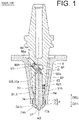
- FIG. 1 is a schematic cross-sectional view of the friction stir welding tool 100A according to the first embodiment, schematically illustrating the friction stir welding tool 100A.
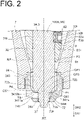
- FIG. 2 is a schematic enlarged cross-sectional view of the friction stir welding tool 100A according to the first embodiment, with part of the friction stir welding tool 100A enlarged.
- FIG. 3 is a schematic cross-sectional view of the stir pin 3A according to the first embodiment, schematically illustrating this stir pin 3A.
- the friction stir welding tool 100A includes the shoulder member 7 and the stir pin 3A.
- the shoulder member 7 has the shoulder surface 72s.
- the shoulder surface 72s is for pressing workpieces, which are to-be-joined objects.
- the shoulder surface 72s is the end face of the shoulder member 7 on the first direction DR1 side.
- the shoulder surface 72s flattens material (of which the workpiece is made) softened by the rotation of the stir pin 3A.
- the shoulder surface 72s is a surface perpendicular to the first direction DR1 (in other words, perpendicular to a first axis AX, described later).
- the shoulder member 7 includes: a first member 70, which has the shoulder surface 72s; and a second member 76.
- the first member 70 is mounted on the second member 76.
- the first member 70 and the second member 76 are threaded to each other.
- the configuration in which the shoulder member 7 includes the first member 70 and the second member 76 makes the frequency by which the second member 76 is replaced lower than the frequency by which the first member 70 is replaced. As a result, the running cost involved in the use of the friction stir welding tool 100A is reduced.
- the shoulder member 7 is an assembly of two piece-parts (70, 76).
- the shoulder member 7 may be made up of a single piece-part or may be an assembly of three or more piece-parts.
- the shoulder member 7 has an internal space SP, which extends along the first direction DR1. In the internal space SP, at least a part of the stir pin 3A is provided. That is, the shoulder member 7 also functions as a housing member for at least a part of the stir pin 3A. In the example illustrated in FIG. 1 , the entirety of the stir pin 3A is provided in the internal space SP of the shoulder member 7.
- the stirring portion 37 of the stir pin 3A is inserted into workpieces with the stirring portion 37 in rotating state.
- the stir pin 3A may also be referred to as a probe. Then, frictional heat generated by the friction between the stir pin 3A and the workpieces makes the material of the workpieces (more specifically, metal material) softened. The softened material is stirred by the rotating stir pin 3A. Then, the stirred material is solidified, and thus the workpieces are joined together.
- the stir pin 3A is rotatable about the first axis AX relative to the shoulder member 7.
- the stir pin 3A rotates relative to the workpieces, whereas the shoulder surface 72s does not rotate relative to the workpieces.
- the area over which frictional heat is generated is smaller than in the configuration in which the shoulder surface 72s rotates relative to the workpieces. This reduces the occurrence of workpiece deformation and burrs, resulting in a more satisfactory joint surface.
- the area of contact between the workpieces and the rotatable member is smaller. This requires a smaller level of force in pressing the rotatable member (more specifically, the stir pin 3A) against the workpieces in a friction stir welding.
- the stir pin 3A includes the base end portion 30, an intermediate portion 34, and the stirring portion 37 (in other words, a leading end portion).
- the base end portion 30 is a portion holdable by a pin holder 8. Upon rotation of the pin holder 8 about the first axis AX, the base end portion 30 held by the pin holder 8 rotates about the first axis AX relative to the shoulder member 7.
- the base end portion 30 is provided further in the second direction DR2 than a leading end portion 8e of the pin holder 8.
- the stirring portion 37 is a portion to be inserted into the workpieces and to stir the material of the workpieces.
- the stirring portion 37 protrudes beyond the shoulder surface 72s in the first direction DR1.
- the stirring portion 37 is rotatable about the first axis AX relative to the shoulder member 7. By rotating the stirring portion 37 about the first axis AX, the workpieces contacting the stirring portion 37 are stirred due to the friction between the workpieces and the stirring portion 37.
- the intermediate portion 34 is a portion provided between the base end portion 30 and the stirring portion 37.
- the portion of the stir pin 3A that is provided further in the first direction DR1 than the leading end portion 8e of the pin holder 8 and that is provided further in the second direction DR2 than the shoulder surface 72s is the intermediate portion 34.
- the intermediate portion 34 is rotatable about the first axis AX together with the stirring portion 37.
- the intermediate portion 34 is also rotatable about the first axis AX together with the base end portion 30.
- the stirring portion 37, the intermediate portion 34, and the base end portion 30 make up a single, integrally formed piece-part.
- the first portion 340 includes a protrusion 341, which protrudes beyond an outer surface 344t of the second portion 344 in a direction away from the first axis AX. Also, the surface of the protrusion 341 pointed in the first direction DR1 defines a ring-shaped receiving surface 341s, which receives a material waste generated as a result of a friction stirring.
- the following description assumes a case in which the stirring portion 37 illustrated in the example illustrated in FIG. 2 rotates about the first axis AX with the workpieces and the stirring portion 37 in mutually contacting state.
- part of the material in other words, material waste
- the material waste entering the shoulder member 7 is received by the ring-shaped receiving surface 341s.
- the material waste received by the ring-shaped receiving surface 341s is moved in a direction away from the first axis AX by centrifugal force generated by the ring-shaped receiving surface 341s rotating about the first axis AX.
- the pin holder 8 and the stir pin 3A are fixed to each other via the material waste.
- the material waste is moved in a direction away from the first axis AX
- the material waste is prevented from attaching to the pin holder 8 (in particular, to the boundary, BR, between the pin holder 8 and the stir pin 3A).
- the pin holder 8 and the stir pin 3A are prevented from being fixed to each other via the material waste.
- the pin holder 8 since no material waste enters the gap between the pin holder 8 and the stir pin 3A, the pin holder 8 is prevented from being deformed (more specifically, a first hole 81h, which receives the stir pin 3A, is prevented from being deformed).
- the outer diameter of the ring-shaped receiving surface 341s is equal to the outer diameter of the base end portion 30 of the stir pin 3A.
- a first imaginary circle is defined by an outermost edge P1 of the ring-shaped receiving surface 341s (that is, a point that is among the points on the ring-shaped receiving surface 341s and that is farthest from the first axis AX) rotating about the first axis AX, and the radius of the first imaginary circle is defined as a first radius D1 ; and a second imaginary circle is defined by an outermost edge P2 of the base end portion 30 (that is, a point that is among the points on the outer circumferential surface of the base end portion 30 and that is farthest from the first axis AX) rotating about the first axis AX, and the radius of the second imaginary circle is defined as a second radius D2.
- the first radius D1 is equal to the second radius D2 .
- the distance between the outermost edge P1 of the ring-shaped receiving surface 341s and the first axis AX is equal to the maximum distance between an arbitrary point on the outer circumferential surface of the stir pin 3A and the first axis AX.
- the position of the outer surface of the base end portion 30 of the stir pin 3A is approximately equal to the position of the inner surface of the pin holder 8.
- the material waste received by the ring-shaped receiving surface 341s is moved by centrifugal force in a direction away from the first axis AX beyond the outermost edge P1 of the ring-shaped receiving surface 341s.
- the material waste is prevented from entering the gap between the outer surface of the base end portion 30 of the stir pin 3A and the inner surface of the pin holder 8.
- the outer diameter of the ring-shaped receiving surface 341s is preferably larger than the outer diameter of the base end portion 30 of the stir pin 3A (see FIG. 6 ).
- the first radius D1 is preferably larger than the second radius D2 .
- the ring-shaped receiving surface 341s includes a protruding curved surface (in other words, a curved surface protruding in the first direction DR1 ) .
- the gap between the ring-shaped receiving surface 341s and the shoulder member 7 becomes smaller. This prevents the material waste from entering the gap between the ring-shaped receiving surface 341s and the first inner surface 72b.
- an outer portion 3410s of the ring-shaped receiving surface 341s has an inclined surface TS, which is inclined in a direction toward the first axis AX as the inclined surface TS is closer to the stirring portion 37.
- an inner portion 3411s of the ring-shaped receiving surface 341s protrudes toward the first direction DR1 side beyond the outer portion 3410s of the ring-shaped receiving surface 341s. This diminishes the gap between the inner portion 3411s of the ring-shaped receiving surface 341s and the shoulder member 7 (more specifically, the first inner surface 72b).
- the shape of the cross-section of the inclined surface TS (a cross-section cut along a plane including the first axis AX) may be a curvilinear shape, as exemplified in FIG. 2 , or may be a linear shape.
- the first portion 340 of the intermediate portion 34 is a portion provided further in the second direction DR2 than an end P3 of the ring-shaped receiving surface 341s on the first direction DR1 side.
- the first portion 340 of the intermediate portion 34 is provided further in the first direction DR1 than the leading end portion 8e of the pin holder 8.
- the ring-shaped receiving surface 341s which is provided at the first portion 340, prevents the material waste from attaching to the pin holder 8.
- the first portion 340 is provided further in the second direction DR2 than the first inner surface 72b of the shoulder member 7. This enables the ring-shaped receiving surface 341s, which is provided at the first portion 340, to receive the material waste entering the shoulder member 7.
- the second portion 344 of the intermediate portion 34 is a portion provided further in the first direction DR1 than the end P3 of the ring-shaped receiving surface 341s on the first direction DR1 side. Also, the second portion 344 of the intermediate portion 34 is a portion provided further in the second direction DR2 than the stirring portion 37. As exemplified in FIG. 2 , in the configuration in which the shoulder member 7 is provided outside the stir pin 3A, the second portion 344 of the intermediate portion 34 is provided between the shoulder surface 72s and the ring-shaped receiving surface 341s. In the example illustrated in FIG. 2 , part of the second portion 344 is provided in the first through hole 72h of the shoulder member 7.
- an example shape of the outer surface 344t of the second portion 344 is a circular shape.
- the stirring portion 37 has a tapered shape.
- the stirring portion 37 may be threaded on at least a part of the side surface.
- the shape of the cross-section of the stirring portion 37 cut along a plane perpendicular to the first axis AX may be a circular shape, an approximately polygonal shape (for example, a round-cornered triangle), or any other shape.
- the base end portion 30 of the stir pin 3A has an outer circumferential surface 30t and a base end surface 30s.
- the outer circumferential surface 30t may have a circular first surface 31t and a planar second surface 32t.
- the first surface 31t has a shape complementary to the inner circumferential surface of the pin holder 8, which defines the first hole 81h of the pin holder 8. In a cross-section perpendicular to the first axis AX, the first surface 31t has a circular shape.
- the base end portion 30 has a pressed surface pressable by a first fixing member 83.
- the pressed surface is the above-described second surface 32t.
- the second surface 32t In a cross-section perpendicular to the first axis AX, the second surface 32t has a linear shape.
- the first fixing member 83 fixes the base end portion 30 of the stir pin 3A to the pin holder 8 unmovably relative to the pin holder 8.
- the base end portion 30 has a position adjustable surface GS, whose position in a direction along the first direction DR1 is adjustable by a stopper member 85, described later.
- the position adjustable surface GS is the base end surface 30s.
- An example of the base end surface 30s is a flat surface. A mechanism for adjusting the position of the position adjustable surface GS using the stopper member 85 will be described later.
- the shoulder member 7 has the shoulder surface 72s and the first inner surface 72b.
- the shoulder surface 72s is a surface of the shoulder member 7 pointed in the first direction DR1
- the first inner surface 72b is a surface of the shoulder member 7 facing the ring-shaped receiving surface 341s.
- the position of the stir pin 3A is adjustable so that the gap between the first inner surface 72b of the shoulder member 7 and the ring-shaped receiving surface 341s is a minimal gap. In this case, it is difficult for the material waste to enter the gap between the first inner surface 72b and the ring-shaped receiving surface 341s.
- the term "minimal gap” is intended to mean a gap so small that material waste is substantially prevented from entering the gap.
- the size of the minimal gap (in other words, the gap between the first inner surface 72b and the ring-shaped receiving surface 341s) is, for example, 2 mm or less, 1 mm or less, or 0.5 mm or less.
- the shoulder member 7 has a second through hole 74h, in addition to the first through hole 72h. Through the second through hole 74h, the material waste entering the shoulder member 7 is discharged to the outside of the shoulder member 7.
- the first through hole 72h is provided on the shoulder surface 72s of the shoulder member 7.
- the first through hole 72h extends along the first direction DR1.
- the second through hole 74h is provided on the side surface of the shoulder member 7.
- the second through hole 74h extends in a direction crossing the first direction DR1 (for example, a direction orthogonal to the first direction DR1 ) .
- the number of second through holes 74h (in other words, through holes through which to discharge the material waste) that the shoulder member 7 has is one.
- the number of second through holes 74h that the shoulder member 7 has may be two, or three or more.
- the material waste is prevented from staying in the shoulder member 7. This, as a result, prevents the wear of the stir pin 3A and/or the pin holder 8 that may otherwise occur due to the friction between the stir pin 3A and/or the pin holder 8 and the material waste (more specifically, metal waste). Also in the configuration in which the material waste is discharged to the outside of the shoulder member 7, the material waste (more specifically, metal waste) is prevented from being stirred continuously in the shoulder member 7. This, as a result, prevents overheating of the stir pin 3A and/or the pin holder 8.
- the stir pin 3A and/or the pin holder 8 are kept in good condition.
- the lifetime (durability) of the stir pin 3A and/or the pin holder 8 is elongated.
- the joint surfaces of the workpieces are kept in good quality.
- the position of the stir pin 3A is preferably adjustable so that a cross-section CS1 crosses the second through hole 74h.
- the cross-section CS1 passes through the outermost edge P1 of the ring-shaped receiving surface 341s and is perpendicular to the first axis AX.
- the material waste receives centrifugal force from the ring-shaped receiving surface 341s, and using this centrifugal force, the material waste can be guided to the second through hole 74h.
- an opening OP1 of the second through hole 74h on the second direction DR2 side is substantially covered by the ring-shaped receiving surface 341s; and an opening OP2 of the second through hole 74h on the first axis AX side is substantially covered by the outer circumferential surface (344t) of the stir pin 3A.
- the material waste entering the shoulder member 7 through the first through hole 72h is smoothly guided to the second through hole 74h.
- the outermost edge P1 of the ring-shaped receiving surface 341s is provided further in the first direction DR1 than an end P4 of the second through hole 74h on the second direction DR2 side.
- the material waste entering the shoulder member 7 is effectively prevented from moving in the second direction DR2 beyond the second through hole 74h.
- the material waste is prevented from staying in the shoulder member 7 for the elongated period of time that the material waste may otherwise take if the material waste came farther in the shoulder member 7 beyond the second through hole 74h.
- the friction stir welding tool 100A (more specifically, the pin holder 8) preferably includes an adjustment mechanism G (see FIG. 1 ), which adjusts the position of the ring-shaped receiving surface 341s in the first direction DR1. This is from the viewpoint of adjusting the position of the ring-shaped receiving surface 341s so that the gap between the first inner surface 72b of the shoulder member 7 and the ring-shaped receiving surface 341s is a minimal gap; and/or the viewpoint of adjusting the position of the ring-shaped receiving surface 341s so that the outermost edge P1 of the ring-shaped receiving surface 341s is positioned further in the first direction DR1 than the end P4 of the second through hole 74h on the second direction DR2 side. Details of the adjustment mechanism G will be described later.
- the friction stir welding tool 100A includes the pin holder 8, which is rotatable about the first axis AX together with the stir pin 3A.
- the pin holder 8 includes: a holder body 80; the first hole 81h, which is for receiving the base end portion 30 of the stir pin 3A; and the first fixing member 83, which is for fixing the base end portion 30 of the stir pin 3A to the holder body 80.
- the first hole 81h is provided in the holder body 80 and extends along the first direction DR1.
- the first hole 81h is capable of receiving the base end portion 30 of the stir pin 3A, and is capable of receiving a leading end portion of the stopper member 85, described later.
- the holder body 80 has a second hole 82h.
- the second hole 82h is formed on the side wall of the holder body 80.
- the second hole 82h is connected to the first hole 81h.
- the first fixing member 83 is inserted.
- the first fixing member 83 is for fixing the base end portion 30 of the stir pin 3A.
- An example of the first fixing member 83 is a set screw.
- the first fixing member 83 has an external screw portion 83a, which is screwable with an internal screw portion 82a, which is formed on the second hole 82h.
- the pin holder 8 includes the adjustment mechanism G, which adjusts the position of the ring-shaped receiving surface 341s.
- the adjustment mechanism G includes: the stopper member 85, which is contactable with the position adjustable surface GS (more specifically, the base end surface 30s) of the stir pin 3A; and a guide 86, which guides the movement of the stopper member 85.
- the guide 86 is implemented by, for example, a third hole 86h, which is formed on the side wall of the pin holder 8 (more specifically, the holder body 80).
- the third hole 86h is connected to the first hole 81h.
- the third hole 86h is inclined relative to the first hole 81h.
- the position of the stopper member 85 is adjustable along the guide 86 (more specifically, the third hole 86h).
- the position of the stopper member 85 (more specifically, a stopper surface 85s, which is contactable with the position adjustable surface GS of the stir pin 3A) in a direction along the first direction DR1 is adjustable.
- the position of the position adjustable surface GS which is provided to contact the stopper surface 85s, is adjusted.
- the position of the ring-shaped receiving surface 341s in the first direction DR1 is adjusted.
- the stopper member 85 is a set screw having an external screw portion that is screwable with an internal screw portion 86a, which is formed on the third hole 86h.
- the stir pin 3A is inserted into the first hole 81h such that the stir pin 3A contacts the stopper member 85. Then, the stir pin 3A is fixed to the holder body 80 using the first fixing member 83. Thus, the stir pin 3A is positioned approximately relative to the pin holder 8 and is fixed to the pin holder 8.
- FIG. 4 is a schematic cross-sectional view of the friction stir welding tool 100B according to the second embodiment, schematically illustrating this friction stir welding tool 100B.
- FIG. 5 is a schematic enlarged cross-sectional view of the friction stir welding tool 100B according to the second embodiment, with part of the friction stir welding tool 100B enlarged.
- FIG. 6 is a schematic cross-sectional view of the stir pin 3B according to the second embodiment, schematically illustrating this stir pin 3B.
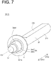
- FIG. 7 is a schematic perspective view of the stir pin 3B according to the second embodiment, schematically illustrating this stir pin 3B.
- FIG. 4 is a schematic cross-sectional view of the friction stir welding tool 100B according to the second embodiment, schematically illustrating this friction stir welding tool 100B.
- FIG. 5 is a schematic enlarged cross-sectional view of the friction stir welding tool 100B according to the second embodiment, with part of the friction stir welding tool 100B enlarged.
- FIG. 6 is a schematic cross-sectional view of the stir pin 3B according
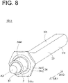
- FIG. 8 is a schematic perspective view of a stir pin 3B according to a first modification of the second embodiment, schematically illustrating this stir pin 3B.
- FIG. 9 is a schematic perspective view of a stir pin 3B according to a second modification of the second embodiment, schematically illustrating this stir pin 3B.
- FIG. 10 is a schematic perspective view of a stir pin 3B according to a third modification of the second embodiment, schematically illustrating this stir pin 3B.
- the stir pin 3B (or the friction stir welding tool 100B) according to the second embodiment is different from the stir pin 3A (or the friction stir welding tool 100A) according to the first embodiment in that the ring-shaped receiving surface 341s has a form of flange F. Otherwise, the stir pin 3B (or the friction stir welding tool 100B) according to the second embodiment is similar to the stir pin 3A (or the friction stir welding tool 100A) according to the first embodiment.
- the stir pin 3B includes: a base end portion 30, which is holdable by the pin holder 8; an intermediate portion 34; and a stirring portion 37 (in other words, leading end portion).
- the structure and the shape of the base end portion 30 described in the first embodiment may be employed as the structure and the shape of the base end portion 30 of the stir pin 3B.
- the structure and the shape of the stirring portion 37 described in the first embodiment may be employed as the structure and the shape of the stirring portion 37 of the stir pin 3B.
- the intermediate portion 34 includes a first portion 340 and a second portion 344.
- the structure and the shape of the second portion 344 described in the first embodiment may be employed as the structure and the shape of the second portion 344 according to the second embodiment.
- the first portion 340 is a portion provided further in the second direction DR2 than the end P3 of the ring-shaped receiving surface 341s on the first direction DR1 side.
- the second portion 344 is a portion provided further in the first direction DR1 than the end P3 of the ring-shaped receiving surface 341s on the first direction DR1 side.
- the first portion 340 includes a protrusion 341, which protrudes in a direction away from the first axis AX beyond the outer surface 344t of the second portion 344.
- the protrusion 341 includes the flange F, which protrudes in a direction away from the first axis AX.
- the flange F may also be referred to as a brim or a disc.
- the surface of the flange F pointed in the first direction DR1 defines the ring-shaped receiving surface 341s.
- the shape of the ring-shaped receiving surface 341s described in the first embodiment may be employed as the shape of the ring-shaped receiving surface 341s according to the second embodiment.
- the position of the ring-shaped receiving surface 341s relative to the shoulder member 7 described in the first embodiment may be employed as the position of the ring-shaped receiving surface 341s relative to the shoulder member 7 (more specifically, the second through hole 74h) according to the second embodiment.
- the stir pin 3B (or the friction stir welding tool 100B) according to the second embodiment has a ring-shaped receiving surface 341s. With this configuration, the stir pin 3B (or the friction stir welding tool 100B) according to the second embodiment provides effects similar to the effects provided by the stir pin 3A (or the friction stir welding tool 100A) according to the first embodiment.
- the surface of the flange F pointed in the second direction DR2 (in other words, a rear surface 342 of the flange F) is pointed to the leading end portion 8e (or a face 80e) of the pin holder 8 on the first direction DR1 side.
- This configuration enables the flange F to cover (in other words, protect) at least a part of the leading end portion 8e of the pin holder 8 on the first direction DR1 side.
- the above configuration also enables the flange F to prevent material waste from attaching to the leading end portion 8e of the pin holder 8 on the first direction DR1 side.
- the boundary BR between the outer surface of the base end portion 30 of the stir pin 3B and the inner surface of the pin holder 8 is covered by the flange F.
- the material waste is prevented from entering the gap between the outer surface of the base end portion 30 of the stir pin 3B and the inner surface of the pin holder 8.
- the pin holder 8 and the stir pin 3B are prevented from being fixed to each other via the material waste.
- the pin holder 8 is prevented from being deformed (more specifically, the first hole 81h, which receives the stir pin 3B, is prevented from being deformed).
- the outer diameter of the ring-shaped receiving surface 341s is larger than the outer diameter of the base end portion 30 of the stir pin 3B.
- a first imaginary circle is defined by an outermost edge P1 of the ring-shaped receiving surface 341s (that is, a point that is among the points on the ring-shaped receiving surface 341s and that is farthest from the first axis AX) rotating about the first axis AX, and the radius of the first imaginary circle is defined as a first radius D1 ; and a second imaginary circle is defined by an outermost edge P2 of the base end portion 30 (that is, a point that is among the points on the outer circumferential surface of the base end portion 30 and that is farthest from the first axis AX) rotating about the first axis AX, and the radius of the second imaginary circle is defined as a second radius D2.
- the first radius D1 is larger the second radius D2 .
- the distance between the outermost edge P1 of the ring-shaped receiving surface 341s and the first axis AX is equal to the maximum distance between an arbitrary point on the outer circumferential surface of the stir pin 3B and the first axis AX.
- the boundary BR between the outer surface of the base end portion 30 of the stir pin 3B and the inner surface of the pin holder 8 is hidden behind the ring-shaped receiving surface 341s. This reliably prevents the material waste from entering the gap between the outer surface of the base end portion 30 of the stir pin 3B and the inner surface of the pin holder 8.
- the outer circumstantial shape of the flange F is a circular shape.
- the outer circumstantial shape of the flange F may be a non-circular shape (for example, a polygonal shape such as a hexagonal shape).
- the ring-shaped receiving surface 341s is a smooth surface.
- a protrusion, a depression, or a groove may be formed on the ring-shaped receiving surface 341s.
- a plurality of protrusions 341d are formed on the ring-shaped receiving surface 341s.
- the material waste entering the gap between the ring-shaped receiving surface 341s and the shoulder member 7 is raked out by the plurality of protrusions 341d.
- the plurality of protrusions 341d are arranged at equal angular intervals around the first axis AX. It is to be noted that the arrangement of the plurality of protrusions 341d will not be limited to the arrangement illustrated in FIG. 9 ; any other arrangement is possible.
- Each of the protrusions 341d which are formed on the ring-shaped receiving surface 341s, may have such a shape that a width W of the protrusion 341d in a radial direction of the protrusion 341d (in other words, a direction perpendicular to the first axis AX) gradually increases along a circumferential direction of the protrusion 341d (more specifically, a direction opposite to the rotation direction R1 of the stir pin 3B).
- each of the protrusions 341d which are formed on the ring-shaped receiving surface 341s, may have such a shape that the height of the protrusion 341d (in other words, the height over which the protrusion 341d protrudes in the first direction DR1 ) gradually increases along the circumferential direction of the protrusion 341d (more specifically, the direction opposite to the rotation direction R1 of the stir pin 3B).
- a groove (more specifically, a spiral groove 341m) is formed on the ring-shaped receiving surface 341s.
- the spiral groove 341m preferably has such a shape that the distance from the first axis AX gradually increases along the circumferential direction (more specifically, the direction opposite to the rotation direction R1 of the stir pin 3B). In this case, the spiral groove 341m rotates about the first axis AX together with the stir pin 3B, causing the material waste contacting the spiral groove 341m to move in a radially outward direction.
- FIG. 11 is a schematic enlarged cross-sectional view of the friction stir welding tool 100C according to the third embodiment, with part of the friction stir welding tool 100C enlarged.
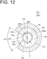
- FIG. 12 is a cross-sectional view of the friction stir welding tool 100C cut along a plane indicated by the arrow A-A illustrated in FIG. 11 .
- the stir pin 3 and the pin holder 8 are indicated by broken lines.
- the shoulder member 7C (or the friction stir welding tool 100C) according to the third embodiment is characterized in the shape and the structure of the leading end portion 72 of the shoulder member 7. Otherwise, the shoulder member 7C (or the friction stir welding tool 100C) according to the third embodiment is similar to the shoulder member 7 (or the friction stir welding tool 100A) according to the first embodiment or to the shoulder member 7 (or the friction stir welding tool 100B) according to the second embodiment.
- the shoulder member 7 (more specifically, the leading end portion 72 of the shoulder member 7) has a first through hole 72h, through which the stir pin 3 is passed.
- the stir pin 3 according to the third embodiment may be the stir pin 3A according to the first embodiment, the stir pin 3B according to the second embodiment, or any other stir pin.
- the shoulder member 7 (more specifically, the leading end portion 72 of the shoulder member 7) includes a material waste receiving portion 720.
- the material waste receiving portion 720 is closer to the base end portion than the first through hole 72h is to the base end portion (in other words, the material waste receiving portion 720 is provided further in the second direction DR2 than the first through hole 72h).
- a pocket PC which is for receiving the material waste, is defined by: a wall surface 720s (more specifically, the inner circumferential surface of the material waste receiving portion 720), which defines the material waste receiving portion 720; and the outer circumferential surface of the stir pin 3.
- the shoulder member 7 (more specifically, the leading end portion 72 of the shoulder member 7) has a second through hole 74h, through which the material waste is discharged. Also in the example illustrated in FIG. 11 , the pocket PC is connected to the second through hole 74h. In this case, the material waste temporarily stored in the pocket PC is discharged to the outside of the shoulder member 7 through the second through hole 74h.
- the number of second through holes 74h (in other words, discharge holes) that the shoulder member 7 has is one.
- the number of second through holes 74h that the shoulder member 7 has may be two or more.
- the end of the pocket PC on the second direction DR2 side is covered by the ring-shaped receiving surface 341s.
- the material waste entering the pocket PC is smoothly guided to the second through hole 74h by the ring-shaped receiving surface 341s.
- the end of the pocket PC on the first direction DR1 side is substantially covered by an inward protrusion 72r, which is provided at the leading end portion 72 of the shoulder member 7. This ensures that the inward protrusion 72r reduces the intrusion of the material waste into the pocket PC.
- the material waste receiving portion 720 is provided such that a cross-section CS2 crosses the second through hole 74h.
- the cross-section CS2 passes through the material waste receiving portion 720 and is perpendicular to the first axis AX. In this case, the material waste received in the material waste receiving portion 720 is smoothly moved to the second through hole 74h using centrifugal force.
- the inner diameter, D3 , of the material waste receiving portion 720 is larger than the inner diameter, D4 , of the first through hole 72h. In this case, the material waste entering the shoulder member 7 through the first through hole 72h is smoothly received in the material waste receiving portion 720.
- the first inner surface 72b of the shoulder member 7 (in other words, the surface pointed to the ring-shaped receiving surface 341s or the surface pointed in the second direction DR2 ) has a first area 721 and a second area 722, which is depressed in the first direction DR1 beyond the first area 721.
- the first area 721 and the second area 722 may be connected to each other via an inclined surface 723.
- the first area 721 and the second area 722 may be connected to each other via a step 724.
- the inclined surface 723 is provided at one side portion of the second area 722, and the step 724 is provided at an opposite side portion of the second area 722.
- the first inner surface 72b of the shoulder member 7 has the first area 721 and the second area 722, which is depressed in the first direction DR1 beyond the first area 721.
- the material waste entering the internal region (more specifically, the pocket PC) of the material waste receiving portion 720 is smoothly guided to the region of a back portion of the second area 722 (when the stirring portion 37 is pointed downward, the region of the back portion of the second area 722 corresponds to the region immediately over the second area 722).
- the material waste entering the minimal gap between the first area 721 and the ring-shaped receiving surface 341s is smoothly guided to the region of the back portion of the second area 722 through the inclined surface 723.
- the step 724 is provided between the first area 721 and the second area 722, it is difficult for the material waste guided to the region of the back portion of the second area 722 to enter the minimal gap between the first area 721 and the ring-shaped receiving surface 341s.
- the second area 722 is provided in an angle range AR1, which extends from the first axis AX toward a discharge opening EP of the second through hole 74h.
- the material waste guided to the region of the back portion of the second area 722 is moved smoothly toward the discharge opening EP of the second through hole 74h.
- the inclined surface 723 may be provided in the angle range AR1, which extends from the first axis AX toward a discharge opening EP of the second through hole 74h.
- FIG. 13 is a schematic partial cross-sectional view of the machine tool 200 according to the fourth embodiment, schematically illustrating this machine tool 200.
- the machine tool 200 includes: a friction stir welding tool 100D; a workpiece support member 201; a tool support member 203, which supports the friction stir welding tool 100D; a first driver 205, which moves the tool support member 203 relative to the workpiece support member 201; a second driver 207, which drives the stir pin 3 into rotation; and a controller 209.
- An example of the friction stir welding tool 100D according to the fourth embodiment is the friction stir welding tool (100A, 100B, 100C) according to any one of the above-described embodiments.
- the friction stir welding tool has already been described in the first to third embodiments, and a redundant description of the friction stir welding tool is omitted.
- the workpiece support member 201 supports workpieces W, which are to-be-worked objects (more specifically, to-be-joined objects).
- An example of the workpiece support member 201 is a support table to which the workpieces W are fixed.
- the workpiece support member 201 (support table) supports a first workpiece W1 and a second workpiece W2.
- the first workpiece W1 and the second workpiece W2 are joined together using the friction stir welding tool 100D.
- the first workpiece W1 and the second workpiece W2 may be joined together continuously (in other words, linearly) using the friction stir welding tool 100D.
- the first workpiece W1 and the second workpiece W2 may be spot-welded (in other words, point-welded) together using the friction stir welding tool 100D.
- the machine tool 200 includes a base 202 and a driver 205a (for example, a support table driver), which moves the workpiece support member 201 relative to the base 202.
- the driver 205a is one example of the first driver 205, which moves the tool support member 203 relative to the workpiece support member 201.
- the tool support member 203 supports the friction stir welding tool 100D.
- the tool support member 203 includes: a frame 203a, to which the shoulder member 7 is fixed; and a shaft 203b, which transmits rotational force to the pin holder 8.
- the tool support member 203 may also be referred to as a headstock.
- the shaft 203b may also be referred to as a rotation spindle.
- the machine tool 200 includes a second base 204 and a driver 205b, which moves the tool support member 203 relative to the second base 204.
- the driver 205b is another example of the first driver 205, which moves the tool support member 203 relative to the workpiece support member 201.
- the first driver 205 is a device that moves the tool support member 203 relative to the workpiece support member 201.
- the first driver 205 includes: the driver 205a, which moves the workpiece support member 201 relative to the base 202; and the driver 205b, which moves the tool support member 203 relative to the second base 204.
- the first driver 205 may include only one of the driver 205a and the driver 205b.
- the driver 205a is a device that moves the workpiece support member 201 in a direction along a horizontal plane (in other words, in a direction along the X-Y plane).
- the driver 205b is a device that moves the tool support member 203 three-dimensionally.
- the driver 205b is capable of moving the tool support member 203 in a direction along the X axis, capable of moving the tool support member 203 in a direction along the Y axis, and capable of moving the tool support member 203 in a direction along the Z axis.
- the Z axis is a direction along a vertical direction and is a direction parallel to the first direction DR1.
- the second driver 207 drives the stir pin 3 into rotation. More specifically, the second driver 207 is connected to the shaft 203b in such a manner that motive power can be transmitted to the shaft 203b. With this configuration, the second driver 207 drives the stir pin 3 into rotation via the shaft 203b and the pin holder 8.
- the controller 209 controls the first driver 205 and the second driver 207.
- the controller 209 includes: first driver controlling means 209a, which controls the first driver 205; and second driver controlling means 209b, which controls the second driver 207.
- the first driver 205 Upon receipt of a control signal from the controller 209 (more specifically, the first driver controlling means 209a), the first driver 205 moves the workpiece support member 201 and/or the tool support member 203. In other words, upon receipt of a control signal from the controller 209, the first driver 205 moves the tool support member 203 relative to the workpiece support member 201.
- the second driver 207 Upon receipt of a control signal from the controller 209 (more specifically, the second driver controlling means 209b), the second driver 207 rotates the stir pin 3 about the first axis AX. More specifically, upon receipt of a control signal from the controller 209, the second driver 207 rotates the shaft 203b. The rotation of the shaft 203b is transmitted to the stir pin 3 via the pin holder 8. Thus, the stir pin 3 rotates about the first axis AX.
- the controller 209 includes a storage device 2091 (in other words, a memory), which stores programs and data. By executing a program stored in the storage device 2091, the controller 209 serves as the first driver controlling means 209a and/or the second driver controlling means 209b.
- a storage device 2091 in other words, a memory
- the controller 209 serves as the first driver controlling means 209a and/or the second driver controlling means 209b.
- the machine tool 200 includes an input device 208, through which parameters such as a control parameter are input into the controller 209.
- the machine tool 200 includes the friction stir welding tool 100 according to any one of the above-described embodiments.
- the friction stir welding tool 100 that the machine tool 200 according to the fourth embodiment includes provides effects similar to the effects provided by the friction stir welding tools 100 according to the first to third embodiments.
- the machine tool 200 according to the fourth embodiment also includes the first driver 205, the second driver 207, and the controller 209. With this configuration, the machine tool 200 is capable of joining the first workpiece W1 and the second workpiece W2 together in any desired form by moving the tool support member 203 relative to the workpiece support member 201 and by rotating the stir pin 3.
- the shoulder member 7 is mounted on the frame 203a, which is not rotationally drivable.
- the force that the shoulder member 7 (more specifically, the shoulder surface 72s) receives from the workpieces W is supported by the frame 203a.
- the machine tool 200 according to the fourth embodiment is capable of rotating the shaft 203b at high speed.
- the machine tool 200 according to the fourth embodiment may not necessarily be a machine dedicated to friction stir welding.
- the machine tool 200 according to the fourth embodiment may be a multi-tasking machine capable of performing both friction stir welding and machining.
- the friction stir welding tool 100 may be attached to the tool support member 203; and in order to perform machining, a machining tool may be attached to the tool support member 203.
- the shoulder member 7 is described as including the second through hole 74h (in other words, a discharge hole).
- the shoulder member 7 may not necessarily be provided with the second through hole 74h.
- Second driver controlling means 340 ... First portion, 341 ... Protrusion, 341d ... Protrusion, 341m ... Spiral groove, 341s ... Receiving surface, 342 ... Rear surface, 344 ... Second portion, 344t ... Outer surface, 720 ... Material waste receiving portion, 720s ... Wall surface, 721 ... First area, 722 ... Second area, 723 ... Inclined surface, 724 ... Step, 2091 ... Storage device, 3410s ... Outer portion, 3411s ... Interior portion, AX ... First axis, BR ... Boundary, EP ... Discharge opening, F ... Flange, G ... Adjustment mechanism, GS ... Position adjustable surface, OP1 ... Opening, OP2 ... Opening, SP ... Internal space, TS ... Inclined surface, W ... Workpiece, W1 ... First workpiece, W2 ... Second workpiece
Landscapes
- Engineering & Computer Science (AREA)
- Mechanical Engineering (AREA)
- Pressure Welding/Diffusion-Bonding (AREA)
Abstract
Description
- The present invention relates to a stir pin, a friction stir welding tool, and a machine tool.
- Friction stir welding (Friction Stir Welding) is known. In friction stir welding, a tool pressed against two workpieces, which are joined objects, is rotated to weld the two workpieces together. More specifically, metal workpieces are softened by friction heat generated by the rotation of the tool. The softened metals are guided by the rotation of the tool to flow around the tool. Then, the metals flowing around the tool are solidified, so that the two workpieces are welded together.
- As a related technique, patent literature 1 discloses a friction stir tool. The friction stir tool recited in patent literature 1 includes a stir probe and a shoulder. The stir probe has a flow-prevention surface that changes the flow direction of a flowing object from the axial direction of the stir probe to its radial direction. Flowing metal is prevented by the flow-prevention surface from flowing farther and accumulates in an annular flowing-object container. In the friction stir tool recited in patent literature 1, the stir probe is directly connected to a rotational driving axis.
- Patent literature 2 discloses a friction stir welding tool. The friction stir welding tool recited in patent literature 2 includes a stir pin and a housing having a first surface. The housing has a discharge hole connecting a container hole formed on the first surface to the outside of the housing (through the discharge hole, excess metal is discharged).
-
- PTL1:
JP 2018-1178A - PTL2:
JP 6512727B1 - It is an object of the present invention to provide a stir pin, a friction stir welding tool, and a machine tool that prevent material waste from attaching to a pin holder.
- According to some embodiments of the present invention, a stir pin includes: a base end portion holdable by a pin holder; a stirring portion rotatable about a first axis relative to a shoulder member; and an intermediate portion provided between the base end portion and the stirring portion and rotatable about the first axis together with the stirring portion. The intermediate portion includes a first portion and a second portion that is provided further in a first direction than the first portion. The first direction is defined as a direction from the base end portion toward the stirring portion. The first portion includes a protrusion protruding beyond an outer surface of the second portion in a direction away from the first axis. the protrusion has a surface that is pointed in the first direction and defines a ring-shaped receiving surface that receives a material waste generated as a result of a friction stirring.
- According to some embodiments of the present invention, a friction stir welding tool includes: a shoulder member having a shoulder surface for pressing a workpiece; and a stir pin rotatable about a first axis relative to the shoulder member. The stir pin includes: a base end portion holdable by a pin holder; a stirring portion; and an intermediate portion provided between the base end portion and the stirring portion. The intermediate portion includes a first portion and a second portion that is provided further in a first direction than the first portion. The first direction is defined as a direction from the base end portion toward the stirring portion. The first portion includes a protrusion protruding beyond an outer surface of the second portion in a direction away from the first axis. The protrusion has a surface that is pointed in the first direction and that defines a ring-shaped receiving surface that prevents a material waste generated as a result of a friction stirring from attaching to the pin holder.
- According to some embodiments of the present invention, a machine tool includes: a friction stir welding tool; a workpiece support member configured to support a workpiece that is a to-be-machined object; a tool support member supporting the friction stir welding tool; a first driver configured to move the tool support member relative to the workpiece support member; a second driver configured to drive a stir pin into rotation; and a controller configured to control the first driver and the second driver. The friction stir welding tool includes: a shoulder member having a shoulder surface for pressing the workpiece; the stir pin, the stir pin being rotatable about a first axis relative to the shoulder member; and a pin holder. The stir pin includes: a base end portion held by the pin holder; a stirring portion; and an intermediate portion provided between the base end portion and the stirring portion. The intermediate portion includes a first portion and a second portion that is provided further in a first direction than the first portion. The first direction is defined as a direction from the base end portion toward the stirring portion. The first portion includes a protrusion protruding beyond an outer surface of the second portion in a direction away from the first axis. The protrusion has a surface that is pointed in the first direction and that defines a ring-shaped receiving surface that prevents a material waste generated as a result of a friction stirring from attaching to the pin holder.
- The embodiments of the present invention provide a stir pin, a friction stir welding tool, and a machine tool that prevent material waste from attaching to a pin holder.
-
- [
FIG. 1] FIG. 1 is a schematic cross-sectional view of a friction stir welding tool according to a first embodiment, schematically illustrating this friction stir welding tool. - [
FIG. 2] FIG. 2 is a schematic enlarged cross-sectional view of the friction stir welding tool according to the first embodiment, with part of the friction stir welding tool enlarged. - [
FIG. 3] FIG. 3 is a schematic cross-sectional view of a stir pin according to the first embodiment, schematically illustrating this stir pin. - [
FIG. 4] FIG. 4 is a schematic cross-sectional view of a friction stir welding tool according to a second embodiment, schematically illustrating this friction stir welding tool. - [
FIG. 5] FIG. 5 is a schematic enlarged cross-sectional view of the friction stir welding tool according to the second embodiment, with part of the friction stir welding tool enlarged. - [
FIG. 6] FIG. 6 is a schematic cross-sectional view of a stir pin according to the second embodiment, schematically illustrating this stir pin. - [
FIG. 7] FIG. 7 is a schematic perspective view of the stir pin according to the second embodiment, schematically illustrating this stir pin. - [
FIG. 8] FIG. 8 is a schematic perspective view of a stir pin according to a first modification of the second embodiment, schematically illustrating this stir pin. - [
FIG. 9] FIG. 9 is a schematic perspective view of a stir pin according to a second modification of the second embodiment, schematically illustrating this stir pin. - [
FIG. 10] FIG. 10 is a schematic perspective view of a stir pin according to a third modification of the second embodiment, schematically illustrating this stir pin. - [
FIG. 11] FIG. 11 is a schematic enlarged cross-sectional view of a friction stir welding tool according to a third embodiment, with part of the friction stir welding tool enlarged. - [
FIG. 12] FIG. 12 is a cross-sectional view of the friction stir welding tool cut along a plane indicated by the arrow A-A illustrated inFIG. 11 . - [
FIG. 13] FIG. 13 is a schematic partial cross-sectional view of a machine tool according to a fourth embodiment, schematically illustrating this machine tool. - [
FIG. 14] FIG. 14 is a schematic cross-sectional view of a friction stir welding tool according to a modification of an embodiment, schematically illustrating this friction stir welding tool. Description of Embodiments - By referring to the accompanying drawings, description will be made with regard to a
stir pin 3, a frictionstir welding tool 100, and amachine tool 200 according to some embodiments of the present invention. It is noted that in the following description of the embodiments, identical reference numerals are used to denote identical portions, members, or components having identical functions, and redundant description of identical portions, members, or components will be eliminated or minimized. - As used herein, the term "first direction DR1" is defined as a direction from a
base end portion 30 of the stir pin 3 (or a base end portion of the shoulder member 7) toward astirring portion 37 of the stir pin 3 (or ashoulder surface 72s of the shoulder member 7). Also as used herein, the term "second direction DR2" is defined as a direction opposite to the first direction DR1. For example, when a leading end portion of thestir pin 3 is pointed downward, the first direction DR1 corresponds to downward direction, and the second direction DR2 corresponds to upward direction. - As used herein, the term "machine tool" is intended to mean any machine to which a friction stir welding tool is attachable. The machine tool may be a combined multi-functional machine tool, which is capable of performing a plurality of different kinds of machining (an example is a machining center). An example of the machine tool is a machine capable of cutting, machining, grinding, or joining metal.
- As used herein, the term "material waste" is intended to mean a piece of material detached from a workpiece as a result of a friction stirring. When the friction
stir welding tool 100 joins metal workpieces together, the term "workpiece", as used herein, can be rephrased as "metal workpiece", and the term "material waste", as used herein, can be rephrased as "metal waste". This, however, does not exclude any configuration in which the frictionstir welding tool 100 is used to join non-metal workpieces (for example, resin workpieces) together. - By referring to
FIGs. 1 to 3 , a frictionstir welding tool 100A and astir pin 3A according to the first embodiment will be described.FIG. 1 is a schematic cross-sectional view of the frictionstir welding tool 100A according to the first embodiment, schematically illustrating the frictionstir welding tool 100A.FIG. 2 is a schematic enlarged cross-sectional view of the frictionstir welding tool 100A according to the first embodiment, with part of the frictionstir welding tool 100A enlarged.FIG. 3 is a schematic cross-sectional view of thestir pin 3A according to the first embodiment, schematically illustrating thisstir pin 3A. - The friction
stir welding tool 100A according to the first embodiment includes theshoulder member 7 and thestir pin 3A. - In the example illustrated in
FIG. 1 , theshoulder member 7 has theshoulder surface 72s. Theshoulder surface 72s is for pressing workpieces, which are to-be-joined objects. Theshoulder surface 72s is the end face of theshoulder member 7 on the first direction DR1 side. Theshoulder surface 72s flattens material (of which the workpiece is made) softened by the rotation of thestir pin 3A. In the example illustrated inFIG. 1 , theshoulder surface 72s is a surface perpendicular to the first direction DR1 (in other words, perpendicular to a first axis AX, described later). - In the example illustrated in
FIG. 1 , theshoulder member 7 includes: afirst member 70, which has theshoulder surface 72s; and asecond member 76. Thefirst member 70 is mounted on thesecond member 76. In the example illustrated inFIG. 1 , thefirst member 70 and thesecond member 76 are threaded to each other. The configuration in which theshoulder member 7 includes thefirst member 70 and thesecond member 76 makes the frequency by which thesecond member 76 is replaced lower than the frequency by which thefirst member 70 is replaced. As a result, the running cost involved in the use of the frictionstir welding tool 100A is reduced. - In the example illustrated in
FIG. 1 , theshoulder member 7 is an assembly of two piece-parts (70, 76). Alternatively, theshoulder member 7 may be made up of a single piece-part or may be an assembly of three or more piece-parts. - In the example illustrated in
FIG. 1 , theshoulder member 7 has an internal space SP, which extends along the first direction DR1. In the internal space SP, at least a part of thestir pin 3A is provided. That is, theshoulder member 7 also functions as a housing member for at least a part of thestir pin 3A. In the example illustrated inFIG. 1 , the entirety of thestir pin 3A is provided in the internal space SP of theshoulder member 7. - The stirring
portion 37 of thestir pin 3A is inserted into workpieces with the stirringportion 37 in rotating state. Thestir pin 3A may also be referred to as a probe. Then, frictional heat generated by the friction between thestir pin 3A and the workpieces makes the material of the workpieces (more specifically, metal material) softened. The softened material is stirred by therotating stir pin 3A. Then, the stirred material is solidified, and thus the workpieces are joined together. - In the example illustrated in
FIG. 1 , thestir pin 3A is rotatable about the first axis AX relative to theshoulder member 7. - In the example illustrated in
FIG. 1 , thestir pin 3A rotates relative to the workpieces, whereas theshoulder surface 72s does not rotate relative to the workpieces. In the configuration in which theshoulder surface 72s does not rotate relative to the workpieces, the area over which frictional heat is generated is smaller than in the configuration in which theshoulder surface 72s rotates relative to the workpieces. This reduces the occurrence of workpiece deformation and burrs, resulting in a more satisfactory joint surface. Also in the configuration in which theshoulder surface 72s does not rotate relative to the workpieces, the area of contact between the workpieces and the rotatable member (more specifically, thestir pin 3A) is smaller. This requires a smaller level of force in pressing the rotatable member (more specifically, thestir pin 3A) against the workpieces in a friction stir welding. - The
stir pin 3A includes thebase end portion 30, anintermediate portion 34, and the stirring portion 37 (in other words, a leading end portion). - The
base end portion 30 is a portion holdable by apin holder 8. Upon rotation of thepin holder 8 about the first axis AX, thebase end portion 30 held by thepin holder 8 rotates about the first axis AX relative to theshoulder member 7. - When the
stir pin 3A is mounted on thepin holder 8, thebase end portion 30 is provided further in the second direction DR2 than aleading end portion 8e of thepin holder 8. - The stirring
portion 37 is a portion to be inserted into the workpieces and to stir the material of the workpieces. The stirringportion 37 protrudes beyond theshoulder surface 72s in the first direction DR1. The stirringportion 37 is rotatable about the first axis AX relative to theshoulder member 7. By rotating the stirringportion 37 about the first axis AX, the workpieces contacting the stirringportion 37 are stirred due to the friction between the workpieces and the stirringportion 37. - The
intermediate portion 34 is a portion provided between thebase end portion 30 and the stirringportion 37. In the example illustrated inFIG. 2 , the portion of thestir pin 3A that is provided further in the first direction DR1 than theleading end portion 8e of thepin holder 8 and that is provided further in the second direction DR2 than theshoulder surface 72s is theintermediate portion 34. - The
intermediate portion 34 is rotatable about the first axis AX together with the stirringportion 37. Theintermediate portion 34 is also rotatable about the first axis AX together with thebase end portion 30. For example, the stirringportion 37, theintermediate portion 34, and thebase end portion 30 make up a single, integrally formed piece-part. - In the example illustrated in
FIG. 2 , theintermediate portion 34 includes afirst portion 340 and asecond portion 344, which is provided further in the first direction DR1 than thefirst portion 340. - The
first portion 340 includes aprotrusion 341, which protrudes beyond anouter surface 344t of thesecond portion 344 in a direction away from the first axis AX. Also, the surface of theprotrusion 341 pointed in the first direction DR1 defines a ring-shapedreceiving surface 341s, which receives a material waste generated as a result of a friction stirring. - Functions of the ring-shaped
receiving surface 341s will be described. - The following description assumes a case in which the stirring
portion 37 illustrated in the example illustrated inFIG. 2 rotates about the first axis AX with the workpieces and the stirringportion 37 in mutually contacting state. In this case, part of the material (in other words, material waste) detached from the workpieces as a result of a friction stirring enters theshoulder member 7 through a first throughhole 72h, which is provided at aleading end portion 72 of theshoulder member 7. The material waste entering theshoulder member 7 is received by the ring-shapedreceiving surface 341s. The material waste received by the ring-shapedreceiving surface 341s is moved in a direction away from the first axis AX by centrifugal force generated by the ring-shapedreceiving surface 341s rotating about the first axis AX. - If the material waste attached to the
pin holder 8 is cooled and solidified, it is possible that thepin holder 8 and thestir pin 3A are fixed to each other via the material waste. In contrast, in thestir pin 3A and the frictionstir welding tool 100A according to the first embodiment, the material waste is moved in a direction away from the first axis AX Thus, the material waste is prevented from attaching to the pin holder 8 (in particular, to the boundary, BR, between thepin holder 8 and thestir pin 3A). - In the
stir pin 3A and the frictionstir welding tool 100A according to the first embodiment, thepin holder 8 and thestir pin 3A are prevented from being fixed to each other via the material waste. This makes thestir pin 3A easily detachable from the pin holder 8 (in other words, thestir pin 3A is made easily replaceable). Also, since no material waste enters the gap between thepin holder 8 and thestir pin 3A, thepin holder 8 is prevented from being deformed (more specifically, afirst hole 81h, which receives thestir pin 3A, is prevented from being deformed). - Next, by referring to
FIGs. 1 to 3 , an optional configuration employable in the first embodiment will be described. - In the example illustrated in
FIG. 3 , the outer diameter of the ring-shapedreceiving surface 341s is equal to the outer diameter of thebase end portion 30 of thestir pin 3A. In other words, a first imaginary circle is defined by an outermost edge P1 of the ring-shapedreceiving surface 341s (that is, a point that is among the points on the ring-shapedreceiving surface 341s and that is farthest from the first axis AX) rotating about the first axis AX, and the radius of the first imaginary circle is defined as a first radius D1; and a second imaginary circle is defined by an outermost edge P2 of the base end portion 30 (that is, a point that is among the points on the outer circumferential surface of thebase end portion 30 and that is farthest from the first axis AX) rotating about the first axis AX, and the radius of the second imaginary circle is defined as a second radius D2. In this case, the first radius D1 is equal to the second radius D2. Also in the example illustrated inFIG. 3 , the distance between the outermost edge P1 of the ring-shapedreceiving surface 341s and the first axis AX is equal to the maximum distance between an arbitrary point on the outer circumferential surface of thestir pin 3A and the first axis AX. - As exemplified in
FIG. 2 , in the configuration in which thebase end portion 30 of thestir pin 3A is held by thepin holder 8, the position of the outer surface of thebase end portion 30 of thestir pin 3A is approximately equal to the position of the inner surface of thepin holder 8. With this configuration, the material waste received by the ring-shapedreceiving surface 341s is moved by centrifugal force in a direction away from the first axis AX beyond the outermost edge P1 of the ring-shapedreceiving surface 341s. Thus, the material waste is prevented from entering the gap between the outer surface of thebase end portion 30 of thestir pin 3A and the inner surface of thepin holder 8. - It is to be noted that from the viewpoint of more reliably preventing the material waste from entering the gap between the outer surface of the
base end portion 30 of thestir pin 3A and the inner surface of thepin holder 8, the outer diameter of the ring-shapedreceiving surface 341s is preferably larger than the outer diameter of thebase end portion 30 of thestir pin 3A (seeFIG. 6 ). In other words, the first radius D1 is preferably larger than the second radius D2. - In the example illustrated in
FIG. 2 , the ring-shapedreceiving surface 341s includes a protruding curved surface (in other words, a curved surface protruding in the first direction DR1). In this case, the gap between the ring-shapedreceiving surface 341s and the shoulder member 7 (more specifically, a firstinner surface 72b, described later) becomes smaller. This prevents the material waste from entering the gap between the ring-shapedreceiving surface 341s and the firstinner surface 72b. - In the example illustrated in
FIG. 2 , anouter portion 3410s of the ring-shapedreceiving surface 341s has an inclined surface TS, which is inclined in a direction toward the first axis AX as the inclined surface TS is closer to the stirringportion 37. In this case, aninner portion 3411s of the ring-shapedreceiving surface 341s protrudes toward the first direction DR1 side beyond theouter portion 3410s of the ring-shapedreceiving surface 341s. This diminishes the gap between theinner portion 3411s of the ring-shapedreceiving surface 341s and the shoulder member 7 (more specifically, the firstinner surface 72b). Thus, the material waste is prevented from entering the gap between the ring-shapedreceiving surface 341s and the firstinner surface 72b. The shape of the cross-section of the inclined surface TS (a cross-section cut along a plane including the first axis AX) may be a curvilinear shape, as exemplified inFIG. 2 , or may be a linear shape. - In the example illustrated in
FIG. 3 , thefirst portion 340 of theintermediate portion 34 is a portion provided further in the second direction DR2 than an end P3 of the ring-shapedreceiving surface 341s on the first direction DR1 side. As exemplified inFIG. 2 , when thestir pin 3A is mounted on thepin holder 8, thefirst portion 340 of theintermediate portion 34 is provided further in the first direction DR1 than theleading end portion 8e of thepin holder 8. Thus, the ring-shapedreceiving surface 341s, which is provided at thefirst portion 340, prevents the material waste from attaching to thepin holder 8. Also, thefirst portion 340 is provided further in the second direction DR2 than the firstinner surface 72b of theshoulder member 7. This enables the ring-shapedreceiving surface 341s, which is provided at thefirst portion 340, to receive the material waste entering theshoulder member 7. - In the example illustrated in
FIG. 3 , thesecond portion 344 of theintermediate portion 34 is a portion provided further in the first direction DR1 than the end P3 of the ring-shapedreceiving surface 341s on the first direction DR1 side. Also, thesecond portion 344 of theintermediate portion 34 is a portion provided further in the second direction DR2 than the stirringportion 37. As exemplified inFIG. 2 , in the configuration in which theshoulder member 7 is provided outside thestir pin 3A, thesecond portion 344 of theintermediate portion 34 is provided between theshoulder surface 72s and the ring-shapedreceiving surface 341s. In the example illustrated inFIG. 2 , part of thesecond portion 344 is provided in the first throughhole 72h of theshoulder member 7. - When material waste has entered the
shoulder member 7 through the first throughhole 72h of theshoulder member 7, the material waste is guided by theouter surface 344t of thesecond portion 344 in a direction toward the ring-shapedreceiving surface 341s. In a cross-section perpendicular to the first axis AX, an example shape of theouter surface 344t of thesecond portion 344 is a circular shape. - In the example illustrated in
FIG. 3 , the stirringportion 37 has a tapered shape. The stirringportion 37 may be threaded on at least a part of the side surface. The shape of the cross-section of the stirringportion 37 cut along a plane perpendicular to the first axis AX may be a circular shape, an approximately polygonal shape (for example, a round-cornered triangle), or any other shape. - In the example illustrated in
FIG. 3 , thebase end portion 30 of thestir pin 3A has an outercircumferential surface 30t and abase end surface 30s. The outercircumferential surface 30t may have a circularfirst surface 31t and a planarsecond surface 32t. - In the example illustrated in
FIG. 2 , thefirst surface 31t has a shape complementary to the inner circumferential surface of thepin holder 8, which defines thefirst hole 81h of thepin holder 8. In a cross-section perpendicular to the first axis AX, thefirst surface 31t has a circular shape. - The
base end portion 30 has a pressed surface pressable by a first fixingmember 83. In the example illustrated inFIG. 2 , the pressed surface is the above-describedsecond surface 32t. In a cross-section perpendicular to the first axis AX, thesecond surface 32t has a linear shape. - By pressing the pressed surface (more specifically, the
second surface 32t), the first fixingmember 83 fixes thebase end portion 30 of thestir pin 3A to thepin holder 8 unmovably relative to thepin holder 8. - The
base end portion 30 has a position adjustable surface GS, whose position in a direction along the first direction DR1 is adjustable by astopper member 85, described later. In the example illustrated inFIG. 1 , the position adjustable surface GS is thebase end surface 30s. An example of thebase end surface 30s is a flat surface. A mechanism for adjusting the position of the position adjustable surface GS using thestopper member 85 will be described later. - In the example illustrated in
FIG. 2 , theshoulder member 7 has theshoulder surface 72s and the firstinner surface 72b. Theshoulder surface 72s is a surface of theshoulder member 7 pointed in the first direction DR1, and the firstinner surface 72b is a surface of theshoulder member 7 facing the ring-shapedreceiving surface 341s. - In the example illustrated in
FIG. 2 , the position of thestir pin 3A is adjustable so that the gap between the firstinner surface 72b of theshoulder member 7 and the ring-shapedreceiving surface 341s is a minimal gap. In this case, it is difficult for the material waste to enter the gap between the firstinner surface 72b and the ring-shapedreceiving surface 341s. - As used herein, the term "minimal gap" is intended to mean a gap so small that material waste is substantially prevented from entering the gap. The size of the minimal gap (in other words, the gap between the first
inner surface 72b and the ring-shapedreceiving surface 341s) is, for example, 2 mm or less, 1 mm or less, or 0.5 mm or less. - In the example illustrated in
FIG. 2 , theshoulder member 7 has a second throughhole 74h, in addition to the first throughhole 72h. Through the second throughhole 74h, the material waste entering theshoulder member 7 is discharged to the outside of theshoulder member 7. - In the example illustrated in
FIG. 2 , the first throughhole 72h is provided on theshoulder surface 72s of theshoulder member 7. The first throughhole 72h extends along the first direction DR1. - In the example illustrated in
FIG. 2 , the second throughhole 74h is provided on the side surface of theshoulder member 7. The second throughhole 74h extends in a direction crossing the first direction DR1 (for example, a direction orthogonal to the first direction DR1). In the example illustrated inFIG. 2 , the number of second throughholes 74h (in other words, through holes through which to discharge the material waste) that theshoulder member 7 has is one. Alternatively, the number of second throughholes 74h that theshoulder member 7 has may be two, or three or more. - In the configuration in which the
shoulder member 7 includes the second throughhole 74h, the material waste is prevented from staying in theshoulder member 7. This, as a result, prevents the wear of thestir pin 3A and/or thepin holder 8 that may otherwise occur due to the friction between thestir pin 3A and/or thepin holder 8 and the material waste (more specifically, metal waste). Also in the configuration in which the material waste is discharged to the outside of theshoulder member 7, the material waste (more specifically, metal waste) is prevented from being stirred continuously in theshoulder member 7. This, as a result, prevents overheating of thestir pin 3A and/or thepin holder 8. - Thus, in the configuration in which the
shoulder member 7 includes the second throughhole 74h, thestir pin 3A and/or thepin holder 8 are kept in good condition. Thus, the lifetime (durability) of thestir pin 3A and/or thepin holder 8 is elongated. Also, as a result of thestir pin 3A and/or thepin holder 8 being kept in good condition, the joint surfaces of the workpieces are kept in good quality. - In the example illustrated in
FIG. 2 , from the viewpoint of efficiently discharging the material waste to the outside of theshoulder member 7,the position of thestir pin 3A is preferably adjustable so that a cross-section CS1 crosses the second throughhole 74h. The cross-section CS1 passes through the outermost edge P1 of the ring-shapedreceiving surface 341s and is perpendicular to the first axis AX. In this case, the material waste receives centrifugal force from the ring-shapedreceiving surface 341s, and using this centrifugal force, the material waste can be guided to the second throughhole 74h. - In the example illustrated in
FIG. 2 , an opening OP1 of the second throughhole 74h on the second direction DR2 side is substantially covered by the ring-shapedreceiving surface 341s; and an opening OP2 of the second throughhole 74h on the first axis AX side is substantially covered by the outer circumferential surface (344t) of thestir pin 3A. In this case, the material waste entering theshoulder member 7 through the first throughhole 72h is smoothly guided to the second throughhole 74h. - In the example illustrated in
FIG. 2 , the outermost edge P1 of the ring-shapedreceiving surface 341s is provided further in the first direction DR1 than an end P4 of the second throughhole 74h on the second direction DR2 side. In this case, the material waste entering theshoulder member 7 is effectively prevented from moving in the second direction DR2 beyond the second throughhole 74h. Thus, the material waste is prevented from staying in theshoulder member 7 for the elongated period of time that the material waste may otherwise take if the material waste came farther in theshoulder member 7 beyond the second throughhole 74h. - The friction
stir welding tool 100A (more specifically, the pin holder 8) preferably includes an adjustment mechanism G (seeFIG. 1 ), which adjusts the position of the ring-shapedreceiving surface 341s in the first direction DR1. This is from the viewpoint of adjusting the position of the ring-shapedreceiving surface 341s so that the gap between the firstinner surface 72b of theshoulder member 7 and the ring-shapedreceiving surface 341s is a minimal gap; and/or the viewpoint of adjusting the position of the ring-shapedreceiving surface 341s so that the outermost edge P1 of the ring-shapedreceiving surface 341s is positioned further in the first direction DR1 than the end P4 of the second throughhole 74h on the second direction DR2 side. Details of the adjustment mechanism G will be described later. - In the example illustrated in
FIG. 1 , the frictionstir welding tool 100A includes thepin holder 8, which is rotatable about the first axis AX together with thestir pin 3A. - The
pin holder 8 includes: aholder body 80; thefirst hole 81h, which is for receiving thebase end portion 30 of thestir pin 3A; and the first fixingmember 83, which is for fixing thebase end portion 30 of thestir pin 3A to theholder body 80. - The
first hole 81h is provided in theholder body 80 and extends along the first direction DR1. In the example illustrated inFIG. 1 , thefirst hole 81h is capable of receiving thebase end portion 30 of thestir pin 3A, and is capable of receiving a leading end portion of thestopper member 85, described later. - In the example illustrated in
FIG. 1 , theholder body 80 has asecond hole 82h. Thesecond hole 82h is formed on the side wall of theholder body 80. Thesecond hole 82h is connected to thefirst hole 81h. - In the
second hole 82h, the first fixingmember 83 is inserted. The first fixingmember 83 is for fixing thebase end portion 30 of thestir pin 3A. An example of the first fixingmember 83 is a set screw. In the example illustrated inFIG. 2 , the first fixingmember 83 has anexternal screw portion 83a, which is screwable with aninternal screw portion 82a, which is formed on thesecond hole 82h. - In the example illustrated in
FIG. 1 , thepin holder 8 includes the adjustment mechanism G, which adjusts the position of the ring-shapedreceiving surface 341s. The adjustment mechanism G includes: thestopper member 85, which is contactable with the position adjustable surface GS (more specifically, thebase end surface 30s) of thestir pin 3A; and aguide 86, which guides the movement of thestopper member 85. - The
guide 86 is implemented by, for example, athird hole 86h, which is formed on the side wall of the pin holder 8 (more specifically, the holder body 80). In the example illustrated inFIG. 1 , thethird hole 86h is connected to thefirst hole 81h. Thethird hole 86h is inclined relative to thefirst hole 81h. - In the example illustrated in
FIG. 1 , the position of thestopper member 85 is adjustable along the guide 86 (more specifically, thethird hole 86h). In this manner, the position of the stopper member 85 (more specifically, astopper surface 85s, which is contactable with the position adjustable surface GS of thestir pin 3A) in a direction along the first direction DR1 is adjustable. By adjusting the position of thestopper surface 85s in a direction along the first direction DR1, the position of the position adjustable surface GS, which is provided to contact thestopper surface 85s, is adjusted. Also, by adjusting the position of the position adjustable surface GS, the position of the ring-shapedreceiving surface 341s in the first direction DR1 is adjusted. - In the example illustrated in
FIG. 1 , thestopper member 85 is a set screw having an external screw portion that is screwable with aninternal screw portion 86a, which is formed on thethird hole 86h. - In the example illustrated in
FIG. 1 , after the position of thestopper member 85 is adjusted, thestir pin 3A is inserted into thefirst hole 81h such that thestir pin 3A contacts thestopper member 85. Then, thestir pin 3A is fixed to theholder body 80 using the first fixingmember 83. Thus, thestir pin 3A is positioned approximately relative to thepin holder 8 and is fixed to thepin holder 8. - By referring to
FIGs. 4 to 10 , a frictionstir welding tool 100B and astir pin 3B according to the second embodiment will be described.FIG. 4 is a schematic cross-sectional view of the frictionstir welding tool 100B according to the second embodiment, schematically illustrating this frictionstir welding tool 100B.FIG. 5 is a schematic enlarged cross-sectional view of the frictionstir welding tool 100B according to the second embodiment, with part of the frictionstir welding tool 100B enlarged.FIG. 6 is a schematic cross-sectional view of thestir pin 3B according to the second embodiment, schematically illustrating thisstir pin 3B.FIG. 7 is a schematic perspective view of thestir pin 3B according to the second embodiment, schematically illustrating thisstir pin 3B.FIG. 8 is a schematic perspective view of astir pin 3B according to a first modification of the second embodiment, schematically illustrating thisstir pin 3B.FIG. 9 is a schematic perspective view of astir pin 3B according to a second modification of the second embodiment, schematically illustrating thisstir pin 3B.FIG. 10 is a schematic perspective view of astir pin 3B according to a third modification of the second embodiment, schematically illustrating thisstir pin 3B. - The
stir pin 3B (or the frictionstir welding tool 100B) according to the second embodiment is different from thestir pin 3A (or the frictionstir welding tool 100A) according to the first embodiment in that the ring-shapedreceiving surface 341s has a form of flange F. Otherwise, thestir pin 3B (or the frictionstir welding tool 100B) according to the second embodiment is similar to thestir pin 3A (or the frictionstir welding tool 100A) according to the first embodiment. - The following description of the second embodiment will primarily focus on the flange F and omit those descriptions already provided in the first embodiment, to avoid redundancy. Thus, it will be readily appreciated that those respects that are not explicitly described in the second embodiment but are described in the first embodiment apply in the second embodiment.
- The
stir pin 3B according to the second embodiment includes: abase end portion 30, which is holdable by thepin holder 8; anintermediate portion 34; and a stirring portion 37 (in other words, leading end portion). The structure and the shape of thebase end portion 30 described in the first embodiment may be employed as the structure and the shape of thebase end portion 30 of thestir pin 3B. The structure and the shape of the stirringportion 37 described in the first embodiment may be employed as the structure and the shape of the stirringportion 37 of thestir pin 3B. - As illustrated in
FIG. 5 , theintermediate portion 34 includes afirst portion 340 and asecond portion 344. The structure and the shape of thesecond portion 344 described in the first embodiment may be employed as the structure and the shape of thesecond portion 344 according to the second embodiment. - The
first portion 340 is a portion provided further in the second direction DR2 than the end P3 of the ring-shapedreceiving surface 341s on the first direction DR1 side. Thesecond portion 344 is a portion provided further in the first direction DR1 than the end P3 of the ring-shapedreceiving surface 341s on the first direction DR1 side. - In the example illustrated in
FIG. 5 , thefirst portion 340 includes aprotrusion 341, which protrudes in a direction away from the first axis AX beyond theouter surface 344t of thesecond portion 344. In the example illustrated inFIG. 5 , theprotrusion 341 includes the flange F, which protrudes in a direction away from the first axis AX. The flange F may also be referred to as a brim or a disc. - In the example illustrated in
FIG. 5 , the surface of the flange F pointed in the first direction DR1 defines the ring-shapedreceiving surface 341s. The shape of the ring-shapedreceiving surface 341s described in the first embodiment may be employed as the shape of the ring-shapedreceiving surface 341s according to the second embodiment. The position of the ring-shapedreceiving surface 341s relative to theshoulder member 7 described in the first embodiment may be employed as the position of the ring-shapedreceiving surface 341s relative to the shoulder member 7 (more specifically, the second throughhole 74h) according to the second embodiment. - The
stir pin 3B (or the frictionstir welding tool 100B) according to the second embodiment has a ring-shapedreceiving surface 341s. With this configuration, thestir pin 3B (or the frictionstir welding tool 100B) according to the second embodiment provides effects similar to the effects provided by thestir pin 3A (or the frictionstir welding tool 100A) according to the first embodiment. - Also, in the configuration in which the
protrusion 341 includes the flange F, the surface of the flange F pointed in the second direction DR2 (in other words, arear surface 342 of the flange F) is pointed to theleading end portion 8e (or aface 80e) of thepin holder 8 on the first direction DR1 side. This configuration enables the flange F to cover (in other words, protect) at least a part of theleading end portion 8e of thepin holder 8 on the first direction DR1 side. The above configuration also enables the flange F to prevent material waste from attaching to theleading end portion 8e of thepin holder 8 on the first direction DR1 side. - In the example illustrated in
FIG. 5 , as seen from the direction from the stirringportion 37 toward the base end portion 30 (in other words, as seen from the direction along the second direction DR2), the boundary BR between the outer surface of thebase end portion 30 of thestir pin 3B and the inner surface of thepin holder 8 is covered by the flange F. In this case, the material waste is prevented from entering the gap between the outer surface of thebase end portion 30 of thestir pin 3B and the inner surface of thepin holder 8. As a result, thepin holder 8 and thestir pin 3B are prevented from being fixed to each other via the material waste. This makes thestir pin 3B easily detachable from the pin holder 8 (in other words, thestir pin 3B is made easily replaceable). Also, since no material waste enters the gap between thepin holder 8 and thestir pin 3B, thepin holder 8 is prevented from being deformed (more specifically, thefirst hole 81h, which receives thestir pin 3B, is prevented from being deformed). - In the example illustrated in
FIG. 6 , the outer diameter of the ring-shapedreceiving surface 341s is larger than the outer diameter of thebase end portion 30 of thestir pin 3B. In other words, a first imaginary circle is defined by an outermost edge P1 of the ring-shapedreceiving surface 341s (that is, a point that is among the points on the ring-shapedreceiving surface 341s and that is farthest from the first axis AX) rotating about the first axis AX, and the radius of the first imaginary circle is defined as a first radius D1; and a second imaginary circle is defined by an outermost edge P2 of the base end portion 30 (that is, a point that is among the points on the outer circumferential surface of thebase end portion 30 and that is farthest from the first axis AX) rotating about the first axis AX, and the radius of the second imaginary circle is defined as a second radius D2. In this case, the first radius D1 is larger the second radius D2. Also in the example illustrated inFIG. 6 , the distance between the outermost edge P1 of the ring-shapedreceiving surface 341s and the first axis AX is equal to the maximum distance between an arbitrary point on the outer circumferential surface of thestir pin 3B and the first axis AX. - In the configuration in which the first radius D1 is larger than the second radius D2, the boundary BR between the outer surface of the
base end portion 30 of thestir pin 3B and the inner surface of thepin holder 8 is hidden behind the ring-shapedreceiving surface 341s. This reliably prevents the material waste from entering the gap between the outer surface of thebase end portion 30 of thestir pin 3B and the inner surface of thepin holder 8. - In the example illustrated in
FIG. 7 , the outer circumstantial shape of the flange F is a circular shape. Alternatively, as exemplified inFIG. 8 , the outer circumstantial shape of the flange F may be a non-circular shape (for example, a polygonal shape such as a hexagonal shape). - In the examples illustrated in
FIGs. 7 and8 , the ring-shapedreceiving surface 341s is a smooth surface. Alternatively, a protrusion, a depression, or a groove may be formed on the ring-shapedreceiving surface 341s. - In the example illustrated in
FIG. 9 , a plurality ofprotrusions 341d are formed on the ring-shapedreceiving surface 341s. In the configuration in which the plurality ofprotrusions 341d are formed on the ring-shapedreceiving surface 341s, the material waste entering the gap between the ring-shapedreceiving surface 341s and theshoulder member 7 is raked out by the plurality ofprotrusions 341d. In the example illustrated inFIG. 9 , the plurality ofprotrusions 341d are arranged at equal angular intervals around the first axis AX. It is to be noted that the arrangement of the plurality ofprotrusions 341d will not be limited to the arrangement illustrated inFIG. 9 ; any other arrangement is possible. - Each of the
protrusions 341d, which are formed on the ring-shapedreceiving surface 341s, may have such a shape that a width W of theprotrusion 341d in a radial direction of theprotrusion 341d (in other words, a direction perpendicular to the first axis AX) gradually increases along a circumferential direction of theprotrusion 341d (more specifically, a direction opposite to the rotation direction R1 of thestir pin 3B). Alternatively or additionally, each of theprotrusions 341d, which are formed on the ring-shapedreceiving surface 341s, may have such a shape that the height of theprotrusion 341d (in other words, the height over which theprotrusion 341d protrudes in the first direction DR1) gradually increases along the circumferential direction of theprotrusion 341d (more specifically, the direction opposite to the rotation direction R1 of thestir pin 3B). - In the example illustrated in
FIG. 10 , a groove (more specifically, aspiral groove 341m) is formed on the ring-shapedreceiving surface 341s. Thespiral groove 341m preferably has such a shape that the distance from the first axis AX gradually increases along the circumferential direction (more specifically, the direction opposite to the rotation direction R1 of thestir pin 3B). In this case, thespiral groove 341m rotates about the first axis AX together with thestir pin 3B, causing the material waste contacting thespiral groove 341m to move in a radially outward direction. - By referring to
FIGs. 11 and12 , a shoulder member 7C and a frictionstir welding tool 100C according to the third embodiment will be described.FIG. 11 is a schematic enlarged cross-sectional view of the frictionstir welding tool 100C according to the third embodiment, with part of the frictionstir welding tool 100C enlarged.FIG. 12 is a cross-sectional view of the frictionstir welding tool 100C cut along a plane indicated by the arrow A-A illustrated inFIG. 11 . InFIGs. 11 and12 , thestir pin 3 and thepin holder 8 are indicated by broken lines. - The shoulder member 7C (or the friction
stir welding tool 100C) according to the third embodiment is characterized in the shape and the structure of theleading end portion 72 of theshoulder member 7. Otherwise, the shoulder member 7C (or the frictionstir welding tool 100C) according to the third embodiment is similar to the shoulder member 7 (or the frictionstir welding tool 100A) according to the first embodiment or to the shoulder member 7 (or the frictionstir welding tool 100B) according to the second embodiment. - The following description of the third embodiment will primarily focus on the shoulder member 7C and omit those descriptions already provided in the first embodiment or the second embodiment, to avoid redundancy. Thus, it will be readily appreciated that those respects that are not explicitly described in the third embodiment but are described in the first embodiment or the second embodiment apply in the third embodiment.
- The shoulder member 7 (more specifically, the
leading end portion 72 of the shoulder member 7) has a first throughhole 72h, through which thestir pin 3 is passed. Thestir pin 3 according to the third embodiment may be thestir pin 3A according to the first embodiment, thestir pin 3B according to the second embodiment, or any other stir pin. - In the example illustrated in
FIG. 11 , the shoulder member 7 (more specifically, theleading end portion 72 of the shoulder member 7) includes a materialwaste receiving portion 720. The materialwaste receiving portion 720 is closer to the base end portion than the first throughhole 72h is to the base end portion (in other words, the materialwaste receiving portion 720 is provided further in the second direction DR2 than the first throughhole 72h). - In the example illustrated in
FIG. 11 , a pocket PC, which is for receiving the material waste, is defined by: awall surface 720s (more specifically, the inner circumferential surface of the material waste receiving portion 720), which defines the materialwaste receiving portion 720; and the outer circumferential surface of thestir pin 3. - In the example illustrated in
FIG. 11 , the shoulder member 7 (more specifically, theleading end portion 72 of the shoulder member 7) has a second throughhole 74h, through which the material waste is discharged. Also in the example illustrated inFIG. 11 , the pocket PC is connected to the second throughhole 74h. In this case, the material waste temporarily stored in the pocket PC is discharged to the outside of theshoulder member 7 through the second throughhole 74h. - In the example illustrated in
FIG. 11 , the number of second throughholes 74h (in other words, discharge holes) that theshoulder member 7 has is one. Alternatively, the number of second throughholes 74h that theshoulder member 7 has may be two or more. - In the example illustrated in
FIG. 11 , the end of the pocket PC on the second direction DR2 side is covered by the ring-shapedreceiving surface 341s. In this case, the material waste entering the pocket PC is smoothly guided to the second throughhole 74h by the ring-shapedreceiving surface 341s. Also in the example illustrated inFIG. 11 , the end of the pocket PC on the first direction DR1 side is substantially covered by aninward protrusion 72r, which is provided at theleading end portion 72 of theshoulder member 7. This ensures that theinward protrusion 72r reduces the intrusion of the material waste into the pocket PC. - In the example illustrated in
FIG. 11 , the materialwaste receiving portion 720 is provided such that a cross-section CS2 crosses the second throughhole 74h. The cross-section CS2 passes through the materialwaste receiving portion 720 and is perpendicular to the first axis AX. In this case, the material waste received in the materialwaste receiving portion 720 is smoothly moved to the second throughhole 74h using centrifugal force. - In the example illustrated in
FIG. 12 , the inner diameter, D3, of the materialwaste receiving portion 720 is larger than the inner diameter, D4, of the first throughhole 72h. In this case, the material waste entering theshoulder member 7 through the first throughhole 72h is smoothly received in the materialwaste receiving portion 720. - In the example illustrated in
FIG. 12 , the firstinner surface 72b of the shoulder member 7 (in other words, the surface pointed to the ring-shapedreceiving surface 341s or the surface pointed in the second direction DR2) has afirst area 721 and asecond area 722, which is depressed in the first direction DR1 beyond thefirst area 721. Thefirst area 721 and thesecond area 722 may be connected to each other via aninclined surface 723. Alternatively or additionally, thefirst area 721 and thesecond area 722 may be connected to each other via a step 724. In the example illustrated inFIG. 12 , theinclined surface 723 is provided at one side portion of thesecond area 722, and the step 724 is provided at an opposite side portion of thesecond area 722. - In the example illustrated in
FIG. 12 , the firstinner surface 72b of theshoulder member 7 has thefirst area 721 and thesecond area 722, which is depressed in the first direction DR1 beyond thefirst area 721. In this case, the material waste entering the internal region (more specifically, the pocket PC) of the materialwaste receiving portion 720 is smoothly guided to the region of a back portion of the second area 722 (when the stirringportion 37 is pointed downward, the region of the back portion of thesecond area 722 corresponds to the region immediately over the second area 722). - In the configuration in which the first
inner surface 72b of theshoulder member 7 includes theinclined surface 723, the material waste entering the minimal gap between thefirst area 721 and the ring-shapedreceiving surface 341s is smoothly guided to the region of the back portion of thesecond area 722 through theinclined surface 723. In the configuration in which the step 724 is provided between thefirst area 721 and thesecond area 722, it is difficult for the material waste guided to the region of the back portion of thesecond area 722 to enter the minimal gap between thefirst area 721 and the ring-shapedreceiving surface 341s. - In the example illustrated in
FIG. 12 , as seen from a direction along the first axis AX, thesecond area 722 is provided in an angle range AR1, which extends from the first axis AX toward a discharge opening EP of the second throughhole 74h. In this case, the material waste guided to the region of the back portion of thesecond area 722 is moved smoothly toward the discharge opening EP of the second throughhole 74h. - In the example illustrated in
FIG. 12 , as seen from the direction along the first axis AX, theinclined surface 723 may be provided in the angle range AR1, which extends from the first axis AX toward a discharge opening EP of the second throughhole 74h. - By referring to
FIG. 13 , amachine tool 200 according to the fourth embodiment will be described.FIG. 13 is a schematic partial cross-sectional view of themachine tool 200 according to the fourth embodiment, schematically illustrating thismachine tool 200. - The
machine tool 200 includes: a frictionstir welding tool 100D; aworkpiece support member 201; atool support member 203, which supports the frictionstir welding tool 100D; afirst driver 205, which moves thetool support member 203 relative to theworkpiece support member 201; asecond driver 207, which drives thestir pin 3 into rotation; and acontroller 209. - An example of the friction
stir welding tool 100D according to the fourth embodiment is the friction stir welding tool (100A, 100B, 100C) according to any one of the above-described embodiments. The friction stir welding tool has already been described in the first to third embodiments, and a redundant description of the friction stir welding tool is omitted. - The
workpiece support member 201 supports workpieces W, which are to-be-worked objects (more specifically, to-be-joined objects). An example of theworkpiece support member 201 is a support table to which the workpieces W are fixed. In the example illustrated inFIG. 13 , the workpiece support member 201 (support table) supports a first workpiece W1 and a second workpiece W2. The first workpiece W1 and the second workpiece W2 are joined together using the frictionstir welding tool 100D. The first workpiece W1 and the second workpiece W2 may be joined together continuously (in other words, linearly) using the frictionstir welding tool 100D. Alternatively, the first workpiece W1 and the second workpiece W2 may be spot-welded (in other words, point-welded) together using the frictionstir welding tool 100D. - In the example illustrated in
FIG. 13 , themachine tool 200 includes abase 202 and adriver 205a (for example, a support table driver), which moves theworkpiece support member 201 relative to thebase 202. Thedriver 205a is one example of thefirst driver 205, which moves thetool support member 203 relative to theworkpiece support member 201. - The
tool support member 203 supports the frictionstir welding tool 100D. In the example illustrated inFIG. 13 , thetool support member 203 includes: aframe 203a, to which theshoulder member 7 is fixed; and ashaft 203b, which transmits rotational force to thepin holder 8. Thetool support member 203 may also be referred to as a headstock. Theshaft 203b may also be referred to as a rotation spindle. - In the example illustrated in
FIG. 13 , themachine tool 200 includes asecond base 204 and adriver 205b, which moves thetool support member 203 relative to thesecond base 204. Thedriver 205b is another example of thefirst driver 205, which moves thetool support member 203 relative to theworkpiece support member 201. - The
first driver 205 is a device that moves thetool support member 203 relative to theworkpiece support member 201. In the example illustrated inFIG. 13 , thefirst driver 205 includes: thedriver 205a, which moves theworkpiece support member 201 relative to thebase 202; and thedriver 205b, which moves thetool support member 203 relative to thesecond base 204. Alternatively, thefirst driver 205 may include only one of thedriver 205a and thedriver 205b. - In the example illustrated in
FIG. 13 , thedriver 205a is a device that moves theworkpiece support member 201 in a direction along a horizontal plane (in other words, in a direction along the X-Y plane). - In the example illustrated in
FIG. 13 , thedriver 205b is a device that moves thetool support member 203 three-dimensionally. In other words, thedriver 205b is capable of moving thetool support member 203 in a direction along the X axis, capable of moving thetool support member 203 in a direction along the Y axis, and capable of moving thetool support member 203 in a direction along the Z axis. In the example illustrated inFIG. 13 , the Z axis is a direction along a vertical direction and is a direction parallel to the first direction DR1. - The
second driver 207 drives thestir pin 3 into rotation. More specifically, thesecond driver 207 is connected to theshaft 203b in such a manner that motive power can be transmitted to theshaft 203b. With this configuration, thesecond driver 207 drives thestir pin 3 into rotation via theshaft 203b and thepin holder 8. - The
controller 209 controls thefirst driver 205 and thesecond driver 207. In the example illustrated inFIG. 13 , thecontroller 209 includes: first driver controlling means 209a, which controls thefirst driver 205; and second driver controlling means 209b, which controls thesecond driver 207. - Upon receipt of a control signal from the controller 209 (more specifically, the first driver controlling means 209a), the
first driver 205 moves theworkpiece support member 201 and/or thetool support member 203. In other words, upon receipt of a control signal from thecontroller 209, thefirst driver 205 moves thetool support member 203 relative to theworkpiece support member 201. - Upon receipt of a control signal from the controller 209 (more specifically, the second driver controlling means 209b), the
second driver 207 rotates thestir pin 3 about the first axis AX. More specifically, upon receipt of a control signal from thecontroller 209, thesecond driver 207 rotates theshaft 203b. The rotation of theshaft 203b is transmitted to thestir pin 3 via thepin holder 8. Thus, thestir pin 3 rotates about the first axis AX. - In the example illustrated in
FIG. 13 , thecontroller 209 includes a storage device 2091 (in other words, a memory), which stores programs and data. By executing a program stored in thestorage device 2091, thecontroller 209 serves as the first driver controlling means 209a and/or the second driver controlling means 209b. - In the example illustrated in
FIG. 13 , themachine tool 200 includes aninput device 208, through which parameters such as a control parameter are input into thecontroller 209. - The
machine tool 200 includes the frictionstir welding tool 100 according to any one of the above-described embodiments. The frictionstir welding tool 100 that themachine tool 200 according to the fourth embodiment includes provides effects similar to the effects provided by the frictionstir welding tools 100 according to the first to third embodiments. Themachine tool 200 according to the fourth embodiment also includes thefirst driver 205, thesecond driver 207, and thecontroller 209. With this configuration, themachine tool 200 is capable of joining the first workpiece W1 and the second workpiece W2 together in any desired form by moving thetool support member 203 relative to theworkpiece support member 201 and by rotating thestir pin 3. - Also in the example illustrated in
FIG. 13 , theshoulder member 7 is mounted on theframe 203a, which is not rotationally drivable. In this case, the force that the shoulder member 7 (more specifically, theshoulder surface 72s) receives from the workpieces W is supported by theframe 203a. This ensures that not a large amount of axial load acts on the bearing provided between thetool support member 203 and theshaft 203b. With this configuration, themachine tool 200 according to the fourth embodiment is capable of rotating theshaft 203b at high speed. In view of this capability, themachine tool 200 according to the fourth embodiment may not necessarily be a machine dedicated to friction stir welding. In other words, themachine tool 200 according to the fourth embodiment may be a multi-tasking machine capable of performing both friction stir welding and machining. In this case, in order to perform friction stir welding, the frictionstir welding tool 100 may be attached to thetool support member 203; and in order to perform machining, a machining tool may be attached to thetool support member 203. - The present invention will not be limited to the above-described embodiments; it will be appreciated that the embodiments may be modified or changed in any manner deemed convenient within the technical spirit and scope of the present invention. It will also be appreciated that the various kinds of technology and/or technique used in one embodiment are applicable to the other embodiments unless a technical contradiction occurs. Further, it will be appreciated that the optional configurations in each embodiment may be omitted if deemed necessary.
- For example, in the above-described embodiments, the
shoulder member 7 is described as including the second throughhole 74h (in other words, a discharge hole). Alternatively, as exemplified inFIG. 14 , theshoulder member 7 may not necessarily be provided with the second throughhole 74h. - 3, 3A, 3B ... Stir pin, 7, 7C ... Shoulder member, 8 ... Pin holder, 8e ... Leading end portion, 30 ... Base end portion, 30s ... Base end surface, 30t ... Outer circumferential surface, 31t ... First surface, 32t ... Second surface, 34 ... Intermediate portion, 37 ... Stirring portion, 70 ... First member, 72 ... Leading end portion, 72b ... First inner surface, 72h ... First through hole, 72r ... Inward protrusion, 72s ... Shoulder surface, 74h ... Second through hole, 76 ... Second member, 80 ... Holder body, 80e ... Face, 81h ... First hole portion, 82a ... Internal screw portion, 82h ... Second hole portion, 83 ... First fixing member, 83a ... External screw portion, 85 ... Stopper member, 85s ... Stopper surface, 86 ... Guide portion, 86a ... Internal screw portion, 86h ... Third hole portion, 100, 100A, 100B, 100C, 100D ... Friction stir welding tool, 200 ... Machine tool, 201 ... Workpiece support member, 202 ... Base, 203 ... Tool support member, 203a ... Frame, 203b ... Shaft, 204 ... Second base, 205 ... First driver, 205a ... Driver, 205b ... Driver, 207 ... Second driver, 208 ... Input device, 209 ... Controller, 209a ... First driver controlling means, 209b ... Second driver controlling means, 340 ... First portion, 341 ... Protrusion, 341d ... Protrusion, 341m ... Spiral groove, 341s ... Receiving surface, 342 ... Rear surface, 344 ... Second portion, 344t ... Outer surface, 720 ... Material waste receiving portion, 720s ... Wall surface, 721 ... First area, 722 ... Second area, 723 ... Inclined surface, 724 ... Step, 2091 ... Storage device, 3410s ... Outer portion, 3411s ... Interior portion, AX ... First axis, BR ... Boundary, EP ... Discharge opening, F ... Flange, G ... Adjustment mechanism, GS ... Position adjustable surface, OP1 ... Opening, OP2 ... Opening, SP ... Internal space, TS ... Inclined surface, W ... Workpiece, W1 ... First workpiece, W2 ... Second workpiece
Claims (13)
- A stir pin comprising:a base end portion holdable by a pin holder;a stirring portion rotatable about a first axis relative to a shoulder member; andan intermediate portion provided between the base end portion and the stirring portion and rotatable about the first axis together with the stirring portion,wherein the intermediate portion comprises a first portion and a second portion that is provided further in a first direction than the first portion, the first direction being defined as a direction from the base end portion toward the stirring portion,wherein the first portion comprises a protrusion protruding beyond an outer surface of the second portion in a direction away from the first axis, andwherein the protrusion has a surface that is pointed in the first direction and that defines a ring-shaped receiving surface that receives a material waste generated as a result of a friction stirring.
- The stir pin according to claim 1, wherein the ring-shaped receiving surface prevents the material waste from attaching to the pin holder.
- The stir pin according to claim 1 or 2,wherein a first imaginary circle is defined by an outermost edge of the ring-shaped receiving surface rotating about the first axis, and a radius of the first imaginary circle is defined as a first radius,wherein a second imaginary circle is defined by an outermost edge of the base end portion rotating about the first axis, and a radius of the second imaginary circle is defined as a second radius, andwherein the first radius is equal to the second radius or larger than the second radius.
- The stir pin according to any one of claims 1 to 3, wherein an outer portion of the ring-shaped receiving surface has an inclined surface that is inclined in a direction toward the first axis as the inclined surface is closer to the stirring portion.
- The stir pin according to any one of claims 1 to 4, wherein the base end portion has a position adjustable surface whose position in a direction along the first direction is adjustable by a stopper member.
- The stir pin according to any one of claims 1 to 5,wherein the protrusion comprises a flange protruding in the direction away from the first axis, andwherein a surface of the flange pointed in the first direction defines the ring-shaped receiving surface.
- The stir pin according to any one of claims 1 to 6, wherein a protrusion, a depression, or a groove is formed on the ring-shaped receiving surface.
- A friction stir welding tool comprising:a shoulder member having a shoulder surface for pressing a workpiece; anda stir pin rotatable about a first axis relative to the shoulder member, the stir pin comprising:a base end portion holdable by a pin holder;a stirring portion; andan intermediate portion provided between the base end portion and the stirring portion,wherein the intermediate portion comprises a first portion and a second portion that is provided further in a first direction than the first portion, the first direction being defined as a direction from the base end portion toward the stirring portion,wherein the first portion comprises a protrusion protruding beyond an outer surface of the second portion in a direction away from the first axis, andwherein the protrusion has a surface that is pointed in the first direction and that defines a ring-shaped receiving surface that prevents a material waste generated as a result of a friction stirring from attaching to the pin holder.
- The friction stir welding tool according to claim 8,wherein the shoulder member has a first inner surface pointed to the ring-shaped receiving surface, andwherein a position of the stir pin is adjustable so that a gap between the first inner surface and the ring-shaped receiving surface is a minimal gap.
- The friction stir welding tool according to claim 8 or 9, wherein the shoulder member hasa first through hole which is provided at a leading end portion of the shoulder member and through which the stir pin is passable, anda second through hole through which the material waste entering inside the shoulder member is discharged to an outside of the shoulder member.
- The friction stir welding tool according to claim 10, wherein a position of the stir pin is adjustable so that a cross-section of the stir pin passing through an outermost edge of the ring-shaped receiving surface and perpendicular to the first axis crosses the second through hole.
- The friction stir welding tool according to any one of claims 8 to 11, further comprising an adjustment mechanism configured to adjust a position of the ring-shaped receiving surface in a direction along the first direction.
- A machine tool comprising:a friction stir welding tool;a workpiece support member configured to support a workpiece that is a to-be-machined obj ect;a tool support member supporting the friction stir welding tool;a first driver configured to move the tool support member relative to the workpiece support member;a second driver configured to drive a stir pin into rotation; anda controller configured to control the first driver and the second driver,wherein the friction stir welding tool comprisesa shoulder member having a shoulder surface for pressing the workpiece,the stir pin, the stir pin being rotatable about a first axis relative to the shoulder member, anda pin holder, andwherein the stir pin comprisesa base end portion held by the pin holder,a stirring portion, andan intermediate portion provided between the base end portion and the stirring portion,wherein the intermediate portion comprises a first portion and a second portion that is provided further in a first direction than the first portion, the first direction being defined as a direction from the base end portion toward the stirring portion,wherein the first portion comprises a protrusion protruding beyond an outer surface of the second portion in a direction away from the first axis, andwherein the protrusion has a surface that is pointed in the first direction and that defines a ring-shaped receiving surface that prevents a material waste generated as a result of a friction stirring from attaching to the pin holder.
Applications Claiming Priority (1)
| Application Number | Priority Date | Filing Date | Title |
|---|---|---|---|
| PCT/JP2019/039587 WO2021070237A1 (en) | 2019-10-08 | 2019-10-08 | Stirring pin, friction stir welding tool, and machine tool |
Publications (3)
| Publication Number | Publication Date |
|---|---|
| EP4026646A1 true EP4026646A1 (en) | 2022-07-13 |
| EP4026646A4 EP4026646A4 (en) | 2022-12-21 |
| EP4026646B1 EP4026646B1 (en) | 2024-05-08 |
Family
ID=72916092
Family Applications (1)
| Application Number | Title | Priority Date | Filing Date |
|---|---|---|---|
| EP19948460.1A Active EP4026646B1 (en) | 2019-10-08 | 2019-10-08 | Friction stir welding tool, and machine tool |
Country Status (5)
| Country | Link |
|---|---|
| US (1) | US11938559B2 (en) |
| EP (1) | EP4026646B1 (en) |
| JP (1) | JP6776480B1 (en) |
| CN (1) | CN114555274A (en) |
| WO (1) | WO2021070237A1 (en) |
Family Cites Families (22)
| Publication number | Priority date | Publication date | Assignee | Title |
|---|---|---|---|---|
| JP4375665B2 (en) * | 2004-01-13 | 2009-12-02 | ダイジ▲ェ▼ット工業株式会社 | Friction stir welding tool |
| JP4754256B2 (en) * | 2005-04-19 | 2011-08-24 | 住友軽金属工業株式会社 | Rotating tool for friction stir spot welding and friction stir spot joining method using the same |
| US7581665B2 (en) * | 2006-01-04 | 2009-09-01 | The Boeing Company | Methods and apparatus for retractable pin friction stir welding and spot welding |
| JP5304583B2 (en) * | 2009-10-09 | 2013-10-02 | 日本軽金属株式会社 | Rotating tool for inner corner joining and inner corner joining method using the same |
| JP5644217B2 (en) * | 2010-07-12 | 2014-12-24 | 日本軽金属株式会社 | Rotating tool for forming gap and method for forming gap |
| CN103459081B (en) * | 2011-01-19 | 2016-05-25 | 日本轻金属株式会社 | The assembly of throw unit, friction stirring connecting method, double face slab and the friction stirring connecting method of double face slab |
| JP2012245542A (en) * | 2011-05-27 | 2012-12-13 | Mitsubishi Heavy Ind Ltd | Friction stir welding tool and friction stir welding apparatus |
| JP5490076B2 (en) * | 2011-10-28 | 2014-05-14 | 株式会社レイズエンジニアリング | Friction stir welding method, friction stir weld, and friction stir welding tool |
| DE102012010870A1 (en) * | 2012-05-31 | 2013-12-05 | Böllhoff Verbindungstechnik GmbH | A welding auxiliary joining part and method for joining components to this welding auxiliary joining part |
| DE102012010836B3 (en) * | 2012-05-31 | 2013-06-20 | Grenzebach Maschinenbau Gmbh | Method and device for improving the quality of the weld seam in friction stir welding, computer program and machine-readable carrier |
| DE102014004331B3 (en) | 2014-03-26 | 2015-06-11 | Grenzebach Maschinenbau Gmbh | Method and device for increasing the quality of the weld in friction stir welding and computer program and machine-readable carrier with a program code for performing the method |
| DE102014115535B3 (en) * | 2014-10-24 | 2016-03-31 | Universität Stuttgart | Friction friction welding tool and method for friction stir welding |
| DE102016007585B3 (en) * | 2016-06-21 | 2017-11-02 | Grenzebach Maschinenbau Gmbh | Device and method for welding two joining partners by means of friction stir welding through, or by, no contamination of the joining partners by welding residues occurs, as well as a computer program for performing the method |
| JP2018001178A (en) * | 2016-06-28 | 2018-01-11 | 株式会社Ihi | Tool for friction stirring and friction stirring bonding device having tool for friction stirring |
| CN206382700U (en) * | 2017-01-04 | 2017-08-08 | 中国航空工业集团公司北京航空制造工程研究所 | A kind of combined type dead axle shoulder friction stir welding tool |
| CN107030371A (en) * | 2017-05-20 | 2017-08-11 | 广东省焊接技术研究所(广东省中乌研究院) | A kind of novel static shaft shoulder friction stir welding tool |
| CN109202266B (en) * | 2017-09-29 | 2021-04-13 | 中国航空制造技术研究院 | Static shaft shoulder friction stir welding tool beneficial to discharging seepage |
| JP6769427B2 (en) | 2017-12-18 | 2020-10-14 | 日本軽金属株式会社 | How to manufacture a liquid-cooled jacket |
| EP3616826B1 (en) | 2018-03-26 | 2022-01-12 | Yamazaki Mazak Corporation | Tool for friction stir welding and device for friction stir welding |
| WO2019187369A1 (en) * | 2018-03-26 | 2019-10-03 | 住友電気工業株式会社 | Power source control device, power source control method, and computer program |
| CN109093245B (en) * | 2018-09-18 | 2020-11-13 | 中国航空制造技术研究院 | Double-drive differential stirring friction welding tool |
| US20210339337A1 (en) * | 2018-10-11 | 2021-11-04 | Kawasaki Jukogyo Kabushiki Kaisha | Friction stir joining device, method of operating the same and joint structure |
-
2019
- 2019-10-08 WO PCT/JP2019/039587 patent/WO2021070237A1/en unknown
- 2019-10-08 EP EP19948460.1A patent/EP4026646B1/en active Active
- 2019-10-08 JP JP2020514644A patent/JP6776480B1/en active Active
- 2019-10-08 CN CN201980101195.XA patent/CN114555274A/en active Pending
-
2022
- 2022-03-31 US US17/710,885 patent/US11938559B2/en active Active
Also Published As
| Publication number | Publication date |
|---|---|
| EP4026646B1 (en) | 2024-05-08 |
| CN114555274A (en) | 2022-05-27 |
| EP4026646A4 (en) | 2022-12-21 |
| WO2021070237A1 (en) | 2021-04-15 |
| US20220226928A1 (en) | 2022-07-21 |
| JPWO2021070237A1 (en) | 2021-10-28 |
| US11938559B2 (en) | 2024-03-26 |
| JP6776480B1 (en) | 2020-10-28 |
Similar Documents
| Publication | Publication Date | Title |
|---|---|---|
| EP3616826B1 (en) | Tool for friction stir welding and device for friction stir welding | |
| US20060289604A1 (en) | Friction stir welding appparatus | |
| US9527181B2 (en) | Attachment for dust collection for cutting machining, dust collecting duct for machine tools, tool holder for machine tools, and machine tool | |
| US7257872B2 (en) | Electrode tip dresser | |
| KR20120097321A (en) | Tool holder, and tool system comprising a tool holder and a tool | |
| JP2007090393A (en) | Method and apparatus for friction spot welding | |
| EP4026646B1 (en) | Friction stir welding tool, and machine tool | |
| JP7101140B2 (en) | Friction stir welding tool | |
| JP6887412B2 (en) | Friction stir welding tool and friction stir welding device | |
| JP2014037051A (en) | Tool device and machining center | |
| JP5713664B2 (en) | Friction stir welding equipment | |
| CN101176970A (en) | A tool machine and tool with automatic balancing device | |
| JP7110150B2 (en) | Tools for friction stir welding | |
| JP2017170603A (en) | Tool holder and tool machine | |
| JP5920826B2 (en) | Friction stir processing backing member, friction stir processing method, and friction stir processing apparatus | |
| JP7317362B2 (en) | Friction stir welding tool and friction stir welding method | |
| EP3073815B1 (en) | Cutting tooth for a stump cutting apparatus | |
| CN111745284A (en) | Tool for friction stir welding | |
| JP2005305486A (en) | Friction stir welding jig | |
| JP2004337890A (en) | Frictional stirring weld device | |
| WO2023209928A1 (en) | Friction stir welding tool, friction stir welding apparatus, and friction stir welding method | |
| CN105127587A (en) | Clamping punching clamp for inertia friction welding | |
| JP6897024B2 (en) | Joining method | |
| JP2020163424A (en) | Tool for friction stir joining | |
| CN116213978B (en) | Laser welding fixture and laser welding machine |
Legal Events
| Date | Code | Title | Description |
|---|---|---|---|
| STAA | Information on the status of an ep patent application or granted ep patent |
Free format text: STATUS: THE INTERNATIONAL PUBLICATION HAS BEEN MADE |
|
| PUAI | Public reference made under article 153(3) epc to a published international application that has entered the european phase |
Free format text: ORIGINAL CODE: 0009012 |
|
| STAA | Information on the status of an ep patent application or granted ep patent |
Free format text: STATUS: REQUEST FOR EXAMINATION WAS MADE |
|
| 17P | Request for examination filed |
Effective date: 20220408 |
|
| AK | Designated contracting states |
Kind code of ref document: A1 Designated state(s): AL AT BE BG CH CY CZ DE DK EE ES FI FR GB GR HR HU IE IS IT LI LT LU LV MC MK MT NL NO PL PT RO RS SE SI SK SM TR |
|
| STAA | Information on the status of an ep patent application or granted ep patent |
Free format text: STATUS: EXAMINATION IS IN PROGRESS |
|
| A4 | Supplementary search report drawn up and despatched |
Effective date: 20221118 |
|
| RIC1 | Information provided on ipc code assigned before grant |
Ipc: B23K 20/12 20060101AFI20221114BHEP |
|
| 17Q | First examination report despatched |
Effective date: 20221130 |
|
| DAV | Request for validation of the european patent (deleted) | ||
| DAX | Request for extension of the european patent (deleted) | ||
| GRAP | Despatch of communication of intention to grant a patent |
Free format text: ORIGINAL CODE: EPIDOSNIGR1 |
|
| STAA | Information on the status of an ep patent application or granted ep patent |
Free format text: STATUS: GRANT OF PATENT IS INTENDED |
|
| INTG | Intention to grant announced |
Effective date: 20231207 |
|
| GRAS | Grant fee paid |
Free format text: ORIGINAL CODE: EPIDOSNIGR3 |
|
| GRAA | (expected) grant |
Free format text: ORIGINAL CODE: 0009210 |
|
| STAA | Information on the status of an ep patent application or granted ep patent |
Free format text: STATUS: THE PATENT HAS BEEN GRANTED |
|
| AK | Designated contracting states |
Kind code of ref document: B1 Designated state(s): AL AT BE BG CH CY CZ DE DK EE ES FI FR GB GR HR HU IE IS IT LI LT LU LV MC MK MT NL NO PL PT RO RS SE SI SK SM TR |
|
| REG | Reference to a national code |
Ref country code: GB Ref legal event code: FG4D |
|
| REG | Reference to a national code |
Ref country code: CH Ref legal event code: EP |
|
| REG | Reference to a national code |
Ref country code: DE Ref legal event code: R096 Ref document number: 602019052134 Country of ref document: DE |