EP4026507A1 - Dissektionsinstrument - Google Patents
Dissektionsinstrument Download PDFInfo
- Publication number
- EP4026507A1 EP4026507A1 EP21151169.6A EP21151169A EP4026507A1 EP 4026507 A1 EP4026507 A1 EP 4026507A1 EP 21151169 A EP21151169 A EP 21151169A EP 4026507 A1 EP4026507 A1 EP 4026507A1
- Authority
- EP
- European Patent Office
- Prior art keywords
- abutment
- frame
- instrument according
- cutting electrode
- instrument
- Prior art date
- Legal status (The legal status is an assumption and is not a legal conclusion. Google has not performed a legal analysis and makes no representation as to the accuracy of the status listed.)
- Pending
Links
Images



Classifications
-
- A—HUMAN NECESSITIES
- A61—MEDICAL OR VETERINARY SCIENCE; HYGIENE
- A61B—DIAGNOSIS; SURGERY; IDENTIFICATION
- A61B18/00—Surgical instruments, devices or methods for transferring non-mechanical forms of energy to or from the body
- A61B18/04—Surgical instruments, devices or methods for transferring non-mechanical forms of energy to or from the body by heating
- A61B18/12—Surgical instruments, devices or methods for transferring non-mechanical forms of energy to or from the body by heating by passing a current through the tissue to be heated, e.g. high-frequency current
- A61B18/14—Probes or electrodes therefor
- A61B18/1442—Probes having pivoting end effectors, e.g. forceps
-
- A—HUMAN NECESSITIES
- A61—MEDICAL OR VETERINARY SCIENCE; HYGIENE
- A61B—DIAGNOSIS; SURGERY; IDENTIFICATION
- A61B18/00—Surgical instruments, devices or methods for transferring non-mechanical forms of energy to or from the body
- A61B18/04—Surgical instruments, devices or methods for transferring non-mechanical forms of energy to or from the body by heating
- A61B18/12—Surgical instruments, devices or methods for transferring non-mechanical forms of energy to or from the body by heating by passing a current through the tissue to be heated, e.g. high-frequency current
- A61B18/14—Probes or electrodes therefor
- A61B18/1442—Probes having pivoting end effectors, e.g. forceps
- A61B18/1445—Probes having pivoting end effectors, e.g. forceps at the distal end of a shaft, e.g. forceps or scissors at the end of a rigid rod
-
- A—HUMAN NECESSITIES
- A61—MEDICAL OR VETERINARY SCIENCE; HYGIENE
- A61B—DIAGNOSIS; SURGERY; IDENTIFICATION
- A61B18/00—Surgical instruments, devices or methods for transferring non-mechanical forms of energy to or from the body
- A61B18/04—Surgical instruments, devices or methods for transferring non-mechanical forms of energy to or from the body by heating
- A61B18/12—Surgical instruments, devices or methods for transferring non-mechanical forms of energy to or from the body by heating by passing a current through the tissue to be heated, e.g. high-frequency current
- A61B18/14—Probes or electrodes therefor
- A61B18/1482—Probes or electrodes therefor having a long rigid shaft for accessing the inner body transcutaneously in minimal invasive surgery, e.g. laparoscopy
-
- A—HUMAN NECESSITIES
- A61—MEDICAL OR VETERINARY SCIENCE; HYGIENE
- A61B—DIAGNOSIS; SURGERY; IDENTIFICATION
- A61B17/00—Surgical instruments, devices or methods
- A61B2017/00526—Methods of manufacturing
-
- A—HUMAN NECESSITIES
- A61—MEDICAL OR VETERINARY SCIENCE; HYGIENE
- A61B—DIAGNOSIS; SURGERY; IDENTIFICATION
- A61B18/00—Surgical instruments, devices or methods for transferring non-mechanical forms of energy to or from the body
- A61B2018/00053—Mechanical features of the instrument of device
- A61B2018/00059—Material properties
- A61B2018/00071—Electrical conductivity
- A61B2018/00077—Electrical conductivity high, i.e. electrically conducting
-
- A—HUMAN NECESSITIES
- A61—MEDICAL OR VETERINARY SCIENCE; HYGIENE
- A61B—DIAGNOSIS; SURGERY; IDENTIFICATION
- A61B18/00—Surgical instruments, devices or methods for transferring non-mechanical forms of energy to or from the body
- A61B2018/00053—Mechanical features of the instrument of device
- A61B2018/00059—Material properties
- A61B2018/00071—Electrical conductivity
- A61B2018/00083—Electrical conductivity low, i.e. electrically insulating
-
- A—HUMAN NECESSITIES
- A61—MEDICAL OR VETERINARY SCIENCE; HYGIENE
- A61B—DIAGNOSIS; SURGERY; IDENTIFICATION
- A61B18/00—Surgical instruments, devices or methods for transferring non-mechanical forms of energy to or from the body
- A61B2018/00053—Mechanical features of the instrument of device
- A61B2018/00107—Coatings on the energy applicator
- A61B2018/00136—Coatings on the energy applicator with polymer
-
- A—HUMAN NECESSITIES
- A61—MEDICAL OR VETERINARY SCIENCE; HYGIENE
- A61B—DIAGNOSIS; SURGERY; IDENTIFICATION
- A61B18/00—Surgical instruments, devices or methods for transferring non-mechanical forms of energy to or from the body
- A61B2018/00571—Surgical instruments, devices or methods for transferring non-mechanical forms of energy to or from the body for achieving a particular surgical effect
- A61B2018/00589—Coagulation
-
- A—HUMAN NECESSITIES
- A61—MEDICAL OR VETERINARY SCIENCE; HYGIENE
- A61B—DIAGNOSIS; SURGERY; IDENTIFICATION
- A61B18/00—Surgical instruments, devices or methods for transferring non-mechanical forms of energy to or from the body
- A61B2018/00571—Surgical instruments, devices or methods for transferring non-mechanical forms of energy to or from the body for achieving a particular surgical effect
- A61B2018/00601—Cutting
-
- A—HUMAN NECESSITIES
- A61—MEDICAL OR VETERINARY SCIENCE; HYGIENE
- A61B—DIAGNOSIS; SURGERY; IDENTIFICATION
- A61B18/00—Surgical instruments, devices or methods for transferring non-mechanical forms of energy to or from the body
- A61B2018/00571—Surgical instruments, devices or methods for transferring non-mechanical forms of energy to or from the body for achieving a particular surgical effect
- A61B2018/00607—Coagulation and cutting with the same instrument
-
- A—HUMAN NECESSITIES
- A61—MEDICAL OR VETERINARY SCIENCE; HYGIENE
- A61B—DIAGNOSIS; SURGERY; IDENTIFICATION
- A61B18/00—Surgical instruments, devices or methods for transferring non-mechanical forms of energy to or from the body
- A61B2018/00571—Surgical instruments, devices or methods for transferring non-mechanical forms of energy to or from the body for achieving a particular surgical effect
- A61B2018/0063—Sealing
-
- A—HUMAN NECESSITIES
- A61—MEDICAL OR VETERINARY SCIENCE; HYGIENE
- A61B—DIAGNOSIS; SURGERY; IDENTIFICATION
- A61B18/00—Surgical instruments, devices or methods for transferring non-mechanical forms of energy to or from the body
- A61B18/04—Surgical instruments, devices or methods for transferring non-mechanical forms of energy to or from the body by heating
- A61B18/12—Surgical instruments, devices or methods for transferring non-mechanical forms of energy to or from the body by heating by passing a current through the tissue to be heated, e.g. high-frequency current
- A61B18/14—Probes or electrodes therefor
- A61B2018/1405—Electrodes having a specific shape
- A61B2018/1412—Blade
-
- A—HUMAN NECESSITIES
- A61—MEDICAL OR VETERINARY SCIENCE; HYGIENE
- A61B—DIAGNOSIS; SURGERY; IDENTIFICATION
- A61B18/00—Surgical instruments, devices or methods for transferring non-mechanical forms of energy to or from the body
- A61B18/04—Surgical instruments, devices or methods for transferring non-mechanical forms of energy to or from the body by heating
- A61B18/12—Surgical instruments, devices or methods for transferring non-mechanical forms of energy to or from the body by heating by passing a current through the tissue to be heated, e.g. high-frequency current
- A61B18/14—Probes or electrodes therefor
- A61B18/1442—Probes having pivoting end effectors, e.g. forceps
- A61B2018/1452—Probes having pivoting end effectors, e.g. forceps including means for cutting
-
- A—HUMAN NECESSITIES
- A61—MEDICAL OR VETERINARY SCIENCE; HYGIENE
- A61B—DIAGNOSIS; SURGERY; IDENTIFICATION
- A61B18/00—Surgical instruments, devices or methods for transferring non-mechanical forms of energy to or from the body
- A61B18/04—Surgical instruments, devices or methods for transferring non-mechanical forms of energy to or from the body by heating
- A61B18/12—Surgical instruments, devices or methods for transferring non-mechanical forms of energy to or from the body by heating by passing a current through the tissue to be heated, e.g. high-frequency current
- A61B18/14—Probes or electrodes therefor
- A61B2018/1467—Probes or electrodes therefor using more than two electrodes on a single probe
-
- A—HUMAN NECESSITIES
- A61—MEDICAL OR VETERINARY SCIENCE; HYGIENE
- A61B—DIAGNOSIS; SURGERY; IDENTIFICATION
- A61B90/00—Instruments, implements or accessories specially adapted for surgery or diagnosis and not covered by any of the groups A61B1/00 - A61B50/00, e.g. for luxation treatment or for protecting wound edges
- A61B90/03—Automatic limiting or abutting means, e.g. for safety
- A61B2090/033—Abutting means, stops, e.g. abutting on tissue or skin
- A61B2090/034—Abutting means, stops, e.g. abutting on tissue or skin abutting on parts of the device itself
Definitions
- the invention relates to an electrosurgical instrument that is set up and suitable for dissection or for tissue fusion or tissue coagulation, in particular in combination with tissue dissection.
- the JP 2004180843 A discloses a tissue coagulation and dissection instrument with two branches in the manner of forceps with mutually movable branches between which tissue can be grasped.
- the two branches can be energized in order to coagulate tissue that is sandwiched between them.
- one of the branches has a cutting element, which is associated with an elastic abutment arranged on the other branch.
- the elastic abutment can have a full square cross-section, a hollow cross-section or a stepped cross-section in the manner of a flat T and can be inserted into a groove of the lower branch which is open at the bottom.
- This abutment has an upper, wider section facing the cutting element and a narrower section extending into the groove.
- the abutment deforms into the groove. While the central portion of the abutment bears nowhere, the edges of the abutment are gripped and supported on steps that extend along the central groove.
- a coagulation and dissection instrument with an elastic abutment is known.
- the abutment has an approximately square cross section and is supported on its side opposite the cutting electrode on the otherwise U-shaped branch between its two legs. The flanks of the abutment are exposed.
- the U.S. 2009/0234355 A1 discloses a coagulation and dissection instrument with a cutting electrode arranged in one branch and a movably mounted abutment arranged in the other branch. This is spring-loaded in order to be able to avoid the penetrating cutting electrode.
- electrosurgical instruments with coagulation electrodes, cutting electrodes and abutments associated with the cutting electrodes can be found in EP 1 632 192 A1 and the EP 2 754 403 A2 be removed.
- the instrument according to the invention has a cutting electrode on one branch and an elastic abutment on the other opposite branch.
- the abutment is held in a frame by the concerned Industry itself or a separate component is formed.
- the abutment has a peripheral surface which is connected to the frame in a tensile-resistant manner.
- the frame fixes the abutment at least on two opposite sides.
- the frame preferably encloses the abutment on three sides, ie on its two flanks and on the distal end.
- the abutment is connected to the frame at least on its two long sides or flanks and optionally also on its distal end. In the latter case, the abutment completely closes the frame and does not allow any material to get into the area below the abutment.
- the frame has a surface facing the abutment which is connected to the peripheral surface of the abutment.
- the connection is tensile, ie a tensile force directed from the edge of the abutment towards its center does not detach the abutment from the frame.
- the connection is preferably gap-free, ie the peripheral surface of the abutment is connected to the frame over its entire surface. Under tensile loading, preferably no part of the abutment lifts off the frame. A tensile force can arise in that the cutting electrode and any biological tissue present between the cutting electrode and the abutment presses on the abutment when the branch is closed. This is thereby deflected from its rest position and tensioned.
- the abutment is preferably designed so flexibly that the deformation of the abutment mainly causes tensile stresses, which is why the abutment is also referred to as a "membrane".
- the abutment is designed in such a way that it is in the so-called membrane state with regard to its mechanical stresses in the unloaded state with open branches and preferably also in the loaded state with closed branches, i.e. the tensile stresses in the material of the abutment are at least approximately the same everywhere.
- the tensile connection between the abutment and the frame is preferably a material connection, possibly a purely material connection. It can be achieved in the simplest way by producing the membrane in an injection molding process, with the frame forming part of the injection mold, i.e. limiting the material flow of the still liquid abutment on the peripheral surface of the resulting abutment.
- the frame is preferably made of metal.
- the abutment is preferably made of flexible plastic, for example a silicone plastic.
- the adhesion between the peripheral surface of the membrane and the frame can be increased by appropriate surface design of the surface of the frame facing the membrane, for example by roughening.
- the surface of the frame can be activated completely or in sections to improve the adhesion of the abutment. For this purpose, the surface can be partially or completely subjected to a CVD or PVD coating process. If the frame is a stamped part, surface irregularities of the frame that occur during stamping can be used to improve the adhesion between the frame and the membrane.
- the tensile connection between the abutment and the frame can be supported by positive locking between the abutment and the frame, for example by the Frame along its surface facing the abutment has form-fitting structures, such as openings, cutouts or the like.
- the abutment is preferably held in the frame without support. In particular, it does not lie on any surface that opposes the direction of penetration of the cutting electrode. In other words, the free top side facing the cutting electrode is just as large as the free bottom side of the abutment, which is arranged facing away from the cutting electrode.
- biological tissue held between the branches is pressed particularly gently and evenly against the cutting electrode, so that the tissue held between the cutting electrode and the abutment is cut electrically, but not mechanically squeezed.
- the separation process is purely electrical. This can be achieved both with large designs of the instrument and with miniaturized designs of the same.
- the abutment is preferably made of an electrically insulating plastic such as silicone.
- an electrically insulating plastic such as silicone.
- it can also consist of a plastic that is intrinsically or extrinsically electrically conductive, i.e. due to the inclusion of electrically conductive substances or particles. As a result, an additional thermal effect can arise during the current flow through the tissue.
- the abutment preferably has two flanks which are arranged at a constant distance from one another. However, the distance can also decrease in the distal direction.
- the abutment In its central region, which touches the cutting electrode when closed, the abutment can have a thickness which is at most as great as the thickness at the edge of the abutment.
- the thickness is preferably im middle area even lower than at the edge of the abutment. This promotes a major advantage of the invention.
- the abutment When the instrument is closed, the abutment is preferably objected to for stretching and less for compression or bending, as was often the case in the prior art.
- the membrane-like abutment can thus also adapt well to inhomogeneous tissue and hold it in gentle contact with the cutting electrode. However, it is also possible to make the thickness of the abutment greater in the center below the cutting electrode than at the edge (on the flank or peripheral surface).
- the abutment In the rest position, the abutment can be curved away from or towards the cutting electrode. With this, different spring characteristics can be adjusted in order to achieve a desired course of the pressure force of the tissue on the cutting electrode when deflecting, i.e. when closing the instrument.
- the abutment is flush with the frame both on its upper side and on its lower side. This facilitates the manufacture of the instrument, in particular the production of the abutment in the frame.
- the abutment may have one or more sections extending onto the frame. Such a section is preferably arranged at least at the distal end of the abutment or of the branch containing it. Such sections can serve as spacers between the branches and prevent them from directly touching one another when they are closed. Apart from these sections, however, it is advantageous if the abutment terminates flush with the frame, at least otherwise at the top and bottom.
- figure 1 the instrument according to the invention, in the closed state
- figure 2 the upper and lower branches of the instrument figure 1 , in open condition, in cross section,
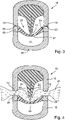
- FIG. 3 the instrument after Figure 1 and 2 when closed, in cross-section without fabric
- figure 4 the instrument after figure 3 with tissue held between the branches, in cross-section
- figure 5 a modified embodiment of the instrument, in a cross-sectional view in a slightly open state
- FIG. 6 a further modified embodiment of the instrument according to the invention in a cross-sectional view with the branches slightly open
- figure 7 the lower branch of the instrument figure 6 , in partial perspective representation
- figure 8 a plastic injection mold for producing an abutment for the instrument Figure 1 to 5 .
- the instrument 10 can be an instrument to be used openly, an instrument to be used laparoscopically or an instrument to be used endoscopically.
- the instrument 10 has two branches 12, 13 held, for example, on a flexible shaft 11 or on a rigid shaft, of which at least one of the branches, in the present exemplary embodiment the upper branch 12, is pivotably mounted to the other in the present example to be able to move the lower branch 13 towards and away from it.
- the pivotal movement about the hinge axis 14 is controlled by a mechanism which extends through the shaft 11 and is not illustrated in any more detail.
- the instrument 10 can also have two pivotally mounted branches that can be moved toward and away from each other.
- FIG 2 illustrates the instrument 10 figure 1 in cross-section, cut along the line II-II in figure 1 .
- the upper branch 12 can be formed, for example, by a metal part 14 which is U-shaped in cross-section on the outside and is either bare metal on the outside or else is electrically insulated, the end faces 5 of the legs of which serve as coagulation electrodes 15 , 16 .
- the coagulation electrodes 15, 16 can be continuously strip-shaped electrodes, they can also be interrupted by insulating sections.
- the upper branch 12 can also have another part, for example made of a non-conductive material such as plastic, into which the coagulation electrodes 15, 16 are embedded, for example in the form of sheet metal parts.
- the upper branch 12 is provided with a cutting electrode 17 which is formed, for example, by a thin sheet metal strip.
- the cutting electrode 17 is preferably held in an insulating body 18 approximately centrally between the coagulation electrodes 15, 16.
- the cutting electrode 17 is preferably arranged in an extension 19 of the insulating body 18 so that the two flat sides of the cutting electrode 19 are insulated. Between the extension 19 and the coagulation electrodes 15, 16 supporting legs of the upper branch 12 free spaces 20, 21 are formed, which serve to accommodate tissue.
- the lower branch 13 contains an abutment 22 which serves to hold biological tissue on the cutting electrode 17 during a cutting operation.
- the abutment 22 is a flexible body made of silicone, for example, whose thickness D M to be measured in a central region 23, in particular in the extension of the cutting electrode 17, is smaller than the width B to be measured transversely thereto.
- the abutment 22 consists of solid material. It preferably has no cavities.
- the abutment 22 adjoins a frame 25 with its peripheral surface 24 and is preferably firmly bonded to it there, e.g. by injection molding or gluing.
- the peripheral surface 24 is preferably unstructured, i.e. smooth except for traces of processing such as punched or fractured surfaces. However, it can also be structured in order to support the material connection between the abutment 22 and the frame 25, for example by means of a positive fit.
- the abutment 22 has a thickness D R on its edge adjoining the peripheral surface 24, which is preferably at least as large as the thickness D M in the middle Area 23.
- the thickness D R also corresponds to the thickness of the frame 25 to be measured in the same direction, so that the abutment 22 is flush with the frame 25 both on its upper side 26 and on its lower side 27 .
- the frame 25 is preferably made of metal, so that its upper side forms the coagulation electrodes 28, 29. These can merge into one another at the distal end of the respective branch 12 or 13 .
- the unit consisting of the abutment 22 and the frame 25 can be produced in an injection molding process, in which a prefabricated frame 25 is introduced into a corresponding injection mold, into which the plastic material of the abutment 22 is then introduced in order to be intimately attached to the peripheral surface 24 to connect the edge 25.
- the unit formed in this way is connected to the rest of the supporting part of the lower branches 13, which is formed by a U-shaped metal part 30 in the present embodiment.
- This can be bare metal on its outside or electrically insulated, for example with a plastic coating.
- the frame 25 can also be bare metal on its side pointing outwards, i.e. electrically conductive or alternatively provided with insulation.
- the frame 25 can be electrically conductively connected to the metal part 30 or also insulated from it.
- An interior space 31 is formed between the abutment 22 and the metal part 30, which can also be connected to the environment separately from the environment via suitable openings.
- FIG 3 illustrates the instrument 10 in the closed condition.
- the electrodes 15, 28 touch one another or are held at a small distance from one another by means of spacers (not shown in any more detail).
- the cutting electrode 17 stands on the abutment 22 and presses it into the free space 31 without the underside 27 of the abutment 22 touching the metal part 30 or any other part located in the free space 31. Because the abutment 22 is slim in cross-section, ie because its thickness D M is substantially less than its width B, the abutment 22 at the in figure 3 illustrated deformation essentially claimed to train. It is stretched. Likewise, the connection between its peripheral surface 24 and the frame 25 is essentially subjected to tension.
- the instrument 10 works as follows: As figure 4 illustrated, for the treatment of biological tissue 32 this is first taken between the branches 12, 13.
- the biological tissue 32 can be organ tissue, a blood vessel or other tissue.
- the branches 12, 13 moving towards one another grasp the tissue 32.
- the coagulation electrodes 15, 28, 16, 29 are subjected to coagulation voltage and the cutting electrode 17 is subjected to cutting voltage.
- the abutment 22 is how figure 2 shows, when the instrument 10 is closed, the cutting electrode 17 and the tissue 32 have been avoided and thus tensioned. However, the abutment forces the tissue 32 against the cutting electrode 17.
- the biological tissue 32 can penetrate into the free spaces 20, 21 on both sides of the extension 19.
- the coagulation electrodes 15, 28 and 16, 29 coagulate the tissue held between them and if it is a vessel, they fuse it, ie close at these points.
- the tissue subjected to a correspondingly higher cutting voltage by the cutting electrode 17 shrinks and separates itself, the abutment 22 holding the shrinking tissue to the cutting electrode 17.
- the abutment 22 can also be flat or as in the embodiments Figure 1 to 4 and concave, ie curved away from the cutting electrode 17 .
- desired spring characteristics ie path-force courses, can be set, which can be recorded when the instrument 10 is closed.
- the abutment 22 can have extensions 33, 34, 35 which overlap the frame 25 and thus prevent the coagulation electrodes 15, 16 from coming into direct contact with the coagulation electrodes 28, 29. Otherwise, the abutment 22 is also preferably flush with the frame 25 both on its upper side 26 and on its lower side 27 in this embodiment.
- the production of the abutment 22 is based on figure 8 be illustrated.
- a plastic injection mold 36 is provided, between the upper mold half 37 and the lower mold half 38 of which an engraving 39 is formed which defines the shape of the mold to be produced abutment.
- an engraving 39 is formed which defines the shape of the mold to be produced abutment.
- a central raised projection 40 is illustrated in the engraving 39, which reduces the thickness of the abutment 22 to be produced in the central region.
- the frame 25 is inserted into the engraving 39 with the plastic injection mold 36 open, after which the injection mold 36 is closed. Then liquid plastic is filled into the engraving 39 so that it completely fills the available space and rests against the inside of the frame 25 and adhesively connects to it. After the plastic has hardened, the plastic injection mold 36 can be opened and the abutment 22 can be removed.
- a cutting electrode 17 arranged between two pairs of electrodes is assigned an abutment 22 which is designed as a thin membrane.
- the thin membrane is stretched in a frame 25 to which it is held in a materially bonded manner with its peripheral surface.
- the peripheral surface is at an angle, preferably a right angle, to the coagulation electrodes 28, 29 formed by the top of the frame.
- the pressure force exerted by the membrane, with which the biological tissue 32 is pressed against the cutting electrode 17, is predominantly Membrane 22 existing tensile stress generated.
Landscapes
- Health & Medical Sciences (AREA)
- Surgery (AREA)
- Engineering & Computer Science (AREA)
- Life Sciences & Earth Sciences (AREA)
- Biomedical Technology (AREA)
- Otolaryngology (AREA)
- Nuclear Medicine, Radiotherapy & Molecular Imaging (AREA)
- Plasma & Fusion (AREA)
- Physics & Mathematics (AREA)
- Heart & Thoracic Surgery (AREA)
- Medical Informatics (AREA)
- Molecular Biology (AREA)
- Animal Behavior & Ethology (AREA)
- General Health & Medical Sciences (AREA)
- Public Health (AREA)
- Veterinary Medicine (AREA)
- Surgical Instruments (AREA)
Abstract
Description
- Die Erfindung betrifft ein elektrochirurgisches Instrument, das zur Dissektion oder zur Gewebefusion oder Gewebekoagulation insbesondere kombiniert mit der Gewebedissektion eingerichtet und geeignet ist.
- Die
JP 2004180843 A - Aus der
US 2004/0049185 A1 ist ein Koagulations- und Dissektionsinstrument mit elastischem Widerlager bekannt. Das Widerlager weist einen etwa quadratischen Querschnitt auf und stützt sich an seiner der Schneidelektrode gegenüber liegenden Seite an der ansonsten U-förmig ausgebildeten Branche zwischen ihren beiden Schenkeln ab. Die Flanken des Widerlagers liegen frei. - Die
US 2009/0234355 A1 offenbart ein Koagulations- und Dissektionsinstrument mit einer in einer Branche angeordneten Schneidelektrode und einem in der anderen Branche angeordneten beweglich gelagerten Widerlager. Diese ist federnd unterstützt, um der eindringenden Schneidelektrode ausweichen zu können. - Weitere Beispiele für elektrochirurgische Instrumente mit Koagulationselektroden, Schneidelektroden und den Schneidelektroden zugeordneten Widerlagern können der
EP 1 632 192 A1 und derEP 2 754 403 A2 entnommen werden. - Die Anforderungen an Koagulations- und Dissektionsinstrumente steigen in mehrerlei Hinsicht. Es gibt Miniaturisierungstendenzen sowie Anforderungen an Fertigungssicherheit und Fertigungspräzision.
- Davon ausgehend, ist es Aufgabe der Erfindung, ein Instrument zu schaffen, das in mindestens einer Hinsicht verbessert ist.
- Diese Aufgabe erfüllt das erfindungsgemäße Instrument nach Anspruch 1:
- Das erfindungsgemäße Instrument weist an einer Branche eine Schneidelektrode und an der anderen gegenüberliegenden Branche ein elastisches Widerlager auf. Das Widerlager ist in einem Rahmen gehalten, der von der betreffenden Branche selbst oder einem gesonderten Bauteil gebildet ist. Das Widerlager weist eine Umfangsfläche auf, die mit dem Rahmen zugfest verbunden ist. Der Rahmen fixiert das Widerlager wenigstens an zwei einander gegenüberliegenden Seiten. Vorzugsweise umschließt der Rahmen das Widerlager dreiseitig, d.h. an seinen beiden Flanken und an dem distalen Ende. Das Widerlager ist zumindest an seinen beiden langen Seiten oder Flanken und wahlweise auch an seinem distalen Ende mit dem Rahmen verbunden. In letzterem Fall verschließt das Widerlager den Rahmen komplett und lässt kein Material in den Bereich unterhalb des Widerlagers gelangen. Es ist aber auch möglich, die Membran an ihrem distalen Ende und/oder an ihrem proximalen Ende frei, d.h. nicht mit dem Rahmen verbunden, zu lassen.
- Dem Widerlager zugewandt weist der Rahmen eine Fläche auf, die mit der Umfangsfläche des Widerlagers verbunden ist. Die Verbindung ist zugfest, d.h. eine von dem Rand des Widerlagers zu seiner Mitte hin gerichtete Zugkraft löst das Widerlager nicht von dem Rahmen. Die Verbindung ist vorzugsweise spaltfrei, d.h. die Umfangsfläche des Widerlagers ist vollflächig mit dem Rahmen verbunden. Unter Zugbelastung hebt vorzugsweise kein Teil des Widerlagers von dem Rahmen ab. Eine Zugkraft kann entstehen, indem die Schneidelektrode sowie gegebenenfalls zwischen Schneidelektrode und Widerlager vorhandenes biologisches Gewebe beim Schließen der Branche auf das Widerlager drückt. Dieses wird dabei aus seiner Ruheposition ausgelenkt und gespannt. Dabei ist das Widerlager vorzugsweise so flexibel ausgebildet, dass durch die Deformation des Widerlagers hauptsächlich Zugspannungen entstehen, weswegen das Widerlager auch als "Membran" bezeichnet wird. Im bevorzugten Fall ist das Widerlager so gestaltet, dass es sich hinsichtlich seiner mechanischen Spannungen im nicht belasteten Zustand bei offenen Branchen und vorzugsweise auch im belasteten Zustand bei geschlossenen Branchen im sogenannten Membranzustand befindet, d.h. die im Material des Widerlagers vorhandenen Zugspannungen sind zumindest näherungsweise überall gleich.
- Die zugfeste Verbindung zwischen den Widerlager und dem Rahmen ist vorzugsweise eine stoffschlüssige Verbindung, gegebenenfalls eine rein stoffschlüssige Verbindung. Sie kann auf einfachste Weise zustande kommen, indem die Membran im Spritzgussverfahren erzeugt wird, wobei der Rahmen einen Teil der Spritzgussform bildet, d.h. den Materialfluss des noch flüssigen Widerlagers an der Umfangfläche des entstehenden Widerlagers begrenzt. Der Rahmen besteht vorzugsweise aus Metall. Das Widerlager besteht vorzugsweise aus flexiblem Kunststoff beispielsweise einem Silikonkunstoff. Die Haftung zwischen der Umfangsfläche der Membran und dem Rahmen kann durch entsprechende Oberflächengestaltung der der Membran zugewandten Fläche des Rahmens, zum Beispiel durch eine Aufrauhung, erhöht werden. Außerdem kann die Oberfläche des Rahmens zur Verbesserung der Haftung des Widerlagers vollständig oder abschnittsweise aktiviert werden. Dazu kann die Oberfläche stellenweise oder ganz einem CVD- oder PVD-Beschichtungsverfahren unterzogen werden. Ist der Rahmen ein Stanzteil, können beim Stanzen entstehenden Oberflächenunebenheiten des Rahmens zur Verbesserung der Haftung zwischen dem Rahmen und der Membran genutzt werden.
- Die zugfeste Verbindung zwischen dem Widerlager und dem Rahmen kann durch Formschluss zwischen Widerlager und Rahmen unterstützt werden, beispielsweise indem der Rahmen entlang seiner dem Widerlager zugewandten Fläche Formschlussstrukturen aufweist, wie beispielsweise Öffnungen, Ausschnitte oder dergleichen.
- Vorzugsweise ist das Widerlager in dem Rahmen unterstützungsfrei gehalten. Insbesondere liegt es an keiner der Eindringrichtung der Schneidelektrode entgegen gerichteten Fläche auf. Mit anderen Worten, die der Schneidelektrode zugewandte freie Oberseite ist ebenso groß wie die von der Schneidelektrode abgewandt angeordnete freie Unterseite des Widerlagers. Infolge dieser Anordnung wird zwischen den Branchen gefasstes biologisches Gewebe besonders sanft und gleichmäßig an die Schneidelektrode gedrückt, sodass das zwischen der Schneidelektrode und dem Widerlager gefasste Gewebe elektrisch geschnitten, nicht aber mechanisch gequetscht wird. Der Trennvorgang ist ein rein elektrischer. Dies lässt sich sowohl bei großen Bauformen des Instruments als auch bei miniaturisierten Bauformen desselben erreichen.
- Das Widerlager besteht vorzugsweise aus einem elektrisch isolierenden Kunststoff, wie z.B. Silicon. Es kann aber auch aus einem Kunststoff bestehen, der intrinsisch oder extrinsisch, d.h. durch Einlagerung elektrisch leitfähiger Stoffe oder Partikel elektrisch leitfähig ist. Dadurch kann während des Stromdurchflusses durch das Gewebe eine zusätzliche thermische Wirkung entstehen.
- Vorzugsweise weist das Widerlager zwei Flanken auf, die in konstantem Abstand zueinander angeordnet sind. Der Abstand kann aber auch in distaler Richtung abnehmen.
- Das Widerlager kann in seinem mittleren Bereich, der im geschlossenen Zustand die Schneidelektrode berührt, eine Dicke aufweisen, die höchsten so groß ist, wie die Dicke am Rand des Widerlagers. Vorzugsweise ist die Dicke im mittleren Bereich sogar geringer als am Rand des Widerlagers. Dadurch wird ein Hauptvorteil der Erfindung gefördert. Beim Schließen des Instruments wird das Widerlager vorzugsweise auf Dehnung beanstandet und weniger auf Stauchung oder Biegung wie es beim Stand der Technik häufig der Fall war. Damit kann sich das membranartige Widerlager auch an inhomogenes Gewebe gut anpassen und dieses in sanfter Anlage an der Schneidelektrode halten. Es ist aber auch möglich, die Dicke des Widerlagers in der Mitte unterhalb der Schneidelektrode größer zu machen, als am Rand (an der Flanke bzw. Umfangsfläche).
- Das Widerlager kann in Ruheposition von der Schneidelektrode weg oder auf diese hin gewölbt sein. Damit lassen sich verschiedene Federcharakteristika einstellen, um beim Einfedern, d.h. beim Schließen des Instruments, einen gewünschten Verlauf der Andruckkraft des Gewebes an die Schneidelektrode zu erzielen.
- Bei einer vorteilhaften Ausführungsform schließt das Widerlager sowohl an seiner Oberseite als auch an seiner Unterseite bündig mit dem Rahmen ab. Dies erleichtert die Fertigung des Instruments, insbesondere die Erzeugung des Widerlagers in dem Rahmen.
- Das Widerlager kann einen oder mehrere sich auf den Rahmen erstreckender Abschnitte aufweisen. Vorzugsweise ist ein solcher Abschnitt wenigstens an dem distalen Ende des Widerlagers bzw. der es enthaltenden Branche angeordnet. Solche Abschnitte können als Abstandshalter der Branchen dienen und verhindern, dass sich diese beim Schließen unmittelbar berühren. Abgesehen von diesen Abschnitten ist es aber vorteilhaft, wenn das Widerlager wenigstens ansonsten an der Oberseite und der Unterseite bündig mit dem Rahmen abschließt.
- Weitere Einzelheiten vorteilhafter Ausführungsformen der Erfindung ergeben sich aus der Zeichnung, der zugehörigen Beschreibung sowie aus Ansprüchen. Es zeigen:
-
Figur 1 das erfindungsgemäße Instrument, in geschlossenem Zustand, -
Figur 2 die obere und untere Branche des Instruments nachFigur 1 , in geöffnetem Zustand, im Querschnitt, -
Figur 3 das Instrument nachFigur 1 und 2 in geschlossenem Zustand, im Querschnitt ohne Gewebe, -
Figur 4 das Instrument nachFigur 3 mit zwischen den Branchen gefasstem Gewebe, in Querschnittsdarstellung, -
Figur 5 eine abgewandelte Ausführungsform des Instruments, in Querschnittsdarstellung in leicht geöffnetem Zustand, -
Figur 6 eine weitere abgewandelte Ausführungsform des erfindungsgemäßen Instruments in Querschnittsdarstellung bei leicht geöffneten Branchen, -
Figur 7 die untere Branche des Instruments nachFigur 6 , in ausschnittsweiser Perspektivdarstellung und -
Figur 8 eine Kunststoff-Spritzgussform zur Herstellung eines Widerlagers für das Instrument nachFigur 1 bis 5 . - In
Figur 1 ist ein Instrument veranschaulicht, das zur Gewebefusion und Dissektion eingerichtet ist. Bei dem Instrument 10 kann es sich um ein offenchirurgisch einzusetzendes Instrument, um ein laparoskopisch einzusetzendes Instrument oder auch um ein endoskopisch einzusetzendes Instrument handeln. Das Instrument 10 weist zwei beispielsweise an einem flexiblen Schaft 11 oder auch an einen steifen Schaft gehaltenen Branchen 12, 13 auf, von denen mindestens eine der Branchen, im vorliegenden Ausführungsbeispiel die obere Branche 12, schwenkbar gelagert ist, um auf die andere im vorliegenden Beispiel die untere Branche 13 hin und von dieser weg bewegt werden zu können. Die Schwenkbewegung um die Scharnierachse 14 wird von einem nicht weiter veranschaulichten sich durch den Schaft 11 erstreckenden Mechanismus gesteuert. - Alternativ kann das Instrument 10 auch zwei schwenkbar gelagerte Branchen aufweisen, die aufeinander zu und voneinander weg beweglich sind.
-
Figur 2 veranschaulicht das Instrument 10 nachFigur 1 im Querschnitt, geschnitten entlang der Linie II-II inFigur 1 . Die obere Branche 12 kann zum Beispiel durch ein im Querschnitt U-förmiges außen metallisch blankes oder auch elektrisch isoliertes Metallteil 14 gebildet sein, dessen Schenkelstirnseiten 5 als Koagulationselektroden 15, 16 dienen. Die Koagulationselektroden 15, 16 können durchgehend streifenförmige Elektroden sein, sie können auch durch isolierende Abschnitte unterbrochen sein. Die obere Branche 12 kann anstelle eines Metallteils 14 auch ein anderes beispielsweise aus einem nicht leitendem Material, wie zum Beispiel Kunststoff bestehendes Teil aufweisen, in das die Koagulationselektroden 15, 16 beispielsweise in Gestalt von Blechteilen eingelassen sind. - Die obere Branche 12 ist mit einer Schneidelektrode 17 versehen, die zum Beispiel durch einen dünnen Blechstreifen gebildet ist. Vorzugsweise ist die Schneidelektrode 17 in einen Isolierkörper 18 etwa mittig zwischen den Koagulationselektroden 15, 16 gehalten. Die Schneidelektrode 17 ist vorzugsweise in einem Fortsatz 19 des Isolierkörpers 18 angeordnet, sodass die beiden Flachseiten der Schneidelektrode 19 isoliert sind. Zwischen dem Fortsatz 19 und den die Koagulationselektroden 15, 16 tragenden Schenkeln der oberen Branche 12 sind Freiräumen 20, 21 ausgebildet, die zur Gewebeaufnahme dienen.
- Die untere Branche 13 enthält ein Widerlager 22, das dazu dient, biologisches Gewebe während eines Schneidvorgangs an der Schneidelektrode 17 zu halten. Das Widerlager 22 ist ein flexibler beispielsweise aus Silikon bestehender Körper, dessen in einem mittleren Bereich 23 insbesondere in Verlängerung der Schneidelektrode 17 zu messende Dicke DM kleiner ist als die quer dazu zu messende Breite B. Das Widerlager 22 besteht aus Vollmaterial. Es weist vorzugsweise keinerlei Hohlräume auf.
- Seitlich schließt das Widerlager 22 mit seiner Umfangsfläche 24 an einen Rahmen 25 an und ist dort zugfest vorzugsweise stoffschlüssig mit diesem verbunden, z.B. durch Anspritzen oder Kleben. Die Umfangsfläche 24 ist vorzugsweise unstrukturiert, d.h. bis auf Bearbeitungsspuren wie Stanz- oder Bruchflächen, glatt. Sie kann jedoch auch strukturiert sein, um die stoffliche Verbindung zwischen dem Widerlager 22 und dem Rahmen 25 zum Beispiel durch Formschluss zu unterstützen.
- Das Widerlager 22 weist an seinen an die Umfangsfläche 24 angrenzenden Rand eine Dicke DR auf, die vorzugsweise mindestens so groß ist wie die Dicke DM im mittleren Bereich 23. Die Dicke DR entspricht dabei außerdem der in gleiche Richtung zu messende Dicke des Rahmens 25, sodass das Widerlager 22 sowohl an seiner Oberseite 26 als auch an seiner Unterseite 27 bündig mit dem Rahmen 25 abschließt.
- Der Rahmen 25 besteht vorzugsweise aus Metall, sodass seine Oberseite die Koagulationselektroden 28, 29 bildet. Diese können an dem distalen Ende der jeweiligen Branche 12 bzw. 13 ineinander übergehen.
- Die aus dem Widerlager 22 und dem Rahmen 25 bestehende Einheit kann in einem Spritzgussverfahren hergestellt werden, bei dem ein vorgefertigter Rahmen 25 in eine entsprechende Spritzgussform eingeführt wird, in die dann das Kunststoffmaterial des Widerlagers 22 eingeführt wird, um sich an der Umfangsfläche 24 innig mit dem Rand 25 zu verbinden. Die so gebildete Einheit ist mit dem übrigen tragenden Teil der unteren Branchen 13 verbunden, der im vorliegenden Ausführungsfall durch ein U-förmiges Metallteil 30 gebildet wird. Dieses kann an seiner Außenseite metallisch blank oder elektrisch isoliert zum Beispiel mit einem Kunststoffüberzug versehen sein. Auch der Rahmen 25 kann an seiner nach außen weisenden Seite metallisch blank, d.h. elektrisch leitende oder alternativ mit einer Isolierung versehen sein, Der Rahmen 25 kann mit dem Metallteil 30 elektrisch leitend verbunden oder auch gegen dieses isoliert sein. Zwischen dem Widerlager 22 und dem Metallteil 30 ist ein Innenraum 31 ausgebildet, der von der Umgebung getrennt über geeignete Öffnungen auch mit diese verbunden sein kann.
-
Figur 3 veranschaulicht das Instrument 10 in geschlossenem Zustand. Die Elektroden 15, 28 berühren einander oder sind über nicht weiter dargestellte Abstandshalter in geringem Abstand zueinander gehalten. Gleiches gilt für die Koagulationselektroden 16, 29. Die Schneidelektrode 17 steht auf dem Widerlager 22 und drückt dieses in den Freiraum 31 hinein, ohne dass die Unterseite 27 des Widerlagers 22 das Metallteil 30 oder irgendein anderes in dem Freiraum 31 befindliches Teil berührt. Weil das Widerlager 22 im Querschnitt schlank ist, d.h. weil seine Dicke DM wesentliche geringer ist als seine Breite B, wird das Widerlager 22 bei der inFigur 3 veranschaulichten Deformation im Wesentlichen auf Zug beansprucht. Es wird gedehnt. Ebenso wird die Verbindung zwischen seiner Umfangsfläche 24 und dem Rahmen 25 im Wesentlichen auf Zug beansprucht. - Das Instrument 10 arbeitet wie folgt:
WieFigur 4 veranschaulicht, wird zur Behandlung von biologischem Gewebe 32 dieses zunächst zwischen den Branchen 12, 13 gefasst. Das biologische Gewebe 32 kann Organgewebe, ein Blutgefäß oder auch anderweitiges Gewebe sein. Die aufeinander zu bewegten Branchen 12, 13 fassen das Gewebe 32. Gleichzeitig oder in zeitlicher Reihenfolge werden die Koagulationselektroden 15, 28, 16, 29 mit Koagulationsspannung und die Schneidelektrode 17 mit Schneidspannung beaufschlagt. Das Widerlager 22 ist, wieFigur 2 zeigt, beim Schließen des Instruments 10 der Schneidelektrode 17 und dem Gewebe 32 ausgewichen und dadurch gespannt worden. Das Widerlager drängt das Gewebe 32 dabei aber an die Schneidelektrode 17. Das biologische Gewebe 32 kann zu beiden Seiten des Fortsatzes 19 in die Freiräume 20,21 eindringen. Die Koagulationselektroden 15, 28 sowie 16, 29 koagulieren das zwischen ihnen gefasste Gewebe und falls es sich um ein Gefäß handelt, fusionieren sie es, d.h. schließen an diesen Stellen. Das von der Schneidelektrode 17 mit einer entsprechend höheren Schneidspannung beaufschlagt Gewebe schrumpft und trennt sich, wobei das Widerlager 22 das schrumpfende Gewebe sich an der Schneidelektrode 17 hält. - An der insoweit beschriebenen Erfindung sind Abwandlungen möglich. Beispielsweise kann, wie
Figur 5 veranschaulicht, das Widerlager 22 zu der Schneidelektrode 17 hin konvex gewölbt sein. Dies führt dazu, dass beim Schließen des Instruments 10 zunächst die Wölbung des Widerlagers 22 überwunden werden muss, wodurch ein gewisser Schnappeffekt auftreten kann. Alternativ kann das Widerlager 22 auch vollständig eben sein. Ansonsten gilt die Beschreibung derFiguren 1 bis 4 für die Ausführungsform des Instruments 10 nachFigur 5 entsprechend. - Das Widerlager 22 kann auch eben oder wie bei den Ausführungsformen nach
Figur 1 bis 4 sowie konkav, d.h. von der Schneidelektrode 17 weg gewölbt ausgebildet sein. Mit dem Verlauf der Dicke von der Mitte 23 zum Rand des Widerlagers 22 sowie mit der Wölbung lassen sich gewünschte Federkennlinien, d.h. Weg-Kraft-Verläufe einstellen, die beim Schließen des Instruments 10 zu verzeichnen sind. - Bei allen vorbeschriebenen Ausführungsformen kann das Widerlager 22 Fortsätze 33, 34, 35 aufweisen, die den Rahmen 25 übergreifen und somit eine direkte Berührung der Koagulationselektroden 15, 16 mit den Koagulationselektroden 28, 29 verhindern. Im Übrigen schließt das Widerlager 22 jedoch auch bei dieser Ausführungsform vorzugsweise bündig sowohl an seiner Oberseite 26 als auch an seiner Unterseite 27 bündig mit dem Rahmen 25 ab.
- Die Herstellung des Widerlagers 22 soll anhand von
Figur 8 veranschaulicht werden. Es wird dazu eine Kunststoff-Spritzgussform 36 bereitgestellt, zwischen deren oberer Formhälfte 37 und deren unterer Formhälfte 38 eine Gravur 39 ausgebildet ist, die die Form des zu erzeugenden Widerlagers festlegt. InFigur 8 ist in der Gravur 39 ein mittlerer erhabener Vorsprung 40 veranschaulicht, der die Dicke des zu erzeugenden Widerlagers 22 im mittleren Beriech reduziert. - Zur Herstellung des Widerlagers 22 wird bei geöffneter Kunststoff-Spritzgussform 36 der Rahmen 25 in die Gravur 39 eingelegt, wonach die Spritzgussform 36 geschlossen wird. Danach wird flüssiger Kunststoff in die Gravur 39 eingefüllt, sodass dieser den vorhandenen Raum restlos füllt und sich an die Innenseite des Rahmens 25 anlegt und adhäsiv mit dieser verbindet. Nach dem Aushärten des Kunststoffs kann die Kunststoff-Spritzgussform 36 geöffnet und das Widerlager 22 entnommen werden.
- Bei einem erfindungsgemäßen Instrument 10, das vorzugsweise zur Gewebefusion und Dissektion einsetzbar ist, ist einer zwischen zwei Elektrodenpaaren angeordneten Schneidelektrode 17 ein Widerlager 22 zugeordnet, das als dünne Membran ausgebildet ist. Die dünne Membran ist in einem Rahmen 25 gespannt, an dem sie mit ihrer Umfangsfläche stoffschlüssig gehalten ist. Die Umfangsfläche steht dabei in einem Winkel, vorzugsweise einem rechten Winkel, zu dem von der Rahmenoberseite gebildeten Koagulationselektroden 28, 29. Die von der Membran ausgeübte Andruckkraft, mit der das biologische Gewebe 32 an die Schneidelektrode 17 angedrückt wird, wird überwiegend von der in der Membran 22 vorhandenen Zugspannung erzeugt.
-
- 10
- Instrument
- 11
- Schaft
- 12
- obere Branche
- 13
- untere Branche
- 14
- Metallteil
- 15, 16
- Koagulationselektroden der oberen Branche 12
- 17
- Schneidelektrode
- 18
- Isolierkörper
- 19
- Fortsatz des Isolierkörpers
- 20, 21
- Freiräume
- 22
- Widerlager
- 23
- mittlerer Bereich des Widerlagers 22
- 24
- Umfangsfläche des Widerlagers
- 25
- Rahmen
- 26
- Oberseite des Widerlagers 22
- 27
- Unterseite des Widerlagers
- 28, 29
- Koagulationselektroden der unteren Branche 13
- 30
- Metallteil
- 31
- Freiraum
- 32
- biologisches Gewebe
- 33 - 35
- Fortsätze
- 36
- Kunststoff-Spritzgussform
- 37
- obere Formhälfte
- 38
- untere Formhälfte
- 39
- Gravur
- 40
- Vorsprung
Claims (12)
- Instrument (10), insbesondere zur Dissektion oder zur kombinierten Gewebefusion oder -koagulation und Gewebedissektion,
mit zwei Branchen (12, 13), von denen wenigstens eine auf die andere hin und von dieser weg beweglich gelagert ist,
mit einer Schneidelektrode (17), die an einer der Branchen (12) angeordnet ist,
mit einem der Schneidelektrode (17) zugeordneten elastischen Widerlager (22), das an der anderen der Branchen (13) angeordnet und in einem Rahmen (25) gehalten ist, an dem es mit seiner Umfangsfläche (24) anliegend angeordnet ist,
dadurch gekennzeichnet,
dass das Widerlager (22) an seiner Umfangsfläche (24) mit dem Rahmen (25) zugfest verbunden ist. - Instrument nach Anspruch 1, dadurch gekennzeichnet,
dass das Widerlager (22) in dem Rahmen (25) unterstützungsfrei gehalten ist. - Instrument nach einem der vorstehenden Ansprüche,
dadurch gekennzeichnet, dass das Widerlager (22) mit dem Rahmen (25) stoffschlüssig verbunden ist. - Instrument nach einem der vorstehenden Ansprüche,
dadurch gekennzeichnet, dass das Widerlager (22) eine Kunststoffmembrane ist, deren in Bewegungsrichtung der wenigstens einen beweglichen Branche (12) zu messende Dicke (DM) in einem mittleren Bereich (23), auf den die Schneidelektrode (17) in Betrieb aufsetzt, höchstens so groß ist, wie an der Umfangsfläche (24). - Instrument nach einem der vorstehenden Ansprüche,
dadurch gekennzeichnet, dass das Widerlager (22) eine Kunststoffmembrane ist, deren in Bewegungsrichtung der wenigstens einen beweglichen Branche (12) zu messende Dicke (DM) in einem mittleren Bereich (23), auf den die Schneidelektrode (17) in Betrieb aufsetzt, eine geringere Dicke aufweist, als an allen anderen Stellen. - Instrument nach einem der vorstehenden Ansprüche,
dadurch gekennzeichnet, dass das Widerlager (22) eine Kunststoffmembrane ist, deren in Bewegungsrichtung der wenigstens einen beweglichen Branche (12) zu messende Dicke (DM) in einem mittleren Bereich (23), auf den die Schneidelektrode (17) in Betrieb aufsetzt, eine größere Dicke aufweist, als an allen anderen Stellen. - Instrument nach einem der vorstehenden Ansprüche,
dadurch gekennzeichnet, dass das Widerlager (22) im Ruhezustand an seiner der Schneidelektrode (17) zugewandten Seite (26) konkav oder konvex gewölbt ausgebildet ist. - Instrument nach einem der vorstehenden Ansprüche,
dadurch gekennzeichnet, dass das Widerlager (22) im die von dem Rahmen (25) umgrenzte Öffnung ganz verschließend ausgebildet und angeordnet ist. - Instrument nach einem der vorstehenden Ansprüche,
dadurch gekennzeichnet, dass das Widerlager (22) sowohl an seiner Oberseite (26) als auch an seiner Unterseite (27) bündig mit dem Rahmen (25) abschließend ausgebildet ist. - Instrument nach einem der vorstehenden Ansprüche,
dadurch gekennzeichnet, dass das Widerlager (22) wenigstens einen sich auf den Rahmen (25) erstreckenden Abschnitt (33, 34, 35) aufweist. - Instrument nach Anspruch 10, dadurch gekennzeichnet, dass der Abschnitt (34) an dem distalen Ende der das Widerlager (22) enthaltenden Branche (13) angeordnet ist.
- Verfahren zur Herstellung eines Widerlagers für ein Instrument nach Anspruch 1, mit folgenden Schritten:Bereitstellung einer Kunststoff-Spritzgussform (36) mit einer Gravur (39) zur Aufnahme des Rahmens (25),Anordnen des Rahmens (25) in der Gravur (39),Einleiten von Kunststoff in die Gravur (39), so dass dieser sich an den Rahmen (25) anlegt und adhäsiv verbindet,Erstarren lassen des Kunststoffs so dass dieser zusammen mit dem Rahmen (25) das Widerlager (22) bildet, undÖffnen der Spritzgussform (36) und Entnehmen des Widerlagers (22).
Priority Applications (7)
| Application Number | Priority Date | Filing Date | Title |
|---|---|---|---|
| EP21151169.6A EP4026507A1 (de) | 2021-01-12 | 2021-01-12 | Dissektionsinstrument |
| JP2021209163A JP2022108265A (ja) | 2021-01-12 | 2021-12-23 | 切断器具 |
| BR102021026819-0A BR102021026819A2 (pt) | 2021-01-12 | 2021-12-30 | Instrumento de corte |
| KR1020220002529A KR20220102119A (ko) | 2021-01-12 | 2022-01-07 | 절단 기구 |
| US17/572,305 US12551267B2 (en) | 2021-01-12 | 2022-01-10 | Cutting instrument |
| CN202210025453.4A CN114762620B (zh) | 2021-01-12 | 2022-01-11 | 切割器械 |
| JP2025234454A JP2026026364A (ja) | 2021-01-12 | 2025-12-05 | 方法 |
Applications Claiming Priority (1)
| Application Number | Priority Date | Filing Date | Title |
|---|---|---|---|
| EP21151169.6A EP4026507A1 (de) | 2021-01-12 | 2021-01-12 | Dissektionsinstrument |
Publications (1)
| Publication Number | Publication Date |
|---|---|
| EP4026507A1 true EP4026507A1 (de) | 2022-07-13 |
Family
ID=74180939
Family Applications (1)
| Application Number | Title | Priority Date | Filing Date |
|---|---|---|---|
| EP21151169.6A Pending EP4026507A1 (de) | 2021-01-12 | 2021-01-12 | Dissektionsinstrument |
Country Status (6)
| Country | Link |
|---|---|
| US (1) | US12551267B2 (de) |
| EP (1) | EP4026507A1 (de) |
| JP (2) | JP2022108265A (de) |
| KR (1) | KR20220102119A (de) |
| CN (1) | CN114762620B (de) |
| BR (1) | BR102021026819A2 (de) |
Cited By (1)
| Publication number | Priority date | Publication date | Assignee | Title |
|---|---|---|---|---|
| WO2024224220A1 (en) * | 2023-04-28 | 2024-10-31 | Covidien Lp | Surgical end effector assemblies and surgical instruments for energy-based tissue cutting |
Families Citing this family (3)
| Publication number | Priority date | Publication date | Assignee | Title |
|---|---|---|---|---|
| AU2022213445A1 (en) * | 2021-02-01 | 2023-07-20 | Bolder Surgical, Llc | E-cut sealer-divider |
| WO2025259576A1 (en) * | 2024-06-12 | 2025-12-18 | Gyrus Acmi, Inc. D/B/A Olympus Surgical Technologies America | Overmolded standoff wedges |
| EP4717214A1 (de) * | 2024-09-27 | 2026-04-01 | Erbe Elektromedizin GmbH | Gewebeversiegelungsinstrument |
Citations (7)
| Publication number | Priority date | Publication date | Assignee | Title |
|---|---|---|---|---|
| US20040049185A1 (en) | 2002-07-02 | 2004-03-11 | Gyrus Medical, Inc. | Bipolar electrosurgical instrument for cutting desiccating and sealing tissue |
| JP2004180843A (ja) | 2002-12-02 | 2004-07-02 | Olympus Corp | 医療器械 |
| EP1632192A1 (de) | 2004-09-02 | 2006-03-08 | Sherwood Services AG | Instrument zur Gefäßversiegelung mit elektrischem Schneidmechanismus |
| US20090234355A1 (en) | 2008-03-13 | 2009-09-17 | Gyrus Medical Limited | Surgical instrument |
| EP2754403A2 (de) | 2013-01-10 | 2014-07-16 | Covidien LP | Chirurgische Zange |
| EP3132765A1 (de) * | 2015-08-21 | 2017-02-22 | Erbe Elektromedizin GmbH | Koagulations- und dissektionsinstrument mit verbesserter bedienung |
| EP3138522A1 (de) * | 2015-09-03 | 2017-03-08 | Erbe Elektromedizin GmbH | Instrument zum fassen, trennen und/oder koagulieren von biologischem gewebe |
Family Cites Families (6)
| Publication number | Priority date | Publication date | Assignee | Title |
|---|---|---|---|---|
| RU53884U1 (ru) | 2005-07-04 | 2006-06-10 | Артур Факилевич Аглиуллин | Электрохирургические щипцы |
| US8702694B2 (en) | 2005-11-23 | 2014-04-22 | Covidien Lp | Auto-aligning ablating device and method of use |
| US10039597B2 (en) | 2011-10-31 | 2018-08-07 | Boston Scientific Scimed, Inc. | Surgical cutting instrument and related methods |
| IL230567A0 (en) | 2014-01-21 | 2014-04-30 | E K D D S Ltd | Method and system for endophyll implantation in the eye |
| PL2959854T3 (pl) * | 2014-06-25 | 2018-07-31 | Erbe Elektromedizin Gmbh | Instrument chirurgiczny |
| US11058429B2 (en) * | 2019-06-24 | 2021-07-13 | Covidien Lp | Load sensing assemblies and methods of manufacturing load sensing assemblies |
-
2021
- 2021-01-12 EP EP21151169.6A patent/EP4026507A1/de active Pending
- 2021-12-23 JP JP2021209163A patent/JP2022108265A/ja active Pending
- 2021-12-30 BR BR102021026819-0A patent/BR102021026819A2/pt unknown
-
2022
- 2022-01-07 KR KR1020220002529A patent/KR20220102119A/ko active Pending
- 2022-01-10 US US17/572,305 patent/US12551267B2/en active Active
- 2022-01-11 CN CN202210025453.4A patent/CN114762620B/zh active Active
-
2025
- 2025-12-05 JP JP2025234454A patent/JP2026026364A/ja active Pending
Patent Citations (8)
| Publication number | Priority date | Publication date | Assignee | Title |
|---|---|---|---|---|
| US20040049185A1 (en) | 2002-07-02 | 2004-03-11 | Gyrus Medical, Inc. | Bipolar electrosurgical instrument for cutting desiccating and sealing tissue |
| JP2004180843A (ja) | 2002-12-02 | 2004-07-02 | Olympus Corp | 医療器械 |
| EP1632192A1 (de) | 2004-09-02 | 2006-03-08 | Sherwood Services AG | Instrument zur Gefäßversiegelung mit elektrischem Schneidmechanismus |
| US20090234355A1 (en) | 2008-03-13 | 2009-09-17 | Gyrus Medical Limited | Surgical instrument |
| EP2754403A2 (de) | 2013-01-10 | 2014-07-16 | Covidien LP | Chirurgische Zange |
| EP3132765A1 (de) * | 2015-08-21 | 2017-02-22 | Erbe Elektromedizin GmbH | Koagulations- und dissektionsinstrument mit verbesserter bedienung |
| EP3138522A1 (de) * | 2015-09-03 | 2017-03-08 | Erbe Elektromedizin GmbH | Instrument zum fassen, trennen und/oder koagulieren von biologischem gewebe |
| US20170065331A1 (en) * | 2015-09-03 | 2017-03-09 | Erbe Elektromedizin Gmbh | Instrument for Grasping, Dissecting and/or Coagulating Biological Tissue |
Cited By (1)
| Publication number | Priority date | Publication date | Assignee | Title |
|---|---|---|---|---|
| WO2024224220A1 (en) * | 2023-04-28 | 2024-10-31 | Covidien Lp | Surgical end effector assemblies and surgical instruments for energy-based tissue cutting |
Also Published As
| Publication number | Publication date |
|---|---|
| CN114762620B (zh) | 2025-04-25 |
| KR20220102119A (ko) | 2022-07-19 |
| JP2026026364A (ja) | 2026-02-16 |
| US20220218408A1 (en) | 2022-07-14 |
| US12551267B2 (en) | 2026-02-17 |
| CN114762620A (zh) | 2022-07-19 |
| JP2022108265A (ja) | 2022-07-25 |
| BR102021026819A2 (pt) | 2022-07-19 |
Similar Documents
| Publication | Publication Date | Title |
|---|---|---|
| EP4026507A1 (de) | Dissektionsinstrument | |
| EP3138522B1 (de) | Instrument zum fassen, trennen und/oder koagulieren von biologischem gewebe | |
| EP1330867B1 (de) | Betätigungselement und verfahren zu seiner herstellung | |
| EP1090431B1 (de) | Piezoelektrischer aktor | |
| DE19503702B4 (de) | Flüssigkeits- und gasdicht gekapselter Schalter, insbesondere für elektrochirurgische Instrumente | |
| DE3015634C2 (de) | Druckschalter mit einer Anzeigetafel | |
| EP1986733B2 (de) | Vorrichtung mit flexiblem mehrschichtsystem zur kontaktierung oder elektrostimulation von lebenden gewebezellen oder nerven | |
| EP2959854A1 (de) | Chirurgisches Instrument | |
| WO2016180841A1 (de) | Leiterplattenmodul mit durchgehender aussparung sowie diesbezügliche schallwandleranordnung sowie herstellungsverfahren | |
| EP3049008B1 (de) | Hf-chirurgisches instrument | |
| DE68920152T2 (de) | Verbindungsbleche, verbindungsblechgelenke und verbindungsblechstrukturen. | |
| EP4193419A1 (de) | Gehäuse für ein batteriemodul zur aufnahme von batteriezellen | |
| DE3329287C2 (de) | Implantierbare Knochenplatte | |
| DE102013013402A1 (de) | Biegeelementanordnung sowie deren Verwendung | |
| EP1110253A1 (de) | Piezoaktor mit verbesserter wärmeableitung | |
| EP2047530A1 (de) | Federelement sowie piezoaktor mit dem federelement | |
| EP3297559B1 (de) | Elektrochirurgisches koagulationsinstrument | |
| WO2018015106A1 (de) | Versteifter kontaktstab | |
| EP4263907A2 (de) | Anordnung elektrochemischer zellen | |
| EP1747762B1 (de) | Koagulationsklemme für chirurgische Zwecke | |
| EP1142039B1 (de) | Piezoaktuatorisches kippelement | |
| DE3333685A1 (de) | Elektrischer flachschalter | |
| EP2636081B1 (de) | Aktoreinheit und verfahren zur fertigung derselben | |
| DE10219401B4 (de) | Wenigstens eine einzige Mehrfachtastenanordnung aufweisende Tastatur | |
| DE102016214329A1 (de) | Ventilblockaggregat |
Legal Events
| Date | Code | Title | Description |
|---|---|---|---|
| PUAI | Public reference made under article 153(3) epc to a published international application that has entered the european phase |
Free format text: ORIGINAL CODE: 0009012 |
|
| STAA | Information on the status of an ep patent application or granted ep patent |
Free format text: STATUS: THE APPLICATION HAS BEEN PUBLISHED |
|
| AK | Designated contracting states |
Kind code of ref document: A1 Designated state(s): AL AT BE BG CH CY CZ DE DK EE ES FI FR GB GR HR HU IE IS IT LI LT LU LV MC MK MT NL NO PL PT RO RS SE SI SK SM TR |
|
| STAA | Information on the status of an ep patent application or granted ep patent |
Free format text: STATUS: REQUEST FOR EXAMINATION WAS MADE |
|
| 17P | Request for examination filed |
Effective date: 20221216 |
|
| RBV | Designated contracting states (corrected) |
Designated state(s): AL AT BE BG CH CY CZ DE DK EE ES FI FR GB GR HR HU IE IS IT LI LT LU LV MC MK MT NL NO PL PT RO RS SE SI SK SM TR |
|
| STAA | Information on the status of an ep patent application or granted ep patent |
Free format text: STATUS: EXAMINATION IS IN PROGRESS |
|
| 17Q | First examination report despatched |
Effective date: 20250603 |