EP4026412A1 - Work vehicle - Google Patents
Work vehicle Download PDFInfo
- Publication number
- EP4026412A1 EP4026412A1 EP20860312.6A EP20860312A EP4026412A1 EP 4026412 A1 EP4026412 A1 EP 4026412A1 EP 20860312 A EP20860312 A EP 20860312A EP 4026412 A1 EP4026412 A1 EP 4026412A1
- Authority
- EP
- European Patent Office
- Prior art keywords
- positioning device
- stay
- bar
- mounting stay
- base
- Prior art date
- Legal status (The legal status is an assumption and is not a legal conclusion. Google has not performed a legal analysis and makes no representation as to the accuracy of the status listed.)
- Pending
Links
Images





Classifications
-
- B—PERFORMING OPERATIONS; TRANSPORTING
- B60—VEHICLES IN GENERAL
- B60R—VEHICLES, VEHICLE FITTINGS, OR VEHICLE PARTS, NOT OTHERWISE PROVIDED FOR
- B60R11/00—Arrangements for holding or mounting articles, not otherwise provided for
-
- B—PERFORMING OPERATIONS; TRANSPORTING
- B60—VEHICLES IN GENERAL
- B60R—VEHICLES, VEHICLE FITTINGS, OR VEHICLE PARTS, NOT OTHERWISE PROVIDED FOR
- B60R11/00—Arrangements for holding or mounting articles, not otherwise provided for
- B60R11/02—Arrangements for holding or mounting articles, not otherwise provided for for radio sets, television sets, telephones, or the like; Arrangement of controls thereof
-
- A—HUMAN NECESSITIES
- A01—AGRICULTURE; FORESTRY; ANIMAL HUSBANDRY; HUNTING; TRAPPING; FISHING
- A01B—SOIL WORKING IN AGRICULTURE OR FORESTRY; PARTS, DETAILS, OR ACCESSORIES OF AGRICULTURAL MACHINES OR IMPLEMENTS, IN GENERAL
- A01B69/00—Steering of agricultural machines or implements; Guiding agricultural machines or implements on a desired track
- A01B69/007—Steering or guiding of agricultural vehicles, e.g. steering of the tractor to keep the plough in the furrow
-
- A—HUMAN NECESSITIES
- A01—AGRICULTURE; FORESTRY; ANIMAL HUSBANDRY; HUNTING; TRAPPING; FISHING
- A01B—SOIL WORKING IN AGRICULTURE OR FORESTRY; PARTS, DETAILS, OR ACCESSORIES OF AGRICULTURAL MACHINES OR IMPLEMENTS, IN GENERAL
- A01B69/00—Steering of agricultural machines or implements; Guiding agricultural machines or implements on a desired track
-
- G—PHYSICS
- G01—MEASURING; TESTING
- G01S—RADIO DIRECTION-FINDING; RADIO NAVIGATION; DETERMINING DISTANCE OR VELOCITY BY USE OF RADIO WAVES; LOCATING OR PRESENCE-DETECTING BY USE OF THE REFLECTION OR RERADIATION OF RADIO WAVES; ANALOGOUS ARRANGEMENTS USING OTHER WAVES
- G01S19/00—Satellite radio beacon positioning systems; Determining position, velocity or attitude using signals transmitted by such systems
- G01S19/01—Satellite radio beacon positioning systems transmitting time-stamped messages, e.g. GPS [Global Positioning System], GLONASS [Global Orbiting Navigation Satellite System] or GALILEO
-
- H—ELECTRICITY
- H01—ELECTRIC ELEMENTS
- H01Q—ANTENNAS, i.e. RADIO AERIALS
- H01Q1/00—Details of, or arrangements associated with, antennas
- H01Q1/27—Adaptation for use in or on movable bodies
- H01Q1/32—Adaptation for use in or on road or rail vehicles
- H01Q1/325—Adaptation for use in or on road or rail vehicles characterised by the location of the antenna on the vehicle
- H01Q1/3275—Adaptation for use in or on road or rail vehicles characterised by the location of the antenna on the vehicle mounted on a horizontal surface of the vehicle, e.g. on roof, hood, trunk
-
- B—PERFORMING OPERATIONS; TRANSPORTING
- B60—VEHICLES IN GENERAL
- B60R—VEHICLES, VEHICLE FITTINGS, OR VEHICLE PARTS, NOT OTHERWISE PROVIDED FOR
- B60R11/00—Arrangements for holding or mounting articles, not otherwise provided for
- B60R11/02—Arrangements for holding or mounting articles, not otherwise provided for for radio sets, television sets, telephones, or the like; Arrangement of controls thereof
- B60R11/0258—Arrangements for holding or mounting articles, not otherwise provided for for radio sets, television sets, telephones, or the like; Arrangement of controls thereof for navigation systems
-
- B—PERFORMING OPERATIONS; TRANSPORTING
- B60—VEHICLES IN GENERAL
- B60R—VEHICLES, VEHICLE FITTINGS, OR VEHICLE PARTS, NOT OTHERWISE PROVIDED FOR
- B60R11/00—Arrangements for holding or mounting articles, not otherwise provided for
- B60R2011/0001—Arrangements for holding or mounting articles, not otherwise provided for characterised by position
- B60R2011/004—Arrangements for holding or mounting articles, not otherwise provided for characterised by position outside the vehicle
-
- B—PERFORMING OPERATIONS; TRANSPORTING
- B60—VEHICLES IN GENERAL
- B60R—VEHICLES, VEHICLE FITTINGS, OR VEHICLE PARTS, NOT OTHERWISE PROVIDED FOR
- B60R11/00—Arrangements for holding or mounting articles, not otherwise provided for
- B60R2011/0042—Arrangements for holding or mounting articles, not otherwise provided for characterised by mounting means
- B60R2011/0049—Arrangements for holding or mounting articles, not otherwise provided for characterised by mounting means for non integrated articles
- B60R2011/005—Connection with the vehicle part
-
- B—PERFORMING OPERATIONS; TRANSPORTING
- B60—VEHICLES IN GENERAL
- B60R—VEHICLES, VEHICLE FITTINGS, OR VEHICLE PARTS, NOT OTHERWISE PROVIDED FOR
- B60R11/00—Arrangements for holding or mounting articles, not otherwise provided for
- B60R2011/0042—Arrangements for holding or mounting articles, not otherwise provided for characterised by mounting means
- B60R2011/0049—Arrangements for holding or mounting articles, not otherwise provided for characterised by mounting means for non integrated articles
- B60R2011/005—Connection with the vehicle part
- B60R2011/0052—Connection with the vehicle part using screws, bolts, rivets or the like
-
- B—PERFORMING OPERATIONS; TRANSPORTING
- B60—VEHICLES IN GENERAL
- B60R—VEHICLES, VEHICLE FITTINGS, OR VEHICLE PARTS, NOT OTHERWISE PROVIDED FOR
- B60R11/00—Arrangements for holding or mounting articles, not otherwise provided for
- B60R2011/0042—Arrangements for holding or mounting articles, not otherwise provided for characterised by mounting means
- B60R2011/008—Adjustable or movable supports
- B60R2011/0085—Adjustable or movable supports with adjustment by rotation in their operational position
-
- B—PERFORMING OPERATIONS; TRANSPORTING
- B60—VEHICLES IN GENERAL
- B60Y—INDEXING SCHEME RELATING TO ASPECTS CROSS-CUTTING VEHICLE TECHNOLOGY
- B60Y2200/00—Type of vehicle
- B60Y2200/20—Off-Road Vehicles
- B60Y2200/22—Agricultural vehicles
- B60Y2200/221—Tractors
-
- B—PERFORMING OPERATIONS; TRANSPORTING
- B62—LAND VEHICLES FOR TRAVELLING OTHERWISE THAN ON RAILS
- B62D—MOTOR VEHICLES; TRAILERS
- B62D33/00—Superstructures for load-carrying vehicles
- B62D33/06—Drivers' cabs
- B62D33/0617—Drivers' cabs for tractors or off-the-road vehicles
-
- B—PERFORMING OPERATIONS; TRANSPORTING
- B62—LAND VEHICLES FOR TRAVELLING OTHERWISE THAN ON RAILS
- B62D—MOTOR VEHICLES; TRAILERS
- B62D49/00—Tractors
-
- G—PHYSICS
- G01—MEASURING; TESTING
- G01S—RADIO DIRECTION-FINDING; RADIO NAVIGATION; DETERMINING DISTANCE OR VELOCITY BY USE OF RADIO WAVES; LOCATING OR PRESENCE-DETECTING BY USE OF THE REFLECTION OR RERADIATION OF RADIO WAVES; ANALOGOUS ARRANGEMENTS USING OTHER WAVES
- G01S19/00—Satellite radio beacon positioning systems; Determining position, velocity or attitude using signals transmitted by such systems
- G01S19/01—Satellite radio beacon positioning systems transmitting time-stamped messages, e.g. GPS [Global Positioning System], GLONASS [Global Orbiting Navigation Satellite System] or GALILEO
- G01S19/13—Receivers
- G01S19/14—Receivers specially adapted for specific applications
-
- G—PHYSICS
- G01—MEASURING; TESTING
- G01S—RADIO DIRECTION-FINDING; RADIO NAVIGATION; DETERMINING DISTANCE OR VELOCITY BY USE OF RADIO WAVES; LOCATING OR PRESENCE-DETECTING BY USE OF THE REFLECTION OR RERADIATION OF RADIO WAVES; ANALOGOUS ARRANGEMENTS USING OTHER WAVES
- G01S19/00—Satellite radio beacon positioning systems; Determining position, velocity or attitude using signals transmitted by such systems
- G01S19/01—Satellite radio beacon positioning systems transmitting time-stamped messages, e.g. GPS [Global Positioning System], GLONASS [Global Orbiting Navigation Satellite System] or GALILEO
- G01S19/13—Receivers
- G01S19/35—Constructional details or hardware or software details of the signal processing chain
Definitions
- the working vehicle disclosed in JP 2018-114925 has been known.
- the working vehicle disclosed in JP 2018-114925 has a positioning device which detects a position of a vehicle body.
- the positioning device is provided on an upper surface side of a roof of a cabin mounted on the vehicle body.
- the positioning device may hit the ceiling of the barn.
- the working vehicle is transported as being placed on a truck, there is a possibility that the positioning device may hit the ceiling of a loading platform of the truck.
- an object of the present invention is to provide a working vehicle capable of preventing the positioning device when unused from hitting an obstacle.
- a working vehicle comprises a vehicle body, a cabin mounted on the vehicle body, a bar extending along a vehicle-width direction above a roof of the cabin, a positioning device to detect a position of the vehicle body based on a signal transmitted from a positioning satellite, and a support bracket supporting the positioning device so that the positioning device supported by the support bracket is shiftable between a first position where the positioning device is used and a second position lower than the first position, wherein the support bracket comprises a base stay made of a plate having a plate surface that faces upward or downward and is fixed to the bar, and a mounting stay which is pivotally supported at a front portion thereof by the base stay via a pivotal shaft having an axis extending along the vehicle width direction and on which a lower surface of the positioning device when in the first position is attached.
- the mounting stay comprises a counter surface that opposes an upper surface of the base stay when the positioning device is in the first position.
- the positioning device is configured to be shifted from the first position to the second position according to rotation of the mounting stay around the pivotal shaft causing the counter surface to face upward so that an upper surface of the positioning device when in the first position is turned to face downward when in the second position.
- the mounting stay is configured so that, when the positioning device is in the second position, a front portion of the mounting stay is higher than an upper end of the roof, and a rear portion of the mounting stay is lower than the upper end of the roof.
- the mounting stay may formed of a plate having a plate surface that faces upward or downward, and is placed on the base stay when the positioning device is in the first position.
- the support bracket comprises a fixed hinge tab included in the base stay, and a movable hinge tab included in the mounting stay and pivotally connected to the fixed hinge tab via the pivotal shaft.
- the support bracket may comprise a fixed tab included in the base stay, a movable tab included in the mounting stay, and an attachment screw attaching the movable tab to the fixed tab.
- the attachment screw is substantially coaxial to the pivotal shaft.
- a plurality of the bars may comprise a first bar and a second bar juxtaposed in a fore-and-aft direction, and the base stay is fixed on the first bar and the second bar.
- a working vehicle comprises a vehicle body, a cabin mounted on the vehicle body and including a roof at an upper portion thereof, a positioning device to detect a position of the vehicle body based on a signal transmitted from a positioning satellite, a support bracket supporting the positioning device so that the positioning device supported by the support bracket is shiftable between a first position where the positioning device is used and a second position lower than the first position, and a first bar and a second bar extending along a vehicle width direction above the roof, and juxtaposed in a fore-and-aft direction, wherein the support bracket comprises a base stay attached to the vehicle body, and a mounting stay pivotally supported by the base stay via a pivotal shaft and configured so that a lower surface of the positioning device when in the first position is attached to the mounting stay.
- the positioning device is configured to be shifted from the first position to the second position according to rotation of the mounting stay around the pivotal shaft so that an upper surface of the positioning device when in the first position is turned to face downward when in the second position.
- the base stay comprises a base plate portion provided on the first bar and the second bar and configured so that, when the positioning device is in the first position, the mounting stay is placed and attached onto the base plate portion, and an extending portion extending downward from the base plate portion and between the first bar and the second bar.
- the positioning device moved to the second position lower than the first position, which is a position for use, it is possible to prevent the positioning device from hitting an obstacle. Also, in the second position, with the upper surface side of the positioning device in the first position facing downward, the second position can be set at a position sufficiently lower than the first position.
- FIG. 1 is a schematic side view depicting an entire structure of a working vehicle 1 according to one embodiment of the present invention.
- FIG. 2 is a schematic plan view of the working vehicle 1.
- a tractor is exemplarily described as the working vehicle 1.
- the working vehicle 1 is not limited to a tractor but may be agricultural machine (agricultural vehicle) such as a combine or transplanter or may be construction machine (construction vehicle) or the like such as a loader working machine.
- the tractor 1 comprises a vehicle body 5.
- the vehicle body 5 comprises a prime mover 6 and a power transmission case 7.
- the prime mover 6 is a diesel engine.
- the prime mover 6 may be a gasoline engine or an electric motor, or may be of a hybrid system having an engine and an electric motor.
- the prime mover 6 is disposed at a front portion of the tractor 1 and covered with a hood 8.
- the power transmission case 7 is configured of a plurality of cases 7A to 7D sequentially coupled to each other in the fore-and-aft direction A3.
- the foremost case 7A is coupled to a rear portion of the prime mover 6.
- a traveling-system power transmission mechanism which transmits power of the prime mover E1 to a traveling device 4
- a working-system power transmission mechanism which transmits power of the prime mover E1 to a power takeoff shaft (PTO shaft) 17.
- the vehicle body 5 is capable of traveling.
- the vehicle body 5 is supported by, for example, a wheel-type traveling device 4 including a plurality of wheels enabling travel of the vehicle body 5.
- the plurality of wheels include paired front wheels 2 (2L, 2R) provided leftward and rightward of a front portion of the vehicle body 5 and paired rear wheels 3 (3L, 3R) provided leftward and rightward of a rear portion of the vehicle body 5.
- the tractor 1 has a cabin 9.
- the cabin 9 is mounted on a rear portion of the vehicle body 5.
- an operator's seat 10 on which an operator (operator) sits is provided.
- a steering wheel 11 for steering the front wheels 2 (2L, 2R) is provided forward of the operator's seat 10.
- a brake pedal (brake operation tool) 12 for performing operation for braking the traveling device 4 is provided downwardly rightward of the steering wheel 11.
- a front surface of the cabin 9 is provided with a front glass.
- a back surface of the cabin 9 is provided with a rear glass.
- an entrance 13 through which the operator gets on and off the cabin 5 and an entrance door 14 which opens and closes the entrance 13 are provided.
- a rear side glass 15 is provided rearward of the loading/unloading door 14.
- an upper portion of the cabin 9 is provided with a roof 16 serving as a ceiling portion thereof.
- the tractor 1 comprises a steering device 18.
- the steering device 18 is a device operable for manual steering of the vehicle body 5 with operation by the operator and automatic steering of the vehicle body 5 without operation by the operator.
- the steering device 18 has the steering wheel 11 and a rotation shaft 19 (steering shaft) which rotates with rotation of the steering wheel 11.
- the steering device 18 has an assist mechanism (power steering mechanism) 20 which assists steering of the steering wheel 11.
- the assist mechanism 20 comprises a hydraulic pump 21, a control valve 22 supplied with a hydraulic fluid delivered from the hydraulic pump 21, and a steering cylinder 23 controlled by the control valve 22.
- the control valve 22 is a three-position changeover valve that is switchable with the movement of a spool or the like, and is switched in accordance with the steering direction (rotating direction) of the rotation shaft 19. Also, the control valve 22 is a solenoid valve controlled based on a control signal.
- the steering cylinder 23 is connected to arms (knuckle arms) 24 for steering of the front wheels 2.
- the position and the opening degree of the control valve 22 are switched in accordance with the rotating direction of the steering wheel 11 and, a piston rod of the steering cylinder 23 moves leftward or rightward in accordance with the position and the opening degree of the control valve 22, thereby steering the front wheels 2. That is, the vehicle body 5 can change the forwarding direction to left or right by manual steering of the steering wheel 11.
- the above-described steering device 18 is one example and is not limited to have the above-described structure.
- the tractor 1 comprises a controller 26.
- the controller 26 comprises a microprocessor having a CPU (Central Processing Unit), an EEPROM (Electrically Erasable Programmable Read-Only Memory), and so forth.
- CPU Central Processing Unit
- EEPROM Electrically Erasable Programmable Read-Only Memory
- the controller 26 performs various controls for the tractor 1.
- a state detection device 27 which detects a driving state and so forth of the tractor 1 is connected.
- the state detection device 27 is, for example, a device which detects a state of the traveling system, and detects the states of, for example, a crank sensor, a cam sensor, an engine rotation sensor, an accelerator sensor, a vehicle-speed sensor, a steering-angle sensor, a later-discussed positioning device 30, and/or so forth.
- the state detection device 27 may be a lifting lever detection sensor, a PTO rotation detection sensor, or the like, other than a sensor for detecting the state of the traveling system.
- the controller 26 performs control of the traveling system and control of the working system in the tractor 1.
- the controller 26 controls, for example, the number of revolutions of the prime mover 6 (engine), the steering angle of the steering device 18, and so forth based on the detection state detected by the state detection device 27. Also, the state detection device 27 performs control of lifting of the lifting device which lifts the working machine attached to the tractor 1, the number of PTO rotations, and so forth based on the state detected by the state detection device 27.
- the positioning device 30 Connected to the controller 26 is the positioning device 30 which detects the position of the vehicle body 5 (tractor 1) based on a signal (satellite signal) transmitted from a positioning satellite.
- the controller 26 is configured or programmed to acquire detection information (position) detected by the positioning device 30.
- the positioning device is a device which detects its own position (positioning information including a latitude and a longitude) by the satellite positioning system (positioning satellite). That is, the positioning device 30 receives a satellite signal (position of the positioning satellite, transmission time, correction information, and so forth), which is a signal transmitted from the positioning satellite, and detects the position (for example, latitude and longitude) based on the satellite signal.
- the positioning device 30 detects the position and azimuth of the vehicle body 5 by using a known GPS (Global Positioning System), which is one example of a global navigation satellite system (GNSS).
- GPS Global Positioning System
- GNSS global navigation satellite system
- positioning device 30 may be a satellite positioning system such as GLONASS, HOKUTO, GALILEO, or MICHIBIKI.
- the positioning device 30 has, for example, a receiver 31 and a wireless transceiver 32.
- the receiver 31 has an antenna and so forth, and receives a satellite signal transmitted from a positioning satellite.
- the wireless transceiver 32 has an antenna and so forth, and communicates with a base station (reference station) installed at a known position.
- the base station transmits positioning data (correction information) acquired by receiving electric waves from the positioning satellite to the positioning device 30.
- the positioning device 30 receives electric waves transmitted from the positioning satellite and positioning data transmitted from the base station, and detects its own position (latitude and longitude) based on positioning data acquired by receiving the electric waves from the positioning satellite and the positioning data from the base station.
- the positioning device 30 may not necessarily include the wireless transceiver 32. Also, the positioning device 30 may not include an inertial measurement unit 33, which will be described further below.
- the controller 26 performs automatic steering control of automatically controlling steering of the vehicle body 5 based on the detection information detected by the positioning device 30.
- a traveling reference line is determined, and then, a planned traveling line parallel to the traveling reference line is determined, thereby allowing the automatic steering control to be performed.
- automatic steering control steering of the tractor 1 (vehicle body 5) is automatically performed so that the vehicle-body position is measured by the positioning device 30 and the planned traveling line. Specifically, before automatic steering control is performed, the tractor 1 (vehicle body 5) is moved to a predetermined position in an agricultural field, and when the tractor 1 arrives at the predetermined position, the operator operates a steering changeover switch (registration switch) provided in the tractor 1 so as to determine the vehicle-body position measured by the positioning device 30 as a start point of the traveling reference line.
- a steering changeover switch registration switch
- the tractor 1 (vehicle body 5) is moved from the start point of the traveling reference line, and when the tractor 1 arrives at another predetermined position, the operator operates the steering changeover switch so as to determine the vehicle-body position measured by the positioning device 30 as an end point of the traveling reference line.
- a straight line connecting the start point and the end point is set as a traveling reference line.
- the tractor 1 (vehicle body 5) is moved to a location different from the location where the traveling reference line is set and the operator operates the steering changeover switch so as to set a planned traveling line, which is a straight line parallel to the traveling reference line.
- the automatic steering control starts so that the tractor 1 (vehicle body 5) is steered to travel along the planned traveling line.
- the cabin 9 has front pillars 36 at a front portion thereof.
- the front pillars 36 comprises a first front pillar 36L positioned on one side in the vehicle width direction B3 (left side) of the front portion of the cabin 9 and a second front pillar 36R positioned on the other side in the vehicle width direction B3 (right side) of the front portion of the cabin 9.
- the front glass is provided between the first front pillar 36L and the second front pillar 36R.
- Upper portions of the first front pillar 36L and the second front pillar 36R are coupled to each other by a front upper frame 37.
- the positioning device 30 is mounted on a support frame 38 interposed between the upper portion of the first front pillar 36L and the upper portion of the second front pillar 36R.
- the positioning device 30 comprises a case 34 that accommodates the receiver 31, the wireless transceiver 32, and so forth, and is configured to receive a satellite signal transmitted from the positioning satellite and detect a position thereof based on the received satellite signal.
- a connecting portion 35 for connecting a connection terminal of a harness is provided (refer to FIG. 9 ).
- the support frame 38 has a first bar 39 and a second bar 40 provided to extend in the vehicle width direction B3, a first frame stay 41L provided on one end side in the vehicle width direction B3 (left end side) of the first bar 39 and the second bar 40, and a second frame stay 41R provided on the other end side (right end side) in the vehicle width direction B3 of the first bar 39 and the second bar 40.
- the first bar 39 and the second bar 40 are each formed of, for example, a rod-shaped member such as a pipe member, and are juxtaposed in the fore-and-aft direction A3 above the roof 16.
- the first bar 39 has a first linear bar portion 39a, a first vertical bar portion 39b, and a second vertical bar portion 39c.
- the first linear bar portion 39a is disposed above a front portion of the roof 16.
- the first linear bar portion 39a linearly extends in the vehicle-width direction B3 between the first front pillar 36L and the second front pillar 36R.
- the first vertical bar portion 39b is extended downward from a left end of the first linear bar portion 39a.
- the second vertical bar portion 39c is extended downward from a right end of the first linear bar portion 39a.
- the second bar 40 has a second linear bar portion 40a, a first tilted portion 40b, a second tilted portion 40c, a third vertical bar portion 40d, and a fourth vertical bar portion 40e.
- the second linear bar portion 40a is disposed above the roof 16 and below the first linear bar portion 39a.
- the second linear bar portion 40a is spaced from the first linear bar portion 39a and substantially parallel to the first linear bar portion 39a.
- the first tilted portion 40b extends forwardly leftward slantwise from one end (left end) of the first linear bar portion 39a.
- a left end of the first tilted portion 40b is disposed rearward of a left end of the first linear bar portion 39a.
- the second tilted portion 40c extends forwardly rightward slantwise from the other end (right end) of the second linear bar portion 40a. A right end of the second tilted portion 40c is disposed rearward of a right end of the first linear bar portion 39a.
- the third vertical bar portion 40d is extended downward from a left end of the first tilted portion 40b.
- the fourth vertical bar portion 40e is extended downward from a right end of the second tiled portion 40c.
- the first frame stay 41L and the second frame stay 41R are each formed of a plate-shaped member.
- the first frame stay 41L has an upper portion interposed between the first vertical bar portion 39b and the third vertical bar portion 40d and fixed to the first vertical bar portion 39b and the third vertical bar portion 40d.
- the second frame stay 41R has an upper portion interposed between the second vertical bar portion 39c and the fourth vertical bar portion 40e and fixed to the second vertical bar portion 39c and the second vertical bar portion 40e.
- the support frame 38 is mounted at one end thereof on an upper portion of the first front pillar 36L, and at the other end thereof on an upper portion of the second front pillar 36R.
- a first mounting tab 42L is fixed to the upper portion of the first front pillar 36L
- a second mounting tab 42R is fixed to the upper portion of the second front pillar 36R.
- the first mounting tab 42L and the second mounting tab 42R are each formed of a plate.
- the first mounting tab 42L protrudes leftward forward from a front portion of the first front pillar 36L.
- the second mounting tab 42R protrudes rightward forward from a front portion of the second front pillar 36R.
- the first frame stay 41L is mounted on the first mounting tab 42L with a bolt and a nut
- the second frame stay 41R is mounted on the second mounting tab 42R with a bolt and a nut.
- a first side mirror 43L is disposed on a left lateral side of the upper portion of the first front pillar 36L
- a second side mirror 43R is disposed on a right lateral side of the upper portion of the second front pillar 36R.
- the first side mirror 43L and the second side mirror 43R are mirrors for visually recognizing rearward and rearward sideward of the vehicle body 5.
- the first side mirror 43L and the second side mirror 43R each has a mirror main body 43a, a bracket arm 43b for supporting the mirror main body 43a, and a mounting part 43c for supporting the bracket arm 43b rotatable about a vertical axis.
- the mounting part 43c of the first side mirror 43L is fixed to the first mounting tab 42L.
- the mounting part 43c of the second side mirror 43R is fixed to the second mounting tab 42R.
- a radio antenna 44 is mounted on the second mounting tab 42R.
- the support frame 38 has a support bracket 45 for supporting the positioning device 30.
- the support bracket 45 is provided at a substantially central portion in the vehicle width direction B3 between the first bar 39 and the second bar 40.
- the support bracket 45 has a base stay 46 to be mounted on a vehicle body 5 side and a mounting stay 47 pivotally supported and coupled to the base stay 46.
- the base stay 46 and the mounting stay 47 are each formed of a plate.
- the base stay 46 has a base plate portion 48 provided on the first bar 39 and the second bar 40 and an extending portion 49 extending downward from the base plate portion 48 and between the first bar 39 and the second bar 40.
- a main body portion 48a of the base plate portion 48 is formed in a rectangular shape in plain view, and is fixed to the first bar 39 and the second bar 40.
- a rear portion of the base plate portion 48 is bent downward.
- the base plate portion 48 has a wall portion 48b extending downward from a rear end of the main body portion 48a.
- the extending portion 49 comprises a first extending wall 49L extending downward from an intermediate portion in the fore-and-aft direction A3 of a left end of the base plate portion 48 and a second extending wall 49R extending downward from an intermediate portion in the fore-and-aft direction A3 of a right end of the base plate portion 48.
- the first extending wall 49L and the second extending wall 49R are fixed to the first bar 39 and the second bar 40.
- the base stay 46 having the first extending wall 49L and the second extending wall 49R can be firmly mounted on the first bar 39 and the second bar 40.
- the positioning device 30 is mounted on the mounting stay 47 with bolts.
- the mounting stay 47 is pivotally supported by a front portion of the base stay 46 rotatable about an axis extending in the vehicle width direction B3 so that, by rotating the mounting stay 47, the positioning device 30 is shifted to a first position X1, which is a position for use of the positioning device 30, and a second position X2, which is a position lower than the first position. That is, the support bracket 45 supports the positioning device 30 so as to enable the positioning device 30 to move to the first position X1 and the second position X2.
- the positioning device 30 flips from the first position X1 to the second position X2 and, when in the second position X2, is in a downward-facing state in which a side of the positioning device 30 having been arranged as an upper surface 30a of the positioning device 30 when in the first position X1 comes to face downward. Therefore, the positioning device 30, when unused, is shifted from the first position X1 to the second position X2 so as to be prevented from hitting an obstacle. Also, only by rotating the mounting stay 47, the second position X2 can be set at a position sufficiently lower than the first position X1.
- the positioning device 30 when the positioning device 30 is in the second position X2, the positioning device 30 is tilted upwardly forward and the side of the positioning device 30 having arranged as the upper surface 30a faces downward.
- the mounting stay 47 is disposed downward of the positioning device 30. Therefore, a side of the positioning device 30 arranged as a lower surface 30b thereof is attached to the mounting stay 47. Also, when the positioning device 30 is in the first position X1, the mounting stay 47 is placed on the base stay 46 (base plate portion 48). In this state, the mounting stay 47 is mounted on the base stay 46 with bolts 50 (refer to FIG. 8 ). Nuts into which the bolts 50 are screwed are fixed to a lower surface of the base stay 46.
- the mounting stay 47 has a main plate portion 51 on which the positioning device 30 is mounted, a first extending plate portion 52L extending in one lateral direction (leftward) from the main plate portion 51, and a second extending plate portion 52R extending in the other lateral direction (rightward) from the main plate portion 51.
- the mounting stay 47 covers the positioning device 30 (receiver 31, wireless transceiver 32). Also, the mounting stay 47 is a member which reflects a satellite signal. Therefore, when the positioning device 30 is in the second position X2, the positioning device 30 cannot effectively receive a satellite signal. That is, when the positioning device 30 is in the second position X2, automatic steering control is restrained by the mounting stay 47. In other words, the mounting stay 47 serves as a restraining section that covers over the positioned device 30 in the second position X2 to restrain the automatic steering control. When the positioning device 30 is in the second position X2, the mounting stay 47 restrains the automatic steering control, thereby preventing working with automatic control steering from being performed.
- the mounting stay 47 is formed of, for example, a metal plate such as an iron plate.
- the positioning device 30, when in the first position X2, is disposed above the roof 16, and, when in the second position X2, is mostly positioned lower than an upper end of the roof 16 and is partially higher than the upper end of the roof 16.
- a one-dot-chain line indicates an extension line Y1 of an uppermost end of the roof 16.
- an upper front portion of the positioning device 30 in the second position X2 is at a position higher than the extension line Y1.
- the support frame 38 has a hinge 53 which pivotally couples the mounting stay 47 to the base stay 46 so that the mounting stay 47 is rotatable about the axis extending in the vehicle width direction B3.
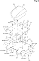
- the hinge 53 has, as depicted in FIG. 8 and FIG. 9 , fixed hinge tabs 54 provided on the base stay 46, movable hinge tabs 55 provided on the mounting stay 47, and a pivotal shaft 56 pivotally coupling the movable hinge tabs 55 to the fixed hinge tabs 54.
- the fixed hinge tabs 54 include a first hinge tab 54L and a second hinge tab 54R.
- the base stay 46 is provided at a left front end portion thereof with a first extended portion 57.
- the first extended portion 57 is formed to extend forward from the base stay 46 and then extend downward.
- the first hinge tab 54L extends rearward from a right portion of the first extended portion 57.
- the base stay 47 is provided at a right front end portion thereof with a second extended portion 58.
- the second extended portion 58 is formed to extend forward from the base stay 46 and then extend downward.
- the second hinge tab 54R extends rearward from a left portion of the second extended portion 58.
- the first hinge tab 54L and the second hinge tab 54R are opposed and spaced from each other in the vehicle width direction B3.
- the movable hinge tab 55 include a third hinge tab 55L and a fourth hinge tab 55R.
- the mounting stay 47 is provided at a central portion in the vehicle width direction B3 of a front end portion thereof with a third extended portion 59.
- the third extended portion 59 is formed to extend forward from the mounting stay 47 and then extend downward.
- the third extended portion 59 is disposed between the first extended portion 57 and the second extended portion 58.
- the third hinge tab 55L is extended rearward from a left portion of the third extended portion 59 and is opposed to the first hinge tab 54L.
- the fourth hinge tab 55R is extended rearward from a right portion of the third extended portion 59 and is opposed to the second hinge tab 54R.
- the pivotal shaft 56 comprises a first pin 56L pivotally coupling the first hinge tab 54L and the third hinge tab 55L to each other and a second pin 56R pivotally coupling the first hinge tab 54L and the third hinge tab 55L to each other.
- the first pin 56L and the second pin 56R are disposed coaxially on the axis Y2.
- the support bracket 45 has fixed tabs 60 provided on the base stay 46, movable tabs 61 provided on the mounting stay 47, and attachment screws 62 for attaching the movable tabs 61 to the fixed tabs 60 (refer to FIG. 9 ).
- the fixed tabs 60 include a first tab 60L provided on a front left end portion of the base stay 46 and a second tab 60R provided on a front right end portion of the base stay 46.
- the first tab 60L extends rearward from a left portion of the first extended portion 57.
- the second tab 60R extends rearward from a right portion of the second extended portion 58.
- the movable tabs 61 include a third tab 61L provided on a front left end portion of the mounting stay 47 and a fourth tab 61R provided on a front right end portion of the mounting stay 47.
- the third tab 61L extends leftward from the mounting stay 47 and then extends downwardly forward slantwise.
- the third tab 61L is disposed outward in the vehicle width direction of the first tab 60L.
- the fourth tab 61R extends leftward from the mounting stay 47 and then extends downwardly forward slantwise.
- the fourth tab 61R is disposed outward in the vehicle width direction of the second tab 60R.
- the attachment screws 62 include a first screw 62L which fixes the third tab 61L to the first tab 60L and a second screw 62R which fixes the fourth tab 61R to the second tab 60R.
- the attachment screws 62 (that is the first screw 62L and the second screw 62R) are provided on the axis Y2 substantially coaxial to the pivotal shaft 56. Therefore, the mounting stay 47 can be rotated only by loosening the attachment screws 62. In other words, the mounting stay 47 can be rotated even without removing the attachment screws 62. Also, the mounting stay 47 can be fixed in any rotation position.
- a first nut 63L into which the first screw 62L is screwed is fixed on a vehicle width directional inner surface of the first tab 60L.
- a second nut member 63R into which the second screw 62R is screwed is fixed on a vehicle width directional inner surface of the second tab 60R.
- an end portion of the third extended portion 59 serves as a restricting portion 64 which is brought into contact with the base stay 46 when the positioning device 30 is in the second position X2, thereby restricting forward rotation of the mounting stay 47.
- An abutting member 65 is provided on a portion of a lower surface of the base stay 46 against which the restricting portion 64 abuts.
- the abutting member 65 is formed of an elastic plate made of rubber or the like.
- FIG. 11 and FIG. 12 depict a modification example of the one embodiment.
- This modification example has at least one detection sensor 66 which detects that the positioning device 30 is in the second position X2 and a display 67 which displays that the detection sensor 66 has detected that the positioning device 30 is in the second position X2.
- the detection sensor 66 is configured of, for example, a microswitch.
- FIG. 11 depicts an example in which the detection sensor 66 is mounted on a front portion or a rear portion of the support bracket 45.
- the detection sensor 66 has a sensor main body 66A, a lever 66C having a tip portion where a roller 66B is mounted, and a button 66D.
- a front detection sensor 66F is mounted on a sensor bracket 68 disposed forwardly downward of the hinge 53 and fixed to the first bar 39.
- the third extended portion 59 abuts on the roller 66B to push and move the roller 66B, thereby causing the lever 66C to swing and push the button 66D. Therefore, it is detected that the positioning device 30 is in the second position X2.
- a rear detection sensor 66R is mounted on a sensor bracket 69 disposed rearward of the second bar 40 and downward of the base stay 46 and fixed to the second bar 40.
- the base stay 46 is formed with an opening hole 70 through which the roller 66B protrudes upward from the base stay 46.
- the mounting stay 47 pressurizes the roller 66B and the lever 66C pressurizes the button 66D.
- the mounting stay 47 placed on the base stay 46 rotates upward and then rotates forward to shift the positioning device 30 from the first position X1 to the second position X2
- the mounting stay 47 goes away from the roller 66B, and the lever 66C ceases pressurization of the button 66D. Therefore, it is detected that the positioning device 30 is in the second position X2.
- the at least one detection sensor 66 may be provided as a plurality of detection sensors.
- the mounting location where the detection sensor 66 is mounted is not limited to the location depicted in FIG. 11 .
- the detection sensor 66 may directly detect the positioning device 30 to determine whether it is in the second position X2.
- the detection sensor 66 may be a contact-type detection sensor other than a microswitch.
- the detection sensor 66 may be a non-contact-type detection sensor (a proximity sensor) configured to detect whether the positioning device 30 is in the second position X2 without making contact with the mounting stay 47, the positioning device 30, or the like.
- the detection sensor 66 is connected to the controller 26.
- the controller 26 can acquire detection information regarding statuses detected by the detection sensor 66.
- the display 67 is also connected to the controller 26.
- the display 67 is disposed near the operator's seat 10 so as to be visually recognized by the operator with ease.
- the display 67 has a screen configured as a liquid-crystal screen or the like, and it can be displayed on the screen that that the detection sensor 66 has detected the second position X2 of the positioning device 30. Therefore, the operator can recognize that automatic steering control cannot be performed with the positioning device 30 disposed in the second position X2. Note that the operator may be notified by a buzzer, voice, or the like that the positioning device 30 is in the second position X2.
- FIG. 13 and FIG. 14 depict alternative embodiments.
- the controller 26 has a restraining section 71.
- the restraining section 71 restrains automatic steering control based on detection information of the detection sensor 66. That is, the restraining section 71 does not start automatic steering control when the detection sensor 66 detects the positioning device 30 in the second position X2.
- the display 67 displays that the restraining section 71 restrains automatic steering control.
- the material for forming the mounting stay 47 and its shape may not be identical to those of the foregoing embodiment.
- the mounting stay 47 may not be necessarily configured of a member which reflects a satellite signal.
- the mounting stay 47 may not be wide in the vehicle width direction B3. That is, it may be narrow.
- the positioning device 30 has the inertial measurement unit (IMU) 33.
- IMU inertial measurement unit
- the inertial measurement unit 33 has an acceleration sensor which detects acceleration of gravity, a gyro sensor which detects an angular velocity, and so forth. By the inertial measurement unit 33, it is possible to detect a roll angle, a pitch angle, a yaw angle, and so forth of the vehicle body 5.
- the controller 26 can acquire detection information regarding statuses detected by the inertial measurement unit 33.
- the inertial measurement unit 33 an acceleration sensor, a gyro sensor, and so forth
- the inertial measurement unit 33 is a tilt sensor configured to detect the tilt of the positioning device 30. Therefore, the inertial measurement unit 33 detects a tilt of the positioning device 30 disposed in the second position X2, thereby enabling detection that the positioning device 30 is in the second position X2.
- the positioning device 30 is connected to the controller 26 and can obtain detection information from the inertial measurement unit 33.
- the controller 26 is configured to grasp that the positioning device 30 is in the second position X2 (where the positioning device 30 faces downward).
- the controller 26 has a determination section 72 and the restraining section 71.
- the determination section 72 determines, based on the detection information of the inertial measurement unit 33, whether the positioning device 30 is in the second position X2.
- the restraining section 71 restrains automatic steering control when the determination section 72 determines that the positioning device 30 is the second position X2.
- the display 67 displays that the restraining section 71 restrains automatic steering control.
- the inertial measurement unit 33 included in the positioning device 30 To detect that the positioning device 30 is in the second position X2, by using the inertial measurement unit 33 included in the positioning device 30, it is possible to simplify the structure and reduce cost.
- the working vehicle 1 of the present embodiment comprises the travelable vehicle body 5, a positioning device 30 to detect a position of the vehicle body 5 based on a signal transmitted from a positioning satellite, a controller 26 to perform automatic steering control in which steering of the vehicle body 5 is automatically controlled based on detection information detected by the positioning device 30, and the restraining section 47 or 71 to restrain automatic steering control.
- the positioning device 30 is configured to be shifted to the first position X1, which is a position for use thereof, and the second position X2, which is a position lower than the first position X1.
- the restraining section 47 or 71 restrains the automatic steering control when the positioning device 30 is in the second position.
- the automatic steering control is prevented from being performed with the positioning device 30 when in the second position X2.
- the support bracket 45 supports the positioning device 30 so as to allow the positioning device 30 to be shifted between the first position X1 and the second position X2.
- the support bracket 45 comprises the pivotal shaft 56 and the mounting stay 47 rotatable around the pivotal shaft 56 and configured so that a side of the positioning device 30 arranged as the lower surface 30b thereof when in the first position X1 is attached on the mounting stay 30.
- the mounting stay 47 rotated around the pivotal shaft 56, the positioning device 30 is shifted from the first position X1 to the second position X2 where the side of the positioning device 30 having been arranged as the upper surface 30a of the positioning device 30 when in the first position X1 comes to face downward.
- the mounting stay 47 is a member which reflects the signal transmitted from the positioning satellite and serves as the restraining section which covers over the positioning device 30 when in the second position X2 to restrain automatic steering control.
- the automatic steering control is prevented from being performed with the positioning device 30 disposed in the second position X2.
- the mounting stay 47 comprises the main plate portion 51 on which the positioning device 30 is mounted, the first extending plate portion 52L extending in one lateral direction from the main plate portion 51, and the second extending plate portion 52R extending in the other lateral direction from the main plate portion 51.
- the satellite signal can be desirably interrupted when the positioning device 30 is in the second position X2.
- the detection sensor 66 is provided to detect that the positioning device 30 is in the second position X2.
- the operator can be notified that the positioning device 30 is in the second position X2.
- the display 67 is provided to display that the detection sensor 66 has detected the second position X2.
- the operator can recognize that the positioning device 30 is in the second position X2.
- the detection sensor 66 is provided to detect that the positioning device 30 is in the second position X2, and the controller 26 has the restraining section 71 which restrains automatic steering control based on the detection information from the detection sensor 66.
- the positioning device 30 has a tilt sensor (inertial measurement unit 33) configured to detect a tile of the positioning device 30, the controller 26 has the determination section 72 which determines, based on the detection information from the tilt sensor 33, that the positioning device 30 is in the second position X2 and the restraining section 71 which restrains automatic steering control when the determination section 72 determines that the positioning device 30 is in the second position X2.
- the controller 26 has the determination section 72 which determines, based on the detection information from the tilt sensor 33, that the positioning device 30 is in the second position X2 and the restraining section 71 which restrains automatic steering control when the determination section 72 determines that the positioning device 30 is in the second position X2.
- the positioning device 30 has the inertial measurement unit 33, and the tilt sensor serves as the inertial measurement unit 33.
- the inertial measurement unit 33 included in the positioning device 30 detects that the positioning device 30 is in the second position X2, thereby simplifying the structure.
- the display 67 is provided to display that the restraining section 71 restrains automatic steering control.
- the operator can recognize that automatic steering control is not performed.
- the working vehicle 1 comprises the vehicle body 5, the positioning device 30 to detect a position of the vehicle body 5 based on a signal transmitted from a positioning satellite, and the support bracket 45 supporting the positioning device 30 so that the positioning device 30 is shiftable to the first position X1, which is a position for use thereof, and the second position X2, which is a position lower than the first position X1.
- the support bracket 45 comprises the base stay 46 mounted on a vehicle body 5 and the mounting stay 47 pivotally supported by the base stay 46 via the pivotal shaft 56 and on which the side of the positioning device 30 arranged as the lower surface 30b of the positioning device 30 when in the first position X1 is mounted.
- the positioning device 30 With the mounting stay 47 rotating around the pivotal shaft 56, the positioning device 30 is shifted from the first position X1 to the second position X2 where the side of the positioning device 30 having been arranged as the upper surface 30a of the positioning device 30 when in the first position X1 is turned to face downward.
- the positioning device 30 by moving the positioning device 30 when unused to the second position X2 lower than the first position X1, which is a position for use of the positioning device 30, the positioning device 30 is prevented from hitting an obstacle. Also, when the positioning device 30 is in the second position X2, the side of the positioning device 30 having been arranged as the upper surface 30a of the positioning device 30 when in the first position X1 comes to face downward, it is possible to set the second position X2 at a position sufficiently lower than the first position X1.
- the mounting stay 47 is placed on the base stay 46 with the positioning device 30 disposed in the first position X1.
- the positioning device 30 can be securely supported.
- the support bracket 45 has the fixed hinge tabs 54 provided to the base stay 46 and the movable-side hinge tabs 55 provided to the mounting stay 47 and pivotally supported and coupled to the fixed hinge tabs 54 via the pivotal shaft 56.
- the positioning device 30 can be shifted from the first position X1 to the second position X2 where the side of the positioning device 30 having arranged as the upper surface thereof comes to face downward.
- the support bracket 45 has the fixed tabs 60 provided on the base stay 46, the movable tabs 61 provided on the mounting stay 47, and the attachment screws 62 for attaching the movable tabs 61 to the fixed tabs 60.
- the attachment screws 62 are provided on the axis Y2 substantially coaxial to the pivotal shaft 56.
- the mounting stay 47 can be rotated by loosening the attachment screws 62.
- the cabin 9 may be mounted on the vehicle body 5, the cabin 9 may have a roof 16 at an upper portion thereof, and the positioning device 30, when in the first position X1, may be disposed above the roof 16, and, when in the second position X1, may be at least partially in a position higher than the upper end of the roof 16.
- first bar 39 and the second bar 40 extend in the vehicle width direction B3 above the roof and are juxtaposed in the fore-and-aft direction A3.
- the base stay 46 comprises the base plate portion 48 provided on the first bar 39 and the second bar 40 on which the mounting stay 47 is placed when the positioning device 30 is in the first position X1 and the extending portion 49 extending downward from the base plate portion 48 and between the first bar 39 and the second bar 40.
- the base stay 46 can be firmly mounted on the first bar 39 and the second bar 40.
Landscapes
- Engineering & Computer Science (AREA)
- Mechanical Engineering (AREA)
- Life Sciences & Earth Sciences (AREA)
- Remote Sensing (AREA)
- Radar, Positioning & Navigation (AREA)
- Soil Sciences (AREA)
- Environmental Sciences (AREA)
- Computer Networks & Wireless Communication (AREA)
- Physics & Mathematics (AREA)
- General Physics & Mathematics (AREA)
- Position Fixing By Use Of Radio Waves (AREA)
- Guiding Agricultural Machines (AREA)
- Fittings On The Vehicle Exterior For Carrying Loads, And Devices For Holding Or Mounting Articles (AREA)
- Body Structure For Vehicles (AREA)
Abstract
Description
- Conventionally, the working vehicle disclosed in
JP 2018-114925 JP 2018-114925 - For example, when the working vehicle is stored in a barn, there is a possibility that the positioning device may hit the ceiling of the barn. Moreover, when the working vehicle is transported as being placed on a truck, there is a possibility that the positioning device may hit the ceiling of a loading platform of the truck.
- In view of the above-described problem, an object of the present invention is to provide a working vehicle capable of preventing the positioning device when unused from hitting an obstacle.
- A working vehicle according to one aspect of the present invention comprises a vehicle body, a cabin mounted on the vehicle body, a bar extending along a vehicle-width direction above a roof of the cabin, a positioning device to detect a position of the vehicle body based on a signal transmitted from a positioning satellite, and a support bracket supporting the positioning device so that the positioning device supported by the support bracket is shiftable between a first position where the positioning device is used and a second position lower than the first position, wherein the support bracket comprises a base stay made of a plate having a plate surface that faces upward or downward and is fixed to the bar, and a mounting stay which is pivotally supported at a front portion thereof by the base stay via a pivotal shaft having an axis extending along the vehicle width direction and on which a lower surface of the positioning device when in the first position is attached. The mounting stay comprises a counter surface that opposes an upper surface of the base stay when the positioning device is in the first position. The positioning device is configured to be shifted from the first position to the second position according to rotation of the mounting stay around the pivotal shaft causing the counter surface to face upward so that an upper surface of the positioning device when in the first position is turned to face downward when in the second position. The mounting stay is configured so that, when the positioning device is in the second position, a front portion of the mounting stay is higher than an upper end of the roof, and a rear portion of the mounting stay is lower than the upper end of the roof.
- Also, the mounting stay may formed of a plate having a plate surface that faces upward or downward, and is placed on the base stay when the positioning device is in the first position.
- Also, the support bracket comprises a fixed hinge tab included in the base stay, and a movable hinge tab included in the mounting stay and pivotally connected to the fixed hinge tab via the pivotal shaft.
- Also, the support bracket may comprise a fixed tab included in the base stay, a movable tab included in the mounting stay, and an attachment screw attaching the movable tab to the fixed tab. The attachment screw is substantially coaxial to the pivotal shaft.
- Also, a plurality of the bars may comprise a first bar and a second bar juxtaposed in a fore-and-aft direction, and the base stay is fixed on the first bar and the second bar.
- A working vehicle according to another aspect of the present invention comprises a vehicle body, a cabin mounted on the vehicle body and including a roof at an upper portion thereof, a positioning device to detect a position of the vehicle body based on a signal transmitted from a positioning satellite, a support bracket supporting the positioning device so that the positioning device supported by the support bracket is shiftable between a first position where the positioning device is used and a second position lower than the first position, and a first bar and a second bar extending along a vehicle width direction above the roof, and juxtaposed in a fore-and-aft direction, wherein the support bracket comprises a base stay attached to the vehicle body, and a mounting stay pivotally supported by the base stay via a pivotal shaft and configured so that a lower surface of the positioning device when in the first position is attached to the mounting stay. The positioning device is configured to be shifted from the first position to the second position according to rotation of the mounting stay around the pivotal shaft so that an upper surface of the positioning device when in the first position is turned to face downward when in the second position. The base stay comprises a base plate portion provided on the first bar and the second bar and configured so that, when the positioning device is in the first position, the mounting stay is placed and attached onto the base plate portion, and an extending portion extending downward from the base plate portion and between the first bar and the second bar.
- According to the above-described working vehicle, with the positioning device moved to the second position lower than the first position, which is a position for use, it is possible to prevent the positioning device from hitting an obstacle. Also, in the second position, with the upper surface side of the positioning device in the first position facing downward, the second position can be set at a position sufficiently lower than the first position.
-
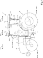
- FIG. 1
- is a side view of a working vehicle.
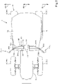
- FIG. 2
- is a plan view of the working vehicle.
- FIG. 3
- is a structural diagram depicting a partial structure and a control-system block diagram of the working vehicle.
- FIG. 4
- is a front view of an upper portion side of a cabin.
- FIG. 5
- is a perspective view of the cabin viewed from a front side.
- FIG. 6
- is a side view of an upper portion of the cabin.
- FIG. 7
- is a side view of an upper portion of a front portion of the cabin.
- FIG. 8
- is an exploded perspective view of a support bracket.
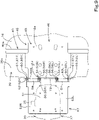
- FIG. 9
- is a plan view with the positioning device being in a second position.
- FIG. 10
- is a side sectional view with the positioning device being in the second position.
- FIG. 11
- is a side sectional view of a support bracket attachment portion according to a modification example.
- FIG. 12
- is a structural diagram depicting a partial structure and a control-system block diagram of a working vehicle according to the modification example.
- FIG. 13
- is a structural diagram depicting a partial structure and a control-system block diagram of a working vehicle according to another embodiment.
- FIG. 14
- is a structural diagram depicting a partial structure and a control-system block diagram of a working vehicle according to still another embodiment.
- In the following, one embodiment of the present invention is described with reference to the drawings as appropriate.
-
FIG. 1 is a schematic side view depicting an entire structure of aworking vehicle 1 according to one embodiment of the present invention.FIG. 2 is a schematic plan view of theworking vehicle 1. In the present embodiment, a tractor is exemplarily described as theworking vehicle 1. However, the workingvehicle 1 is not limited to a tractor but may be agricultural machine (agricultural vehicle) such as a combine or transplanter or may be construction machine (construction vehicle) or the like such as a loader working machine. - In the present embodiment, description is made by taking an arrow A1 direction (forward traveling direction of the tractor 1) in
FIG. 1 andFIG. 2 as forward, an arrow A2 direction (rearward traveling direction of the tractor 1) inFIG. 1 andFIG. 2 as rearward, and an arrow A3 direction inFIG. 1 andFIG. 2 as a fore-and-aft direction. Therefore, a front surface side ofFIG. 1 is leftward (arrow B1 direction inFIG. 2 ), and a back surface side ofFIG. 1 (arrow B2 direction inFIG. 2 ) is rightward. Also, description is made by taking a horizontal direction orthogonal to the fore-and-aft direction A3 as a vehicle width direction (arrow B3 direction inFIG. 2 ), which is a width direction of a tractor 1 (working vehicle). Description is made by taking a direction from a central portion to a right portion of thetractor 1 in the vehicle width direction B3 or a direction to a left portion thereof as outward in the vehicle width direction. In other words, outward in the vehicle width direction is the vehicle width direction B3 away from the center of thetractor 1 in the width direction. Description is made by taking a direction opposite to outward in the vehicle width direction as inward in the vehicle width direction. In other words, inward in the vehicle width direction is the vehicle width direction B3 approaching the center of thetractor 1 in the width direction. - As depicted in
FIG. 1 , thetractor 1 comprises avehicle body 5. Thevehicle body 5 comprises aprime mover 6 and apower transmission case 7. Theprime mover 6 is a diesel engine. Theprime mover 6 may be a gasoline engine or an electric motor, or may be of a hybrid system having an engine and an electric motor. Theprime mover 6 is disposed at a front portion of thetractor 1 and covered with ahood 8. - The
power transmission case 7 is configured of a plurality ofcases 7A to 7D sequentially coupled to each other in the fore-and-aft direction A3. Theforemost case 7A is coupled to a rear portion of theprime mover 6. Provided inside thepower transmission case 7 are a traveling-system power transmission mechanism which transmits power of the prime mover E1 to a travelingdevice 4 and a working-system power transmission mechanism which transmits power of the prime mover E1 to a power takeoff shaft (PTO shaft) 17. - As depicted in
FIG. 1 andFIG. 2 , thevehicle body 5 is capable of traveling. In detail, thevehicle body 5 is supported by, for example, a wheel-type traveling device 4 including a plurality of wheels enabling travel of thevehicle body 5. The plurality of wheels include paired front wheels 2 (2L, 2R) provided leftward and rightward of a front portion of thevehicle body 5 and paired rear wheels 3 (3L, 3R) provided leftward and rightward of a rear portion of thevehicle body 5. - As depicted in
FIG. 1 , thetractor 1 has acabin 9. Thecabin 9 is mounted on a rear portion of thevehicle body 5. In a rear portion of the interior of thecabin 9, an operator'sseat 10 on which an operator (operator) sits is provided. Asteering wheel 11 for steering the front wheels 2 (2L, 2R) is provided forward of the operator'sseat 10. A brake pedal (brake operation tool) 12 for performing operation for braking the travelingdevice 4 is provided downwardly rightward of thesteering wheel 11. A front surface of thecabin 9 is provided with a front glass. A back surface of thecabin 9 is provided with a rear glass. On each of side surfaces (left side surface and right side surface) of thecabin 9, anentrance 13 through which the operator gets on and off thecabin 5 and anentrance door 14 which opens and closes theentrance 13 are provided. Arear side glass 15 is provided rearward of the loading/unloadingdoor 14. Also, an upper portion of thecabin 9 is provided with aroof 16 serving as a ceiling portion thereof. - Here, with reference to
FIG. 3 , description is made on a schematic structure of a traveling system and a schematic structure of a control system of thetractor 1. - As depicted in
FIG. 3 , thetractor 1 comprises asteering device 18. Thesteering device 18 is a device operable for manual steering of thevehicle body 5 with operation by the operator and automatic steering of thevehicle body 5 without operation by the operator. Thesteering device 18 has thesteering wheel 11 and a rotation shaft 19 (steering shaft) which rotates with rotation of thesteering wheel 11. Also, thesteering device 18 has an assist mechanism (power steering mechanism) 20 which assists steering of thesteering wheel 11. In detail, theassist mechanism 20 comprises ahydraulic pump 21, acontrol valve 22 supplied with a hydraulic fluid delivered from thehydraulic pump 21, and asteering cylinder 23 controlled by thecontrol valve 22. Thecontrol valve 22 is a three-position changeover valve that is switchable with the movement of a spool or the like, and is switched in accordance with the steering direction (rotating direction) of therotation shaft 19. Also, thecontrol valve 22 is a solenoid valve controlled based on a control signal. Thesteering cylinder 23 is connected to arms (knuckle arms) 24 for steering of thefront wheels 2. - When the operator holds and operates the
steering wheel 11 in one direction or another direction, the position and the opening degree of thecontrol valve 22 are switched in accordance with the rotating direction of thesteering wheel 11 and, a piston rod of thesteering cylinder 23 moves leftward or rightward in accordance with the position and the opening degree of thecontrol valve 22, thereby steering thefront wheels 2. That is, thevehicle body 5 can change the forwarding direction to left or right by manual steering of thesteering wheel 11. Note that the above-describedsteering device 18 is one example and is not limited to have the above-described structure. - As depicted in
FIG. 3 , thetractor 1 comprises acontroller 26. Thecontroller 26 comprises a microprocessor having a CPU (Central Processing Unit), an EEPROM (Electrically Erasable Programmable Read-Only Memory), and so forth. - The
controller 26 performs various controls for thetractor 1. To thecontroller 26, astate detection device 27 which detects a driving state and so forth of thetractor 1 is connected. Thestate detection device 27 is, for example, a device which detects a state of the traveling system, and detects the states of, for example, a crank sensor, a cam sensor, an engine rotation sensor, an accelerator sensor, a vehicle-speed sensor, a steering-angle sensor, a later-discussedpositioning device 30, and/or so forth. Alternatively, thestate detection device 27 may be a lifting lever detection sensor, a PTO rotation detection sensor, or the like, other than a sensor for detecting the state of the traveling system. Thecontroller 26 performs control of the traveling system and control of the working system in thetractor 1. Thecontroller 26 controls, for example, the number of revolutions of the prime mover 6 (engine), the steering angle of thesteering device 18, and so forth based on the detection state detected by thestate detection device 27. Also, thestate detection device 27 performs control of lifting of the lifting device which lifts the working machine attached to thetractor 1, the number of PTO rotations, and so forth based on the state detected by thestate detection device 27. - Connected to the
controller 26 is thepositioning device 30 which detects the position of the vehicle body 5 (tractor 1) based on a signal (satellite signal) transmitted from a positioning satellite. Thecontroller 26 is configured or programmed to acquire detection information (position) detected by thepositioning device 30. The positioning device is a device which detects its own position (positioning information including a latitude and a longitude) by the satellite positioning system (positioning satellite). That is, thepositioning device 30 receives a satellite signal (position of the positioning satellite, transmission time, correction information, and so forth), which is a signal transmitted from the positioning satellite, and detects the position (for example, latitude and longitude) based on the satellite signal. - Also, the
positioning device 30 detects the position and azimuth of thevehicle body 5 by using a known GPS (Global Positioning System), which is one example of a global navigation satellite system (GNSS). Note thatpositioning device 30 may be a satellite positioning system such as GLONASS, HOKUTO, GALILEO, or MICHIBIKI. - As depicted in
FIG. 3 , thepositioning device 30 has, for example, areceiver 31 and awireless transceiver 32. - The
receiver 31 has an antenna and so forth, and receives a satellite signal transmitted from a positioning satellite. - The
wireless transceiver 32 has an antenna and so forth, and communicates with a base station (reference station) installed at a known position. The base station transmits positioning data (correction information) acquired by receiving electric waves from the positioning satellite to thepositioning device 30. Thepositioning device 30 receives electric waves transmitted from the positioning satellite and positioning data transmitted from the base station, and detects its own position (latitude and longitude) based on positioning data acquired by receiving the electric waves from the positioning satellite and the positioning data from the base station. - Note that the
positioning device 30 may not necessarily include thewireless transceiver 32. Also, thepositioning device 30 may not include aninertial measurement unit 33, which will be described further below. - The
controller 26 performs automatic steering control of automatically controlling steering of thevehicle body 5 based on the detection information detected by thepositioning device 30. - To perform automatic steering control, first, a traveling reference line is determined, and then, a planned traveling line parallel to the traveling reference line is determined, thereby allowing the automatic steering control to be performed.
- In automatic steering control, steering of the tractor 1 (vehicle body 5) is automatically performed so that the vehicle-body position is measured by the
positioning device 30 and the planned traveling line. Specifically, before automatic steering control is performed, the tractor 1 (vehicle body 5) is moved to a predetermined position in an agricultural field, and when thetractor 1 arrives at the predetermined position, the operator operates a steering changeover switch (registration switch) provided in thetractor 1 so as to determine the vehicle-body position measured by thepositioning device 30 as a start point of the traveling reference line. Also, the tractor 1 (vehicle body 5) is moved from the start point of the traveling reference line, and when thetractor 1 arrives at another predetermined position, the operator operates the steering changeover switch so as to determine the vehicle-body position measured by thepositioning device 30 as an end point of the traveling reference line. A straight line connecting the start point and the end point is set as a traveling reference line. - After the traveling reference line is set, for example, the tractor 1 (vehicle body 5) is moved to a location different from the location where the traveling reference line is set and the operator operates the steering changeover switch so as to set a planned traveling line, which is a straight line parallel to the traveling reference line. After the planned traveling line is set, the automatic steering control starts so that the tractor 1 (vehicle body 5) is steered to travel along the planned traveling line.
- As depicted in
FIG. 4 andFIG. 5 , thecabin 9 hasfront pillars 36 at a front portion thereof. Thefront pillars 36 comprises a firstfront pillar 36L positioned on one side in the vehicle width direction B3 (left side) of the front portion of thecabin 9 and a secondfront pillar 36R positioned on the other side in the vehicle width direction B3 (right side) of the front portion of thecabin 9. The front glass is provided between the firstfront pillar 36L and the secondfront pillar 36R. Upper portions of the firstfront pillar 36L and the secondfront pillar 36R are coupled to each other by a frontupper frame 37. - As depicted in
FIG. 4 andFIG. 5 , thepositioning device 30 is mounted on asupport frame 38 interposed between the upper portion of the firstfront pillar 36L and the upper portion of the secondfront pillar 36R. Thepositioning device 30 comprises acase 34 that accommodates thereceiver 31, thewireless transceiver 32, and so forth, and is configured to receive a satellite signal transmitted from the positioning satellite and detect a position thereof based on the received satellite signal. On a right side of thepositioning device 30, a connectingportion 35 for connecting a connection terminal of a harness is provided (refer toFIG. 9 ). - As depicted in
FIG. 4 andFIG. 5 , thesupport frame 38 has afirst bar 39 and asecond bar 40 provided to extend in the vehicle width direction B3, afirst frame stay 41L provided on one end side in the vehicle width direction B3 (left end side) of thefirst bar 39 and thesecond bar 40, and asecond frame stay 41R provided on the other end side (right end side) in the vehicle width direction B3 of thefirst bar 39 and thesecond bar 40. Thefirst bar 39 and thesecond bar 40 are each formed of, for example, a rod-shaped member such as a pipe member, and are juxtaposed in the fore-and-aft direction A3 above theroof 16. - As depicted in
FIG. 2 andFIG. 5 , thefirst bar 39 has a firstlinear bar portion 39a, a firstvertical bar portion 39b, and a secondvertical bar portion 39c. The firstlinear bar portion 39a is disposed above a front portion of theroof 16. In detail, the firstlinear bar portion 39a linearly extends in the vehicle-width direction B3 between the firstfront pillar 36L and the secondfront pillar 36R. The firstvertical bar portion 39b is extended downward from a left end of the firstlinear bar portion 39a. The secondvertical bar portion 39c is extended downward from a right end of the firstlinear bar portion 39a. - As depicted in
FIG. 2 andFIG. 5 , thesecond bar 40 has a secondlinear bar portion 40a, a first tiltedportion 40b, a second tiltedportion 40c, a thirdvertical bar portion 40d, and a fourthvertical bar portion 40e. The secondlinear bar portion 40a is disposed above theroof 16 and below the firstlinear bar portion 39a. Also, the secondlinear bar portion 40a is spaced from the firstlinear bar portion 39a and substantially parallel to the firstlinear bar portion 39a. The first tiltedportion 40b extends forwardly leftward slantwise from one end (left end) of the firstlinear bar portion 39a. A left end of the first tiltedportion 40b is disposed rearward of a left end of the firstlinear bar portion 39a. The second tiltedportion 40c extends forwardly rightward slantwise from the other end (right end) of the secondlinear bar portion 40a. A right end of the second tiltedportion 40c is disposed rearward of a right end of the firstlinear bar portion 39a. The thirdvertical bar portion 40d is extended downward from a left end of the first tiltedportion 40b. The fourthvertical bar portion 40e is extended downward from a right end of the secondtiled portion 40c. - As depicted in
FIG. 4 andFIG. 5 , the first frame stay 41L and the second frame stay 41R are each formed of a plate-shaped member. The first frame stay 41L has an upper portion interposed between the firstvertical bar portion 39b and the thirdvertical bar portion 40d and fixed to the firstvertical bar portion 39b and the thirdvertical bar portion 40d. The second frame stay 41R has an upper portion interposed between the secondvertical bar portion 39c and the fourthvertical bar portion 40e and fixed to the secondvertical bar portion 39c and the secondvertical bar portion 40e. - As depicted in
FIG. 4 , thesupport frame 38 is mounted at one end thereof on an upper portion of the firstfront pillar 36L, and at the other end thereof on an upper portion of the secondfront pillar 36R. In detailed description, afirst mounting tab 42L is fixed to the upper portion of the firstfront pillar 36L, and asecond mounting tab 42R is fixed to the upper portion of the secondfront pillar 36R. Thefirst mounting tab 42L and thesecond mounting tab 42R are each formed of a plate. Thefirst mounting tab 42L protrudes leftward forward from a front portion of the firstfront pillar 36L. Thesecond mounting tab 42R protrudes rightward forward from a front portion of the secondfront pillar 36R. The first frame stay 41L is mounted on thefirst mounting tab 42L with a bolt and a nut, and the second frame stay 41R is mounted on thesecond mounting tab 42R with a bolt and a nut. - As depicted in
FIG. 4 andFIG. 5 , afirst side mirror 43L is disposed on a left lateral side of the upper portion of the firstfront pillar 36L, and asecond side mirror 43R is disposed on a right lateral side of the upper portion of the secondfront pillar 36R. Thefirst side mirror 43L and thesecond side mirror 43R are mirrors for visually recognizing rearward and rearward sideward of thevehicle body 5. Thefirst side mirror 43L and thesecond side mirror 43R each has a mirrormain body 43a, abracket arm 43b for supporting the mirrormain body 43a, and a mountingpart 43c for supporting thebracket arm 43b rotatable about a vertical axis. The mountingpart 43c of thefirst side mirror 43L is fixed to thefirst mounting tab 42L. The mountingpart 43c of thesecond side mirror 43R is fixed to thesecond mounting tab 42R. Also, aradio antenna 44 is mounted on thesecond mounting tab 42R. - As depicted in
FIG. 2 ,FIG. 4 , andFIG. 5 , thesupport frame 38 has asupport bracket 45 for supporting thepositioning device 30. Thesupport bracket 45 is provided at a substantially central portion in the vehicle width direction B3 between thefirst bar 39 and thesecond bar 40. - As depicted in
FIG. 6 to FIG. 10 , thesupport bracket 45 has abase stay 46 to be mounted on avehicle body 5 side and a mountingstay 47 pivotally supported and coupled to thebase stay 46. Thebase stay 46 and the mountingstay 47 are each formed of a plate. - As depicted in
FIG. 8 andFIG. 9 , thebase stay 46 has abase plate portion 48 provided on thefirst bar 39 and thesecond bar 40 and an extendingportion 49 extending downward from thebase plate portion 48 and between thefirst bar 39 and thesecond bar 40. Amain body portion 48a of thebase plate portion 48 is formed in a rectangular shape in plain view, and is fixed to thefirst bar 39 and thesecond bar 40. A rear portion of thebase plate portion 48 is bent downward. In detail, thebase plate portion 48 has awall portion 48b extending downward from a rear end of themain body portion 48a. The extendingportion 49 comprises a first extendingwall 49L extending downward from an intermediate portion in the fore-and-aft direction A3 of a left end of thebase plate portion 48 and a second extendingwall 49R extending downward from an intermediate portion in the fore-and-aft direction A3 of a right end of thebase plate portion 48. The first extendingwall 49L and the second extendingwall 49R are fixed to thefirst bar 39 and thesecond bar 40. The base stay 46 having the first extendingwall 49L and the second extendingwall 49R can be firmly mounted on thefirst bar 39 and thesecond bar 40. - As depicted in
FIG. 7 , thepositioning device 30 is mounted on the mountingstay 47 with bolts. As depicted inFIG. 6 , the mountingstay 47 is pivotally supported by a front portion of the base stay 46 rotatable about an axis extending in the vehicle width direction B3 so that, by rotating the mountingstay 47, thepositioning device 30 is shifted to a first position X1, which is a position for use of thepositioning device 30, and a second position X2, which is a position lower than the first position. That is, thesupport bracket 45 supports thepositioning device 30 so as to enable thepositioning device 30 to move to the first position X1 and the second position X2. Also, by rotating the mountingstay 47, thepositioning device 30 flips from the first position X1 to the second position X2 and, when in the second position X2, is in a downward-facing state in which a side of thepositioning device 30 having been arranged as anupper surface 30a of thepositioning device 30 when in the first position X1 comes to face downward. Therefore, thepositioning device 30, when unused, is shifted from the first position X1 to the second position X2 so as to be prevented from hitting an obstacle. Also, only by rotating the mountingstay 47, the second position X2 can be set at a position sufficiently lower than the first position X1. - In the present embodiment, when the
positioning device 30 is in the second position X2, thepositioning device 30 is tilted upwardly forward and the side of thepositioning device 30 having arranged as theupper surface 30a faces downward. - As depicted in
FIG. 7 , when thepositioning device 30 is in the first position X1, the mountingstay 47 is disposed downward of thepositioning device 30. Therefore, a side of thepositioning device 30 arranged as alower surface 30b thereof is attached to the mountingstay 47. Also, when thepositioning device 30 is in the first position X1, the mountingstay 47 is placed on the base stay 46 (base plate portion 48). In this state, the mountingstay 47 is mounted on the base stay 46 with bolts 50 (refer toFIG. 8 ). Nuts into which thebolts 50 are screwed are fixed to a lower surface of thebase stay 46. - As depicted in
FIG. 9 , the mountingstay 47 has amain plate portion 51 on which thepositioning device 30 is mounted, a first extendingplate portion 52L extending in one lateral direction (leftward) from themain plate portion 51, and a second extendingplate portion 52R extending in the other lateral direction (rightward) from themain plate portion 51. - As depicted in
FIG. 9 andFIG. 10 , when thepositioning device 30 is in the second position X2, the mountingstay 47 covers the positioning device 30 (receiver 31, wireless transceiver 32). Also, the mountingstay 47 is a member which reflects a satellite signal. Therefore, when thepositioning device 30 is in the second position X2, thepositioning device 30 cannot effectively receive a satellite signal. That is, when thepositioning device 30 is in the second position X2, automatic steering control is restrained by the mountingstay 47. In other words, the mountingstay 47 serves as a restraining section that covers over the positioneddevice 30 in the second position X2 to restrain the automatic steering control. When thepositioning device 30 is in the second position X2, the mountingstay 47 restrains the automatic steering control, thereby preventing working with automatic control steering from being performed. - The mounting
stay 47 is formed of, for example, a metal plate such as an iron plate. - As depicted in
FIG. 6 , thepositioning device 30, when in the first position X2, is disposed above theroof 16, and, when in the second position X2, is mostly positioned lower than an upper end of theroof 16 and is partially higher than the upper end of theroof 16. InFIG. 6 , a one-dot-chain line indicates an extension line Y1 of an uppermost end of theroof 16. In the exemplary drawing, an upper front portion of thepositioning device 30 in the second position X2 is at a position higher than the extension line Y1. - As depicted in
FIG. 5 andFIG. 10 , thesupport frame 38 has ahinge 53 which pivotally couples the mountingstay 47 to the base stay 46 so that the mountingstay 47 is rotatable about the axis extending in the vehicle width direction B3. - The
hinge 53 has, as depicted inFIG. 8 andFIG. 9 , fixedhinge tabs 54 provided on thebase stay 46,movable hinge tabs 55 provided on the mountingstay 47, and apivotal shaft 56 pivotally coupling themovable hinge tabs 55 to the fixedhinge tabs 54. - The fixed
hinge tabs 54 include afirst hinge tab 54L and asecond hinge tab 54R. Thebase stay 46 is provided at a left front end portion thereof with a firstextended portion 57. The firstextended portion 57 is formed to extend forward from thebase stay 46 and then extend downward. Thefirst hinge tab 54L extends rearward from a right portion of the firstextended portion 57. Also, thebase stay 47 is provided at a right front end portion thereof with a secondextended portion 58. The secondextended portion 58 is formed to extend forward from thebase stay 46 and then extend downward. Thesecond hinge tab 54R extends rearward from a left portion of the secondextended portion 58. Thefirst hinge tab 54L and thesecond hinge tab 54R are opposed and spaced from each other in the vehicle width direction B3. - The
movable hinge tab 55 include athird hinge tab 55L and afourth hinge tab 55R. The mountingstay 47 is provided at a central portion in the vehicle width direction B3 of a front end portion thereof with a thirdextended portion 59. The thirdextended portion 59 is formed to extend forward from the mountingstay 47 and then extend downward. The thirdextended portion 59 is disposed between the firstextended portion 57 and the secondextended portion 58. Thethird hinge tab 55L is extended rearward from a left portion of the thirdextended portion 59 and is opposed to thefirst hinge tab 54L. Thefourth hinge tab 55R is extended rearward from a right portion of the thirdextended portion 59 and is opposed to thesecond hinge tab 54R. - As depicted in
FIG. 9 , thepivotal shaft 56 comprises a first pin 56L pivotally coupling thefirst hinge tab 54L and thethird hinge tab 55L to each other and asecond pin 56R pivotally coupling thefirst hinge tab 54L and thethird hinge tab 55L to each other. The first pin 56L and thesecond pin 56R are disposed coaxially on the axis Y2. - As depicted in
FIG. 8 , thesupport bracket 45 has fixedtabs 60 provided on thebase stay 46,movable tabs 61 provided on the mountingstay 47, and attachment screws 62 for attaching themovable tabs 61 to the fixed tabs 60 (refer toFIG. 9 ). - The fixed
tabs 60 include afirst tab 60L provided on a front left end portion of thebase stay 46 and asecond tab 60R provided on a front right end portion of thebase stay 46. Thefirst tab 60L extends rearward from a left portion of the firstextended portion 57. Thesecond tab 60R extends rearward from a right portion of the secondextended portion 58. - The
movable tabs 61 include athird tab 61L provided on a front left end portion of the mountingstay 47 and afourth tab 61R provided on a front right end portion of the mountingstay 47. Thethird tab 61L extends leftward from the mountingstay 47 and then extends downwardly forward slantwise. Thethird tab 61L is disposed outward in the vehicle width direction of thefirst tab 60L. Thefourth tab 61R extends leftward from the mountingstay 47 and then extends downwardly forward slantwise. Thefourth tab 61R is disposed outward in the vehicle width direction of thesecond tab 60R. - As depicted in
FIG. 9 , the attachment screws 62 include afirst screw 62L which fixes thethird tab 61L to thefirst tab 60L and asecond screw 62R which fixes thefourth tab 61R to thesecond tab 60R. The attachment screws 62 (that is thefirst screw 62L and thesecond screw 62R) are provided on the axis Y2 substantially coaxial to thepivotal shaft 56. Therefore, the mountingstay 47 can be rotated only by loosening the attachment screws 62. In other words, the mountingstay 47 can be rotated even without removing the attachment screws 62. Also, the mountingstay 47 can be fixed in any rotation position. - A first nut 63L into which the
first screw 62L is screwed is fixed on a vehicle width directional inner surface of thefirst tab 60L. Asecond nut member 63R into which thesecond screw 62R is screwed is fixed on a vehicle width directional inner surface of thesecond tab 60R. - As depicted in
FIG. 10 , an end portion of the thirdextended portion 59 serves as a restrictingportion 64 which is brought into contact with thebase stay 46 when thepositioning device 30 is in the second position X2, thereby restricting forward rotation of the mountingstay 47. An abuttingmember 65 is provided on a portion of a lower surface of the base stay 46 against which the restrictingportion 64 abuts. The abuttingmember 65 is formed of an elastic plate made of rubber or the like. When the restrictingportion 64 is brought into contact with thebase stay 46, the elastic plate serving as the abuttingmember 65 provided on the base stay 46 directly abuts against the restrictingportion 64, thereby absorbing shock generated by the contact between the restrictingportion 64 and thebase stay 46. -
FIG. 11 andFIG. 12 depict a modification example of the one embodiment. This modification example has at least onedetection sensor 66 which detects that thepositioning device 30 is in the second position X2 and adisplay 67 which displays that thedetection sensor 66 has detected that thepositioning device 30 is in the second position X2. - As depicted in
FIG. 11 , thedetection sensor 66 is configured of, for example, a microswitch.FIG. 11 depicts an example in which thedetection sensor 66 is mounted on a front portion or a rear portion of thesupport bracket 45. Thedetection sensor 66 has a sensormain body 66A, alever 66C having a tip portion where aroller 66B is mounted, and abutton 66D. - A
front detection sensor 66F is mounted on asensor bracket 68 disposed forwardly downward of thehinge 53 and fixed to thefirst bar 39. In thisdetection sensor 66F, when thepositioning device 30 is shifted to the second position X2, the thirdextended portion 59 abuts on theroller 66B to push and move theroller 66B, thereby causing thelever 66C to swing and push thebutton 66D. Therefore, it is detected that thepositioning device 30 is in the second position X2. - A
rear detection sensor 66R is mounted on asensor bracket 69 disposed rearward of thesecond bar 40 and downward of thebase stay 46 and fixed to thesecond bar 40. Thebase stay 46 is formed with anopening hole 70 through which theroller 66B protrudes upward from thebase stay 46. In thisdetection sensor 66R, when thepositioning device 30 is in the first position X1, the mountingstay 47 pressurizes theroller 66B and thelever 66C pressurizes thebutton 66D. When the mountingstay 47 placed on thebase stay 46 rotates upward and then rotates forward to shift thepositioning device 30 from the first position X1 to the second position X2, the mountingstay 47 goes away from theroller 66B, and thelever 66C ceases pressurization of thebutton 66D. Therefore, it is detected that thepositioning device 30 is in the second position X2. - The at least one
detection sensor 66 may be provided as a plurality of detection sensors. The mounting location where thedetection sensor 66 is mounted is not limited to the location depicted inFIG. 11 . Also, thedetection sensor 66 may directly detect thepositioning device 30 to determine whether it is in the second position X2. Also, thedetection sensor 66 may be a contact-type detection sensor other than a microswitch. Also, thedetection sensor 66 may be a non-contact-type detection sensor (a proximity sensor) configured to detect whether thepositioning device 30 is in the second position X2 without making contact with the mountingstay 47, thepositioning device 30, or the like. - As depicted in
FIG. 12 , thedetection sensor 66 is connected to thecontroller 26. Thecontroller 26 can acquire detection information regarding statuses detected by thedetection sensor 66. Thedisplay 67 is also connected to thecontroller 26. Thedisplay 67 is disposed near the operator'sseat 10 so as to be visually recognized by the operator with ease. Thedisplay 67 has a screen configured as a liquid-crystal screen or the like, and it can be displayed on the screen that that thedetection sensor 66 has detected the second position X2 of thepositioning device 30. Therefore, the operator can recognize that automatic steering control cannot be performed with thepositioning device 30 disposed in the second position X2. Note that the operator may be notified by a buzzer, voice, or the like that thepositioning device 30 is in the second position X2. - Structures other than the above-specified structures are similar to those of the foregoing embodiment.
-
FIG. 13 andFIG. 14 depict alternative embodiments. - In the alternative embodiment depicted in
FIG. 13 , thecontroller 26 has a restrainingsection 71. The restrainingsection 71 restrains automatic steering control based on detection information of thedetection sensor 66. That is, the restrainingsection 71 does not start automatic steering control when thedetection sensor 66 detects thepositioning device 30 in the second position X2. Thedisplay 67 displays that the restrainingsection 71 restrains automatic steering control. - The material for forming the mounting
stay 47 and its shape may not be identical to those of the foregoing embodiment. In this regard, if thecontroller 26 has the restrainingsection 71, the mountingstay 47 may not be necessarily configured of a member which reflects a satellite signal. Also, the mountingstay 47 may not be wide in the vehicle width direction B3. That is, it may be narrow. - Structures other than the above-specified structures are similar to those of the foregoing embodiment and modification example.
- In another embodiment depicted in
FIG. 14 , thepositioning device 30 has the inertial measurement unit (IMU) 33. - The
inertial measurement unit 33 has an acceleration sensor which detects acceleration of gravity, a gyro sensor which detects an angular velocity, and so forth. By theinertial measurement unit 33, it is possible to detect a roll angle, a pitch angle, a yaw angle, and so forth of thevehicle body 5. Thecontroller 26 can acquire detection information regarding statuses detected by theinertial measurement unit 33. - By the inertial measurement unit 33 (an acceleration sensor, a gyro sensor, and so forth), the tilt of the
positioning device 30 can be detected. That is, theinertial measurement unit 33 is a tilt sensor configured to detect the tilt of thepositioning device 30. Therefore, theinertial measurement unit 33 detects a tilt of thepositioning device 30 disposed in the second position X2, thereby enabling detection that thepositioning device 30 is in the second position X2. Thepositioning device 30 is connected to thecontroller 26 and can obtain detection information from theinertial measurement unit 33. Thus, thecontroller 26 is configured to grasp that thepositioning device 30 is in the second position X2 (where thepositioning device 30 faces downward). - The
controller 26 has adetermination section 72 and the restrainingsection 71. Thedetermination section 72 determines, based on the detection information of theinertial measurement unit 33, whether thepositioning device 30 is in the second position X2. The restrainingsection 71 restrains automatic steering control when thedetermination section 72 determines that thepositioning device 30 is the second position X2. Thedisplay 67 displays that the restrainingsection 71 restrains automatic steering control. - To detect that the
positioning device 30 is in the second position X2, by using theinertial measurement unit 33 included in thepositioning device 30, it is possible to simplify the structure and reduce cost. - The working
vehicle 1 of the present embodiment comprises thetravelable vehicle body 5, apositioning device 30 to detect a position of thevehicle body 5 based on a signal transmitted from a positioning satellite, acontroller 26 to perform automatic steering control in which steering of thevehicle body 5 is automatically controlled based on detection information detected by thepositioning device 30, and the restrainingsection positioning device 30 is configured to be shifted to the first position X1, which is a position for use thereof, and the second position X2, which is a position lower than the first position X1. The restrainingsection positioning device 30 is in the second position. - According to this structure, the automatic steering control is prevented from being performed with the
positioning device 30 when in the second position X2. - Also, the
support bracket 45 supports thepositioning device 30 so as to allow thepositioning device 30 to be shifted between the first position X1 and the second position X2. Thesupport bracket 45 comprises thepivotal shaft 56 and the mountingstay 47 rotatable around thepivotal shaft 56 and configured so that a side of thepositioning device 30 arranged as thelower surface 30b thereof when in the first position X1 is attached on the mountingstay 30. With the mountingstay 47 rotated around thepivotal shaft 56, thepositioning device 30 is shifted from the first position X1 to the second position X2 where the side of thepositioning device 30 having been arranged as theupper surface 30a of thepositioning device 30 when in the first position X1 comes to face downward. The mountingstay 47 is a member which reflects the signal transmitted from the positioning satellite and serves as the restraining section which covers over thepositioning device 30 when in the second position X2 to restrain automatic steering control. - According to this structure, even if it is not detected that the
positioning device 30 is in the second position X2, the automatic steering control is prevented from being performed with thepositioning device 30 disposed in the second position X2. - Also, the mounting
stay 47 comprises themain plate portion 51 on which thepositioning device 30 is mounted, the first extendingplate portion 52L extending in one lateral direction from themain plate portion 51, and the second extendingplate portion 52R extending in the other lateral direction from themain plate portion 51. - According to this structure, the satellite signal can be desirably interrupted when the
positioning device 30 is in the second position X2. - Also, the
detection sensor 66 is provided to detect that thepositioning device 30 is in the second position X2. - According to this structure, the operator can be notified that the
positioning device 30 is in the second position X2. - Also, the
display 67 is provided to display that thedetection sensor 66 has detected the second position X2. - According to this structure, the operator can recognize that the
positioning device 30 is in the second position X2. - Also, the
detection sensor 66 is provided to detect that thepositioning device 30 is in the second position X2, and thecontroller 26 has the restrainingsection 71 which restrains automatic steering control based on the detection information from thedetection sensor 66. - According to this structure, automatic steering control is prevented from being performed with the
positioning device 30 disposed in the second position X2. - Also, the
positioning device 30 has a tilt sensor (inertial measurement unit 33) configured to detect a tile of thepositioning device 30, thecontroller 26 has thedetermination section 72 which determines, based on the detection information from thetilt sensor 33, that thepositioning device 30 is in the second position X2 and the restrainingsection 71 which restrains automatic steering control when thedetermination section 72 determines that thepositioning device 30 is in the second position X2. - Also according to this structure, automatic steering control is prevented from being performed with the
positioning device 30 disposed in the second position X2. - Also, the
positioning device 30 has theinertial measurement unit 33, and the tilt sensor serves as theinertial measurement unit 33. - According to this structure, the
inertial measurement unit 33 included in thepositioning device 30 detects that thepositioning device 30 is in the second position X2, thereby simplifying the structure. - Also, the
display 67 is provided to display that the restrainingsection 71 restrains automatic steering control. - According to this structure, the operator can recognize that automatic steering control is not performed.
- Also, the working
vehicle 1 comprises thevehicle body 5, thepositioning device 30 to detect a position of thevehicle body 5 based on a signal transmitted from a positioning satellite, and thesupport bracket 45 supporting thepositioning device 30 so that thepositioning device 30 is shiftable to the first position X1, which is a position for use thereof, and the second position X2, which is a position lower than the first position X1. Thesupport bracket 45 comprises the base stay 46 mounted on avehicle body 5 and the mountingstay 47 pivotally supported by thebase stay 46 via thepivotal shaft 56 and on which the side of thepositioning device 30 arranged as thelower surface 30b of thepositioning device 30 when in the first position X1 is mounted. With the mountingstay 47 rotating around thepivotal shaft 56, thepositioning device 30 is shifted from the first position X1 to the second position X2 where the side of thepositioning device 30 having been arranged as theupper surface 30a of thepositioning device 30 when in the first position X1 is turned to face downward. - According to this structure, by moving the
positioning device 30 when unused to the second position X2 lower than the first position X1, which is a position for use of thepositioning device 30, thepositioning device 30 is prevented from hitting an obstacle. Also, when thepositioning device 30 is in the second position X2, the side of thepositioning device 30 having been arranged as theupper surface 30a of thepositioning device 30 when in the first position X1 comes to face downward, it is possible to set the second position X2 at a position sufficiently lower than the first position X1. - Also, the mounting
stay 47 is placed on the base stay 46 with thepositioning device 30 disposed in the first position X1. - According to this structure, at the time of using the
positioning device 30, thepositioning device 30 can be securely supported. - Also, the
support bracket 45 has the fixedhinge tabs 54 provided to thebase stay 46 and the movable-side hinge tabs 55 provided to the mountingstay 47 and pivotally supported and coupled to the fixedhinge tabs 54 via thepivotal shaft 56. - According to this structure, the
positioning device 30 can be shifted from the first position X1 to the second position X2 where the side of thepositioning device 30 having arranged as the upper surface thereof comes to face downward. - Also, the
support bracket 45 has the fixedtabs 60 provided on thebase stay 46, themovable tabs 61 provided on the mountingstay 47, and the attachment screws 62 for attaching themovable tabs 61 to the fixedtabs 60. The attachment screws 62 are provided on the axis Y2 substantially coaxial to thepivotal shaft 56. - According to this structure, the mounting
stay 47 can be rotated by loosening the attachment screws 62. - Also, the
cabin 9 may be mounted on thevehicle body 5, thecabin 9 may have aroof 16 at an upper portion thereof, and thepositioning device 30, when in the first position X1, may be disposed above theroof 16, and, when in the second position X1, may be at least partially in a position higher than the upper end of theroof 16. - Also, the
first bar 39 and thesecond bar 40 extend in the vehicle width direction B3 above the roof and are juxtaposed in the fore-and-aft direction A3. Thebase stay 46 comprises thebase plate portion 48 provided on thefirst bar 39 and thesecond bar 40 on which the mountingstay 47 is placed when thepositioning device 30 is in the first position X1 and the extendingportion 49 extending downward from thebase plate portion 48 and between thefirst bar 39 and thesecond bar 40. - According to this structure, the base stay 46 can be firmly mounted on the
first bar 39 and thesecond bar 40. - While one embodiment of the present invention has been described above, the embodiment disclosed herein should be construed as being an example in all aspects and not being restrictive. The scope of the present invention is indicated not by the above description but by the scope of claims, and is intended to include all modifications in the scope of claims and the meanings and scopes of equivalents.
-
- 5
- Vehicle body
- 9
- Cabin
- 16
- Roof
- 30
- Positioning device
- 30a
- Upper surface
- 30b
- Lower surface
- 39
- First bar
- 40
- Second bar
- 45
- Support bracket
- 46
- Base stay
- 47
- Mounting stay
- 48
- Base plate portion
- 49
- Extending portion
- 54
- Fixed hinge tab
- 55
- Movable hinge tab
- 56
- Pivotal shaft
- 60
- Fixed tab
- 61
- Movable tab
- 62
- Attachment screw
- A3
- Fore-and-aft direction
- B3
- Vehicle width direction
- X1
- First position
- X2
- Second position
- Y2
- Axis
Claims (6)
- A working vehicle, comprising:- a vehicle body;- a cabin mounted on the vehicle body;- a bar extending along a vehicle-width direction above a roof of the cabin;- a positioning device to detect a position of the vehicle body based on a signal transmitted from a positioning satellite; and- a support bracket supporting the positioning device so that the positioning device supported by the support bracket is shiftable between a first position where the positioning device is used and a second position lower than the first position, the support bracket comprisingwherein- a base stay made of a plate having a plate surface that faces upward or downward and is fixed to the bar, and- a mounting stay which is pivotally supported at a front portion thereof by the base stay via a pivotal shaft having an axis extending along the vehicle width direction and on which a lower surface of the positioning device when in the first position is attached, wherein the mounting stay comprises a counter surface that opposes an upper surface of the base stay when the positioning device is in the first position;- the positioning device is configured to be shifted from the first position to the second position according to rotation of the mounting stay around the pivotal shaft causing the counter surface to face upward so that an upper surface of the positioning device when in the first position is turned to face downward when in the second position, and- the mounting stay is configured so that, when the positioning device is in the second position, a front portion of the mounting stay is higher than an upper end of the roof, and a rear portion of the mounting stay is lower than the upper end of the roof.
- The working vehicle according to claim 1, wherein the mounting stay is formed of a plate having a plate surface that faces upward or downward, and is placed on the base stay when the positioning device is in the first position.
- The working vehicle according to claim 1 or 2, wherein the support bracket comprises- a fixed hinge tab included in the base stay, and- a movable hinge tab included in the mounting stay and pivotally connected to the fixed hinge tab via the pivotal shaft.
- The working vehicle according to any one of claims 1 to 3, wherein the support bracket comprises- a fixed tab included in the base stay,- a movable tab included in the mounting stay, and- an attachment screw attaching the movable tab to the fixed tab, the attachment screw being substantially coaxial to the pivotal shaft.
- The working vehicle according to claim 1 or 4, wherein a plurality of the bars comprises a first bar and a second bar juxtaposed in a fore-and-aft direction, and the base stay is fixed on the first bar and the second bar.
- A working vehicle, comprising:- a vehicle body;- a cabin mounted on the vehicle body and including a roof at an upper portion thereof;- a positioning device to detect a position of the vehicle body based on a signal transmitted from a positioning satellite;- a support bracket supporting the positioning device so that the positioning device supported by the support bracket is shiftable between a first position where the positioning device is used and a second position lower than the first position, the support bracket comprising- a base stay attached to the vehicle body, and- a mounting stay pivotally supported by the base stay via a pivotal shaft and configured so that a lower surface of the positioning device when in the first position is attached to the mounting stay; and- a first bar and a second bar extending along a vehicle width direction above the roof, and juxtaposed in a fore-and-aft direction;wherein- the positioning device is configured to be shifted from the first position to the second position according to rotation of the mounting stay around the pivotal shaft so that an upper surface of the positioning device when in the first position is turned to face downward when in the second position, and- the base stay comprises- a base plate portion provided on the first bar and the second bar and configured so that, when the positioning device is in the first position, the mounting stay is placed and attached onto the base plate portion, and- an extending portion extending downward from the base plate portion and between the fist bar and the second bar.
Applications Claiming Priority (2)
| Application Number | Priority Date | Filing Date | Title |
|---|---|---|---|
| JP2019163354A JP6716763B1 (en) | 2019-09-06 | 2019-09-06 | Work vehicle |
| PCT/JP2020/033253 WO2021045099A1 (en) | 2019-09-06 | 2020-09-02 | Work vehicle |
Publications (2)
| Publication Number | Publication Date |
|---|---|
| EP4026412A1 true EP4026412A1 (en) | 2022-07-13 |
| EP4026412A4 EP4026412A4 (en) | 2023-10-11 |
Family
ID=71131570
Family Applications (1)
| Application Number | Title | Priority Date | Filing Date |
|---|---|---|---|
| EP20860312.6A Pending EP4026412A4 (en) | 2019-09-06 | 2020-09-02 | Work vehicle |
Country Status (5)
| Country | Link |
|---|---|
| US (1) | US11951910B2 (en) |
| EP (1) | EP4026412A4 (en) |
| JP (1) | JP6716763B1 (en) |
| KR (1) | KR102764195B1 (en) |
| WO (1) | WO2021045099A1 (en) |
Families Citing this family (9)
| Publication number | Priority date | Publication date | Assignee | Title |
|---|---|---|---|---|
| JP6863358B2 (en) * | 2018-10-26 | 2021-04-21 | 井関農機株式会社 | Work vehicle |
| JP7074657B2 (en) * | 2018-12-20 | 2022-05-24 | 株式会社クボタ | Work vehicle |
| JP6766240B1 (en) * | 2019-09-06 | 2020-10-07 | 株式会社クボタ | Work vehicle |
| JP7658858B2 (en) | 2021-08-31 | 2025-04-08 | ヤンマーホールディングス株式会社 | Work vehicles |
| JP7662459B2 (en) | 2021-09-06 | 2025-04-15 | ヤンマーホールディングス株式会社 | Work vehicles |
| JP2023150888A (en) * | 2022-03-31 | 2023-10-16 | 株式会社クボタ | combine |
| JP2023167449A (en) * | 2022-05-12 | 2023-11-24 | ヤンマーホールディングス株式会社 | work vehicle |
| WO2024225267A1 (en) * | 2023-04-28 | 2024-10-31 | 株式会社クボタ | Work vehicle |
| JP2025005849A (en) * | 2023-06-28 | 2025-01-17 | 株式会社クボタ | Tool for attaching and detaching high-altitude electrical equipment for work vehicles, and work machine |
Family Cites Families (11)
| Publication number | Priority date | Publication date | Assignee | Title |
|---|---|---|---|---|
| JPS5211469Y2 (en) * | 1972-03-15 | 1977-03-12 | ||
| GB2523401B (en) * | 2014-02-25 | 2017-02-15 | Caterpillar Inc | Receiver assembly |
| JP6680701B2 (en) | 2017-01-20 | 2020-04-15 | 株式会社クボタ | Work vehicle |
| WO2018135234A1 (en) | 2017-01-20 | 2018-07-26 | 株式会社クボタ | Work vehicle |
| CN109936976A (en) * | 2017-01-24 | 2019-06-25 | 株式会社久保田 | Combine harvester, harvester and automatic steering system |
| JP6805890B2 (en) * | 2017-02-28 | 2020-12-23 | 井関農機株式会社 | Seedling transplanter |
| JP6728107B2 (en) * | 2017-06-22 | 2020-07-22 | 株式会社クボタ | Grass management system |
| JP6892364B2 (en) * | 2017-10-06 | 2021-06-23 | ヤンマーパワーテクノロジー株式会社 | Work vehicle |
| WO2019124258A1 (en) * | 2017-12-18 | 2019-06-27 | 株式会社クボタ | Tractor and working vehicle |
| WO2019124298A1 (en) * | 2017-12-18 | 2019-06-27 | 株式会社クボタ | Work vehicle and tractor |
| EP3744603B1 (en) * | 2018-01-23 | 2024-02-21 | Kubota Corporation | Work vehicle |
-
2019
- 2019-09-06 JP JP2019163354A patent/JP6716763B1/en active Active
-
2020
- 2020-09-02 KR KR1020217040091A patent/KR102764195B1/en active Active
- 2020-09-02 WO PCT/JP2020/033253 patent/WO2021045099A1/en not_active Ceased
- 2020-09-02 EP EP20860312.6A patent/EP4026412A4/en active Pending
-
2021
- 2021-12-17 US US17/554,085 patent/US11951910B2/en active Active
Also Published As
| Publication number | Publication date |
|---|---|
| US20220105875A1 (en) | 2022-04-07 |
| JP6716763B1 (en) | 2020-07-01 |
| JP2021041745A (en) | 2021-03-18 |
| EP4026412A4 (en) | 2023-10-11 |
| KR102764195B1 (en) | 2025-02-07 |
| KR20220007115A (en) | 2022-01-18 |
| US11951910B2 (en) | 2024-04-09 |
| WO2021045099A1 (en) | 2021-03-11 |
Similar Documents
| Publication | Publication Date | Title |
|---|---|---|
| EP4026412A1 (en) | Work vehicle | |
| EP4026413B1 (en) | Work vehicle | |
| JP7422909B2 (en) | work vehicle | |
| US20230127868A1 (en) | Antenna Unit for Work Vehicle and Work Vehicle | |
| JP6962427B2 (en) | Crop extraction machine | |
| JP7658858B2 (en) | Work vehicles | |
| JP6919025B2 (en) | Work vehicle | |
| CN113924228A (en) | Riding management machine | |
| CN115702278A (en) | work machinery | |
| JP7294990B2 (en) | work vehicle | |
| JP7019750B2 (en) | Work vehicle | |
| JP2021094039A (en) | Work vehicle | |
| JP2021026349A (en) | Work vehicle | |
| US20220287217A1 (en) | Traveling Support System | |
| JP2023091607A (en) | Paddy work machine | |
| JP2026074114A (en) | Work vehicles | |
| JP2023150734A (en) | work vehicle |
Legal Events
| Date | Code | Title | Description |
|---|---|---|---|
| STAA | Information on the status of an ep patent application or granted ep patent |
Free format text: STATUS: THE INTERNATIONAL PUBLICATION HAS BEEN MADE |
|
| PUAI | Public reference made under article 153(3) epc to a published international application that has entered the european phase |
Free format text: ORIGINAL CODE: 0009012 |
|
| STAA | Information on the status of an ep patent application or granted ep patent |
Free format text: STATUS: REQUEST FOR EXAMINATION WAS MADE |
|
| 17P | Request for examination filed |
Effective date: 20211217 |
|
| AK | Designated contracting states |
Kind code of ref document: A1 Designated state(s): AL AT BE BG CH CY CZ DE DK EE ES FI FR GB GR HR HU IE IS IT LI LT LU LV MC MK MT NL NO PL PT RO RS SE SI SK SM TR |
|
| DAV | Request for validation of the european patent (deleted) | ||
| DAX | Request for extension of the european patent (deleted) | ||
| REG | Reference to a national code |
Ref country code: DE Ref legal event code: R079 Free format text: PREVIOUS MAIN CLASS: A01B0069000000 Ipc: B60R0011020000 |
|
| A4 | Supplementary search report drawn up and despatched |
Effective date: 20230908 |
|
| RIC1 | Information provided on ipc code assigned before grant |
Ipc: G01S 19/35 20100101ALN20230904BHEP Ipc: G01S 19/14 20100101ALN20230904BHEP Ipc: A01B 69/00 20060101ALN20230904BHEP Ipc: B62D 49/00 20060101ALN20230904BHEP Ipc: B62D 33/06 20060101ALN20230904BHEP Ipc: B60R 11/00 20060101ALN20230904BHEP Ipc: H01Q 1/32 20060101ALI20230904BHEP Ipc: B60R 11/02 20060101AFI20230904BHEP |
|
| STAA | Information on the status of an ep patent application or granted ep patent |
Free format text: STATUS: EXAMINATION IS IN PROGRESS |
|
| 17Q | First examination report despatched |
Effective date: 20260102 |