JP6728107B2 - Grass management system - Google Patents

Grass management system Download PDF

Info

Publication number
JP6728107B2
JP6728107B2 JP2017121879A JP2017121879A JP6728107B2 JP 6728107 B2 JP6728107 B2 JP 6728107B2 JP 2017121879 A JP2017121879 A JP 2017121879A JP 2017121879 A JP2017121879 A JP 2017121879A JP 6728107 B2 JP6728107 B2 JP 6728107B2
Authority
JP
Japan
Prior art keywords
grass
machine
unit
molding
prohibition
Prior art date
Legal status (The legal status is an assumption and is not a legal conclusion. Google has not performed a legal analysis and makes no representation as to the accuracy of the status listed.)
Active
Application number
JP2017121879A
Other languages
Japanese (ja)
Other versions
JP2019004729A (en
Inventor
諒 倉田
諒 倉田
梅本 享
享 梅本
藤本 義知
義知 藤本
新之助 石川
新之助 石川
Current Assignee (The listed assignees may be inaccurate. Google has not performed a legal analysis and makes no representation or warranty as to the accuracy of the list.)
Kubota Corp
Original Assignee
Kubota Corp
Priority date (The priority date is an assumption and is not a legal conclusion. Google has not performed a legal analysis and makes no representation as to the accuracy of the date listed.)
Filing date
Publication date
Application filed by Kubota Corp filed Critical Kubota Corp
Priority to JP2017121879A priority Critical patent/JP6728107B2/en
Priority to US15/989,178 priority patent/US10687473B2/en
Priority to EP18178907.4A priority patent/EP3417698B1/en
Publication of JP2019004729A publication Critical patent/JP2019004729A/en
Application granted granted Critical
Publication of JP6728107B2 publication Critical patent/JP6728107B2/en
Active legal-status Critical Current
Anticipated expiration legal-status Critical

Links

Images

Classifications

    • AHUMAN NECESSITIES
    • A01AGRICULTURE; FORESTRY; ANIMAL HUSBANDRY; HUNTING; TRAPPING; FISHING
    • A01FPROCESSING OF HARVESTED PRODUCE; HAY OR STRAW PRESSES; DEVICES FOR STORING AGRICULTURAL OR HORTICULTURAL PRODUCE
    • A01F15/00Baling presses for straw, hay or the like
    • A01F15/08Details
    • A01F15/0875Discharge devices
    • A01F15/0883Discharge devices for round balers
    • AHUMAN NECESSITIES
    • A01AGRICULTURE; FORESTRY; ANIMAL HUSBANDRY; HUNTING; TRAPPING; FISHING
    • A01BSOIL WORKING IN AGRICULTURE OR FORESTRY; PARTS, DETAILS, OR ACCESSORIES OF AGRICULTURAL MACHINES OR IMPLEMENTS, IN GENERAL
    • A01B79/00Methods for working soil
    • A01B79/005Precision agriculture
    • AHUMAN NECESSITIES
    • A01AGRICULTURE; FORESTRY; ANIMAL HUSBANDRY; HUNTING; TRAPPING; FISHING
    • A01DHARVESTING; MOWING
    • A01D34/00Mowers; Mowing apparatus of harvesters
    • A01D34/006Control or measuring arrangements
    • AHUMAN NECESSITIES
    • A01AGRICULTURE; FORESTRY; ANIMAL HUSBANDRY; HUNTING; TRAPPING; FISHING
    • A01DHARVESTING; MOWING
    • A01D34/00Mowers; Mowing apparatus of harvesters
    • A01D34/01Mowers; Mowing apparatus of harvesters characterised by features relating to the type of cutting apparatus
    • A01D34/412Mowers; Mowing apparatus of harvesters characterised by features relating to the type of cutting apparatus having rotating cutters
    • A01D34/63Mowers; Mowing apparatus of harvesters characterised by features relating to the type of cutting apparatus having rotating cutters having cutters rotating about a vertical axis
    • A01D34/64Mowers; Mowing apparatus of harvesters characterised by features relating to the type of cutting apparatus having rotating cutters having cutters rotating about a vertical axis mounted on a vehicle, e.g. a tractor, or drawn by an animal or a vehicle
    • A01D34/66Mowers; Mowing apparatus of harvesters characterised by features relating to the type of cutting apparatus having rotating cutters having cutters rotating about a vertical axis mounted on a vehicle, e.g. a tractor, or drawn by an animal or a vehicle with two or more cutters
    • AHUMAN NECESSITIES
    • A01AGRICULTURE; FORESTRY; ANIMAL HUSBANDRY; HUNTING; TRAPPING; FISHING
    • A01DHARVESTING; MOWING
    • A01D75/00Accessories for harvesters or mowers
    • A01D75/28Control mechanisms for harvesters or mowers when moving on slopes; Devices preventing lateral pull
    • AHUMAN NECESSITIES
    • A01AGRICULTURE; FORESTRY; ANIMAL HUSBANDRY; HUNTING; TRAPPING; FISHING
    • A01DHARVESTING; MOWING
    • A01D78/00Haymakers with tines moving with respect to the machine
    • A01D78/005Turners; Tedders
    • A01D78/006Rotating turners
    • A01D78/007Control mechanisms therefor
    • AHUMAN NECESSITIES
    • A01AGRICULTURE; FORESTRY; ANIMAL HUSBANDRY; HUNTING; TRAPPING; FISHING
    • A01DHARVESTING; MOWING
    • A01D78/00Haymakers with tines moving with respect to the machine
    • A01D78/005Turners; Tedders
    • A01D78/008Turners; Tedders with forks
    • AHUMAN NECESSITIES
    • A01AGRICULTURE; FORESTRY; ANIMAL HUSBANDRY; HUNTING; TRAPPING; FISHING
    • A01FPROCESSING OF HARVESTED PRODUCE; HAY OR STRAW PRESSES; DEVICES FOR STORING AGRICULTURAL OR HORTICULTURAL PRODUCE
    • A01F15/00Baling presses for straw, hay or the like
    • A01F15/07Rotobalers, i.e. machines for forming cylindrical bales by winding and pressing
    • BPERFORMING OPERATIONS; TRANSPORTING
    • B60VEHICLES IN GENERAL
    • B60KARRANGEMENT OR MOUNTING OF PROPULSION UNITS OR OF TRANSMISSIONS IN VEHICLES; ARRANGEMENT OR MOUNTING OF PLURAL DIVERSE PRIME-MOVERS IN VEHICLES; AUXILIARY DRIVES FOR VEHICLES; INSTRUMENTATION OR DASHBOARDS FOR VEHICLES; ARRANGEMENTS IN CONNECTION WITH COOLING, AIR INTAKE, GAS EXHAUST OR FUEL SUPPLY OF PROPULSION UNITS IN VEHICLES
    • B60K35/00Instruments specially adapted for vehicles; Arrangement of instruments in or on vehicles
    • B60K35/10Input arrangements, i.e. from user to vehicle, associated with vehicle functions or specially adapted therefor
    • BPERFORMING OPERATIONS; TRANSPORTING
    • B60VEHICLES IN GENERAL
    • B60KARRANGEMENT OR MOUNTING OF PROPULSION UNITS OR OF TRANSMISSIONS IN VEHICLES; ARRANGEMENT OR MOUNTING OF PLURAL DIVERSE PRIME-MOVERS IN VEHICLES; AUXILIARY DRIVES FOR VEHICLES; INSTRUMENTATION OR DASHBOARDS FOR VEHICLES; ARRANGEMENTS IN CONNECTION WITH COOLING, AIR INTAKE, GAS EXHAUST OR FUEL SUPPLY OF PROPULSION UNITS IN VEHICLES
    • B60K35/00Instruments specially adapted for vehicles; Arrangement of instruments in or on vehicles
    • B60K35/20Output arrangements, i.e. from vehicle to user, associated with vehicle functions or specially adapted therefor
    • B60K35/21Output arrangements, i.e. from vehicle to user, associated with vehicle functions or specially adapted therefor using visual output, e.g. blinking lights or matrix displays
    • B60K35/22Display screens
    • BPERFORMING OPERATIONS; TRANSPORTING
    • B60VEHICLES IN GENERAL
    • B60KARRANGEMENT OR MOUNTING OF PROPULSION UNITS OR OF TRANSMISSIONS IN VEHICLES; ARRANGEMENT OR MOUNTING OF PLURAL DIVERSE PRIME-MOVERS IN VEHICLES; AUXILIARY DRIVES FOR VEHICLES; INSTRUMENTATION OR DASHBOARDS FOR VEHICLES; ARRANGEMENTS IN CONNECTION WITH COOLING, AIR INTAKE, GAS EXHAUST OR FUEL SUPPLY OF PROPULSION UNITS IN VEHICLES
    • B60K35/00Instruments specially adapted for vehicles; Arrangement of instruments in or on vehicles
    • B60K35/50Instruments characterised by their means of attachment to or integration in the vehicle
    • AHUMAN NECESSITIES
    • A01AGRICULTURE; FORESTRY; ANIMAL HUSBANDRY; HUNTING; TRAPPING; FISHING
    • A01FPROCESSING OF HARVESTED PRODUCE; HAY OR STRAW PRESSES; DEVICES FOR STORING AGRICULTURAL OR HORTICULTURAL PRODUCE
    • A01F15/00Baling presses for straw, hay or the like
    • A01F15/08Details
    • A01F2015/0808Balers incorporate an inclinometer
    • BPERFORMING OPERATIONS; TRANSPORTING
    • B60VEHICLES IN GENERAL
    • B60KARRANGEMENT OR MOUNTING OF PROPULSION UNITS OR OF TRANSMISSIONS IN VEHICLES; ARRANGEMENT OR MOUNTING OF PLURAL DIVERSE PRIME-MOVERS IN VEHICLES; AUXILIARY DRIVES FOR VEHICLES; INSTRUMENTATION OR DASHBOARDS FOR VEHICLES; ARRANGEMENTS IN CONNECTION WITH COOLING, AIR INTAKE, GAS EXHAUST OR FUEL SUPPLY OF PROPULSION UNITS IN VEHICLES
    • B60K35/00Instruments specially adapted for vehicles; Arrangement of instruments in or on vehicles
    • B60K35/60Instruments characterised by their location or relative disposition in or on vehicles

Landscapes

  • Life Sciences & Earth Sciences (AREA)
  • Environmental Sciences (AREA)
  • Engineering & Computer Science (AREA)
  • Mechanical Engineering (AREA)
  • Chemical & Material Sciences (AREA)
  • Combustion & Propulsion (AREA)
  • Transportation (AREA)
  • Soil Sciences (AREA)
  • Harvester Elements (AREA)
  • Fertilizing (AREA)

Description

本発明は、牧草管理システムに関する。 The present invention relates to a grass management system.

従来、圃場の牧草をロールベーラに取り入れた後、取り入れた牧草を当該ロールベーラでロール状に成形して再び農場に排出する技術として、特許文献1及び特許文献2に示されている技術が知られている。特許文献1の技術では、ロールベーラから排出される成形材の排出ラインを設定して、当該ロールベーラが排出ライン上に達した場合に、成形材を排出している。また、特許文献2の技術では、ロールベーラから排出した第1成形材と、当該第1成形材の次に排出される第2成形材との間隔を一定にしている。 BACKGROUND ART Conventionally, as a technique for taking in forage grass in a field into a roll baler and then forming the taken grass into a roll shape with the roll baler and discharging it again to a farm, the techniques shown in Patent Documents 1 and 2 are known. There is. In the technique of Patent Document 1, a discharge line for the molding material discharged from the roll baler is set, and the molding material is discharged when the roll baler reaches the discharge line. Further, in the technique of Patent Document 2, the interval between the first molding material discharged from the roll baler and the second molding material discharged next to the first molding material is constant.

欧州特許出願公開第2974594号明細書European Patent Application Publication No. 2974594 欧州特許1604565号明細書European Patent No. 1604565

特許文献1及び特許文献2に示されているように、ロールベーラで牧草を回収しながら排出するシステムにおいて、ロールベーラで成形した成形材の排出位置を設定する技術は数多く存在するものの、成形材の排出を禁止することは考慮されていない。
そこで、本発明は上記問題点に鑑み、成形機によって成形した成形材の排出を禁止する禁止位置を簡単に設定することができる牧草管理システムを提供することを目的とする。
As disclosed in Patent Document 1 and Patent Document 2, in a system for discharging grass while collecting it with a roll baler, although there are many techniques for setting the discharge position of the molding material molded with the roll baler, discharging the molding material Prohibition is not considered.
Therefore, in view of the above problems, an object of the present invention is to provide a grass management system capable of easily setting a prohibited position for prohibiting discharge of a molding material molded by a molding machine.

この技術的課題を解決するための本発明の技術的手段は、以下に示す点を特徴とする。
牧草管理システムは、圃場の牧草を成形して排出可能な成形機における成形材の排出に関する設定を可能な牧草管理システムであって、前記成形材の排出を禁止する禁止位置を設定する禁止設定部を備えている。
牧草管理システムは、前記圃場のフィールドを表示する圃場表示部を備え、前記禁止設定部は、前記フィールドで選択された所定範囲を前記禁止位置に設定する。
The technical means of the present invention for solving this technical problem is characterized by the following points.
The grass management system is a grass management system capable of setting the discharge of the molding material in a molding machine capable of molding and discharging the grass in the field, and a prohibition setting unit for setting a prohibited position for prohibiting the discharge of the molding material. Equipped with.
The grass management system includes a field display section that displays the field of the field, and the prohibition setting section sets the predetermined range selected in the field to the prohibited position.

前記禁止設定部は、前記牧草の作業を行う作業機の走行時における情報に基づいて前記禁止位置を設定する。
牧草管理システムは、前記牧草の作業を行う作業機の走行時の機械位置を検出する位置検出部と、前記作業機に設けられた操作部と、を備え、前記禁止設定部は、前記操作部を操作した際の前記機械位置を前記禁止位置に設定する。
The prohibition setting unit sets the prohibition position based on information during traveling of the work machine that performs the work of grass.
The grass management system includes a position detection unit that detects a machine position of a work machine that is performing the grass work when the work machine is running, and an operation unit that is provided in the work machine, and the prohibition setting unit is the operation unit. The machine position when operating is set to the prohibited position.

牧草管理システムは、前記牧草の作業を行う作業機の走行時の機械位置を検出する位置検出部と、前記作業機に設けられ且つ前記作業機の走行時における傾きを検出する傾き検出部と、を備え、前記禁止設定部は、前記傾き検出部で検出された傾きが閾値以上である前記機械位置を前記禁止位置に設定する。
牧草管理システムは、前記圃場の地形に関する地形情報を検出する地形情報検出部と、前記地形情報に基づいて圃場の傾斜マップを作成するマップ作成部と、を備え、前記禁止設定部は、前記傾斜マップにて示された傾斜角度が閾値以上である圃場の位置を前記禁止位置に設定する。
The grass management system is a position detection unit that detects a machine position when the working machine that is working the grass is running, and a tilt detecting unit that is provided in the working machine and that detects a tilt when the working machine is running, The prohibition setting unit sets the machine position, in which the inclination detected by the inclination detection unit is equal to or more than a threshold value, to the prohibition position.
The grass management system includes a terrain information detection unit that detects terrain information regarding the terrain of the field, and a map creation unit that creates a slope map of the field based on the terrain information, and the prohibition setting unit includes the slope The position of the field where the inclination angle shown in the map is equal to or greater than the threshold value is set as the prohibited position.

前記圃場表示部は、前記傾斜マップを表示する。
牧草管理システムは、前記圃場の地形に関する地形情報を取得する地形情報検出部を備え、前記禁止設定部は、前記地形情報から得られた圃場の境界からの距離に基づいて前記禁止位置を設定する。
牧草管理システムは、前記成形機に設けられ、且つ前記成形機が禁止位置にある場合に当該成形機からの排出を許可しない制御部を備えている。
The farm field display unit displays the tilt map.
The grass management system includes a terrain information detection unit that acquires terrain information regarding the terrain of the field, and the prohibition setting unit sets the prohibited position based on the distance from the boundary of the field obtained from the terrain information. ..
The grass management system includes a control unit that is provided in the molding machine and that does not permit discharge from the molding machine when the molding machine is in the prohibited position.

牧草管理システムは、前記成形機に設けられ、且つ前記成形機が禁止位置にある場合に当該成形機が禁止位置にあることを報知する報知部を備えている。
前記作業機は、前記牧草を成形して排出可能な成形機である。
前記作業機は、前記牧草の刈取を行う刈取機、前記牧草の拡散を行う拡散機、前記牧草の集草を行う集草機、施肥を行う施肥機のいずれかである。
The grass management system is provided in the molding machine, and includes a notification unit that reports that the molding machine is in the prohibited position when the molding machine is in the prohibited position.
The working machine is a molding machine capable of molding and discharging the grass.
The working machine is any one of a mowing machine for mowing the grass, a diffusing machine for diffusing the grass, a grass collecting machine for collecting the grass, and a fertilizer applying machine.

本発明によれば、成形機によって成形した成形材の排出を禁止する禁止位置を簡単に設定することができる。 According to the present invention, it is possible to easily set a prohibition position that prohibits discharge of a molding material molded by a molding machine.

第1実施形態における牧草管理システムの全体図である。It is a general view of the grass management system in the first embodiment. 成形機の全体の側面図、平面図及び成形材を示す図である。It is a side view of the whole molding machine, a top view, and a figure showing a molding material. 表示装置の一例を示す図である。It is a figure which shows an example of a display device. 表示装置におけるポップアップの画面を説明する説明図である。It is explanatory drawing explaining the screen of a popup in a display apparatus. 設定画面M1を示す図である。It is a figure which shows the setting screen M1. 設定画面M1において複数の禁止エリアを設定した図である。It is a figure which set a plurality of prohibition areas in setting screen M1. 禁止位置と、フィールドの位置と、禁止エリアとの関係を示す図である。It is a figure which shows the relationship between a prohibition position, the position of a field, and a prohibition area. 成形作業時において、排出操作部の操作による排出位置を説明する図である。It is a figure explaining the discharge position by operation of a discharge operation part at the time of molding operation. 第2実施形態における牧草管理システムの全体図である。It is a whole figure of the grass management system in 2nd Embodiment. 草刈機の全体の側面図及び平面図である。It is the side view and top view of the whole mower. 拡散機の全体の側面図及び平面図である。It is a side view and a top view of the whole diffuser. 集草機の全体の側面図及び平面図である。It is a side view and a top view of the whole grass collecting machine. 刈取作業時において操作部による禁止位置の設定を説明する図である。It is a figure explaining setting of a prohibition position by an operation part at the time of mowing work. 第3実施形態における牧草管理システムの全体図である。It is a whole figure of the grass management system in 3rd Embodiment. 走行車両の傾きθと禁止位置との関係を示す図である。It is a figure which shows the relationship of inclination (theta) of a traveling vehicle, and a prohibition position. 第4実施形態における牧草管理システムの全体図である。It is a whole figure of the grass management system in 4th Embodiment. 傾斜マップ(圃場マップ)を示す図である。It is a figure which shows a slope map (field map). 第5実施形態における牧草管理システムの全体図である。It is a whole figure of the grass management system in 5th Embodiment. 設定画面M1に傾斜マップを表示した例を示す図である。It is a figure which shows the example which displayed the inclination map on the setting screen M1. 第6実施形態における牧草管理システムの全体図である。It is the whole grass management system figure in a 6th embodiment. 圃場の境界線(輪郭線)E1を含む圃場マップを示す図である。It is a figure which shows the farm field map containing the boundary line (outline) E1 of a farm field. 第7実施形態における成形機の制御ブロック図である。It is a control block diagram of the molding machine in a 7th embodiment. 第8実施形態における成形機の制御ブロック図である。It is a control block diagram of the molding machine in an 8th embodiment. 第9実施形態における成形機の制御ブロック図である。It is a control block diagram of the molding machine in a 9th embodiment. 排出位置DW1を禁止エリアA4の手前に変更する図である。It is a figure which changes discharge position DW1 in front of prohibition area A4. 排出位置DW1を禁止エリアA5の先に変更する図である。It is a figure which changes discharge position DW1 ahead of forbidden area A5.

以下、本発明の実施の形態を図面に基づいて説明する。
[第1実施形態]
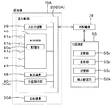
図1は、牧草管理システムの全体図を示している。牧草管理システムは、圃場の牧草を成形して排出可能な成形機10Aに関し、当該成形機10Aによって成形した成形材の排出に関する設定をすることが可能なシステムである。
Embodiments of the present invention will be described below with reference to the drawings.
[First Embodiment]
FIG. 1 shows an overall view of a grass management system. The grass management system is a system capable of setting the discharge of the molding material molded by the molding machine 10A, which is related to the molding machine 10A capable of molding and discharging grass in the field.

まず、成形機10Aについて説明する。
成形機10Aは、圃場の牧草を収集して、収集した作物をロール状や矩形状(キューブ状)の所定形状に成形する機械である。成形機10Aは、例えば、牧草をロール状に成形するロールベーラ、ホールクロップ、矩形状に成形するヘイベーラ等である。
図2に示すように、成形機10Aは、走行車両20と、成形装置30Aとを備えている。走行車両20は、トラクタである。走行車両20は、車体21と、原動機22と、変速装置23とを備えている。車体21には、走行装置24が設けられている。走行装置24は、前輪及び後輪を有する装置である。走行装置24は、クローラ型の装置であってもよい。原動機22は、ディーゼルエンジン、電動モータ等であって、この実施形態ではディーゼルエンジンで構成されている。変速装置23は、走行装置24の推進力を切換可能で
あると共に、走行装置24の前進、後進の切換が可能である。また、車体21の後部には、3点リンク機構等で構成された連結部25が設けられている。連結部25には、成形装置30Aが着脱可能である。成形装置30Aを連結部25に連結することによって、車体21によって成形装置30Aを牽引することができる。また、走行車両20は、原動機22等の動力によって駆動するPTO軸を有し、PTO軸の動力を作業装置に伝達可能である。また、走行車両20は、運転席を内部に備えたキャビン26を備えている。
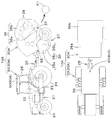
First, the molding machine 10A will be described.
The forming machine 10A is a machine that collects grass in the field and forms the collected crop into a predetermined shape such as a roll shape or a rectangular shape (cube shape). The molding machine 10A is, for example, a roll baler for forming grass into a roll shape, a hole crop, a hay baler for forming a rectangular shape, or the like.
As shown in FIG. 2, the molding machine 10A includes a traveling vehicle 20 and a molding device 30A. The traveling vehicle 20 is a tractor. The traveling vehicle 20 includes a vehicle body 21, a prime mover 22, and a transmission 23. A traveling device 24 is provided on the vehicle body 21. The traveling device 24 is a device having front wheels and rear wheels. The traveling device 24 may be a crawler type device. The prime mover 22 is a diesel engine, an electric motor, or the like, and is composed of a diesel engine in this embodiment. The speed change device 23 can switch the propulsive force of the traveling device 24, and can also switch the traveling device 24 between forward and reverse. Further, at the rear part of the vehicle body 21, there is provided a connecting part 25 composed of a three-point link mechanism or the like. A molding device 30A can be attached to and detached from the connecting portion 25. By connecting the molding device 30A to the connecting portion 25, the molding device 30A can be pulled by the vehicle body 21. Further, the traveling vehicle 20 has a PTO shaft driven by the power of the prime mover 22 and the like, and the power of the PTO shaft can be transmitted to the work device. The traveling vehicle 20 also includes a cabin 26 having a driver's seat inside.

図1に示すように、走行車両20は、USBメモリ、SDカード等の電子記憶媒体である外部機器28が接続される入出力装置29を備えている。入出力装置29は、制御装置40等に接続されていて、走行車両20等の情報(データ)を外部機器28に書き込んだり、外部機器28の情報を取得することが可能である。
図2に示すように、成形装置30Aは、移動(走行)可能な車体27と、車体27に支持され且つ牧草を取り入れる取入部35を備えている。取入部35は、刈り取られた圃場上の牧草を前方(走行車両20側)から取り入れる装置であって、例えば、前方が開放状であるケーシング35aを有している。また、取入部35は、ケーシング35a等に支持された回転軸35bと、回転軸35bに固定された案内具35cを有している。したがって、回転軸35bを回転することによって、圃場上の牧草を案内具35cによりケーシング35a内へ取り入れることができる。なお、図2の取入部35は一例であり、上述した取入部35に限定されない。
As shown in FIG. 1, the traveling vehicle 20 includes an input/output device 29 to which an external device 28, which is an electronic storage medium such as a USB memory or an SD card, is connected. The input/output device 29 is connected to the control device 40 and the like, and is capable of writing information (data) of the traveling vehicle 20 and the like to the external device 28 and acquiring information of the external device 28.
As shown in FIG. 2, the molding device 30A includes a movable (running) vehicle body 27, and an intake section 35 that is supported by the vehicle body 27 and takes in grass. The intake unit 35 is a device that takes in the cut grass on the field from the front (the traveling vehicle 20 side), and has, for example, a casing 35a whose front is open. Further, the intake portion 35 has a rotating shaft 35b supported by the casing 35a and the like, and a guide tool 35c fixed to the rotating shaft 35b. Therefore, by rotating the rotary shaft 35b, the grass on the field can be taken into the casing 35a by the guide 35c. Note that the intake unit 35 in FIG. 2 is an example, and is not limited to the above-described intake unit 35.

成形装置30Aは、収容部36と、排出部37とを備えている。収容部36は、取入部35により取り入れられた牧草を収容するケースである。排出部37は、牧草を圃場に排出する部位である。収容部36は、車体27に固定された第1ケース体36aと、第1ケース体36aに対して上下に揺動自在な第2ケース体36bとを有している。第1ケース体36aと取入部35とは連通していて、第1ケース体36aには、取入部35に取り入れられた牧草が入る。第1ケース体36aに対して第2ケース体36bを近接させている状態(下方に揺動した状態)では、牧草を収容した状態(収容状態)となる。また、第1ケース体36aに対して第2ケース体36bを離間させている状態(上方に揺動した状態)では、牧草を排出した状態となる。即ち、排出部37は、第1ケース体36aに対して第2ケース体36bを上方に揺動した時に、第1ケース体36aと、第2ケース体36bとの間に形成される。したがって、収容部36によって牧草を収容することができ、排出部37によって牧草を排出することができる。なお、図2の収容部36及び排出部37は一例であり、上述した収容部36及び排出部37に限定されない。なお、説明の便宜上、第1ケース体36aに対して第2ケース体36bを下方に揺動した状態のことを閉鎖状態(ゲート閉鎖状態)といい、第1ケース体36aに対して第2ケース体36bを上方に揺動した状態のことを開放状態(ゲート開放状態)ということがある。 The molding device 30A includes a housing portion 36 and a discharge portion 37. The accommodating part 36 is a case for accommodating the grass taken in by the intake part 35. The discharge part 37 is a part for discharging the grass to the field. The accommodating portion 36 has a first case body 36a fixed to the vehicle body 27 and a second case body 36b swingable up and down with respect to the first case body 36a. The first case body 36a and the intake section 35 communicate with each other, and the grass taken into the intake section 35 enters the first case body 36a. In the state where the second case body 36b is brought close to the first case body 36a (the state where the second case body 36b is swung downward), the grass is accommodated (accommodation state). Further, in the state where the second case body 36b is separated from the first case body 36a (the state where the second case body 36b is swung upward), the grass is discharged. That is, the discharge portion 37 is formed between the first case body 36a and the second case body 36b when the second case body 36b is swung upward with respect to the first case body 36a. Therefore, the storage portion 36 can store the grass, and the discharge portion 37 can discharge the grass. It should be noted that the accommodation portion 36 and the ejection portion 37 of FIG. 2 are merely examples, and are not limited to the accommodation portion 36 and the ejection portion 37 described above. For convenience of explanation, a state in which the second case body 36b is swung downward with respect to the first case body 36a is called a closed state (gate closed state), and the first case body 36a is in the second case. The state in which the body 36b is swung upward may be referred to as an open state (gate open state).

成形装置30Aは、成形部38を備えている。成形部38は、取入部35に取り入れた牧草を成形する。即ち、成形部38は、第1ケース体36a及び第2ケース体36bに設けられ、収容した牧草を成形する。成形部38は、例えば、複数の回転ローラによってロール状の成形材K1を成形する装置である。成形部38は、牧草をチェーンによってロール状に成形するチェーン式の装置であっても、ベルトによってロール形状にするベルト式の装置であっても、その他の方式の装置であってもよい。したがって、成形部38は、収容部36に取り込まれた牧草を所定の形状に成形することができる。 The molding device 30A includes a molding unit 38. The forming unit 38 forms the grass that has been taken into the intake unit 35. That is, the molding part 38 is provided in the first case body 36a and the second case body 36b and molds the stored grass. The molding unit 38 is, for example, a device that molds the roll-shaped molding material K1 with a plurality of rotating rollers. The forming unit 38 may be a chain type device for forming grass into a roll shape by a chain, a belt type device for forming a roll shape with a belt, or any other type of device. Therefore, the forming unit 38 can form the grass taken into the housing unit 36 into a predetermined shape.

図1及び図2に示すように、成形機10Aは、位置検出部90(位置検出部90A)を備えている。位置検出部90Aは、走行車両20のキャビン26の天板に装着されている。なお、位置検出部90Aは、キャビン26の天板に装着されているが、走行車両20における装着場所は限定されず、別の場所であってもよい。また、位置検出部90Aは、成形装置30Aに装着されていてもよい。 As shown in FIGS. 1 and 2, the molding machine 10A includes a position detector 90 (position detector 90A). The position detector 90A is mounted on the top plate of the cabin 26 of the traveling vehicle 20. Although the position detection unit 90A is mounted on the top plate of the cabin 26, the mounting position on the traveling vehicle 20 is not limited and may be another position. Further, the position detection unit 90A may be mounted on the molding device 30A.

位置検出部90Aは、衛星測位システムによって自己の位置(緯度、経度を含む測位情報)を検出する位置検出装置である。即ち、位置検出部90Aは、測位衛星から送信された信号(測位衛星の位置、送信時刻、補正情報等)を受信し、受信した信号に基づいて位置(例えば、緯度、経度)を検出する。したがって、成形機10に位置検出部90Aを設
けているため、牧草に関する作業時(走行時)の位置(成形作業時の機械位置)を検出することができる。
The position detection unit 90A is a position detection device that detects its own position (positioning information including latitude and longitude) by the satellite positioning system. That is, the position detection unit 90A receives a signal (position of the positioning satellite, transmission time, correction information, etc.) transmitted from the positioning satellite, and detects the position (eg, latitude, longitude) based on the received signal. Therefore, since the molding machine 10 is provided with the position detection unit 90A, it is possible to detect the position (machine position during molding work) during grass work (running).

図1に示すように、成形機10Aは、制御装置(制御部)40を備えている。制御装置40は、走行車両20に設けられている。制御装置40は、運転席の周りに設置された操作具(レバー、スイッチ、ボリューム等)を操作したときの操作信号、走行車両20に搭載された様々なセンサ(検出装置)の検出信号等に基づいて走行車両20の制御を行う。
具体的には、制御装置40には、クランク位置を検出するセンサ41a、カム位置を検出するセンサ41b、原動機22の回転数(エンジン回転数)を検出するセンサ41cが接続されている。制御装置41は、センサ41a〜41c等で検出されたクランク位置、カム位置、エンジン回転数等の信号に基づいて求めた制御信号を、インジェクタ、コモンレール、サプライポンプ等に出力することで、原動機(エンジン)22を制御する。なお、インジェクタの制御では燃料噴射量、噴射時期、燃料噴射率が示された制御信号を当該インジェクタに出力する。また、サプライポンプやコモンレールの制御では燃料噴射圧等が示された信号を、当該サプライポンプやコモンレールに出力する。なお、制御装置40による原動(エンジン)22の制御は一例であり、限定されない。
As shown in FIG. 1, the molding machine 10A includes a control device (control unit) 40. The control device 40 is provided in the traveling vehicle 20. The control device 40 receives an operation signal when operating an operation tool (lever, switch, volume, etc.) installed around the driver's seat, a detection signal of various sensors (detection devices) mounted on the traveling vehicle 20, and the like. Based on this, the traveling vehicle 20 is controlled.
Specifically, the control device 40 is connected to a sensor 41a that detects a crank position, a sensor 41b that detects a cam position, and a sensor 41c that detects a rotation speed (engine speed) of the prime mover 22. The control device 41 outputs a control signal obtained based on signals such as crank position, cam position, and engine speed detected by the sensors 41a to 41c to an injector, a common rail, a supply pump, etc. Engine) 22 is controlled. In the control of the injector, a control signal indicating the fuel injection amount, injection timing, and fuel injection rate is output to the injector. Further, in the control of the supply pump or the common rail, a signal indicating the fuel injection pressure or the like is output to the supply pump or the common rail. The control of the prime mover (engine) 22 by the control device 40 is an example, and is not limited.

また、制御装置40には、例えば、操作具として連結部25を昇降する昇降レバー42と、連結部を作動させる油圧シリンダを伸縮させる電磁制御弁(図示省略)とが接続されている。制御装置40は、昇降レバー42が操作されると、電磁制御弁に制御信号を出力して当該電磁制御弁の開度を設定し、油圧シリンダを伸縮させることで連結部を昇降させる。 Further, for example, an elevating lever 42 that elevates and lowers the connecting portion 25 as an operation tool, and an electromagnetic control valve (not shown) that extends and contracts a hydraulic cylinder that operates the connecting portion are connected to the control device 40. When the elevating lever 42 is operated, the control device 40 outputs a control signal to the electromagnetic control valve to set the opening degree of the electromagnetic control valve and expands and contracts the hydraulic cylinder to elevate and lower the connecting portion.

また、成形機10Aは、表示装置48を備えている。表示装置48は、走行車両20に設けられている。表示装置48は、運転席の近傍に設けられている。表示装置48は制御装置40に接続され、当該制御装置40と信号(データ)のやり取りが可能である。表示装置48は、タッチパネル、スイッチ等の入力インターフェースが設けられ、成形機10Aに関する様々な情報を画面M2に表示する。例えば、図3Aに示すように、表示装置48は、走行車両20の状態を示すアイコン48aを画面M2に表示したり、走行車両20又は成形装置30Aの設定を行う設定部48bを画面M2に表示する。なお、表示装置48が表示する情報は上述した例に限定されない。 Further, the molding machine 10A includes a display device 48. The display device 48 is provided on the traveling vehicle 20. The display device 48 is provided near the driver's seat. The display device 48 is connected to the control device 40 and can exchange signals (data) with the control device 40. The display device 48 is provided with an input interface such as a touch panel and a switch, and displays various information regarding the molding machine 10A on the screen M2. For example, as shown in FIG. 3A, the display device 48 displays an icon 48a indicating the state of the traveling vehicle 20 on the screen M2 or a setting unit 48b for setting the traveling vehicle 20 or the molding device 30A on the screen M2. To do. The information displayed by the display device 48 is not limited to the above example.

牧草管理システムは、成形材K1の排出を禁止する禁止位置を設定する禁止設定部50Aを備えている。禁止設定部50Aは、支援装置55に設けられている。支援装置55は、例えば、牧草の管理をする管理者が所有するパーソナルコンピュータ等である。なお、支援装置55は、スマートフォン、タブレット、PDA等の携帯端末等であってもよいし、サーバ等であってもよい。 The grass management system includes a prohibition setting unit 50A that sets a prohibition position that prohibits the discharge of the molding material K1. The prohibition setting unit 50A is provided in the support device 55. The support device 55 is, for example, a personal computer or the like owned by an administrator who manages grass. The support device 55 may be a mobile terminal such as a smartphone, a tablet, a PDA, or the like, or may be a server or the like.

支援装置55は、CPU等から構成された演算部55aと、表示部55bと、不揮発性のメモリ等から構成された記憶部55cを有している。また、支援装置55は、外部機器28を接続可能な接続部を有している。表示部55bは、様々な表示を行う装置で液晶パネル等から構成されている。禁止設定部50Aは、支援装置55に設けられた電気・電子部品、当該演算部55a(支援装置55)等に組み込まれたプログラム等から構成されている。 The support device 55 has a calculation unit 55a configured by a CPU or the like, a display unit 55b, and a storage unit 55c configured by a non-volatile memory or the like. In addition, the support device 55 has a connecting portion to which the external device 28 can be connected. The display unit 55b is a device that performs various displays and is composed of a liquid crystal panel or the like. The prohibition setting unit 50A is composed of electric/electronic parts provided in the support device 55, a program installed in the calculation unit 55a (support device 55), and the like.

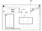
図4Aに示すように、支援装置55を管理者等が操作すると、禁止設定部50Aは、当該支援装置55の表示部55bに設定画面M1を表示させる。設定画面M1は、圃場を設定する設定部101と、圃場を示すフィールド102を表示する圃場表示部103とを有している。設定部101では、管理者等が予め支援装置55に登録した圃場に対応する圃場名、圃場を示す圃場コード等の識別情報を選択可能である。圃場表示部103には、設定部101で選択された識別情報(圃場名、圃場コード)に対応するフィールド102が表示される。 As shown in FIG. 4A, when an administrator or the like operates the support device 55, the prohibition setting unit 50A causes the display unit 55b of the support device 55 to display the setting screen M1. The setting screen M1 has a setting unit 101 for setting a field and a field display unit 103 for displaying a field 102 indicating the field. In the setting unit 101, an administrator or the like can select identification information such as a field name and a field code indicating a field registered in the support device 55 in advance. A field 102 corresponding to the identification information (field name, field code) selected by the setting section 101 is displayed on the field display section 103.

フィールド102には、圃場の位置(緯度、経度)が対応付けられている。例えば、支援装置55の記憶部55cには、予め圃場の位置を示す位置情報が記憶されており、禁止設定部50Aは、圃場表示部103にフィールド102を表示する際に記憶部55cを参照して、設定部101に示された識別情報に対応する位置と、フィールド102とを対応
させる。或いは、禁止設定部50Aは、圃場表示部103にフィールド102を表示後、フィールド102の任意の点(基準位置)に対する緯度、経度の情報を入力するように管理者等に要求し、管理者が入力インタフェース(マウス、キーボード等)を用いて入力した基準位置に対する位置(緯度、経度)に基づき、フィールド102上の全ての点に緯度、経度を割り当てる。
The field 102 is associated with the field position (latitude, longitude). For example, the storage unit 55c of the support device 55 stores position information indicating the position of the field in advance, and the prohibition setting unit 50A refers to the storage unit 55c when displaying the field 102 on the field display unit 103. Then, the field 102 is associated with the position corresponding to the identification information shown in the setting unit 101. Alternatively, the prohibition setting unit 50A, after displaying the field 102 on the field display unit 103, requests the administrator or the like to input information on the latitude and longitude for an arbitrary point (reference position) of the field 102, and the administrator Based on the position (latitude, longitude) with respect to the reference position input using the input interface (mouse, keyboard, etc.), latitude and longitude are assigned to all points on the field 102.

フィールド102には、成形材K1の排出を禁止する禁止位置が設定可能である。例えば、禁止設定部50Aは、管理者が支援装置55の入力インタフェースを用いて、フィールド102上の所定範囲A1を選択後、設定画面M1に表示された登録ボタン104を選択すると、フィールと102上における所定範囲A1を成形材K1の排出を禁止する禁止エリアに設定する。例えば、図4Aに示すように、フィールド102上において、位置P1と位置P2とを選択した場合、禁止設定部50Aは、位置P1と位置P2とを結ぶ対角線を囲む禁止エリアA1に含まれる全ての位置を、禁止位置に設定する。設定画面M1では、図4Bに示すように、入力インターフェースを用いて、フィールド102に対して複数の禁止エリアA1、A2を選択することにより、当該複数の禁止エリアA1、A2の全ての位置を禁止位置として設定することができる。 In the field 102, a prohibition position for prohibiting the ejection of the molding material K1 can be set. For example, when the administrator uses the input interface of the support device 55 to select the predetermined range A1 on the field 102 and then selects the registration button 104 displayed on the setting screen M1, the prohibition setting unit 50A displays the field and the field 102. The predetermined range A1 in is set as a prohibited area in which the discharge of the molding material K1 is prohibited. For example, as shown in FIG. 4A, when the position P1 and the position P2 are selected on the field 102, the prohibition setting unit 50A includes all prohibition areas A1 surrounding a diagonal line connecting the position P1 and the position P2. Set the position to a prohibited position. On the setting screen M1, as shown in FIG. 4B, by selecting a plurality of prohibited areas A1 and A2 for the field 102 using the input interface, all positions of the plurality of prohibited areas A1 and A2 are prohibited. It can be set as a position.

なお、フィールド102上を選択することによる禁止位置の設定方法は、上述した例に限定されない。また、圃場表示部103は、フィールド102に圃場を示す画像を示してもよいし、圃場の地図を示してもよいし、その他の圃場に関する情報を重ねて表示してもよい。
図5は、禁止設定部50Aによって設定した禁止位置と、圃場の位置(フィールド102の位置)と、禁止エリアA1との一例を示している。設定画面M1(禁止設定部50A)によって設定した禁止位置(図5に示した禁止位置)は、禁止情報として記憶部55cに記憶される。なお、禁止位置と、圃場を識別する識別情報(圃場名、圃場コード等)とを禁止情報として記憶部55cに記憶してもよい。禁止位置の設定後、USB等の外部機器28を支援装置55に接続することにより、記憶部55cに記憶した禁止位置情報は、外部機器28に転送することができる。
The method of setting the prohibited position by selecting the field 102 is not limited to the above-described example. Further, the farm field display unit 103 may display an image showing the farm field in the field 102, may display a map of the farm field, and may display information regarding other farm fields in an overlapping manner.
FIG. 5 shows an example of a prohibited position set by the prohibition setting unit 50A, a field position (position of the field 102), and a prohibited area A1. The prohibition position (prohibition position shown in FIG. 5) set by the setting screen M1 (prohibition setting unit 50A) is stored in the storage unit 55c as prohibition information. Note that the prohibited position and the identification information (field name, field code, etc.) for identifying the field may be stored in the storage unit 55c as the prohibition information. After setting the prohibited position, the prohibited position information stored in the storage unit 55c can be transferred to the external device 28 by connecting the external device 28 such as a USB to the support device 55.

したがって、圃場表示部103に圃場を示すフィールド102を表示してフィールド102の禁止エリアを選択することにより、オペレータ等が任意に禁止位置を設定することができる。
さて、成形機10Aは、禁止位置取得部を備えている。禁止位置取得部は、成形材K1の排出を禁止する禁止位置を取得する装置である。この実施形態では、禁止位置取得部は、外部機器28が接続可能な入出力装置29である。禁止情報を記憶した外部機器28を、入出力装置29に接続すると、当該入出力装置29は、外部機器28に記憶された禁止位置を含む禁止情報を取得する。取得した禁止情報は、制御装置40に設けられた記憶部40aに記憶される。
Therefore, by displaying the field 102 indicating the field on the field display unit 103 and selecting the prohibited area of the field 102, the operator or the like can arbitrarily set the prohibited position.
Now, the molding machine 10A includes a prohibited position acquisition unit. The prohibited position acquisition unit is a device that acquires a prohibited position at which the ejection of the molding material K1 is prohibited. In this embodiment, the prohibited position acquisition unit is the input/output device 29 to which the external device 28 can be connected. When the external device 28 storing the prohibition information is connected to the input/output device 29, the input/output device 29 acquires the prohibition information including the prohibition position stored in the external device 28. The acquired prohibition information is stored in the storage unit 40a provided in the control device 40.

制御装置(制御部)40は、排出部37から成形材K1を排出する排出位置(排出予定位置)と、禁止位置取得部(入出力装置29)が取得した禁止位置との関係に基づいて制御を行う。
図1に示すように、成形機10Aは、排出操作部43を備えている。排出操作部43は、排出部37による成形材K1の排出を操作する操作具であって、例えば、ON/OFFに切換可能なスイッチである。排出操作部43は、運転席の近傍に設けられていて、オペレータが操作可能である。排出操作部43をONにすると、排出指令信号が制御装置40に入力され、排出操作部43をOFFにすると、排出停止信号が制御装置40に入力される。なお、排出操作部43は、表示装置48に表示したON/OFFに切り換え可能なスイッチであってもよい。入出力装置29を、表示装置48に設けてもよい。
The control device (control unit) 40 performs control based on the relationship between the discharge position (scheduled discharge position) for discharging the molding material K1 from the discharge unit 37 and the prohibited position acquired by the prohibited position acquisition unit (input/output device 29). I do.
As shown in FIG. 1, the molding machine 10A includes a discharge operation unit 43. The discharge operation unit 43 is an operation tool for operating the discharge of the molding material K1 by the discharge unit 37, and is, for example, a switch that can be switched ON/OFF. The discharge operation unit 43 is provided near the driver's seat and can be operated by the operator. When the discharge operation part 43 is turned on, a discharge command signal is input to the control device 40, and when the discharge operation part 43 is turned off, a discharge stop signal is input to the control device 40. The discharge operation unit 43 may be a switch that can be switched ON/OFF displayed on the display device 48. The input/output device 29 may be provided in the display device 48.

図6に示すように、成形機10Aが圃場上の牧草を収集(回収)しながら成形する成形作業時において、オペレータが排出操作部43をOFFからONに切り換えた場合、制御装置40は、当該排出操作部43がOFFからONになった機械位置P7を、成形材K1の排出位置DW1として設定する。また、排出操作部43をOFFからONに切り換えた時点の機械位置(切換時の機械位置)P7から数m〜数十m先の位置を、排出位置DW1
としてもよい。つまり、排出操作部43をOFFからONに切り換えてから成形材K1が圃場に排出されるまでの成形機10Aの走行距離を予め設定しておき、切換時の機械位置に予め設定された走行距離を加算した位置を、排出位置DW1としてもよい。なお、上述した排出位置DW1の設定は一例であり、限定されない。
As shown in FIG. 6, when the molding machine 10A molds the grass while collecting (collecting) the grass on the field, when the operator switches the discharging operation unit 43 from OFF to ON, the control device 40 is The machine position P7 in which the discharge operation unit 43 is turned from OFF to ON is set as the discharge position DW1 of the molding material K1. Further, a position several m to several tens m ahead of the machine position (machine position at the time of switching) P7 at the time when the discharge operation unit 43 is switched from OFF to ON is the discharge position DW1.
May be That is, the traveling distance of the molding machine 10A from when the discharge operation unit 43 is switched from OFF to ON until the molding material K1 is discharged to the field is set in advance, and the traveling distance set in advance in the machine position at the time of switching is set. The position obtained by adding the values may be set as the discharge position DW1. The setting of the discharge position DW1 described above is an example, and is not limited.

このとき、制御装置40は、排出位置DW1を設定後、記憶部40aに記憶された禁止情報を参照し、排出操作部43により設定された排出位置DW1が、禁止位置に設定されているか否かを判断する。即ち、制御装置40は、排出位置DW1と禁止位置とが一致しているか否かを判断する。
制御装置40は、排出位置DW1と禁止位置とが一致していない場合、成形材K1の排出を許可し、例えば、第2ケース体36bに接続された油圧シリンダを伸縮させる切換弁等に対して、制御信号を出力することで、油圧シリンダを伸長させ、成形装置30Aをゲート開放状態にする。
At this time, the control device 40 refers to the prohibition information stored in the storage unit 40a after setting the discharge position DW1, and determines whether the discharge position DW1 set by the discharge operation unit 43 is set to the prohibition position. To judge. That is, the control device 40 determines whether or not the discharge position DW1 and the prohibited position match.
When the discharge position DW1 and the prohibition position do not coincide with each other, the control device 40 permits the discharge of the molding material K1 and, for example, for a switching valve that expands and contracts the hydraulic cylinder connected to the second case body 36b. By outputting the control signal, the hydraulic cylinder is extended and the molding apparatus 30A is opened.

一方、制御装置40は、排出位置DW1と禁止位置とが一致している場合、成形材K1の排出を許可せず、油圧シリンダを収縮した状態に維持し、成形装置30Aをゲート閉鎖状態に保持する。即ち、制御装置40は、オペレータが排出操作部43をOFFからONの状態に切り換えたとしても、成形装置30Aをゲート開放状態に移行しない。
したがって、成形機10Aによる成形作業時に、禁止位置に設定された場所に成形材K1を排出することを防止することができる。
On the other hand, when the discharge position DW1 and the prohibited position match, the control device 40 does not permit the discharge of the molding material K1, maintains the hydraulic cylinder in a contracted state, and holds the molding device 30A in the gate closed state. To do. That is, the control device 40 does not shift the molding device 30A to the gate open state even if the operator switches the discharge operation unit 43 from the OFF state to the ON state.
Therefore, during the molding operation by the molding machine 10A, it is possible to prevent the molding material K1 from being discharged to the place set to the prohibited position.

また、制御装置40は、排出位置が禁止位置に一致している場合、表示装置48に対して排出位置が禁止位置に一致していることを示す制御信号を出力する。表示装置48は、制御装置40からの制御信号(制御)に応答して、排出位置と禁止位置とが一致していることを示す表示を実行する。例えば、図3Bに示すように、表示装置48は、成形機10Aに関する情報を画面M2に表示した状況において、当該情報を表示する画面M2上に、ポップアップしたポップアップ画面M3を表示し、ポップ画面M3に排出位置と禁止位置とが一致していることを示す表示を示す。なお、上述した実施形態において、排出操作部43は、表示装置48に表示したON/OFFに切り換え可能なスイッチであってもよい。入出力装置29を、表示装置48に設けてもよい。 Further, when the ejection position coincides with the prohibition position, the control device 40 outputs a control signal indicating that the ejection position coincides with the prohibition position to the display device 48. The display device 48 responds to a control signal (control) from the control device 40 and executes a display indicating that the ejection position and the prohibition position match. For example, as shown in FIG. 3B, in the situation where the information on the molding machine 10A is displayed on the screen M2, the display device 48 displays a pop-up screen M3 that pops up on the screen M2 displaying the information, and the pop screen M3. Shows a display indicating that the discharge position and the prohibited position match. In the above-described embodiment, the discharge operation unit 43 may be a switch that is displayed on the display device 48 and that can be switched ON/OFF. The input/output device 29 may be provided in the display device 48.

したがって、排出位置DW1と禁止位置とが一致した場合には、成形材K1の排出を行わず、排出位置DW1と禁止位置とが一致にない場合のみ、成形材K1の排出を行うことができる。即ち、成形機10Aによる成形作業時に、禁止位置に設定された場所に成形材K1を排出することを防止することができる。
[第2実施形態]
図7は、第2実施形態における牧草管理システムの全体図を示している。第2実施形態では、上述した実施形態と異なる構成について説明する。図7に示すように、牧草管理システムは、禁止位置を設定する禁止設定部50Bを備えている。禁止設定部50Bは、作業機の走行時における情報に基づいて禁止位置を設定する。
Therefore, when the discharge position DW1 and the prohibited position match, the molding material K1 is not discharged, and the molding material K1 can be discharged only when the discharge position DW1 and the prohibited position do not match. That is, it is possible to prevent the molding material K1 from being discharged to the place set as the prohibited position during the molding operation by the molding machine 10A.
[Second Embodiment]
FIG. 7 shows an overall view of the grass management system in the second embodiment. In the second embodiment, a configuration different from the above embodiments will be described. As shown in FIG. 7, the grass management system includes a prohibition setting unit 50B that sets a prohibition position. The prohibition setting unit 50B sets the prohibition position based on information when the working machine is traveling.

作業機は、牧草に関する作業を行う機械である。作業機は、成形機10A、草刈機10B、拡散機10C、集草機10D等である。つまり、第2実施形態は、成形機10A、草刈機10B、拡散機10C、集草機10Dのいずれかの走行時における情報に基づいて、禁止位置を設定することが可能である。
まず、草刈機10B、拡散機10C、集草機10Dの概略について説明する。
The work machine is a machine that performs work on grass. The working machines are a molding machine 10A, a mower 10B, a spreader 10C, a grass collector 10D, and the like. That is, in the second embodiment, it is possible to set the prohibited position based on the information when any one of the molding machine 10A, the mower 10B, the spreader 10C, and the grass collector 10D is running.
First, an outline of the mower 10B, the spreader 10C, and the grass collector 10D will be described.

図8に示すように、草刈機10Bは、牧草を刈り取る機械であって、走行車両20と、走行車両20に連結された刈取装置30Bとを有している。刈取装置30Bは、走行車両20の連結部25に連結する連結フレーム62と、連結フレーム62に連結された刈取部63とを有している。刈取部63は、刈取する牧草を取り入れる取入部65と、取入部65により取り入れられた牧草を切断する複数の切断部66とを有している。なお、図8では、刈取装置30Bが有する複数の切断部66のうち、1つの切断部66を示している。 As shown in FIG. 8, the mowing machine 10B is a machine for cutting grass and has a traveling vehicle 20 and a mowing device 30B connected to the traveling vehicle 20. The mowing device 30B has a connecting frame 62 that is connected to the connecting part 25 of the traveling vehicle 20, and a mowing unit 63 that is connected to the connecting frame 62. The reaping unit 63 has an intake unit 65 for taking in the grass to be cut and a plurality of cutting units 66 for cutting the grass taken in by the taking unit 65. In addition, in FIG. 8, one cutting part 66 is shown among the plurality of cutting parts 66 included in the reaping device 30B.

切断部66は、複数の回転軸67と、回転軸67に取り付けられた複数のカッター68とを有している。PTO軸の動力は、連結フレーム62に支持された駆動軸を介して回転軸67に伝達され、回転軸67は回転する。カッター68は、ディスク状のカッターであ
って、隣接して並ぶカッター68が回転軸67の回転に伴って回転することで牧草を刈り取る。即ち、回転軸67によって、カッター68は回転し、カッター68によって牧草は刈り取られ、牧草は刈取後、外部に排出される。なお、刈取装置30Bは、上述した構成に限定されず、牧草を刈り取る装置であればよい。例えば、刈取装置30Bは、ナイフ状のカッター68によって牧草を刈り取るハンマーナイフ式であっても、その他の方式であってもよい。
The cutting unit 66 has a plurality of rotating shafts 67 and a plurality of cutters 68 attached to the rotating shafts 67. The power of the PTO shaft is transmitted to the rotary shaft 67 via the drive shaft supported by the connecting frame 62, and the rotary shaft 67 rotates. The cutters 68 are disk-shaped cutters, and the cutters 68 arranged adjacent to each other rotate with the rotation of the rotary shaft 67 to cut grass. That is, the cutter 68 is rotated by the rotating shaft 67, the grass is cut by the cutter 68, and the grass is discharged after being cut. The harvesting device 30B is not limited to the above-mentioned configuration, and may be any device that harvests grass. For example, the mowing device 30B may be of a hammer knife type for cutting grass by a knife-shaped cutter 68, or may be of another type.

図9に示すように、拡散機10Cは、刈取後の牧草を拡散する機械であって、走行車両20と、走行車両20に連結された拡散装置30Cとを有している。拡散装置30Cは、走行装置20の連結部25に連結する連結フレーム72と、連結フレーム72に連結された拡散部73とを有している。なお、図9では、連結フレーム72に2つの拡散部73を連結した例を示している。 As shown in FIG. 9, the spreader 10C is a machine that spreads grass after cutting and has a traveling vehicle 20 and a diffusion device 30C connected to the traveling vehicle 20. The diffusing device 30C includes a connecting frame 72 that is connected to the connecting part 25 of the traveling device 20, and a diffusing part 73 that is connected to the connecting frame 72. Note that FIG. 9 shows an example in which two diffusion units 73 are connected to the connection frame 72.

拡散部73は、連結フレーム72に連結された本体74と、本体74に回転自在に支持された回転軸75と、回転軸75に連結された複数のアーム(タインアーム)76と、複数のアーム76それぞれに連結された拡散具(タイン)77とを有している。タイン77は、例えば、先端が二叉に分かれた部材である。PTO軸の動力は、連結フレーム72に支持された駆動軸を介して回転軸75に伝達され、回転軸75は回転する。回転軸75の回転に伴ってアーム76が回転し、拡散具77によって牧草を拡散する。即ち、回転軸75の回転によって拡散具77は回転し、拡散具77によって牧草は拡散される。なお、拡散装置30Cは、上述した構成に限定されず、牧草を拡散する装置であればよい。例えば、拡散部73は、1つ又は3つ以上であってもよい。また、拡散部73は、拡散具77の付いたローターが縦軸回りに回転するロータリー型であっても、回転するベルトやチェーンに複数の拡散具77を取付けたベルト/チェーン型であっても、その他の方式であってもよい。 The diffusion unit 73 includes a main body 74 connected to the connection frame 72, a rotating shaft 75 rotatably supported by the main body 74, a plurality of arms (tine arms) 76 connected to the rotating shaft 75, and a plurality of arms 76. It has a diffuser (tine) 77 connected to each. The tine 77 is, for example, a member whose tip is bifurcated. The power of the PTO shaft is transmitted to the rotary shaft 75 via the drive shaft supported by the connecting frame 72, and the rotary shaft 75 rotates. The arm 76 rotates with the rotation of the rotary shaft 75, and the grass is diffused by the diffuser 77. That is, the diffusing tool 77 is rotated by the rotation of the rotating shaft 75, and the grass is diffused by the diffusing tool 77. The diffusing device 30C is not limited to the configuration described above, and may be any device that diffuses grass. For example, the diffusion unit 73 may be one or three or more. The diffusing section 73 may be a rotary type in which the rotor with the diffusing tool 77 rotates around the vertical axis, or a belt/chain type in which a plurality of diffusing tools 77 are attached to a rotating belt or chain. Alternatively, other methods may be used.

図10に示すように、集草機10Dは、牧草を集草する機械であって、走行車両20と、走行車両20に連結された集草装置30Dとを有している。集草装置30Dは、走行車両20の連結部25に連結する連結フレーム82と、連結フレーム82に連結された集草部83とを有している。なお、図10では、連結フレーム82に2つの集草部83を連結した例を示している。 As shown in FIG. 10, the grass collecting machine 10D is a machine for collecting grass and has a traveling vehicle 20 and a grass collecting device 30D connected to the traveling vehicle 20. The grass collecting device 30D includes a connecting frame 82 that is connected to the connecting portion 25 of the traveling vehicle 20 and a grass collecting portion 83 that is connected to the connecting frame 82. Note that FIG. 10 shows an example in which two grass collecting portions 83 are connected to the connecting frame 82.

集草部83は、連結フレーム82に連結された本体84と、本体84に回転自在に支持された回転軸85と、回転軸85に連結された複数のアーム(タインアーム)86と、複数のアーム86それぞれに連結された集草具(タイン)87とを有している。なお、集草装置30Dにおける集草具87の間隔は、拡散装置30Cの拡散具77よりも短い。タイン87は、例えば、先端が二叉に分かれた部材である。PTO軸の動力は、連結フレーム82に支持された駆動軸を介して回転軸85に伝達され、回転軸85は回転する。回転軸85の回転に伴ってアーム86が回転し、集草具87によって牧草を集草する。即ち、回転軸85の回転によって集草具87は回転し、集草具87によって牧草は集草される。 The grass collecting portion 83 includes a main body 84 connected to the connecting frame 82, a rotating shaft 85 rotatably supported by the main body 84, a plurality of arms (tine arms) 86 connected to the rotating shaft 85, and a plurality of arms. 86 and a grass collecting tool (tine) 87 connected to each. The interval of the grass collecting tool 87 in the grass collecting device 30D is shorter than that of the diffusing tool 77 of the diffusing device 30C. The tine 87 is, for example, a member whose tip is bifurcated. The power of the PTO shaft is transmitted to the rotary shaft 85 via the drive shaft supported by the connecting frame 82, and the rotary shaft 85 rotates. The arm 86 rotates with the rotation of the rotating shaft 85, and the grass collecting tool 87 collects grass. That is, the grass collecting tool 87 is rotated by the rotation of the rotary shaft 85, and the grass is collected by the grass collecting tool 87.

なお、集草装置30Dは、上述した構成に限定されず、牧草を集草する装置であればよい。例えば、集草部83は、1つ又は3つ以上であってもよい。また、集草部83は、集草具87の付いたローターが縦軸回りに回転するロータリー型であっても、回転するベルトやチェーンに複数の集草具87を取付けたベルト/チェーン型であっても、その他の方式であってもよい。 The grass collecting device 30D is not limited to the configuration described above, and may be any device that collects grass. For example, the grass collection part 83 may be one or three or more. Further, the grass collecting portion 83 is a belt/chain type in which a plurality of grass collecting tools 87 are attached to a rotating belt or chain even if the rotor with the grass collecting tool 87 rotates about the vertical axis. There may be any other method.

以降、説明の便宜上、成形機10Aの走行車両を「20A」、草刈機10Bの走行車両を「走行車両20B」、拡散機10Cの走行車両を「走行車両20C」、集草機10Dの走行車両を「走行車両20D」ということがある。
さて、図8〜図10に示すように、作業機(草刈機10B、拡散機10C、集草機10D)は、位置検出部90(位置検出部90B、位置検出部90C、位置検出部90D)を有している。
Hereinafter, for convenience of explanation, the traveling vehicle of the molding machine 10A is "20A", the traveling vehicle of the mowing machine 10B is "traveling vehicle 20B", the traveling vehicle of the spreader 10C is "traveling vehicle 20C", and the traveling vehicle of the grass collector 10D. May be referred to as "traveling vehicle 20D".
Now, as shown in FIGS. 8 to 10, the working machine (mowing machine 10B, spreader 10C, grass collector 10D) includes a position detecting section 90 (position detecting section 90B, position detecting section 90C, position detecting section 90D). have.

位置検出部90B、90C、90Dは、走行車両20(走行車両20B、20C、20D)のキャビン26の天板に装着されている。なお、位置検出部90B、90C、90Dは、キャビン26の天板に装着されているが、走行車両20における装着場所は限定され
ず、別の場所であってもよい。
位置検出部90B、90C、90Dは、衛星測位システムによって自己の位置(緯度、経度を含む測位情報)を検出する位置検出装置である。即ち、位置検出部90B、90C、90Dは、測位衛星から送信された信号(測位衛星の位置、送信時刻、補正情報等)を受信し、受信した信号に基づいて位置(例えば、緯度、経度)を検出する。
The position detection units 90B, 90C, 90D are mounted on the top plate of the cabin 26 of the traveling vehicle 20 (traveling vehicles 20B, 20C, 20D). Although the position detectors 90B, 90C, 90D are mounted on the top plate of the cabin 26, the mounting location on the traveling vehicle 20 is not limited and may be another location.
The position detection units 90B, 90C, 90D are position detection devices that detect their own position (positioning information including latitude and longitude) by the satellite positioning system. That is, the position detectors 90B, 90C, 90D receive signals (positioning satellite position, transmission time, correction information, etc.) transmitted from positioning satellites, and position (eg, latitude, longitude) based on the received signals. To detect.

このように、草刈機10B、拡散機10C、集草機10Dのそれぞれに、位置検出部90B、90C、90Dを設けることによって、牧草に関する作業時(走行時)の位置(刈取作業時の機械位置、拡散作業時の機械位置、集草作業時の機械位置)を個別に検出することができる。刈取作業時の機械位置は、走行車両20Bに設けられた記憶部40aに記憶される。拡散作業時の機械位置は、走行車両20Cに設けられた記憶部40aに記憶される。集草作業時の機械位置は、走行車両20Dに設けられた記憶部40aに記憶される。 As described above, by providing the position detectors 90B, 90C, and 90D in each of the mower 10B, the spreader 10C, and the grass collector 10D, the position (mechanical position at the time of cutting) related to the grass is worked (machine position). , Machine position during spreading work, machine position during grass collection work) can be detected individually. The machine position during the mowing operation is stored in the storage unit 40a provided in the traveling vehicle 20B. The machine position during the diffusing work is stored in the storage unit 40a provided in the traveling vehicle 20C. The machine position at the time of grass collection work is stored in the storage unit 40a provided in the traveling vehicle 20D.

図7に示すように、作業機(成形機10A、草刈機10B、拡散機10C、集草機10D)は、操作部91(操作部91A、操作部91B、操作部91C、操作部91D)を備えている。操作部91A、91B、91C、91Dは、成形材K1の排出の禁止を指令するスイッチである。操作部91A、91B、91C、91Dは、ON/OFFに切り換え可能なスイッチであり、制御装置40に接続されている。操作部91A、91B、91C、91Dは、ONである場合は、制御装置40に排出の禁止を指令する禁止信号を出力し、OFFである場合は、制御装置40に排出を許可する許可信号を出力する。操作部91A、91B、91C、91Dは、それぞれ走行車両20A、20B、20C、20Dの運転席の近傍に設けられ、オペレータが操作することができる。即ち、作業機によって牧草に関する作業時(走行中)に、オペレータが圃場の状態を確認して、成形材K1の排出に適していない位置に達した時に、操作部91をONにすれば、禁止位置を設定することができる。 As shown in FIG. 7, the working machine (molding machine 10A, mower 10B, spreader 10C, grass collector 10D) has an operating section 91 (operating section 91A, operating section 91B, operating section 91C, operating section 91D). I have it. The operation units 91A, 91B, 91C, 91D are switches for instructing prohibition of discharge of the molding material K1. The operation units 91A, 91B, 91C, 91D are switches that can be turned ON/OFF and are connected to the control device 40. When the operation units 91A, 91B, 91C, and 91D are ON, the control unit 40 outputs a prohibition signal instructing the discharge prohibition, and when the operation units 91A, 91B, 91C, and 91D are OFF, the operation units 91A, 91B, 91C, and 91D output a permission signal allowing the discharge to the control device 40. Output. The operation units 91A, 91B, 91C, 91D are provided near the driver's seats of the traveling vehicles 20A, 20B, 20C, 20D, respectively, and can be operated by an operator. That is, when the operator confirms the state of the field during the work on the grass by the work machine (during running), and when the operator reaches a position not suitable for discharging the molding material K1, if the operation section 91 is turned on, the prohibition is prohibited. The position can be set.

禁止設定部50Bは、作業機の走行時における情報(機械位置)と、操作部91A、91B、91C、91Dの操作とに基づいて、禁止位置を設定する。禁止設定部50Bは、制御装置40に設けられた電気・電子部品、当該制御装置40等に組み込まれたプログラム等から構成されている。
図11に示すように、草刈機10Bにおける刈取作業時は、位置検出部90Bは刈取作業時の機械位置PBn(n=1,2,3・・・n)を検出する。例えば、草刈機10Bにおける刈取作業時において、機械位置PB3の時点で操作部91BがONになり、制御装置40が禁止信号を取得すると、禁止設定部50Bは、操作部91BのON時における機械位置PB3を保持する。また、刈取作業時において、機械位置PB7で操作部91BがONからOFFに変化すると、禁止設定部50Bは、操作部91BがONからOFFに変化した機械位置PB7を保持する。そして、禁止設定部50Bは、刈取作業時に操作部91BがONされた際の機械位置、即ち、図11では、機械位置PB3〜機械位置PB7までの範囲を禁止エリアに設定する。一方、操作部91BがOFFに維持された状態(制御装置40が許可信号を取得している状態)では、禁止設定部50Bは、刈取作業時の機械位置PBnを禁止位置として設定しない。
The prohibition setting unit 50B sets the prohibition position based on information (machine position) when the work machine is traveling and the operation of the operation units 91A, 91B, 91C, and 91D. The prohibition setting unit 50B is composed of electric/electronic parts provided in the control device 40, programs installed in the control device 40, and the like.
As shown in FIG. 11, during the mowing operation of the mowing machine 10B, the position detector 90B detects the machine position PBn (n=1, 2, 3... N) during the mowing operation. For example, during the mowing operation of the mowing machine 10B, when the operation unit 91B is turned on at the time of the machine position PB3 and the control device 40 acquires the prohibition signal, the prohibition setting unit 50B causes the operation unit 91B to move to the machine position when the operation unit 91B is turned on. Hold PB3. When the operation unit 91B changes from ON to OFF at the machine position PB7 during the mowing work, the prohibition setting unit 50B holds the machine position PB7 in which the operation unit 91B has changed from ON to OFF. Then, the prohibition setting unit 50B sets the machine position when the operation unit 91B is turned on during the mowing work, that is, the range from the machine position PB3 to the machine position PB7 in FIG. 11 to the prohibition area. On the other hand, in the state in which the operation unit 91B is maintained in the OFF state (the state in which the control device 40 obtains the permission signal), the prohibition setting unit 50B does not set the machine position PBn during the mowing work as the prohibition position.

また、拡散機10Cおける拡散作業時は、位置検出部90Cは拡散作業時の機械位置PCn(n=1,2,3・・・n)を検出する。禁止設定部50Bは、拡散作業時において操作部91CのON時における機械位置PCnを禁止位置に設定し、操作部91CのOFF時における機械位置PCnは禁止位置に設定しない。
また、集草機10Dおける集草作業時は、位置検出部90Dは集草作業時の機械位置PDn(n=1,2,3・・・n)を検出する。禁止設定部50Bは、集草作業時において操作部91DのON時における機械位置PDnを禁止位置に設定し、操作部91DのOFF時における機械位置PDnは禁止位置に設定しない。
Further, during the spreading work in the spreader 10C, the position detection unit 90C detects the machine position PCn (n=1, 2, 3,... N) during the spreading work. The prohibition setting unit 50B sets the machine position PCn when the operation unit 91C is ON during the diffusion work to the prohibition position, and does not set the machine position PCn when the operation unit 91C is OFF.
Further, when the grass collecting machine 10D collects grass, the position detector 90D detects the machine position PDn (n=1, 2, 3,... N) during grass collecting work. The prohibition setting unit 50B sets the machine position PDn when the operation unit 91D is ON to the prohibition position during the grass collecting work, and does not set the machine position PDn when the operation unit 91D is OFF.

以上のように、成形機10Aによる成形作業前の作業(刈取作業、拡散作業、集草作業等)において、オペレータが圃場の状態を確認して、成形材K1の排出に適していない位置に達した時に操作部91をONにするだけで、禁止位置を設定することができる。
この実施形態では、刈取作業、拡散作業、集草作業における全ての作業において、禁止位置の設定が行えるとしているが、当然にこれに限定されず、刈取作業、拡散作業、集草作業のいずれかで行えればよい。牧草に関する作業として、刈取作業、拡散作業、集草作業を例示したが、これに限定されず、施肥作業時に行ってもよいし、その他の作業時に行ってもよい。施肥作業にて行う際は、施肥機に、位置検出部90、操作部91、禁止設定部50Bを設けることにより、禁止位置の設定を行うことができる。
As described above, in the work (forming work, spreading work, grass collection work, etc.) before the forming work by the forming machine 10A, the operator confirms the state of the field and reaches the position not suitable for discharging the forming material K1. The prohibited position can be set by simply turning on the operation unit 91 at the time.
In this embodiment, the prohibition position can be set in all of the mowing work, the spreading work, and the grass collecting work. However, the present invention is not limited to this, and any of the mowing work, the spreading work, and the grass collecting work can be performed. You can do it with. Although the cutting work, the spreading work, and the grass collecting work are illustrated as the work related to the grass, the work is not limited to this, and may be performed during the fertilizing work or other work. When performing fertilization work, it is possible to set the prohibited position by providing the fertilizer applicator with the position detection unit 90, the operation unit 91, and the prohibition setting unit 50B.

また、成形機10Aにおける成形作業時においても、禁止位置の設定を行ってもよい。成形機10Aにおいて成形作業時は、位置検出部90Aは成形作業時の機械位置PAn(n=1,2,3・・・n)を検出する。成形機10Aにおける成形作業時において、例えば、オペレータが圃場の状態を確認し、成形材K1の排出に適していないと判断した場合に、操作部91AをONにすることにより、禁止位置を設定することができる。 Further, the prohibited position may be set even during the molding operation in the molding machine 10A. During the molding operation in the molding machine 10A, the position detector 90A detects the machine position PAn (n=1, 2, 3,... N) during the molding operation. During the molding operation in the molding machine 10A, for example, when the operator confirms the state of the field and determines that it is not suitable for discharging the molding material K1, the operation unit 91A is turned on to set the prohibited position. be able to.

上述したように、成形機10A、草刈機10B、拡散機10C、集草機10D、施肥機のいずれにおいても、禁止位置は、それぞれの走行車両20に設けられた制御装置40の記憶部40aに禁止情報として記憶される。禁止位置を含む禁止情報は、走行車両20に設けられた入出力装置29に外部機器28を接続することにより、記憶部40aから外部機器28に転送することができる。また、外部機器28を支援装置55に接続することによって、外部機器28に保存した禁止情報を、支援装置55の記憶部55cに転送することができる。 As described above, in any of the molding machine 10A, the mower 10B, the spreader 10C, the grass collector 10D, and the fertilizer applicator, the prohibited position is stored in the storage unit 40a of the control device 40 provided in each traveling vehicle 20. It is stored as prohibition information. The prohibition information including the prohibition position can be transferred from the storage unit 40a to the external device 28 by connecting the external device 28 to the input/output device 29 provided in the traveling vehicle 20. Further, by connecting the external device 28 to the support device 55, the prohibition information stored in the external device 28 can be transferred to the storage unit 55c of the support device 55.

上述した実施形態では、禁止設定部50Bを制御装置40に設けた例を説明したが、当該禁止設定部50Bを支援装置55に設けてもよい。この場合、禁止設定部50Bは、演算部55a(支援装置55)等に組み込まれたプログラム等から構成される。
この場合、成形機10A、草刈機10B、拡散機10C、集草機10D、施肥機のいずれにおいても、作業時(走行時)において、制御装置40は、操作部91のON/OFFを示す排出設定情報(禁止信号、許可信号)と位置検出部90で検出した機械位置とを対応付けて禁止情報として記憶部40aに記憶する。また、外部機器28を走行車両20の入出力装置29に接続した場合、記憶部40aに記憶されている禁止情報(排出設定情報及び機械位置)は、外部機器28に転送される。外部機器28を支援装置55に接続すると、禁止情報(排出設定情報及び機械位置)が支援装置55に転送される。
In the above-described embodiment, an example in which the prohibition setting unit 50B is provided in the control device 40 has been described, but the prohibition setting unit 50B may be provided in the support device 55. In this case, the prohibition setting unit 50B includes a program or the like incorporated in the calculation unit 55a (support device 55) or the like.
In this case, in any of the molding machine 10A, the mower 10B, the spreader 10C, the grass collector 10D, and the fertilizer applicator, at the time of working (running), the control device 40 indicates that the operation unit 91 is ON/OFF. The setting information (prohibition signal, permission signal) and the machine position detected by the position detection unit 90 are associated and stored in the storage unit 40a as prohibition information. Further, when the external device 28 is connected to the input/output device 29 of the traveling vehicle 20, the prohibition information (discharge setting information and machine position) stored in the storage unit 40 a is transferred to the external device 28. When the external device 28 is connected to the support device 55, the prohibition information (discharge setting information and machine position) is transferred to the support device 55.

また、支援装置55の禁止設定部50Bは、当該支援装置55に対して管理者が所定の操作を行い、禁止位置の設定が要求されると、排出設定情報及び機械位置に基づいて禁止位置の設定を行う。禁止設定部50Bによる禁止位置の設定方法は上述した方法と同様である。支援装置55の禁止設定部50Bにおいて、禁止位置が設定された場合、設定された禁止位置は、記憶部55cに記憶される。
[第3実施形態]
図12は、第3実施形態における牧草管理システムの全体図を示している。第3実施形態では、上述した実施形態と異なる構成について説明する。図12に示すように、牧草管理システムは、禁止位置を設定する禁止設定部50Cを備えている。禁止設定部50Cは、作業機の走行時における情報に基づいて禁止位置を設定する。
Further, when the administrator performs a predetermined operation on the support device 55 to request the setting of the prohibition position, the prohibition setting unit 50B of the support device 55 sets the prohibition position based on the discharge setting information and the machine position. Make settings. The method of setting the prohibited position by the prohibition setting unit 50B is the same as the method described above. When the prohibition position is set in the prohibition setting unit 50B of the support device 55, the set prohibition position is stored in the storage unit 55c.
[Third Embodiment]
FIG. 12 shows an overall view of the grass management system in the third embodiment. In the third embodiment, a configuration different from the above embodiments will be described. As shown in FIG. 12, the grass management system includes a prohibition setting unit 50C that sets a prohibition position. The prohibition setting unit 50C sets the prohibition position based on information when the working machine is traveling.

図12に示すように、作業機(成形機10A、草刈機10B、拡散機10C、集草機10D)は、傾き検出部92(傾き検出部92A、傾き検出部92B、傾き検出部92C、傾き検出部92D)を備えている。傾き検出部92は、作業機の走行時における傾きを検出することが可能な慣性装置である。
傾き検出部92は、加速度、角速度等を検出することが可能なセンサであって、加速度センサ、ジャイロセンサ等である。傾き検出部92A、92B、92C、92Dは、走行車両20A、20B、20C、20Dに設けられ、制御装置40に接続されている。制御装置40は、傾き検出部92A、92B、92C、92Dで検出された加速度、角速度等を取得し、取得した加速度、角速度から走行車両20A、20B、20C、20Dのそれぞれの傾きを検出することができる。なお、傾き検出部92A、92B、92C、92Dは、成形装置30A、刈取装置30B、拡散装置30C、集草装置30Dに設け、制御装置40は、成形装置30A、刈取装置30B、拡散装置30C、集草装置30Dのそれぞ
れの傾きを求めてもよい。
As shown in FIG. 12, the working machines (molding machine 10A, mower 10B, spreader 10C, and grass collector 10D) include a tilt detection unit 92 (a tilt detection unit 92A, a tilt detection unit 92B, a tilt detection unit 92C, and a tilt). The detector 92D) is provided. The tilt detection unit 92 is an inertial device that can detect a tilt of the work machine during traveling.
The tilt detection unit 92 is a sensor that can detect acceleration, angular velocity, and the like, and is an acceleration sensor, a gyro sensor, or the like. The inclination detection units 92A, 92B, 92C, 92D are provided in the traveling vehicles 20A, 20B, 20C, 20D and are connected to the control device 40. The control device 40 acquires the accelerations, angular velocities, etc. detected by the inclination detection units 92A, 92B, 92C, 92D, and detects the respective inclinations of the traveling vehicles 20A, 20B, 20C, 20D from the acquired accelerations, angular velocities. You can The inclination detection units 92A, 92B, 92C, and 92D are provided in the forming device 30A, the mowing device 30B, the diffusing device 30C, and the grass collecting device 30D, and the control device 40 includes the forming device 30A, the mowing device 30B, and the diffusing device 30C. Each inclination of the grass collecting device 30D may be obtained.

禁止設定部50Cは、作業機の走行時における情報(機械位置、傾き)に基づいて、禁止位置を設定する。禁止設定部50Cは、制御装置40に設けられた電気・電子部品、当該制御装置40等に組み込まれたプログラム等から構成されている。
草刈機10Bおける刈取作業時は、位置検出部90Bは刈取作業時の機械位置PBnを検出する。図13に示すように、走行車両20Bの禁止設定部50Cは、傾き検出部92Bで検出された加速度、角速度等を用いて当該走行車両20Bの進行方向(走行方向)の傾きθ(水平方向に対する走行車両の傾きθ)を逐次求める。例えば、草刈機10Bにおける刈取作業時において、機械位置PBnの時点での傾きθが予め定められた閾値(傾き判定値)以上である場合、禁止設定部50Cは、走行車両20Bの傾きθが閾値以上になった時点の機械位置PBnを保持する。また、刈取作業時において、機械位置PBnの時点での傾きθが閾値以上から閾値未満である場合に変化すると、禁止設定部50Cは、走行車両20Bの傾きθが閾値未満に変化した時点の機械位置PBnを保持する。例えば、図13に示すように、機械位置PB3で傾きθが閾値以上となり、機械位置PB13で傾きθが閾値未満になった場合に、禁止設定部50Cは、機械位置PB3から機械位置PB12までの機械位置を禁止位置に設定する。一方、走行車両20Bの傾きθが閾値未満である場合には、禁止位置として設定しない。
The prohibition setting unit 50C sets the prohibition position based on information (machine position, inclination) when the working machine is running. The prohibition setting unit 50C includes electric/electronic components provided in the control device 40, programs installed in the control device 40, and the like.
During the mowing operation of the mower 10B, the position detector 90B detects the machine position PBn during the mowing operation. As shown in FIG. 13, the prohibition setting unit 50C of the traveling vehicle 20B uses the acceleration, the angular velocity, and the like detected by the inclination detection unit 92B to incline θ in the traveling direction (traveling direction) of the traveling vehicle 20B (with respect to the horizontal direction). The inclination θ of the traveling vehicle is sequentially obtained. For example, when the inclination θ at the time of the machine position PBn is equal to or larger than a predetermined threshold value (inclination determination value) during the mowing operation of the mowing machine 10B, the prohibition setting unit 50C causes the inclination θ of the traveling vehicle 20B to be the threshold value. The machine position PBn at the time when it becomes the above is held. Further, when the inclination θ at the time of the machine position PBn changes during the mowing operation when the inclination θ of the traveling vehicle 20B changes below the threshold, the prohibition setting unit 50C causes the machine at the time when the inclination θ of the traveling vehicle 20B changes below the threshold. Hold the position PBn. For example, as shown in FIG. 13, when the inclination θ is greater than or equal to the threshold value at the machine position PB3 and the inclination θ is less than the threshold value at the machine position PB13, the prohibition setting unit 50C sets the machine position PB3 to the machine position PB12. Set the machine position to the prohibited position. On the other hand, if the inclination θ of the traveling vehicle 20B is less than the threshold value, the prohibited position is not set.

また、拡散機10Cおける拡散作業時は、位置検出部90Cは拡散作業時の機械位置PCnを検出する。走行車両20Cの禁止設定部50Cは、傾き検出部92Cで検出された加速度、角速度等を用いて当該走行車両20Cの進行方向の傾きθを逐次求める。拡散機10Cにおける拡散作業時において、禁止設定部50Cは、走行車両20Cの傾きθが閾値以上になった時点の機械位置PCnを禁止位置に設定し、走行車両20Cの傾きθが閾値未満である場合には、禁止位置として設定しない。 Further, during the diffusion work in the diffuser 10C, the position detection unit 90C detects the machine position PCn during the diffusion work. The prohibition setting unit 50C of the traveling vehicle 20C sequentially obtains the inclination θ in the traveling direction of the traveling vehicle 20C using the acceleration, the angular velocity, etc. detected by the inclination detection unit 92C. During the diffusing work in the spreader 10C, the prohibition setting unit 50C sets the machine position PCn at the time when the inclination θ of the traveling vehicle 20C is equal to or greater than the threshold value to the inhibition position, and the inclination θ of the traveling vehicle 20C is less than the threshold value. In this case, the prohibited position is not set.

また、集草機10Dおける集草作業時は、位置検出部90Cは拡散作業時の機械位置PDnを検出する。走行車両20Dの禁止設定部50Cは、傾き検出部92Dで検出された加速度、角速度等を用いて当該走行車両20Dの進行方向の傾きθを逐次求める。集草機10Dにおける集草作業時において、禁止設定部50Cは、走行車両20Dの傾きθが閾値以上になった時点の機械位置PDnを禁止位置に設定し、走行車両20Dの傾きθが閾値未満である場合には、禁止位置として設定しない。 Further, when the grass collecting machine 10D collects grass, the position detector 90C detects the machine position PDn during the spreading work. The prohibition setting unit 50C of the traveling vehicle 20D sequentially obtains the inclination θ in the traveling direction of the traveling vehicle 20D using the acceleration, the angular velocity, etc. detected by the inclination detection unit 92D. During grass-grabbing work by the grass-grasping machine 10D, the prohibition setting unit 50C sets the machine position PDn at the time when the inclination θ of the traveling vehicle 20D is equal to or greater than the threshold value to the inhibition position, and the inclination θ of the traveling vehicle 20D is less than the threshold value. If it is, the prohibited position is not set.

なお、閾値(傾き判定値)は、少なくとも成形材K1を排出した場合に、ロール状の成形材K1が転がって移動しない角度に設定される。成形材K1が転がって移動しない角度は、過去の実績、シミュレーション等により設定することが好ましい。
以上のように、成形機10Aによる成形作業前の作業(刈取作業、拡散作業、集草作業等)において、走行車両20B、20C、20Dの傾きに応じて、禁止位置を設定することができる。この実施形態では、刈取作業、拡散作業、集草作業における全ての作業において、禁止位置の設定が行えるとしているが、当然にこれに限定されず、刈取作業、拡散作業、集草作業のいずれかで行えればよい。牧草に関する作業として、刈取作業、拡散作業、集草作業を例示したが、これに限定されず、施肥作業時に行ってもよいし、その他の作業時に行ってもよい。施肥作業にて行う際は、施肥機に、位置検出部90、傾き検出部92、禁止設定部50Cを設けることにより、禁止位置の設定を行うことができる。
The threshold value (inclination determination value) is set to an angle at which the rolled molding material K1 does not roll and move at least when the molding material K1 is discharged. The angle at which the molding material K1 does not roll and move is preferably set based on past results, simulations, and the like.
As described above, the prohibited position can be set according to the inclination of the traveling vehicles 20B, 20C, 20D in the work (the cutting work, the spreading work, the grass collecting work, etc.) before the molding work by the molding machine 10A. In this embodiment, the prohibition position can be set in all of the mowing work, the spreading work, and the grass collecting work. However, the present invention is not limited to this, and any of the mowing work, the spreading work, and the grass collecting work can be performed. You can do it with. Although the cutting work, the spreading work, and the grass collecting work are illustrated as the work related to the grass, the work is not limited to this, and may be performed during the fertilizing work or other work. When performing fertilization work, the prohibition position can be set by providing the fertilizer applicator with a position detection unit 90, an inclination detection unit 92, and a prohibition setting unit 50C.

また、成形機10Aにおける成形作業時においても、禁止位置の設定を行ってもよい。成形機10Aおける成形作業時は、位置検出部90Aは成形作業時の機械位置PAnを検出する。成形機10Aにおける成形作業時において、禁止設定部50Cは、傾き検出部92Aで検出された加速度、角速度等を用いて当該走行車両20Aの進行方向の傾きθを逐次求める。成形機10Aにおける成形作業時において、禁止設定部50Cは、走行車両20Aの傾きθが閾値以上になった時点の機械位置PAnを禁止位置に設定し、走行車両20Aの傾きθが閾値未満である場合には、禁止位置として設定しない。 Further, the prohibited position may be set even during the molding operation in the molding machine 10A. During the molding operation in the molding machine 10A, the position detection unit 90A detects the machine position PAn during the molding operation. During the molding operation in the molding machine 10A, the prohibition setting unit 50C sequentially obtains the inclination θ in the traveling direction of the traveling vehicle 20A using the acceleration, the angular velocity, etc. detected by the inclination detection unit 92A. During the molding operation in the molding machine 10A, the prohibition setting unit 50C sets the machine position PAn when the inclination θ of the traveling vehicle 20A is equal to or greater than the threshold value to the prohibition position, and the inclination θ of the traveling vehicle 20A is less than the threshold value. In this case, the prohibited position is not set.

成形機10A、草刈機10B、拡散機10C、集草機10D、施肥機のいずれにおいても、禁止位置は、それぞれの走行車両20に設けられた制御装置40の記憶部40aに記憶される。上述した実施形態と同様に、記憶部40aに記憶した禁止位置は、外部機器2
8を介して支援装置55に転送することができる。
上述した実施形態では、禁止設定部50Cを制御装置40に設けた例を説明したが、当該禁止設定部50Cを支援装置55に設けてもよい。この場合、禁止設定部50Cは、演算部55a(支援装置55)等に組み込まれたプログラム等から構成される。
In any of the molding machine 10A, the mower 10B, the spreader 10C, the grass collector 10D, and the fertilizer applicator, the prohibited position is stored in the storage unit 40a of the control device 40 provided in each traveling vehicle 20. Similar to the above-described embodiment, the prohibited position stored in the storage unit 40a is the external device 2
8 to the support device 55.
In the above-described embodiment, the example in which the prohibition setting unit 50C is provided in the control device 40 has been described, but the prohibition setting unit 50C may be provided in the support device 55. In this case, the prohibition setting unit 50C includes a program or the like incorporated in the calculation unit 55a (support device 55) or the like.

成形機10A、草刈機10B、拡散機10C、集草機10D、施肥機のいずれにおいても、制御装置40は、作業時(走行時)において、走行車両20の傾きに関する傾き情報[傾き検出部92で検出された検出情報(加速度、角速度)、又は、加速度、角速度等から求めた走行車両20の傾きθ]と、位置検出部90で検出した機械位置とを対応付けて記憶部40aに記憶する。また、外部機器28が走行車両20の入出力装置29に接続された場合、制御装置40は、記憶部40aに記憶されている傾き情報及び機械位置を、外部機器28に転送する。外部機器28を支援装置55に接続すると、傾き情報及び機械位置が支援装置55に転送される。 In any of the molding machine 10A, the mower 10B, the spreader 10C, the grass collector 10D, and the fertilizer applicator, the control device 40 controls the inclination information [inclination detection unit 92] regarding the inclination of the traveling vehicle 20 at the time of working (while traveling). The detection information (acceleration, angular velocity) detected in step S3 or the inclination θ of the traveling vehicle 20 obtained from the acceleration, angular velocity, etc. and the machine position detected by the position detection unit 90 are stored in the storage unit 40a in association with each other. .. When the external device 28 is connected to the input/output device 29 of the traveling vehicle 20, the control device 40 transfers the tilt information and the machine position stored in the storage unit 40a to the external device 28. When the external device 28 is connected to the support device 55, the tilt information and the machine position are transferred to the support device 55.

また、支援装置55の禁止設定部50Cは、当該支援装置55に対して管理者が所定の操作を行い、禁止位置の設定が要求されると、傾き情報及び機械位置に基づいて禁止位置の設定を行う。禁止設定部50Cによる禁止位置の設定方法は上述した方法と同様である。支援装置55の禁止設定部50Cにおいて、禁止位置が設定された場合、設定された禁止位置は、記憶部55cに記憶される。
[第4実施形態]
図14は、第4実施形態における牧草管理システムの全体図を示している。第4実施形態では、上述した実施形態と異なる構成について説明する。図14に示すように、牧草管理システムは、禁止位置を設定する禁止設定部50Dを備えている。
Further, when the administrator performs a predetermined operation on the support device 55 to request the setting of the prohibition position, the prohibition setting unit 50C of the support device 55 sets the prohibition position based on the tilt information and the machine position. I do. The method for setting the prohibited position by the prohibition setting unit 50C is the same as the method described above. When the prohibition position is set by the prohibition setting unit 50C of the support device 55, the set prohibition position is stored in the storage unit 55c.
[Fourth Embodiment]
FIG. 14 shows an overall view of the grass management system in the fourth embodiment. In the fourth embodiment, a configuration different from the above-described embodiments will be described. As shown in FIG. 14, the grass management system includes a prohibition setting unit 50D that sets a prohibition position.

図14に示すように、牧草管理システムは、地形情報検出部を備えている。地形情報検出部は、圃場の地形情報を取得する装置である。地形情報検出部は、成形機10Aによる成形作業時に検出された圃場の高さ情報を地形情報として取得する。具体的には、地形情報検出部は、成形機10Aに設けられた位置検出部90Aである。上述したように、位置検出部90Aは、成形作業時に測位衛星から送信された信号に基づいて位置(緯度、経度)だけでなく、垂直方向(高さ方向)の高さ(高さ情報)を検出する。位置検出部90Aによって検出された緯度及び経度は二次元(X軸方向、Y軸方向)の情報であって、高さ情報は、圃場の垂直方向(Z軸方向)の情報であり、位置検出部90Aによって検出された3次元の情報を圃場の地形情報とすることができる。例えば、成形作業時における高さの変化(Z軸方向の変化)によって圃場の起伏、即ち、圃場の地形状態を検出することができる。 As shown in FIG. 14, the grass management system includes a topographic information detection unit. The topographical information detection unit is a device that acquires topographical information of a field. The terrain information detection unit acquires the height information of the field detected during the molding operation by the molding machine 10A as the terrain information. Specifically, the terrain information detection unit is the position detection unit 90A provided in the molding machine 10A. As described above, the position detection unit 90A determines not only the position (latitude and longitude) but also the height (height information) in the vertical direction (height direction) based on the signal transmitted from the positioning satellite during the molding operation. To detect. The latitude and longitude detected by the position detection unit 90A are two-dimensional (X-axis direction, Y-axis direction) information, and the height information is vertical field (Z-axis direction) information of the field. The three-dimensional information detected by the unit 90A can be used as the landform information of the field. For example, the ups and downs of the field, that is, the topographical state of the field can be detected by the change in height (change in the Z-axis direction) during the forming operation.

また、地形情報検出部は、刈取機10Bによる刈取作業時に検出された圃場の高さ情報を地形情報として取得する装置であってもよい。例えば、地形情報検出部は、刈取機10Bに設けられた位置検出部90Bである。
また、地形情報検出部は、拡散機10Cによる拡散作業時に検出された圃場の高さ情報を地形情報として取得する装置であってもよい。例えば、地形情報検出部は、拡散機10Cに設けられた位置検出部90Cである。
Further, the topographical information detection unit may be a device that acquires, as topographical information, the height information of the field detected during the mowing work by the mowing machine 10B. For example, the terrain information detection unit is the position detection unit 90B provided in the reaper 10B.
The topographical information detection unit may be a device that acquires the height information of the farm field detected during the diffusion work by the diffuser 10C as the topographical information. For example, the terrain information detection unit is the position detection unit 90C provided in the diffuser 10C.

また、地形情報検出部は、集草機10Dによる集草作業時に検出された圃場の高さ情報を地形情報として取得する装置であってもよい。例えば、地形情報検出部は、集草機10Dに設けられた位置検出部90Dである。
なお、地形情報検出部は、圃場の地形情報を取得する装置であればよく、位置検出部90A、位置検出部90B、位置検出部90C、位置検出部90Dに限定されない。例えば、マルチコプターにカメラ等の撮像装置(地形情報検出部)を設け、撮像装置で得られた画像を地形情報としてもよい。また、圃場に施肥を行う施肥機、薬剤の散布を行う散布機等に高さが検出可能な位置検出部90で構成した地形情報検出部を設けてもよい。成形機10A、草刈機10B、拡散機10C、集草機10D、施肥機、マルチコプターのいずれにおいても、地形情報は、外部機器28を介して支援装置55に転送することが可能である。
In addition, the topographical information detection unit may be a device that acquires, as topographical information, the height information of the field detected during the grass collecting work by the grass collecting machine 10D. For example, the terrain information detection unit is the position detection unit 90D provided in the grass collector 10D.
The topographical information detecting unit may be any device that acquires the topographical information of the field, and is not limited to the position detecting unit 90A, the position detecting unit 90B, the position detecting unit 90C, and the position detecting unit 90D. For example, an image pickup device (terrain information detection unit) such as a camera may be provided in the multicopter, and an image obtained by the image pickup device may be used as the terrain information. Further, a topographical information detecting section configured by the position detecting section 90 capable of detecting height may be provided in a fertilizer applying machine for applying fertilizers, a spraying machine for spraying chemicals, or the like. In any of the molding machine 10A, the mower 10B, the spreader 10C, the grass collector 10D, the fertilizer applicator, and the multicopter, the terrain information can be transferred to the support device 55 via the external device 28.

牧草管理システムは、禁止設定部55Dと、マップ作成部93とを備えている。禁止設
定部55D及びマップ作成部93は、演算部55a(支援装置55)等に組み込まれたプログラム等から構成されている。マップ作成部93は、地形情報(経度、緯度、高さ)が支援装置55に入力されると、図15に示すように、地形情報に基づいて圃場の起伏を示す3次元の傾斜マップ(圃場マップ)110を作成する。マップ作成部93は、複数のメッシュ部(ポリゴン)Qn[n=1,2,3・・・]を構成することにより、傾斜マップ110を作成する。複数のメッシュ部Qnは、位置(経度、緯度)とメッシュ部110aの角度(傾斜角度)とが対応付けられている。
The grass management system includes a prohibition setting unit 55D and a map creating unit 93. The prohibition setting unit 55D and the map creation unit 93 are configured by programs and the like incorporated in the calculation unit 55a (support device 55) and the like. When the terrain information (longitude, latitude, and height) is input to the support device 55, the map creation unit 93, as shown in FIG. 15, shows a three-dimensional slope map indicating the ups and downs of the field based on the terrain information (field). Map) 110 is created. The map creation unit 93 creates the tilt map 110 by configuring a plurality of mesh parts (polygons) Qn [n=1, 2, 3,...]. The positions (longitude, latitude) of the plurality of mesh portions Qn are associated with the angle (tilt angle) of the mesh portion 110a.

禁止設定部55Dは、傾斜マップ110にて示された傾斜が閾値以上である圃場の位置を禁止位置に設定する。例えば、メッシュ部Q1〜Q110における傾斜角度が閾値以上である場合、禁止設定部55Dは、メッシュ部Q1〜Q110に対応する圃場の位置を禁止位置に設定する。言い換えれば、禁止設定部55Dは、メッシュ部Q1〜Q110で構成される禁止エリアA3に含まれるすべての位置を禁止位置に設定する。一方、例えば、禁止設定部55Dは、メッシュ部Q111〜Q143における傾斜角度が閾値未満である場合、禁止設定部55Dは、メッシュ部Q111〜Q143に対応する圃場の位置は禁止位置に設定しない。なお、マップ作成部93が作成した傾斜マップ(圃場マップ)110を支援装置55の表示部55bに表示してもよい。 The prohibition setting unit 55D sets the position of the field in which the slope shown in the slope map 110 is equal to or more than the threshold value as the prohibition position. For example, when the inclination angles of the mesh parts Q1 to Q110 are equal to or greater than the threshold value, the prohibition setting part 55D sets the position of the field corresponding to the mesh parts Q1 to Q110 to the prohibition position. In other words, the prohibition setting unit 55D sets all the positions included in the prohibition area A3 including the mesh parts Q1 to Q110 as the prohibition positions. On the other hand, for example, when the inclination angles of the mesh parts Q111 to Q143 are less than the threshold value, the prohibition setting part 55D does not set the position of the field corresponding to the mesh parts Q111 to Q143 to the prohibited position. The inclination map (field map) 110 created by the map creation unit 93 may be displayed on the display unit 55b of the support device 55.

以上のように、支援装置55が地形情報に基づいて、圃場の傾斜マップ110を作成し、禁止設定部50Dは、傾斜マップ110で示された圃場の傾斜角度が閾値以上である場合に禁止位置を設定することができる。
[第5実施形態]
図16は、第5実施形態における牧草管理システムの全体図を示している。第5実施形態では、上述した実施形態と異なる構成について説明する。第5実施形態における牧草管理システムは、圃場の傾斜マップを、禁止位置を設定する設定画面M1に表示するシステムである。
As described above, the support device 55 creates the slope map 110 of the field based on the topographical information, and the prohibition setting unit 50D causes the prohibited position when the slope angle of the field shown in the slope map 110 is equal to or greater than the threshold value. Can be set.
[Fifth Embodiment]
FIG. 16 shows an overall view of the grass management system in the fifth embodiment. In the fifth embodiment, a configuration different from the above-described embodiments will be described. The grass management system according to the fifth embodiment is a system that displays a slope map of a field on a setting screen M1 for setting a prohibited position.

図16に示すように、牧草管理システムは、禁止設定部50Aと、地形情報検出部と、マップ作成部93とを備えている。地形情報検出部及びマップ作成部93は、第4実施形態と同様である。
図17は、マップ作成部93で作成した傾斜マップ110を、設定画面M1に表示した一例を示している。図17に示すように、支援装置55を管理者等が操作すると、禁止設定部50Aは、当該支援装置55の表示部55bに、設定部101及び圃場表示部103を有する設定画面M1を表示させる。
As shown in FIG. 16, the grass management system includes a prohibition setting unit 50A, a terrain information detection unit, and a map creation unit 93. The topographical information detection unit and the map creation unit 93 are the same as in the fourth embodiment.
FIG. 17 shows an example in which the inclination map 110 created by the map creating unit 93 is displayed on the setting screen M1. As shown in FIG. 17, when an administrator or the like operates the support device 55, the prohibition setting unit 50A causes the display unit 55b of the support device 55 to display the setting screen M1 including the setting unit 101 and the farm field display unit 103. ..

圃場表示部103には、マップ作成部93が作成した3次元の傾斜マップ110と、当該傾斜マップ110に対応する3次元のフィールド102との両方が重ねられて表示される。即ち、設定部101で設定された圃場のフィールド102と、設定部101で設定された傾斜マップ110とが重ねられて、圃場表示部103に表示される。したがって、管理者等は、フィールド102に対して圃場がどの程度傾斜しているかを、フィールド102と傾斜マップ110との関係によって把握することができる。 The field display unit 103 displays both the three-dimensional tilt map 110 created by the map creation unit 93 and the three-dimensional field 102 corresponding to the tilt map 110 in an overlapping manner. That is, the field field 102 set by the setting unit 101 and the inclination map 110 set by the setting unit 101 are displayed in an overlapping manner on the field display unit 103. Therefore, the administrator or the like can grasp how much the field is inclined with respect to the field 102 from the relationship between the field 102 and the inclination map 110.

そして、管理者は、フィールド102と傾斜マップ110との関係を見ながら、入力インターフェースによりフィールド102の所定範囲を選択することにより、禁止位置を設定することができる。
[第6実施形態]
図18は、第6実施形態における牧草管理システムの全体図を示している。第6実施形態では、上述した実施形態と異なる構成について説明する。第6実施形態における牧草管理システムは、地形情報から得られた圃場の境界に基づいて禁止位置を設定するシステムである。
Then, the administrator can set the prohibited position by selecting a predetermined range of the field 102 through the input interface while looking at the relationship between the field 102 and the inclination map 110.
[Sixth Embodiment]
FIG. 18 shows an overall view of the grass management system in the sixth embodiment. In the sixth embodiment, a configuration different from the above-described embodiments will be described. The grass management system according to the sixth embodiment is a system that sets a prohibited position based on a boundary of a field obtained from topographical information.

図18に示すように、牧草管理システムは、禁止設定部50Eと、地形情報検出部とを備えている。禁止設定部50Eは、演算部55a(支援装置55)等に組み込まれたプログラム等から構成されている。地形情報検出部は、第4実施形態と同様である。
禁止設定部50Eは、地形情報(経度、緯度、高さ)が支援装置55に入力されると、図19に示すように、圃場の境界線(輪郭線)E1を含む圃場マップ111を作成する。
禁止設定部50Eは、支援装置55の表示部55bに圃場マップ111を表示する。ここで、圃場が多角形であって、圃場マップ111で示される境界線の数を[E1n(n=1,2,3・・・)]とした場合、禁止設定部50Eは、圃場の境界線E1nと、当該境界線Enを圃場の内側へ所定距離D1シフトした仮想線E2nとの間で形成される禁止エリアA1nの少なくとも1つを、禁止位置に設定する。
As shown in FIG. 18, the grass management system includes a prohibition setting unit 50E and a terrain information detection unit. The prohibition setting unit 50E is composed of a program and the like incorporated in the calculation unit 55a (support device 55) and the like. The terrain information detection unit is the same as in the fourth embodiment.
When the topography information (longitude, latitude, height) is input to the support device 55, the prohibition setting unit 50E creates a farm field map 111 including a farm field boundary line (contour line) E1 as illustrated in FIG. ..
The prohibition setting unit 50E displays the field map 111 on the display unit 55b of the support device 55. Here, when the field is polygonal and the number of boundary lines shown in the field map 111 is [E1n (n=1, 2, 3... )], the prohibition setting unit 50E causes the field boundaries to be defined. At least one of the prohibited areas A1n formed between the line E1n and the virtual line E2n obtained by shifting the boundary line En toward the inside of the field by the predetermined distance D1 is set as the prohibited position.

例えば、圃場が矩形状であって、圃場マップ111で示された境界線E1n(n=1〜4)で構成されている場合、禁止設定部50Eは、4本の境界線E11〜E14のうち、例えば、境界線E11と、当該境界線E11を圃場の内側へ所定距離D1シフトした仮想線E21との間で形成される禁止エリアA11に対応する位置を、禁止位置にする。
例えば、圃場が道路に隣接していたり、住宅に隣接している場合、禁止設定部50Eは、道路に隣接する境界線E1n又は住宅に隣接する境界線E1nを、禁止位置を設定するための境界線E1nとして適用する。例えば、複数の境界線E1nを有する圃場マップ111を支援装置55の表示部55bに表示した後に、入力インターフェースを用いて、禁止位置を設定するための境界線E1nを選択してもよいし、圃場の地形情報から道路又は住宅に隣接する境界線E1nを抽出してもよい。このように、圃場が道路又は住宅に隣接している場合等、圃場の地形情報から簡単に禁止位置を設定することができる。
[第7実施形態]
図20は、第7実施形態における成形機のブロック図を示している。第7実施形態では、上述した実施形態と異なる構成について説明する。第7実施形態に示す成形機は、禁止位置を取得する成形機であればよく、禁止位置の設定方法は上述した方法に限定されず、何でもよい。なお、第7実施形態における成形機に関して、上述した第1実施形態〜第6実施形態に示した禁止位置の設定方法を適用してもよく、また、上述した第1実施形態〜第6実施形態の一部の構成を適用してもよい。
For example, when the farm field is rectangular and configured with the boundary lines E1n (n=1 to 4) shown in the farm field map 111, the prohibition setting unit 50E sets the four boundary lines E11 to E14. For example, the position corresponding to the prohibited area A11 formed between the boundary line E11 and the virtual line E21 obtained by shifting the boundary line E11 inside the field by the predetermined distance D1 is set as the prohibited position.
For example, when the farm field is adjacent to a road or a house, the prohibition setting unit 50E sets the boundary E1n adjacent to the road or the boundary E1n adjacent to the house as a boundary for setting a prohibited position. Applied as line E1n. For example, after displaying the field map 111 having a plurality of boundary lines E1n on the display unit 55b of the support device 55, the boundary line E1n for setting the prohibited position may be selected using the input interface. The boundary line E1n adjacent to the road or the house may be extracted from the terrain information. Thus, when the farm field is adjacent to a road or a house, the prohibited position can be easily set from the topographical information of the farm field.
[Seventh Embodiment]
FIG. 20 shows a block diagram of the molding machine in the seventh embodiment. In the seventh embodiment, a configuration different from the above-described embodiments will be described. The molding machine shown in the seventh embodiment may be any molding machine that acquires a prohibited position, and the method for setting the prohibited position is not limited to the method described above, and any method may be used. Note that, regarding the molding machine according to the seventh embodiment, the prohibited position setting method shown in the above-described first embodiment to sixth embodiment may be applied, and the above-described first embodiment to sixth embodiment. A part of the configuration may be applied.

成形機10Aは、禁止位置取得部と、排出操作部43と、走行状態検出部44とを備えている。禁止位置取得部及び排出操作部43は、第1実施形態と同様である。走行状態検出部44は、成形機10Aの走行状態を検出する装置であって、例えば、走行の速度を検出する車速センサ、変速装置23の変速段を検出するクラッチ検出センサ、制動の有無を検出するブレーキ検出センサ等である。走行状態検出部44は、少なくとも成形機10Aの走行状態を検出することができる装置であればよく、車速センサ、クラッチセンサ、ブレーキ検出センサ等に限定されない。 The molding machine 10A includes a prohibited position acquisition unit, a discharge operation unit 43, and a traveling state detection unit 44. The prohibited position acquisition unit and the discharge operation unit 43 are the same as those in the first embodiment. The traveling state detection unit 44 is a device that detects the traveling state of the molding machine 10A, and includes, for example, a vehicle speed sensor that detects the traveling speed, a clutch detection sensor that detects the gear position of the transmission 23, and the presence or absence of braking. It is a brake detection sensor or the like. The traveling state detection unit 44 may be any device that can detect at least the traveling state of the molding machine 10A, and is not limited to a vehicle speed sensor, a clutch sensor, a brake detection sensor, or the like.

成形機10Aの成形作業時において、オペレータが排出操作部43をOFFからONに切り換えた場合、制御装置40は、走行状態検出部44に基づき、成形機10Aが停止しているか否かを判定する。また、制御装置40は、成形機10Aが停止している場合、成形材K1の排出位置DW1を位置検出部90Aが検出した現在の機械位置に設定する。制御装置40は、排出位置(機械位置)DW1と、記憶部40aに記憶された禁止情報を参照し、排出操作部43により設定された排出位置DW1が、禁止位置に設定されているか否かを判断する。 When the operator switches the discharge operation unit 43 from OFF to ON during the molding operation of the molding machine 10A, the control device 40 determines, based on the traveling state detection unit 44, whether the molding machine 10A is stopped. .. When the molding machine 10A is stopped, the control device 40 sets the discharge position DW1 of the molding material K1 to the current machine position detected by the position detection unit 90A. The control device 40 refers to the discharge position (machine position) DW1 and the prohibition information stored in the storage unit 40a, and determines whether the discharge position DW1 set by the discharge operation unit 43 is set to the prohibition position. to decide.

制御装置40は、排出位置DW1と禁止位置とが一致していない場合、成形材K1の排出を許可し、成形装置30Aをゲート開放状態にする。一方、制御装置40は、排出位置DW1と禁止位置とが一致している場合、成形材K1の排出を許可せず、成形装置30Aをゲート閉鎖状態に保持する。
したがって、オペレータが排出操作部43をOFFからONに切り換えて成形材K1を排出する手動式において、排出位置DW1が禁止位置に一致した場合には、排出操作部43をONしたとしても成形材K1の排出を防止することができる。
When the discharge position DW1 and the prohibited position do not match, the control device 40 permits the discharge of the molding material K1 and opens the molding device 30A in the gate open state. On the other hand, when the discharge position DW1 and the prohibited position match, the control device 40 does not permit the discharge of the molding material K1 and holds the molding device 30A in the gate closed state.
Therefore, in a manual operation in which the operator switches the discharge operation unit 43 from OFF to ON and discharges the molding material K1, when the discharge position DW1 coincides with the prohibited position, the molding material K1 is turned ON even if the discharge operation unit 43 is turned ON. Can be prevented from being discharged.

また、成形機10Aは、成形状態検出部45を備えていてもよい。成形状態検出部45は、成形部38によって成形している牧草の成形状態を検出する装置である。成形状態検出部45は、例えば、成形部38で形成している成形材K1のロール径を検出するセンサである。
成形機10Aの成形作業時において、成形状態検出部45で検出された成形材K1のロール径が閾値(排出推奨径)以上になった場合、制御装置40は、ロール径が閾値以上に
なったこと、即ち、収容部36内の成形材K1が満杯に近いこと(成形材K1を排出する時期が近いこと)を示す案内を、表示装置48に表示させる。オペレータは、表示装置48に表示された案内に応じて、成形機10Aを減速して停止させた後に、排出操作部43をOFFからONに切り換える。制御装置40は、成形機10Aが停止すると、排出位置(機械位置)DW1が禁止位置に設定されているか否かを判断後、排出位置DW1が禁止位置に一致しなければ成形材K1の排出を実行し、排出位置DW1が禁止位置に一致すれば成形材K1の排出を実行しない。
In addition, the molding machine 10A may include a molding state detection unit 45. The molding state detection unit 45 is a device that detects the molding state of the grass being molded by the molding unit 38. The molding state detection unit 45 is, for example, a sensor that detects the roll diameter of the molding material K1 formed by the molding unit 38.
During the molding operation of the molding machine 10A, when the roll diameter of the molding material K1 detected by the molding state detection unit 45 becomes equal to or larger than the threshold value (recommended discharge diameter), the control device 40 has the roll diameter equal to or larger than the threshold value. That is, the display device 48 displays a guide indicating that the molding material K1 in the accommodating portion 36 is almost full (the molding material K1 is about to be discharged). The operator decelerates and stops the molding machine 10A according to the guidance displayed on the display device 48, and then switches the discharge operation unit 43 from OFF to ON. When the molding machine 10A stops, the control device 40 determines whether the discharge position (machine position) DW1 is set to the prohibited position, and then discharges the molding material K1 if the discharge position DW1 does not match the prohibited position. If the discharge position DW1 coincides with the prohibited position, the molding material K1 is not discharged.

したがって、オペレータが成形材K1の排出する時期が近いことを把握することができる構成でありながら、排出位置DW1と禁止位置とが一致した場合のみ、成形材K1の排出を防止することができる。
また、成形機10Aは、解除操作部46を備えていてもよい。解除操作部46は、禁止位置の解除を指令する操作具である。解除操作部46は、例えば、ON/OFFに切換可能なスイッチである。解除操作部46は、運転席の近傍に設けられていて、オペレータが操作可能である。解除操作部46をONにすると、解除指令信号が制御装置40に入力され、解除操作部46をOFFにすると、解除指令信号は制御装置40に入力されない。なお、解除操作部46は、表示装置48に表示したON/OFFに切り換え可能なスイッチであってもよい。
Therefore, although the operator can grasp that the molding material K1 is about to be discharged, it is possible to prevent the molding material K1 from being discharged only when the discharge position DW1 coincides with the prohibition position.
Further, the molding machine 10A may include a release operation unit 46. The release operation unit 46 is an operation tool that gives an instruction to release the prohibited position. The release operation unit 46 is, for example, a switch that can be turned ON/OFF. The release operation unit 46 is provided near the driver's seat and can be operated by the operator. When the release operation part 46 is turned on, the release command signal is input to the control device 40, and when the release operation part 46 is turned off, the release command signal is not input to the control device 40. The release operation unit 46 may be a switch that can be turned on/off displayed on the display device 48.

成形機10Aの成形作業時において、排出操作部43により設定された排出位置DW1が禁止位置に一致している場合、上述した実施形態で示したように、表示装置48は、制御装置40の制御によって排出位置と禁止位置とが一致していることを示す表示を行う。或いは、表示装置48は、解除操作部46による禁止位置の解除が可能であることを示す表示を行う。 During the molding operation of the molding machine 10A, when the discharge position DW1 set by the discharge operation unit 43 matches the prohibited position, the display device 48 controls the control device 40 as described in the above embodiment. Is displayed to indicate that the discharge position and the prohibited position match. Alternatively, the display device 48 displays a message indicating that the prohibition position can be released by the release operation unit 46.

表示装置48が、「排出位置と禁止位置とが一致していることを示す表示」又は「解除操作部46による禁止位置の解除が可能であることを示す表示」を実行している状況下で、オペレータが解除操作部46をOFFからONに切り換え、禁止位置の解除の操作を行った場合、制御装置40は、解除操作部46による禁止位置の解除を許可し、成形装置30Aをゲート開放状態にする。 Under the situation where the display device 48 is executing “display indicating that the discharge position and prohibit position match” or “display indicating that the prohibit position can be released by the release operation unit 46” When the operator switches the release operation unit 46 from OFF to ON and performs the operation of releasing the prohibited position, the control device 40 permits the release operation unit 46 to release the prohibited position, and the molding device 30A is in the gate open state. To

一方、表示装置48において、「排出位置と禁止位置とが一致していることを示す表示」又は「解除操作部46による禁止位置の解除が可能であることを示す表示」を開始した後、解除操作部46による操作が一定時間行われず、解除操作部46がOFFのままの状態に維持している場合、制御装置40は、成形材K1の排出を許可せず、成形装置30Aをゲート閉鎖状態に保持する。 On the other hand, on the display device 48, after the “display indicating that the discharge position and the prohibited position match” or the “display indicating that the prohibited position can be released by the release operation unit 46” is started, the release is performed. When the operation by the operation unit 46 is not performed for a certain period of time and the release operation unit 46 is maintained in the OFF state, the control device 40 does not permit the discharge of the molding material K1 and the molding device 30A is in the gate closed state. Hold on.

したがって、排出位置が禁止位置に一致している場合においても、オペレータが圃場の状態を確認して排出が可能であると判断した場合には、当該オペレータが解除操作部46を操作することにより、禁止位置を解除して、成形材K1を排出することができる。
[第8実施形態]
図21は、第8実施形態における成形機の制御ブロック図である。第8実施形態では、上述した実施形態と異なる構成について説明する。第8実施形態に示す成形機は、禁止位置を取得する成形機であればよく、禁止位置の設定方法は上述した方法に限定されず、何でもよい。なお、第8実施形態における成形機に関して、上述した第1実施形態〜第6実施形態に示した禁止位置の設定方法を適用してもよく、また、上述した第1実施形態〜第7実施形態の一部の構成を適用してもよい。
Therefore, even when the discharge position matches the prohibited position, if the operator confirms the state of the field and determines that the discharge is possible, the operator operates the release operation unit 46, The molding material K1 can be discharged by releasing the prohibited position.
[Eighth Embodiment]
FIG. 21 is a control block diagram of the molding machine in the eighth embodiment. In the eighth embodiment, a configuration different from the above-described embodiments will be described. The molding machine according to the eighth embodiment may be any molding machine that acquires a prohibited position, and the method for setting the prohibited position is not limited to the method described above, and any method may be used. Note that, regarding the molding machine according to the eighth embodiment, the prohibited position setting method shown in the above-described first to sixth embodiments may be applied, and the above-described first to seventh embodiments. A part of the configuration may be applied.

第8実施形態における成形機10Aは、排出操作部43の操作がなくても自動的に成形材K1を排出する成形機である。成形機10Aは、禁止位置取得部と、成形状態検出部45を備えている。禁止位置取得部及び成形状態検出部45は、第7実施形態と同様である。
成形機10Aの成形作業時において、成形状態検出部45で検出された成形材K1のロール径が閾値(排出推奨径)以上になった場合、制御装置40は、成形機10Aを自動的に減速させる。また、制御装置40は、成形機10Aの減速後、収容部36(排出部37)による排出動作の準備段階に移行し、準備段階に入った時点での機械位置を排出位置D
W1として、排出位置DW1と、禁止位置とが一致するか否かの判断を行う。制御装置40は、排出位置DW1と禁止位置とが一致すれば、排出動作を実行しない。一方、制御装置40は、排出位置DW1と禁止位置とが一致しなければ、排出動作を実行する。なお、上述した実施形態では、成形機10Aの減速後、収容部36(排出部37)による排出動作の準備段階に移行した時点での機械位置を排出位置DW1としていたが、これに代え、準備段階の時点の機械位置から数m〜数十m先の位置を、排出位置DW1に設定してもよい。つまり、準備段階の時点から成形材K1が圃場に排出されるまでの成形機10Aの走行距離を予め設定しておき、準備段階の機械位置に予め設定した走行距離を加算した位置を、排出位置DW1としてもよい。なお、上述した排出位置DW1の設定は一例であり、限定されない。
[第9実施形態]
図22は、第9実施形態における成形機の制御ブロック図である。第9実施形態では、上述した実施形態と異なる構成について説明する。第9実施形態に示す成形機は、禁止位置を取得する成形機であればよく、禁止位置の設定方法は上述した方法に限定されず、何でもよい。なお、第9実施形態における成形機に関して、上述した第1実施形態〜第6実施形態に示した禁止位置の設定方法を適用してもよく、また、上述した第1実施形態〜第8実施形態の一部の構成を適用してもよい。
The molding machine 10A in the eighth embodiment is a molding machine that automatically discharges the molding material K1 without the operation of the discharge operation unit 43. The molding machine 10A includes a prohibited position acquisition unit and a molding state detection unit 45. The prohibited position acquisition unit and the molding state detection unit 45 are the same as in the seventh embodiment.
In the molding operation of the molding machine 10A, when the roll diameter of the molding material K1 detected by the molding state detection unit 45 becomes equal to or larger than the threshold value (recommended discharge diameter), the control device 40 automatically decelerates the molding machine 10A. Let In addition, after decelerating the molding machine 10A, the control device 40 shifts to the preparation stage of the discharge operation by the housing section 36 (discharge section 37), and sets the machine position at the time of entering the preparation stage to the discharge position D.
As W1, it is determined whether the discharge position DW1 and the prohibited position match. The control device 40 does not execute the ejection operation if the ejection position DW1 and the prohibition position match. On the other hand, if the discharge position DW1 and the prohibited position do not match, the control device 40 executes the discharge operation. In the above-described embodiment, the machine position at the time of shifting to the preparation stage of the discharge operation by the storage unit 36 (discharge unit 37) after the deceleration of the molding machine 10A is the discharge position DW1. A position several m to several tens m ahead of the machine position at the time of the step may be set as the discharge position DW1. That is, the traveling distance of the molding machine 10A from the time of the preparation stage to the time when the molding material K1 is discharged to the field is set in advance, and the position obtained by adding the traveling distance set in advance to the machine position of the preparation stage is the discharge position. It may be DW1. The setting of the discharge position DW1 described above is an example, and is not limited.
[Ninth Embodiment]
FIG. 22 is a control block diagram of the molding machine in the ninth embodiment. In the ninth embodiment, a configuration different from the above-described embodiments will be described. The molding machine shown in the ninth embodiment may be any molding machine that acquires a prohibited position, and the method for setting the prohibited position is not limited to the method described above, and any method may be used. In addition, regarding the molding machine in the ninth embodiment, the prohibited position setting methods shown in the above-described first to sixth embodiments may be applied, and the above-described first to eighth embodiments. A part of the configuration may be applied.

成形機10Aは、禁止位置取得部と、成形状態検出部45と、排出予測部47とを備えている。禁止位置取得部及び成形状態検出部45は上述した実施形態と同様である。排出予測部47は、制御装置40に設けられた電気・電子部品、当該制御装置40等に組み込まれたプログラム等から構成されている。
排出予測部47は、位置検出部90Aにより検出された位置(機械位置)と、成形状態検出部45で検出された成形状態とに基づいて成形材K1の排出前に、排出位置DW1を予測する。牧草の収集(回収)を開始後、排出予測部47は、成形状態検出部45によって検出されたロール径を監視し、ロール径の増加傾向から当該ロール径が閾値(排出推奨径)に達する位置を推定する。
The molding machine 10A includes a prohibited position acquisition unit, a molding state detection unit 45, and a discharge prediction unit 47. The prohibited position acquisition unit and the molding state detection unit 45 are the same as those in the above-described embodiment. The emission predicting unit 47 is composed of electric/electronic parts provided in the control device 40, a program installed in the control device 40, and the like.
The discharge predicting unit 47 predicts the discharge position DW1 before discharging the molding material K1 based on the position (machine position) detected by the position detecting unit 90A and the molding state detected by the molding state detecting unit 45. .. After starting the collection (collection) of grass, the discharge prediction unit 47 monitors the roll diameter detected by the molding state detection unit 45, and the position where the roll diameter reaches the threshold (recommended discharge diameter) from the increasing tendency of the roll diameter. To estimate.

排出予測部47は、成形機10Aが手動によって成形材K1を排出する機械である場合、及び、成形機10Aが自動によって成形材K1を排出する機械の場合のいずれにおいても、推定した位置(推定位置)に、排出推奨径に達してから成形機10Aが停止するまでの走行距離を加算し、加算により求められた位置(推定位置+走行距離)を排出位置DW1に設定する。 The discharge predicting unit 47 estimates the estimated position (estimation) both when the molding machine 10A is a machine that manually discharges the molding material K1 and when the molding machine 10A is a machine that automatically discharges the molding material K1. The travel distance from when the recommended discharge diameter is reached to when the molding machine 10A is stopped is added to (position), and the position (estimated position+travel distance) obtained by the addition is set as the discharge position DW1.

なお、排出推奨径に達してから成形機10Aが停止するまでの走行距離は、予め制御装置40に記憶されていてもよいし、排出予測部47が過去の実績等から算出してもよい。また、排出予測部47は、牧草の収集(回収)を開始後にロール径を監視して当該ロール径の増加傾向から推定位置を求めていたが、過去のロール径の増加傾向を用いて推定位置を求めてもよい。また、排出予測部47による排出位置DW1の推定方法は上述した方法に限定されない。 The traveling distance from when the recommended discharge diameter is reached to when the molding machine 10A is stopped may be stored in advance in the control device 40, or may be calculated by the discharge prediction unit 47 based on past results and the like. Further, although the discharge prediction unit 47 monitors the roll diameter after starting collection (collection) of grass and obtains the estimated position from the increasing tendency of the roll diameter, the estimated position is calculated using the past increasing tendency of the roll diameter. May be asked. Further, the method of estimating the discharge position DW1 by the discharge prediction unit 47 is not limited to the method described above.

制御装置40は、排出予測部47で予測した排出位置DW1が禁止位置に一致する場合に、排出予測部47で予測した排出位置DW1とは異なり且つ禁止位置に一致しない位置にて、排出部37による排出を実行させる。成形機10Aにより成形作業が開始され、排出予測部47により排出位置DW1が求められると、当該排出予測部47で求めた排出位置DW1が禁止位置に一致するか否かを判断する。図23Aに示すように、成形機10Aが成形作業を行っている状況下において、位置P3にて排出位置DW1が求められ、求められた排出位置DW1が禁止位置PA1に一致すると判明した場合、制御装置40は、成形機10Aが、禁止位置PA1を含む禁止エリアA4の手前の位置、例えば、位置P4を排出位置として設定し、排出位置P4に成形材K1を排出するように、成形機10A(排出部37)を制御する。 When the discharge position DW1 predicted by the discharge prediction unit 47 matches the prohibited position, the control device 40 differs from the discharge position DW1 predicted by the discharge prediction unit 47 and does not match the prohibited position at the discharge unit 37. The discharge by. When the molding operation is started by the molding machine 10A and the discharge position DW1 is calculated by the discharge prediction unit 47, it is determined whether the discharge position DW1 calculated by the discharge prediction unit 47 matches the prohibited position. As shown in FIG. 23A, when the molding machine 10A is performing a molding operation, the discharge position DW1 is obtained at the position P3, and when it is found that the obtained discharge position DW1 matches the prohibited position PA1, the control is performed. The apparatus 40 sets the molding machine 10A so that the molding machine 10A sets a position before the prohibited area A4 including the prohibited position PA1, for example, the position P4 as the discharging position, and discharges the molding material K1 to the discharging position P4 ( The discharge part 37) is controlled.

また、図23Bに示すように、成形機10Aが成形作業を行っている状況下において、禁止エリアA5内の位置P5にて排出位置DW1が求められ、求められた排出位置DW1が禁止エリアA5の禁止位置PA2に一致すると判明した場合、制御装置40は、成形機
10Aが、禁止エリアA5の先の位置、例えば、位置P6を排出位置として設定し、排出位置P6に成形材K1を排出するように、成形機10A(排出部37)を制御する。
Further, as shown in FIG. 23B, in a situation where the molding machine 10A is performing a molding operation, the discharge position DW1 is obtained at the position P5 in the prohibited area A5, and the obtained discharge position DW1 is the prohibited area A5. When it is determined that the position coincides with the prohibited position PA2, the control device 40 causes the molding machine 10A to set a position ahead of the prohibited area A5, for example, the position P6 as the discharge position, and discharge the molding material K1 to the discharge position P6. Then, the molding machine 10A (discharging section 37) is controlled.

今回開示された実施の形態はすべての点で例示であって制限的なものではないと考えられるべきである。本発明の範囲は上記した説明ではなくて特許請求の範囲によって示され、特許請求の範囲と均等の意味及び範囲内でのすべての変更が含まれることが意図される。
なお、上述した成形機10Aは、収容部36をゲート開放状態にした場合に当該収容室36内の成形材K1が直接圃場に排出される構造であったが、収容室36から外部に排出した成形材K1を一時的に保持し且つ保持した成形材K1を圃場下で排出する保持機構(排出部)を有する成形機であってもよい。
The embodiments disclosed this time are to be considered as illustrative in all points and not restrictive. The scope of the present invention is shown not by the above description but by the claims, and is intended to include meanings equivalent to the claims and all modifications within the scope.
The molding machine 10A described above has a structure in which the molding material K1 in the storage chamber 36 is directly discharged to the field when the storage portion 36 is in the gate open state, but the molding material K1 is discharged to the outside from the storage chamber 36. The molding machine may have a holding mechanism (discharging section) that temporarily holds the molding material K1 and discharges the held molding material K1 under the field.

また、入出力装置(禁止位置取得部)29は、支援装置55等に無線通信等で接続可能な通信装置であってもよい。通信装置は、WiFi(商標)、BLE等の近距離無線通信、携帯電話通信網、データ通信網、携帯電話通信網等によって無線通信を行う装置である。これにより、作業機側で設定した禁止位置等の情報を支援装置55に送信したり、支援装置55側で設定した禁止位置等の情報を作業機で受信することができる。 The input/output device (prohibited position acquisition unit) 29 may be a communication device that can be connected to the support device 55 or the like by wireless communication or the like. The communication device is a device that performs wireless communication by short-range wireless communication such as WiFi (trademark) and BLE, a mobile phone communication network, a data communication network, a mobile phone communication network, or the like. As a result, information such as the prohibited position set on the working machine side can be transmitted to the support device 55, and information on the prohibited position set on the supporting device 55 side can be received by the working machine.

10A 成形機
40 制御装置(制御部)
50A 禁止設定部
50B 禁止設定部
50C 禁止設定部
50D 禁止設定部
50E 禁止設定部
90 位置検出部
90A 位置検出部
90B 位置検出部
90C 位置検出部
90D 位置検出部
91 操作部
91A 操作部
91B 操作部
91C 操作部
91D 操作部
92 傾き検出部
92A 傾き検出部
92B 傾き検出部
92C 傾き検出部
92D 傾き検出部
93 マップ作成部
102 フィールド
103 圃場表示部
111 圃場マップ
A1 禁止エリア
A2 禁止エリア
A3 禁止エリア
A4 禁止エリア
A5 禁止エリア
K1 成形材
PAn 成形作業時の機械位置
PBn 刈取作業時の機械位置
PCn 拡散作業時の機械位置
PDn 集草作業時の機械位置
10A molding machine 40 control device (control unit)
50A Prohibition setting part 50B Prohibition setting part 50C Prohibition setting part 50D Prohibition setting part 50E Prohibition setting part 90 Position detection part 90A Position detection part 90B Position detection part 90C Position detection part 90D Position detection part 91 Operation part 91A Operation part 91C Operation part 91C Operation section 91D Operation section 92 Tilt detection section 92A Tilt detection section 92B Tilt detection section 92C Tilt detection section 92D Tilt detection section 93 Map creation section 102 Field 103 Field display section 111 Field map A1 Prohibited area A2 Prohibited area A3 Prohibited area A4 Prohibited area A5 Prohibited area K1 Molded material PAn Machine position during molding work PBn Machine position during mowing work PCn Machine position during spreading work PDn Machine position during grass collection work

Claims (12)

圃場の牧草を成形して排出可能な成形機における成形材の排出に関する設定を可能な牧草管理システムであって、
前記成形材の排出を禁止する禁止位置を設定する禁止設定部を備えている牧草管理システム。
A grass management system capable of setting the discharge of molding material in a molding machine capable of molding and discharging grass in a field,
A grass management system comprising a prohibition setting section for setting a prohibition position for prohibiting discharge of the molding material.
前記圃場のフィールドを表示する圃場表示部を備え、
前記禁止設定部は、前記フィールドで選択された所定範囲を前記禁止位置に設定する請求項1に記載の牧草管理システム。
A field display section for displaying the fields of the field,
The grass management system according to claim 1, wherein the prohibition setting unit sets the predetermined range selected in the field to the prohibited position.
前記禁止設定部は、前記牧草の作業を行う作業機の走行時における情報に基づいて前記禁止位置を設定する請求項1又は2に記載の牧草管理システム。 The grass prohibition management system according to claim 1 or 2, wherein the prohibition setting unit sets the prohibition position based on information during traveling of a work machine that performs the work of grass. 前記牧草の作業を行う作業機の走行時の機械位置を検出する位置検出部と、
前記作業機に設けられた操作部と、
を備え、
前記禁止設定部は、前記操作部を操作した際の前記機械位置を前記禁止位置に設定する請求項3に記載の牧草管理システム。
A position detection unit for detecting the machine position when the working machine for working the grass is traveling,
An operation unit provided in the work machine,
Equipped with
The grass management system according to claim 3, wherein the prohibition setting unit sets the machine position when the operation unit is operated to the prohibition position.
前記牧草の作業を行う作業機の走行時の機械位置を検出する位置検出部と、
前記作業機に設けられ且つ前記作業機の走行時における傾きを検出する傾き検出部と、
を備え、
前記禁止設定部は、前記傾き検出部で検出された傾きが閾値以上である前記機械位置を前記禁止位置に設定する請求項3に記載の牧草管理システム。
A position detection unit for detecting the machine position when the working machine for working the grass is traveling,
A tilt detection unit provided on the working machine and configured to detect a tilt when the working machine is traveling;
Equipped with
The pasture management system according to claim 3, wherein the prohibition setting unit sets the machine position where the inclination detected by the inclination detection unit is equal to or more than a threshold value to the prohibited position.
前記圃場の地形に関する地形情報を検出する地形情報検出部と、
前記地形情報に基づいて、圃場の傾斜マップを作成するマップ作成部と、
を備え、
前記禁止設定部は、前記傾斜マップにて示された傾斜角度が閾値以上である圃場の位置を前記禁止位置に設定する請求項1〜5のいずれかに記載の牧草管理システム。
A terrain information detection unit that detects terrain information about the terrain of the field,
A map creation unit that creates a slope map of the field based on the topographical information,
Equipped with
The pasture management system according to any one of claims 1 to 5, wherein the prohibition setting unit sets, in the prohibited position, a position of a field in which an inclination angle shown in the inclination map is equal to or greater than a threshold value.
前記圃場表示部は、前記傾斜マップを表示する請求項6に記載の牧草管理システム。 The grass management system according to claim 6, wherein the farm field display unit displays the inclination map. 前記圃場の地形に関する地形情報を取得する地形情報検出部を備え、
前記禁止設定部は、前記地形情報から得られた圃場の境界からの距離に基づいて前記禁止位置を設定する請求項1〜7のいずれかに記載の牧草管理システム。
A topographical information detection unit for acquiring topographical information regarding the topography of the farm field;
The grass management system according to any one of claims 1 to 7, wherein the prohibition setting unit sets the prohibited position based on a distance from a boundary of a field obtained from the topographical information.
前記成形機に設けられ、且つ前記成形機が禁止位置にある場合に当該成形機からの排出を許可しない制御部を備えている請求項1〜8のいずれかに記載の牧草管理システム。 The grass management system according to any one of claims 1 to 8, further comprising a control unit which is provided in the molding machine and which does not permit discharge from the molding machine when the molding machine is in a prohibited position. 前記成形機に設けられ、且つ前記成形機が禁止位置にある場合に当該成形機が禁止位置にあることを報知する報知部を備えている請求項1〜9のいずれかに記載の牧草管理システム。 The grass management system according to any one of claims 1 to 9, further comprising: a notifying unit which is provided in the molding machine and which notifies that the molding machine is in the prohibited position when the molding machine is in the prohibited position. .. 前記作業機は、前記牧草を成形して排出可能な成形機である請求項3〜5のいずれかに記載の牧草管理システム。 The grass management system according to claim 3, wherein the working machine is a molding machine capable of molding and discharging the grass. 前記作業機は、前記牧草の刈取を行う刈取機、前記牧草の拡散を行う拡散機、前記牧草の集草を行う集草機、施肥を行う施肥機のいずれかである請求項3〜5のいずれかに記載
の牧草管理システム。
The working machine is any one of a reaper for cutting the grass, a spreader for spreading the grass, a grass collector for collecting the grass, and a fertilizer application for fertilizer application. The grass management system described in any of the above.
JP2017121879A 2017-06-22 2017-06-22 Grass management system Active JP6728107B2 (en)

Priority Applications (3)

Application Number Priority Date Filing Date Title
JP2017121879A JP6728107B2 (en) 2017-06-22 2017-06-22 Grass management system
US15/989,178 US10687473B2 (en) 2017-06-22 2018-05-25 Grass management system and grass management method
EP18178907.4A EP3417698B1 (en) 2017-06-22 2018-06-20 Grass management system and a method for operating a forming machine

Applications Claiming Priority (1)

Application Number Priority Date Filing Date Title
JP2017121879A JP6728107B2 (en) 2017-06-22 2017-06-22 Grass management system

Publications (2)

Publication Number Publication Date
JP2019004729A JP2019004729A (en) 2019-01-17
JP6728107B2 true JP6728107B2 (en) 2020-07-22

Family

ID=62715975

Family Applications (1)

Application Number Title Priority Date Filing Date
JP2017121879A Active JP6728107B2 (en) 2017-06-22 2017-06-22 Grass management system

Country Status (3)

Country Link
US (1) US10687473B2 (en)
EP (1) EP3417698B1 (en)
JP (1) JP6728107B2 (en)

Families Citing this family (6)

* Cited by examiner, † Cited by third party
Publication number Priority date Publication date Assignee Title
US10952369B2 (en) 2017-04-24 2021-03-23 Kubota Corporation Grass management system
JP6968587B2 (en) * 2017-06-22 2021-11-17 株式会社クボタ Molding machine and pasture management system
JP6716763B1 (en) * 2019-09-06 2020-07-01 株式会社クボタ Work vehicle
JP7170615B2 (en) * 2019-09-20 2022-11-14 株式会社クボタ Agricultural machines
JP7511410B2 (en) 2020-08-03 2024-07-05 株式会社Ihiアグリテック Agricultural work support system
JP7365103B2 (en) 2020-12-24 2023-10-19 株式会社クボタ Farming support system, location information generation method, computer program and processing device

Family Cites Families (13)

* Cited by examiner, † Cited by third party
Publication number Priority date Publication date Assignee Title
US7542644B2 (en) 2003-02-20 2009-06-02 Sumitomo Electric Industries, Ltd. Coated optical fiber and coated optical fiber with connector
DE102004027895A1 (en) * 2004-06-09 2006-01-05 Claas Selbstfahrende Erntemaschinen Gmbh Ball filing system
DE102005008105A1 (en) 2005-02-21 2006-08-31 Amazonen-Werke H. Dreyer Gmbh & Co. Kg Electronic Machine Management System
DE102006011134A1 (en) 2006-03-10 2007-09-27 Deere & Company, Moline control device
US20130218421A1 (en) * 2012-02-13 2013-08-22 Leland K. Millsap Semi-automatic tie table control system for a rotatable and tiltable tie table for a mid-size or big bale stack wagon
US10292336B2 (en) * 2012-08-22 2019-05-21 Agco Corporation System for optimizing bale drop locations within a field
US9578811B2 (en) * 2014-07-17 2017-02-28 Deere & Company Variable rate discharge system for crop accumulator
US9635814B2 (en) * 2014-07-17 2017-05-02 Deere & Company Strategic crop placement using a virtual trip line for a harvester and crop accumulator combination
US9526212B2 (en) * 2014-11-26 2016-12-27 Cnh Industrial America Llc Baler automatic stopping sequence
JP6747783B2 (en) * 2015-07-06 2020-08-26 ヤンマーパワーテクノロジー株式会社 Work vehicle cooperation system
NL2015525B1 (en) 2015-09-29 2017-04-20 Forage Innovations Bv Method and apparatus for forming round-cylindrical bales and depositing them on the ground at suitable locations.
US9930834B2 (en) * 2015-10-29 2018-04-03 Deere & Company Agricultural baler control system
US10091943B2 (en) * 2016-09-06 2018-10-09 Deere & Company Round module weighing using differential pressure sensing

Also Published As

Publication number Publication date
EP3417698A1 (en) 2018-12-26
EP3417698B1 (en) 2024-06-19
US20180368331A1 (en) 2018-12-27
JP2019004729A (en) 2019-01-17
US10687473B2 (en) 2020-06-23

Similar Documents

Publication Publication Date Title
JP6728107B2 (en) Grass management system
JP6968587B2 (en) Molding machine and pasture management system
US10684137B2 (en) Work site monitoring system and method
US11540437B2 (en) Spraying support system for working machine
US9949423B2 (en) Customizable equipment library for command and control software
JP6924542B2 (en) Information acquisition device and information management system
US20210200528A1 (en) Working machine and program update system for working machine
JP2014192740A (en) Work vehicle operation system and work vehicle operation program
US10904819B2 (en) Communication device for working machine, mobile terminal, communication system for working machine, and communication processing method for working machine
US20190200277A1 (en) Communication device for working machine, mobile terminal, communication system for working machine, and communication processing method for working machine
JP2017134747A (en) Farm work management system
JP2022101030A (en) Farming supporting system, position information generating method, computer program, and processor
JP6037911B2 (en) Ground working vehicle linked with portable communication terminal and program for portable communication terminal
US20240114817A1 (en) Work machine monitoring system
EP1193582B1 (en) Universal driver unit for tractor tools
US11965742B2 (en) Work support system and work support device
JP2023163704A (en) Work machine and work device
US10904930B2 (en) Communication system for working machine, mobile terminal, and communication processing method for working machine
JP2018185593A (en) Pasture grass management system
JP2021009523A (en) Work display device and work machine
JP7309602B2 (en) Work support system
JP7301739B2 (en) Work support system
US20240308340A1 (en) Method for displaying graphical data on an electronic display
JP7206183B2 (en) work machine
JP7123835B2 (en) WORK VEHICLE AND OPERATION LIMITATION SYSTEM FOR WORK VEHICLE

Legal Events

Date Code Title Description
A621 Written request for application examination

Free format text: JAPANESE INTERMEDIATE CODE: A621

Effective date: 20190626

A977 Report on retrieval

Free format text: JAPANESE INTERMEDIATE CODE: A971007

Effective date: 20200525

TRDD Decision of grant or rejection written
A01 Written decision to grant a patent or to grant a registration (utility model)

Free format text: JAPANESE INTERMEDIATE CODE: A01

Effective date: 20200602

A61 First payment of annual fees (during grant procedure)

Free format text: JAPANESE INTERMEDIATE CODE: A61

Effective date: 20200701

R150 Certificate of patent or registration of utility model

Ref document number: 6728107

Country of ref document: JP

Free format text: JAPANESE INTERMEDIATE CODE: R150