EP4026232B1 - Bobine avec bobinage en épingle et procédé pour sa fabrication - Google Patents
Bobine avec bobinage en épingle et procédé pour sa fabrication Download PDFInfo
- Publication number
- EP4026232B1 EP4026232B1 EP20761829.9A EP20761829A EP4026232B1 EP 4026232 B1 EP4026232 B1 EP 4026232B1 EP 20761829 A EP20761829 A EP 20761829A EP 4026232 B1 EP4026232 B1 EP 4026232B1
- Authority
- EP
- European Patent Office
- Prior art keywords
- contact regions
- coil
- additional layer
- contact
- layers
- Prior art date
- Legal status (The legal status is an assumption and is not a legal conclusion. Google has not performed a legal analysis and makes no representation as to the accuracy of the status listed.)
- Active
Links
Images

Classifications
-
- H—ELECTRICITY
- H02—GENERATION; CONVERSION OR DISTRIBUTION OF ELECTRIC POWER
- H02K—DYNAMO-ELECTRIC MACHINES
- H02K15/00—Processes or apparatus specially adapted for manufacturing, assembling, maintaining or repairing of dynamo-electric machines
- H02K15/30—Manufacture of winding connections
- H02K15/33—Connecting winding sections; Forming leads; Connecting leads to terminals
- H02K15/35—Form-wound windings
- H02K15/36—Processes or apparatus for simultaneously twisting two or more open ends of hairpins after their insertion into the machine
-
- H—ELECTRICITY
- H02—GENERATION; CONVERSION OR DISTRIBUTION OF ELECTRIC POWER
- H02K—DYNAMO-ELECTRIC MACHINES
- H02K15/00—Processes or apparatus specially adapted for manufacturing, assembling, maintaining or repairing of dynamo-electric machines
- H02K15/06—Embedding prefabricated windings in the machines
- H02K15/062—Windings in slots; Salient pole windings
- H02K15/064—Windings consisting of separate segments
-
- H—ELECTRICITY
- H02—GENERATION; CONVERSION OR DISTRIBUTION OF ELECTRIC POWER
- H02K—DYNAMO-ELECTRIC MACHINES
- H02K3/00—Details of windings
- H02K3/04—Windings characterised by the conductor shape, form or construction, e.g. with bar conductors
-
- H—ELECTRICITY
- H02—GENERATION; CONVERSION OR DISTRIBUTION OF ELECTRIC POWER
- H02K—DYNAMO-ELECTRIC MACHINES
- H02K3/00—Details of windings
- H02K3/04—Windings characterised by the conductor shape, form or construction, e.g. with bar conductors
- H02K3/28—Layout of windings or of connections between windings
-
- H—ELECTRICITY
- H02—GENERATION; CONVERSION OR DISTRIBUTION OF ELECTRIC POWER
- H02K—DYNAMO-ELECTRIC MACHINES
- H02K2203/00—Specific aspects not provided for in the other groups of this subclass relating to the windings
- H02K2203/06—Machines characterised by the wiring leads, i.e. conducting wires for connecting the winding terminations
-
- H—ELECTRICITY
- H02—GENERATION; CONVERSION OR DISTRIBUTION OF ELECTRIC POWER
- H02K—DYNAMO-ELECTRIC MACHINES
- H02K3/00—Details of windings
- H02K3/04—Windings characterised by the conductor shape, form or construction, e.g. with bar conductors
- H02K3/12—Windings characterised by the conductor shape, form or construction, e.g. with bar conductors arranged in slots
Definitions
- bridging conductors To connect individual end points of partial coils, additional bridging conductors are required, creating partial winding strands. These bridging conductors increase the number of components and require significant manufacturing effort for their positioning and electrically conductive connection to the corresponding contact ends.
- WO2019/062896 A1 is considered to be the closest prior art and discloses the features of the preamble of independent claim 1. From the documents US2012/007460 A1 , WO2019/062908 A1 and WO2019/062905 A1 Generic coils with hairpin winding are known.
- the object of the invention is to provide a coil with hairpin winding in which the partial strands can be produced easily and quickly, as well as a method therefor.
- the object of the invention is achieved by a coil with hairpin winding according to the features of independent claim 1 and by a method for producing a coil with hairpin winding according to the features of independent claim 8.
- Advantageous embodiments of the coil and the method are described in the dependent claims.
- a coil with a distributed winding formed from a plurality of hairpins wherein the hairpins each have two straight conductor sections which are arranged in different grooves of a coil body, wherein contact regions which are deformed in the circumferential direction adjoin the conductor sections at one axial end, and the conductor sections are connected at the other axial end by a turning region, wherein an even number of conductor sections are provided in layers in the radial direction in the grooves of the coil body, wherein the contact regions have a connecting section at their end facing away from the coil body and the connecting sections are aligned in radially extending rows, wherein the contact regions of a layer are deformed in the same circumferential direction, characterized in that a part of the contact regions of an outer layer are deformed in the radial direction in order to form an additional layer, and these contact regions are arranged in a circumferential direction opposite to the contact regions of the outer layer are transformed.
- a portion of the contact areas of an outer layer, which contact areas represent one end of a partial coil is radially deformed, creating an additional layer.
- a coil according to the invention thus has more layers than there are conductor sections provided in the slots.
- the outer layer can be a radially outer or a radially inner layer.
- the additional layer is thus located radially inside or radially outside the other layers.
- the additional layer and the directly adjacent outer layer have correspondingly fewer contact areas.
- the contact areas of the additional layer are formed in the opposite circumferential direction to the directly adjacent outer layer. This subsequently directly connects contact areas that were originally arranged in the same layer.
- the amount of deformation in the circumferential direction in the additional layer can be the same or different from that of the directly adjacent outer layer. This allows the winding pitch between the contact areas to be connected to be adjusted according to requirements.
- Embodiments of a coil are characterized in that a portion of the contact areas on both outer layers are deformed in the radial direction, forming an additional layer.
- an additional layer is formed both radially inside and radially outside.
- Such embodiments are particularly advantageous for coils that have multiple coaxial hairpin windings and/or contact areas for connection to a circuit or to power electronics in the middle layers.
- Coils according to embodiments are characterized in that, due to the contact areas in the additional layer, some of the rows have an odd number of layers, and that in these rows the contact areas are provided for connection to a circuit and the further contact areas are electrically conductively connected with their connecting sections to form contact pairs.
- the connecting sections of the contact areas in the additional layer are advantageously arranged in rows in which a contact area for connection to a circuit or power electronics is also arranged. This again provides sufficient contact areas in the row to connect all other contact areas with their connecting sections to form contact pairs, apart from the contact area to be connected to the circuit.
- gaps exist in the outer layer at the positions of the contact areas placed in the additional layer, which is why an odd number of contact areas is also provided in these rows after forming.
- These rows also preferably contain contact areas for connecting to circuitry or power electronics.
- the contact pairs of these rows with an odd number of contact areas created in addition to the contact areas intended for connection to the interconnection are preferably used as transitions between the individual sub-strands of adjacent double layers or to connect them in the additional layer with a sub-strand of the same double layer.
- the odd number refers to one of the individual hairpin windings.
- Coil designs are characterized in that the hairpin winding consists of several partial strands, such as different phases and/or parallel strands, and that a contact area is arranged in the additional layer for each partial strand.
- a partial strand is understood to be a partial area which is subject to a distributed A winding formed by conductor sections connected via reversing regions and contact pairs, which lies between the contact regions for connection to power electronics and passes through the layers twice in the radial direction, once from the inside out and once from the outside in. If the distributed winding passes through the layers more than twice, for example if the contact regions for connection to power electronics are on different layers or the distributed winding passes through the layers several times in both radial directions, these are each seen as multiple sub-strands.
- one contact region per sub-strand is brought into the additional layer.
- the connecting section of the contact area in the additional layer can be electrically connected to a connecting section of a contact area in the outer layer to form a contact pair.
- Embodiments of a coil are characterized in that the contact areas of the additional layer are formed by the same pitch as the other contact areas. This allows a uniform pitch of the winding to be maintained.
- Other coil embodiments are characterized in that the contact areas of the additional layer are formed by a different pitch than the other contact areas. This allows, for example, changes in the slots of a pole and/or chords to be easily achieved, depending on the design of the hairpin winding.
- a further aspect of the application is an electrical machine, characterized in that a coil according to an embodiment of the invention is provided.
- the hairpins are formed as two parallel conductor sections, which are connected to each other via a turning area.
- a contact area is connected to each conductor section in alignment.
- the term "hairpin" is derived from this basic shape.
- the aligned contact areas have the advantage that the hairpins can be inserted into the slots more easily and compactly.
- part of the contact areas of an outer layer are reshaped in a radial direction away from the other layers in order to bring them into an additional layer.
- the contact areas protruding axially from the coil body are formed in different circumferential directions so that the connecting sections of contact areas of adjacent layers are aligned with each other.
- Embodiments of a method are characterized in that steps b) and c) take place simultaneously.
- steps b) and c) take place simultaneously.
- the deformations at least of the outer and the additional layer, to take place simultaneously.
- the other part of the tool carries out a movement in the circumferential direction opposite to the tool part for the outer layer in order to deform the contact areas of the additional layer in the circumferential direction.
- Methods according to embodiments are characterized in that, in a subsequent step d), connecting sections of adjacent contact areas are welded in a row to form contact pairs.
- the formed contact areas protruding from the coil body on one axial side are aligned with one another in such a way that the connecting sections of contact areas of adjacent layers can be electrically conductively connected to form contact pairs, provided they are not intended for connection to a circuit or power electronics.
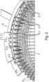
- FIG. 1 A schematically illustrated embodiment of a coil is shown from the axial direction.
- the coil has a coil body (1), which is preferably formed from layered sheets.
- a plurality of axially extending grooves are provided in the coil body (1), in which the conductor sections of the hairpins (2) are arranged in several radially layered layers (3; 3.1; 3.2).
- six layers (3; 3.1; 3.2) of hairpins (2) are provided, although another even number of layers (3; 3.1; 3.2) is also possible.
- An even number of layers (3; 3.1; 3.2) is always provided, since hairpins (2) are generally electrically connected to one another within a double layer.
- the partial coils formed from interconnected hairpins (2) pass through several double layers, these each have transfer contacts between each other.
- the partial coils often pass through the layers (3; 3.1; 3.2) several times in a radial direction, for example from one outer layer (3.1; 3.2) to the other outer layer (3.1; 3.2) and back. In these cases, the hairpins (2) of the opposing strands must be connected in the outer double layer.
- part of the contact areas (2.1) of the hairpins (2) of the corresponding outer layer (3.1; 3.2) are brought into an additional layer (4; 4.1; 4.2).
- Fig. 1 The position of a possible additional layer (4; 4.1; 4.2) is shown with hatched annular areas.
- a radially inner additional layer (4.1) would accordingly accommodate part of the contact area (2.1) originally in the radially inner outer layer (3.1), or contact areas (2.1) of a radially outer layer (3.2) would be accommodated in a radially outer additional layer (4.2).
- the contact areas (2.1) in the additional layer (4; 4.1; 4.2) are electrically conductively connected, after being formed in the circumferential direction, to contact areas of the hairpins (2) of the corresponding outer layer (3.1; 3.2), which have also been formed in the circumferential direction.
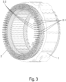
- Fig. 2 shows a perspective view of a portion of a coil in one exemplary embodiment.
- six layers (3; 3.1; 3.2) of hairpins (2) are also provided in the grooves of the coil body (1).
- An additional layer (4.1) is provided adjacent to the radially inner layer (3.1). Some of the contact areas (2.1) are formed from the outer layer (3.1) into the additional layer (4.1).
- the contact areas (2.1) in the additional layer (4.1) are, like the contact areas of the other layers (3; 3.1; 3.2), formed in the circumferential direction in order to be able to Contact areas are combined into contact pairs.
- the direction of the circumferential deformation is opposite to the direction of the outer layer (3.1), thereby achieving a winding step.
- radial rows of formed contact areas are created with a number of contact areas that differs from the number of layers.
- the contact areas (2.2) for connection to an interconnection (5) are provided.
- the contact areas (2.2) of the partial coils are connected to each other and to power electronics via the interconnection (5).
- the additional layer (4.2) is arranged adjacent to the radially outer layer (3.2).
- the contact areas (2.1) formed in the additional layer (4.2) thus extend along an outer circumferential surface.
- the contact areas (2.2) are designed for connection to a Fig. 3 not shown interconnection (5) is provided on the radially inner layer (3.1).
- FIG. 3 The embodiment shown is largely analogous to the one in Fig. 2 shown, which is why reference is made to the description above.
- the additional layer (4.1; 4.2) can, contrary to the illustrated embodiments, also be provided on both radial sides, as for example in Fig. 1 indicated.
Landscapes
- Engineering & Computer Science (AREA)
- Power Engineering (AREA)
- Manufacturing & Machinery (AREA)
- Windings For Motors And Generators (AREA)
- Manufacture Of Motors, Generators (AREA)
Claims (10)
- Bobine comprenant un enroulement distribué, formé d'une pluralité d'épingles à cheveux (2),les épingles à cheveux (2) possédant respectivement deux portions de conducteur droites, lesquelles sont disposées dans des rainures différentes d'un corps de bobine (1), des zones de contact (2.1), qui sont façonnées dans la direction circonférentielle, se raccordant aux portions de conducteur au niveau d'une extrémité axiale, et les portions de conducteur étant connectées à l'autre extrémité axiale par une zone de retournement,un nombre pair de portions de conducteur étant respectivement prévu dans les rainures du corps de bobine (1) en couches (3 ; 3.1 ; 3.2) dans la direction radiale, les zones de contact (2.1) possédant, au niveau de leur extrémité opposée au corps de bobine (1), une portion de connexion, et les portions de connexion étant orientées en rangées qui suivent un tracé radial,les zones de contact (2.1) d'une couche (3 ; 3.1 ; 3.2) étant façonnées dans une même direction circonférentielle,caractérisée en ce qu'une partie des zones de contact (2.1) d'une couche extérieure (3.1 ; 3.2) sont façonnées dans la direction radiale afin de former une couche supplémentaire (4 ; 4.1 ; 4.2), moyennant quoi les zones de contact (2.1) sont disposées dans les rainures en plus de couches que les portions de conducteur, et ces zones de contact (2.1) sont façonnées dans une direction circonférentielle opposée à l'une des zones de contact (2.1) de la couche extérieure (3.1 ; 3.2), moyennant quoi que les zones de contact (2.1) de la couche supplémentaire (4 ; 4.1 ; 4.2) sont disposées dans une même rangée avec les zones de contact (2.1) de la couche extérieure (3.1 ; 3.2) pour une connexion directe avec celles-ci.
- Bobine selon la revendication 1, caractérisée en ce qu'au niveau des deux couches extérieures (3.1 ; 3.2), une partie des zones de contact (2.1) sont déformées dans la direction radiale et forment une couche supplémentaire (4 ; 4.1 ; 4.2).
- Bobine selon la revendication 1 ou 2, caractérisée en ce que du fait des zones de contact (2.1) dans la couche supplémentaire (4 ; 4.1 ; 4.2), une partie des rangées présente un nombre impair de couches, et en ce que dans ces rangées, les zones de contact (2.1) sont prévues pour la connexion à un circuit et les extrémités de contact supplémentaires sont reliées de manière électriquement conductrice à des paires de contacts par leurs portions de connexion.
- Bobine selon l'une des revendications précédentes, caractérisée en ce que la bobine est constituée de plusieurs brins partiels, tels que des phases différentes et/ou des brins parallèles, et en ce qu'une zone de contact (2.1) est disposée dans la couche supplémentaire pour chaque brin partiel.
- Bobine selon l'une des revendications précédentes, caractérisée en ce que les zones de contact (2.1) de la couche supplémentaire (4 ; 4.1 ; 4.2) sont façonnées d'un pas identique à celui des zones de contact (2.1) supplémentaires.
- Bobine selon l'une des revendications 1 à 4, caractérisée en ce que les zones de contact (2.1) de la couche supplémentaire (4 ; 4.1 ; 4.2) sont façonnées d'un pas différent de celui des zones de contact (2.1) supplémentaires.
- Machine électrique, caractérisée en ce qu'une bobine de la machine électrique est prévue conformément à l'une des revendications 1 à 6.
- Procédé de fabrication d'une bobine selon l'une des revendications 1 à 6, comprenant les étapes suivantes :a) insertion des épingles à cheveux (2) dans le corps de bobine (1), les zones de contact (2.1) étant alignées avec les portions de conducteur ;b) façonnage d'une partie des zones de contact (2.1) d'une couche extérieure (3.1 ; 3.2) dans la direction radiale afin de les disposer dans une couche supplémentaire (4 ; 4.1 ; 4.2) ;c) façonnage des zones de contact (2.1) des couches (3 ; 3.1 ; 3.2) dans la direction circonférentielle, les zones de connexion étant disposées en rangées qui suivent un tracé radial.
- Procédé selon la revendication 8, caractérisé en ce que les étapes b) et c) sont effectuées simultanément.
- Procédé selon la revendication 8 ou 9, caractérisé en ce que, dans une étape suivante d), des portions de connexion de zones de contact (2.1) voisines sont soudées en une rangée de paires de contacts.
Applications Claiming Priority (2)
| Application Number | Priority Date | Filing Date | Title |
|---|---|---|---|
| DE102019213474.2A DE102019213474A1 (de) | 2019-09-05 | 2019-09-05 | Spule mit Hairpinwicklung sowie Verfahren zu deren Herstellung |
| PCT/EP2020/073840 WO2021043645A1 (fr) | 2019-09-05 | 2020-08-26 | Bobine à enroulement en épingle à cheveux et procédé de fabrication de ladite bobine |
Publications (3)
| Publication Number | Publication Date |
|---|---|
| EP4026232A1 EP4026232A1 (fr) | 2022-07-13 |
| EP4026232B1 true EP4026232B1 (fr) | 2025-06-25 |
| EP4026232C0 EP4026232C0 (fr) | 2025-06-25 |
Family
ID=72243141
Family Applications (1)
| Application Number | Title | Priority Date | Filing Date |
|---|---|---|---|
| EP20761829.9A Active EP4026232B1 (fr) | 2019-09-05 | 2020-08-26 | Bobine avec bobinage en épingle et procédé pour sa fabrication |
Country Status (5)
| Country | Link |
|---|---|
| US (1) | US11990803B2 (fr) |
| EP (1) | EP4026232B1 (fr) |
| CN (1) | CN114365392B (fr) |
| DE (1) | DE102019213474A1 (fr) |
| WO (1) | WO2021043645A1 (fr) |
Families Citing this family (1)
| Publication number | Priority date | Publication date | Assignee | Title |
|---|---|---|---|---|
| DE102022208027A1 (de) * | 2022-08-03 | 2024-02-08 | Zf Friedrichshafen Ag | Wicklung, Komponente für eine elektrische Maschine und Verfahren zum Herstellen einer Wicklung |
Family Cites Families (15)
| Publication number | Priority date | Publication date | Assignee | Title |
|---|---|---|---|---|
| DE69704773T2 (de) * | 1997-03-10 | 2002-02-21 | Denso Corp., Kariya | Wechselstromgenerator für kraftfahrzeuge |
| JP3740421B2 (ja) * | 2002-01-10 | 2006-02-01 | 株式会社日立製作所 | 回転電機と固定子導線の接続方法 |
| JP3786059B2 (ja) * | 2002-06-25 | 2006-06-14 | 株式会社デンソー | 回転電機のセグメント順次接合ステータコイルおよびその製造方法 |
| DE10260314A1 (de) * | 2002-12-20 | 2004-09-02 | Siemens Ag | Wickelkopfkühlung von elektrischen Maschinen |
| JP2009011116A (ja) * | 2007-06-29 | 2009-01-15 | Hitachi Ltd | 渡り導体部がクランク形状の波巻きコイルを備えた回転電機、分布巻固定子並びにそれらの成形方法及び成形装置 |
| KR101128995B1 (ko) * | 2008-07-14 | 2012-03-27 | 아이신에이더블류 가부시키가이샤 | 스테이터 및 그 제조방법 |
| CN102668332B (zh) * | 2010-06-11 | 2015-04-08 | 丰田自动车株式会社 | 定子以及用于定子的单位线圈的制造方法 |
| US8671559B2 (en) * | 2011-04-27 | 2014-03-18 | GM Global Technology Operations LLC | System for joining stator wires |
| DE112014003897B4 (de) * | 2013-08-26 | 2024-01-18 | Mitsubishi Electric Corporation | Elektrische Rotationsmaschine |
| DE102017201533B4 (de) * | 2017-01-31 | 2023-05-25 | Zf Friedrichshafen Ag | Stator für eine elektrische Maschine |
| CN109586464B (zh) | 2017-09-29 | 2021-11-12 | 比亚迪股份有限公司 | 定子组件、电机和车辆 |
| CN109586450B (zh) * | 2017-09-29 | 2022-01-07 | 比亚迪股份有限公司 | 定子组件和具有其的电机和车辆 |
| CN109586452B (zh) * | 2017-09-29 | 2021-08-10 | 比亚迪股份有限公司 | 定子组件和具有其的电机和车辆 |
| US10965178B2 (en) * | 2018-11-28 | 2021-03-30 | Ford Global Technologies, Llc | Hairpin winding electric machine |
| CN109546779B (zh) * | 2019-01-17 | 2024-04-02 | 博格华纳动力驱动系统(天津)有限公司 | 一种电机绕组及电机定子 |
-
2019
- 2019-09-05 DE DE102019213474.2A patent/DE102019213474A1/de active Pending
-
2020
- 2020-08-26 US US17/640,398 patent/US11990803B2/en active Active
- 2020-08-26 EP EP20761829.9A patent/EP4026232B1/fr active Active
- 2020-08-26 WO PCT/EP2020/073840 patent/WO2021043645A1/fr not_active Ceased
- 2020-08-26 CN CN202080062197.5A patent/CN114365392B/zh active Active
Also Published As
| Publication number | Publication date |
|---|---|
| EP4026232A1 (fr) | 2022-07-13 |
| US20220385155A1 (en) | 2022-12-01 |
| CN114365392A (zh) | 2022-04-15 |
| EP4026232C0 (fr) | 2025-06-25 |
| WO2021043645A1 (fr) | 2021-03-11 |
| US11990803B2 (en) | 2024-05-21 |
| DE102019213474A1 (de) | 2021-03-11 |
| CN114365392B (zh) | 2025-11-25 |
Similar Documents
| Publication | Publication Date | Title |
|---|---|---|
| EP2013961B1 (fr) | Procédé de fabrication d'un enroulement à cage d'écureuil pour le stator d'un moteur électrique | |
| EP3878078B1 (fr) | Machine électrique, véhicule à moteur et procédé pour réaliser un bobinage pour une machine electrique | |
| DE102015217922A1 (de) | Verfahren und zweiteilige Werkzeuganordnung zum Herstellen eines Stators für eine elektrische Maschine | |
| DE102020103165A1 (de) | Stator für eine elektrische Maschine mit bandförmiger Wicklungseinheit für eine Statorwicklung und Verfahren zu dessen Herstellung | |
| DE102013215178A1 (de) | Elektrische Maschine mit einfach oder doppelt geformter Windungsanordnung und Verfahren | |
| DE112012001747T5 (de) | Stromanschlussschiene für die Verwendung in einem Elektromotor | |
| EP2642636A1 (fr) | Enroulement cylindrique creux non ferreux | |
| EP3534498B1 (fr) | Procédé et dispositif de fabrication d'un stator doté d'un enroulement à bobines à air réduites | |
| DE102019211713A1 (de) | Twistvorrichtung sowie Verfahren für eine Hairpin-Wicklung | |
| DE102016222818A1 (de) | Wellenwicklungsspule für ein Statorblechpaket einer elektrischen Maschine | |
| DE102019215094A1 (de) | Wickelschema für eine elektrische Maschine | |
| WO2021063822A1 (fr) | Élément de bobine pour machine électrique | |
| WO2017050566A1 (fr) | Stator | |
| DE102018206003A1 (de) | Vorrichtung und Verfahren zur Ausrichtung einer Hairpinwicklung | |
| DE102018221562A1 (de) | Biegevorrichtung für eine Biegeumformung von Kupferstäben | |
| EP4026232B1 (fr) | Bobine avec bobinage en épingle et procédé pour sa fabrication | |
| EP2436106B1 (fr) | Procédé de fabrication d'un enroulement statorique d'une machine électrique, en particulier d'un générateur de courant alternatif | |
| AT522206B1 (de) | Verfahren zum Bereitstellen von Formstäben aus einem elektrischen Leiterdraht sowie entsprechende Formstäbe | |
| WO2021259753A1 (fr) | Enroulement distribué | |
| EP3167540B1 (fr) | Procédé de fabrication d'une machine électrique comportant des bobines formées et machine électrique et outil de fabrication | |
| DE102020114128B4 (de) | Verschaltungsanordnung einer Wellenwicklung eines Stators einer elektrischen Maschine | |
| DE102019220173A1 (de) | Verfahren zum Biegeverdrehen von Kupferstäben | |
| EP3429063A1 (fr) | Enroulement monocouche de support pour des machines électriques | |
| DE102020212358A1 (de) | Verfahren zur Herstellung eines geschrägten Stators | |
| DE102023201977A1 (de) | Stator mit Hairpin-oder I-Pin-Wicklung und radial verformten Anschlusspins |
Legal Events
| Date | Code | Title | Description |
|---|---|---|---|
| STAA | Information on the status of an ep patent application or granted ep patent |
Free format text: STATUS: UNKNOWN |
|
| STAA | Information on the status of an ep patent application or granted ep patent |
Free format text: STATUS: THE INTERNATIONAL PUBLICATION HAS BEEN MADE |
|
| PUAI | Public reference made under article 153(3) epc to a published international application that has entered the european phase |
Free format text: ORIGINAL CODE: 0009012 |
|
| STAA | Information on the status of an ep patent application or granted ep patent |
Free format text: STATUS: REQUEST FOR EXAMINATION WAS MADE |
|
| 17P | Request for examination filed |
Effective date: 20220303 |
|
| AK | Designated contracting states |
Kind code of ref document: A1 Designated state(s): AL AT BE BG CH CY CZ DE DK EE ES FI FR GB GR HR HU IE IS IT LI LT LU LV MC MK MT NL NO PL PT RO RS SE SI SK SM TR |
|
| DAV | Request for validation of the european patent (deleted) | ||
| DAX | Request for extension of the european patent (deleted) | ||
| GRAP | Despatch of communication of intention to grant a patent |
Free format text: ORIGINAL CODE: EPIDOSNIGR1 |
|
| STAA | Information on the status of an ep patent application or granted ep patent |
Free format text: STATUS: GRANT OF PATENT IS INTENDED |
|
| INTG | Intention to grant announced |
Effective date: 20250128 |
|
| GRAS | Grant fee paid |
Free format text: ORIGINAL CODE: EPIDOSNIGR3 |
|
| GRAA | (expected) grant |
Free format text: ORIGINAL CODE: 0009210 |
|
| STAA | Information on the status of an ep patent application or granted ep patent |
Free format text: STATUS: THE PATENT HAS BEEN GRANTED |
|
| AK | Designated contracting states |
Kind code of ref document: B1 Designated state(s): AL AT BE BG CH CY CZ DE DK EE ES FI FR GB GR HR HU IE IS IT LI LT LU LV MC MK MT NL NO PL PT RO RS SE SI SK SM TR |
|
| REG | Reference to a national code |
Ref country code: GB Ref legal event code: FG4D Free format text: NOT ENGLISH |
|
| REG | Reference to a national code |
Ref country code: CH Ref legal event code: EP |
|
| REG | Reference to a national code |
Ref country code: CH Ref legal event code: EP |
|
| REG | Reference to a national code |
Ref country code: IE Ref legal event code: FG4D Free format text: LANGUAGE OF EP DOCUMENT: GERMAN |
|
| U01 | Request for unitary effect filed |
Effective date: 20250625 |
|
| U07 | Unitary effect registered |
Designated state(s): AT BE BG DE DK EE FI FR IT LT LU LV MT NL PT RO SE SI Effective date: 20250701 |
|
| U20 | Renewal fee for the european patent with unitary effect paid |
Year of fee payment: 6 Effective date: 20250709 |
|
| PG25 | Lapsed in a contracting state [announced via postgrant information from national office to epo] |
Ref country code: NO Free format text: LAPSE BECAUSE OF FAILURE TO SUBMIT A TRANSLATION OF THE DESCRIPTION OR TO PAY THE FEE WITHIN THE PRESCRIBED TIME-LIMIT Effective date: 20250925 Ref country code: GR Free format text: LAPSE BECAUSE OF FAILURE TO SUBMIT A TRANSLATION OF THE DESCRIPTION OR TO PAY THE FEE WITHIN THE PRESCRIBED TIME-LIMIT Effective date: 20250926 |
|
| PG25 | Lapsed in a contracting state [announced via postgrant information from national office to epo] |
Ref country code: HR Free format text: LAPSE BECAUSE OF FAILURE TO SUBMIT A TRANSLATION OF THE DESCRIPTION OR TO PAY THE FEE WITHIN THE PRESCRIBED TIME-LIMIT Effective date: 20250625 |
|
| PG25 | Lapsed in a contracting state [announced via postgrant information from national office to epo] |
Ref country code: RS Free format text: LAPSE BECAUSE OF FAILURE TO SUBMIT A TRANSLATION OF THE DESCRIPTION OR TO PAY THE FEE WITHIN THE PRESCRIBED TIME-LIMIT Effective date: 20250925 |
|
| PG25 | Lapsed in a contracting state [announced via postgrant information from national office to epo] |
Ref country code: IS Free format text: LAPSE BECAUSE OF FAILURE TO SUBMIT A TRANSLATION OF THE DESCRIPTION OR TO PAY THE FEE WITHIN THE PRESCRIBED TIME-LIMIT Effective date: 20251025 |
|
| PG25 | Lapsed in a contracting state [announced via postgrant information from national office to epo] |
Ref country code: SM Free format text: LAPSE BECAUSE OF FAILURE TO SUBMIT A TRANSLATION OF THE DESCRIPTION OR TO PAY THE FEE WITHIN THE PRESCRIBED TIME-LIMIT Effective date: 20250625 |
|
| PG25 | Lapsed in a contracting state [announced via postgrant information from national office to epo] |
Ref country code: CZ Free format text: LAPSE BECAUSE OF FAILURE TO SUBMIT A TRANSLATION OF THE DESCRIPTION OR TO PAY THE FEE WITHIN THE PRESCRIBED TIME-LIMIT Effective date: 20250625 |
|
| PG25 | Lapsed in a contracting state [announced via postgrant information from national office to epo] |
Ref country code: PL Free format text: LAPSE BECAUSE OF FAILURE TO SUBMIT A TRANSLATION OF THE DESCRIPTION OR TO PAY THE FEE WITHIN THE PRESCRIBED TIME-LIMIT Effective date: 20250625 |
|
| PG25 | Lapsed in a contracting state [announced via postgrant information from national office to epo] |
Ref country code: SK Free format text: LAPSE BECAUSE OF FAILURE TO SUBMIT A TRANSLATION OF THE DESCRIPTION OR TO PAY THE FEE WITHIN THE PRESCRIBED TIME-LIMIT Effective date: 20250625 |
|
| PG25 | Lapsed in a contracting state [announced via postgrant information from national office to epo] |
Ref country code: ES Free format text: LAPSE BECAUSE OF FAILURE TO SUBMIT A TRANSLATION OF THE DESCRIPTION OR TO PAY THE FEE WITHIN THE PRESCRIBED TIME-LIMIT Effective date: 20250625 |
|
| REG | Reference to a national code |
Ref country code: CH Ref legal event code: H13 Free format text: ST27 STATUS EVENT CODE: U-0-0-H10-H13 (AS PROVIDED BY THE NATIONAL OFFICE) Effective date: 20260324 |
|
| PG25 | Lapsed in a contracting state [announced via postgrant information from national office to epo] |
Ref country code: MC Free format text: LAPSE BECAUSE OF FAILURE TO SUBMIT A TRANSLATION OF THE DESCRIPTION OR TO PAY THE FEE WITHIN THE PRESCRIBED TIME-LIMIT Effective date: 20250625 |