EP4025842B1 - Warmwasserbereiter und verfahren zum steuern eines warmwasserbereiters - Google Patents
Warmwasserbereiter und verfahren zum steuern eines warmwasserbereiters Download PDFInfo
- Publication number
- EP4025842B1 EP4025842B1 EP20768329.3A EP20768329A EP4025842B1 EP 4025842 B1 EP4025842 B1 EP 4025842B1 EP 20768329 A EP20768329 A EP 20768329A EP 4025842 B1 EP4025842 B1 EP 4025842B1
- Authority
- EP
- European Patent Office
- Prior art keywords
- water heater
- resistance
- heating
- control device
- measuring
- Prior art date
- Legal status (The legal status is an assumption and is not a legal conclusion. Google has not performed a legal analysis and makes no representation as to the accuracy of the status listed.)
- Active
Links
Images



Classifications
-
- F—MECHANICAL ENGINEERING; LIGHTING; HEATING; WEAPONS; BLASTING
- F24—HEATING; RANGES; VENTILATING
- F24H—FLUID HEATERS, e.g. WATER OR AIR HEATERS, HAVING HEAT-GENERATING MEANS, e.g. HEAT PUMPS, IN GENERAL
- F24H1/00—Water heaters, e.g. boilers, continuous-flow heaters or water-storage heaters
- F24H1/10—Continuous-flow heaters, i.e. heaters in which heat is generated only while the water is flowing, e.g. with direct contact of the water with the heating medium
- F24H1/101—Continuous-flow heaters, i.e. heaters in which heat is generated only while the water is flowing, e.g. with direct contact of the water with the heating medium using electric energy supply
- F24H1/102—Continuous-flow heaters, i.e. heaters in which heat is generated only while the water is flowing, e.g. with direct contact of the water with the heating medium using electric energy supply with resistance
- F24H1/103—Continuous-flow heaters, i.e. heaters in which heat is generated only while the water is flowing, e.g. with direct contact of the water with the heating medium using electric energy supply with resistance with bare resistances in direct contact with the fluid
-
- F—MECHANICAL ENGINEERING; LIGHTING; HEATING; WEAPONS; BLASTING
- F24—HEATING; RANGES; VENTILATING
- F24H—FLUID HEATERS, e.g. WATER OR AIR HEATERS, HAVING HEAT-GENERATING MEANS, e.g. HEAT PUMPS, IN GENERAL
- F24H9/00—Details
- F24H9/20—Arrangement or mounting of control or safety devices
- F24H9/2007—Arrangement or mounting of control or safety devices for water heaters
- F24H9/2014—Arrangement or mounting of control or safety devices for water heaters using electrical energy supply
-
- F—MECHANICAL ENGINEERING; LIGHTING; HEATING; WEAPONS; BLASTING
- F24—HEATING; RANGES; VENTILATING
- F24H—FLUID HEATERS, e.g. WATER OR AIR HEATERS, HAVING HEAT-GENERATING MEANS, e.g. HEAT PUMPS, IN GENERAL
- F24H15/00—Control of fluid heaters
- F24H15/20—Control of fluid heaters characterised by control inputs
-
- F—MECHANICAL ENGINEERING; LIGHTING; HEATING; WEAPONS; BLASTING
- F24—HEATING; RANGES; VENTILATING
- F24H—FLUID HEATERS, e.g. WATER OR AIR HEATERS, HAVING HEAT-GENERATING MEANS, e.g. HEAT PUMPS, IN GENERAL
- F24H15/00—Control of fluid heaters
- F24H15/30—Control of fluid heaters characterised by control outputs; characterised by the components to be controlled
- F24H15/355—Control of heat-generating means in heaters
- F24H15/37—Control of heat-generating means in heaters of electric heaters
-
- F—MECHANICAL ENGINEERING; LIGHTING; HEATING; WEAPONS; BLASTING
- F24—HEATING; RANGES; VENTILATING
- F24H—FLUID HEATERS, e.g. WATER OR AIR HEATERS, HAVING HEAT-GENERATING MEANS, e.g. HEAT PUMPS, IN GENERAL
- F24H9/00—Details
- F24H9/18—Arrangement or mounting of grates or heating means
- F24H9/1809—Arrangement or mounting of grates or heating means for water heaters
- F24H9/1818—Arrangement or mounting of electric heating means
-
- F—MECHANICAL ENGINEERING; LIGHTING; HEATING; WEAPONS; BLASTING
- F24—HEATING; RANGES; VENTILATING
- F24H—FLUID HEATERS, e.g. WATER OR AIR HEATERS, HAVING HEAT-GENERATING MEANS, e.g. HEAT PUMPS, IN GENERAL
- F24H9/00—Details
- F24H9/20—Arrangement or mounting of control or safety devices
- F24H9/2007—Arrangement or mounting of control or safety devices for water heaters
- F24H9/2014—Arrangement or mounting of control or safety devices for water heaters using electrical energy supply
- F24H9/2028—Continuous-flow heaters
-
- F—MECHANICAL ENGINEERING; LIGHTING; HEATING; WEAPONS; BLASTING
- F24—HEATING; RANGES; VENTILATING
- F24D—DOMESTIC- OR SPACE-HEATING SYSTEMS, e.g. CENTRAL HEATING SYSTEMS; DOMESTIC HOT-WATER SUPPLY SYSTEMS; ELEMENTS OR COMPONENTS THEREFOR
- F24D2220/00—Components of central heating installations excluding heat sources
- F24D2220/04—Sensors
-
- F—MECHANICAL ENGINEERING; LIGHTING; HEATING; WEAPONS; BLASTING
- F24—HEATING; RANGES; VENTILATING
- F24H—FLUID HEATERS, e.g. WATER OR AIR HEATERS, HAVING HEAT-GENERATING MEANS, e.g. HEAT PUMPS, IN GENERAL
- F24H15/00—Control of fluid heaters
- F24H15/10—Control of fluid heaters characterised by the purpose of the control
- F24H15/124—Preventing or detecting electric faults, e.g. electric leakage
-
- F—MECHANICAL ENGINEERING; LIGHTING; HEATING; WEAPONS; BLASTING
- F24—HEATING; RANGES; VENTILATING
- F24H—FLUID HEATERS, e.g. WATER OR AIR HEATERS, HAVING HEAT-GENERATING MEANS, e.g. HEAT PUMPS, IN GENERAL
- F24H15/00—Control of fluid heaters
- F24H15/10—Control of fluid heaters characterised by the purpose of the control
- F24H15/128—Preventing overheating
-
- F—MECHANICAL ENGINEERING; LIGHTING; HEATING; WEAPONS; BLASTING
- F24—HEATING; RANGES; VENTILATING
- F24H—FLUID HEATERS, e.g. WATER OR AIR HEATERS, HAVING HEAT-GENERATING MEANS, e.g. HEAT PUMPS, IN GENERAL
- F24H15/00—Control of fluid heaters
- F24H15/20—Control of fluid heaters characterised by control inputs
- F24H15/212—Temperature of the water
- F24H15/215—Temperature of the water before heating
-
- F—MECHANICAL ENGINEERING; LIGHTING; HEATING; WEAPONS; BLASTING
- F24—HEATING; RANGES; VENTILATING
- F24H—FLUID HEATERS, e.g. WATER OR AIR HEATERS, HAVING HEAT-GENERATING MEANS, e.g. HEAT PUMPS, IN GENERAL
- F24H15/00—Control of fluid heaters
- F24H15/20—Control of fluid heaters characterised by control inputs
- F24H15/212—Temperature of the water
- F24H15/219—Temperature of the water after heating
-
- F—MECHANICAL ENGINEERING; LIGHTING; HEATING; WEAPONS; BLASTING
- F24—HEATING; RANGES; VENTILATING
- F24H—FLUID HEATERS, e.g. WATER OR AIR HEATERS, HAVING HEAT-GENERATING MEANS, e.g. HEAT PUMPS, IN GENERAL
- F24H15/00—Control of fluid heaters
- F24H15/20—Control of fluid heaters characterised by control inputs
- F24H15/238—Flow rate
-
- F—MECHANICAL ENGINEERING; LIGHTING; HEATING; WEAPONS; BLASTING
- F24—HEATING; RANGES; VENTILATING
- F24H—FLUID HEATERS, e.g. WATER OR AIR HEATERS, HAVING HEAT-GENERATING MEANS, e.g. HEAT PUMPS, IN GENERAL
- F24H15/00—Control of fluid heaters
- F24H15/30—Control of fluid heaters characterised by control outputs; characterised by the components to be controlled
- F24H15/305—Control of valves
- F24H15/31—Control of valves of valves having only one inlet port and one outlet port, e.g. flow rate regulating valves
-
- F—MECHANICAL ENGINEERING; LIGHTING; HEATING; WEAPONS; BLASTING
- F24—HEATING; RANGES; VENTILATING
- F24H—FLUID HEATERS, e.g. WATER OR AIR HEATERS, HAVING HEAT-GENERATING MEANS, e.g. HEAT PUMPS, IN GENERAL
- F24H15/00—Control of fluid heaters
- F24H15/30—Control of fluid heaters characterised by control outputs; characterised by the components to be controlled
- F24H15/395—Information to users, e.g. alarms
-
- F—MECHANICAL ENGINEERING; LIGHTING; HEATING; WEAPONS; BLASTING
- F24—HEATING; RANGES; VENTILATING
- F24H—FLUID HEATERS, e.g. WATER OR AIR HEATERS, HAVING HEAT-GENERATING MEANS, e.g. HEAT PUMPS, IN GENERAL
- F24H15/00—Control of fluid heaters
- F24H15/40—Control of fluid heaters characterised by the type of controllers
- F24H15/414—Control of fluid heaters characterised by the type of controllers using electronic processing, e.g. computer-based
Definitions
- the invention relates to an electrical, in particular electronic, water heater and a method for controlling an electrical, in particular electronic, water heater, preferably water heaters with live radiator surfaces in the water. While the invention is described in particular for such instantaneous water heaters, it also applies to other fluid-carrying domestic appliances.
- Water heaters are fluid-carrying domestic appliances such as instantaneous water heaters, which are used, for example, to generate hot water using electrical energy in particular.
- Such an instantaneous water heater comprises one or more electrical heating elements, with the help of which a fluid, typically water, guided through channels in the instantaneous water heater can be heated to a desired, preset temperature depending on the electrical power supplied to the heating elements.
- Instantaneous water heaters provide hot water without standby losses because they only heat water when hot water is needed.
- Modern instantaneous water heaters are equipped with either a bare wire heating element or a metal-coated heating element.
- the potential difference between the bare wire and the water inlet channel or the water outlet channel that are electrically connected to the earth potential leads to corresponding leakage currents during operation of the heating device. Accordingly, leakage paths are provided so that excessive electrical leakage currents are prevented in particular at the water inlet and water outlet connections that are connected to the earth potential.
- the size of these leakage currents depends, among other things, on the conductivity of the water flowing through the channels. Furthermore, with a bare wire heating element system, there is the Danger of overheating of the wire element if air bubbles enter the device with the water.
- the EP 2 840 404 a control device which comprises an evaluation unit set up to determine a hypothetical leakage current value on the basis of the conductivity value and at least one predefined, design-related device parameter and which is adapted to reduce the heating power of the bare wire heating device if the hypothetical leakage current value exceeds a predefined leakage current threshold value.
- determining the hypothetical leakage current value it is possible to precisely determine the leakage current actually flowing to earth as a function of the conductivity value and the device parameter and only to reduce the leakage current actually flowing to earth by reducing the heating power of the bare wire heating device if the predefined leakage current threshold value is exceeded.
- the disadvantage of the known control device is that the controlled variable (leakage current) deviates from the measured variable (conductivity value) and the fact that no measures are taken to prevent damage caused by overheating of the wire element as a result of air bubbles.
- the WO 2014/098943 A1 proposes to arrange an optical sensor in a flow heater with a bare wire element in order to detect the glow of the wire.
- a disadvantage of using an optical sensor is the fact that the costs increase due to the purchase of the optical sensor and the necessary structural changes to known flow heaters. In addition, it is very complex to monitor the entire area of the heating element, which extends over a relatively wide section of pipe, since several optical sensors would have to be used for this.
- DE 10 2014 000536 A1 describes an electric instantaneous water heater comprising two measuring electrodes arranged in a water-carrying channel, a conductivity measuring electronics, a transformer with a primary side and a secondary side.
- the measuring electronics are connected to the primary side and the two measuring electrodes are connected to the secondary side, so that the measuring electronics are galvanically decoupled from the measuring electrodes via the transformer.
- the measuring electronics provide an electrical, primary-side alternating voltage signal on the primary side of the transformer, so that a secondary-side alternating current is generated on the secondary side via the measuring electrodes and through the water depending on the electrical conductivity of the water, the secondary side current on the primary side influences a primary side current and the measuring electronics measures this primary side current to determine the electrical conductivity.
- DE 84 28 975 U1 describes a hot water instantaneous water heater with a housing having a channel through which water flows, in which an insulating tube containing a heating coil through which electric current flows is arranged in a section of this channel and a water shortage safety device is arranged within the housing which can be controlled by a water shortage safety device which can be controlled as a function of the electrical conductivity of the water contained in the flow channel and which controls the heating current of the heating coil and which has a sensor which is arranged within the channel.
- DE 28 03 951 A1 describes an electric instantaneous water heater with at least one bare wire heating element and at least one water-carrying channel. Two electrodes are arranged in the channel, the distance between which forms a resistance section. A direct voltage derived from the mains voltage of the heating element is applied to the electrodes. One electrode is connected to an electronic comparison circuit, which emits a switch-off signal when the resistance value of the resistance section falls below a minimum value.
- WO 2011/082452 A1 describes a heat generator comprising an electric liquid heater that can be operated to receive liquid and heat the liquid by passing an electric current through the liquid, whereby the liquid heats up due to the resistance properties of the liquid.
- the heat generator further comprises a liquid container in a heat exchanger to receive heated liquid from the electric liquid heater and to transfer the heated liquid to a substance via the heat exchanger, the substance to be heated being located in the vicinity of the heat exchanger.
- the invention is therefore based on the object of specifying a water heater with live radiator surfaces in the water and an associated method for controlling it, which at least partially avoids the disadvantages described above.
- a continuous flow heater is to be provided that enables safe operation in such a way that neither the domestic appliance is damaged nor a user is impaired.
- a water heater is proposed with a flow channel that includes a heating section, a heating element, in particular a bare wire heating element, which is arranged in the region of the heating section, a measuring sensor that has two electrodes that are spaced apart from one another and extend into the flow channel and is designed to measure a resistance of a fluid flowing through the flow channel by applying an alternating voltage between the two electrodes that are spaced apart from one another; and an electronic control device for controlling the electric instantaneous water heater, wherein the electronic control device is designed to control a heating power of the heating element depending on the measured resistance, in particular to interrupt the heating power when a threshold value of the resistance is undershot.
- comparison and/or threshold values of the resistance can be predefined in the control device of the instantaneous water heater so that no further calculation is necessary.
- the measured values provided by the measuring sensor, in particular resistance values are already suitable for direct comparison with the comparison value defined in the control device.
- Implementation is possible, for example, using a simple resistance bridge; no processing of the signals is required. In other words, determining the resistance is not necessary; it is sufficient to compare the existing resistance, for example through the resistance bridge, with a pre-programmed threshold value.
- the resistance measurement is particularly easy thanks to the measuring sensor, which has two electrodes. Two electrodes of the measuring sensor are in contact with the fluid in the flow channel, in particular with water. By applying a voltage between them, the resistance in between can be determined directly via the flowing current. Applying an alternating voltage reduces the This prevents material deposits on the electrodes so that safe operation is possible even over the lifetime of the water heater.
- the threshold value can be adjusted using an adjustable potentiometer or an adjustable resistor on the circuit board. This allows different pre- and post-run distances to be mapped and different types of water heaters to be differentiated using the adjustable resistor without the need for further adjustments, for example to the evaluation electronics or control system.
- the threshold value and/or the calculation is entered, adjusted or changed via an update, in particular from a master computer or server/company server via the Internet or with other data transmission devices.
- a local update on the device using a data carrier is another advantageous embodiment for uploading an update to the parameterization of the threshold value and other data to the water heater.
- Even the algorithm of the calculation can be changed with an update.
- the update can alternatively or additionally be carried out via radio transmission, in particular in a local network such as a WLAN, or via short-range radio such as NFC and/or Bluetooth and the like.
- the threshold value can depend on an availability value of energy from power grids, temperatures of water or an environment, the season, the time of day, a tide, a water level of the groundwater or a water level of a sea, river or lake or other general conditions. This advantageously controls or regulates that the water heater receives, determines or calculates a dependent threshold value from these parameters or one of these parameters. This influences the performance of the water heater in particular.
- a threshold range for the threshold value is advantageously specified, with a minimum threshold value and/or a maximum threshold value.
- the threshold value can advantageously not be set above the maximum threshold value and/or the threshold value cannot be set below the minimum threshold value.
- the maximum threshold value and/or the minimum threshold value corresponds to a permissible value, in particular a value approved by a factory, an authority or an approval institute, or advantageously an approved value range.
- the electric water heater is preferably one with live heating surfaces in the water.
- This can be, for example, a bare wire heating element, where contact of the live surface is desired, or a tubular heating element, where defects in the insulation, for example, result in undesirable conductive contact with the water.
- the solution according to the invention enables safe operation of the water heater, since no leakage currents are conducted to the user.
- the solution according to the invention can provide additional safety if a ground connection of the water heater is not connected or is not connected correctly.
- the resistance measurement or a first resistance measurement takes place in particular at the start of a tapping process on the instantaneous water heater, i.e. before the time at which the heating element is supplied with current.
- the heating element is therefore preferably only supplied with current when the other components have been initialized and the resistance measurement has been carried out.
- the water heater is also designed to detect steam or air bubbles in the flow channel, for example by a resistance between the electrodes exceeding a certain threshold value. Even if air occurs in the flow channel, the instantaneous water heater according to the invention can ensure safe operation, for example by interrupting the electrical heating power to the heating element.
- the control device is preferably designed to determine whether the measured resistance (here also referred to as actual value) is below, within or above a predefined setpoint range and to control the heating power of the heating element, preferably bare wire heating element, depending thereon.
- the invention is based in particular on the knowledge that by measuring a resistance and specifying a target value range, within, below or above which a measured resistance can be (i.e. the target value range does not include the value "zero"), both air or bubbles in the line can be detected and a possibly excessive leakage current value can be recognized and the heating output adjusted accordingly. Furthermore, no calculation such as that of a hypothetical leakage current is necessary. With little software and hardware effort, the fault conditions of the domestic technology device described here can thus be determined with a high degree of reliability in order to take appropriate countermeasures such as reducing the heating output or switching off the device in order to protect the user or the device from damage.
- sensors that can determine a value dependent on the electrical resistance are suitable as measuring sensors.
- These include in particular conductivity sensors and other attachments to the water heater, such as heating bolts, temperature sensors, measuring probes, inlet/outlet pipes, cooling pipes, locking/latching clips, pressure sensors, motor valve spindles, throttle screws, separate screws, etc.
- a warning signal can also be sent to a receiving unit depending on the measured resistance.
- the receiving unit is preferably a receiving unit that can be perceived visually or acoustically by a user of the home technology device, such as one or more display devices (displays), one or more lights, one or more buzzers/vibration motors and/or one or more loudspeakers.
- target value range the following ranges, specified here as (specific) resistance values, apply preferably (lower and upper limits are included in the target value range): 200 to 1200 ⁇ cm, preferably 350 to 1000 ⁇ cm, more preferably 450 to 900 ⁇ cm.
- the target value ranges are usually dependent on national specifications, so that target values can also be in the range of 100 to 2000 ⁇ cm, for example.
- the control device which preferably has a microprocessor, has a start-up operating state.
- the heating power is (only) activated (heating enabled) if the actual value is within the setpoint range. In this case, for example, warm water can be drawn off. If the actual value is outside the setpoint range, the heating device remains off and, if necessary, a first warning signal can be sent to a receiving unit. This avoids error states of the type mentioned here.
- the start operating state is activated as soon as the control device receives a hot water request signal (e.g. through a corresponding tap position and/or detection of a flow in the fluid-carrying line).
- a hot water request signal e.g. through a corresponding tap position and/or detection of a flow in the fluid-carrying line.
- the domestic technology device can have a flow sensor.
- the flow state it is also possible for the flow state to be determined based on a tap position, with an open hot water position indicating that fluid is flowing through the fluid-carrying line arranged in the housing.
- the control device has a heating operating state.
- the heating operating state is activated after the heating release has been granted.
- the heating operating state is only ended when the hot water request is terminated, which can be detected, for example, by the flow sensor described above. If one of the errors described in more detail here is present, the heating operating state is terminated before the hot water request is terminated.
- control device has a fault operating state in which the heating power is at least partially and preferably completely reduced if the actual value is outside the setpoint range.
- An error operating state can preferably (only) be reset by ending the hot water request, i.e. closing a tap, for example. This means that the control device switches to the idle state when the hot water request is ended and is ready for a new hot water request.
- the control device is set to the start operating state by receiving a hot water request signal again. The functional sequence mentioned at the beginning is repeated.
- the fault operating state can only be enabled via a manual reset by a user or a technician. This further increases the safety of operation.
- the control device is designed to determine repeatedly, preferably continuously, whether a repeatedly or continuously measured resistance is below, within or above a predefined setpoint range, in particular when the control device is in the heating operating state.
- the term “repeated” refers to at least two, preferably at least four, cycles of detection and/or adjustment that are carried out, whereby, for example, an average value or other processing can be carried out for the signal output of the control device.
- the term “continuous” describes cycles of detection and/or adjustment that are carried out repeatedly at predefined time intervals until the end of the tapping process. The time intervals are preferably arbitrarily short, so that one speaks of a continuous measurement. Preferably, all of the continuous determinations are carried out as at least two, preferably at least four, repeated cycles of detection and/or adjustment. This measure Safe operation of the building services device is guaranteed for the entire duration of the hot water request.
- the water heater according to the invention provides an indicator of dirty or contaminated water due to the specific resistance.
- the preferred at least two, preferably at least four, sequences of measurements relate to the communication between the different software.
- the aim is to avoid EMC influences/interference, communication problems, etc.
- the control device is set up to send a second warning signal to the receiving unit when the determined actual value falls below the predefined target value range and/or a third warning signal when the determined actual value exceeds the predefined target value range and/or a fourth warning signal when the actual value fluctuates within a predefined period of time and above a permissible degree of fluctuation.
- This embodiment is based on the relationship that water with a high salt content has a high conductivity or a low electrical resistance than a corresponding fluid with a lower salt content and air has a relatively low conductivity or a relatively high electrical resistance compared to water.
- the second warning signal therefore indicates that the fluid (especially water) contains too much salt, or that the leakage current may be high.
- a high salt content results in a high conductivity - corresponding to a low resistance, which means that the setpoint is not reached.
- a low salt content results in a low conductivity - corresponding to a high resistance, which means that the setpoint is exceeded.
- an exceedance is therefore indicative of a relatively low conductivity, and the third warning signal therefore indicates the presence of air in the line or the risk of overheating. Fluctuations are indicative of air bubbles in the line system.
- the fourth warning signal indicates this and the associated risk of overheating.
- the predefined, permissible degree of fluctuation e.g. maximum permissible amplitude and/or number of amplitudes within a predefined period of time
- Tests are carried out in which the pipe is flowed through with water that is free of air bubbles and water that contains air bubbles and the actual value is plotted over time.
- the first warning signal, second warning signal, third warning signal and fourth warning signal may be different or identical depending on the desired level of information regarding a possible cause of the error.
- the control device has a manipulation protection.
- the control device is set up to detect a short circuit of the measuring sensor or its cable, a disconnection of the measuring sensor cable, a disconnection of the power supply of the control device and/or a cable break of the measuring sensor or power supply.
- a resistance that is too low can indicate a short circuit and a resistance that is too high can indicate a cable break, a cable that is not connected or has been disconnected.
- the measuring sensor is part of a measuring device which is galvanically isolated from the control device.
- the flow channel has an upstream section, the heating section and a downstream section, with the measuring sensor being arranged in the downstream section.
- a temperature correction i.e. taking into account the temperature dependence of the conductivity
- the measuring sensor can be arranged in the upstream section. This only requires an adjustment of the resistance, for example a resistance bridge on a circuit board.
- the measuring sensor has two electrodes spaced apart from one another. These can be spaced apart from one another along the flow channel, either lengthwise or transversely to the flow channel.
- the electrodes are particularly preferably orthogonal to the flow channel, i.e. perpendicular to the flow direction. This offers particular advantages in terms of pressure loss, especially in small flow channels. At the same time, any influence on the measuring current by the leakage current is avoided.
- the electrodes can be made from all electrically conductive and water-conducting components.
- all components of the electrodes are drinking water compliant. These can in particular be selected from the group consisting of heating bolts, temperature sensors, measuring probes, inlet and/or outlet pipes, cooling pipes, locking clips, locking clips, pressure sensors, engine valve axes, screws and throttle screws.
- the heating element itself is not an electrode of the measuring sensor and, in addition to the heating element, two electrodes are provided for detecting the resistance value.
- stainless steel is particularly worth mentioning due to its ease of procurement, corrosion resistance, resistance to fouling or limescale deposits and organic effects.
- Metal-coated, anodized, chrome-plated and nickel-plated materials such as metals, plastics, non-ferrous metals and sintered materials are also conceivable.
- a measuring section formed by the electrodes runs transversely to the direction of flow.
- the measuring section formed by the electrodes represents the shortest connection within the fluid-carrying line between the electrodes.
- the measuring section preferably runs transversely, in particular orthogonally, to the direction of flow. This can prevent interference currents and minimize influences on the flow and pressure losses. In addition, the measurement is not influenced by the leakage current.
- the measuring device is operated with alternating current, preferably safety extra-low voltage. This avoids undesirable electrolysis effects on the measuring device, in particular on the electrodes. In order to minimize disruptive polarization effects on the measuring device, in particular on the electrodes, it is also preferred that the measuring device is operated in the low-voltage range.
- control device comprises a microprocessor which is configured to digitally process the actual value after analog/digital conversion.
- an electric water heater in particular an electronic instantaneous water heater for hot water preparation, comprising: detecting a resistance of a fluid flowing through a flow channel of the water heater by means of a measuring sensor which has two spaced-apart electrodes extending into the flow channel and is designed to detect a resistance of the fluid by applying an alternating voltage between the two spaced-apart electrodes; and controlling the heating power of the heating element depending on the detected resistance, in particular interrupting the heating power when a threshold value of the resistance is undershot and/or exceeded.
- the method according to the invention therefore does not necessarily require data processing of the detected resistance. Rather, it is sufficient that it is determined for the detected value, for example by means of a resistance bridge, whether the value falls below and/or exceeds a threshold value.
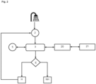
- Fig. 1 shows a domestic appliance 100, in particular an electric instantaneous water heater, with a fluid-carrying line 9, 10, 11, in which a heating element 12 for heating the fluid flowing through the line (9, 10, 11) extends in a line section 9.
- the heating element 12 can be designed as a bare wire heating element or tubular heating element, preferably a bare wire heating element.
- the domestic appliance also comprises a cold water inlet 6 for connection to a water supply line and a hot water outlet 7.
- the hot water connection 7 can be connected to a water tap via a hot water line (not shown).
- the cable has an upstream section 10 and a downstream section 11 before and after the heating element 12. These are unheated channels that serve as resistance sections for the high voltages present at the heating element 12 through which current flows, so that no high leakage current flows at the connections 6, 7. If the connections 6, 7 are connected to a protective conductor as intended, the leakage current flows via the protective conductor.
- the domestic appliance comprises a measuring sensor 21 and an electronic control device 3.
- the measuring sensor 21 is designed to detect an electrical resistance.
- the control device 3 is designed to control a heating output of the heating element 12 taking into account the resistance value and a predefined resistance range.
- a detected resistance value does not have to be further processed, for example digitized, it is sufficient that a setpoint/actual value comparison is carried out, for example using a resistance bridge.
- a warning signal can be sent to a receiving unit.
- the receiving unit can be a control unit 5, a warning and/or control lamp arranged on the domestic appliance and/or a user's mobile device (not shown).
- the measuring sensor 21 is part of a measuring device 20, which is preferably galvanically isolated from the control device 3.
- the aforementioned components are functionally coupled to the control device 3, so that the control device 3, in error-free operation (i.e., provided the measured resistance is within the tolerance range), controls the heating power of the heating element 12 and/or valve position of the valve 1 depending on the flow rate and/or inlet and/or outlet temperature of the fluid and/or a desired (predetermined) hot water temperature.
- a user makes a hot water request to the domestic appliance 100, for example by opening a tap, for example for a shower, water flows through the line 9, 10, 11 of the domestic appliance 100, and the flow sensor 2 registers the hot water requirement.
- the flow sensor 2 sends a hot water requirement signal to the control device 3.
- the control device 3 After receiving the hot water requirement signal, the control device 3 is woken up from the idle state and, after a possible initialization phase, is placed in a start operating state.
- the control device queries the measuring device 20 for the (montane) actual value determined by the measuring sensor 21.
- E the actual value By comparing E the actual value and a predefined setpoint value (actual value-setpoint value comparison), the control device 3 controls the heating output of the heating element 12 as follows. If the actual value is in a predefined setpoint range, the heating enable H is issued. Otherwise, an error state exists and no heating enable NH is issued.
- the measuring device 20 preferably carries out the measurement with a defined measuring voltage (AC). The water resistance and consequently the conductivity of the water can be determined from this.
- AC measuring voltage
- the error state can be displayed on the control unit 5. It is also possible that the error state can be reset by closing the hot water request/tap. In other words, the control device 3 is set up in such a way that it is put into the idle state by closing the tap, which in turn can be determined using the flow sensor 2.
- the domestic technology device 100 is therefore ready for a new hot water request and can be put from the idle state into the start operating state described above by registering a hot water request.
- the heating is enabled by the control device 3 and the domestic technology device 100 begins the heating process - warm water flows.
- the preset target temperature can optionally be displayed in the control unit 5.
- a continuous measurement is preferably carried out via the interacting components (control device 3, measuring device 20, measuring sensor 21) and the function carried out in the start-up operating state is carried out repeatedly.
- the conductivity of the water is continuously monitored by the developed system.
- the setpoint-actual value comparison can be carried out by taking two measurements and calculating the arithmetic mean (normal and inverted values). The arithmetic mean of the actual value is compared with the setpoint range. A binary evaluation according to "within tolerance” or “outside tolerance” is sufficient as a result. The result of the evaluation can be sent by telegram.
- the setpoint range can preferably be parameterized or set via software.
- the setpoint range (and thus the switch-off limits) are implemented in the software at the factory and that it is not possible for a user or service technician to manipulate or change the setpoint range.
- a preferred circuit of the system according to the invention for controlling the domestic appliance 100 is now described.
- the supply voltage and I 2 C data lines from the domestic appliance 100 for determining the actual value (conductance measurement) are implemented via an I2C connection.
- a DCDC converter ensures the isolation of the supply voltage and an I 2 C Iso component ensures the isolation of the data line.
- a 3V3 A linear regulator is provided to decouple the rest of the circuit from the DCDC converter.
- This supplies a microcontroller, the secondary I2C component, two driver stages 30 and an amplifier stage 31.
- the microcontroller generates a 3V3 alternating voltage via the two driver stages 30. This is applied to a resistance divider consisting of series resistor Rv and water resistance Rw.
- the measurement signal is passed to the microcontroller via the amplifier stage 31, where it is evaluated and passed on to the control device 3 via the I 2 C bus.
- Fig. 4 shows a perspective view of a hot water outlet side flange 15 of the domestic technology device 100 with a measuring sensor 21 designed as electrodes 22, 22'.
- Electrically conductive hold-down devices 23 made of sheet metal are attached to the top of the housing of the flange 15 by means of fastening screws 26 and transmit the measuring signal of the measuring sensors 22, 22' via cable lug sleeves 24.
- the measuring sensors 22, 22' are electrically connected to the hold-down device 23 by means of fastening nuts 25 and are fixed in the axial direction of the measuring sensors 22, 22'.
- Fig. 5 shows exemplary arrangements of measuring sensors 21 designed as electrodes 22, 22' in the domestic technology device 100.
- Arrangement A represents a Schuko plug version without a metal retainer.
- the plug 27 protrudes through openings in a component, such as the flange 15, into a fluid-carrying line section, which is preferably arranged in the downstream section 11.
- the plug 27 can be attached to the component by means of screws, clamps or via the clamping force of the plug 27.
- the line 11 can be sealed by means of O-rings on the electrodes 22, 22', a flat seal on each electrode 22, 22' or a large flat seal between the plug 27 and the component (e.g. flange 15).
- Arrangement B shows a similar arrangement based on the principle of a Schuko socket.
- the measuring sensors 21, again designed as electrodes 22, 22' can be permanently attached - for example by overmolding, casting, gluing, welding - in a fluid-carrying component, so that the measuring sensors 22, 22' protrude into the fluid flowing through the line 11.
- An electrical spring connection to the electrodes 22, 22' can be established by means of a plug 27 in order to tap an electrical signal.
- the electrodes 22, 22' are designed as two screws spaced parallel to each other.
- the measuring sensor 21 is designed as two electrodes 22, 22' spaced coaxially from one another.
- Arrangement E shows a top view of two electrodes 22, 22' screwed onto a circuit board as a measuring sensor 21 with conductor tracks for deriving the measuring signal, which can be forwarded by means of a snap-in plug that can be connected to the circuit board.
- the measuring sensor 21 is designed as two electrodes 22, 22' cast into a fluid-carrying component made of plastic.
- Arrangement G shows an arrangement in which the measuring sensor 21 is formed by a screw 22 and an electrically conductive component (e.g. water outlet) 22'.
- an electrically non-conductive component 28 is arranged at the hot water outlet between two electrically conductive line sections serving as electrodes 22, 22'.
- the arrangement can be sealed using flat seals.
Landscapes
- Engineering & Computer Science (AREA)
- Physics & Mathematics (AREA)
- Thermal Sciences (AREA)
- Chemical & Material Sciences (AREA)
- Combustion & Propulsion (AREA)
- Mechanical Engineering (AREA)
- General Engineering & Computer Science (AREA)
- Instantaneous Water Boilers, Portable Hot-Water Supply Apparatuses, And Control Of Portable Hot-Water Supply Apparatuses (AREA)
- Control Of Resistance Heating (AREA)
Applications Claiming Priority (2)
| Application Number | Priority Date | Filing Date | Title |
|---|---|---|---|
| DE102019123760.2A DE102019123760A1 (de) | 2019-09-05 | 2019-09-05 | Warmwasserbereiter und Verfahren zum Steuern eines Warmwasserbereiters |
| PCT/EP2020/074904 WO2021044047A1 (de) | 2019-09-05 | 2020-09-07 | Warmwasserbereiter und verfahren zum steuern eines warmwasserbereiters |
Publications (2)
| Publication Number | Publication Date |
|---|---|
| EP4025842A1 EP4025842A1 (de) | 2022-07-13 |
| EP4025842B1 true EP4025842B1 (de) | 2024-11-06 |
Family
ID=72428282
Family Applications (1)
| Application Number | Title | Priority Date | Filing Date |
|---|---|---|---|
| EP20768329.3A Active EP4025842B1 (de) | 2019-09-05 | 2020-09-07 | Warmwasserbereiter und verfahren zum steuern eines warmwasserbereiters |
Country Status (5)
| Country | Link |
|---|---|
| EP (1) | EP4025842B1 (pl) |
| CN (1) | CN114585864A (pl) |
| DE (1) | DE102019123760A1 (pl) |
| PL (1) | PL4025842T3 (pl) |
| WO (1) | WO2021044047A1 (pl) |
Families Citing this family (5)
| Publication number | Priority date | Publication date | Assignee | Title |
|---|---|---|---|---|
| SK9420Y1 (sk) | 2021-05-07 | 2022-01-26 | Protherm Production S.R.O. | Elektrický prietokový ohrievač a spôsob riadenia elektrického prietokového ohrievača |
| EP4422460B1 (en) * | 2022-12-13 | 2025-02-12 | Versuni Holding B.V. | Coffee brewing apparatus and method of operating the same |
| DE102023102819A1 (de) | 2023-02-06 | 2024-08-08 | Aquis Systems AG | Heißwasserbereiter und Verfahren zur Initialisierung eines Heißwasserbereiters |
| DE102024103547A1 (de) * | 2024-02-08 | 2025-08-14 | Stiebel Eltron Gmbh & Co. Kg | Verfahren zum Steuern mindestens eines elektrischen Warmwasserbereiters |
| DE102024103546A1 (de) * | 2024-02-08 | 2025-08-14 | Stiebel Eltron Gmbh & Co. Kg | Verfahren zum Steuern mindestens eines elektrischen Warmwasserbereiters |
Family Cites Families (6)
| Publication number | Priority date | Publication date | Assignee | Title |
|---|---|---|---|---|
| DE2803951A1 (de) * | 1978-01-30 | 1979-08-02 | Stiebel Eltron Gmbh & Co Kg | Elektrischer durchlauferhitzer mit wenigstens einem blankdrahtheizkoerper |
| DE8428975U1 (de) * | 1984-10-02 | 1985-12-19 | Bernhardt, Werner, 8069 Ilmmünster | Heißwasser-Durchlauferhitzer |
| AU2011204746B2 (en) * | 2010-01-07 | 2013-08-15 | Microheat Technologies Pty Ltd | A heat generator and method of generating heat using electrically energised fluid |
| WO2014098943A1 (en) * | 2012-12-21 | 2014-06-26 | Eemax, Inc. | Next generation bare wire water heater |
| DK2840404T3 (en) * | 2013-08-20 | 2016-06-27 | Gerdes Ohg | Electric blanket water heater and method for controlling the same |
| DE102014000536A1 (de) * | 2014-01-20 | 2015-07-23 | Stiebel Eltron Gmbh & Co. Kg | Verfahren und Vorrichtung zum Erfassen einer elektrischen Leitfähigkeit in einem Durchlauferhitzer |
-
2019
- 2019-09-05 DE DE102019123760.2A patent/DE102019123760A1/de active Pending
-
2020
- 2020-09-07 WO PCT/EP2020/074904 patent/WO2021044047A1/de not_active Ceased
- 2020-09-07 EP EP20768329.3A patent/EP4025842B1/de active Active
- 2020-09-07 CN CN202080063145.XA patent/CN114585864A/zh active Pending
- 2020-09-07 PL PL20768329.3T patent/PL4025842T3/pl unknown
Also Published As
| Publication number | Publication date |
|---|---|
| WO2021044047A1 (de) | 2021-03-11 |
| CN114585864A (zh) | 2022-06-03 |
| PL4025842T3 (pl) | 2025-03-24 |
| EP4025842A1 (de) | 2022-07-13 |
| DE102019123760A1 (de) | 2021-03-11 |
Similar Documents
| Publication | Publication Date | Title |
|---|---|---|
| EP4025842A1 (de) | Warmwasserbereiter und verfahren zum steuern eines warmwasserbereiters | |
| DE69633933T2 (de) | Flüssigkeitserhitzer mit verbesserter kontrolle des heizelements | |
| DE102016013052A1 (de) | Durchlauferhitzer und Verfahren zur Steuerung eines Durchlauferhitzers | |
| EP3217157B1 (de) | Heizkostenverteiler und verfahren zur erfassung der durch einen heizkörper abgegebenen wärmemenge | |
| DE102011085082B3 (de) | Verfahren und Schaltungsanordnung zur Ermittlung der Temperatur eines Kraftstoffeinspritzventils und Verfahren zur Regelung der Temperatur eines Kraftstoffeinspritzventils | |
| DE102019004320A1 (de) | Durchlauferhitzer und diesen umfassender elektronischer dezentraler Wassererhitzer | |
| EP2659199B1 (de) | Durchlauferhitzer | |
| DE102014000536A1 (de) | Verfahren und Vorrichtung zum Erfassen einer elektrischen Leitfähigkeit in einem Durchlauferhitzer | |
| DE202012104942U1 (de) | Ventil für Warmwasseranlagen | |
| DE102021120396A1 (de) | Leitungsanordnung mit dezentraler Trinkwassererwärmung und Verfahren zum Betrieb einer Leitungsanordnung | |
| AT512141B1 (de) | Ventil für warmwasseranlagen | |
| DE69919646T2 (de) | Steuerung und Überwachung der Sicherheit einer Flüssigkeitsheizanlage, worin die elektrischen Heizelemente als Sensor gebraucht werden | |
| DE102004019533B4 (de) | Verfahren zum Ein- und Ausschalten einer Zirkulationspumpe | |
| DE102004055850A1 (de) | Wassererhitzer, Durchlauferhitzer und Verfahren | |
| DE102004055261B3 (de) | Schutzeinrichtung für einen Warmwasserspeicher | |
| WO2017085016A1 (de) | Schaltung einer pumpe in abhängigkeit des durchsatzes, wobei der durchsatz durch einen thermischen durchflussmesser bestimmt wird | |
| DE102014010517B4 (de) | Haustechnikgerät, insbesondere Durchlauferhitzer | |
| DE202007011607U1 (de) | Wohnungsversorgungsstation | |
| DE102018001313A1 (de) | Wasserbereitstellungsvorrichtung zur Bereitstellung von Wasser einstellbarer Temperatur, System zur Wasserbereitstellung sowie Verfahren zum Betreiben einer Wasserbereitstellungsvorrichtung | |
| EP4086533B1 (en) | Instantaneous electric water heater and method of controlling the instantaneous electric water heater | |
| AT514706A4 (de) | Positionsüberwachung eines Sensors | |
| DE102013020635B4 (de) | Warmwassergerät und Verfahren zum Betreiben eines Warmwassergerätes | |
| DE3705565A1 (de) | Verfahren zur ueberwachung des rohrsystems einer warmwasser-heizungsanlage | |
| EP2463593A1 (de) | Verfahren zum Betrieb einer Heizungsanlage | |
| DE3871701T2 (de) | Gaskesselregulierungseinrichtung. |
Legal Events
| Date | Code | Title | Description |
|---|---|---|---|
| STAA | Information on the status of an ep patent application or granted ep patent |
Free format text: STATUS: UNKNOWN |
|
| STAA | Information on the status of an ep patent application or granted ep patent |
Free format text: STATUS: THE INTERNATIONAL PUBLICATION HAS BEEN MADE |
|
| PUAI | Public reference made under article 153(3) epc to a published international application that has entered the european phase |
Free format text: ORIGINAL CODE: 0009012 |
|
| STAA | Information on the status of an ep patent application or granted ep patent |
Free format text: STATUS: REQUEST FOR EXAMINATION WAS MADE |
|
| 17P | Request for examination filed |
Effective date: 20220331 |
|
| AK | Designated contracting states |
Kind code of ref document: A1 Designated state(s): AL AT BE BG CH CY CZ DE DK EE ES FI FR GB GR HR HU IE IS IT LI LT LU LV MC MK MT NL NO PL PT RO RS SE SI SK SM TR |
|
| DAV | Request for validation of the european patent (deleted) | ||
| DAX | Request for extension of the european patent (deleted) | ||
| P01 | Opt-out of the competence of the unified patent court (upc) registered |
Effective date: 20230524 |
|
| GRAP | Despatch of communication of intention to grant a patent |
Free format text: ORIGINAL CODE: EPIDOSNIGR1 |
|
| STAA | Information on the status of an ep patent application or granted ep patent |
Free format text: STATUS: GRANT OF PATENT IS INTENDED |
|
| RIC1 | Information provided on ipc code assigned before grant |
Ipc: F24H 15/37 20220101ALI20240312BHEP Ipc: F24H 15/20 20220101ALI20240312BHEP Ipc: F24H 9/20 20060101ALI20240312BHEP Ipc: F24H 1/10 20060101AFI20240312BHEP |
|
| INTG | Intention to grant announced |
Effective date: 20240409 |
|
| GRAS | Grant fee paid |
Free format text: ORIGINAL CODE: EPIDOSNIGR3 |
|
| GRAA | (expected) grant |
Free format text: ORIGINAL CODE: 0009210 |
|
| STAA | Information on the status of an ep patent application or granted ep patent |
Free format text: STATUS: THE PATENT HAS BEEN GRANTED |
|
| AK | Designated contracting states |
Kind code of ref document: B1 Designated state(s): AL AT BE BG CH CY CZ DE DK EE ES FI FR GB GR HR HU IE IS IT LI LT LU LV MC MK MT NL NO PL PT RO RS SE SI SK SM TR |
|
| REG | Reference to a national code |
Ref country code: GB Ref legal event code: FG4D Free format text: NOT ENGLISH |
|
| REG | Reference to a national code |
Ref country code: CH Ref legal event code: EP |
|
| REG | Reference to a national code |
Ref country code: DE Ref legal event code: R096 Ref document number: 502020009704 Country of ref document: DE |
|
| REG | Reference to a national code |
Ref country code: IE Ref legal event code: FG4D Free format text: LANGUAGE OF EP DOCUMENT: GERMAN |
|
| REG | Reference to a national code |
Ref country code: LT Ref legal event code: MG9D |
|
| REG | Reference to a national code |
Ref country code: NL Ref legal event code: MP Effective date: 20241106 |
|
| PG25 | Lapsed in a contracting state [announced via postgrant information from national office to epo] |
Ref country code: PT Free format text: LAPSE BECAUSE OF FAILURE TO SUBMIT A TRANSLATION OF THE DESCRIPTION OR TO PAY THE FEE WITHIN THE PRESCRIBED TIME-LIMIT Effective date: 20250306 Ref country code: IS Free format text: LAPSE BECAUSE OF FAILURE TO SUBMIT A TRANSLATION OF THE DESCRIPTION OR TO PAY THE FEE WITHIN THE PRESCRIBED TIME-LIMIT Effective date: 20250306 Ref country code: HR Free format text: LAPSE BECAUSE OF FAILURE TO SUBMIT A TRANSLATION OF THE DESCRIPTION OR TO PAY THE FEE WITHIN THE PRESCRIBED TIME-LIMIT Effective date: 20241106 |
|
| PG25 | Lapsed in a contracting state [announced via postgrant information from national office to epo] |
Ref country code: FI Free format text: LAPSE BECAUSE OF FAILURE TO SUBMIT A TRANSLATION OF THE DESCRIPTION OR TO PAY THE FEE WITHIN THE PRESCRIBED TIME-LIMIT Effective date: 20241106 Ref country code: NL Free format text: LAPSE BECAUSE OF FAILURE TO SUBMIT A TRANSLATION OF THE DESCRIPTION OR TO PAY THE FEE WITHIN THE PRESCRIBED TIME-LIMIT Effective date: 20241106 |
|
| PG25 | Lapsed in a contracting state [announced via postgrant information from national office to epo] |
Ref country code: BG Free format text: LAPSE BECAUSE OF FAILURE TO SUBMIT A TRANSLATION OF THE DESCRIPTION OR TO PAY THE FEE WITHIN THE PRESCRIBED TIME-LIMIT Effective date: 20241106 |
|
| PG25 | Lapsed in a contracting state [announced via postgrant information from national office to epo] |
Ref country code: ES Free format text: LAPSE BECAUSE OF FAILURE TO SUBMIT A TRANSLATION OF THE DESCRIPTION OR TO PAY THE FEE WITHIN THE PRESCRIBED TIME-LIMIT Effective date: 20241106 |
|
| PG25 | Lapsed in a contracting state [announced via postgrant information from national office to epo] |
Ref country code: NO Free format text: LAPSE BECAUSE OF FAILURE TO SUBMIT A TRANSLATION OF THE DESCRIPTION OR TO PAY THE FEE WITHIN THE PRESCRIBED TIME-LIMIT Effective date: 20250206 |
|
| PG25 | Lapsed in a contracting state [announced via postgrant information from national office to epo] |
Ref country code: GR Free format text: LAPSE BECAUSE OF FAILURE TO SUBMIT A TRANSLATION OF THE DESCRIPTION OR TO PAY THE FEE WITHIN THE PRESCRIBED TIME-LIMIT Effective date: 20250207 Ref country code: LV Free format text: LAPSE BECAUSE OF FAILURE TO SUBMIT A TRANSLATION OF THE DESCRIPTION OR TO PAY THE FEE WITHIN THE PRESCRIBED TIME-LIMIT Effective date: 20241106 |
|
| PG25 | Lapsed in a contracting state [announced via postgrant information from national office to epo] |
Ref country code: RS Free format text: LAPSE BECAUSE OF FAILURE TO SUBMIT A TRANSLATION OF THE DESCRIPTION OR TO PAY THE FEE WITHIN THE PRESCRIBED TIME-LIMIT Effective date: 20250206 |
|
| PG25 | Lapsed in a contracting state [announced via postgrant information from national office to epo] |
Ref country code: SM Free format text: LAPSE BECAUSE OF FAILURE TO SUBMIT A TRANSLATION OF THE DESCRIPTION OR TO PAY THE FEE WITHIN THE PRESCRIBED TIME-LIMIT Effective date: 20241106 |
|
| PG25 | Lapsed in a contracting state [announced via postgrant information from national office to epo] |
Ref country code: DK Free format text: LAPSE BECAUSE OF FAILURE TO SUBMIT A TRANSLATION OF THE DESCRIPTION OR TO PAY THE FEE WITHIN THE PRESCRIBED TIME-LIMIT Effective date: 20241106 |
|
| PG25 | Lapsed in a contracting state [announced via postgrant information from national office to epo] |
Ref country code: EE Free format text: LAPSE BECAUSE OF FAILURE TO SUBMIT A TRANSLATION OF THE DESCRIPTION OR TO PAY THE FEE WITHIN THE PRESCRIBED TIME-LIMIT Effective date: 20241106 |
|
| PG25 | Lapsed in a contracting state [announced via postgrant information from national office to epo] |
Ref country code: RO Free format text: LAPSE BECAUSE OF FAILURE TO SUBMIT A TRANSLATION OF THE DESCRIPTION OR TO PAY THE FEE WITHIN THE PRESCRIBED TIME-LIMIT Effective date: 20241106 |
|
| PG25 | Lapsed in a contracting state [announced via postgrant information from national office to epo] |
Ref country code: SK Free format text: LAPSE BECAUSE OF FAILURE TO SUBMIT A TRANSLATION OF THE DESCRIPTION OR TO PAY THE FEE WITHIN THE PRESCRIBED TIME-LIMIT Effective date: 20241106 |
|
| PG25 | Lapsed in a contracting state [announced via postgrant information from national office to epo] |
Ref country code: CZ Free format text: LAPSE BECAUSE OF FAILURE TO SUBMIT A TRANSLATION OF THE DESCRIPTION OR TO PAY THE FEE WITHIN THE PRESCRIBED TIME-LIMIT Effective date: 20241106 |
|
| PG25 | Lapsed in a contracting state [announced via postgrant information from national office to epo] |
Ref country code: IT Free format text: LAPSE BECAUSE OF FAILURE TO SUBMIT A TRANSLATION OF THE DESCRIPTION OR TO PAY THE FEE WITHIN THE PRESCRIBED TIME-LIMIT Effective date: 20241106 |
|
| REG | Reference to a national code |
Ref country code: DE Ref legal event code: R097 Ref document number: 502020009704 Country of ref document: DE |
|
| PG25 | Lapsed in a contracting state [announced via postgrant information from national office to epo] |
Ref country code: SE Free format text: LAPSE BECAUSE OF FAILURE TO SUBMIT A TRANSLATION OF THE DESCRIPTION OR TO PAY THE FEE WITHIN THE PRESCRIBED TIME-LIMIT Effective date: 20241106 |
|
| PLBE | No opposition filed within time limit |
Free format text: ORIGINAL CODE: 0009261 |
|
| STAA | Information on the status of an ep patent application or granted ep patent |
Free format text: STATUS: NO OPPOSITION FILED WITHIN TIME LIMIT |
|
| PGFP | Annual fee paid to national office [announced via postgrant information from national office to epo] |
Ref country code: DE Payment date: 20250919 Year of fee payment: 6 |
|
| 26N | No opposition filed |
Effective date: 20250807 |
|
| PGFP | Annual fee paid to national office [announced via postgrant information from national office to epo] |
Ref country code: PL Payment date: 20250828 Year of fee payment: 6 |
|
| PGFP | Annual fee paid to national office [announced via postgrant information from national office to epo] |
Ref country code: GB Payment date: 20250919 Year of fee payment: 6 |
|
| REG | Reference to a national code |
Ref country code: CH Ref legal event code: H13 Free format text: ST27 STATUS EVENT CODE: U-0-0-H10-H13 (AS PROVIDED BY THE NATIONAL OFFICE) Effective date: 20260504 |