EP4024973A1 - Procédé par un dispositif utilisateur dans un système de communication sans fil - Google Patents
Procédé par un dispositif utilisateur dans un système de communication sans fil Download PDFInfo
- Publication number
- EP4024973A1 EP4024973A1 EP20858701.4A EP20858701A EP4024973A1 EP 4024973 A1 EP4024973 A1 EP 4024973A1 EP 20858701 A EP20858701 A EP 20858701A EP 4024973 A1 EP4024973 A1 EP 4024973A1
- Authority
- EP
- European Patent Office
- Prior art keywords
- information
- positioning
- prs
- ans
- prss
- Prior art date
- Legal status (The legal status is an assumption and is not a legal conclusion. Google has not performed a legal analysis and makes no representation as to the accuracy of the status listed.)
- Pending
Links
- 238000000034 method Methods 0.000 title claims abstract description 149
- 238000004891 communication Methods 0.000 title claims abstract description 139
- 230000015654 memory Effects 0.000 claims description 47
- 238000004590 computer program Methods 0.000 claims description 2
- 230000005540 biological transmission Effects 0.000 description 140
- 239000010410 layer Substances 0.000 description 47
- 238000005259 measurement Methods 0.000 description 40
- 230000006870 function Effects 0.000 description 38
- 238000005516 engineering process Methods 0.000 description 27
- 238000013468 resource allocation Methods 0.000 description 25
- 238000010586 diagram Methods 0.000 description 22
- 238000013473 artificial intelligence Methods 0.000 description 21
- 230000008569 process Effects 0.000 description 16
- 238000012545 processing Methods 0.000 description 12
- 238000010295 mobile communication Methods 0.000 description 9
- 238000007726 management method Methods 0.000 description 8
- 239000000969 carrier Substances 0.000 description 7
- 238000013507 mapping Methods 0.000 description 6
- 230000000737 periodic effect Effects 0.000 description 6
- 230000011664 signaling Effects 0.000 description 6
- 239000000470 constituent Substances 0.000 description 5
- 230000000694 effects Effects 0.000 description 5
- 230000004044 response Effects 0.000 description 5
- 230000001133 acceleration Effects 0.000 description 4
- 125000004122 cyclic group Chemical group 0.000 description 4
- 238000005286 illumination Methods 0.000 description 4
- 230000007774 longterm Effects 0.000 description 4
- 238000010187 selection method Methods 0.000 description 4
- 238000012546 transfer Methods 0.000 description 4
- 238000003491 array Methods 0.000 description 3
- 230000003190 augmentative effect Effects 0.000 description 3
- 230000008859 change Effects 0.000 description 3
- 238000012937 correction Methods 0.000 description 3
- 230000033001 locomotion Effects 0.000 description 3
- 238000003860 storage Methods 0.000 description 3
- 230000007704 transition Effects 0.000 description 3
- 102100022734 Acyl carrier protein, mitochondrial Human genes 0.000 description 2
- 101000678845 Homo sapiens Acyl carrier protein, mitochondrial Proteins 0.000 description 2
- 230000005856 abnormality Effects 0.000 description 2
- 230000001174 ascending effect Effects 0.000 description 2
- 230000008901 benefit Effects 0.000 description 2
- 238000004422 calculation algorithm Methods 0.000 description 2
- 230000001934 delay Effects 0.000 description 2
- 238000009826 distribution Methods 0.000 description 2
- 239000000446 fuel Substances 0.000 description 2
- 230000036541 health Effects 0.000 description 2
- 230000006872 improvement Effects 0.000 description 2
- 230000002452 interceptive effect Effects 0.000 description 2
- 238000000691 measurement method Methods 0.000 description 2
- 238000011017 operating method Methods 0.000 description 2
- 230000008054 signal transmission Effects 0.000 description 2
- 230000003068 static effect Effects 0.000 description 2
- 230000001960 triggered effect Effects 0.000 description 2
- 238000005406 washing Methods 0.000 description 2
- 101000741965 Homo sapiens Inactive tyrosine-protein kinase PRAG1 Proteins 0.000 description 1
- 102100038659 Inactive tyrosine-protein kinase PRAG1 Human genes 0.000 description 1
- 108091029480 NONCODE Proteins 0.000 description 1
- 101150071746 Pbsn gene Proteins 0.000 description 1
- 230000009471 action Effects 0.000 description 1
- 230000006978 adaptation Effects 0.000 description 1
- 230000003044 adaptive effect Effects 0.000 description 1
- 230000003321 amplification Effects 0.000 description 1
- 238000004873 anchoring Methods 0.000 description 1
- 238000013528 artificial neural network Methods 0.000 description 1
- 230000004888 barrier function Effects 0.000 description 1
- 230000006399 behavior Effects 0.000 description 1
- 230000036772 blood pressure Effects 0.000 description 1
- 238000004364 calculation method Methods 0.000 description 1
- 230000015556 catabolic process Effects 0.000 description 1
- 230000001413 cellular effect Effects 0.000 description 1
- 230000000295 complement effect Effects 0.000 description 1
- 230000006835 compression Effects 0.000 description 1
- 238000007906 compression Methods 0.000 description 1
- 238000007405 data analysis Methods 0.000 description 1
- 238000013480 data collection Methods 0.000 description 1
- 230000009849 deactivation Effects 0.000 description 1
- 238000001514 detection method Methods 0.000 description 1
- 230000005611 electricity Effects 0.000 description 1
- 230000007613 environmental effect Effects 0.000 description 1
- 238000011156 evaluation Methods 0.000 description 1
- 238000010438 heat treatment Methods 0.000 description 1
- 239000002346 layers by function Substances 0.000 description 1
- 238000010801 machine learning Methods 0.000 description 1
- 238000012423 maintenance Methods 0.000 description 1
- 238000004519 manufacturing process Methods 0.000 description 1
- 239000011159 matrix material Substances 0.000 description 1
- 230000007246 mechanism Effects 0.000 description 1
- 238000012544 monitoring process Methods 0.000 description 1
- 238000003199 nucleic acid amplification method Methods 0.000 description 1
- 238000005457 optimization Methods 0.000 description 1
- 201000003042 peeling skin syndrome Diseases 0.000 description 1
- 229920001467 poly(styrenesulfonates) Polymers 0.000 description 1
- 230000009467 reduction Effects 0.000 description 1
- 230000011218 segmentation Effects 0.000 description 1
- 230000015541 sensory perception of touch Effects 0.000 description 1
- 239000004984 smart glass Substances 0.000 description 1
- 230000003595 spectral effect Effects 0.000 description 1
- 238000001774 stimulated Raman spectroscopy Methods 0.000 description 1
- 230000000007 visual effect Effects 0.000 description 1
Images


Classifications
-
- G—PHYSICS
- G01—MEASURING; TESTING
- G01S—RADIO DIRECTION-FINDING; RADIO NAVIGATION; DETERMINING DISTANCE OR VELOCITY BY USE OF RADIO WAVES; LOCATING OR PRESENCE-DETECTING BY USE OF THE REFLECTION OR RERADIATION OF RADIO WAVES; ANALOGOUS ARRANGEMENTS USING OTHER WAVES
- G01S5/00—Position-fixing by co-ordinating two or more direction or position line determinations; Position-fixing by co-ordinating two or more distance determinations
- G01S5/0009—Transmission of position information to remote stations
- G01S5/009—Transmission of differential positioning data to mobile
-
- G—PHYSICS
- G01—MEASURING; TESTING
- G01S—RADIO DIRECTION-FINDING; RADIO NAVIGATION; DETERMINING DISTANCE OR VELOCITY BY USE OF RADIO WAVES; LOCATING OR PRESENCE-DETECTING BY USE OF THE REFLECTION OR RERADIATION OF RADIO WAVES; ANALOGOUS ARRANGEMENTS USING OTHER WAVES
- G01S5/00—Position-fixing by co-ordinating two or more direction or position line determinations; Position-fixing by co-ordinating two or more distance determinations
- G01S5/02—Position-fixing by co-ordinating two or more direction or position line determinations; Position-fixing by co-ordinating two or more distance determinations using radio waves
- G01S5/0205—Details
- G01S5/0236—Assistance data, e.g. base station almanac
-
- G—PHYSICS
- G01—MEASURING; TESTING
- G01S—RADIO DIRECTION-FINDING; RADIO NAVIGATION; DETERMINING DISTANCE OR VELOCITY BY USE OF RADIO WAVES; LOCATING OR PRESENCE-DETECTING BY USE OF THE REFLECTION OR RERADIATION OF RADIO WAVES; ANALOGOUS ARRANGEMENTS USING OTHER WAVES
- G01S5/00—Position-fixing by co-ordinating two or more direction or position line determinations; Position-fixing by co-ordinating two or more distance determinations
- G01S5/02—Position-fixing by co-ordinating two or more direction or position line determinations; Position-fixing by co-ordinating two or more distance determinations using radio waves
- G01S5/0257—Hybrid positioning
- G01S5/0268—Hybrid positioning by deriving positions from different combinations of signals or of estimated positions in a single positioning system
-
- H—ELECTRICITY
- H04—ELECTRIC COMMUNICATION TECHNIQUE
- H04L—TRANSMISSION OF DIGITAL INFORMATION, e.g. TELEGRAPHIC COMMUNICATION
- H04L5/00—Arrangements affording multiple use of the transmission path
- H04L5/003—Arrangements for allocating sub-channels of the transmission path
- H04L5/0048—Allocation of pilot signals, i.e. of signals known to the receiver
- H04L5/005—Allocation of pilot signals, i.e. of signals known to the receiver of common pilots, i.e. pilots destined for multiple users or terminals
-
- H—ELECTRICITY
- H04—ELECTRIC COMMUNICATION TECHNIQUE
- H04L—TRANSMISSION OF DIGITAL INFORMATION, e.g. TELEGRAPHIC COMMUNICATION
- H04L5/00—Arrangements affording multiple use of the transmission path
- H04L5/003—Arrangements for allocating sub-channels of the transmission path
- H04L5/0048—Allocation of pilot signals, i.e. of signals known to the receiver
- H04L5/0051—Allocation of pilot signals, i.e. of signals known to the receiver of dedicated pilots, i.e. pilots destined for a single user or terminal
-
- H—ELECTRICITY
- H04—ELECTRIC COMMUNICATION TECHNIQUE
- H04L—TRANSMISSION OF DIGITAL INFORMATION, e.g. TELEGRAPHIC COMMUNICATION
- H04L5/00—Arrangements affording multiple use of the transmission path
- H04L5/003—Arrangements for allocating sub-channels of the transmission path
- H04L5/0053—Allocation of signaling, i.e. of overhead other than pilot signals
-
- H—ELECTRICITY
- H04—ELECTRIC COMMUNICATION TECHNIQUE
- H04W—WIRELESS COMMUNICATION NETWORKS
- H04W4/00—Services specially adapted for wireless communication networks; Facilities therefor
- H04W4/30—Services specially adapted for particular environments, situations or purposes
- H04W4/40—Services specially adapted for particular environments, situations or purposes for vehicles, e.g. vehicle-to-pedestrians [V2P]
-
- H—ELECTRICITY
- H04—ELECTRIC COMMUNICATION TECHNIQUE
- H04W—WIRELESS COMMUNICATION NETWORKS
- H04W64/00—Locating users or terminals or network equipment for network management purposes, e.g. mobility management
-
- H—ELECTRICITY
- H04—ELECTRIC COMMUNICATION TECHNIQUE
- H04W—WIRELESS COMMUNICATION NETWORKS
- H04W72/00—Local resource management
- H04W72/20—Control channels or signalling for resource management
-
- H—ELECTRICITY
- H04—ELECTRIC COMMUNICATION TECHNIQUE
- H04W—WIRELESS COMMUNICATION NETWORKS
- H04W76/00—Connection management
- H04W76/10—Connection setup
- H04W76/14—Direct-mode setup
-
- H—ELECTRICITY
- H04—ELECTRIC COMMUNICATION TECHNIQUE
- H04W—WIRELESS COMMUNICATION NETWORKS
- H04W92/00—Interfaces specially adapted for wireless communication networks
- H04W92/16—Interfaces between hierarchically similar devices
- H04W92/18—Interfaces between hierarchically similar devices between terminal devices
Definitions
- the present disclosure relates to a wireless communication system.
- a wireless access system is a multiple access system that supports communication of multiple users by sharing available system resources (a bandwidth, transmission power, etc.) among them.
- multiple access systems include a Code Division Multiple Access (CDMA) system, a Frequency Division Multiple Access (FDMA) system, a Time Division Multiple Access (TDMA) system, an Orthogonal Frequency Division Multiple Access (OFDMA) system, a Single Carrier Frequency Division Multiple Access (SC-FDMA) system and multi carrier frequency division multiple access (MC-FDMA) system, etc.
- CDMA Code Division Multiple Access
- FDMA Frequency Division Multiple Access
- TDMA Time Division Multiple Access
- OFDMA Orthogonal Frequency Division Multiple Access
- SC-FDMA Single Carrier Frequency Division Multiple Access
- MC-FDMA multi carrier frequency division multiple access
- a wireless communication system uses various radio access technologies (RATs) such as long term evolution (LTE), LTE-advanced (LTE-A), and wireless fidelity (WiFi).
- RATs radio access technologies
- LTE long term evolution
- LTE-A LTE-advanced
- WiFi wireless fidelity
- 5th generation (5G) is such a wireless communication system.
- Three key requirement areas of 5G include (1) enhanced mobile broadband (eMBB), (2) massive machine type communication (mMTC), and (3) ultra-reliable and low latency communications (URLLC).
- eMBB enhanced mobile broadband
- mMTC massive machine type communication
- URLLC ultra-reliable and low latency communications
- KPI key performance indicator
- 5G supports such diverse use cases in a flexible and reliable way.
- eMBB goes far beyond basic mobile Internet access and covers rich interactive work, media and entertainment applications in the cloud or augmented reality (AR).
- Data is one of the key drivers for 5G and in the 5G era, we may for the first time see no dedicated voice service.
- voice is expected to be handled as an application program, simply using data connectivity provided by a communication system.
- the main drivers for an increased traffic volume are the increase in the size of content and the number of applications requiring high data rates.
- Streaming services (audio and video), interactive video, and mobile Internet connectivity will continue to be used more broadly as more devices connect to the Internet. Many of these applications require always-on connectivity to push real time information and notifications to users.
- Cloud storage and applications are rapidly increasing for mobile communication platforms. This is applicable for both work and entertainment.
- Cloud storage is one particular use case driving the growth of uplink data rates.
- 5G will also be used for remote work in the cloud which, when done with tactile interfaces, requires much lower end-to-end latencies in order to maintain a good user experience.
- Entertainment for example, cloud gaming and video streaming, is another key driver for the increasing need for mobile broadband capacity. Entertainment will be very essential on smart phones and tablets everywhere, including high mobility environments such as trains, cars and airplanes.
- AR augmented reality
- 5G is one of areas that play key roles in enabling smart city, asset tracking, smart utility, agriculture, and security infrastructure.
- URLLC includes services which will transform industries with ultra-reliable/available, low latency links such as remote control of critical infrastructure and self-driving vehicles.
- the level of reliability and latency are vital to smart-grid control, industrial automation, robotics, drone control and coordination, and so on.
- 5G may complement fiber-to-the home (FTTH) and cable-based broadband (or data-over-cable service interface specifications (DOCSIS)) as a means of providing streams at data rates of hundreds of megabits per second to giga bits per second.
- FTTH fiber-to-the home
- DOCSIS data-over-cable service interface specifications
- Such a high speed is required for TV broadcasts at or above a resolution of 4K (6K, 8K, and higher) as well as virtual reality (VR) and AR VR and AR applications mostly include immersive sport games.
- a special network configuration may be required for a specific application program.
- VR games for example, game companies may have to integrate a core server with an edge network server of a network operator in order to minimize latency.
- the automotive sector is expected to be a very important new driver for 5G, with many use cases for mobile communications for vehicles. For example, entertainment for passengers requires simultaneous high capacity and high mobility mobile broadband, because future users will expect to continue their good quality connection independent of their location and speed.
- Other use cases for the automotive sector are AR dashboards. These display overlay information on top of what a driver is seeing through the front window, identifying objects in the dark and telling the driver about the distances and movements of the objects.
- wireless modules will enable communication between vehicles themselves, information exchange between vehicles and supporting infrastructure and between vehicles and other connected devices (e.g., those carried by pedestrians).
- Safety systems may guide drivers on alternative courses of action to allow them to drive more safely and lower the risks of accidents.
- the next stage will be remote-controlled or self-driving vehicles.
- Smart cities and smart homes often referred to as smart society, will be embedded with dense wireless sensor networks.
- Distributed networks of intelligent sensors will identify conditions for cost- and energy-efficient maintenance of the city or home.
- a similar setup can be done for each home, where temperature sensors, window and heating controllers, burglar alarms, and home appliances are all connected wirelessly.
- Many of these sensors are typically characterized by low data rate, low power, and low cost, but for example, real time high definition (HD) video may be required in some types of devices for surveillance.
- HD high definition
- a smart grid interconnects such sensors, using digital information and communications technology to gather and act on information. This information may include information about the behaviors of suppliers and consumers, allowing the smart grid to improve the efficiency, reliability, economics and sustainability of the production and distribution of fuels such as electricity in an automated fashion.
- a smart grid may be seen as another sensor network with low delays.
- the health sector has many applications that may benefit from mobile communications.
- Communications systems enable telemedicine, which provides clinical health care at a distance. It helps eliminate distance barriers and may improve access to medical services that would often not be consistently available in distant rural communities. It is also used to save lives in critical care and emergency situations.
- Wireless sensor networks based on mobile communication may provide remote monitoring and sensors for parameters such as heart rate and blood pressure.
- Wireless and mobile communications are becoming increasingly important for industrial applications. Wires are expensive to install and maintain, and the possibility of replacing cables with reconfigurable wireless links is a plausible opportunity for many industries. However, achieving this requires that the wireless connection works with a similar delay, reliability and capacity as cables and that its management is simplified. Low delays and very low error probabilities are new requirements that need to be addressed with 5G
- logistics and freight tracking are important use cases for mobile communications that enable the tracking of inventory and packages wherever they are by using location-based information systems.
- the logistics and freight tracking use cases typically require lower data rates but need wide coverage and reliable location information.
- a wireless communication system is a multiple access system that supports communication of multiple users by sharing available system resources (a bandwidth, transmission power, etc.).
- multiple access systems include a CDMA system, an FDMA system, a TDMA system, an OFDMA system, an SC-FDMA system, and an MC-FDMA system.
- SL refers to a communication scheme in which a direct link is established between user equipments (UEs) and the UEs directly exchange voice or data without intervention of a base station (BS).
- UEs user equipments
- BS base station
- SL is considered as a solution of relieving the BS of the constraint of rapidly growing data traffic.
- V2X Vehicle-to-everything
- V2X is a communication technology in which a vehicle exchanges information with another vehicle, a pedestrian, and infrastructure by wired/wireless communication.
- V2X may be categorized into four types: vehicle-to-vehicle (V2V), vehicle-to-infrastructure (V2I), vehicle-to-network (V2N), and vehicle-to-pedestrian (V2P).
- V2X communication may be provided via a PC5 interface and/or a Uu interface.
- next-generation RAT in which eMBB, MTC, and URLLC are considered is referred to as new RAT or NR.
- new RAT In NR, V2X communication may also be supported.
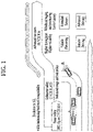
- FIG. 1 is a diagram illustrating V2X communication based on pre-NR RAT and V2X communication based on NR in comparison.
- V2X communication For V2X communication, a technique of providing safety service based on V2X messages such as basic safety message (BSM), cooperative awareness message (CAM), and decentralized environmental notification message (DENM) was mainly discussed in the pre-NR RAT.
- the V2X message may include location information, dynamic information, and attribute information.
- a UE may transmit a CAM of a periodic message type and/or a DENM of an event-triggered type to another UE.
- the CAM may include basic vehicle information including dynamic state information such as a direction and a speed, vehicle static data such as dimensions, an external lighting state, path details, and so on.
- the UE may broadcast the CAM which may have a latency less than 100ms.
- the UE may generate the DENM and transmit the DENM to another UE.
- all vehicles within the transmission range of the UE may receive the CAM and/or the DENM.
- the DENM may have priority over the CAM
- V2X scenarios are presented in NR.
- the V2X scenarios include vehicle platooning, advanced driving, extended sensors, and remote driving.
- vehicles may be dynamically grouped and travel together based on vehicle platooning.
- the vehicles of the group may receive periodic data from a leading vehicle.
- the vehicles of the group may widen or narrow their gaps based on the periodic data.
- a vehicle may be semi-automated or full-automated based on advanced driving.
- each vehicle may adjust a trajectory or maneuvering based on data obtained from a nearby vehicle and/or a nearby logical entity.
- each vehicle may also share a dividing intention with nearby vehicles.
- raw or processed data obtained through local sensor or live video data may be exchanged between vehicles, logical entities, terminals of pedestrians and/or V2X application servers. Accordingly, a vehicle may perceive an advanced environment relative to an environment perceivable by its sensor.
- a remote driver or a V2X application may operate or control a remote vehicle on behalf of a person incapable of driving or in a dangerous environment.
- cloud computing-based driving may be used in operating or controlling the remote vehicle.
- access to a cloud-based back-end service platform may also be used for remote driving.
- a scheme of specifying service requirements for various V2X scenarios including vehicle platooning, advanced driving, extended sensors, and remote driving is under discussion in NR-based V2X communication.
- Various embodiments of the present disclosure may provide a method of transmitting and receiving a signal in a wireless communication system and an apparatus for supporting the method.
- various embodiments of the present disclosure may provide a UE-based TDoA positioning method in a wireless communication system and an apparatus for supporting the method.
- Various embodiments of the present disclosure may provide a method of transmitting and receiving a signal in a wireless communication system and an apparatus for supporting the same.
- a method of a user equipment (UE) in a wireless communication system includes receiving a physical sidelink control channel (PSCCH) from a plurality of anchor nodes (ANs), and receiving a plurality of first positioning reference signals (PRSs) for positioning based on the PSCCH from the plurality of ANs, wherein the PSCCH includes information on a positioning quality indicator (PQI) of each of the plurality of ANs, and the positioning is performed based on a plurality of second PRSs selected based on the information on the PQI among the plurality of first PRSs.
- PQI positioning quality indicator
- the plurality of second PRSs may be received from an AN having a PQI equal to or greater than a preset threshold among the plurality of ANs.
- the plurality of ANs may each be an AN that reserves a PRS pattern for one PRS among the plurality of PRSs by sensing the PSCCH among a plurality of candidate ANs.
- the method may further include transmitting information on a PQI requirement for determining the plurality of candidate ANs.
- the method may further include receiving information related to the positioning and information on a PRS slot in which the PRS is received.
- Information related to the positioning may include at least one of a cyclic-shift value of a sequence of each of the plurality of PRSs or comb type information of each of the plurality of PRSs, and information on the PRS slot may include at least one of a number of the PRS slot, a period of the PRS slot, or offset information of the PRS.
- an apparatus for a user equipment (UE) in a wireless communication system includes at least one processor, and at least one memory operatively connected to the at least one processor and configured to store at least one instruction for allowing the at least one processor to perform operations, wherein the operations includes receiving a physical sidelink control channel (PSCCH) from a plurality of anchor nodes (ANs), and receiving a plurality of first positioning reference signals (PRSs) for positioning based on the PSCCH from the plurality of ANs, and the PSCCH includes information on a positioning quality indicator (PQI) of each of the plurality of ANs, and the positioning is performed based on a plurality of second PRSs selected based on the information on the PQI among the plurality of first PRSs.
- PQI positioning quality indicator
- the plurality of second PRSs may be received from an AN having a PQI equal to or greater than a preset threshold among the plurality of ANs.
- the plurality of ANs may each be an AN that reserves a PRS pattern for one PRS among the plurality of PRSs by sensing the PSCCH among a plurality of candidate ANs.
- the operations may further include transmitting information on a PQI requirement for determining the plurality of candidate ANs.
- the operations may further include receiving information related to the positioning and information on a PRS slot in which the PRS is received.
- Information related to the positioning may include at least one of a cyclic-shift value of a sequence of each of the plurality of PRSs or comb type information of each of the plurality of PRSs, and information on the PRS slot may include at least one of a number of the PRS slot, a period of the PRS slot, or offset information of the PRS.
- the UE may be an autonomous driving vehicle or may be included in the autonomous driving vehicle.
- Another aspect of the present disclosure provides a processor for performing operations for a user equipment (UE) in a wireless communication system, the operations including receiving a physical sidelink control channel (PSCCH) from a plurality of anchor nodes (ANs), and receiving a plurality of first positioning reference signals (PRSs) for positioning based on the PSCCH from the plurality of ANs, wherein the PSCCH includes information on a positioning quality indicator (PQI) of each of the plurality of ANs, and the positioning is performed based on a plurality of second PRSs selected based on the information on the PQI among the plurality of first PRSs.
- PQI positioning quality indicator
- Another aspect of the present disclosure provides a computer-readable recording medium for storing at least one computer program including at least one instruction for allowing at least one processor to perform operations for a user equipment (UE) when being executed by the at least one processor, the operations includingreceiving a physical sidelink control channel (PSCCH) from a plurality of anchor nodes (ANs), and receiving a plurality of first positioning reference signals (PRSs) for positioning based on the PSCCH from the plurality of ANs, wherein the PSCCH includes information on a positioning quality indicator (PQI) of each of the plurality of ANs, and the positioning is performed based on a plurality of second PRSs selected based on the information on the PQI among the plurality of first PRSs.
- PQI positioning quality indicator
- Various embodiments of the present disclosure may provide a UE-based TDoA positioning method in a wireless communication system and an apparatus for supporting the method.
- A/B may mean “A and/or B”.
- A, B may mean “A and/or B”.
- A/B/C may mean “at least one of A, B and/or C”.
- A, B, C may mean “at least one of A, B and/or C”.
- CDMA code division multiple access
- FDMA frequency division multiple access
- TDMA time division multiple access
- OFDMA orthogonal frequency division multiple access
- SC-FDMA single carrier-frequency division multiple access
- CDMA may be implemented as a radio technology such as universal terrestrial radio access (UTRA) or CDMA2000.
- TDMA may be implemented as a radio technology such as global system for mobile communications (GSM)/general packet radio service (GPRS)/Enhanced Data Rates for GSM Evolution (EDGE).
- GSM global system for mobile communications
- GPRS general packet radio service
- EDGE Enhanced Data Rates for GSM Evolution
- OFDMA may be implemented as a radio technology such as IEEE 802.11 (Wi-Fi), IEEE 802.16 (WiMAX), IEEE 802.20, evolved-UTRA (E-UTRA), or the like.
- IEEE 802.16m is an evolution of IEEE 802.16e, offering backward compatibility with an IRRR 802.16e-based system.
- UTRA is a part of universal mobile telecommunications system (UMTS).
- 3rd generation partnership project (3GPP) long term evolution (LTE) is a part of evolved UMTS (E-UMTS) using evolved UTRA (E-UTRA).
- 3GPP LTE employs OFDMA for downlink (DL) and SC-FDMA for uplink (UL).
- LTE-advanced (LTE-A) is an evolution of 3GPP LTE.
- 5G new radio access technology is a new clean-state mobile communication system characterized by high performance, low latency, and high availability.
- 5G NR may use all available spectral resources including a low frequency band below 1GHz, an intermediate frequency band between 1GHz and 10GHz, and a high frequency (millimeter) band of 24GHz or above.
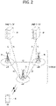
- FIG. 2 illustrates the structure of an LTE system according to an embodiment of the present disclosure. This may also be called an evolved UMTS terrestrial radio access network (E-UTRAN) or LTE/LTE-A system.
- E-UTRAN evolved UMTS terrestrial radio access network
- LTE/LTE-A system LTE/LTE-A system
- the E-UTRAN includes evolved Node Bs (eNBs) 20 which provide a control plane and a user plane to UEs 10.
- a UE 10 may be fixed or mobile, and may also be referred to as a mobile station (MS), user terminal (UT), subscriber station (SS), mobile terminal (MT), or wireless device.
- An eNB 20 is a fixed station communication with the UE 10 and may also be referred to as a base station (BS), a base transceiver system (BTS), or an access point.
- BS base station
- BTS base transceiver system
- eNBs 20 may be connected to each other via an X2 interface.
- An eNB 20 is connected to an evolved packet core (EPC) 39 via an S1 interface. More specifically, the eNB 20 is connected to a mobility management entity (MME) via an S1-MME interface and to a serving gateway (S-GW) via an S1-U interface.
- EPC evolved packet core
- MME mobility management entity
- S-GW serving gateway
- the EPC 30 includes an MME, an S-GW, and a packet data network-gateway (P-GW).
- the MME has access information or capability information about UEs, which are mainly used for mobility management of the UEs.
- the S-GW is a gateway having the E-UTRAN as an end point
- the P-GW is a gateway having a packet data network (PDN) as an end point.
- PDN packet data network
- the radio protocol stack between a UE and a network may be divided into Layer 1 (L1), Layer 2 (L2) and Layer 3 (L3). These layers are defined in pairs between a UE and an Evolved UTRAN (E-UTRAN), for data transmission via the Uu interface.
- L1 Layer 1
- L2 Layer 2
- L3 Layer 3
- PHY physical
- RRC radio resource control
- FIG. 3(a) illustrates a user-plane radio protocol architecture according to an embodiment of the disclosure.
- FIG. 3(b) illustrates a control-plane radio protocol architecture according to an embodiment of the disclosure.
- a user plane is a protocol stack for user data transmission
- a control plane is a protocol stack for control signal transmission.
- the PHY layer provides an information transfer service to its higher layer on physical channels.
- the PHY layer is connected to the medium access control (MAC) layer through transport channels and data is transferred between the MAC layer and the PHY layer on the transport channels.
- the transport channels are divided according to features with which data is transmitted via a radio interface.
- the physical channels may be modulated in orthogonal frequency division multiplexing (OFDM) and use time and frequencies as radio resources.
- OFDM orthogonal frequency division multiplexing
- the MAC layer provides services to a higher layer, radio link control (RLC) on logical channels.
- RLC radio link control
- the MAC layer provides a function of mapping from a plurality of logical channels to a plurality of transport channels. Further, the MAC layer provides a logical channel multiplexing function by mapping a plurality of logical channels to a single transport channel.
- a MAC sublayer provides a data transmission service on the logical channels.
- the RLC layer performs concatenation, segmentation, and reassembly for RLC serving data units (SDUs).
- SDUs RLC serving data units
- the RLC layer provides three operation modes, transparent mode (TM), unacknowledged mode (UM), and acknowledged Mode (AM).
- TM transparent mode
- UM unacknowledged mode
- AM acknowledged Mode
- An AM RLC provides error correction through automatic repeat request (ARQ).
- the RRC layer is defined only in the control plane and controls logical channels, transport channels, and physical channels in relation to configuration, reconfiguration, and release of RBs.
- An RB refers to a logical path provided by L1 (the PHY layer) and L2 (the MAC layer, the RLC layer, and the packet data convergence protocol (PDCP) layer), for data transmission between the UE and the network.
- L1 the PHY layer
- L2 the MAC layer, the RLC layer, and the packet data convergence protocol (PDCP) layer
- the user-plane functions of the PDCP layer include user data transmission, header compression, and ciphering.
- the control-plane functions of the PDCP layer include control-plane data transmission and ciphering/integrity protection.
- RB establishment amounts to a process of defining radio protocol layers and channel features and configuring specific parameters and operation methods in order to provide a specific service.
- RBs may be classified into two types, signaling radio bearer (SRB) and data radio bearer (DRB).
- SRB is used as a path in which an RRC message is transmitted on the control plane
- DRB is used as a path in which user data is transmitted on the user plane.
- RRC_INACTIVE state is additionally defined.
- a UE in the RRC_INACTIVE state may maintain a connection to a core network, while releasing a connection from an eNB.
- DL transport channels carrying data from the network to the UE include a broadcast channel (BCH) on which system information is transmitted and a DL shared channel (DL SCH) on which user traffic or a control message is transmitted. Traffic or a control message of a DL multicast or broadcast service may be transmitted on the DL-SCH or a DL multicast channel (DL MCH).
- UL transport channels carrying data from the UE to the network include a random access channel (RACH) on which an initial control message is transmitted and an UL shared channel (UL SCH) on which user traffic or a control message is transmitted.
- RACH random access channel
- UL SCH UL shared channel
- the logical channels which are above and mapped to the transport channels include a broadcast control channel (BCCH), a paging control channel (PCCH), a common control channel (CCCH), a multicast control channel (MCCH), and a multicast traffic channel (MTCH).
- BCCH broadcast control channel
- PCCH paging control channel
- CCCH common control channel
- MCCH multicast control channel
- MTCH multicast traffic channel
- a physical channel includes a plurality of OFDM symbol in the time domain by a plurality of subcarriers in the frequency domain.
- One subframe includes a plurality of OFDM symbols in the time domain.
- An RB is a resource allocation unit defined by a plurality of OFDM symbols by a plurality of subcarriers.
- each subframe may use specific subcarriers of specific OFDM symbols (e.g., the first OFDM symbol) in a corresponding subframe for a physical DL control channel (PDCCH), that is, an L1/L2 control channel.
- a transmission time interval (TTI) is a unit time for subframe transmission.
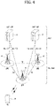
- FIG. 4 illustrates the structure of an NR system according to an embodiment of the present disclosure.
- a next generation radio access network may include a next generation Node B (gNB) and/or an eNB, which provides user-plane and control-plane protocol termination to a UE.
- the NG-RAN is shown as including only gNBs, by way of example.
- a gNB and an eNB are connected to each other via an Xn interface.
- the gNB and the eNB are connected to a 5G core network (5GC) via an NG interface.
- 5GC 5G core network
- the gNB and the eNB are connected to an access and mobility management function (AMF) via an NG-C interface and to a user plane function (UPF) via an NG-U interface.
- AMF access and mobility management function
- UPF user plane function
- FIG. 5 illustrates functional split between the NG-RAN and the 5GC according to an embodiment of the present disclosure.
- a gNB may provide functions including inter-cell radio resource management (RRM), radio admission control, measurement configuration and provision, and dynamic resource allocation.
- the AMF may provide functions such as non-access stratum (NAS) security and idle-state mobility processing.
- the UPF may provide functions including mobility anchoring and protocol data unit (PDU) processing.
- a session management function (SMF) may provide functions including UE Internet protocol (IP) address allocation and PDU session control.
- IP Internet protocol
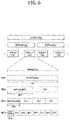
- FIG. 6 illustrates a radio frame structure in NR, to which embodiment(s) of the present disclosure is applicable.
- a radio frame may be used for UL transmission and DL transmission in NR.
- a radio frame is 10ms in length, and may be defined by two 5-ms half-frames.
- An HF may include five 1-ms subframes.
- a subframe may be divided into one or more slots, and the number of slots in an SF may be determined according to a subcarrier spacing (SCS).
- SCS subcarrier spacing
- Each slot may include 12 or 14 OFDM(A) symbols according to a cyclic prefix (CP).
- CP cyclic prefix
- each slot may include 14 symbols, whereas in an extended CP (ECP) case, each slot may include 12 symbols.
- a symbol may be an OFDM symbol (or CP-OFDM symbol) or an SC-FDMA symbol (or DFT-s-OFDM symbol).
- Table 1 lists the number of symbols per slot Nslotsymb, the number of slots per frame Nframe,uslot, and the number of slots per subframe Nsubframe,uslot according to an SCS configuration ⁇ in the NCP case.
- different OFDM(A) numerologies e.g., SCSs, CP lengths, and so on
- SCSs subframe, slot, or TTI
- TU time unit
- various numerologies or SCSs may be supported to support various 5G services. For example, with an SCS of 15kHz, a wide area in traditional cellular bands may be supported, while with an SCS of 30kHz/60kHz, a dense urban area, a lower latency, and a wide carrier bandwidth may be supported. With an SCS of 60kHz or higher, a bandwidth larger than 24.25GHz may be supported to overcome phase noise.
- An NR frequency band may be defined by two types of frequency ranges, FR1 and FR2.
- the numerals in each frequency range may be changed.
- the two types of frequency ranges may be given in [Table 3].
- FR1 may be a "sub 6GHz range”
- FR2 may be an "above 6GHz range” called millimeter wave (mmW).
- mmW millimeter wave
- [Table 3] Frequency Range designation Corresponding frequency range Subcarrier Spacing (SCS) FR1 450MHz - 6000MHz 15, 30, 60kHz FR2 24250MHz - 52600MHz 60, 120, 240kHz
- SCS Corresponding frequency range Subcarrier Spacing
- FR1 may range from 410MHz to 7125MHz as listed in [Table 4]. That is, FR1 may include a frequency band of 6GHz (or 5850, 5900, and 5925MHz) or above.
- the frequency band of 6GHz (or 5850, 5900, and 5925MHz) or above may include an unlicensed band.
- the unlicensed band may be used for various purposes, for example, vehicle communication (e.g., autonomous driving).
- SCS Corresponding frequency range Subcarrier Spacing
- FIG. 7 illustrates a slot structure in an NR frame according to an embodiment of the present disclosure.
- a slot includes a plurality of symbols in the time domain.
- one slot may include 14 symbols in an NCP case and 12 symbols in an ECP case.
- one slot may include 7 symbols in an NCP case and 6 symbols in an ECP case.
- a carrier includes a plurality of subcarriers in the frequency domain.
- An RB may be defined by a plurality of (e.g., 12) consecutive subcarriers in the frequency domain.
- a bandwidth part (BWP) may be defined by a plurality of consecutive (physical) RBs ((P)RBs) in the frequency domain and correspond to one numerology (e.g., SCS, CP length, or the like).
- a carrier may include up to N (e.g., 5) BWPs. Data communication may be conducted in an activated BWP.
- Each element may be referred to as a resource element (RE) in a resource grid, to which one complex symbol may be mapped.
- RE resource element
- a radio interface between UEs or a radio interface between a UE and a network may include L1, L2, and L3.
- L1 may refer to the PHY layer.
- L2 may refer to at least one of the MAC layer, the RLC layer, the PDCH layer, or the SDAP layer.
- L3 may refer to the RRC layer.
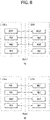
- FIG. 8 illustrates a radio protocol architecture for SL communication according to an embodiment of the present disclosure. Specifically, FIG. 8(a) illustrates a user-plane protocol stack in LTE, and FIG. 8(b) illustrates a control-plane protocol stack in LTE.
- FIG. 9 illustrates a radio protocol architecture for SL communication according to an embodiment of the present disclosure. Specifically, FIG. 9(a) illustrates a user-plane protocol stack in NR, and FIG. 9(b) illustrates a control-plane protocol stack in NR
- SLSSs Sidelink synchronization signals
- synchronization information will be described below.
- the SLSSs which are SL-specific sequences, may include a primary sidelink synchronization signal (PSSS) and a secondary sidelink synchronization signal (SSSS).
- PSSS primary sidelink synchronization signal
- SSSS secondary sidelink synchronization signal
- the PSSS may be referred to as a sidelink primary synchronization signal (S-PSS)
- S-SSS sidelink secondary synchronization signal
- S-SSS sidelink secondary synchronization signal
- length-127 M-sequences may be used for the S-PSS
- length-127 gold-sequences may be used for the S-SSS.
- the UE may detect an initial signal and acquire synchronization by using the S-PSS.
- the UE may acquire fine synchronization and detect a synchronization signal ID, by using the S-PSS and the S-SSS.
- a physical sidelink broadcast channel may be a (broadcast) channel carrying basic (system) information that the UE needs to first know before transmitting and receiving an SL signal.
- the basic information may include information related to the SLSSs, duplex mode (DM) information, time division duplex (TDD) UL/DL (UL/DL) configuration information, resource pool-related information, information about the type of an application related to the SLSSs, subframe offset information, broadcast information, and so on.
- the payload size of the PSBCH may be 56 bits, including a 24-bit cyclic redundancy check (CRC), for evaluation of PSBCH performance in NR V2X.
- CRC cyclic redundancy check
- the S-PSS, S-SSS, and PSBCH may be included in a block format (e.g., SL synchronization signal (SL SS)/PSBCH block, hereinafter, referred to as sidelink-synchronization signal block (S-SSB)) supporting periodic transmission.
- the S-SSB may have the same numerology (i.e., SCS and CP length) as a physical sidelink control channel (PSCCH)/physical sidelink shared channel (PSSCH) in a carrier, and the transmission bandwidth of the S-SSB may be within a (pre)configured SL BWP.
- the bandwidth of the S-SSB may be 11 RBs.
- the PSBCH may span 11 RBs.
- the frequency position of the S-SSB may be (pre)set. Therefore, the UE does not need to perform hypothesis detection in a frequency to discover the S-SSB in the carrier.
- a plurality of numerologies including different SCSs and/or CP lengths may be supported.
- the length of a time resource for S-SSB transmission of a UE may be shortened.
- a transmitting UE may transmit one or more S-SSBs to a receiving terminal within one S-SSB transmission period according to the SCS.
- the number of S-SSBs that the transmitting terminal transmits to the receiving terminal within one S-SSB transmission period may be pre-configured or configured for the transmitting UE.
- the S-SSB transmission period may be 160ms.
- an S-SSB transmission period of 160ms may be supported.
- the transmitting UE may transmit one or two S-SSBs to the receiving UE within one S-SSB transmission period. For example, when the SCS is 30kHz in FR1, the transmitting UE may transmit one or two S-SSBs to the receiving UE within one S-SSB transmission period. For example, when the SCS is 60kHz in FR1, the transmitting UE may transmit one, two or four S-SSBs to the receiving UE within one S-SSB transmission period.
- the transmitting UE may transmit 1, 2, 4, 8, 16, or 32 S-SSBs to the receiving UE within one S-SSB transmission period.
- the transmitting UE may transmit 1, 2, 4, 8, 16, 32, or 64 S-SSBs to the receiving UE within one S-SSB transmission period.
- the structure of an S-SSB transmitted by the transmitting UE to the receiving UE may be different according to a CP type.
- the CP type may be an NCP or an ECP Specifically, for example, when the CP type is NCP, the number of symbols to which the PSBCH is mapped in the S-SSB transmitted by the transmitting UE may be 9 or 8.
- the CP type is ECP
- the number of symbols to which the PSBCH is mapped in the S-SSB transmitted by the transmitting UE may be 7 or 6.
- the PSBCH may be mapped to the first symbol of the S-SSB transmitted by the transmitting UE.
- the receiving UE may perform an automatic gain control (AGC) operation in the first symbol period of the S-SSB.
- AGC automatic gain control
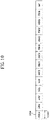
- FIG. 10 illustrates the structure of an S-SSB in an NCP case according to an embodiment of the present disclosure.
- FIG. 10 may be referred to for the structure of the S-SSB, that is, the order of symbols to which the S-PSS, S-SSS and PSBCH are mapped in the S-SSB transmitted by the transmitting UE.
- FIG. 11 illustrates the structure of an S-SSB in an ECP case according to an embodiment of the present disclosure.
- the number of symbols to which the PSBCH is mapped after the S-SSS in the S-SSB may be 6, unlike FIG. 10 . Therefore, the coverage of the S-SSB may be different depending on whether the CP type is NCP or ECP.
- Each SLSS may have a sidelink synchronization identifier (SLSS ID).
- SLSS ID sidelink synchronization identifier
- the values of SLSS IDs may be defined based on combinations of two different S-PSS sequences and 168 different S-SSS sequences.
- the number of SLSS IDs may be 336.
- the value of an SLSS ID may be any one of 0 to 335.
- the values of SLSS IDs may be defined based on combinations of two different S-PSS sequences and 336 different S-SSS sequences.
- the number of SLSS IDs may be 672.
- the value of an SLSS ID may be any one of 0 to 671.
- one of the two different S-PSSs may be associated with in-coverage and the other S-PSS may be associated with out-of-coverage.
- the SLSS ID of 0 to 335 may be used for in-coverage
- the SLSS IDs of 336 to 671 may be used for out-coverage.
- the transmitting UE needs to optimize transmission power according to the characteristics of each signal included in the S-SSB. For example, the transmitting UE may determine a maximum power reduction (MPR) value for each signal included in the S-SSB according to the peak-to-average power ratio (PAPR) of the signal. For example, when the PAPR value is different between the S-PSS and the S-SSS in the S-SSB, the transmitting UE may apply an optimal MPR value to each of the S-PSS and the S-SSS to improve the S-SSB reception performance of the receiving UE. For example, a transition period may further be applied so that the transmitting UE performs an amplification operation for each signal.
- MPR maximum power reduction
- PAPR peak-to-average power ratio
- the transition period may preserve a time required for a transmission-end amplifier of the transmitting UE to perform a normal operation at the boundary at which the transmission power of the transmitting UE is changed.
- the transition period may be 10us in FR1, and 5us in FR2.
- a search window in which the receiving UE detects the S-PSS may be 80ms and/or 160ms.
- FIG. 12 illustrates UEs that conduct V2X or SL communication between them according to an embodiment of the present disclosure.
- the term "UE” in V2X or SL communication may mainly refer to a terminal of a user.
- the BS may also be regarded as a kind of UE.
- a first UE may be a first device 100 and a second UE (UE2) may be a second device 200.
- UE1 may select a resource unit corresponding to specific resources in a resource pool which is a set of resources. UE1 may then transmit an SL signal in the resource unit.
- UE2 which is a receiving UE, may be configured with the resource pool in which UE1 may transmit a signal, and detect the signal from UE1 in the resource pool.
- the BS may indicate the resource pool to UE1.
- another UE may indicate the resource pool to UE1, or UE1 may use a predetermined resource pool.
- a resource pool may include a plurality of resource units, and each UE may select one or more resource units and transmit an SL signal in the selected resource units.
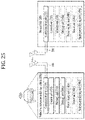
- FIG. 13 illustrates resource units for V2X or SL communication according to an embodiment of the present disclosure.
- the total frequency resources of a resource pool may be divided into NF frequency resources, and the total time resources of the resource pool may be divided into NT time resources.
- a total of NF ⁇ NT resource units may be defined in the resource pool.
- FIG. 13 illustrates an example in which the resource pool is repeated with a periodicity of NT subframes.
- one resource unit (e.g., Unit #0) may appear repeatedly with a periodicity.
- the index of a physical resource unit to which one logical resource unit is mapped may change over time in a predetermined pattern.
- a resource pool may refer to a set of resource units available to a UE for transmission of an SL signal.
- Resource pools may be divided into several types. For example, each resource pool may be classified as follows according to the content of an SL signal transmitted in the resource pool.
- a scheduling assignment may be a signal including information about the position of resources used for a transmitting UE to transmit an SL data channel, a modulation and coding scheme (MCS) or multiple input multiple output (MIMO) transmission scheme required for data channel demodulation, a timing advertisement (TA), and so on.
- MCS modulation and coding scheme
- MIMO multiple input multiple output
- TA timing advertisement
- the SA may be multiplexed with the SL data in the same resource unit, for transmission.
- an SA resource pool may refer to a resource pool in which an SA is multiplexed with SL data, for transmission.
- the SA may be referred to as an SL control channel.
- An SL data channel may be a resource pool used for a transmitting UE to transmit user data.
- PSSCH SL data channel
- an SA is multiplexed with SL data in the same resource unit, for transmission, only the SL data channel except for SA information may be transmitted in a resource pool for the SL data channel.
- REs used to transmit the SA information in an individual resource unit in an SA resource pool may still be used to transmit SL data in the resource pool of the SL data channel.
- the transmitting UE may transmit the PSSCH by mapping the PSSCH to consecutive PRBs.
- a discovery channel may be a resource pool used for a transmitting UE to transmit information such as its ID.
- the transmitting UE may enable a neighboring UE to discover itself on the discovery channel.
- a different resources pool may be used for an SL signal according to a transmission timing determination scheme for the SL signal (e.g., whether the SL signal is transmitted at a reception time of a synchronization reference signal (RS) or at a time resulting from applying a predetermined TA to the reception time), a resource allocation scheme for the SL signal (e.g., whether a BS allocates transmission resources of an individual signal to an individual transmitting UE or whether the individual transmitting UE selects its own individual signal transmission resources in the resource pool), the signal format of the SL signal (e.g., the number of symbols occupied by each SL signal in one subframe, or the number of subframes used for transmission of one SL signal), the strength of a signal from the BS, the transmission power of the SL UE, and so on.
- a transmission timing determination scheme for the SL signal e.g., whether the SL signal is transmitted at a reception time of a synchronization reference signal (RS) or at a time resulting from applying
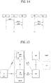
- FIG. 14 illustrates a procedure of performing V2X or SL communication according to a transmission mode in a UE according to an embodiment of the present disclosure.
- a transmission mode may also be referred to as a mode or a resource allocation mode.
- a transmission mode in LTE may be referred to as an LTE transmission mode
- a transmission mode in NR may be referred to as an NR resource allocation mode.
- FIG. 14 (a) illustrates a UE operation related to LTE transmission mode 1 or LTE transmission mode 3.
- FIG. 14 (a) illustrates a UE operation related to NR resource allocation mode 1.
- LTE transmission mode 1 may be applied to general SL communication
- LTE transmission mode 3 may be applied to V2X communication.
- FIG. 14 (b) illustrates a UE operation related to LTE transmission mode 2 or LTE transmission mode 4.
- FIG. 14 (b) illustrates a UE operation related to NR resource allocation mode 2.
- a BS may schedule SL resources to be used for SL transmission of a UE.
- the BS may perform resource scheduling for UE1 through a PDCCH (more specifically, DL control information (DCI)), and UE1 may perform V2X or SL communication with UE2 according to the resource scheduling.
- DCI DL control information
- UE1 may transmit sidelink control information (SCI) to UE2 on a PSCCH, and then transmit data based on the SCI to UE2 on a PSSCH.
- SCI sidelink control information
- a UE may be provided with or allocated resources for one or more SL transmissions of one transport block (TB) by a dynamic grant from the BS.
- the BS may provide the UE with resources for transmission of a PSCCH and/or a PSSCH by the dynamic grant.
- a transmitting UE may report an SL hybrid automatic repeat request (SL HARQ) feedback received from a receiving UE to the BS.
- SL HARQ SL hybrid automatic repeat request
- PUCCH resources and a timing for reporting the SL HARQ feedback to the BS may be determined based on an indication in a PDCCH, by which the BS allocates resources for SL transmission.
- the DCI may indicate a slot offset between the DCI reception and a first SL transmission scheduled by the DCI.
- a minimum gap between the DCI that schedules the SL transmission resources and the resources of the first scheduled SL transmission may not be smaller than a processing time of the UE.
- the UE may be periodically provided with or allocated a resource set for a plurality of SL transmissions through a configured grant from the BS.
- the grant to be configured may include configured grant type 1 or configured grant type 2.
- the UE may determine a TB to be transmitted in each occasion indicated by a given configured grant.
- the BS may allocate SL resources to the UE in the same carrier or different carriers.
- an NR gNB may control LTE-based SL communication.
- the NR gNB may transmit NR DCI to the UE to schedule LTE SL resources.
- a new RNTI may be defined to scramble the NR DCI.
- the UE may include an NR SL module and an LTE SL module.
- the NR SL module may convert the NR SL DCI into LTE DCI type 5A, and transmit LTE DCI type 5A to the LTE SL module every Xms.
- the LTE SL module may activate and/or release a first LTE subframe after Z ms.
- X may be dynamically indicated by a field of the DCI.
- a minimum value of X may be different according to a UE capability.
- the UE may report a single value according to its UE capability.
- X may be positive.
- the UE may determine SL transmission resources from among SL resources preconfigured or configured by the BS/network.
- the preconfigured or configured SL resources may be a resource pool.
- the UE may autonomously select or schedule SL transmission resources.
- the UE may select resources in a configured resource pool on its own and perform SL communication in the selected resources.
- the UE may select resources within a selection window on its own by a sensing and resource (re)selection procedure.
- the sensing may be performed on a subchannel basis.
- UE1 which has autonomously selected resources in a resource pool, may transmit SCI to UE2 on a PSCCH and then transmit data based on the SCI to UE2 on a PSSCH.
- a UE may help another UE with SL resource selection.
- the UE in NR resource allocation mode 2, the UE may be configured with a grant configured for SL transmission.
- the UE may schedule SL transmission for another UE.
- the UE in NR resource allocation mode 2, the UE may reserve SL resources for blind retransmission.
- UE1 may indicate the priority of SL transmission to UE2 by SCI.
- UE2 may decode the SCI and perform sensing and/or resource (re)selection based on the priority.
- the resource (re)selection procedure may include identifying candidate resources in a resource selection window by UE2 and selecting resources for (re)transmission from among the identified candidate resources by UE2.
- the resource selection window may be a time interval during which the UE selects resources for SL transmission.
- the resource selection window may start at T1 ⁇ 0, and may be limited by the remaining packet delay budget of UE2.
- UE2 may not determine the specific resources as candidate resources.
- the SL RSRP threshold may be determined based on the priority of SL transmission indicated by the SCI received from UE1 by UE2 and the priority of SL transmission in the resources selected by UE2.
- the L1 SL RSRP may be measured based on an SL demodulation reference signal (DMRS).
- DMRS SL demodulation reference signal
- one or more PSSCH DMRS patterns may be configured or preconfigured in the time domain for each resource pool.
- PDSCH DMRS configuration type 1 and/or type 2 may be identical or similar to a PSSCH DMRS pattern in the frequency domain.
- an accurate DMRS pattern may be indicated by the SCI.
- the transmitting UE may select a specific DMRS pattern from among DMRS patterns configured or preconfigured for the resource pool.
- the transmitting UE may perform initial transmission of a TB without reservation based on the sensing and resource (re)selection procedure. For example, the transmitting UE may reserve SL resources for initial transmission of a second TB using SCI associated with a first TB based on the sensing and resource (re)selection procedure.
- the UE may reserve resources for feedback-based PSSCH retransmission through signaling related to a previous transmission of the same TB.
- the maximum number of SL resources reserved for one transmission, including a current transmission may be 2, 3 or 4.
- the maximum number of SL resources may be the same regardless of whether HARQ feedback is enabled.
- the maximum number of HARQ (re)transmissions for one TB may be limited by a configuration or preconfiguration.
- the maximum number of HARQ (re)transmissions may be up to 32.
- the configuration or preconfiguration may be for the transmitting UE.
- HARQ feedback for releasing resources which are not used by the UE may be supported.
- the UE may indicate one or more subchannels and/or slots used by the UE to another UE by SCI.
- the UE may indicate one or more subchannels and/or slots reserved for PSSCH (re)transmission by the UE to another UE by SCI.
- a minimum allocation unit of SL resources may be a slot.
- the size of a subchannel may be configured or preconfigured for the UE.
- control information transmitted from a BS to a UE on a PDCCH is referred to as DCI
- control information transmitted from one UE to another UE on a PSCCH may be referred to as SCI.
- the UE may know the starting symbol of the PSCCH and/or the number of symbols in the PSCCH before decoding the PSCCH.
- the SCI may include SL scheduling information.
- the UE may transmit at least one SCI to another UE to schedule the PSSCH.
- one or more SCI formats may be defined.
- the transmitting UE may transmit the SCI to the receiving UE on the PSCCH.
- the receiving UE may decode one SCI to receive the PSSCH from the transmitting UE.
- the transmitting UE may transmit two consecutive SCIs (e.g., 2-stage SCI) on the PSCCH and/or PSSCH to the receiving UE.
- the receiving UE may decode the two consecutive SCIs (e.g., 2-stage SCI) to receive the PSSCH from the transmitting UE.
- SCI configuration fields are divided into two groups in consideration of a (relatively) large SCI payload size
- SCI including a first SCI configuration field group is referred to as first SCI.
- SCI including a second SCI configuration field group may be referred to as second SCI.
- the transmitting UE may transmit the first SCI to the receiving UE on the PSCCH.
- the transmitting UE may transmit the second SCI to the receiving UE on the PSCCH and/or PSSCH.
- the second SCI may be transmitted to the receiving UE on an (independent) PSCCH or on a PSSCH in which the second SCI is piggybacked to data.
- the two consecutive SCIs may be applied to different transmissions (e.g., unicast, broadcast, or groupcast).
- the transmitting UE may transmit all or part of the following information to the receiving UE by SCI.
- the transmitting UE may transmit all or part of the following information to the receiving UE by first SCI and/or second SCI.
- RS e.g., DMRS or the like
- information related to decoding and/or channel estimation of data transmitted on a PSSCH for example, information related to a pattern of (time-frequency) mapping resources of the DMRS, rank information, and antenna port index information.
- the first SCI may include information related to channel sensing.
- the receiving UE may decode the second SCI using the PSSCH DMRS.
- a polar code used for the PDCCH may be applied to the second SCI.
- the payload size of the first SCI may be equal for unicast, groupcast and broadcast in a resource pool.
- the receiving UE does not need to perform blind decoding on the second SCI.
- the first SCI may include scheduling information about the second SCI.
- the PSCCH may be replaced with at least one of the SCI, the first SCI, or the second SC. Additionally or alternatively, for example, the SCI may be replaced with at least one of the PSCCH, the first SCI, or the second SCI. Additionally or alternatively, for example, since the transmitting UE may transmit the second SCI to the receiving UE on the PSSCH, the PSSCH may be replaced with the second SCI.
- a CAM of a periodic message type and a DENM of an event-triggered message type may be transmitted.
- the CAM may include basic vehicle information, such as dynamic state information about a vehicle like a direction and a speed, vehicle static data like dimensions, exterior lighting conditions, route details, and so on.
- the CAM may be 50 to 300 bytes long.
- the CAM is broadcast and has a latency requirement below 100ms.
- the DENM may be a message generated in a sudden situation such as a vehicle breakdown or accident.
- the DENM may be shorter than 3000 bytes, and receivable at any vehicle within a transmission range.
- the DENM may have a higher priority than the CAM
- Carrier reselection will be described below.
- the UE may perform carrier reselection based on the channel busy ratios (CBRs) of configured carriers and/or the PPPP of a V2X message to be transmitted. For example, carrier reselection may be performed in the MAC layer of the UE.
- CBRs channel busy ratios
- PPPP and ProSe per packet reliability may be interchangeably used with each other. For example, as a PPPP value is smaller, this may mean a higher priority, and as the PPPP value is larger, this may mean a lower priority. For example, as a PPPR value is smaller, this may mean higher reliability, and as the PPPR value is larger, this may mean lower reliability.
- a PPPP value related to a service, packet or message with a higher priority may be less than a PPPP value related to a service, packet or message with a lower priority.
- a PPPR value related to a service, packet or message with higher reliability may be less than a PPPR value related to a service, packet or message with lower reliability.
- a CBR may refer to the fraction of sub-channels in a resource pool, of which the sidelink-received signal strength indicator (S-RSSI) measured by the UE is sensed as exceeding a predetermined threshold.
- S-RSSI sidelink-received signal strength indicator
- the UE may select one or more of candidate carriers in an ascending order from the lowest CBR.
- SL measurement and reporting (e.g., measurement and reporting of an RSRP or an RSRQ) between UEs may be considered in SL.
- an RX-UE may receive an RS from a TX-UE and measure the channel state of the TX-UE based on the RS. Further, the RX-UE may report CSI to the TX-UE.
- SL measurement and reporting may include measurement and reporting of a CBR and reporting of location information.
- Examples of CSI for V2X may include a channel quality indicator (CQI), a precoding matrix index (PMI), a rank indicator (RI), an RSRP, an RSRQ, a path gain/pathloss, an SRS resource indicator (SRI), a CSI-RS resource indicator (CRI), an interference condition, a vehicle motion, and so on.
- CQI channel quality indicator
- PMI precoding matrix index
- RI rank indicator
- RSRP RSRQ
- path gain/pathloss an SRS resource indicator
- SRI SRS resource indicator
- CRI CSI-RS resource indicator
- an interference condition a vehicle motion, and so on.
- a CQI, an RI, and a PMI or some of them may be supported in a non-subband-based aperiodic CSI report based on the assumption of four or fewer antenna ports.
- the CSI procedure may not depend on a standalone RS.
- CSI reporting may be activated and deactivated depending on a configuration.
- the TX-UE may transmit a channel state information-reference signal (CSI-RS) to the RX-UE, and the RX-UE may measure a CQI or an RI using the CSI-RS.
- CSI-RS may be referred to as an SL CSI-RS.
- the CSI-RS may be confined to within a PSSCH transmission.
- the TX-UE may transmit the CSI-RS in a PSSCH resource to the RX-UE.
- HARQ Hybrid Automatic Repeat Request
- An error compensation scheme for ensuring communication reliability may include a Forward Error Correction (FEC) scheme and an Automatic Repeat Request (ARQ) scheme.
- FEC Forward Error Correction
- ARQ Automatic Repeat Request
- error at a reception end may be corrected by adding an extra error correction code to information bits.
- the FEC scheme is advantageous in that time delay is low and information that is separately transmitted and received between transmission and reception ends is not required, but is disadvantageous in that system efficiency is degraded in a fine channel environment.
- the ARQ scheme has high transmission reliability, but is disadvantageous in that time delay occurs and system efficiency is degraded in a poor channel environment.
- the Hybrid Automatic Repeat Request (HARQ) scheme is obtained by combining the FEC and the ARQ, and in this case, performance may be improving performance by checking whether data received by a physical layer contains error that is not capable of being decoded and requesting retransmission when error occurs.
- HARQ Hybrid Automatic Repeat Request
- HARQ feedback and HARQ combining at a physical layer may be supported.
- the reception UE may receive a PSSCH from a transmission UE, and the reception UE may transmit HARQ feedback with respect to the PSSCH to the transmission UE using a Sidelink Feedback Control Information (SFCI) format through a physical sidelink feedback channel (PSFCH).
- SFCI Sidelink Feedback Control Information
- the SL HARQ feedback may be enabled for unicast.
- the reception UE may decode the PSCCH with the reception UE as a target, and when the reception UE successfully decodes a transmission block related to the PSCCH, the reception UE may generate an HARQ-ACK.
- the reception UE may transmit the HARQ-ACK to the transmission UE.
- the reception UE may generate the HARQ-NACK.
- the reception UE may transmit the HARQ-NACK to the transmission UE.
- the SL HARQ feedback may be enabled for groupcast.
- two HARQ feedback options may be supported for the groupcast.
- all UEs that perform groupcast communication may share a PSFCH resource.
- UEs belonging to the same group may transmit the HARQ feedback using the same PSFCH resource.
- each UE that performs groupcast communication may use different PSFCH resources in order to transmit the HARQ feedback.
- UEs belonging to the same group may transmit the HARQ feedback using different PSFCH resources.
- the reception UE may determine whether to transmit the HARQ feedback to the transmission UE based on a Transmission-Reception (TX-RX) distance and/or RSRP.
- TX-RX Transmission-Reception
- the reception UE may transmit the HARQ feedback with respect to the PSSCH to the transmission UE.
- the reception UE may not transmit the HARQ feedback with respect to the PSSCH to the transmission UE.
- the transmission UE may notify the reception UE about the position of the transmission UE through SCI related to the PSSCH.
- the SCI related to the PSSCH may be second SCI.
- the reception UE may estimate or acquire the TX-RX distance based on the position of the reception UE and the position of the transmission UE. For example, the reception UE may decode the SCI related to the PSSCH to know the communication range requirement used in the PSSCH.
- a time between the PSFCH and the PSSCH may be configured or preconfigured.
- this may be indicated to an eNB by the UE within coverage using the PUCCH.
- the transmission UE may also transmit indication to a serving eNB of the transmission UE in the form of Scheduling Request (SR)/Buffer Status Report (BSR) that is not the form of HARQ ACK/NACK. Even if the eNB does not receive the indication, the eNB may schedule an SL retransmission resource to the UE.
- SR Scheduling Request
- BSR Buffer Status Report
- a time between the PSFCH and the PSSCH may be configured or preconfigured.
- TDM between the PSCCH/PSSCH and the PSFCH may be allowed for a PSFCH format for SL in a slot.
- a sequence-based PSFCH format having one symbol may be supported.
- the one symbol may not be an AGC period.
- the sequence-based PSFCH format may be applied to unicast and groupcast.
- a PSFCH resource may be periodically configured in N slot periods or preset.
- N may be configured to one or more values equal to or greater than 1.
- N may be 1, 2, or 4.
- the HARQ feedback with respect to transmission in a specific resource pool may be transmitted on only a PSFCH on the specific resource pool.
- slot #(N + A) may include a PSFCH resource.
- A may be the smallest integer equal to or greater than K.
- K may be the number of logical slots.
- K may be the number of slots in a resource pool.
- K may be the number of physical slots.
- K may be number inside and outside the resource pool
- the reception UE may determine a frequency domain and/or a code domain of the PSFCH resource based on an implicit mechanism within an established resource pool. For example, the reception UE may determine the frequency domain and/or the code domain of the PSFCH resource based on at least one of a slot index related to PSCCH/PSSCH/PSFCH, a subchannel related to PSCCH/PSSCH, and/or an identifier for identifying each reception UE from a group for the HARQ feedback based on the groupcast option 2. In addition/alternatively, for example, the reception UE may determine the frequency domain and/or the code domain of the PSFCH resource based on at least one of SL RSRP, SINR, L1 source ID, and/or position information.
- the UE may select any one of HARQ feedback transmission on the PSFCH or HARQ feedback reception on the PSFCH based on a priority rule.
- the priority rule may be based on the minimum priority indication of related PSCCH/PSSCH.
- the UE may select specific HARQ feedback transmission based on the priority rule.
- the priority rule may be based on the minimum priority indication of the related PSCCH/PSSCH.
- FIG. 15 illustrates an exemplary architecture of a 5G system capable of positioning a UE connected to an NG-RAN or an E-UTRAN according to an embodiment of the present disclosure.
- an AMF may receive a request for a location service related to a specific target UE from another entity such as a gateway mobile location center (GMLC) or may autonomously determine to initiate the location service on behalf of the specific target UE.
- the AMF may then transmit a location service request to a location management function (LMF).
- LMF location management function
- the LMF may process the location service request and return a processing result including information about an estimated location of the UE to the AMF.
- the AMF may deliver the processing result received from the LMF to the other entity.
- a new generation evolved-NB (ng-eNB) and a gNB which are network elements of an NG-RAN capable of providing measurement results for positioning, may measure radio signals for the target UE and transmit result values to the LMF.
- the ng-eNB may also control some transmission points (TPs) such as remote radio heads or positioning reference signal (PRS)-dedicated TPs supporting a PRS-based beacon system for an E-UTRA.
- TPs transmission points
- PRS positioning reference signal
- the LMF is connected to an enhanced serving mobile location center (E-SMLC), and the E-SMLC may enable the LMF to access an E-UTRAN.
- E-SMLC may enable the LMF to support observed time difference of arrival (OTDOA), which is one of positioning methods in the E-UTRAN, by using DL measurements obtained by the target UE through signals transmitted by the eNB and/or the PRS-dedicated TPs in the E-UTRAN.
- OTDOA observed time difference of arrival
- the LMF may be connected to an SUPL location platform (SLP).
- the LMF may support and manage different location determination services for target UEs.
- the LMF may interact with the serving ng-eNB or serving gNB of a target UE to obtain a location measurement of the UE.
- the LMF may determine a positioning method based on a location service (LCS) client type, a QoS requirement, UE positioning capabilities, gNB positioning capabilities, and ng-eNB positioning capabilities, and apply the positioning method to the serving gNB and/or the serving ng-eNB.
- the LMF may determine additional information such as a location estimate for the target UE and the accuracy of the position estimation and a speed.
- the SLP is a secure user plane location (SUPL) entity responsible for positioning through the user plane.
- SUPL secure user plane location
- the UE may measure a DL signal through sources such as the NG-RAN and E-UTRAN, different global navigation satellite systems (GNSSes), a terrestrial beacon system (TBS), a wireless local area network (WLAN) access point, a Bluetooth beacon, and a UE barometric pressure sensor.
- GNSSes global navigation satellite systems
- TBS terrestrial beacon system
- WLAN wireless local area network
- the UE may include an LCS application and access the LCS application through communication with a network to which the UE is connected or through another application included in the UE.
- the LCS application may include a measurement and calculation function required to determine the location of the UE.
- the UE may include an independent positioning function such as a global positioning system (GPS) and report the location of the UE independently of an NG-RAN transmission.
- GPS global positioning system
- the independently obtained positioning information may be utilized as auxiliary information of positioning information obtained from the network.
- FIG. 16 illustrates exemplary implementation of a network for positioning a UE according to an embodiment of the present disclosure.
- the AMF may establish a signaling connection with the UE and request a network trigger service to assign a specific serving gNB or ng-eNB This operation is not shown in FIG. 16 . That is, FIG. 16 may be based on the assumption that the UE is in connected mode. However, the signaling connection may be released by the NG-RAN due to signaling and data deactivation during positioning.
- CM-IDLE connection management-IDLE
- a 5GC entity such as a GMLC may request a location service for positioning a target UE to a serving AMF.
- the serving AMF may determine that the location service for positioning the target UE is required in step 1b. For example, for positioning the UE for an emergency call, the serving AMF may determine to perform the location service directly.
- the AMF may then transmit a location service request to an LMF in step 2, and the LMF may start location procedures with the serving-eNB and the serving gNB to obtain positioning data or positioning assistance data in step 3a. Additionally, the LMF may initiate a location procedure for DL positioning with the UE in step 3b. For example, the LMF may transmit positioning assistance data (assistance data defined in 3GPP TS 36.355) to the UE, or obtain a location estimate or location measurement.
- step 3b may be additionally performed after step 3a, step 3b may be performed instead of step 3a.
- the LMF may provide a location service response to the AMF.
- the location service response may include information indicating whether location estimation of the UE was successful and the location estimate of the UE.
- the AMF may deliver the location service response to the 5GC entity such as the GMLC.
- the AMF may use the location service response to provide the location service related to an emergency call or the like.
- FIG. 17 illustrates exemplary protocol layers used to support LTE positioning protocol (LPP) message transmission between an LMF and a UE according to an embodiment of the present disclosure.
- LTP LTE positioning protocol
- An LPP PDU may be transmitted in a NAS PDU between the AMF and the UE.
- the LPP may be terminated between a target device (e.g., a UE in the control plane or a SUPL enabled terminal (SET) in the user plane) and a location server (e.g., an LMF in the control plane or an SLP in the user plane).
- a target device e.g., a UE in the control plane or a SUPL enabled terminal (SET) in the user plane
- a location server e.g., an LMF in the control plane or an SLP in the user plane.
- An LPP message may be transmitted in a transparent PDU over an intermediate network interface by using an appropriate protocol such as the NG application protocol (NGAP) via an NG-control plane (NG-C) interface or a NAS/RRC via LTE-Uu and NR-Uu interfaces.
- NGAP NG application protocol
- N-C NG-control plane
- NAS/RRC
- the target device and the location server may exchange capability information with each other, positioning assistance data and/or location information over the LPP. Further, error information may be exchanged and/or discontinuation of an LPP procedure may be indicated, by an LPP message.
- FIG. 18 illustrates exemplary protocol layers used to support NR positioning protocol A (NRPPa) PDU transmission between an LMF and an NG-RAN node according to an embodiment of the present disclosure.
- NRPPa NR positioning protocol A
- NRPPa may be used for information exchange between the NG-RAN node and the LMF. Specifically, NRPPa enables exchange of an enhanced-cell ID (E-CID) for a measurement transmitted from the ng-eNB to the LMF, data to support OTDOA positioning, and a Cell-ID and Cell location ID for NR Cell ID positioning. Even without information about a related NRPPa transaction, the AMF may route NRPPa PDUs based on the routing ID of the related LMF via an NG-C interface.
- E-CID enhanced-cell ID
- the AMF may route NRPPa PDUs based on the routing ID of the related LMF via an NG-C interface.
- Procedures of the NRPPa protocol for positioning and data collection may be divided into two types.
- One of the two types is a UE-associated procedure for delivering information (e.g., positioning information) about a specific UE, and the other type is a non-UE-associated procedure for delivering information (e.g., gNB/ng-eNB/TP timing information) applicable to an NG-RAN node and related TPs.
- the two types of procedures may be supported independently or simultaneously.
- Positioning methods supported by the NG-RAN include GNSS, OTDOA, E-CID, barometric pressure sensor positioning, WLAN positioning, Bluetooth positioning, terrestrial beacon system (TBS), and UL time difference of arrival (UTDOA).
- GNSS Global System for Mobile Communications
- OTDOA OTDOA
- E-CID E-CID
- barometric pressure sensor positioning WLAN positioning
- Bluetooth positioning Bluetooth positioning
- TBS terrestrial beacon system
- UTDA UL time difference of arrival
- a UE may be positioned in any of the above positioning methods, two or more positioning methods may be used to position the UE.
- OTDOA Observed Time Difference Of Arrival
- FIG. 19 is a diagram illustrating an OTDOA positioning method according to an embodiment of the present disclosure.
- a UE utilizes measurement timings of DL signals received from multiple TPs including an eNB, ng-eNB, and a PRS-dedicated TP.
- the UE measures the timings of the received DL signals using positioning assistance data received from a location server.
- the location of the UE may be determined based on the measurement results and the geographical coordinates of neighboring TPs.
- a UE connected to a gNB may request a measurement gap for OTDOA measurement from a TP.
- the UE fails to identify a single frequency network (SFN) for at least one TP in OTDOA assistance data
- the UE may use an autonomous gap to acquire the SFN of an OTDOA reference cell before requesting a measurement gap in which a reference signal time difference (RSTD) is measured.
- SFN single frequency network
- RSTD reference signal time difference
- An RSTD may be defined based on a smallest relative time difference between the boundaries of two subframes received from a reference cell and a measurement cell, respectively. That is, the RSTD may be calculated based on a relative timing difference between a time when the UE receives the start of a subframe from the reference cell and a time when the UE receives the start of a subframe from the measurement cell which is closest to the subframe received from the reference cell.
- the reference cell may be selected by the UE.
- TOAs time of arrivals
- TP 1, TP 2, and TP 3 may be measured
- RSTD for TP 2-TP 3 may be calculated based on the three TOAs
- geometric hyperbolas may be determined based on the calculated RSTDs
- a point where these hyperbolas intersect may be estimated as the location of the UE.
- Accuracy and/or uncertainty may be involved in each TOA measurement, and thus the estimated UE location may be known as a specific range according to the measurement uncertainty.
- an RSTD for two TPs may be calculated by Equation 1.
- RSTDi , 1 x t ⁇ x i 2 + y t ⁇ y i 2 c ⁇ x t ⁇ x i 2 + y t ⁇ y i 2 c + T i ⁇ T 1 + n i ⁇ n 1
- c is the speed of light
- ⁇ xt, yt ⁇ is the (unknown) coordinates of the target UE
- ⁇ xi, yi ⁇ is the coordinates of a (known) TP
- ⁇ x1, y1 ⁇ is the coordinates of a reference TP (or another TP).
- (Ti-T1) is a transmission time offset between the two TPs, which may be referred to as "real time difference" (RTD)
- ni and n1 may represent values related to UE TOA measurement errors.
- the location of a UE may be measured based on geographic information about the serving ng-eNB, serving gNB and/or serving cell of the UE.
- the geographic information about the serving ng-eNB, the serving gNB, and/or the serving cell may be obtained by paging, registration, or the like.
- an additional UE measurement and/or NG-RAN radio resources may be used to improve a UE location estimate in addition to the CID positioning method.
- E-CID positioning method although some of the same measurement methods as in the measurement control system of the RRC protocol may be used, an additional measurement is generally not performed only for positioning the UE. In other words, a separate measurement configuration or measurement control message may not be provided to position the UE, and the UE may also report a measured value obtained by generally available measurement methods, without expecting that an additional measurement operation only for positioning will be requested.
- the serving gNB may implement the E-CID positioning method using an E-UTRA measurement received from the UE.
- UE measurements E-UTRA RSRP, E-UTRA RSRQ, UE E-UTRA Rx-Tx time difference, GSM EDGE random access network (GERAN)/WLAN RSSI, UTRAN common pilot channel (CPICH) received signal code power (RSCP), and UTRAN CPICH Ec/Io
- GSM EDGE random access network GERAN
- WLAN RSSI GSM EDGE random access network
- CPICH UTRAN common pilot channel
- RSCP received signal code power
- E-UTRAN measurements ng-eNB Rx-Tx time difference, timing advance (TADV), and angle of arrival (AoA)
- TADVs may be classified into Type 1 and Type 2 as follows.
- TADV Type 1 ng ⁇ eNB Rx ⁇ Tx time difference + UE E ⁇ UTRA Rx ⁇ Tx time difference
- TADV Type 2 ng ⁇ eNB Rx ⁇ Tx time difference
- an AoA may be used to measure the direction of the UE.
- the AoA may be defined as an estimated angle of the UE with respect to the location of the UE counterclockwise from a BS/TP.
- a geographical reference direction may be North.
- the BS/TP may use a UL signal such as a sounding reference signal (SRS) and/or a DMRS for AoA measurement.
- SRS sounding reference signal
- DMRS DMRS
- a UTDOA is a method of determining the location of a UE by estimating the arrival time of an SRS.
- a serving cell may be used as a reference cell to estimate the location of the UE based on the difference in arrival time from another cell (or BS/TP).
- an E-SMLC may indicate the serving cell of a target UE to indicate SRS transmission to the target UE. Further, the E-SMLC may provide a configuration such as whether an SRS is periodic/aperiodic, a bandwidth, and frequency/group/ sequence hopping.
- Each symbol of an SRS resource for positioning the UE may be configured in a frequency RE pattern having the Comb-N form.
- Comb-N or N-comb may be a comb-shaped frequency RE pattern or form
- N of Comb-N may refer to a comb-size and may be a value configured via RRC signaling.
- the Comb-N form having a size of N may be achieved by configuring/indicating or allocating an RE of an SRS resource to one RE for every N frequency REs in one symbol.
- comb-offset may refer to a frequency RE offset value in a specific SRS symbol and may have a value of 0 to N - 1.
- the comb-offset may be an offset value used to determine a starting position in the frequency domain of at least one RE (e.g., a SRS RE) configured in the Comb-N form.
- the Comb-N form may be achieved by allocating REs having the lowest frequency index based on one symbol, that is, REs at every N interval in ascending order from the starting position of the RE in the frequency domain.
- a comb type may be a resource mapping type of an RE unit for each of the SRSs and may mean various types of a set of SRS symbols having different comb-offsets.
- Positioning of a UE based on OTDOA of an NR system relates to a method in which a location server/LMF and/or an anchor node (AN) requests the UE to measure and then report RSTD information required for OTDOA positioning through a Uu interface, measures the location of the UE based on the received RSTD information, and then transfers location information to the UE again.
- the positioning method based on the location server/LMF and/or the AN may cause a large delay until the UE finally receives the location information to degrade the reliability of information, and particularly, the physical delay generated in such a positioning operation may greatly degrade the reliability of information as the speed of the UE increases in the NR-V2X system.
- TDoA positioning performed by the UE based on sidelink may be referred to as UE-based Sidelink TDoA Positioning.
- the UE-based sidelink TDoA positioning may be measurement of the location of the UE through sidelink by the UE and the AN in the NR-V2X system, and here, the UE may receive information required for positioning from the AN and may perform positioning.
- a Positioning Reference Signal (PRS) slot for a PRS may be inserted into a sidelink NR-V2X system
- SCI related to an AN may be transmitted through a PSCCH of an NR-V2X slot
- 3) TDoA positioning in the UE and the AN may be performed based on 1) and 2) above.
- PRS Positioning Reference Signal
- the PRS slot may be inserted into the NR-V2X system, and the sidelink TDoA positioning may be performed based on the PRS slot.
- the sidelink TDoA positioning may be performed based on the PRS slot.
- transmission of the NR-V2X service may not be allowed.
- PRS scheduling for TDoA positioning in the PRS slot may be performed through a PSCCH of the NR-V2X slot, and SCI of the AN required to perform TDoA positioning by the UE may be transmitted through the PSCCH of the NR-V2X slot.
- the PSCCH of the NR-V2X slot may mainly include location information of the AN, a Positioning Quality Indicator (PQI) related to the location information of the AN, PRS pattern (or PRS ID) information used in the AN, and location information of the PRS slot used by the AN.
- PQI Positioning Quality Indicator
- PRS pattern or PRS ID
- transmission of the PRS may not be allowed.
- the AN may provide SCI of the AN required to perform TDoA positioning by the UE and the PRS scheduling information through the PSCCH of the NR-V2X slot and may transmit the PRS through the PRS slot.
- the UE may receive the SCI of the AN and the PRS scheduling information by receiving the PSCCH of the NR-V2X slot and may receive the PRS transmitted in the PRS slot to measure ToA.
- Method 1 may propose a structure of a PRS slot inserted to perform sidelink TDoA positioning in an NR-V2X system.
- FIG. 20 is a diagram showing a structure of a PRS slot according to an embodiment of the present disclosure.
- a PRS slot may be additionally inserted into an NR-V2X slot using TDMA in the sidelink NR-V2X system.
- transmission of the NR-V2X service may not be allowed.
- the PRS slot may be arranged and used in various ways according to a TDoA operation and an NR-V2X system operating method. For example, as shown in FIG. 20 , a plurality of PRS slots may be consecutively arranged and used from PRS slot-0 to PRS slot-(T-1). Here, T is the number of consecutive PRS slots.
- the PRS slots may have the same PRS information repeatedly.
- the PRS slots may have different PRS information.
- the PRS slots may be periodically or aperiodically arranged and used. A TDoA operation mode and a related operation in consideration of the aforementioned PRS slot structure will be described below.
- the PRS may be operated in the PRS slot, and in contrast, a PSCCH related to positioning may be operated in the NR-V2X slot. That is, the PSCCH may be transmitted in the NR-V2X slot and the PRS may be transmitted in the PRS slot.
- the PSCCH related to positioning may transmit SCI including the location information of the AN required for TDoA positioning in a UE, Positioning Quality Indicator (PQI) information determining the accuracy of the location information of the AN or a level of a quality of service (QoS), PRS pattern information used in the AN, and information on a period of a PRS slot used in the AN.
- PQI Positioning Quality Indicator
- QoS Quality of service
- FIG. 21 is a diagram showing the structure of a PRS slot.
- the PRS slot may basically include an auto-gain control (AGC) symbol, a PRS, and a guard symbol.
- AGC auto-gain control
- Method 2 discloses various examples of a TDoA positioning operation using a structure of a PRS slot and a method for performing the same.
- the PRS slot may have the structure of the PRS slot disclosed in Method 1, but is not limited thereto.
- TDoA positioning may be performed through 1) a procedure of determining whether an AN participates in a positioning procedure, 2) a procedure of transmitting a PSCCH through an NR-V2X slot positioned before a PRS slot by the AN that participates the positioning procedure and transmitting each PRS through a PRS slot positioned after an NR-V2X slot, and 3) a procedure of receiving each of a PSCCH and a PRS through an NR-V2X slot and a PRS slot and performing TDoA positioning by the UE.
- the PSCCH of the AN transmitted through the NR-V2X slot, may refer to SCI of the AN, required to perform TDoA positioning by the UE, and may have the same meaning unless otherwise stated in the following description.
- TDoA positioning of Method 2 will be described in more detail.
- Step-0 is a step in which an eNB and/or a UE that function as a UE and an AN to perform sidelink TDoA positioning acquires and collects information on a TDoA positioning operation and a structure of a PRS slot. Information related to the TDoA positioning operation and information related to the structure of the PRS slot will be described below.
- information related to the aforementioned structure of the PRS slot and the TDoA positioning operation may be provided through MIB/SIB of a PSBCH and SCI of a PSCCH, transmitted through the NR-V2X slot of FIG. 20 , as configuration information on an NR-V2X system.
- the related information that is, information related to the structure of the PRS slot and the TDoA positioning operation may be changed periodically or aperiodically by the location server/LMF and/or the eNB.
- an eNB and/or a UE that function as a UE and an AN to perform sidelink TDoA positioning may acquire configuration information required for sidelink TDoA positioning by receiving the PSBCH and the PSCCH transmitted through the NR-V2X slot.
- the information related to the aforementioned structure of the PRS slot and the TDoA positioning operation may be provided by predefining default TDoA positioning operation. Accordingly, the eNB and/or the UE that function as the UE and the AN to perform sidelink TDoA positioning may acquire configuration information required for sidelink TDoA positioning using a predefined or stored parameter related to a default PRS slot structure and TDoA positioning operation.
- Step-1 is a first step of sidelink TDoA positioning and is a procedure of determining an eNB and/or a UE to participate in positioning as a candidate AN.
- the candidate AN may refer to a candidate eNB and/or UE to transmit a PRS in a PRS slot.
- a final AN may transmit a PRS in a PRS slot as an eNB and/or a UE that is finally selected among candidate ANs.
- a method of selecting the final AN will be described in [Step-2] below.
- a method of determining a candidate AN to participate in TDoA positioning with respect to an eNB and/or a UE will be described.
- whether to participate in TDoA positioning as the candidate AN may be determined by each eNB and/or each UE based on PQI information of location information.
- each AN may autonomously determine whether a corresponding AN is the candidate AN based on the PQI information of the location information.
- each eNB and/or a UE may perform [Step-2] as the candidate AN, and when the measured PQI is smaller than the specific threshold, each eNB and/or a UE may determine that the corresponding AN is not the candidate AN.
- the specific threshold may be predefined or may be determined by a location server/LMF and/or an eNB or may be transferred to the eNB and the UE.
- whether to participate in TDoA positioning as a candidate AN may be determined by the location server/LMF and/or the eNB.
- the location server/LMF and/or the eNB may notify the UE of whether the corresponding AN is the candidate AN using location information or PQI information reported from the UE. That is, when the candidate AN is a UE, the location server/LMF and/or the eNB may determine whether the corresponding UE is the candidate AN based on the location information or the PQI information and may notify the UE of this.
- the UE may periodically report the location information or the PQI information to the location server/LMF and/or the eNB or may also aperiodically report only upon request from the location server/LMF and/or the eNB.
- separate location information or PQI reporting process may not be required for an eNB and/or a UE having fixed location information.
- whether to participate in TDoA positioning as a candidate AN may be predetermined in advance without the aforementioned determination procedure using location information or PQI or the determination procedure by the location server/LMF and/or the eNB.
- an eNB and/or a UE having fixed location information may always participate in TDoA positioning of a UE as the candidate AN.
- whether to participate in TDoA positioning as a candidate AN may be predetermined based on a PQI requested from the UE to perform TDoA positioning.
- the UE may transmit a minimum PQI requirement that satisfies a local based service (LBS) under consideration through a PSCCH to each eNB and/or each UE, and an eNB and/or a UE that satisfy the corresponding PQI requirement may be a candidate AN or a final AN.
- LBS local based service
- Step-2 is a second step of sidelink TDoA positioning and is a procedure of determining an eNB and/or a UE to participate in positioning as a final AN from candidate ANs.
- the final AN may be selected from the candidate ANs based on sensing between the candidate ANs.
- the candidate AN may sense a PSCCH of an NR-V2X slot that is periodically or aperiodically transmitted to reserve the location of an OFDM symbol for transmitting a PRS pattern and a PRS that are not used or are not supposed to be used by another AN and may not select and reserve a PRS pattern that is used or is supposed to be used by another AN.
- final ANs may each be an AN that reserves a PRS pattern of one PRS among a plurality of PRSs by sensing the PSCCH among a plurality of candidate ANs.
- a PRS pattern reservation process through the aforementioned sensing process may be performed as PRS scheduling in a PRS slot.
- a PRS pattern included in a PRS slot and the number of PRSs may be differently predefined or may be determined by a location server/LMF and/or an eNB and may be transferred to an eNB and a UE.
- the final AN refers to a candidate AN that succeeds in reserving use of a PRS slot among the candidate ANs.
- the final AN may be selected by a location server/LMF and/or an eNB.
- the location server/LMF and/or the eNB may provide information on whether to determine the final AN and information on a PRS pattern to be used in a PRS slot to a UE using location information or PQI information reported from the UE. That is, when the final AN is the UE, the location server/LMF and/or the eNB may transmit information on whether the UE is the final AN and information on the PRS pattern to be used in the PRS slot to the UE using the location information or the PQI information reported from the UE.
- Step-3 is a third step of TDoA positioning and is a procedure of respectively transmitting a PSCCH and a PRS through an NR-V2X slot and a PRS slot by a final AN that is finally selected among candidate ANs in Step-2.
- An AN that is, a final AN may transmit an SCI of location information of each of a plurality of ANs, a PQI of location information of each of the plurality of ANs, and information related to a period of PRS slots through a PSCCH.
- the PQI of the location information may be used to allow the UE to determine whether to consider a corresponding AN in positioning.
- whether to consider the corresponding AN in positioning may mean that the UE selects an AN to be used in TDoA positioning based on Formula 1 among final ANs.
- the threshold may be differently defined depending on the LBS and may be determined by a location server/LMF and an eNB and may be transferred to an eNB and a UE.
- Information on the period of PRS slots of an AN may indicate a time of a subsequent PRS slot and whether the subsequent PRS slot is used and may be information used in a final AN determination procedure through a sensing operation of Step-2.
- an AN may transmit a PRS using a predefined or configured PRS pattern.
- the number of OFDM symbols for a PRS and the location of the OFDM symbol for transmitting the PRS may be predefined or may be determined by a location server/LMF and/or an eNB and may be transferred to an eNB and a UE.
- Step-4 is the last step of sidelink TDoA positioning and a procedure in which a UE receives an NR-V2X slot and a PRS slot and then performs positioning.
- the UE may acquire SCI information related to each AN by decoding a PSCCH of the received TDoA slot and may measure ToA for a PRS transmitted from each AN.
- ToA ToA
- location information of each AN location information of each AN
- PQI information and so on will be described in detail.
- the UE may select a positioning AN using location information of each AN.
- the UE may select a positioning AN for improving positioning performance of the UE in terms of topology.
- the UE may select three ANs that configure a shape closest to an equilateral triangle based on the UE in terms of topology.
- an AN may not be selected when the location of the AN does not help positioning of the UE in terms of topology.
- the UE may select a positioning AN using PQI information provided by each AN. For example, when an LBS service to be performed by the UE requires a PQI equal to or greater than a specific threshold, an AN that provides a PQI less than the threshold may be excluded from a positioning procedure.
- the UE may determine a weight for the positioning AN using location information of each positioning AN. That is, a high weight may be configured for a positioning AN determined to largely affect improvement in positioning performance in terms of topology, and a low weight may be configured for a positioning AN determined to less affect improvement in positioning performance.
- the UE may determine a weight for a positioning AN using PQI information provided by each positioning AN. That is, when a PQI is high, a high weight may be configured for a positioning AN, and a low weight may be configured for a positioning AN that provides a relatively low PQI.
- whether a PQI is high or low may be determined based on an absolute value or may be relatively determined.
- a weight for a positioning AN may be configured based on a threshold of a PQI related to determination of a weight for an AN.
- PQIs for positioning ANs may be compared to configure a weight for a positioning AN.
- a PRS received from the positioning AN may be selected based on at least one of location information or PQI information.
- a PRS received from an AN having a PQI equal to or greater than a preset threshold among the final ANs may be selected as a positioning PRS.
- the UE may measure the location thereof by drawing a hyperbola using the locations of two positioning ANs as focuses using location information and a difference between the two ToA values measured from a pair of positioning ANs, drawing another hyperbola from another pair of TOA values, and then calculating coordinates of an intersection of the two hyperbolas.
- the location of the UE may be corrected or improved by applying a weight for each positioning AN.
- the UE may measure the location thereof by drawing a circle using the location of a positioning AN as a central point using location information and a ToA value measured from each positioning AN and then calculating coordinates of an intersection of a plurality of circles.
- the location of the UE may be corrected or improved by applying a weight for each positioning AN.
- FIG. 22 is a flowchart of a method of receiving a PRS of a UE according to an embodiment of the present disclosure.
- the UE may receive a physical sidelink control channel (PSCCH) from a plurality of anchor nodes (ANs).
- PSCCH may include information on a positioning quality indicator (PQI) of each of the plurality of ANs.
- PQI positioning quality indicator
- the plurality of ANs may each be an AN that reserves a PRS pattern of one PRS among the plurality of PRSs by sensing the PSCCH among a plurality of candidate ANs.
- the UE may receive a plurality of first positioning reference signals (PRSs) for positioning from the plurality of ANs based on the PSCCH.
- PRSs first positioning reference signals
- the positioning may be performed based on a plurality of second PRSs selected based on information on the PQI among the plurality of first PRSs.
- the plurality of second PRSs may each be a PRS received from the AN having a PQI equal to or greater than a preset threshold.
- the method of receiving a PRS may further include transmitting information on a PQI requirement for determining the plurality of candidate ANs.
- the method of receiving a PRS may further include receiving the information related to positioning and the information on the PRS slot in which the PRS is received.
- the information related to positioning may include at least one of a cyclic-shift value of a sequence of each of the plurality of PRSs or comb type information of each of the plurality of PRSs, and
- the information on the PRS slot may include at least one of the number of PRS slots, the period of PRS slots, or offset information of the PRS.
- the UE may directly perform TDoA positioning using sidelink without assistance of a location server/LMF and/or an eNB.
- a UE-based TDoA positioning method may have a very high positioning process speed compared with the position measuring method of the UE through a location server/LMF and/or an eNB.
- interference in a NR-V2X slot and a service operation may not be caused and a sidelink TDoA positioning operation may be performed.
- PRS scheduling may be performed during a procedure of reserving an NR-V2X resource without implementation of a PRS scheduling function for separate TDoA positioning.
- a plurality of UEs may simultaneously perform a positioning operation, and the operation may improve frequency usage efficiency.
- each of the examples of the proposed methods may also be included as one of various embodiments of the present disclosure, and thus each example may be regarded as a kind of proposed method.
- the proposed methods may be implemented independently, some of the proposed methods may be combined (or merged) and implemented.
- the methods proposed in the present disclosure have been described in the context of the 3GPP NR system for convenience of description, the scope of systems to which the proposed methods are applied may be extended to other systems in addition to the 3GPP NR system.
- the proposed methods of the present disclosure may be extended and applied to D2D communication.
- D2D communication refers to direct communication between UEs over a radio channel.
- a network equipment such as a BS may also be regarded as a kind of UE if the network equipment transmits and receives a signal according to UE-to-UE communication schemes.
- the proposed methods of the present disclosure may be limitedly applied to MODE 3 V2X operations (and/or MODE 4 V2X operations).
- the proposed methods of the present disclosure may be limitedly applied to transmission of a preconfigured (and/or signaled) (specific) V2X channel (and/or signal) (e.g., PSSCH (and/or (related) PSCCH and/or PSBCH)).
- the proposed methods of the present disclosure may be limitedly applied when a PSSCH and a PSCCH (related thereto) are transmitted such that they are located to be adjacent (and/or non-adjacent) (in the frequency domain) (and/or when transmission is performed based on the value (and/or range) of a preconfigured (and/or signaled) MCS (coding rate and/or RB).
- the proposed methods of the present disclosure may be limitedly applied to MODE 3 (and/or MODE 4) V2X carriers (MODE 4 (and/or 3) SL (and/or UL) SPS carriers and/or MODE 4 (and/or 3) dynamic scheduling carriers).
- the proposed methods of the present disclosure may be (limitedly) applied when the positions and/or number of synchronization signal (transmission (and/or reception)) resources (and/or the positions and/or number of subframes in a V2X resource pool (and/or the size and number of subchannels)) are the same (and/or (partially) different) between carriers.
- the proposed methods of the present disclosure may be extended and applied to (V2X) communication between a BS and a UE.
- the proposed methods of the present disclosure may be limitedly applied to unicast (SL) communication (and/or multicast (or groupcast) (SL) communication and/or broadcast (SL) communication).
- FIG. 23 illustrates a communication system 1 applied to the present disclosure.
- a communication system 1 applied to the present disclosure includes wireless devices, Base Stations (BSs), and a network.
- the wireless devices represent devices performing communication using Radio Access Technology (RAT) (e.g., 5G New RAT (NR)) or Long-Term Evolution (LTE)) and may be referred to as communication/radio/5G devices.
- RAT Radio Access Technology
- the wireless devices may include, without being limited to, a robot 100a, vehicles 100b-1 and 100b-2, an eXtended Reality (XR) device 100c, a hand-held device 100d, a home appliance 100e, an Internet of Things (IoT) device 100f, and an Artificial Intelligence (AI) device/server 400.
- RAT Radio Access Technology
- NR 5G New RAT
- LTE Long-Term Evolution
- the wireless devices may include, without being limited to, a robot 100a, vehicles 100b-1 and 100b-2, an eXtended Reality (XR) device 100c, a hand-held device 100d, a home appliance 100
- the vehicles may include a vehicle having a wireless communication function, an autonomous driving vehicle, and a vehicle capable of performing communication between vehicles.
- the vehicles may include an Unmanned Aerial Vehicle (UAV) (e.g., a drone).
- UAV Unmanned Aerial Vehicle
- the XR device may include an Augmented Reality (AR)/Virtual Reality (VR)/Mixed Reality (MR) device and may be implemented in the form of a Head-Mounted Device (HMD), a Head-Up Display (HUD) mounted in a vehicle, a television, a smartphone, a computer, a wearable device, a home appliance device, a digital signage, a vehicle, a robot, etc.
- the hand-held device may include a smartphone, a smartpad, a wearable device (e.g., a smartwatch or a smartglasses), and a computer (e.g., a notebook).
- the home appliance may include a TV, a refrigerator, and a washing machine.
- the IoT device may include a sensor and a smartmeter.
- the BSs and the network may be implemented as wireless devices and a specific wireless device 200a may operate as a BS/network node with respect to other wireless devices.
- the wireless devices 100a to 100f may be connected to the network 300 via the BSs 200.
- An AI technology may be applied to the wireless devices 100a to 100f and the wireless devices 100a to 100f may be connected to the AI server 400 via the network 300.
- the network 300 may be configured using a 3G network, a 4G (e.g., LTE) network, or a 5G (e.g., NR) network.
- the wireless devices 100a to 100f may communicate with each other through the BSs 200/network 300, the wireless devices 100a to 100f may perform direct communication (e.g., sidelink communication) with each other without passing through the BSs/network.
- the vehicles 100b-1 and 100b-2 may perform direct communication (e.g.
- V2V Vehicle-to-Vehicle
- V2X Vehicle-to-everything
- Wireless communication/connections 150a, 150b, or 150c may be established between the wireless devices 100a to 100f/BS 200, or BS 200/BS 200.
- the wireless communication/connections may be established through various RATs (e.g., 5G NR) such as uplink/downlink communication 150a, sidelink communication 150b (or, D2D communication), or inter BS communication (e.g. relay, Integrated Access Backhaul (IAB)).
- the wireless devices and the BSs/the wireless devices may transmit/receive radio signals to/from each other through the wireless communication/connections 150a and 150b.
- the wireless communication/connections 150a and 150b may transmit/receive signals through various physical channels.
- various configuration information configuring processes various signal processing processes (e.g., channel encoding/decoding, modulation/demodulation, and resource mapping/demapping), and resource allocating processes, for transmitting/receiving radio signals, may be performed based on the various proposals of the present disclosure.
- various signal processing processes e.g., channel encoding/decoding, modulation/demodulation, and resource mapping/demapping
- resource allocating processes for transmitting/receiving radio signals
- FIG. 24 illustrates wireless devices applicable to the present disclosure.
- a first wireless device 100 and a second wireless device 200 may transmit radio signals through a variety of RATs (e.g., LTE and NR).
- RATs e.g., LTE and NR.
- the first wireless device 100 may include one or more processors 102 and one or more memories 104 and additionally further include one or more transceivers 106 and/or one or more antennas 108.
- the processor(s) 102 may control the memory(s) 104 and/or the transceiver(s) 106 and may be configured to implement the descriptions, functions, procedures, proposals, methods, and/or operational flowcharts disclosed in this document.
- the processor(s) 102 may process information within the memory(s) 104 to generate first information/signals and then transmit radio signals including the first information/signals through the transceiver(s) 106.
- the processor(s) 102 may receive radio signals including second information/signals through the transceiver 106 and then store information obtained by processing the second information/signals in the memory(s) 104.
- the memory(s) 104 may be connected to the processor(s) 102 and may store a variety of information related to operations of the processor(s) 102.
- the memory(s) 104 may store software code including commands for performing a part or the entirety of processes controlled by the processor(s) 102 or for performing the descriptions, functions, procedures, proposals, methods, and/or operational flowcharts disclosed in this document.
- the processor(s) 102 and the memory(s) 104 may be a part of a communication modem/circuit/chip designed to implement RAT (e.g., LTE or NR).
- the transceiver(s) 106 may be connected to the processor(s) 102 and transmit and/or receive radio signals through one or more antennas 108.
- Each of the transceiver(s) 106 may include a transmitter and/or a receiver.
- the transceiver(s) 106 may be interchangeably used with Radio Frequency (RF) unit(s).
- the wireless device may represent a communication modem/circuit/chip.
- the second wireless device 200 may include one or more processors 202 and one or more memories 204 and additionally further include one or more transceivers 206 and/or one or more antennas 208.
- the processor(s) 202 may control the memory(s) 204 and/or the transceiver(s) 206 and may be configured to implement the descriptions, functions, procedures, proposals, methods, and/or operational flowcharts disclosed in this document.
- the processor(s) 202 may process information within the memory(s) 204 to generate third information/signals and then transmit radio signals including the third information/signals through the transceiver(s) 206.
- the processor(s) 202 may receive radio signals including fourth information/signals through the transceiver(s) 106 and then store information obtained by processing the fourth information/signals in the memory(s) 204.
- the memory(s) 204 may be connected to the processor(s) 202 and may store a variety of information related to operations of the processor(s) 202.
- the memory(s) 204 may store software code including commands for performing a part or the entirety of processes controlled by the processor(s) 202 or for performing the descriptions, functions, procedures, proposals, methods, and/or operational flowcharts disclosed in this document.
- the processor(s) 202 and the memory(s) 204 may be a part of a communication modem/circuit/chip designed to implement RAT (e.g., LTE or NR).
- the transceiver(s) 206 may be connected to the processor(s) 202 and transmit and/or receive radio signals through one or more antennas 208.
- Each of the transceiver(s) 206 may include a transmitter and/or a receiver.
- the transceiver(s) 206 may be interchangeably used with RF unit(s).
- the wireless device may represent a communication modem/circuit/chip.
- One or more protocol layers may be implemented by, without being limited to, one or more processors 102 and 202.
- the one or more processors 102 and 202 may implement one or more layers (e.g., functional layers such as PHY, MAC, RLC, PDCP, RRC, and SDAP).
- the one or more processors 102 and 202 may generate one or more Protocol Data Units (PDUs) and/or one or more Service Data Unit (SDUs) according to the descriptions, functions, procedures, proposals, methods, and/or operational flowcharts disclosed in this document.
- PDUs Protocol Data Units
- SDUs Service Data Unit
- the one or more processors 102 and 202 may generate messages, control information, data, or information according to the descriptions, functions, procedures, proposals, methods, and/or operational flowcharts disclosed in this document.
- the one or more processors 102 and 202 may generate signals (e.g., baseband signals) including PDUs, SDUs, messages, control information, data, or information according to the descriptions, functions, procedures, proposals, methods, and/or operational flowcharts disclosed in this document and provide the generated signals to the one or more transceivers 106 and 206.
- the one or more processors 102 and 202 may receive the signals (e.g., baseband signals) from the one or more transceivers 106 and 206 and acquire the PDUs, SDUs, messages, control information, data, or information according to the descriptions, functions, procedures, proposals, methods, and/or operational flowcharts disclosed in this document.
- signals e.g., baseband signals
- the one or more processors 102 and 202 may be referred to as controllers, microcontrollers, microprocessors, or microcomputers.
- the one or more processors 102 and 202 may be implemented by hardware, firmware, software, or a combination thereof.
- ASICs Application Specific Integrated Circuits
- DSPs Digital Signal Processors
- DSPDs Digital Signal Processing Devices
- PLDs Programmable Logic Devices
- FPGAs Field Programmable Gate Arrays
- the descriptions, functions, procedures, proposals, methods, and/or operational flowcharts disclosed in this document may be implemented using firmware or software and the firmware or software may be configured to include the modules, procedures, or functions.
- Firmware or software configured to perform the descriptions, functions, procedures, proposals, methods, and/or operational flowcharts disclosed in this document may be included in the one or more processors 102 and 202 or stored in the one or more memories 104 and 204 so as to be driven by the one or more processors 102 and 202.
- the descriptions, functions, procedures, proposals, methods, and/or operational flowcharts disclosed in this document may be implemented using firmware or software in the form of code, commands, and/or a set of commands.
- the one or more memories 104 and 204 may be connected to the one or more processors 102 and 202 and store various types of data, signals, messages, information, programs, code, instructions, and/or commands.
- the one or more memories 104 and 204 may be configured by Read-Only Memories (ROMs), Random Access Memories (RAMs), Electrically Erasable Programmable Read-Only Memories (EPROMs), flash memories, hard drives, registers, cash memories, computer-readable storage media, and/or combinations thereof.
- the one or more memories 104 and 204 may be located at the interior and/or exterior of the one or more processors 102 and 202.
- the one or more memories 104 and 204 may be connected to the one or more processors 102 and 202 through various technologies such as wired or wireless connection.
- the one or more transceivers 106 and 206 may transmit user data, control information, and/or radio signals/channels, mentioned in the methods and/or operational flowcharts of this document, to one or more other devices.
- the one or more transceivers 106 and 206 may receive user data, control information, and/or radio signals/channels, mentioned in the descriptions, functions, procedures, proposals, methods, and/or operational flowcharts disclosed in this document, from one or more other devices.
- the one or more transceivers 106 and 206 may be connected to the one or more processors 102 and 202 and transmit and receive radio signals.
- the one or more processors 102 and 202 may perform control so that the one or more transceivers 106 and 206 may transmit user data, control information, or radio signals to one or more other devices.
- the one or more processors 102 and 202 may perform control so that the one or more transceivers 106 and 206 may receive user data, control information, or radio signals from one or more other devices.
- the one or more transceivers 106 and 206 may be connected to the one or more antennas 108 and 208 and the one or more transceivers 106 and 206 may be configured to transmit and receive user data, control information, and/or radio signals/channels, mentioned in the descriptions, functions, procedures, proposals, methods, and/or operational flowcharts disclosed in this document, through the one or more antennas 108 and 208.
- the one or more antennas may be a plurality of physical antennas or a plurality of logical antennas (e.g., antenna ports).
- the one or more transceivers 106 and 206 may convert received radio signals/channels etc.
- the one or more transceivers 106 and 206 may convert the user data, control information, radio signals/channels, etc. processed using the one or more processors 102 and 202 from the base band signals into the RF band signals.
- the one or more transceivers 106 and 206 may include (analog) oscillators and/or filters.
- a wireless communication technology implemented in the wireless devices 100 and 200 in the present disclosure may include Narrowband Internet of Things for low power communication as well as LTE, NR, and 6G.
- the NB-IoT technology may be an example of a Low Power Wide Area Network (LPWAN) technology and may be implemented in standards such as LTE Cat NB1 and/or LTE Cat NB2, and is not limited to the above-described name.
- the wireless communication technology implemented in the wireless devices 100 and 200 may be performed based on the LTE-M technology.
- the LTE-M technology may be an example of the LPWAN technology and may be called various terms such as enhanced Machine Type Communication (eMTC).
- eMTC enhanced Machine Type Communication
- the LTE-M technology may be implemented as at least one of various standards such as 1) LTE CAT (LTE Category) 0, 2) LTE Cat M1, 3) LTE Cat M2, 4) LTE non-BL(non-Bandwidth Limited), 5) LTE-MTC, 6) LTE Machine Type Communication, and/or 7) LTE M and may not be limited to the aforementioned terms.
- the wireless communication technology implemented in the wireless devices 100 and 200 according to the present disclosure may include at least one of ZigBee, Bluetooth, or Low Power Wide Area Network (LPWAN) in consideration of low power communication and is not limited to the aforementioned terms.
- the ZigBee technology may generate personal area networks (PAN) associated with small/low-power digital communication based on various standards such as IEEE 802.15.4 and may be called various terms.
- PAN personal area networks
- Example of a vehicle or an autonomous driving vehicle to which the present disclosure is applied is applied
- FIG. 25 illustrates a vehicle or an autonomous driving vehicle applied to the present disclosure.
- the vehicle or autonomous driving vehicle may be implemented by a mobile robot, a car, a train, a manned/unmanned Aerial Vehicle (AV), a ship, etc.
- AV manned/unmanned Aerial Vehicle
- a vehicle or autonomous driving vehicle 100 may include an antenna unit 108, a communication unit 110, a control unit 120, a driving unit 140a, a power supply unit 140b, a sensor unit 140c, and an autonomous driving unit 140d.
- the antenna unit 108 may be configured as a part of the communication unit 110.
- the blocks 110/130/140a to 140d correspond to the blocks 110/130/140 of FIG. 23 , respectively.
- the communication unit 110 may transmit and receive signals (e.g., data and control signals) to and from external devices such as other vehicles, BSs (e.g., gNBs and road side units), and servers.
- the control unit 120 may perform various operations by controlling elements of the vehicle or the autonomous driving vehicle 100.
- the control unit 120 may include an Electronic Control Unit (ECU).
- the driving unit 140a may cause the vehicle or the autonomous driving vehicle 100 to drive on a road.
- the driving unit 140a may include an engine, a motor, a powertrain, a wheel, a brake, a steering device, etc.
- the power supply unit 140b may supply power to the vehicle or the autonomous driving vehicle 100 and include a wired/wireless charging circuit, a battery, etc.
- the sensor unit 140c may acquire a vehicle state, ambient environment information, user information, etc.
- the sensor unit 140c may include an Inertial Measurement Unit (IMU) sensor, a collision sensor, a wheel sensor, a speed sensor, a slope sensor, a weight sensor, a heading sensor, a position module, a vehicle forward/backward sensor, a battery sensor, a fuel sensor, a tire sensor, a steering sensor, a temperature sensor, a humidity sensor, an ultrasonic sensor, an illumination sensor, a pedal position sensor, etc.
- IMU Inertial Measurement Unit
- the autonomous driving unit 140d may implement technology for maintaining a lane on which a vehicle is driving, technology for automatically adjusting speed, such as adaptive cruise control, technology for autonomously driving along a determined path, technology for driving by automatically setting a path if a destination is set, and the like.
- the communication unit 110 may receive map data, traffic information data, etc. from an external server.
- the autonomous driving unit 140d may generate an autonomous driving path and a driving plan from the obtained data.
- the control unit 120 may control the driving unit 140a such that the vehicle or the autonomous driving vehicle 100 may move along the autonomous driving path according to the driving plan (e.g., speed/direction control).
- the communication unit 110 may aperiodically/periodically acquire recent traffic information data from the external server and acquire surrounding traffic information data from neighboring vehicles.
- the sensor unit 140c may obtain a vehicle state and/or surrounding environment information.
- the autonomous driving unit 140d may update the autonomous driving path and the driving plan based on the newly obtained data/information.
- the communication unit 110 may transfer information about a vehicle position, the autonomous driving path, and/or the driving plan to the external server.
- the external server may predict traffic information data using AI technology, etc., based on the information collected from vehicles or autonomous driving vehicles and provide the predicted traffic information data to the vehicles or the autonomous driving vehicles.
- FIG. 26 illustrates a vehicle applied to the present disclosure.
- the vehicle may be implemented as a transport means, an aerial vehicle, a ship, etc.
- a vehicle 100 may include a communication unit 110, a control unit 120, a memory unit 130, an I/O unit 140a, and a positioning unit 140b.
- the communication unit 110 may transmit and receive signals (e.g., data and control signals) to and from external devices such as other vehicles or BSs.
- the control unit 120 may perform various operations by controlling constituent elements of the vehicle 100.
- the memory unit 130 may store data/parameters/programs/code/commands for supporting various functions of the vehicle 100.
- the I/O unit 140a may output an AR/VR object based on information within the memory unit 130.
- the I/O unit 140a may include an HUD.
- the positioning unit 140b may acquire information about the position of the vehicle 100.
- the position information may include information about an absolute position of the vehicle 100, information about the position of the vehicle 100 within a traveling lane, acceleration information, and information about the position of the vehicle 100 from a neighboring vehicle.
- the positioning unit 140b may include a GPS and various sensors.
- the communication unit 110 of the vehicle 100 may receive map information and traffic information from an external server and store the received information in the memory unit 130.
- the positioning unit 140b may obtain the vehicle position information through the GPS and various sensors and store the obtained information in the memory unit 130.
- the control unit 120 may generate a virtual object based on the map information, traffic information, and vehicle position information and the I/O unit 140a may display the generated virtual object in a window in the vehicle (1410 and 1420).
- the control unit 120 may determine whether the vehicle 100 normally drives within a traveling lane, based on the vehicle position information. If the vehicle 100 abnormally exits from the traveling lane, the control unit 120 may display a warning on the window in the vehicle through the I/O unit 140a. In addition, the control unit 120 may broadcast a warning message regarding driving abnormity to neighboring vehicles through the communication unit 110. According to situation, the control unit 120 may transmit the vehicle position information and the information about driving/vehicle abnormality to related organizations.
- FIG. 27 illustrates an XR device applied to the present disclosure.
- the XR device may be implemented by an HMD, an HUD mounted in a vehicle, a television, a smartphone, a computer, a wearable device, a home appliance, a digital signage, a vehicle, a robot, etc.
- an XR device 100a may include a communication unit 110, a control unit 120, a memory unit 130, an I/O unit 140a, a sensor unit 140b, and a power supply unit 140c.
- the communication unit 110 may transmit and receive signals (e.g., media data and control signals) to and from external devices such as other wireless devices, hand-held devices, or media servers.
- the media data may include video, images, and sound.
- the control unit 120 may perform various operations by controlling constituent elements of the XR device 100a.
- the control unit 120 may be configured to control and/or perform procedures such as video/image acquisition, (video/image) encoding, and metadata generation and processing.
- the memory unit 130 may store data/parameters/programs/code/commands needed to drive the XR device 100a/generate XR object.
- the I/O unit 140a may obtain control information and data from the exterior and output the generated XR object.
- the I/O unit 140a may include a camera, a microphone, a user input unit, a display unit, a speaker, and/or a haptic module.
- the sensor unit 140b may obtain an XR device state, surrounding environment information, user information, etc.
- the sensor unit 140b may include a proximity sensor, an illumination sensor, an acceleration sensor, a magnetic sensor, a gyro sensor, an inertial sensor, an RGB sensor, an IR sensor, a fingerprint recognition sensor, an ultrasonic sensor, a light sensor, a microphone and/or a radar.
- the power supply unit 140c may supply power to the XR device 100a and include a wired/wireless charging circuit, a battery, etc.
- the memory unit 130 of the XR device 100a may include information (e.g., data) needed to generate the XR object (e.g., an AR/VR/MR object).
- the I/O unit 140a may receive a command for manipulating the XR device 100a from a user and the control unit 120 may drive the XR device 100a according to a driving command of a user. For example, when a user desires to watch a film or news through the XR device 100a, the control unit 120 transmits content request information to another device (e.g., a hand-held device 100b) or a media server through the communication unit 130.
- another device e.g., a hand-held device 100b
- a media server e.g., a media server
- the communication unit 130 may download/stream content such as films or news from another device (e.g., the hand-held device 100b) or the media server to the memory unit 130.
- the control unit 120 may control and/or perform procedures such as video/image acquisition, (video/image) encoding, and metadata generation/processing with respect to the content and generate/output the XR object based on information about a surrounding space or a real object obtained through the I/O unit 140a/sensor unit 140b.
- the XR device 100a may be wirelessly connected to the hand-held device 100b through the communication unit 110 and the operation of the XR device 100a may be controlled by the hand-held device 100b.
- the hand-held device 100b may operate as a controller of the XR device 100a.
- the XR device 100a may obtain information about a 3D position of the hand-held device 100b and generate and output an XR object corresponding to the hand-held device 100b.
- FIG. 28 illustrates a robot applied to the present disclosure.
- the robot may be categorized into an industrial robot, a medical robot, a household robot, a military robot, etc., according to a used purpose or field.
- a robot 100 may include a communication unit 110, a control unit 120, a memory unit 130, an I/O unit 140a, a sensor unit 140b, and a driving unit 140c.
- the communication unit 110 may transmit and receive signals (e.g., driving information and control signals) to and from external devices such as other wireless devices, other robots, or control servers.
- the control unit 120 may perform various operations by controlling constituent elements of the robot 100.
- the memory unit 130 may store data/parameters/programs/code/commands for supporting various functions of the robot 100.
- the I/O unit 140a may obtain information from the exterior of the robot 100 and output information to the exterior of the robot 100.
- the I/O unit 140a may include a camera, a microphone, a user input unit, a display unit, a speaker, and/or a haptic module.
- the sensor unit 140b may obtain internal information of the robot 100, surrounding environment information, user information, etc.
- the sensor unit 140b may include a proximity sensor, an illumination sensor, an acceleration sensor, a magnetic sensor, a gyro sensor, an inertial sensor, an IR sensor, a fingerprint recognition sensor, an ultrasonic sensor, a light sensor, a microphone, a radar, etc.
- the driving unit 140c may perform various physical operations such as movement of robot joints. In addition, the driving unit 140c may cause the robot 100 to travel on the road or to fly.
- the driving unit 140c may include an actuator, a motor, a wheel, a brake, a propeller, etc.
- FIG. 29 illustrates an AI device applied to the present disclosure.
- the AI device may be implemented by a fixed device or a mobile device, such as a TV, a projector, a smartphone, a PC, a notebook, a digital broadcast terminal, a tablet PC, a wearable device, a Set Top Box (STB), a radio, a washing machine, a refrigerator, a digital signage, a robot, a vehicle, etc.
- an AI device 100 may include a communication unit 110, a control unit 120, a memory unit 130, an I/O unit 140a/140b, a learning processor unit 140c, and a sensor unit 140d.
- the communication unit 110 may transmit and receive wired/radio signals (e.g., sensor information, user input, learning models, or control signals) to and from external devices such as other AI devices (e.g., 100x, 200, or 400 of FIG. 23 ) or an AI server (e.g., 400 of FIG. 23 ) using wired/wireless communication technology.
- the communication unit 110 may transmit information within the memory unit 130 to an external device and transmit a signal received from the external device to the memory unit 130.
- the control unit 120 may determine at least one feasible operation of the AI device 100, based on information which is determined or generated using a data analysis algorithm or a machine learning algorithm.
- the control unit 120 may perform an operation determined by controlling constituent elements of the AI device 100. For example, the control unit 120 may request, search, receive, or use data of the learning processor unit 140c or the memory unit 130 and control the constituent elements of the AI device 100 to perform a predicted operation or an operation determined to be preferred among at least one feasible operation.
- the control unit 120 may collect history information including the operation contents of the AI device 100 and operation feedback by a user and store the collected information in the memory unit 130 or the learning processor unit 140c or transmit the collected information to an external device such as an AI server (400 of FIG. 23 ). The collected history information may be used to update a learning model.
- the memory unit 130 may store data for supporting various functions of the AI device 100.
- the memory unit 130 may store data obtained from the input unit 140a, data obtained from the communication unit 110, output data of the learning processor unit 140c, and data obtained from the sensor unit 140.
- the memory unit 130 may store control information and/or software code needed to operate/drive the control unit 120.
- the input unit 140a may acquire various types of data from the exterior of the AI device 100.
- the input unit 140a may acquire learning data for model learning, and input data to which the learning model is to be applied.
- the input unit 140a may include a camera, a microphone, and/or a user input unit.
- the output unit 140b may generate output related to a visual, auditory, or tactile sense.
- the output unit 140b may include a display unit, a speaker, and/or a haptic module.
- the sensing unit 140 may obtain at least one of internal information of the AI device 100, surrounding environment information of the AI device 100, and user information, using various sensors.
- the sensor unit 140 may include a proximity sensor, an illumination sensor, an acceleration sensor, a magnetic sensor, a gyro sensor, an inertial sensor, an RGB sensor, an IR sensor, a fingerprint recognition sensor, an ultrasonic sensor, a light sensor, a microphone, and/or a radar.
- the learning processor unit 140c may learn a model consisting of artificial neural networks, using learning data.
- the learning processor unit 140c may perform AI processing together with the learning processor unit of the AI server (400 of FIG. 23 ).
- the learning processor unit 140c may process information received from an external device through the communication unit 110 and/or information stored in the memory unit 130.
- an output value of the learning processor unit 140c may be transmitted to the external device through the communication unit 110 and may be stored in the memory unit 130.
Landscapes
- Engineering & Computer Science (AREA)
- Signal Processing (AREA)
- Computer Networks & Wireless Communication (AREA)
- Physics & Mathematics (AREA)
- General Physics & Mathematics (AREA)
- Radar, Positioning & Navigation (AREA)
- Remote Sensing (AREA)
- Mobile Radio Communication Systems (AREA)
- Position Fixing By Use Of Radio Waves (AREA)
Applications Claiming Priority (2)
| Application Number | Priority Date | Filing Date | Title |
|---|---|---|---|
| KR20190106464 | 2019-08-29 | ||
| PCT/KR2020/011646 WO2021040495A1 (fr) | 2019-08-29 | 2020-08-31 | Procédé par un dispositif utilisateur dans un système de communication sans fil |
Publications (2)
| Publication Number | Publication Date |
|---|---|
| EP4024973A1 true EP4024973A1 (fr) | 2022-07-06 |
| EP4024973A4 EP4024973A4 (fr) | 2023-10-18 |
Family
ID=74685710
Family Applications (1)
| Application Number | Title | Priority Date | Filing Date |
|---|---|---|---|
| EP20858701.4A Pending EP4024973A4 (fr) | 2019-08-29 | 2020-08-31 | Procédé par un dispositif utilisateur dans un système de communication sans fil |
Country Status (6)
| Country | Link |
|---|---|
| US (1) | US20220317229A1 (fr) |
| EP (1) | EP4024973A4 (fr) |
| JP (1) | JP2022545725A (fr) |
| KR (1) | KR20220052936A (fr) |
| CN (1) | CN114342427A (fr) |
| WO (1) | WO2021040495A1 (fr) |
Cited By (2)
| Publication number | Priority date | Publication date | Assignee | Title |
|---|---|---|---|---|
| WO2023211641A1 (fr) * | 2022-04-28 | 2023-11-02 | Apple Inc. | Signal de référence de liaison latérale pour positionnement |
| WO2024030532A1 (fr) * | 2022-08-03 | 2024-02-08 | Intel Corporation | Procédés et agencements d'attribution de ressources pour positionnement de liaison latérale |
Families Citing this family (14)
| Publication number | Priority date | Publication date | Assignee | Title |
|---|---|---|---|---|
| US11800472B2 (en) * | 2020-02-14 | 2023-10-24 | Qualcomm Incorporated | Demodulation reference signal sequence for sidelink communication |
| BR112023019293A2 (pt) * | 2021-03-31 | 2023-10-31 | Qualcomm Inc | Seleção de equipamento de usuário âncora para posicionamento |
| US20230007462A1 (en) * | 2021-07-02 | 2023-01-05 | Qualcomm Incorporated | Discovery signal transmission for sidelink communication over unlicensed band |
| US11758524B2 (en) * | 2021-08-26 | 2023-09-12 | Qualcomm Incorporated | Short transmission time intervals for sidelink feedback |
| WO2023044791A1 (fr) * | 2021-09-24 | 2023-03-30 | Lenovo (Beijing) Limited | Procédés et appareils de positionnement de liaison latérale |
| WO2023199448A1 (fr) * | 2022-04-13 | 2023-10-19 | 株式会社Nttドコモ | Terminal et procédé de détermination de position |
| EP4427517A1 (fr) * | 2022-04-29 | 2024-09-11 | ZTE Corporation | Configurations de positionnement de liaison latérale |
| CN117098150A (zh) * | 2022-05-11 | 2023-11-21 | 维沃移动通信有限公司 | 旁链路定位方法、装置、终端、服务器和无线接入网设备 |
| WO2024019588A1 (fr) * | 2022-07-21 | 2024-01-25 | 엘지전자 주식회사 | Procédé et dispositif de configuration de structure d'intervalle de positionnement sl |
| WO2024034547A1 (fr) * | 2022-08-08 | 2024-02-15 | Sharp Kabushiki Kaisha | Équipements utilisateurs et procédés |
| WO2024040533A1 (fr) * | 2022-08-25 | 2024-02-29 | Shenzhen Tcl New Technology Co., Ltd. | Procédés et appareils d'estimation de positionnement d'équipement utilisateur utilisant l'intelligence artificielle |
| CN117812709A (zh) * | 2022-09-24 | 2024-04-02 | 华为技术有限公司 | 资源的配置方法与通信装置 |
| WO2024081573A1 (fr) * | 2022-10-10 | 2024-04-18 | Qualcomm Incorporated | Apprentissage de commande de gain automatique (agc) pour signaux de référence de positionnement de liaison latérale (sl-prs) |
| WO2024162713A1 (fr) * | 2023-01-31 | 2024-08-08 | 엘지전자 주식회사 | Procédé et appareil pour effectuer une communication sans fil associée au positionnement |
Family Cites Families (27)
| Publication number | Priority date | Publication date | Assignee | Title |
|---|---|---|---|---|
| WO2016013852A1 (fr) * | 2014-07-24 | 2016-01-28 | 엘지전자(주) | Procédé de positionnement et appareil associé dans un système de communication sans fil |
| US9713117B2 (en) * | 2014-09-25 | 2017-07-18 | Intel Corporation | Device-to-device assisted positioning in wireless cellular technologies |
| CN106304344B (zh) * | 2015-05-15 | 2021-03-12 | 中兴通讯股份有限公司 | 资源池配置方法及d2d ue |
| KR102284044B1 (ko) * | 2015-09-10 | 2021-07-30 | 삼성전자주식회사 | 무선 통신 시스템에서 위치 추정 방법 및 장치 |
| US11122537B2 (en) * | 2016-04-25 | 2021-09-14 | Lg Electronics Inc. | Method for estimating distance between D2D terminals and apparatus for method in wireless communication system |
| CN110140408B (zh) * | 2016-11-02 | 2022-08-26 | Lg电子株式会社 | 用于在无线通信系统中执行副链路发送的方法及其装置 |
| WO2018159967A1 (fr) * | 2017-02-28 | 2018-09-07 | 엘지전자 주식회사 | Procédé de positionnement d'un terminal dans un système de communications sans fil, et appareil associé |
| WO2018175528A1 (fr) * | 2017-03-23 | 2018-09-27 | Intel Corporation | Équipement utilisateur (ue) et procédés de communication de liaison latérale de véhicule à véhicule (v2v) en fonction d'un intervalle de temps de transmission (tti) court |
| US20180317107A1 (en) * | 2017-04-28 | 2018-11-01 | Qualcomm Incorporated | Adaptive wake-up scheduling under prs muting |
| WO2019027245A1 (fr) * | 2017-08-01 | 2019-02-07 | Samsung Electronics Co., Ltd. | Procédé et dispositif de positionnement pour équipement utilisateur, et équipement utilisateur |
| EP3669557A1 (fr) * | 2017-08-17 | 2020-06-24 | Intel Corporation | Sélection de ressources pour une communication de liaison latérale sur la base d'informations de géolocalisation |
| US10715977B2 (en) * | 2017-12-28 | 2020-07-14 | Qualcomm Incorporated | System and method for ranging-assisted vehicle positioning |
| US20190230618A1 (en) * | 2018-01-23 | 2019-07-25 | Nokia Technologies Oy | Using sidelink information in radio-based positioning |
| CN111656835A (zh) * | 2018-02-06 | 2020-09-11 | Oppo广东移动通信有限公司 | 用户设备及用户设备之间发送和接收定位信号的方法 |
| CN110167072B (zh) * | 2018-02-12 | 2022-05-13 | 华为技术有限公司 | 资源选择的方法和终端设备 |
| CN108199819A (zh) * | 2018-02-26 | 2018-06-22 | 中兴通讯股份有限公司 | 控制信令的发送、接收以及信息的确定方法及装置 |
| CN110418380B (zh) * | 2018-04-26 | 2024-09-10 | 中兴通讯股份有限公司 | 资源分配方法、测量方法、频域资源的确定方法、传输方法及相应装置、设备和存储介质 |
| US10925054B2 (en) * | 2018-05-14 | 2021-02-16 | Apple Inc. | Configurable resynchronization signal (RSS) for machine type communication (MTC) in new radio (NR) systems |
| CN114598360B (zh) * | 2018-08-08 | 2024-04-05 | 中兴通讯股份有限公司 | 信息传输方法、监听方法、装置、基站、终端及存储介质 |
| US10715273B2 (en) * | 2018-09-26 | 2020-07-14 | At&T Intellectual Property I, L.P. | Joint channel estimation and data detection technique to decode 5G uplink control channel |
| CN111132316B (zh) * | 2018-10-31 | 2021-10-12 | 维沃移动通信有限公司 | 一种资源分配方法、终端设备及网络侧设备 |
| US11695459B2 (en) * | 2019-01-11 | 2023-07-04 | Apple Inc. | Resource allocation, reference signal design, and beam management for new radio (NR) positioning |
| CN113711555B (zh) * | 2019-02-14 | 2024-08-13 | 苹果公司 | 用于通信的装置、方法和用户设备 |
| EP3942899A1 (fr) * | 2019-03-22 | 2022-01-26 | Lenovo (Singapore) Pte. Ltd. | Sélection d'un équipement utilisateur de planification |
| US20220174655A1 (en) * | 2019-03-28 | 2022-06-02 | Convida Wireless, Llc | Apparatus for performing multi-panel transmission for new radio vehicle to everything |
| CN114303432A (zh) * | 2019-08-29 | 2022-04-08 | Lg 电子株式会社 | 在无线通信系统中测量终端的位置的方法及装置 |
| EP4047999A4 (fr) * | 2019-10-15 | 2023-11-08 | LG Electronics Inc. | Procédé pour réaliser un positionnement par un équipement utilisateur dans un système de communication sans fil prenant en charge une liaison latérale, et appareil associé |
-
2020
- 2020-08-31 JP JP2022513136A patent/JP2022545725A/ja active Pending
- 2020-08-31 WO PCT/KR2020/011646 patent/WO2021040495A1/fr unknown
- 2020-08-31 US US17/633,711 patent/US20220317229A1/en active Pending
- 2020-08-31 EP EP20858701.4A patent/EP4024973A4/fr active Pending
- 2020-08-31 KR KR1020227006165A patent/KR20220052936A/ko active Search and Examination
- 2020-08-31 CN CN202080060649.6A patent/CN114342427A/zh active Pending
Cited By (2)
| Publication number | Priority date | Publication date | Assignee | Title |
|---|---|---|---|---|
| WO2023211641A1 (fr) * | 2022-04-28 | 2023-11-02 | Apple Inc. | Signal de référence de liaison latérale pour positionnement |
| WO2024030532A1 (fr) * | 2022-08-03 | 2024-02-08 | Intel Corporation | Procédés et agencements d'attribution de ressources pour positionnement de liaison latérale |
Also Published As
| Publication number | Publication date |
|---|---|
| KR20220052936A (ko) | 2022-04-28 |
| CN114342427A (zh) | 2022-04-12 |
| WO2021040495A1 (fr) | 2021-03-04 |
| EP4024973A4 (fr) | 2023-10-18 |
| US20220317229A1 (en) | 2022-10-06 |
| JP2022545725A (ja) | 2022-10-28 |
Similar Documents
| Publication | Publication Date | Title |
|---|---|---|
| US11903026B2 (en) | Positioning method by user device in wireless communication system | |
| EP4024973A1 (fr) | Procédé par un dispositif utilisateur dans un système de communication sans fil | |
| EP4013171B1 (fr) | Procédé destiné à un équipement utilisateur dans un système de communications sans fil | |
| US11764838B2 (en) | Method for transmitting a feedback information in a wireless communication system | |
| EP3926872B1 (fr) | Procédé de fonctionnement d'un équipement utilisateur (ue) pour communication de liaison latérale et rétroaction dans un système de communication sans fil | |
| US20200359375A1 (en) | Method for determining slot in which psfch is transmitted in wireless communication system | |
| US11937273B2 (en) | Operation method of UE related to sidelink communication and feedback in wireless communication system | |
| US12035243B2 (en) | UE operation method related to sidelink DRX in wireless communication system | |
| EP4024994A1 (fr) | Procédé et appareil de mesure de position de terminal dans un système de communication sans fil | |
| US20220346000A1 (en) | Method and device for measuring location of terminal in wireless communication system | |
| US20220140956A1 (en) | Sidelink signal transmission method in wireless communication system | |
| US20200344574A1 (en) | Method of ue operation related to feedback resource determination in sidelink groupcast in communication system | |
| EP3813480A1 (fr) | Procédé de fonctionnement associé à une rlf d'un équipement utilisateur dans un système de communication sans fil | |
| US20220201617A1 (en) | Method of transmitting sidelink signal in wireless communication system | |
| EP4002946B1 (fr) | Procédé d'émission et de réception de signal en liaison latérale dans un système de communication sans fil | |
| US11956760B2 (en) | Method for transmitting sidelink signal in wireless communication system | |
| US12096383B2 (en) | Operating method of UE related to sidelink communication and feedback transmission resource in wireless communication system | |
| US20220167207A1 (en) | Method for operating ue related to bsr in wireless communication system | |
| US11412358B2 (en) | Operation method related to UE transmits signal on unicast link in bandwidth part in wireless communication system | |
| US20220225158A1 (en) | Method for transmitting and receiving signal by terminal in wireless communication system | |
| US20220322324A1 (en) | Method for transmitting and receiving sidelink signal in wireless communication system | |
| US12082194B2 (en) | Method for transmitting and receiving sidelink signal in wireless communication system | |
| US20220322342A1 (en) | Method for operating sidelink ue in slot aggregation in wireless communication system |
Legal Events
| Date | Code | Title | Description |
|---|---|---|---|
| STAA | Information on the status of an ep patent application or granted ep patent |
Free format text: STATUS: THE INTERNATIONAL PUBLICATION HAS BEEN MADE |
|
| PUAI | Public reference made under article 153(3) epc to a published international application that has entered the european phase |
Free format text: ORIGINAL CODE: 0009012 |
|
| STAA | Information on the status of an ep patent application or granted ep patent |
Free format text: STATUS: REQUEST FOR EXAMINATION WAS MADE |
|
| 17P | Request for examination filed |
Effective date: 20220221 |
|
| AK | Designated contracting states |
Kind code of ref document: A1 Designated state(s): AL AT BE BG CH CY CZ DE DK EE ES FI FR GB GR HR HU IE IS IT LI LT LU LV MC MK MT NL NO PL PT RO RS SE SI SK SM TR |
|
| DAV | Request for validation of the european patent (deleted) | ||
| DAX | Request for extension of the european patent (deleted) | ||
| A4 | Supplementary search report drawn up and despatched |
Effective date: 20230919 |
|
| RIC1 | Information provided on ipc code assigned before grant |
Ipc: H04W 92/18 20090101ALI20230913BHEP Ipc: H04W 4/40 20180101ALI20230913BHEP Ipc: G01S 5/02 20100101ALI20230913BHEP Ipc: G01S 11/02 20100101ALI20230913BHEP Ipc: H04W 72/12 20090101ALI20230913BHEP Ipc: H04L 5/00 20060101ALI20230913BHEP Ipc: H04W 64/00 20090101AFI20230913BHEP |