EP4024852B1 - Steuerungskasten - Google Patents
Steuerungskasten Download PDFInfo
- Publication number
- EP4024852B1 EP4024852B1 EP21190300.0A EP21190300A EP4024852B1 EP 4024852 B1 EP4024852 B1 EP 4024852B1 EP 21190300 A EP21190300 A EP 21190300A EP 4024852 B1 EP4024852 B1 EP 4024852B1
- Authority
- EP
- European Patent Office
- Prior art keywords
- plate
- control box
- box according
- case
- fan
- Prior art date
- Legal status (The legal status is an assumption and is not a legal conclusion. Google has not performed a legal analysis and makes no representation as to the accuracy of the status listed.)
- Active
Links
Images







Classifications
-
- H—ELECTRICITY
- H04—ELECTRIC COMMUNICATION TECHNIQUE
- H04N—PICTORIAL COMMUNICATION, e.g. TELEVISION
- H04N21/00—Selective content distribution, e.g. interactive television or video on demand [VOD]
- H04N21/40—Client devices specifically adapted for the reception of or interaction with content, e.g. set-top-box [STB]; Operations thereof
- H04N21/41—Structure of client; Structure of client peripherals
- H04N21/426—Internal components of the client ; Characteristics thereof
-
- G—PHYSICS
- G06—COMPUTING OR CALCULATING; COUNTING
- G06F—ELECTRIC DIGITAL DATA PROCESSING
- G06F3/00—Input arrangements for transferring data to be processed into a form capable of being handled by the computer; Output arrangements for transferring data from processing unit to output unit, e.g. interface arrangements
- G06F3/14—Digital output to display device ; Cooperation and interconnection of the display device with other functional units
- G06F3/147—Digital output to display device ; Cooperation and interconnection of the display device with other functional units using display panels
-
- H—ELECTRICITY
- H04—ELECTRIC COMMUNICATION TECHNIQUE
- H04N—PICTORIAL COMMUNICATION, e.g. TELEVISION
- H04N21/00—Selective content distribution, e.g. interactive television or video on demand [VOD]
- H04N21/40—Client devices specifically adapted for the reception of or interaction with content, e.g. set-top-box [STB]; Operations thereof
- H04N21/43—Processing of content or additional data, e.g. demultiplexing additional data from a digital video stream; Elementary client operations, e.g. monitoring of home network or synchronising decoder's clock; Client middleware
- H04N21/436—Interfacing a local distribution network, e.g. communicating with another STB or one or more peripheral devices inside the home
- H04N21/43615—Interfacing a Home Network, e.g. for connecting the client to a plurality of peripherals
-
- H—ELECTRICITY
- H04—ELECTRIC COMMUNICATION TECHNIQUE
- H04N—PICTORIAL COMMUNICATION, e.g. TELEVISION
- H04N5/00—Details of television systems
- H04N5/64—Constructional details of receivers, e.g. cabinets or dust covers
-
- H—ELECTRICITY
- H05—ELECTRIC TECHNIQUES NOT OTHERWISE PROVIDED FOR
- H05K—PRINTED CIRCUITS; CASINGS OR CONSTRUCTIONAL DETAILS OF ELECTRIC APPARATUS; MANUFACTURE OF ASSEMBLAGES OF ELECTRICAL COMPONENTS
- H05K7/00—Constructional details common to different types of electric apparatus
- H05K7/20—Modifications to facilitate cooling, ventilating, or heating
- H05K7/20009—Modifications to facilitate cooling, ventilating, or heating using a gaseous coolant in electronic enclosures
- H05K7/20136—Forced ventilation, e.g. by fans
-
- H—ELECTRICITY
- H05—ELECTRIC TECHNIQUES NOT OTHERWISE PROVIDED FOR
- H05K—PRINTED CIRCUITS; CASINGS OR CONSTRUCTIONAL DETAILS OF ELECTRIC APPARATUS; MANUFACTURE OF ASSEMBLAGES OF ELECTRICAL COMPONENTS
- H05K7/00—Constructional details common to different types of electric apparatus
- H05K7/20—Modifications to facilitate cooling, ventilating, or heating
- H05K7/2039—Modifications to facilitate cooling, ventilating, or heating characterised by the heat transfer by conduction from the heat generating element to a dissipating body
-
- H—ELECTRICITY
- H05—ELECTRIC TECHNIQUES NOT OTHERWISE PROVIDED FOR
- H05K—PRINTED CIRCUITS; CASINGS OR CONSTRUCTIONAL DETAILS OF ELECTRIC APPARATUS; MANUFACTURE OF ASSEMBLAGES OF ELECTRICAL COMPONENTS
- H05K7/00—Constructional details common to different types of electric apparatus
- H05K7/20—Modifications to facilitate cooling, ventilating, or heating
- H05K7/2039—Modifications to facilitate cooling, ventilating, or heating characterised by the heat transfer by conduction from the heat generating element to a dissipating body
- H05K7/20509—Multiple-component heat spreaders; Multi-component heat-conducting support plates; Multi-component non-closed heat-conducting structures
-
- H—ELECTRICITY
- H01—ELECTRIC ELEMENTS
- H01Q—ANTENNAS, i.e. RADIO AERIALS
- H01Q1/00—Details of, or arrangements associated with, antennas
- H01Q1/02—Arrangements for de-icing; Arrangements for drying-out ; Arrangements for cooling; Arrangements for preventing corrosion
Definitions
- the present disclosure relates to a control box and a display device including the same.
- LCD liquid crystal display
- PDP plasma display panel
- ELD electroluminescent display
- VFD vacuum fluorescent display
- OLED organic light-emitting diode
- a display device using an organic light-emitting diode is advantageous in that it has better luminance characteristics and viewing angle characteristics than a liquid crystal display device, and has an ultra-thin profile because it does not require a backlight unit, unlike the liquid crystal display device.
- a control box may be positioned so as to be spaced apart from a display device and adjacent to a user so as to be used by the user.
- the control box may provide various pieces of information to the display device.
- the control box may be an AV box.
- the control box may exchange information with a display head, which is provided with a display panel displaying an image, in a wired/wireless manner. Recently, various studies have been conducted on the connectivity of such a display device.
- FIGS. 1 to 20 are views showing examples of a display device according to embodiments of the present disclosure.
- suffixes such as “module” and “unit” may be used to refer to elements or components. Use of such suffixes herein is merely intended to facilitate description of the specification, and the suffixes do not have any special meaning or function.
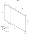
- a display device head 300 may include a first long side LS1, a second long side LS2 opposite the first long side LS1, a first short side SS1 adjacent to the first long side LS1 and the second long side LS2, and a second short side SS2 opposite the first short side SS1.
- the first short side area SS1 of the display device head 300 may be referred to as a first side area
- the second short side area SS2 of the display device head 300 may be referred to as a second side area opposite the first side area
- the first long side area LS1 of the display device head 300 may be referred to as a third side area adjacent to the first side area and the second side area and located between the first side area and the second side area
- the second long side area LS2 of the display device head 300 may be referred to as a fourth side area adjacent to the first side area and the second side area, located between the first side area and the second side area, and opposite the third side area.
- each of the first and second long sides LS1 and LS2 is shown and described as being greater than the length of each of the first and second short sides SS1 and SS2 for convenience of description, the length of each of the first and second long sides LS1 and LS2 may be approximately equal to the length of each of the first and second short sides SS1 and SS2.
- a first direction DR1 may be a direction parallel to the long sides LS1 and LS2 of a display panel 110
- a second direction DR2 may be a direction parallel to the short sides SS1 and SS2 of the display panel 110.
- a third direction DR3 may be a direction perpendicular to the first direction DR1 and/or the second direction DR2.
- the side of the display device head 300 at which an image is displayed may be referred to as a front or a front surface.
- the side of the display device head 300 at which an image is not observed when the display device head 300 displays the image may be referred to as a rear or a rear surface.
- the first long side portion LS1 may be referred to as an upper side or an upper surface
- the second long side portion LS2 may be referred to as a lower side or a lower surface.
- the first short side portion SS1 may be referred to as a right side or a right surface
- the second short side portion SS2 may be referred to as a left side or a left surface.
- the first long side LS1, the second long side LS2, the first short side SS1, and the second short side SS2 may be referred to as edges of the display device head 300.
- the points at which the first long side LS1, the second long side LS2, the first short side SS1, and the second short side SS2 join may be referred to as corners.
- the point at which the first long side LS1 and the first short side SS1 join may be referred to as a first corner C1
- the point at which the first long side LS1 and the second short side SS2 join may be referred to as a second corner C2
- the point at which the second short side SS2 and the second long side LS2 join may be referred to as a third corner C3
- the point at which the second long side LS2 and the first short side SS1 join may be referred to as a fourth corner C4.
- the direction from the first short side SS1 to the second short side SS2 or the direction from the second short side SS2 to the first short side SS1 may be referred to as a leftward-rightward direction LR or a horizontal direction DR1.
- the direction from the first long side LS1 to the second long side LS2 or the direction from the second long side LS2 to the first long side LS1 may be referred to as an upward-downward direction UD or a vertical direction DR2.
- the forward-rearward direction DR3 may be a direction perpendicular to the leftward-rightward direction LR and/or the upward-downward direction UD.
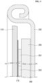
- the display device head 300 may include a display panel 110, a main frame 330, and an inner plate 350.
Landscapes
- Engineering & Computer Science (AREA)
- Physics & Mathematics (AREA)
- Multimedia (AREA)
- Signal Processing (AREA)
- Microelectronics & Electronic Packaging (AREA)
- Theoretical Computer Science (AREA)
- Thermal Sciences (AREA)
- Human Computer Interaction (AREA)
- General Engineering & Computer Science (AREA)
- General Physics & Mathematics (AREA)
- Cooling Or The Like Of Electrical Apparatus (AREA)
Claims (13)
- Steuergerät (200), umfassend:ein Gehäuse (201), das einen inneren Aufnahmeraum bereitstellt, wobei das Gehäuse eine in seiner oberen Fläche ausgebildete Öffnung aufweist;eine erste Platte (210), die von einer unteren Fläche des Gehäuses getragen wird;eine zweite Platte (220), die auf der ersten Platte angeordnet ist, wobei die zweite Platte von der ersten Platte beabstandet ist;eine dritte Platte (230), die auf der zweiten Platte angeordnet ist, wobei die dritte Platte von der zweiten Platte beabstandet ist;einen Drehteller (203), der die Öffnung abdeckt, wobei der Drehteller drehbar an der dritten Platte angebracht ist; undeinen Sender-Empfänger (250), der sich im Inneren des Gehäuses befindet, wobei der Sender-Empfänger mit dem Drehteller gekoppelt ist.
- Steuergerät nach Anspruch 1, wobei der Sender-Empfänger schwenkbar mit dem Drehteller verbunden ist.
- Steuergerät nach Anspruch 1 oder 2, wobei der Sender-Empfänger umfasst:eine Wärmesenke; undmindestens eine auf der Wärmesenke montierte Antenne, wobei die Wärmesenke umfasst:einen vorderen Teil, an dem die mindestens eine Antenne angebracht werden soll;einen hinteren Teil, der dem vorderen Teil zugewandt ist, wobei der hintere Teil von dem vorderen Teil beabstandet ist;einen oberen Teil, das eine Oberseite des vorderen Teils und eine Oberseite des hinteren Teils verbindet;einen unteren Teil, das eine untere Seite des vorderen Teils und eine untere Seite des hinteren Teils verbindet; undmindestens eine Rippe, die sich zwischen dem oberen Teil und dem unteren Teil befindet, wobei die mindestens eine Rippe so verläuft, dass sie den vorderen Teil und den hinteren Teil verbindet.
- Steuergerät nach Anspruch 3, wobei eine Dicke der mindestens einen Rippe kleiner ist als eine Dicke des vorderen Teils, eine Dicke des hinteren Teils, eine Dicke des oberen Teils und/oder eine Dicke des unteren Teils.
- Steuergerät nach Anspruch 3 oder 4, wobei der Sender-Empfänger ferner umfasst:
ein Kühlgebläse, das mit einer Seite der Wärmesenke verbunden ist. - Steuergerät nach einem der Ansprüche 1 bis 5, ferner umfassend:ein Gebläse, das mit einer Oberseite der dritten Platte verbunden ist; undeinen Stoßdämpfer, der sich zwischen dem Gebläse und der dritten Platte befindet.
- Steuergerät nach Anspruch 6, wobei das Gebläse umfasst:einen Einlass, der in einer dem Stoßdämpfer zugewandten Oberfläche ausgebildet ist;ein Gehäuse, das einen Strömungskanal für durch den Einlass eingeleitete Luft aufweist; undeinen Auslass, der in einer Seite des Gehäuses ausgebildet ist,wobei der Stoßdämpfer einen Durchflusskanal aufweist, der mit dem Einlass des Gebläses in Verbindung steht, undwobei die dritte Platte eine Öffnung aufweist, die mit dem Durchflusskanal im Stoßdämpfer in Verbindung steht.
- Steuergerät nach Anspruch 7, ferner umfassend:eine Auslassführung, die sich am Außenumfang des Auslasses des Gebläses befindet,wobei die Auslassführung umfasst:einen ersten Teil, der sich entlang einer oberen Kante des Auslasses erstreckt, wobei der erste Teil neben der oberen Kante des Auslasses angeordnet ist;einen zweiten Teil, der gebogen ist und sich von einem Ende des ersten Teils aus erstreckt, wobei der zweite Teil neben einer Seitenkante des Auslasses angeordnet ist; undeinen dritten Teil, der gebogen ist und sich von einem gegenüberliegenden Ende des ersten Teils aus erstreckt, wobei der dritte Teil neben einer gegenüberliegenden Seitenkante des Auslasses angeordnet ist.
- Steuergerät nach Anspruch 8, wobei das Gehäuse ferner umfasst:eine Auslassöffnung, die in einer Oberfläche des Gehäuses ausgebildet ist, wobei die Auslassöffnung dem Auslass des Gebläses zugewandt ist, undwobei sich die Auslassführung zwischen der Auslassöffnung und dem Auslass des Gebläses befindet.
- Steuergerät nach Anspruch 9, wobei das Gehäuse ferner umfasst:
mindestens eine Einlassöffnung, die in einer anderen Oberfläche des Gehäuses ausgebildet ist. - Steuergerät nach Anspruch 10, wobei die Auslassöffnung näher an einer oberen Fläche des Gehäuses angeordnet ist als die mindestens eine Einlassöffnung.
- Steuergerät nach einem der Ansprüche 1 bis 11, ferner umfassend:eine Stromversorgung, die zwischen der ersten und der zweiten Platte angeordnet ist, wobei die Stromversorgung auf der ersten Platte angebracht ist; undeine Hauptplatine, die sich zwischen der zweiten und der dritten Platte befindet, wobei die Hauptplatine auf der zweiten Platte angebracht ist.
- Steuergerät nach einem der Ansprüche 1 bis 12, ferner umfassend:
eine Isolierschicht, die eine obere Fläche der ersten Platte bedeckt.
Applications Claiming Priority (1)
| Application Number | Priority Date | Filing Date | Title |
|---|---|---|---|
| PCT/KR2021/000086 WO2022149624A1 (ko) | 2021-01-05 | 2021-01-05 | 제어박스 및 이를 구비하는 디스플레이 디바이스 |
Publications (2)
| Publication Number | Publication Date |
|---|---|
| EP4024852A1 EP4024852A1 (de) | 2022-07-06 |
| EP4024852B1 true EP4024852B1 (de) | 2025-03-12 |
Family
ID=77543290
Family Applications (1)
| Application Number | Title | Priority Date | Filing Date |
|---|---|---|---|
| EP21190300.0A Active EP4024852B1 (de) | 2021-01-05 | 2021-08-09 | Steuerungskasten |
Country Status (4)
| Country | Link |
|---|---|
| US (2) | US11864332B2 (de) |
| EP (1) | EP4024852B1 (de) |
| KR (1) | KR102726336B1 (de) |
| WO (1) | WO2022149624A1 (de) |
Families Citing this family (6)
| Publication number | Priority date | Publication date | Assignee | Title |
|---|---|---|---|---|
| KR102726336B1 (ko) | 2021-01-05 | 2024-11-04 | 엘지전자 주식회사 | 제어박스 및 이를 구비하는 디스플레이 디바이스 |
| US20240332782A1 (en) * | 2021-07-09 | 2024-10-03 | Lg Electronics Inc. | Display device |
| KR20250079176A (ko) * | 2022-10-05 | 2025-06-04 | 엘지전자 주식회사 | 제어박스 및 이를 구비하는 디스플레이 디바이스 |
| WO2024237368A1 (ko) * | 2023-05-17 | 2024-11-21 | 엘지전자 주식회사 | 제어박스 및 이를 구비하는 디스플레이 디바이스 |
| WO2026054134A1 (ko) * | 2024-09-05 | 2026-03-12 | 엘지전자 주식회사 | 제어 박스 및 이를 구비하는 디스플레이 디바이스 |
| WO2026071300A1 (ko) * | 2024-09-30 | 2026-04-02 | 엘지전자 주식회사 | 제어 박스 및 이를 구비하는 디스플레이 디바이스 |
Family Cites Families (23)
| Publication number | Priority date | Publication date | Assignee | Title |
|---|---|---|---|---|
| JP2902407B2 (ja) * | 1989-03-24 | 1999-06-07 | 新日本製鐵株式会社 | アンテナ装置 |
| ES2019505A6 (es) * | 1989-11-29 | 1991-06-16 | Sel Electronica Soc Coop S R L | Antena interior para la recepcion de senales televisivas |
| US6532152B1 (en) * | 1998-11-16 | 2003-03-11 | Intermec Ip Corp. | Ruggedized hand held computer |
| ES1050058Y (es) * | 2001-09-14 | 2002-06-16 | Televes Sa | Antena |
| US7055160B1 (en) * | 2002-12-20 | 2006-05-30 | Apple Computer, Inc. | Bezel door for computer enclosure |
| US7795553B2 (en) * | 2006-09-11 | 2010-09-14 | Apple Inc. | Hybrid button |
| US8023261B2 (en) * | 2008-09-05 | 2011-09-20 | Apple Inc. | Electronic device assembly |
| US9184546B2 (en) * | 2009-09-25 | 2015-11-10 | Pucline, Llc | Electrical power supplying device having a central power-hub assembly supplying electrical power to power plugs, adaptors and modules while concealed from view and managing excess power cord during power supplying operations |
| US8213164B2 (en) * | 2010-03-04 | 2012-07-03 | Jamal Benbrahim | Quick mounting system and media for video recording |
| US8432679B2 (en) * | 2010-06-15 | 2013-04-30 | Apple Inc. | Silicone barrier for drive window |
| US9407130B2 (en) * | 2010-11-10 | 2016-08-02 | Orsi R. Garcia | Wireless massage, heating and lift system |
| US8387763B2 (en) * | 2010-11-22 | 2013-03-05 | Telefonix, Inc. | Retractable cord reel |
| JP6124438B2 (ja) * | 2012-11-22 | 2017-05-10 | 古野電気株式会社 | レーダアンテナ、及びこれを備えたレーダ装置 |
| US9513682B2 (en) * | 2013-07-03 | 2016-12-06 | Pucline, Llc | Transportable electrical power supplying device for storing and configuring excess power cord and sharing a multiplicity of AC and DC electrical power supplies in diverse user environments |
| KR20160086334A (ko) * | 2013-11-13 | 2016-07-19 | 톰슨 라이센싱 | 인쇄 회로 기판에 대한 히트싱크 정렬 |
| US10718339B2 (en) * | 2015-09-03 | 2020-07-21 | Apple Inc. | Peripheral drive centrifugal fan |
| US10749308B2 (en) * | 2016-10-17 | 2020-08-18 | Waymo Llc | Thermal rotary link |
| KR102489874B1 (ko) * | 2017-11-24 | 2023-01-18 | 삼성전자주식회사 | 방열 구조를 포함하는 전자 장치 |
| US10795494B2 (en) * | 2018-01-03 | 2020-10-06 | Grayhill, Inc. | Touch encoder, touch panel, and input method editor with integrated development environment and methods thereof |
| KR102469449B1 (ko) * | 2018-02-09 | 2022-11-22 | 삼성전자주식회사 | 방열 구조 및 이를 포함하는 전자 장치 |
| KR20200007183A (ko) * | 2018-07-12 | 2020-01-22 | (주)더비트 | 디지털 음원의 재생 장치 |
| CN115380637A (zh) * | 2020-03-06 | 2022-11-22 | 奈特卡姆无线私人有限公司 | 具有改进的热负荷管理的电信壳体 |
| KR102726336B1 (ko) | 2021-01-05 | 2024-11-04 | 엘지전자 주식회사 | 제어박스 및 이를 구비하는 디스플레이 디바이스 |
-
2021
- 2021-01-05 KR KR1020237016497A patent/KR102726336B1/ko active Active
- 2021-01-05 WO PCT/KR2021/000086 patent/WO2022149624A1/ko not_active Ceased
- 2021-08-09 EP EP21190300.0A patent/EP4024852B1/de active Active
- 2021-08-10 US US17/444,782 patent/US11864332B2/en active Active
-
2023
- 2023-11-16 US US18/511,207 patent/US12207421B2/en active Active
Also Published As
| Publication number | Publication date |
|---|---|
| US20220217855A1 (en) | 2022-07-07 |
| KR102726336B1 (ko) | 2024-11-04 |
| US12207421B2 (en) | 2025-01-21 |
| EP4024852A1 (de) | 2022-07-06 |
| US11864332B2 (en) | 2024-01-02 |
| KR20230093452A (ko) | 2023-06-27 |
| WO2022149624A1 (ko) | 2022-07-14 |
| US20240090144A1 (en) | 2024-03-14 |
Similar Documents
| Publication | Publication Date | Title |
|---|---|---|
| US12207421B2 (en) | Control box and display device including the same | |
| US10306781B2 (en) | Control unit and display device comprising the same | |
| USRE45117E1 (en) | Panel type display device | |
| KR102099255B1 (ko) | 방열장치 및 이를 구비한 전자장치 | |
| US9232171B2 (en) | Electronic apparatus with cooling unit | |
| EP3425477A1 (de) | Anzeigevorrichtung | |
| US10390445B2 (en) | Display device | |
| US20050259401A1 (en) | Plasma display device | |
| CN115249444A (zh) | 显示装置 | |
| US8184434B2 (en) | Video/audio computer display processor | |
| US20170303422A1 (en) | Display device | |
| KR20170007655A (ko) | 표시 장치 | |
| KR102532474B1 (ko) | 제어박스 및 이를 구비하는 디스플레이 디바이스 | |
| KR20210009716A (ko) | 디스플레이 디바이스 | |
| US10390446B2 (en) | Display device | |
| KR102532473B1 (ko) | 제어박스 및 이를 구비하는 디스플레이 디바이스 | |
| TWI852005B (zh) | 電子裝置 | |
| US20060126300A1 (en) | Device for decreasing the temperature from address IC of plasma display panel and the method thereof | |
| US10260525B2 (en) | Fan module | |
| US7477016B2 (en) | Plasma display device capable of increasing attachment of heat-dissipating plate to plasma display panel | |
| US10481647B2 (en) | Computer system including a computer housing with a fastening device | |
| US20150111483A1 (en) | Server cabinet | |
| CN101969754B (zh) | 冷却装置 | |
| JP2007281214A (ja) | 冷却装置及びそれを備えた電子機器 | |
| JP2009162869A (ja) | プラズマディスプレイパネルモジュール及びプラズマディスプレイ装置 |
Legal Events
| Date | Code | Title | Description |
|---|---|---|---|
| PUAI | Public reference made under article 153(3) epc to a published international application that has entered the european phase |
Free format text: ORIGINAL CODE: 0009012 |
|
| STAA | Information on the status of an ep patent application or granted ep patent |
Free format text: STATUS: REQUEST FOR EXAMINATION WAS MADE |
|
| 17P | Request for examination filed |
Effective date: 20210809 |
|
| AK | Designated contracting states |
Kind code of ref document: A1 Designated state(s): AL AT BE BG CH CY CZ DE DK EE ES FI FR GB GR HR HU IE IS IT LI LT LU LV MC MK MT NL NO PL PT RO RS SE SI SK SM TR |
|
| GRAP | Despatch of communication of intention to grant a patent |
Free format text: ORIGINAL CODE: EPIDOSNIGR1 |
|
| STAA | Information on the status of an ep patent application or granted ep patent |
Free format text: STATUS: GRANT OF PATENT IS INTENDED |
|
| INTG | Intention to grant announced |
Effective date: 20241010 |
|
| GRAS | Grant fee paid |
Free format text: ORIGINAL CODE: EPIDOSNIGR3 |
|
| GRAA | (expected) grant |
Free format text: ORIGINAL CODE: 0009210 |
|
| STAA | Information on the status of an ep patent application or granted ep patent |
Free format text: STATUS: THE PATENT HAS BEEN GRANTED |
|
| AK | Designated contracting states |
Kind code of ref document: B1 Designated state(s): AL AT BE BG CH CY CZ DE DK EE ES FI FR GB GR HR HU IE IS IT LI LT LU LV MC MK MT NL NO PL PT RO RS SE SI SK SM TR |
|
| REG | Reference to a national code |
Ref country code: GB Ref legal event code: FG4D |
|
| REG | Reference to a national code |
Ref country code: CH Ref legal event code: EP |
|
| REG | Reference to a national code |
Ref country code: DE Ref legal event code: R096 Ref document number: 602021027414 Country of ref document: DE |
|
| REG | Reference to a national code |
Ref country code: IE Ref legal event code: FG4D |
|
| PG25 | Lapsed in a contracting state [announced via postgrant information from national office to epo] |
Ref country code: RS Free format text: LAPSE BECAUSE OF FAILURE TO SUBMIT A TRANSLATION OF THE DESCRIPTION OR TO PAY THE FEE WITHIN THE PRESCRIBED TIME-LIMIT Effective date: 20250612 |
|
| PG25 | Lapsed in a contracting state [announced via postgrant information from national office to epo] |
Ref country code: FI Free format text: LAPSE BECAUSE OF FAILURE TO SUBMIT A TRANSLATION OF THE DESCRIPTION OR TO PAY THE FEE WITHIN THE PRESCRIBED TIME-LIMIT Effective date: 20250312 |
|
| PG25 | Lapsed in a contracting state [announced via postgrant information from national office to epo] |
Ref country code: ES Free format text: LAPSE BECAUSE OF FAILURE TO SUBMIT A TRANSLATION OF THE DESCRIPTION OR TO PAY THE FEE WITHIN THE PRESCRIBED TIME-LIMIT Effective date: 20250312 |
|
| REG | Reference to a national code |
Ref country code: LT Ref legal event code: MG9D |
|
| PG25 | Lapsed in a contracting state [announced via postgrant information from national office to epo] |
Ref country code: NO Free format text: LAPSE BECAUSE OF FAILURE TO SUBMIT A TRANSLATION OF THE DESCRIPTION OR TO PAY THE FEE WITHIN THE PRESCRIBED TIME-LIMIT Effective date: 20250612 |
|
| PG25 | Lapsed in a contracting state [announced via postgrant information from national office to epo] |
Ref country code: HR Free format text: LAPSE BECAUSE OF FAILURE TO SUBMIT A TRANSLATION OF THE DESCRIPTION OR TO PAY THE FEE WITHIN THE PRESCRIBED TIME-LIMIT Effective date: 20250312 |
|
| REG | Reference to a national code |
Ref country code: NL Ref legal event code: MP Effective date: 20250312 |
|
| PG25 | Lapsed in a contracting state [announced via postgrant information from national office to epo] |
Ref country code: LV Free format text: LAPSE BECAUSE OF FAILURE TO SUBMIT A TRANSLATION OF THE DESCRIPTION OR TO PAY THE FEE WITHIN THE PRESCRIBED TIME-LIMIT Effective date: 20250312 |
|
| PG25 | Lapsed in a contracting state [announced via postgrant information from national office to epo] |
Ref country code: GR Free format text: LAPSE BECAUSE OF FAILURE TO SUBMIT A TRANSLATION OF THE DESCRIPTION OR TO PAY THE FEE WITHIN THE PRESCRIBED TIME-LIMIT Effective date: 20250613 Ref country code: BG Free format text: LAPSE BECAUSE OF FAILURE TO SUBMIT A TRANSLATION OF THE DESCRIPTION OR TO PAY THE FEE WITHIN THE PRESCRIBED TIME-LIMIT Effective date: 20250312 |
|
| REG | Reference to a national code |
Ref country code: AT Ref legal event code: MK05 Ref document number: 1775997 Country of ref document: AT Kind code of ref document: T Effective date: 20250312 |
|
| PG25 | Lapsed in a contracting state [announced via postgrant information from national office to epo] |
Ref country code: NL Free format text: LAPSE BECAUSE OF FAILURE TO SUBMIT A TRANSLATION OF THE DESCRIPTION OR TO PAY THE FEE WITHIN THE PRESCRIBED TIME-LIMIT Effective date: 20250312 |
|
| PG25 | Lapsed in a contracting state [announced via postgrant information from national office to epo] |
Ref country code: SE Free format text: LAPSE BECAUSE OF FAILURE TO SUBMIT A TRANSLATION OF THE DESCRIPTION OR TO PAY THE FEE WITHIN THE PRESCRIBED TIME-LIMIT Effective date: 20250312 |
|
| PG25 | Lapsed in a contracting state [announced via postgrant information from national office to epo] |
Ref country code: SM Free format text: LAPSE BECAUSE OF FAILURE TO SUBMIT A TRANSLATION OF THE DESCRIPTION OR TO PAY THE FEE WITHIN THE PRESCRIBED TIME-LIMIT Effective date: 20250312 |
|
| PG25 | Lapsed in a contracting state [announced via postgrant information from national office to epo] |
Ref country code: PT Free format text: LAPSE BECAUSE OF FAILURE TO SUBMIT A TRANSLATION OF THE DESCRIPTION OR TO PAY THE FEE WITHIN THE PRESCRIBED TIME-LIMIT Effective date: 20250714 |
|
| PGFP | Annual fee paid to national office [announced via postgrant information from national office to epo] |
Ref country code: DE Payment date: 20250707 Year of fee payment: 5 |
|
| PG25 | Lapsed in a contracting state [announced via postgrant information from national office to epo] |
Ref country code: IT Free format text: LAPSE BECAUSE OF FAILURE TO SUBMIT A TRANSLATION OF THE DESCRIPTION OR TO PAY THE FEE WITHIN THE PRESCRIBED TIME-LIMIT Effective date: 20250312 Ref country code: PL Free format text: LAPSE BECAUSE OF FAILURE TO SUBMIT A TRANSLATION OF THE DESCRIPTION OR TO PAY THE FEE WITHIN THE PRESCRIBED TIME-LIMIT Effective date: 20250312 |
|
| PGFP | Annual fee paid to national office [announced via postgrant information from national office to epo] |
Ref country code: GB Payment date: 20250707 Year of fee payment: 5 |
|
| PG25 | Lapsed in a contracting state [announced via postgrant information from national office to epo] |
Ref country code: AT Free format text: LAPSE BECAUSE OF FAILURE TO SUBMIT A TRANSLATION OF THE DESCRIPTION OR TO PAY THE FEE WITHIN THE PRESCRIBED TIME-LIMIT Effective date: 20250312 |
|
| PGFP | Annual fee paid to national office [announced via postgrant information from national office to epo] |
Ref country code: FR Payment date: 20250715 Year of fee payment: 5 |
|
| PG25 | Lapsed in a contracting state [announced via postgrant information from national office to epo] |
Ref country code: CZ Free format text: LAPSE BECAUSE OF FAILURE TO SUBMIT A TRANSLATION OF THE DESCRIPTION OR TO PAY THE FEE WITHIN THE PRESCRIBED TIME-LIMIT Effective date: 20250312 Ref country code: EE Free format text: LAPSE BECAUSE OF FAILURE TO SUBMIT A TRANSLATION OF THE DESCRIPTION OR TO PAY THE FEE WITHIN THE PRESCRIBED TIME-LIMIT Effective date: 20250312 |
|
| PG25 | Lapsed in a contracting state [announced via postgrant information from national office to epo] |
Ref country code: RO Free format text: LAPSE BECAUSE OF FAILURE TO SUBMIT A TRANSLATION OF THE DESCRIPTION OR TO PAY THE FEE WITHIN THE PRESCRIBED TIME-LIMIT Effective date: 20250312 |
|
| PG25 | Lapsed in a contracting state [announced via postgrant information from national office to epo] |
Ref country code: SK Free format text: LAPSE BECAUSE OF FAILURE TO SUBMIT A TRANSLATION OF THE DESCRIPTION OR TO PAY THE FEE WITHIN THE PRESCRIBED TIME-LIMIT Effective date: 20250312 |
|
| PG25 | Lapsed in a contracting state [announced via postgrant information from national office to epo] |
Ref country code: IS Free format text: LAPSE BECAUSE OF FAILURE TO SUBMIT A TRANSLATION OF THE DESCRIPTION OR TO PAY THE FEE WITHIN THE PRESCRIBED TIME-LIMIT Effective date: 20250712 |
|
| REG | Reference to a national code |
Ref country code: DE Ref legal event code: R097 Ref document number: 602021027414 Country of ref document: DE |
|
| PG25 | Lapsed in a contracting state [announced via postgrant information from national office to epo] |
Ref country code: DK Free format text: LAPSE BECAUSE OF FAILURE TO SUBMIT A TRANSLATION OF THE DESCRIPTION OR TO PAY THE FEE WITHIN THE PRESCRIBED TIME-LIMIT Effective date: 20250312 |
|
| PLBE | No opposition filed within time limit |
Free format text: ORIGINAL CODE: 0009261 |
|
| STAA | Information on the status of an ep patent application or granted ep patent |
Free format text: STATUS: NO OPPOSITION FILED WITHIN TIME LIMIT |
|
| REG | Reference to a national code |
Ref country code: CH Ref legal event code: L10 Free format text: ST27 STATUS EVENT CODE: U-0-0-L10-L00 (AS PROVIDED BY THE NATIONAL OFFICE) Effective date: 20260121 |
|
| 26N | No opposition filed |
Effective date: 20251215 |
|
| REG | Reference to a national code |
Ref country code: CH Ref legal event code: H13 Free format text: ST27 STATUS EVENT CODE: U-0-0-H10-H13 (AS PROVIDED BY THE NATIONAL OFFICE) Effective date: 20260324 |
|
| PG25 | Lapsed in a contracting state [announced via postgrant information from national office to epo] |
Ref country code: MC Free format text: LAPSE BECAUSE OF FAILURE TO SUBMIT A TRANSLATION OF THE DESCRIPTION OR TO PAY THE FEE WITHIN THE PRESCRIBED TIME-LIMIT Effective date: 20250312 |
|
| PG25 | Lapsed in a contracting state [announced via postgrant information from national office to epo] |
Ref country code: LU Free format text: LAPSE BECAUSE OF NON-PAYMENT OF DUE FEES Effective date: 20250809 |
|
| PG25 | Lapsed in a contracting state [announced via postgrant information from national office to epo] |
Ref country code: CH Free format text: LAPSE BECAUSE OF NON-PAYMENT OF DUE FEES Effective date: 20250831 |