EP4024638A1 - Apparatus for the generation, the distribution and/or the usage of electrical energy and method for coating at least one part of the same - Google Patents
Apparatus for the generation, the distribution and/or the usage of electrical energy and method for coating at least one part of the same Download PDFInfo
- Publication number
- EP4024638A1 EP4024638A1 EP20217980.0A EP20217980A EP4024638A1 EP 4024638 A1 EP4024638 A1 EP 4024638A1 EP 20217980 A EP20217980 A EP 20217980A EP 4024638 A1 EP4024638 A1 EP 4024638A1
- Authority
- EP
- European Patent Office
- Prior art keywords
- coating
- precursor
- flange
- gas
- distribution
- Prior art date
- Legal status (The legal status is an assumption and is not a legal conclusion. Google has not performed a legal analysis and makes no representation as to the accuracy of the status listed.)
- Pending
Links
- 238000000576 coating method Methods 0.000 title claims abstract description 34
- 238000000034 method Methods 0.000 title claims abstract description 28
- 239000011248 coating agent Substances 0.000 title claims abstract description 27
- 239000002243 precursor Substances 0.000 claims abstract description 26
- 229920000642 polymer Polymers 0.000 claims abstract description 14
- 238000007789 sealing Methods 0.000 claims description 14
- UQEAIHBTYFGYIE-UHFFFAOYSA-N hexamethyldisiloxane Polymers C[Si](C)(C)O[Si](C)(C)C UQEAIHBTYFGYIE-UHFFFAOYSA-N 0.000 claims description 11
- 230000002209 hydrophobic effect Effects 0.000 claims description 5
- SFZCNBIFKDRMGX-UHFFFAOYSA-N sulfur hexafluoride Chemical compound FS(F)(F)(F)(F)F SFZCNBIFKDRMGX-UHFFFAOYSA-N 0.000 claims description 4
- 238000004140 cleaning Methods 0.000 claims description 3
- 230000000379 polymerizing effect Effects 0.000 claims description 3
- 230000003213 activating effect Effects 0.000 claims description 2
- 239000007789 gas Substances 0.000 description 24
- 239000004205 dimethyl polysiloxane Substances 0.000 description 12
- 229920000435 poly(dimethylsiloxane) Polymers 0.000 description 12
- 230000008569 process Effects 0.000 description 11
- IJGRMHOSHXDMSA-UHFFFAOYSA-N Atomic nitrogen Chemical compound N#N IJGRMHOSHXDMSA-UHFFFAOYSA-N 0.000 description 6
- 238000012360 testing method Methods 0.000 description 6
- XAGFODPZIPBFFR-UHFFFAOYSA-N aluminium Chemical compound [Al] XAGFODPZIPBFFR-UHFFFAOYSA-N 0.000 description 4
- 229910052782 aluminium Inorganic materials 0.000 description 4
- 238000009413 insulation Methods 0.000 description 4
- 238000005259 measurement Methods 0.000 description 4
- 239000000700 radioactive tracer Substances 0.000 description 4
- -1 Polydimethylsiloxane Polymers 0.000 description 3
- YXFVVABEGXRONW-UHFFFAOYSA-N Toluene Chemical compound CC1=CC=CC=C1 YXFVVABEGXRONW-UHFFFAOYSA-N 0.000 description 3
- QVGXLLKOCUKJST-UHFFFAOYSA-N atomic oxygen Chemical compound [O] QVGXLLKOCUKJST-UHFFFAOYSA-N 0.000 description 3
- 238000010586 diagram Methods 0.000 description 3
- 239000000203 mixture Substances 0.000 description 3
- 229910052757 nitrogen Inorganic materials 0.000 description 3
- 239000001301 oxygen Substances 0.000 description 3
- 229910052760 oxygen Inorganic materials 0.000 description 3
- 239000002245 particle Substances 0.000 description 3
- CSCPPACGZOOCGX-UHFFFAOYSA-N Acetone Chemical compound CC(C)=O CSCPPACGZOOCGX-UHFFFAOYSA-N 0.000 description 2
- QGZKDVFQNNGYKY-UHFFFAOYSA-N Ammonia Chemical compound N QGZKDVFQNNGYKY-UHFFFAOYSA-N 0.000 description 2
- JUJWROOIHBZHMG-UHFFFAOYSA-N Pyridine Chemical compound C1=CC=NC=C1 JUJWROOIHBZHMG-UHFFFAOYSA-N 0.000 description 2
- KAESVJOAVNADME-UHFFFAOYSA-N Pyrrole Chemical compound C=1C=CNC=1 KAESVJOAVNADME-UHFFFAOYSA-N 0.000 description 2
- BOTDANWDWHJENH-UHFFFAOYSA-N Tetraethyl orthosilicate Chemical compound CCO[Si](OCC)(OCC)OCC BOTDANWDWHJENH-UHFFFAOYSA-N 0.000 description 2
- YTPLMLYBLZKORZ-UHFFFAOYSA-N Thiophene Chemical compound C=1C=CSC=1 YTPLMLYBLZKORZ-UHFFFAOYSA-N 0.000 description 2
- 230000005540 biological transmission Effects 0.000 description 2
- 230000007797 corrosion Effects 0.000 description 2
- 238000005260 corrosion Methods 0.000 description 2
- 239000012212 insulator Substances 0.000 description 2
- 239000008213 purified water Substances 0.000 description 2
- XLYOFNOQVPJJNP-UHFFFAOYSA-N water Chemical compound O XLYOFNOQVPJJNP-UHFFFAOYSA-N 0.000 description 2
- WRIDQFICGBMAFQ-UHFFFAOYSA-N (E)-8-Octadecenoic acid Natural products CCCCCCCCCC=CCCCCCCC(O)=O WRIDQFICGBMAFQ-UHFFFAOYSA-N 0.000 description 1
- RIQRGMUSBYGDBL-UHFFFAOYSA-N 1,1,1,2,2,3,4,5,5,5-decafluoropentane Chemical compound FC(F)(F)C(F)C(F)C(F)(F)C(F)(F)F RIQRGMUSBYGDBL-UHFFFAOYSA-N 0.000 description 1
- AZQWKYJCGOJGHM-UHFFFAOYSA-N 1,4-benzoquinone Chemical compound O=C1C=CC(=O)C=C1 AZQWKYJCGOJGHM-UHFFFAOYSA-N 0.000 description 1
- SMZOUWXMTYCWNB-UHFFFAOYSA-N 2-(2-methoxy-5-methylphenyl)ethanamine Chemical compound COC1=CC=C(C)C=C1CCN SMZOUWXMTYCWNB-UHFFFAOYSA-N 0.000 description 1
- NIXOWILDQLNWCW-UHFFFAOYSA-N 2-Propenoic acid Natural products OC(=O)C=C NIXOWILDQLNWCW-UHFFFAOYSA-N 0.000 description 1
- LQJBNNIYVWPHFW-UHFFFAOYSA-N 20:1omega9c fatty acid Natural products CCCCCCCCCCC=CCCCCCCCC(O)=O LQJBNNIYVWPHFW-UHFFFAOYSA-N 0.000 description 1
- QSBYPNXLFMSGKH-UHFFFAOYSA-N 9-Heptadecensaeure Natural products CCCCCCCC=CCCCCCCCC(O)=O QSBYPNXLFMSGKH-UHFFFAOYSA-N 0.000 description 1
- 229920001661 Chitosan Polymers 0.000 description 1
- XDTMQSROBMDMFD-UHFFFAOYSA-N Cyclohexane Chemical compound C1CCCCC1 XDTMQSROBMDMFD-UHFFFAOYSA-N 0.000 description 1
- RWSOTUBLDIXVET-UHFFFAOYSA-N Dihydrogen sulfide Chemical compound S RWSOTUBLDIXVET-UHFFFAOYSA-N 0.000 description 1
- MYMOFIZGZYHOMD-UHFFFAOYSA-N Dioxygen Chemical compound O=O MYMOFIZGZYHOMD-UHFFFAOYSA-N 0.000 description 1
- OYHQOLUKZRVURQ-HZJYTTRNSA-N Linoleic acid Chemical compound CCCCC\C=C/C\C=C/CCCCCCCC(O)=O OYHQOLUKZRVURQ-HZJYTTRNSA-N 0.000 description 1
- CERQOIWHTDAKMF-UHFFFAOYSA-N Methacrylic acid Chemical compound CC(=C)C(O)=O CERQOIWHTDAKMF-UHFFFAOYSA-N 0.000 description 1
- VVQNEPGJFQJSBK-UHFFFAOYSA-N Methyl methacrylate Chemical compound COC(=O)C(C)=C VVQNEPGJFQJSBK-UHFFFAOYSA-N 0.000 description 1
- 239000005642 Oleic acid Substances 0.000 description 1
- ZQPPMHVWECSIRJ-UHFFFAOYSA-N Oleic acid Natural products CCCCCCCCC=CCCCCCCCC(O)=O ZQPPMHVWECSIRJ-UHFFFAOYSA-N 0.000 description 1
- OFOBLEOULBTSOW-UHFFFAOYSA-N Propanedioic acid Natural products OC(=O)CC(O)=O OFOBLEOULBTSOW-UHFFFAOYSA-N 0.000 description 1
- NINIDFKCEFEMDL-UHFFFAOYSA-N Sulfur Chemical compound [S] NINIDFKCEFEMDL-UHFFFAOYSA-N 0.000 description 1
- 239000005864 Sulphur Substances 0.000 description 1
- 230000004913 activation Effects 0.000 description 1
- HSFWRNGVRCDJHI-UHFFFAOYSA-N alpha-acetylene Natural products C#C HSFWRNGVRCDJHI-UHFFFAOYSA-N 0.000 description 1
- DTOSIQBPPRVQHS-PDBXOOCHSA-N alpha-linolenic acid Chemical compound CC\C=C/C\C=C/C\C=C/CCCCCCCC(O)=O DTOSIQBPPRVQHS-PDBXOOCHSA-N 0.000 description 1
- 235000020661 alpha-linolenic acid Nutrition 0.000 description 1
- 229910021529 ammonia Inorganic materials 0.000 description 1
- 230000008033 biological extinction Effects 0.000 description 1
- 239000003990 capacitor Substances 0.000 description 1
- 230000007547 defect Effects 0.000 description 1
- 230000001419 dependent effect Effects 0.000 description 1
- 238000013461 design Methods 0.000 description 1
- 239000003599 detergent Substances 0.000 description 1
- 125000002534 ethynyl group Chemical group [H]C#C* 0.000 description 1
- ZZUFCTLCJUWOSV-UHFFFAOYSA-N furosemide Chemical compound C1=C(Cl)C(S(=O)(=O)N)=CC(C(O)=O)=C1NCC1=CC=CO1 ZZUFCTLCJUWOSV-UHFFFAOYSA-N 0.000 description 1
- 210000004209 hair Anatomy 0.000 description 1
- FFUAGWLWBBFQJT-UHFFFAOYSA-N hexamethyldisilazane Chemical compound C[Si](C)(C)N[Si](C)(C)C FFUAGWLWBBFQJT-UHFFFAOYSA-N 0.000 description 1
- 239000001257 hydrogen Substances 0.000 description 1
- 229910052739 hydrogen Inorganic materials 0.000 description 1
- 125000004435 hydrogen atom Chemical class [H]* 0.000 description 1
- 230000010354 integration Effects 0.000 description 1
- QXJSBBXBKPUZAA-UHFFFAOYSA-N isooleic acid Natural products CCCCCCCC=CCCCCCCCCC(O)=O QXJSBBXBKPUZAA-UHFFFAOYSA-N 0.000 description 1
- 235000020778 linoleic acid Nutrition 0.000 description 1
- OYHQOLUKZRVURQ-IXWMQOLASA-N linoleic acid Natural products CCCCC\C=C/C\C=C\CCCCCCCC(O)=O OYHQOLUKZRVURQ-IXWMQOLASA-N 0.000 description 1
- 229960004488 linolenic acid Drugs 0.000 description 1
- KQQKGWQCNNTQJW-UHFFFAOYSA-N linolenic acid Natural products CC=CCCC=CCC=CCCCCCCCC(O)=O KQQKGWQCNNTQJW-UHFFFAOYSA-N 0.000 description 1
- 239000007788 liquid Substances 0.000 description 1
- VZCYOOQTPOCHFL-UPHRSURJSA-N maleic acid Chemical compound OC(=O)\C=C/C(O)=O VZCYOOQTPOCHFL-UPHRSURJSA-N 0.000 description 1
- 239000011976 maleic acid Substances 0.000 description 1
- 238000012986 modification Methods 0.000 description 1
- 230000004048 modification Effects 0.000 description 1
- 239000000178 monomer Substances 0.000 description 1
- ZQPPMHVWECSIRJ-KTKRTIGZSA-N oleic acid Chemical compound CCCCCCCC\C=C/CCCCCCCC(O)=O ZQPPMHVWECSIRJ-KTKRTIGZSA-N 0.000 description 1
- 235000021313 oleic acid Nutrition 0.000 description 1
- 229920000036 polyvinylpyrrolidone Polymers 0.000 description 1
- 235000013855 polyvinylpyrrolidone Nutrition 0.000 description 1
- 239000001267 polyvinylpyrrolidone Substances 0.000 description 1
- 238000010248 power generation Methods 0.000 description 1
- UMJSCPRVCHMLSP-UHFFFAOYSA-N pyridine Natural products COC1=CC=CN=C1 UMJSCPRVCHMLSP-UHFFFAOYSA-N 0.000 description 1
- 230000009467 reduction Effects 0.000 description 1
- 239000004065 semiconductor Substances 0.000 description 1
- 239000000126 substance Substances 0.000 description 1
- 238000009210 therapy by ultrasound Methods 0.000 description 1
- 229930192474 thiophene Natural products 0.000 description 1
- VZCYOOQTPOCHFL-UHFFFAOYSA-N trans-butenedioic acid Natural products OC(=O)C=CC(O)=O VZCYOOQTPOCHFL-UHFFFAOYSA-N 0.000 description 1
Images


Classifications
-
- H—ELECTRICITY
- H02—GENERATION; CONVERSION OR DISTRIBUTION OF ELECTRIC POWER
- H02G—INSTALLATION OF ELECTRIC CABLES OR LINES, OR OF COMBINED OPTICAL AND ELECTRIC CABLES OR LINES
- H02G5/00—Installations of bus-bars
- H02G5/06—Totally-enclosed installations, e.g. in metal casings
- H02G5/063—Totally-enclosed installations, e.g. in metal casings filled with oil or gas
-
- B—PERFORMING OPERATIONS; TRANSPORTING
- B29—WORKING OF PLASTICS; WORKING OF SUBSTANCES IN A PLASTIC STATE IN GENERAL
- B29C—SHAPING OR JOINING OF PLASTICS; SHAPING OF MATERIAL IN A PLASTIC STATE, NOT OTHERWISE PROVIDED FOR; AFTER-TREATMENT OF THE SHAPED PRODUCTS, e.g. REPAIRING
- B29C70/00—Shaping composites, i.e. plastics material comprising reinforcements, fillers or preformed parts, e.g. inserts
-
- H—ELECTRICITY
- H01—ELECTRIC ELEMENTS
- H01H—ELECTRIC SWITCHES; RELAYS; SELECTORS; EMERGENCY PROTECTIVE DEVICES
- H01H33/00—High-tension or heavy-current switches with arc-extinguishing or arc-preventing means
- H01H33/02—Details
- H01H33/53—Cases; Reservoirs, tanks, piping or valves, for arc-extinguishing fluid; Accessories therefor, e.g. safety arrangements, pressure relief devices
- H01H33/56—Gas reservoirs
-
- H—ELECTRICITY
- H02—GENERATION; CONVERSION OR DISTRIBUTION OF ELECTRIC POWER
- H02B—BOARDS, SUBSTATIONS OR SWITCHING ARRANGEMENTS FOR THE SUPPLY OR DISTRIBUTION OF ELECTRIC POWER
- H02B13/00—Arrangement of switchgear in which switches are enclosed in, or structurally associated with, a casing, e.g. cubicle
- H02B13/02—Arrangement of switchgear in which switches are enclosed in, or structurally associated with, a casing, e.g. cubicle with metal casing
- H02B13/035—Gas-insulated switchgear
- H02B13/045—Details of casing, e.g. gas tightness
-
- B—PERFORMING OPERATIONS; TRANSPORTING
- B05—SPRAYING OR ATOMISING IN GENERAL; APPLYING FLUENT MATERIALS TO SURFACES, IN GENERAL
- B05D—PROCESSES FOR APPLYING FLUENT MATERIALS TO SURFACES, IN GENERAL
- B05D1/00—Processes for applying liquids or other fluent materials
- B05D1/62—Plasma-deposition of organic layers
-
- H—ELECTRICITY
- H01—ELECTRIC ELEMENTS
- H01H—ELECTRIC SWITCHES; RELAYS; SELECTORS; EMERGENCY PROTECTIVE DEVICES
- H01H33/00—High-tension or heavy-current switches with arc-extinguishing or arc-preventing means
- H01H33/60—Switches wherein the means for extinguishing or preventing the arc do not include separate means for obtaining or increasing flow of arc-extinguishing fluid
- H01H33/66—Vacuum switches
- H01H33/662—Housings or protective screens
- H01H33/66207—Specific housing details, e.g. sealing, soldering or brazing
- H01H2033/6623—Details relating to the encasing or the outside layers of the vacuum switch housings
Definitions
- the present application relates to an apparatus for the generation, the distribution and/or the usage of electrical energy and a method for coating at least one part of the same.
- Dielectric insulation media in liquid or gaseous state are conventionally applied for the insulation of an electrical component in a wide variety of apparatuses, such as for example switchgears, gas-insulated substations, gas-insulated lines (GIL), or transformers.
- switchgears gas-insulated substations
- GIL gas-insulated lines
- the electrical component is arranged in a gas-tight housing, the interior of which defines an insulating space, said insulation space comprising an insulation gas and separating and electrically insulating the housing from the electrical component.
- the insulating gas further functions as an arc extinction gas.
- GIS Gas-insulated high-voltage switchgear
- high-voltage components such as circuit-breakers and disconnectors, which can be safely operated in confined spaces.
- GIS can be used where space is limited, for example, extensions, in city buildings, on roofs, on offshore platforms, industrial plants and hydro power plants. Due to its compact design GIS is ideal gear for power transmission, integration of renewable power generation units, e.g. distributed energy resources, to the grid or application in railway systems.
- the insulating gas typically sulphur hexaflouride (SF6)
- SF6 sulphur hexaflouride
- the sealing of these components is ensured using aluminum flanges with single or double O-rings which are greased for better outdoor corrosion protection.
- the present application relates to a method for coating at least one part of an apparatus for the generation, the distribution and/or the usage of electrical energy.
- the method comprises coating the at least one part of the apparatus with a polymer.
- the coating is made by applying a precursor in an atmospheric pressure plasma to the at least one part of the apparatus by and modifying the precursor with the atmospheric pressure plasma.
- the present application also relates to an apparatus for the generation, the distribution and/or the usage of electrical energy.
- the apparatus comprises at least one part which is coated with a polymer, wherein the coating has been made by applying a precursor in an atmospheric pressure plasma to the at least one part of the apparatus and modifying the precursor with the atmospheric pressure plasma.
- the apparatus is or comprises switchgear, in particular gas-insulated switchgear, live tank breakers, dead tank breakers, multifunctional modules, a busbar, a bushing, a cable, a gas-insulated cable, a cable joint, a gas-insulated line (GIL), a transformer, a current transformer, a voltage transformer, a surge arrester, an earthing switch, a disconnector, a combined disconnector and earthing switch, a load-break switch, a circuit breaker, any type of gas-insulated switch, a high voltage apparatus, a medium voltage apparatus, a low voltage apparatus, a direct-current apparatus, an air-insulated insulator, a gas-insulated metal-encapsulated insulator, sensors, a capacitor, an inductance, a resistor, a current limiter, a high voltage switch, a gas circuit breaker, a vacuum circuit breaker, a generator circuit breaker, a medium voltage switch, a ring main unit, a recloser, , a low voltage
- the apparatus is not limited to these preferred embodiments and the present application is also applicable to other apparatuses in the field of generation, distribution and/or usage of electrical energy.
- the apparatus is or comprises a high voltage apparatus, or is a high voltage component, respectively.
- the apparatus is gas-insulated, more preferably Sulfur-hexafluoride-, SF6-insulated.
- the method comprises cleaning and/or activating the at least one part and/or a surface thereof with the atmospheric pressure plasma before applying the precursor.
- the polymer is hydrophobic and viscoelastic.
- the surface characteristics may preferably be measured via contact angle measurement using a contact angle measuring device. Therefore, the samples may be placed into acetone then have ultrasonic treatment for approximately 15 minutes. After that, the samples may be taken out at room temperature for at least 1 hour. One or more drops of purified water may be dropped on the sample surface. The contact angle may be analyzed via a computer. The surface of the sample is hydrophobic when the contact angle of the drop of purified water on the sample surface is greater than 90°.
- the polymer is Polydimethylsiloxane (PDMS).
- the precursor is Hexamethyldisiloxane (HMDSO).
- the precursor is one of tetraethoxysilane (TEOS), hexamethyl-disilazane (HMDS), acetylene, maleic acid, oleic acid, linoleic acid and linolenic acid, acrylic acid, methacrylic acid, methacrylic acid methyl ester, pyrrole, pyridine, N-trimethyl chitosan, benzoquinone, polyvinylpyrrolidone, toluene, cyclohexane, decafluoropentane, and thiophene.
- TEOS tetraethoxysilane
- HMDS hexamethyl-disilazane
- acetylene maleic acid, oleic acid, linoleic acid and linolenic acid
- acrylic acid methacrylic acid, methacrylic acid methyl ester
- pyrrole pyridine
- N-trimethyl chitosan
- the plasma is generated in a process gas by a discharge in the process gas.
- the plasma is generated in a plasma nozzle.
- the process gas is nitrogen, oxygen, hydrogen, noble gasses, ammonia, hydrogen sulphide and mixtures thereof, in particular a mixture of oxygen and nitrogen or pure oxygen.
- the modifying is polymerizing of the precursor.
- the thickness of the coating is within the range of 150 to 500 nm.
- the thickness of the coating is within the range of 200 to 400 nm.
- the thickness of the coating is one of: 200 nm, 300 nm or 400 nm.
- the at least one part of the apparatus is a sealing surface.
- the at least one part of the apparatus is a flange, more preferably a contact face of the flange.
- the at least one part of the apparatus is configured to receive a sealing member.
- the sealing surface is a flange and the flange when being connected to a second flange, preferably through a sealing member, is gas-tight, more preferably Sulfur-hexafluoride-, SF6-,tight.
- Figure 1 shows a flowchart according to an embodiment of the present disclosure.
- a part of or the whole apparatus for the generation, the distribution and/or the usage of electrical energy e.g. a flange of a gas-insulated switchgear (GIS) is coated with a polymer.
- GIS gas-insulated switchgear
- a precursor and a process gas are injected into a nozzle and a plasma is generated in the process gas by a discharge between electrodes.
- a precursor is Hexamethyldisiloxane (HMDSO) and an example of the process gas is a mixture of nitrogen and oxygen.
- HMDSO Hexamethyldisiloxane
- the process gas is a mixture of nitrogen and oxygen.
- the particles of the precursor in the plasma and some of the plasma are then sprayed onto the surface to be coated, e.g. the surface of the flange.
- a second step S102 the precursor which is sprayed/applied to the flange, i.e. the HMDSO monomer, polymerizes thus forming long chains which are cross-linked thus forming a film of Polydimethylsiloxane (PDMS).
- the film of PDMS has a thickness of about 400 nm according to this embodiment but is not limited to.
- the coated polymer PDMS is very robust against most of the chemicals occurring in the field of the present applications, e.g. detergents for cleaning the apparatus for the generation, the distribution and/or the usage of electrical energy.
- PDMS is known to be hydrophobic and viscoelastic.
- PDMS is known for having self-healing properties. Minor scratches on the surface to be coated are recovered within a certain time, e.g. about 12h.
- PDMS has a high electrical resistance and is thus supposed to be electrically insulating.
- the connection shows a surprisingly low electric resistance and no bypass wires are needed to ensure electrical connection across flanges.
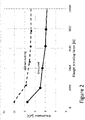
- Fig. 2 shows a comparison between a flange connection of bare Aluminum surface to a flange connection with two coated flanges.
- FIG. 3 shows a flow diagram according to another embodiment of the present disclosure.
- a part of or the whole apparatus for the generation, the distribution and/or the usage of electrical energy e.g. a flange of a gas-insulated switchgear (GIS) is coated with a polymer.
- GIS gas-insulated switchgear
- a first step S100 the (surface of the) flange is cleaned and activated with the atmospheric pressure plasma. Therefore, the process gas is injected into the nozzle and the plasma is generated in the process gas by a discharge between electrodes. The plasma is the directed onto the flange and the surface is activated and cleaned.
- This step is performed in case the object to be coated has to be activated and/cleaned and it is understood by the skilled person that this step might be omitted in case the surface is already sufficiently clean and/or no activation is needed.
- the second step S201 according to this embodiment is identical to the first step S101 according to the embodiment shown in Figure 1 .
- the precursor and the process gas are injected into the nozzle and the plasma is generated in the process gas by a discharge between electrodes.
- the particles of the precursor in the plasma and some of the plasma are then sprayed onto the object to be coated.
- the third step S202 according to this embodiment is identical to the second step S102 according to the embodiment shown in Figure 1 .
- the precursor which is sprayed/applied to the flange polymerizes thus forming long chains which are cross-linked leading to a film of PDMS.
- Figure 4 shows the SF6 leakage rate of a circuit breaker with uncoated flanges and of circuit breakers having coated flanges with coatings from 200 to 400 nm.
- SF6 has been used in all examples as a tracer gas.
- Table 1 shows a comparison between circuit breakers with coated flanges according to the present disclosure and a circuit breaker with uncoated flanges.
- the reference object is a reference circuit breaker with uncoated flanges and the test objects with 200 nm, 300 nm and 400 nm coating are circuit breakers having coated flanges with coatings from 200 to 400 nm, respectively.
- the obtained leakage rates of the circuit breaker with uncoated flanges and of the circuit breakers having coated flanges with coatings from 200 to 400 nm are plotted in Figure 4 .
- the reference object with bare aluminum flanges shows a leakage rate of 0.449 % per year whereas the leakage rate for the different coatings varies from 0,038 % per year for 400 nm coatings to 0.063 % per year for 200 nm coatings.
- a significant reduction of the leakage rate F can be achieved.
Abstract
Description
- The present application relates to an apparatus for the generation, the distribution and/or the usage of electrical energy and a method for coating at least one part of the same.
- Dielectric insulation media in liquid or gaseous state are conventionally applied for the insulation of an electrical component in a wide variety of apparatuses, such as for example switchgears, gas-insulated substations, gas-insulated lines (GIL), or transformers.
- In medium or high voltage metal-encapsulated switchgears, for example, the electrical component is arranged in a gas-tight housing, the interior of which defines an insulating space, said insulation space comprising an insulation gas and separating and electrically insulating the housing from the electrical component. For interrupting the current in a high voltage switchgear, the insulating gas further functions as an arc extinction gas.
- Gas-insulated high-voltage switchgear (GIS) is a compact encapsulated switchgear comprising high-voltage components such as circuit-breakers and disconnectors, which can be safely operated in confined spaces. GIS can be used where space is limited, for example, extensions, in city buildings, on roofs, on offshore platforms, industrial plants and hydro power plants. Due to its compact design GIS is ideal gear for power transmission, integration of renewable power generation units, e.g. distributed energy resources, to the grid or application in railway systems. In such switchgear the insulating gas, typically sulphur hexaflouride (SF6), is under high pressure up to 8 bar (absolute) and is normally sealed within the equipment and high demands are made with regard to the gas-tightness of the connections within the switchgear. Typically, the sealing of these components is ensured using aluminum flanges with single or double O-rings which are greased for better outdoor corrosion protection.
- However, a significant part of occurring defects in switchgear used for power transmission and distribution is caused by SF6 leakages, e.g. due to damaged sealing flanges (e.g. scratches), trapped dirt/particles/hairs at the O-ring(s) or corrosion processes. This does not only apply to gas-insulated switchgear but to all different kind of devices for the generation, the distribution and/or the usage of electrical energy, like (but not limited to) switchgear, medium/ high voltage switchgear, gas insulated switchgear, live tank breakers, dead tank breakers, multifunctional modules and generator circuit breakers. Thus, there is a need for reducing the occurring leakages in gas-insulated devices for the generation, the distribution and/or the usage of electrical energy.
- The aforementioned object, among others, is achieved by the independent claims. Dependent claims refer to preferred embodiments.
- The present application relates to a method for coating at least one part of an apparatus for the generation, the distribution and/or the usage of electrical energy. The method comprises coating the at least one part of the apparatus with a polymer. The coating is made by applying a precursor in an atmospheric pressure plasma to the at least one part of the apparatus by and modifying the precursor with the atmospheric pressure plasma.
- The present application also relates to an apparatus for the generation, the distribution and/or the usage of electrical energy.
- Various embodiments may preferably implement the following features:
Preferably, the apparatus comprises at least one part which is coated with a polymer, wherein the coating has been made by applying a precursor in an atmospheric pressure plasma to the at least one part of the apparatus and modifying the precursor with the atmospheric pressure plasma. - Preferably, the apparatus is or comprises switchgear, in particular gas-insulated switchgear, live tank breakers, dead tank breakers, multifunctional modules, a busbar, a bushing, a cable, a gas-insulated cable, a cable joint, a gas-insulated line (GIL), a transformer, a current transformer, a voltage transformer, a surge arrester, an earthing switch, a disconnector, a combined disconnector and earthing switch, a load-break switch, a circuit breaker, any type of gas-insulated switch, a high voltage apparatus, a medium voltage apparatus, a low voltage apparatus, a direct-current apparatus, an air-insulated insulator, a gas-insulated metal-encapsulated insulator, sensors, a capacitor, an inductance, a resistor, a current limiter, a high voltage switch, a gas circuit breaker, a vacuum circuit breaker, a generator circuit breaker, a medium voltage switch, a ring main unit, a recloser, , a low voltage switch, a distribution transformer, a power transformer, a tap changer, a transformer bushing, a power semiconductor device, a power converter, a converter station, and/or generator circuit breakers. However, it is understood by the skilled person that the apparatus is not limited to these preferred embodiments and the present application is also applicable to other apparatuses in the field of generation, distribution and/or usage of electrical energy. Preferably, the apparatus is or comprises a high voltage apparatus, or is a high voltage component, respectively.
- Preferably, the apparatus is gas-insulated, more preferably Sulfur-hexafluoride-, SF6-insulated.
- Preferably, the method comprises cleaning and/or activating the at least one part and/or a surface thereof with the atmospheric pressure plasma before applying the precursor.
- Preferably, the polymer is hydrophobic and viscoelastic.
- The surface characteristics, e.g. hydrophobicity may preferably be measured via contact angle measurement using a contact angle measuring device.
Therefore, the samples may be placed into acetone then have ultrasonic treatment for approximately 15 minutes. After that, the samples may be taken out at room temperature for at least 1 hour. One or more drops of purified water may be dropped on the sample surface. The contact angle may be analyzed via a computer.
The surface of the sample is hydrophobic when the contact angle of the drop of purified water on the sample surface is greater than 90°. - Preferably the polymer is Polydimethylsiloxane (PDMS).
- Preferably, the precursor is Hexamethyldisiloxane (HMDSO).
- Preferably, the precursor is one of tetraethoxysilane (TEOS), hexamethyl-disilazane (HMDS), acetylene, maleic acid, oleic acid, linoleic acid and linolenic acid, acrylic acid, methacrylic acid, methacrylic acid methyl ester, pyrrole, pyridine, N-trimethyl chitosan, benzoquinone, polyvinylpyrrolidone, toluene, cyclohexane, decafluoropentane, and thiophene.
- Preferably, the plasma is generated in a process gas by a discharge in the process gas. Preferably, the plasma is generated in a plasma nozzle. Preferably, the process gas is nitrogen, oxygen, hydrogen, noble gasses, ammonia, hydrogen sulphide and mixtures thereof, in particular a mixture of oxygen and nitrogen or pure oxygen.
- Preferably, the modifying is polymerizing of the precursor.
- Preferably, the thickness of the coating is within the range of 150 to 500 nm. Preferably, the thickness of the coating is within the range of 200 to 400 nm. Preferably, the thickness of the coating is one of: 200 nm, 300 nm or 400 nm.
- Preferably, the at least one part of the apparatus is a sealing surface. Preferably, the at least one part of the apparatus is a flange, more preferably a contact face of the flange.
- Preferably, the at least one part of the apparatus is configured to receive a sealing member.
- Preferably, the sealing surface is a flange and the flange when being connected to a second flange, preferably through a sealing member, is gas-tight, more preferably Sulfur-hexafluoride-, SF6-,tight.
- Various exemplary embodiments of the present disclosure are described in detail below with reference to the following Figures. The drawings are provided for purposes of illustration only and merely depict exemplary embodiments of the present disclosure to facilitate the reader's understanding of the present disclosure.
- Therefore, the drawings should not be considered limiting of the breadth, scope, or applicability of the present disclosure.
- It should be noted that for clarity and ease of illustration these drawings are not necessarily drawn to scale.
-
FIG. 1 shows a flow diagram according to an embodiment of the present disclosure. -
FIG. 2 shows a comparation between a flange connection of bare Aluminum surface to a flange connection with two coated flanges. -
FIG. 3 shows a flow diagram according to another embodiment of the present disclosure. -
FIG. 4 shows the SF6 leakage rate of a circuit breaker with uncoated flanges and of circuit breakers having coated flanges with coatings from 200 to 400 nm. -
Figure 1 shows a flowchart according to an embodiment of the present disclosure. According to this embodiment, a part of or the whole apparatus for the generation, the distribution and/or the usage of electrical energy, e.g. a flange of a gas-insulated switchgear (GIS) is coated with a polymer. - In a first step S101, a precursor and a process gas are injected into a nozzle and a plasma is generated in the process gas by a discharge between electrodes. An example of the precursor is Hexamethyldisiloxane (HMDSO) and an example of the process gas is a mixture of nitrogen and oxygen. The particles of the precursor in the plasma and some of the plasma are then sprayed onto the surface to be coated, e.g. the surface of the flange.
- In a second step S102, the precursor which is sprayed/applied to the flange, i.e. the HMDSO monomer, polymerizes thus forming long chains which are cross-linked thus forming a film of Polydimethylsiloxane (PDMS). The film of PDMS has a thickness of about 400 nm according to this embodiment but is not limited to.
- The coated polymer PDMS is very robust against most of the chemicals occurring in the field of the present applications, e.g. detergents for cleaning the apparatus for the generation, the distribution and/or the usage of electrical energy. PDMS is known to be hydrophobic and viscoelastic.
- Moreover, PDMS is known for having self-healing properties. Minor scratches on the surface to be coated are recovered within a certain time, e.g. about 12h.
- PDMS has a high electrical resistance and is thus supposed to be electrically insulating. However, when PDMS is applied to a flange of a GIS and said flange is connected to another flange having PDMS or not, the connection shows a surprisingly low electric resistance and no bypass wires are needed to ensure electrical connection across flanges.
-
Fig. 2 shows a comparison between a flange connection of bare Aluminum surface to a flange connection with two coated flanges. - It can be seen from
Figure 2 that the flange connection with two coated flanges having a coating of XXX with a thickness of 400 nm has still a surprisingly low electric resistance. -
FIG. 3 shows a flow diagram according to another embodiment of the present disclosure. According to this embodiment, a part of or the whole apparatus for the generation, the distribution and/or the usage of electrical energy, e.g. a flange of a gas-insulated switchgear (GIS) is coated with a polymer. - In a first step S100, the (surface of the) flange is cleaned and activated with the atmospheric pressure plasma. Therefore, the process gas is injected into the nozzle and the plasma is generated in the process gas by a discharge between electrodes. The plasma is the directed onto the flange and the surface is activated and cleaned. This step is performed in case the object to be coated has to be activated and/cleaned and it is understood by the skilled person that this step might be omitted in case the surface is already sufficiently clean and/or no activation is needed.
- The second step S201 according to this embodiment is identical to the first step S101 according to the embodiment shown in
Figure 1 . The precursor and the process gas are injected into the nozzle and the plasma is generated in the process gas by a discharge between electrodes. The particles of the precursor in the plasma and some of the plasma are then sprayed onto the object to be coated. - The third step S202 according to this embodiment is identical to the second step S102 according to the embodiment shown in
Figure 1 . The precursor which is sprayed/applied to the flange polymerizes thus forming long chains which are cross-linked leading to a film of PDMS. -
Figure 4 shows the SF6 leakage rate of a circuit breaker with uncoated flanges and of circuit breakers having coated flanges with coatings from 200 to 400 nm.
For the calculation of the leakage rate F in percent per year, the following parameter are taken into consideration: - Vto
- is the circuit-breaker gas volume, in m3;
- Pto
- is the rated filling pressure at T = 20 °C, in Pa absolute;
- Ttest
- is the ambient temperature during leakage measurement, in °C;
- γ
- is the percentage of tracer gas in the circuit-breaker gas volume.
- Patm
- is the atmospheric pressure during measurement (a default value of 101,3 kPa can be used);
- ΔC
- is the tracer gas concentration increase (C 1-C 0), in p.p.mv. during the measuring time period;
- Vm
- is the enclosure gas volume, in m3;
- Ttest
- is the ambient temperature during leakage measurement, in °C;
- γ
- is the percentage of tracer gas in the circuit-breaker gas volume;
- t
- is the measuring time period.
- SF6 has been used in all examples as a tracer gas.
- With these parameters, the leakage rate F can be calculated as follows:

- Table 1 shows a comparison between circuit breakers with coated flanges according to the present disclosure and a circuit breaker with uncoated flanges. The reference object is a reference circuit breaker with uncoated flanges and the test objects with 200 nm, 300 nm and 400 nm coating are circuit breakers having coated flanges with coatings from 200 to 400 nm, respectively. The obtained leakage rates of the circuit breaker with uncoated flanges and of the circuit breakers having coated flanges with coatings from 200 to 400 nm are plotted in
Figure 4 .Table 1 unit Reference Object Test object with 200 nm coating Test object with 300 nm coating Test object with 400 nm coating Vt0 m3 0,00013 0,00013 0,00013 0,00013 Pt0 MPa abs 0,707 0,707 0,707 0,709 Ttest °C 27 29 30 27 γ % 95,3 95,3 95,3 95,3 Patm MPa abs 0,1013 0,1006 0,1011 0,1009 C0 p.p.mv 0,006 0,01 0,051 0,028 C1 p.p.mv 1,902 0,163 0,224 0,159 Vm m3 0,028 0,028 0,028 0,028 t h 116,93 66,70 89,35 94,78 F %/year 0,449 0,063 0,053 0,038 - The reference object with bare aluminum flanges shows a leakage rate of 0.449 % per year whereas the leakage rate for the different coatings varies from 0,038 % per year for 400 nm coatings to 0.063 % per year for 200 nm coatings. As can be seen from this comparison, even with a relatively thin coating of only 200 nm, a significant reduction of the leakage rate F can be achieved.
- While the application has been illustrated and described in detail in the drawings and foregoing description, such illustration and description are to be considered illustrative or exemplary and not restrictive. It will be understood that changes and modifications may be made by those of ordinary skill within the scope of the following claims. In particular, the present application covers further embodiments with any combination of features from different embodiments described above and below.
- Furthermore, in the claims the word "comprising" does not exclude other elements or steps, and the indefinite article "a" or "an" does not exclude a plurality. A single unit may fulfil the functions of several features recited in the claims. The terms "essentially", "about", "approximately" and the like in connection with an attribute or a value particularly also define exactly the attribute or exactly the value, respectively. Any reference signs in the claims should not be construed as limiting the scope.
Claims (15)
- A method for coating at least one part of an apparatus for the generation, the distribution and/or the usage of electrical energy, the method comprising:
coating the at least one part of the apparatus with a polymer, wherein the coating is made by:applying a precursor in an atmospheric pressure plasma to the at least one part of the apparatus; andmodifying the precursor with the atmospheric pressure plasma. - The method according to claim 1, wherein the polymer is hydrophobic and viscoelastic, preferably wherein the polymer is Polydimethylsiloxane, PDMS.
- The method according to claim 2, wherein the precursor is Hexamethyldisiloxane, HMDSO.
- The method according to any one of claims 1 to 3, wherein the modifying is polymerizing of the precursor.
- The method according to any one of claims 1 to 4, wherein the thickness of the coating is within the range of 150 to 500 nm, preferably within the range of 200 to 400 nm, more preferably the thickness of the coating is one of: 200 nm, 300 nm or 400 nm.
- The method according to any one of claims 1 to 5, wherein the at least one part of the apparatus is a sealing surface, preferably a flange, more preferably configured to receive a sealing member.
- The method according to claim 6, wherein the sealing surface is a flange and wherein the flange when being connected to a second flange, preferably through a sealing member, is gas-tight, more preferably Sulfur-hexafluoride-, SF6-,tight.
- The method according to any one of claims 1 to 6, further comprising cleaning and/or activating the at least one part with the atmospheric pressure plasma before applying the precursor.
- An apparatus for the generation, the distribution and/or the usage of electrical energy comprising at least one part which is coated with a polymer, wherein the coating is obtainable by applying a precursor in an atmospheric pressure plasma to the at least one part of the apparatus and modifying the precursor with the atmospheric pressure plasma.
- The apparatus according to claim 9, wherein the polymer is hydrophobic and viscoelastic, preferably wherein the polymer is Polydimethylsiloxane, PDMS.
- The apparatus according to claim 9 or 10, wherein the precursor is Hexamethyldisiloxane, HMDSO.
- The apparatus according to any one of claims 9 to 11, wherein the modifying is polymerizing of the precursor.
- The apparatus according to any one of claims 9 to 12, wherein the thickness of the coating is within the range of 150 to 500 nm, preferably within the range of 200 to 400 nm, more preferably the thickness of the coating is one of: 200 nm, 300 nm or 400 nm.
- The apparatus according to any one of claims 9 to 13, wherein the at least one part of the apparatus is a sealing surface, preferably a flange, more preferably configured to receive a sealing member.
- The apparatus according to claim 14, wherein the sealing surface is a flange and wherein the flange when being connected to a second flange, preferably through a sealing member, is gas-tight, more preferably Sulfur-hexafluoride-, SF6-,tight.
Priority Applications (2)
| Application Number | Priority Date | Filing Date | Title |
|---|---|---|---|
| EP20217980.0A EP4024638A1 (en) | 2020-12-31 | 2020-12-31 | Apparatus for the generation, the distribution and/or the usage of electrical energy and method for coating at least one part of the same |
| PCT/EP2021/087685 WO2022144339A1 (en) | 2020-12-31 | 2021-12-27 | Apparatus for the generation, the distribution and/or the usage of electrical energy and method for coating at least one part of the same |
Applications Claiming Priority (1)
| Application Number | Priority Date | Filing Date | Title |
|---|---|---|---|
| EP20217980.0A EP4024638A1 (en) | 2020-12-31 | 2020-12-31 | Apparatus for the generation, the distribution and/or the usage of electrical energy and method for coating at least one part of the same |
Publications (1)
| Publication Number | Publication Date |
|---|---|
| EP4024638A1 true EP4024638A1 (en) | 2022-07-06 |
Family
ID=74045405
Family Applications (1)
| Application Number | Title | Priority Date | Filing Date |
|---|---|---|---|
| EP20217980.0A Pending EP4024638A1 (en) | 2020-12-31 | 2020-12-31 | Apparatus for the generation, the distribution and/or the usage of electrical energy and method for coating at least one part of the same |
Country Status (2)
| Country | Link |
|---|---|
| EP (1) | EP4024638A1 (en) |
| WO (1) | WO2022144339A1 (en) |
Citations (3)
| Publication number | Priority date | Publication date | Assignee | Title |
|---|---|---|---|---|
| DE102009046947A1 (en) * | 2009-11-20 | 2011-05-26 | Fraunhofer-Gesellschaft zur Förderung der angewandten Forschung e.V. | Substrate with nitrogen-containing plasma polymer coating |
| DE102010018063A1 (en) * | 2010-04-20 | 2011-10-20 | Siemens Aktiengesellschaft | Encapsulation housing section of a compressed gas-insulated electric power transmission device |
| EP3416178A1 (en) * | 2017-06-13 | 2018-12-19 | ABB Schweiz AG | Gas insulated electric apparatus with means to prevent gas leakage |
Family Cites Families (1)
| Publication number | Priority date | Publication date | Assignee | Title |
|---|---|---|---|---|
| DE102008002515A1 (en) * | 2008-06-18 | 2009-12-24 | Fraunhofer-Gesellschaft zur Förderung der angewandten Forschung e.V. | seal products |
-
2020
- 2020-12-31 EP EP20217980.0A patent/EP4024638A1/en active Pending
-
2021
- 2021-12-27 WO PCT/EP2021/087685 patent/WO2022144339A1/en active Application Filing
Patent Citations (3)
| Publication number | Priority date | Publication date | Assignee | Title |
|---|---|---|---|---|
| DE102009046947A1 (en) * | 2009-11-20 | 2011-05-26 | Fraunhofer-Gesellschaft zur Förderung der angewandten Forschung e.V. | Substrate with nitrogen-containing plasma polymer coating |
| DE102010018063A1 (en) * | 2010-04-20 | 2011-10-20 | Siemens Aktiengesellschaft | Encapsulation housing section of a compressed gas-insulated electric power transmission device |
| EP3416178A1 (en) * | 2017-06-13 | 2018-12-19 | ABB Schweiz AG | Gas insulated electric apparatus with means to prevent gas leakage |
Also Published As
| Publication number | Publication date |
|---|---|
| WO2022144339A1 (en) | 2022-07-07 |
Similar Documents
| Publication | Publication Date | Title |
|---|---|---|
| KR101433436B1 (en) | Dielectric insulation medium | |
| JP6042344B2 (en) | Dielectric insulation medium | |
| Widger et al. | Breakdown performance of vacuum circuit breakers using alternative CF 3 I-CO 2 insulation gas mixture | |
| EP2652753B1 (en) | Dielectric insulation medium | |
| AU2012260855B2 (en) | Mixture of decafluoro-2-methylbutan-3-one and a carrier gas as a medium for electrical insulation and/or for electric arc extinction in medium-voltage. | |
| DE202009018239U1 (en) | Switching device with dielectric insulation medium | |
| DE202014003243U1 (en) | Device for the generation, distribution and / or use of electrical energy or a component of such a connection | |
| WO2014096414A1 (en) | A method for dielectrically insulating active electric parts | |
| Widger et al. | Insulation strength of CF 3 I-CO 2 gas mixtures as an alternative to SF 6 in MV switch disconnectors | |
| EP4024638A1 (en) | Apparatus for the generation, the distribution and/or the usage of electrical energy and method for coating at least one part of the same | |
| CN114072881B (en) | Dielectric insulating or extinguishing fluid | |
| CN109196600B (en) | Use of linear octafluorobutene as a dielectric compound in environmentally safe dielectric insulating or arc extinguishing fluids | |
| Imano | The influence of the dielectric strength of the N/sub 2//SF/sub 6/-insulation by conducting particle on the spacer surface | |
| WO2013064410A1 (en) | A method for dielectrically insulating active electric parts | |
| JPH11164429A (en) | Disconnector with grounding device | |
| JP3202340B2 (en) | Power receiving equipment | |
| Bolin | Gas-insulated substations | |
| Juhre et al. | Feasibility study on the applicability of clean air in gas-insulated DC systems | |
| KR20120129845A (en) | The method and apparatus for reinforcing insulation strength in the electricity facility enclosure | |
| IEEE Substations Committee | Bibliography of gas insulated substations | |
| Finkel et al. | Statistical behaviour of GIS and GIL insulations | |
| JP2023544971A (en) | Methods for rebuilding medium- or high-voltage electrical devices | |
| JPH06233423A (en) | Power receiving facility | |
| JPH03251016A (en) | High-tension electrical-equipment | |
| JPH02273011A (en) | Compressed-gas-insulated switchgear |
Legal Events
| Date | Code | Title | Description |
|---|---|---|---|
| PUAI | Public reference made under article 153(3) epc to a published international application that has entered the european phase |
Free format text: ORIGINAL CODE: 0009012 |
|
| STAA | Information on the status of an ep patent application or granted ep patent |
Free format text: STATUS: THE APPLICATION HAS BEEN PUBLISHED |
|
| AK | Designated contracting states |
Kind code of ref document: A1 Designated state(s): AL AT BE BG CH CY CZ DE DK EE ES FI FR GB GR HR HU IE IS IT LI LT LU LV MC MK MT NL NO PL PT RO RS SE SI SK SM TR |
|
| STAA | Information on the status of an ep patent application or granted ep patent |
Free format text: STATUS: REQUEST FOR EXAMINATION WAS MADE |
|
| 17P | Request for examination filed |
Effective date: 20230106 |
|
| RBV | Designated contracting states (corrected) |
Designated state(s): AL AT BE BG CH CY CZ DE DK EE ES FI FR GB GR HR HU IE IS IT LI LT LU LV MC MK MT NL NO PL PT RO RS SE SI SK SM TR |