EP4024637B1 - Leistungsschaltereinschub mit integriertem automatischen sekundärstecker - Google Patents
Leistungsschaltereinschub mit integriertem automatischen sekundärstecker Download PDFInfo
- Publication number
- EP4024637B1 EP4024637B1 EP21214864.7A EP21214864A EP4024637B1 EP 4024637 B1 EP4024637 B1 EP 4024637B1 EP 21214864 A EP21214864 A EP 21214864A EP 4024637 B1 EP4024637 B1 EP 4024637B1
- Authority
- EP
- European Patent Office
- Prior art keywords
- racking
- circuit breaker
- breaker
- power
- power plug
- Prior art date
- Legal status (The legal status is an assumption and is not a legal conclusion. Google has not performed a legal analysis and makes no representation as to the accuracy of the status listed.)
- Active
Links
Images






Classifications
-
- H—ELECTRICITY
- H01—ELECTRIC ELEMENTS
- H01H—ELECTRIC SWITCHES; RELAYS; SELECTORS; EMERGENCY PROTECTIVE DEVICES
- H01H71/00—Details of the protective switches or relays covered by groups H01H73/00 - H01H83/00
- H01H71/10—Operating or release mechanisms
- H01H71/66—Power reset mechanisms
- H01H71/70—Power reset mechanisms actuated by electric motor
-
- H—ELECTRICITY
- H02—GENERATION; CONVERSION OR DISTRIBUTION OF ELECTRIC POWER
- H02B—BOARDS, SUBSTATIONS OR SWITCHING ARRANGEMENTS FOR THE SUPPLY OR DISTRIBUTION OF ELECTRIC POWER
- H02B11/00—Switchgear having carriage withdrawable for isolation
- H02B11/12—Switchgear having carriage withdrawable for isolation with isolation by horizontal withdrawal
- H02B11/127—Withdrawal mechanism
-
- H—ELECTRICITY
- H02—GENERATION; CONVERSION OR DISTRIBUTION OF ELECTRIC POWER
- H02B—BOARDS, SUBSTATIONS OR SWITCHING ARRANGEMENTS FOR THE SUPPLY OR DISTRIBUTION OF ELECTRIC POWER
- H02B11/00—Switchgear having carriage withdrawable for isolation
- H02B11/12—Switchgear having carriage withdrawable for isolation with isolation by horizontal withdrawal
- H02B11/127—Withdrawal mechanism
- H02B11/133—Withdrawal mechanism with interlock
-
- H—ELECTRICITY
- H01—ELECTRIC ELEMENTS
- H01H—ELECTRIC SWITCHES; RELAYS; SELECTORS; EMERGENCY PROTECTIVE DEVICES
- H01H71/00—Details of the protective switches or relays covered by groups H01H73/00 - H01H83/00
- H01H71/02—Housings; Casings; Bases; Mountings
-
- H—ELECTRICITY
- H01—ELECTRIC ELEMENTS
- H01H—ELECTRIC SWITCHES; RELAYS; SELECTORS; EMERGENCY PROTECTIVE DEVICES
- H01H71/00—Details of the protective switches or relays covered by groups H01H73/00 - H01H83/00
- H01H71/02—Housings; Casings; Bases; Mountings
- H01H71/0207—Mounting or assembling the different parts of the circuit breaker
-
- H—ELECTRICITY
- H01—ELECTRIC ELEMENTS
- H01H—ELECTRIC SWITCHES; RELAYS; SELECTORS; EMERGENCY PROTECTIVE DEVICES
- H01H71/00—Details of the protective switches or relays covered by groups H01H73/00 - H01H83/00
- H01H71/08—Terminals; Connections
-
- H—ELECTRICITY
- H02—GENERATION; CONVERSION OR DISTRIBUTION OF ELECTRIC POWER
- H02B—BOARDS, SUBSTATIONS OR SWITCHING ARRANGEMENTS FOR THE SUPPLY OR DISTRIBUTION OF ELECTRIC POWER
- H02B1/00—Frameworks, boards, panels, desks, casings; Details of substations or switching arrangements
- H02B1/015—Boards, panels, desks; Parts thereof or accessories therefor
- H02B1/04—Mounting thereon of switches or of other devices in general, the switch or device having, or being without, casing
- H02B1/056—Mounting on plugboards
-
- H—ELECTRICITY
- H01—ELECTRIC ELEMENTS
- H01H—ELECTRIC SWITCHES; RELAYS; SELECTORS; EMERGENCY PROTECTIVE DEVICES
- H01H71/00—Details of the protective switches or relays covered by groups H01H73/00 - H01H83/00
- H01H71/10—Operating or release mechanisms
- H01H71/12—Automatic release mechanisms with or without manual release
- H01H71/123—Automatic release mechanisms with or without manual release using a solid-state trip unit
Definitions
- the present disclosure relates to an integrated racking mechanism for a circuit breaker.
- Industrial-sized circuit breakers typically do not have their own racking system, instead the racking system is part of the switchgear cabinet. When a circuit breaker is inserted, it engages the racking system in the cabinet and is then racked into the cabinet. The racking operation may be done either manually or electrically with a motorized racking system that is a part of the cabinet structure.
- industrial-sized circuit breakers are available with a racking system that is an integral part of the breaker, so the motor is no longer stationary.
- connecting a motorized breaker to racking power becomes difficult, because the breaker can move in and out of the cabinet.
- Some breakers are available with an umbilical cord power plug connected to the breaker, which must be manually connected to the source of control power and settings before the breaker is racked into the connected position. Making the manual connection within the cabinet is difficult, since the typical cabinet has interlocks that guarantee that the user has inserted the breaker before racking, and prevents taking the breaker out once it is in a connected position. Moreover, the manual process for connection to the source of control power and settings is not desirable since it creates an opportunity for making mistakes. An operator may forget to connect and disconnect the plug, and potentially limit an ability to prevent the operator from disconnecting the plug.
- JP H11 285113 A discloses a racking system with a circuit breaker comprising a movable terminal and a fixed terminal.
- the movable terminal moves automatically with a horizontal movement of the circuit breaker in a breaking position, a testing position and an operating position.
- the disclosed racking system comprises a racking motor configured to move the circuit breaker into a breaker compartment for connection of primary contacts of the circuit breaker in a connected position to a main bus.
- the racking motor is configured to drive a racking linkage for racking the circuit breaker into the breaker compartment when provided with racking power.
- a single plug is mounted in the circuit breaker and configured to conduct control power by connection to a control power receptacle mounted in the breaker compartment when the racking motor has moved the circuit breaker into the connected position.
- a circuit breaker with an integrated motorized racking mechanism automatically provides electrical power to the racking motor when the breaker is inserted into the switching cabinet.
- the racking motor remains powered when the breaker is in either a disconnected position, a testing position, or a fully connected position with the main bus in the switchgear cabinet, without having to manually connect plugs to the source of control power and settings.
- a racking power plug is mounted within the circuit breaker and is configured to conduct electrical power to the racking motor.
- a racking power receptacle is mounted at a stationary position in the breaker compartment and is configured to automatically connect with the racking power plug when the circuit breaker is inserted into the breaker compartment.
- Electrical racking power is provided to the racking motor through the connected racking power plug, which remains connected to the racking power receptacle as the circuit breaker moves during the racking operation.
- the circuit breaker is configured to move relative to the racking power plug when the racking power plug is connected and stationary relative to the racking power receptacle, while the circuit breaker moves within the breaker compartment during racking operation.
- the racking power plug remains connected to the racking power receptacle after reaching the connected position of the circuit breaker.
- a control power plug is mounted in the circuit breaker and is configured to conduct control power to control circuits in the circuit breaker and to exchange control signals between the control circuits and testing or other equipment.
- the control power plug is configured to connect to a control power receptacle when the racking motor has racked the circuit breaker into the connected position and the racking operation is completed.
- the control power plug that is mounted in the circuit breaker moves relative to, and remains disconnected from, the control power receptacle that is mounted in the breaker compartment, while the circuit breaker moves within the breaker compartment during racking operation prior to reaching the connected position, at which point the control power plug becomes connected to the control power receptacle.
- a racking system for a circuit breaker comprises:
- the racking system for a circuit breaker further comprises: wherein circuit breaker moves relative to the racking power plug when the racking power plug is connected to the stationary racking power receptacle while the circuit breaker moves within the breaker compartment during racking operation, and the racking power plug remains connected to the racking power receptacle after reaching the connected position.
- the racking system for a circuit breaker further comprises: wherein the control power plug mounted in the circuit breaker moves relative to and remains disconnected from the control power receptacle mounted in the breaker compartment while the circuit breaker moves within the breaker compartment during racking operation prior to reaching the connected position where the control power plug becomes connected to the control power receptacle.
- the racking system for a circuit breaker further comprises: wherein the racking motor is configured to drive a racking linkage for racking the circuit breaker into the breaker compartment when provided with racking power via the racking power plug and the racking power receptacle.
- the racking system for a circuit breaker further comprises: wherein the racking power plug is configured to connect to the racking power receptacle when the circuit breaker enters the breaker compartment.
- the racking system for a circuit breaker further comprises: wherein the control power plug is accessible from outside the breaker compartment when the circuit breaker is drawn out from the breaker compartment.
- the racking system for a circuit breaker further comprises: wherein the connection of the primary contacts of the circuit breaker to the main bus is with primary stabs in the circuit breaker when the racking motor has moved the circuit breaker into the connected position.
- a circuit breaker comprises:
- the resulting apparatus and system provide a motorized breaker arrangement that powers-up the motor when the breaker is inserted into the cabinet and remains powered up when the breaker is in either a disconnected position, a test position, or a connected position.
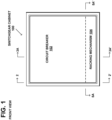
- FIG. 1 illustrates a front, overall view of the example switchgear cabinet 100, example circuit breaker 102, and example racking mechanism 104 that is an integral part of the circuit breaker 102.
- FIG. 2 is a side view along the section line 2-2' of FIG. 1 , illustrating the example breaker compartment 101 of the switchgear cabinet 100, the circuit breaker 102, line side primary contact 106, breaker power connector, primary electrical plug or stabs, to the main line bus 108 or connector of the switchgear cabinet, the load side primary contact 106' to the main load bus 108', and the racking mechanism 104 that is an integral part of the circuit breaker 102.
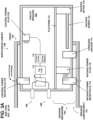
- FIG. 3A is a side view along the section line 3A-3A' of FIG. 1 , of the example circuit breaker102, showing the example racking mechanism 104 inside of the circuit breaker 102.
- the circuit breaker 102 is shown as having been initially positioned by a technician at the front entrance 103 to the breaker compartment 101.
- the circuit breaker 102 includes a main contacts switch 120 connected between the line side primary contact 106 and the load side primary contact 106'.
- the main contacts switch 120 is configured to interrupt current flowing from the line side primary contact 106 to the load side primary contact 106' in response to a trip signal from the trip logic 122 resulting from a fault signal from the current transformers CT, based on the settings stored in the settings memory 124.
- the example racking mechanism 104 includes a racking motor 110 that is configured to drive a mechanical linkage when receiving racking power, to move the circuit breaker 102 in the racking operation.
- An example mechanical linkage may be the racking screw 112 that is driven into rotation by the racking motor 110 to engage and advance through the threaded anchor 114 that is fastened to the bottom of the breaker compartment 101.
- the racking screw pulls the racking motor 110, and thus the circuit breaker 102, into the breaker compartment 101.
- the racking screw pushes the racking motor 110, and thus the circuit breaker 102, out of the breaker compartment 101.
- the example racking power plug 116 or first racking power connector is moveably mounted on a platform 115 that is fastened on the bottom side of the circuit breaker 102.
- the racking power plug is configured to conduct racking power and control signals to the racking motor 110.
- the example racking power receptacle 118 or second racking power connector is mounted at a stationary position on the interior bottom surface of the breaker compartment 101.
- the racking power receptacle 118 is configured to automatically connect with the racking power plug 116 when the circuit breaker 102 is advanced by the technician into the breaker compartment 101, to provide the racking power to the racking motor 110 through the connected racking power plug 116.
- the auxiliary power receptacle 118 and the threaded anchor 114 are positioned closer to the front 103 of the switchgear cabinet 100, to enable automatically connecting the racking power plug 116 to the racking power receptacle 118 as soon as the circuit breaker 102 is inserted into the breaker compartment 101 of the switchgear cabinet 100.
- the connector types of the first racking power connector 116 and the second racking power connector 118 may be reversed, so that the connector 116 is a receptacle-type connector and the connector 118 is a plug-type connector.
- Other types of mating electrical connectors may also be used in alternate embodiments for connectors 116 and 118, such as a finger cluster connector mated with a stab connector.
- the example control power plug 216 or first control power connector is shown mounted in the circuit breaker 102 in FIG. 3A .
- the control power plug 216 remains disconnected from the example control power receptacle 218 or second control power connector that is mounted in the breaker compartment 101 of the switchgear cabinet 100, while the circuit breaker moves within the breaker compartment during the racking operation.
- the control power plug 216 reaches the connected position of FIG. 3D , the control power plug 216 becomes connected to the control power receptacle 218.
- the circuit breaker is shown in the disconnected position in FIG. 3A , where the control power plug 216 is accessible to externally located equipment to conduct control power to control circuits 124 in the circuit breaker and to exchange control signals between the control circuits 124 and testing or other external equipment.
- the connector types of the first control power connector 216 and the second control power connector 218 may be reversed, so that the connector 216 is a receptacle-type connector and the connector 218 is a plug-type connector.
- Other types of mating electrical connectors may also be used in alternate embodiments for connectors 216 and 218, such as a finger cluster connector mated with a stab connector.
- the example circuit breaker 102 is initially positioned by the technician as shown in FIG. 3A , just prior to the racking power plug 116 connecting to the auxiliary power receptacle 118.
- the racking power plug 116 becomes connected to the auxiliary power receptacle 118 as shown in FIG. 3B , and racking power is made available to the racking motor 110.
- the adjusted position of the breaker by the technician also mates the racking screw 112 with the threaded anchor 114, which begins advancing the breaker 102 in the motorized racking operation.
- the racking motor 110 begins to advance through the threaded anchor 114, pulling the circuit breaker 102 further into the breaker compartment.
- FIG. 4A is a top view of the example platform 115 in the circuit breaker 102, showing the example relative positions of the racking power plug 116 and the racking power receptacle 118 corresponding to FIG. 3A .
- the circuit breaker 102 is shown as having been initially positioned at the entrance 103 to the breaker compartment 101.
- the slot 130 in the platform 115 guides the racking power plug 116 as it moves with respect to the platform 115 while the circuit breaker is racked into the breaker compartment.
- the figure shows the example retention spring 134 mounted on top of the platform 115 at the end of the slot 130 nearest the racking power receptacle 118, as shown in FIG. 3A .
- the retention spring 134 temporarily captures the stud 132 mounted on the top of the racking power plug 116, which projects upward through the slot 130, to enable the racking power plug 116 to travel along with the platform 115 as the circuit breaker is inserted into the breaker compartment.
- the contact pins of the racking power plug 116 are forced into the corresponding sockets of the racking power receptacle 118 as the racking power plug 116 continues to approach the racking power receptacle 118, as shown in FIGs. 3A and 3B .
- FIG. 5A is a top cross sectional view along the section line 5-5A of FIG. 1 , showing the first example embodiment of the racking mechanism 104 in the circuit breaker 102 when it is inserted into the switchgear cabinet 100.
- the initial positions of the racking power plug 116 and the racking power receptacle 118 correspond to that shown in FIGs. 3A and 4A .
- the auxiliary power receptacle 118 and the threaded anchor 114 are positioned closer to the front 103 of the switchgear cabinet 100, to enable connecting the racking power plug 116 to the racking power receptacle 118 as soon as the circuit breaker 102 is inserted into the breaker compartment 101 of the switchgear cabinet 100.
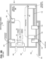
- FIG. 3B is a side interior view of the example circuit breaker of FIG. 3A , showing the racking power plug 116 connected with its contact pins inserted into the corresponding sockets of to the auxiliary power receptacle 118.
- the figure shows the position of the circuit breaker 102 when the technician has adjusted the position of the breaker to enable the racking power plug 116 to automatically connect to the racking power receptacle 118, where it can begin to apply racking power to the racking motor 110.
- the racking power plug 116 remains stationary with respect to the breaker compartment 101 as the circuit breaker 102 moves with respect to the breaker compartment 101, since the racking power plug 116 is now connected to the stationary racking power receptacle 118.
- the position of the breaker 102 also mates the racking screw 112 with the threaded anchor 114, which begins advancing the breaker 102 in the motorized racking operation.
- the control power plug 216 remains disconnected from the control power receptacle 218 mounted in the breaker compartment 101 of the switchgear cabinet 100, while the circuit breaker moves within the breaker compartment during the racking operation.
- FIG. 4B is a top view of the platform in the circuit breaker, showing the example relative positions of the racking power plug and the racking power receptacle corresponding to FIG. 3A , as electrical contact is made between the two plugs 116 and 118 and racking power is provided to the racking motor 110.
- the circuit breaker and platform 115 are moved by the racking motor 110 with respect to the racking power receptacle 118, the stud 132 on top of the racking power plug 116 is released from the retention spring 134, the racking power plug 116 being effectively pushed by the racking power receptacle 118 as the racking operation progresses.
- FIG. 3C is a side interior view of the example circuit breaker of FIG. 3B , showing the racking power plug 116 having remained plugged into the stationary racking power receptacle 118, so as to continue powering the racking motor 110 while the circuit breaker 102 is moved in the racking operation by the racking motor 110.
- the racking power plug 116 is moveably mounted on the platform 115 and is guided by the slot 130 in the platform 115 to move with respect to the platform 115 and the circuit breaker's structure, remaining in position in electrical contact with the racking power receptacle 118.
- the control power plug 216 remains disconnected from the control power receptacle 218 that is mounted in the breaker compartment 101 of the switchgear cabinet 100, while the circuit breaker moves within the breaker compartment during the racking operation.
- FIG. 4C is a top view of the platform in the circuit breaker, showing the example relative positions of the racking power plug and the racking power receptacle corresponding to FIG. 3C , as the circuit breaker moves during the racking operation.
- the racking power plug 116 is effectively pushed by the racking power receptacle 118 as the racking operation progresses.
- FIG. 3D is a side interior view of the example circuit breaker of FIG. 3C , showing the racking power plug 116 continuing to be plugged into the racking power receptacle 118 to continue powering the racking motor 110 as the circuit breaker 102 becomes fully racked with its line side primary contact 106 connected to the main line bus 108 and the load side primary contact 106' connected to the main load bus 108'.
- the example control power plug 216 is configured to connect to the control power receptacle 218 when the racking motor 110 has racked the circuit breaker 102 into the connected position of FIG. 3D and the racking operation is completed.
- the control power plug 216 and the connected control power receptacle 218 form the path to conduct control power to the control circuits 124 in the circuit breaker 102 and to exchange control signals between the control circuits 124 and testing or other equipment.
- the control power plug 216 is also configured to convey signals for settings and other control information to the settings memory 124 and the trip logic 122, when it is connected to the control power receptacle 218.
- FIG. 4D is a top view of the platform in the circuit breaker, showing the example relative positions of the racking power plug 116 and the racking power receptacle 118 corresponding to FIG. 3D as the circuit breaker becomes fully racked with its primary contacts 106 and 106' connecting with the main bus 108 and 108'.
- the connection of the primary contacts of the circuit breaker to the main bus is with a primary electrical plug or stabs in the circuit breaker.
- FIG. 5B is a top cross sectional view along the section line 5-5A of FIG. 1 , showing the second example embodiment of the racking mechanism 104 in the circuit breaker 102, with the racking power receptacle 118 and the threaded anchor 114 positioned closer to the front 103 of the switchgear cabinet 100, to enable connecting the racking power plug 116 to the racking power receptacle 118 as soon as the circuit breaker 102 is inserted into the breaker compartment 101 of the switchgear cabinet 100.
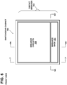
- FIG. 6 illustrates an alternate embodiment in a front, overall view of the example switchgear cabinet 100, example circuit breaker 102 comprising breaker circuits 105 and breaker base 107 that is an integral part of the circuit breaker 102.
- FIG. 7 is a side view along the section line 7-7' of the alternate embodiment of FIG. 6 , illustrating the example breaker compartment 101 of the switchgear cabinet 100, circuit breaker 102 comprising breaker circuits 105 and breaker base 107 that is an integral part of the circuit breaker 102, and primary contacts 106 and 106' to the main bus 108, 108'.
- FIG. 8A is a side view along the section line 8A-8A' of the alternate embodiment of FIG. 6 , of the example circuit breaker 102 comprising breaker circuits 105 and breaker base 107, inside of the circuit breaker 102.
- the racking motor 110 is fastened to the breaker base 107.
- the moveable carrier 109 is fastened to the bottom of the housing of the breaker circuits 105.
- the racking screw 112 is driven into rotation by the racking motor 110 to engage threads within the moveable carrier 109 and move the moveable carrier 109 and the breaker circuits 105 either toward or away from the contact position of the primary contacts 106 and 106' to the main bus 108, 108'.
- the racking power plug 116 is fastened to the breaker base 107.
- the racking power receptacle 118 is fastened to the switchgear cabinet 100.
- the initial position of the racking power plug 116 is shown in FIG. 8A before it connects to the racking power receptacle 118 when the circuit breaker 102 is initially inserted by a technician into the breaker compartment 101.
- the control power plug 216 is fastened to the top of the housing of the breaker circuits 105.
- the stationary control power receptacle 218 is fastened to the switchgear cabinet 100.
- the control power plug 216 remains disconnected from the stationary control power receptacle 218 while the breaker circuits 105 of the circuit breaker 102 moves within the breaker compartment 101 during the racking operation.
- the control power plug 216 Upon reaching the connected position of FIG. 8C , the control power plug 216 becomes connected to the stationary control power receptacle 218.
- FIG. 8B is a side interior view of the example circuit breaker 102 of the alternate embodiment of FIG. 8A , showing the position of the circuit breaker 102 when the technician has adjusted the position of the breaker base 107, enabling the racking power plug 116 to automatically connect to the stationary racking power receptacle 118, where it can begin to apply racking power to the racking motor 110.
- the breaker base 107 may be latched to the switchgear cabinet 100 at this point.
- the racking power plug 116 remains stationary with respect to the breaker compartment 101 as the breaker circuits 105 move with respect to the compartment 101, since the racking power plug 116 is now connected to the stationary racking power receptacle 118.
- the racking screw 112 mates with the moveable carrier 109, which begins advancing the breaker circuits 105 in the motorized racking operation.
- the control power plug 216 mounted in the moving breaker circuits 105, is shown remaining disconnected from the stationary control power receptacle 218.
- FIG. 8C is a side interior view of the example circuit breaker 102 of the alternate embodiment of FIG. 8B in the connected position, showing the racking power plug 116 continuing to be plugged into the racking power receptacle 118 to continue powering the racking motor 110 as the circuit breaker 102 becomes fully racked with its primary contacts 106 and 106' connecting with the main bus 108 and 108'.
- the control power plug 216 is shown connected to the stationary control power receptacle 218 upon reaching the connected position.
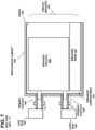
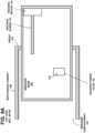
- FIG. 9A is a top cross sectional view along the section line 9-9A of the alternate embodiment of FIG. 6 , showing the first example embodiment of the breaker base 107 in the circuit breaker 102 when it is inserted into the switchgear cabinet 100, with the position of the racking motor 110 close to the front end of the breaker base 107 to thereby push the breaker circuits 105 toward the connected position of the circuit breaker 102, corresponding to FIG. 8A .
- FIG. 9B is a top cross sectional view along the section line 9-9A of the alternate embodiment of FIG. 6 , showing a second example embodiment of the breaker base 107 in the circuit breaker 102, with the racking motor 110 positioned close to the back end of the breaker base 107, to thereby pull the breaker circuits 105 toward the connected position of the circuit breaker 102, corresponding to FIG. 8A .
- the resulting apparatus and system provide a motorized breaker arrangement that powers-up the motor when the breaker is inserted into the cabinet and remains powered up when the breaker is in either a disconnected position or connected position, without having to manually connect plugs.
Landscapes
- Engineering & Computer Science (AREA)
- Power Engineering (AREA)
- Breakers (AREA)
Claims (8)
- Schutzschalter (102), umfassend:einen Verstellmotor (110), der in dem Schutzschalter (102) montiert ist und konfiguriert ist, um den Schutzschalter (102) in ein Schalterfach (101) zum Verbinden von Primärkontakten (106, 106') des Schutzschalters (102) in einer verbundenen Position mit einem Hauptbus (108) zu bewegen, wobei der Verstellmotor (110) konfiguriert ist, um ein Verstellgestänge (112) zum Verstellen des Schutzschalters (102) in das Schalterfach (101) anzutreiben, wenn er mit Verstellstrom versorgt wird;einen Steuerstromstecker (216), der in dem Schutzschalter (102) montiert ist und konfiguriert ist, um Steuerstrom durch Verbindung mit einer Steuerstromaufnahme (218) zu leiten, die an einer stationären Position in dem Schalterfach (101) montiert ist, wenn der Verstellmotor (110) den Schutzschalter (102) in die verbundene Position bewegt hat;einen Verstellstromstecker (116), der in dem Schutzschalter (102) montiert ist und konfiguriert ist, um den Verstellstrom zu dem Verstellmotor (110) durch Verbindung mit einer Verstellstromaufnahme (118) zu leiten, die an einer stationären Position in dem Schalterfach (101) montiert ist;wobei der Verstellstromstecker (116) ferner konfiguriert ist, um relativ zu der Verstellstromaufnahme (118) an seiner stationären Position in dem Schalterfach verbunden und stationär zu bleiben, während sich der Schutzschalter (102) während des Verstellvorgangs und nachdem der Schutzschalter (102) die verbundene Position erreicht hat, innerhalb des Schalterfachs (101) bewegt.
- Verstellsystem, umfassend den Schutzschalter (102) nach Anspruch 1 und ein Schalterfach (101), wobei:
eine Verstellstromaufnahme (118) an einer stationären Position in dem Schalterfach (101) montiert ist und konfiguriert ist, um sich automatisch mit dem Verstellstromstecker (116) zu verbinden, wenn der Schutzschalter (102) in das Schalterfach (101) eingeführt wird, um den Verstellstrom durch den verbundenen Verstellstromstecker (116) an den Verstellmotor (110) zu liefern. - Verstellsystem nach Anspruch 2, wobei sich der Schutzschalter (102) relativ zu dem Verstellstromstecker (116) bewegt, wenn der Verstellstromstecker (116) mit der stationären Verstellstromaufnahme (118) verbunden ist, während sich der Schutzschalter (102) während des Verstellvorgangs innerhalb des Schalterfachs (101) bewegt, und der Verstellstromstecker (116) nach dem Erreichen der verbundenen Position mit der Verstellstromaufnahme (118) verbunden bleibt.
- Verstellsystem nach einem der Ansprüche 2 oder 3, wobei sich der Steuerstromstecker (216), der in dem Schutzschalter (102) montiert ist, relativ zu der Steuerstromaufnahme (218), die in dem Schalterfach (101) montiert ist, bewegt und davon getrennt bleibt, während sich der Schutzschalter (102) während des Verstellvorgangs vor dem Erreichen der verbundenen Position, in der der Steuerstromstecker (216) mit der Steuerstromaufnahme (218) verbunden wird, innerhalb des Schalterfachs (101) bewegt.
- Verstellsystem nach einem der Ansprüche 2 bis 4, wobei der Verstellmotor (110) konfiguriert ist, um ein Verstellgestänge (112) zum Verstellen des Schutzschalters (102) in das Schalterfach (101) anzutreiben, wenn er über den Verstellstromstecker (116) und die Verstellstromaufnahme (118) mit Verstellstrom versorgt wird.
- Verstellsystem nach einem der Ansprüche 2 bis 5, wobei der Verstellstromstecker (116) konfiguriert ist, um sich mit der Verstellstromaufnahme (118) zu verbinden, wenn der Schutzschalter (102) in das Schalterfach (101) eintritt.
- Verstellsystem nach einem der Ansprüche 2 bis 6, wobei der Steuerstromstecker (216 von außerhalb des Schalterfachs (101) zugänglich ist, wenn der Schutzschalter (102) aus dem Schalterfach (101) herausgezogen wird.
- Verstellsystem nach einem der Ansprüche 2 bis 7, wobei die Verbindung der Primärkontakte (106, 106') des Schutzschalters mit dem Hauptbus (108) mit Primär-Stab-Verbinder in dem Schutzschalter (102) erfolgt, wenn der Verstellmotor (110) den Schutzschalter (102) in die verbundene Position bewegt hat.
Applications Claiming Priority (1)
| Application Number | Priority Date | Filing Date | Title |
|---|---|---|---|
| US202063131359P | 2020-12-29 | 2020-12-29 |
Publications (2)
| Publication Number | Publication Date |
|---|---|
| EP4024637A1 EP4024637A1 (de) | 2022-07-06 |
| EP4024637B1 true EP4024637B1 (de) | 2025-05-07 |
Family
ID=79024068
Family Applications (1)
| Application Number | Title | Priority Date | Filing Date |
|---|---|---|---|
| EP21214864.7A Active EP4024637B1 (de) | 2020-12-29 | 2021-12-15 | Leistungsschaltereinschub mit integriertem automatischen sekundärstecker |
Country Status (3)
| Country | Link |
|---|---|
| US (1) | US11984710B2 (de) |
| EP (1) | EP4024637B1 (de) |
| CN (1) | CN114695026A (de) |
Family Cites Families (7)
| Publication number | Priority date | Publication date | Assignee | Title |
|---|---|---|---|---|
| US5434369A (en) * | 1994-02-14 | 1995-07-18 | Abb Power T & D Company, Inc. | Automated secondary disconnect mechanism for electrical switchgear |
| JPH11285113A (ja) * | 1998-01-27 | 1999-10-15 | Fuji Electric Co Ltd | 引出し形遮断器 |
| PL385808A1 (pl) * | 2008-08-01 | 2010-02-15 | General Electric Company | Mechanizm wtórnego rozłączania do wysuwanego przerywacza obwodów oraz mechanizm wysuwania |
| US8304672B2 (en) | 2009-12-21 | 2012-11-06 | Schneider Electric USA, Inc. | Wireless remote racking mechanism |
| US8891229B2 (en) | 2011-09-26 | 2014-11-18 | Abb Technology Ag | Locking structure for a truck of a switchgear drawout circuit breaker |
| US9419473B2 (en) * | 2013-12-19 | 2016-08-16 | Eaton Corporation | Automatic transfer switch (ATS) bypass switch |
| US9490612B2 (en) | 2015-04-10 | 2016-11-08 | Abb Schweiz Ag | Switchgear manual control plug racking interlock structure |
-
2021
- 2021-12-15 EP EP21214864.7A patent/EP4024637B1/de active Active
- 2021-12-21 US US17/557,241 patent/US11984710B2/en active Active
- 2021-12-29 CN CN202111635880.6A patent/CN114695026A/zh active Pending
Also Published As
| Publication number | Publication date |
|---|---|
| EP4024637A1 (de) | 2022-07-06 |
| US20220209515A1 (en) | 2022-06-30 |
| CN114695026A (zh) | 2022-07-01 |
| US11984710B2 (en) | 2024-05-14 |
Similar Documents
| Publication | Publication Date | Title |
|---|---|---|
| CN201374888Y (zh) | 具有维持控制和通信连接的可抽出式单元的电气系统 | |
| EP2369702A1 (de) | Steckeingriffsvorrichtung für einen Schutzschalter und Schutzschalter damit | |
| CN105742125B (zh) | 断路器的二次回路连接组件和抽屉式断路器 | |
| CN101354988B (zh) | 可与断路器连接的剩余电流装置 | |
| EP2110836A2 (de) | Selbstlösende Kontakte für Zweitschaltungen und Schalter zum Herausziehen | |
| US10389093B2 (en) | Interlocking mechanism for circuit breaker | |
| KR101561620B1 (ko) | 전동기 제어반 | |
| CN101651067A (zh) | 用于抽出式断路器系统的辅助断开器 | |
| US20070184696A1 (en) | Device for parallel connection of a plurality of electrical feeder units | |
| US3341801A (en) | Multiple switch assembly | |
| US9742164B2 (en) | Secondary disconnect assembly for a switching device | |
| US11984710B2 (en) | Automatic secondary plug for integrated racking on breaker | |
| KR101759603B1 (ko) | 인출형 기중차단기의 제어단자 접속장치 | |
| US5594221A (en) | High ampere-circuit breaker secondary disconnect arrangement | |
| CN111404069B (zh) | 包括联锁模块的断路器的引入引出装置 | |
| DK165471B (da) | Elektrisk kobleudstyr | |
| KR20170101668A (ko) | 회로차단기의 위치검출스위치 장치 | |
| US20240388043A1 (en) | Plug connector with fuse device, and assembly comprising such a plug connector | |
| CN118352892A (zh) | 一种基于开关设备柜顶二次电缆接线盒 | |
| US20260121387A1 (en) | Interlock module, circuit breaker movement unit and switchboard comprising same | |
| CN104953419A (zh) | 断路器热插拔连接器 | |
| CN109412062B (zh) | 一种低压配电模块与系统 | |
| CN209282702U (zh) | 一种低压配电模块与系统 | |
| CN118589244B (zh) | 一种插接式高安全电源连接器 | |
| JP7740975B2 (ja) | 電源回路遮断ユニット、電源回路遮断装置及び電源回路on/off切替え方法 |
Legal Events
| Date | Code | Title | Description |
|---|---|---|---|
| PUAI | Public reference made under article 153(3) epc to a published international application that has entered the european phase |
Free format text: ORIGINAL CODE: 0009012 |
|
| STAA | Information on the status of an ep patent application or granted ep patent |
Free format text: STATUS: THE APPLICATION HAS BEEN PUBLISHED |
|
| AK | Designated contracting states |
Kind code of ref document: A1 Designated state(s): AL AT BE BG CH CY CZ DE DK EE ES FI FR GB GR HR HU IE IS IT LI LT LU LV MC MK MT NL NO PL PT RO RS SE SI SK SM TR |
|
| STAA | Information on the status of an ep patent application or granted ep patent |
Free format text: STATUS: REQUEST FOR EXAMINATION WAS MADE |
|
| 17P | Request for examination filed |
Effective date: 20221229 |
|
| RBV | Designated contracting states (corrected) |
Designated state(s): AL AT BE BG CH CY CZ DE DK EE ES FI FR GB GR HR HU IE IS IT LI LT LU LV MC MK MT NL NO PL PT RO RS SE SI SK SM TR |
|
| GRAP | Despatch of communication of intention to grant a patent |
Free format text: ORIGINAL CODE: EPIDOSNIGR1 |
|
| STAA | Information on the status of an ep patent application or granted ep patent |
Free format text: STATUS: GRANT OF PATENT IS INTENDED |
|
| INTG | Intention to grant announced |
Effective date: 20241212 |
|
| GRAS | Grant fee paid |
Free format text: ORIGINAL CODE: EPIDOSNIGR3 |
|
| GRAA | (expected) grant |
Free format text: ORIGINAL CODE: 0009210 |
|
| STAA | Information on the status of an ep patent application or granted ep patent |
Free format text: STATUS: THE PATENT HAS BEEN GRANTED |
|
| AK | Designated contracting states |
Kind code of ref document: B1 Designated state(s): AL AT BE BG CH CY CZ DE DK EE ES FI FR GB GR HR HU IE IS IT LI LT LU LV MC MK MT NL NO PL PT RO RS SE SI SK SM TR |
|
| REG | Reference to a national code |
Ref country code: GB Ref legal event code: FG4D |
|
| REG | Reference to a national code |
Ref country code: CH Ref legal event code: EP |
|
| REG | Reference to a national code |
Ref country code: DE Ref legal event code: R096 Ref document number: 602021030357 Country of ref document: DE |
|
| REG | Reference to a national code |
Ref country code: IE Ref legal event code: FG4D |
|
| REG | Reference to a national code |
Ref country code: NL Ref legal event code: MP Effective date: 20250507 |
|
| PG25 | Lapsed in a contracting state [announced via postgrant information from national office to epo] |
Ref country code: PT Free format text: LAPSE BECAUSE OF FAILURE TO SUBMIT A TRANSLATION OF THE DESCRIPTION OR TO PAY THE FEE WITHIN THE PRESCRIBED TIME-LIMIT Effective date: 20250908 Ref country code: ES Free format text: LAPSE BECAUSE OF FAILURE TO SUBMIT A TRANSLATION OF THE DESCRIPTION OR TO PAY THE FEE WITHIN THE PRESCRIBED TIME-LIMIT Effective date: 20250507 Ref country code: FI Free format text: LAPSE BECAUSE OF FAILURE TO SUBMIT A TRANSLATION OF THE DESCRIPTION OR TO PAY THE FEE WITHIN THE PRESCRIBED TIME-LIMIT Effective date: 20250507 |
|
| REG | Reference to a national code |
Ref country code: LT Ref legal event code: MG9D |
|
| PG25 | Lapsed in a contracting state [announced via postgrant information from national office to epo] |
Ref country code: NO Free format text: LAPSE BECAUSE OF FAILURE TO SUBMIT A TRANSLATION OF THE DESCRIPTION OR TO PAY THE FEE WITHIN THE PRESCRIBED TIME-LIMIT Effective date: 20250807 Ref country code: GR Free format text: LAPSE BECAUSE OF FAILURE TO SUBMIT A TRANSLATION OF THE DESCRIPTION OR TO PAY THE FEE WITHIN THE PRESCRIBED TIME-LIMIT Effective date: 20250808 |
|
| PG25 | Lapsed in a contracting state [announced via postgrant information from national office to epo] |
Ref country code: PL Free format text: LAPSE BECAUSE OF FAILURE TO SUBMIT A TRANSLATION OF THE DESCRIPTION OR TO PAY THE FEE WITHIN THE PRESCRIBED TIME-LIMIT Effective date: 20250507 Ref country code: NL Free format text: LAPSE BECAUSE OF FAILURE TO SUBMIT A TRANSLATION OF THE DESCRIPTION OR TO PAY THE FEE WITHIN THE PRESCRIBED TIME-LIMIT Effective date: 20250507 |
|
| REG | Reference to a national code |
Ref country code: AT Ref legal event code: MK05 Ref document number: 1793576 Country of ref document: AT Kind code of ref document: T Effective date: 20250507 |
|
| PG25 | Lapsed in a contracting state [announced via postgrant information from national office to epo] |
Ref country code: BG Free format text: LAPSE BECAUSE OF FAILURE TO SUBMIT A TRANSLATION OF THE DESCRIPTION OR TO PAY THE FEE WITHIN THE PRESCRIBED TIME-LIMIT Effective date: 20250507 |
|
| PG25 | Lapsed in a contracting state [announced via postgrant information from national office to epo] |
Ref country code: HR Free format text: LAPSE BECAUSE OF FAILURE TO SUBMIT A TRANSLATION OF THE DESCRIPTION OR TO PAY THE FEE WITHIN THE PRESCRIBED TIME-LIMIT Effective date: 20250507 |
|
| PG25 | Lapsed in a contracting state [announced via postgrant information from national office to epo] |
Ref country code: AT Free format text: LAPSE BECAUSE OF FAILURE TO SUBMIT A TRANSLATION OF THE DESCRIPTION OR TO PAY THE FEE WITHIN THE PRESCRIBED TIME-LIMIT Effective date: 20250507 |
|
| PG25 | Lapsed in a contracting state [announced via postgrant information from national office to epo] |
Ref country code: RS Free format text: LAPSE BECAUSE OF FAILURE TO SUBMIT A TRANSLATION OF THE DESCRIPTION OR TO PAY THE FEE WITHIN THE PRESCRIBED TIME-LIMIT Effective date: 20250807 |
|
| PG25 | Lapsed in a contracting state [announced via postgrant information from national office to epo] |
Ref country code: IS Free format text: LAPSE BECAUSE OF FAILURE TO SUBMIT A TRANSLATION OF THE DESCRIPTION OR TO PAY THE FEE WITHIN THE PRESCRIBED TIME-LIMIT Effective date: 20250907 |
|
| PG25 | Lapsed in a contracting state [announced via postgrant information from national office to epo] |
Ref country code: LV Free format text: LAPSE BECAUSE OF FAILURE TO SUBMIT A TRANSLATION OF THE DESCRIPTION OR TO PAY THE FEE WITHIN THE PRESCRIBED TIME-LIMIT Effective date: 20250507 |
|
| PGFP | Annual fee paid to national office [announced via postgrant information from national office to epo] |
Ref country code: GB Payment date: 20251223 Year of fee payment: 5 |
|
| PG25 | Lapsed in a contracting state [announced via postgrant information from national office to epo] |
Ref country code: DK Free format text: LAPSE BECAUSE OF FAILURE TO SUBMIT A TRANSLATION OF THE DESCRIPTION OR TO PAY THE FEE WITHIN THE PRESCRIBED TIME-LIMIT Effective date: 20250507 Ref country code: SM Free format text: LAPSE BECAUSE OF FAILURE TO SUBMIT A TRANSLATION OF THE DESCRIPTION OR TO PAY THE FEE WITHIN THE PRESCRIBED TIME-LIMIT Effective date: 20250507 |
|
| PGFP | Annual fee paid to national office [announced via postgrant information from national office to epo] |
Ref country code: FR Payment date: 20251223 Year of fee payment: 5 |
|
| PG25 | Lapsed in a contracting state [announced via postgrant information from national office to epo] |
Ref country code: CZ Free format text: LAPSE BECAUSE OF FAILURE TO SUBMIT A TRANSLATION OF THE DESCRIPTION OR TO PAY THE FEE WITHIN THE PRESCRIBED TIME-LIMIT Effective date: 20250507 |
|
| PG25 | Lapsed in a contracting state [announced via postgrant information from national office to epo] |
Ref country code: EE Free format text: LAPSE BECAUSE OF FAILURE TO SUBMIT A TRANSLATION OF THE DESCRIPTION OR TO PAY THE FEE WITHIN THE PRESCRIBED TIME-LIMIT Effective date: 20250507 |
|
| PG25 | Lapsed in a contracting state [announced via postgrant information from national office to epo] |
Ref country code: SK Free format text: LAPSE BECAUSE OF FAILURE TO SUBMIT A TRANSLATION OF THE DESCRIPTION OR TO PAY THE FEE WITHIN THE PRESCRIBED TIME-LIMIT Effective date: 20250507 Ref country code: RO Free format text: LAPSE BECAUSE OF FAILURE TO SUBMIT A TRANSLATION OF THE DESCRIPTION OR TO PAY THE FEE WITHIN THE PRESCRIBED TIME-LIMIT Effective date: 20250507 |
|
| PG25 | Lapsed in a contracting state [announced via postgrant information from national office to epo] |
Ref country code: IT Free format text: LAPSE BECAUSE OF FAILURE TO SUBMIT A TRANSLATION OF THE DESCRIPTION OR TO PAY THE FEE WITHIN THE PRESCRIBED TIME-LIMIT Effective date: 20250507 |
|
| REG | Reference to a national code |
Ref country code: DE Ref legal event code: R097 Ref document number: 602021030357 Country of ref document: DE |
|
| PLBE | No opposition filed within time limit |
Free format text: ORIGINAL CODE: 0009261 |
|
| STAA | Information on the status of an ep patent application or granted ep patent |
Free format text: STATUS: NO OPPOSITION FILED WITHIN TIME LIMIT |
|
| REG | Reference to a national code |
Ref country code: CH Ref legal event code: L10 Free format text: ST27 STATUS EVENT CODE: U-0-0-L10-L00 (AS PROVIDED BY THE NATIONAL OFFICE) Effective date: 20260318 |
|
| PGFP | Annual fee paid to national office [announced via postgrant information from national office to epo] |
Ref country code: DE Payment date: 20251229 Year of fee payment: 5 |
|
| 26N | No opposition filed |
Effective date: 20260210 |