EP4024572A1 - Battery pack having enhanced efficiency and stability of cooling fluid channel structure and vehicle comprising same - Google Patents
Battery pack having enhanced efficiency and stability of cooling fluid channel structure and vehicle comprising same Download PDFInfo
- Publication number
- EP4024572A1 EP4024572A1 EP21796342.0A EP21796342A EP4024572A1 EP 4024572 A1 EP4024572 A1 EP 4024572A1 EP 21796342 A EP21796342 A EP 21796342A EP 4024572 A1 EP4024572 A1 EP 4024572A1
- Authority
- EP
- European Patent Office
- Prior art keywords
- coolant
- floor panel
- battery pack
- battery
- pack according
- Prior art date
- Legal status (The legal status is an assumption and is not a legal conclusion. Google has not performed a legal analysis and makes no representation as to the accuracy of the status listed.)
- Granted
Links
Images




Classifications
-
- B—PERFORMING OPERATIONS; TRANSPORTING
- B60—VEHICLES IN GENERAL
- B60K—ARRANGEMENT OR MOUNTING OF PROPULSION UNITS OR OF TRANSMISSIONS IN VEHICLES; ARRANGEMENT OR MOUNTING OF PLURAL DIVERSE PRIME-MOVERS IN VEHICLES; AUXILIARY DRIVES FOR VEHICLES; INSTRUMENTATION OR DASHBOARDS FOR VEHICLES; ARRANGEMENTS IN CONNECTION WITH COOLING, AIR INTAKE, GAS EXHAUST OR FUEL SUPPLY OF PROPULSION UNITS IN VEHICLES
- B60K1/00—Arrangement or mounting of electrical propulsion units
- B60K1/04—Arrangement or mounting of electrical propulsion units of the electric storage means for propulsion
-
- B—PERFORMING OPERATIONS; TRANSPORTING
- B60—VEHICLES IN GENERAL
- B60L—PROPULSION OF ELECTRICALLY-PROPELLED VEHICLES; SUPPLYING ELECTRIC POWER FOR AUXILIARY EQUIPMENT OF ELECTRICALLY-PROPELLED VEHICLES; ELECTRODYNAMIC BRAKE SYSTEMS FOR VEHICLES IN GENERAL; MAGNETIC SUSPENSION OR LEVITATION FOR VEHICLES; MONITORING OPERATING VARIABLES OF ELECTRICALLY-PROPELLED VEHICLES; ELECTRIC SAFETY DEVICES FOR ELECTRICALLY-PROPELLED VEHICLES
- B60L50/00—Electric propulsion with power supplied within the vehicle
- B60L50/50—Electric propulsion with power supplied within the vehicle using propulsion power supplied by batteries or fuel cells
- B60L50/60—Electric propulsion with power supplied within the vehicle using propulsion power supplied by batteries or fuel cells using power supplied by batteries
- B60L50/64—Constructional details of batteries specially adapted for electric vehicles
-
- B—PERFORMING OPERATIONS; TRANSPORTING
- B60—VEHICLES IN GENERAL
- B60L—PROPULSION OF ELECTRICALLY-PROPELLED VEHICLES; SUPPLYING ELECTRIC POWER FOR AUXILIARY EQUIPMENT OF ELECTRICALLY-PROPELLED VEHICLES; ELECTRODYNAMIC BRAKE SYSTEMS FOR VEHICLES IN GENERAL; MAGNETIC SUSPENSION OR LEVITATION FOR VEHICLES; MONITORING OPERATING VARIABLES OF ELECTRICALLY-PROPELLED VEHICLES; ELECTRIC SAFETY DEVICES FOR ELECTRICALLY-PROPELLED VEHICLES
- B60L58/00—Methods or circuit arrangements for monitoring or controlling batteries or fuel cells, specially adapted for electric vehicles
- B60L58/10—Methods or circuit arrangements for monitoring or controlling batteries or fuel cells, specially adapted for electric vehicles for monitoring or controlling batteries
- B60L58/24—Methods or circuit arrangements for monitoring or controlling batteries or fuel cells, specially adapted for electric vehicles for monitoring or controlling batteries for controlling the temperature of batteries
- B60L58/26—Methods or circuit arrangements for monitoring or controlling batteries or fuel cells, specially adapted for electric vehicles for monitoring or controlling batteries for controlling the temperature of batteries by cooling
-
- B—PERFORMING OPERATIONS; TRANSPORTING
- B62—LAND VEHICLES FOR TRAVELLING OTHERWISE THAN ON RAILS
- B62D—MOTOR VEHICLES; TRAILERS
- B62D25/00—Superstructure or monocoque structure sub-units; Parts or details thereof not otherwise provided for
- B62D25/20—Floors or bottom sub-units
-
- B—PERFORMING OPERATIONS; TRANSPORTING
- B62—LAND VEHICLES FOR TRAVELLING OTHERWISE THAN ON RAILS
- B62D—MOTOR VEHICLES; TRAILERS
- B62D29/00—Superstructures, understructures, or sub-units thereof, characterised by the material thereof
- B62D29/008—Superstructures, understructures, or sub-units thereof, characterised by the material thereof predominantly of light alloys, e.g. extruded
-
- H—ELECTRICITY
- H01—ELECTRIC ELEMENTS
- H01M—PROCESSES OR MEANS, e.g. BATTERIES, FOR THE DIRECT CONVERSION OF CHEMICAL ENERGY INTO ELECTRICAL ENERGY
- H01M10/00—Secondary cells; Manufacture thereof
- H01M10/60—Heating or cooling; Temperature control
- H01M10/61—Types of temperature control
- H01M10/613—Cooling or keeping cold
-
- H—ELECTRICITY
- H01—ELECTRIC ELEMENTS
- H01M—PROCESSES OR MEANS, e.g. BATTERIES, FOR THE DIRECT CONVERSION OF CHEMICAL ENERGY INTO ELECTRICAL ENERGY
- H01M10/00—Secondary cells; Manufacture thereof
- H01M10/60—Heating or cooling; Temperature control
- H01M10/62—Heating or cooling; Temperature control specially adapted for specific applications
- H01M10/625—Vehicles
-
- H—ELECTRICITY
- H01—ELECTRIC ELEMENTS
- H01M—PROCESSES OR MEANS, e.g. BATTERIES, FOR THE DIRECT CONVERSION OF CHEMICAL ENERGY INTO ELECTRICAL ENERGY
- H01M10/00—Secondary cells; Manufacture thereof
- H01M10/60—Heating or cooling; Temperature control
- H01M10/65—Means for temperature control structurally associated with the cells
- H01M10/655—Solid structures for heat exchange or heat conduction
- H01M10/6551—Surfaces specially adapted for heat dissipation or radiation, e.g. fins or coatings
-
- H—ELECTRICITY
- H01—ELECTRIC ELEMENTS
- H01M—PROCESSES OR MEANS, e.g. BATTERIES, FOR THE DIRECT CONVERSION OF CHEMICAL ENERGY INTO ELECTRICAL ENERGY
- H01M10/00—Secondary cells; Manufacture thereof
- H01M10/60—Heating or cooling; Temperature control
- H01M10/65—Means for temperature control structurally associated with the cells
- H01M10/655—Solid structures for heat exchange or heat conduction
- H01M10/6556—Solid parts with flow channel passages or pipes for heat exchange
-
- H—ELECTRICITY
- H01—ELECTRIC ELEMENTS
- H01M—PROCESSES OR MEANS, e.g. BATTERIES, FOR THE DIRECT CONVERSION OF CHEMICAL ENERGY INTO ELECTRICAL ENERGY
- H01M10/00—Secondary cells; Manufacture thereof
- H01M10/60—Heating or cooling; Temperature control
- H01M10/65—Means for temperature control structurally associated with the cells
- H01M10/656—Means for temperature control structurally associated with the cells characterised by the type of heat-exchange fluid
- H01M10/6567—Liquids
- H01M10/6568—Liquids characterised by flow circuits, e.g. loops, located externally to the cells or cell casings
-
- H—ELECTRICITY
- H01—ELECTRIC ELEMENTS
- H01M—PROCESSES OR MEANS, e.g. BATTERIES, FOR THE DIRECT CONVERSION OF CHEMICAL ENERGY INTO ELECTRICAL ENERGY
- H01M50/00—Constructional details or processes of manufacture of the non-active parts of electrochemical cells other than fuel cells, e.g. hybrid cells
- H01M50/20—Mountings; Secondary casings or frames; Racks, modules or packs; Suspension devices; Shock absorbers; Transport or carrying devices; Holders
- H01M50/204—Racks, modules or packs for multiple batteries or multiple cells
-
- H—ELECTRICITY
- H01—ELECTRIC ELEMENTS
- H01M—PROCESSES OR MEANS, e.g. BATTERIES, FOR THE DIRECT CONVERSION OF CHEMICAL ENERGY INTO ELECTRICAL ENERGY
- H01M50/00—Constructional details or processes of manufacture of the non-active parts of electrochemical cells other than fuel cells, e.g. hybrid cells
- H01M50/20—Mountings; Secondary casings or frames; Racks, modules or packs; Suspension devices; Shock absorbers; Transport or carrying devices; Holders
- H01M50/249—Mountings; Secondary casings or frames; Racks, modules or packs; Suspension devices; Shock absorbers; Transport or carrying devices; Holders specially adapted for aircraft or vehicles, e.g. cars or trains
-
- H—ELECTRICITY
- H01—ELECTRIC ELEMENTS
- H01M—PROCESSES OR MEANS, e.g. BATTERIES, FOR THE DIRECT CONVERSION OF CHEMICAL ENERGY INTO ELECTRICAL ENERGY
- H01M50/00—Constructional details or processes of manufacture of the non-active parts of electrochemical cells other than fuel cells, e.g. hybrid cells
- H01M50/20—Mountings; Secondary casings or frames; Racks, modules or packs; Suspension devices; Shock absorbers; Transport or carrying devices; Holders
- H01M50/258—Modular batteries; Casings provided with means for assembling
-
- H—ELECTRICITY
- H01—ELECTRIC ELEMENTS
- H01M—PROCESSES OR MEANS, e.g. BATTERIES, FOR THE DIRECT CONVERSION OF CHEMICAL ENERGY INTO ELECTRICAL ENERGY
- H01M50/00—Constructional details or processes of manufacture of the non-active parts of electrochemical cells other than fuel cells, e.g. hybrid cells
- H01M50/20—Mountings; Secondary casings or frames; Racks, modules or packs; Suspension devices; Shock absorbers; Transport or carrying devices; Holders
- H01M50/262—Mountings; Secondary casings or frames; Racks, modules or packs; Suspension devices; Shock absorbers; Transport or carrying devices; Holders with fastening means, e.g. locks
- H01M50/264—Mountings; Secondary casings or frames; Racks, modules or packs; Suspension devices; Shock absorbers; Transport or carrying devices; Holders with fastening means, e.g. locks for cells or batteries, e.g. straps, tie rods or peripheral frames
-
- B—PERFORMING OPERATIONS; TRANSPORTING
- B60—VEHICLES IN GENERAL
- B60K—ARRANGEMENT OR MOUNTING OF PROPULSION UNITS OR OF TRANSMISSIONS IN VEHICLES; ARRANGEMENT OR MOUNTING OF PLURAL DIVERSE PRIME-MOVERS IN VEHICLES; AUXILIARY DRIVES FOR VEHICLES; INSTRUMENTATION OR DASHBOARDS FOR VEHICLES; ARRANGEMENTS IN CONNECTION WITH COOLING, AIR INTAKE, GAS EXHAUST OR FUEL SUPPLY OF PROPULSION UNITS IN VEHICLES
- B60K1/00—Arrangement or mounting of electrical propulsion units
- B60K2001/003—Arrangement or mounting of electrical propulsion units with means for cooling the electrical propulsion units
- B60K2001/005—Arrangement or mounting of electrical propulsion units with means for cooling the electrical propulsion units the electric storage means
-
- B—PERFORMING OPERATIONS; TRANSPORTING
- B60—VEHICLES IN GENERAL
- B60K—ARRANGEMENT OR MOUNTING OF PROPULSION UNITS OR OF TRANSMISSIONS IN VEHICLES; ARRANGEMENT OR MOUNTING OF PLURAL DIVERSE PRIME-MOVERS IN VEHICLES; AUXILIARY DRIVES FOR VEHICLES; INSTRUMENTATION OR DASHBOARDS FOR VEHICLES; ARRANGEMENTS IN CONNECTION WITH COOLING, AIR INTAKE, GAS EXHAUST OR FUEL SUPPLY OF PROPULSION UNITS IN VEHICLES
- B60K1/00—Arrangement or mounting of electrical propulsion units
- B60K1/04—Arrangement or mounting of electrical propulsion units of the electric storage means for propulsion
- B60K2001/0405—Arrangement or mounting of electrical propulsion units of the electric storage means for propulsion characterised by their position
- B60K2001/0438—Arrangement under the floor
-
- H—ELECTRICITY
- H01—ELECTRIC ELEMENTS
- H01M—PROCESSES OR MEANS, e.g. BATTERIES, FOR THE DIRECT CONVERSION OF CHEMICAL ENERGY INTO ELECTRICAL ENERGY
- H01M2220/00—Batteries for particular applications
- H01M2220/20—Batteries in motive systems, e.g. vehicle, ship, plane
-
- Y—GENERAL TAGGING OF NEW TECHNOLOGICAL DEVELOPMENTS; GENERAL TAGGING OF CROSS-SECTIONAL TECHNOLOGIES SPANNING OVER SEVERAL SECTIONS OF THE IPC; TECHNICAL SUBJECTS COVERED BY FORMER USPC CROSS-REFERENCE ART COLLECTIONS [XRACs] AND DIGESTS
- Y02—TECHNOLOGIES OR APPLICATIONS FOR MITIGATION OR ADAPTATION AGAINST CLIMATE CHANGE
- Y02E—REDUCTION OF GREENHOUSE GAS [GHG] EMISSIONS, RELATED TO ENERGY GENERATION, TRANSMISSION OR DISTRIBUTION
- Y02E60/00—Enabling technologies; Technologies with a potential or indirect contribution to GHG emissions mitigation
- Y02E60/10—Energy storage using batteries
Definitions
- the present disclosure relates to a battery pack, and more particularly, to a battery pack to which an assembly structure for efficient cooling path configuration and stable coolant supply and discharge is applied.
- Secondary batteries that are easy to apply according to product groups and have electrical characteristics such as high energy density are commonly applied to not only portable devices, but also electric vehicles (EVs) or hybrid electric vehicles (HEVs) driven by electric drive sources, and electric storage devices.
- EVs electric vehicles
- HEVs hybrid electric vehicles
- the secondary batteries are attracting attention as a new energy source for improving eco-friendliness and energy efficiency in that they do not generate any by-products from the use of energy as well as the primary advantage of dramatically reducing the use of fossil fuels.
- a battery pack applied to an electric vehicle or the like has a structure in which a plurality of cell assemblies having a plurality of unit cells are connected in series to obtain a high output.
- the unit cell may be repeatedly charged and discharged by an electric chemical reaction between components, including positive and negative electrode current collectors, a separator, an active material, an electrolyte, and the like.
- the battery pack with a multi-module structure applied to an electric vehicle is designed to have as high energy density per unit volume as possible because of the restriction on an installation space inside the vehicle and to easily dissipate the heat generated by the intensively arranged battery modules most of all.
- an indirect water cooling method as disclosed in Patent Document 1 Korean Unexamined Patent Publication No. 10-2015-0100365
- Patent Document 2 Korean Unexamined Patent Publication No. 10-2018-0081996
- a heatsink is coupled to an upper surface of a tray forming a bottom surface of a pack case, a thermal pad is interposed on the heatsink, and then a battery module is mounted on the thermal pad so that the heat of the battery module is dissipated to the outside through the thermal pad and the heatsink.
- the battery pack according to the prior art as disclosed in Patent Document 1 or Patent Document 2 may not be easily assembled since the number of components and fixing structures required to fix the heatsink to the upper surface of the tray increases and the layout of an inlet hose and an outlet hose for supplying a coolant to the heatsink is difficult.
- the present disclosure is designed to solve the problems of the related art, and therefore the present disclosure is directed to providing a battery pack capable of reducing the number of cooling components included in a pack housing and simplifying the assembly process by using an efficient the cooling path configuration.
- the present disclosure aims is directed to integrating a cooling path configuration having an easy layout and excellent durability into the pack housing stably.
- a battery pack comprising: battery modules provided with a heatsink; a pack housing including a floor panel having an upper surface on which the battery modules are placed and a lower surface in which coolant channels for supplying and discharging a coolant to/from the heatsink of the battery modules are provided, and a base plate disposed below the floor panel in a layered form; and a coolant supply pipe configured to selectively communicate with the coolant channels and be coupled to an upper surface of the floor panel and disposed along a right side line of the floor panel; and a coolant discharge pipe configured to selectively communicate with the coolant channels and be coupled to the upper surface of the floor panel and disposed along a left side line of the floor panel, wherein the coolant channels have a lower end fixedly coupled to the base plate.
- the coolant channels may be provided in a rectangular tube shape to extend from the right side line to the left side line, and the lower end of the coolant channel in a rectangular tube shape may be joined to the base plate by friction stir welding.
- the floor panel may further include a support member formed on the lower surface of the floor panel to protrude as much as a thickness of the coolant channel.
- the support member may have a longitudinal section of a ' ⁇ ' shape to extend from the right side line to the left side line.
- the heatsink may is configured as a bottom plate of the battery module.
- the coolant channels may include a first coolant channel configured to introduce a coolant into any one battery module and a second coolant channel configured to discharge a coolant from the any one battery module, and the first coolant channel and the second coolant channel may be provided in a plurality of pairs, and the plurality of pairs of first coolant channels and second coolant channels may be arranged at predetermined pattern intervals along a front and rear direction of the pack housing.
- the interval between the first coolant channel and the second coolant channel provided in a pair may be smaller than a width of the battery module.
- two injection ports may be provided for one first coolant channel and two discharge ports are provided for one second coolant channel.
- the battery modules may be arranged such that two battery modules face each other, respectively, and two battery modules facing each other may be configured such that a coolant is supplied thereto through one of the two injection ports, respectively, and a coolant is discharged therefrom through one of the two discharge ports, respectively.
- the pack housing may further include a front frame forming a front wall, a rear frame forming a rear wall, a right side frame forming a right wall and a left side frame forming a left wall, which are vertically coupled to the floor panel, respectively.
- the right side frame may include a first pipe protection membrane configured to cover the coolant supply pipe, and the left side frame may include a second pipe protection membrane configured to cover the coolant discharge pipe.
- the first pipe protection membrane may include a first horizontal plate disposed on the coolant supply pipe and a first vertical plate bent at one end of the first horizontal plate to extend downward so that an end line of the first vertical plate is welded to the floor panel
- the second pipe protection membrane may include a second horizontal plate disposed on the coolant discharge pipe and a second vertical plate formed at one end of the second horizontal plate to extend downward so that an end line of the second vertical plate is welded to the floor panel.
- At least one side of the battery modules may be fastened to the first horizontal plate or the second horizontal plate by a bolt.
- the floor panel, the front frame, the rear frame, the right side frame and the left side frame may be an aluminum extrusion structure, respectively.
- a vehicle comprising the battery pack described above.
- a battery pack capable of reducing the number of cooling components included in the pack housing and simplifying the assembly process by using an efficient cooling path configuration.
- the battery pack of the present disclosure includes battery modules integrated with a heatsink such as a cooling plate and a pack housing having coolant channels for supplying or discharging a coolant to/from the battery modules, the number of components of a cooling device or the number of components for fixing them to be installed inside the pack housing is reduced, thereby greatly simplifying the assembly process, compared to the prior art.
- the reliability of the cooling function may be maintained against shock or vibration.
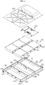
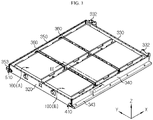
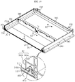
- FIG. 1 is a schematic perspective view showing a battery pack according to an embodiment of the present disclosure
- FIG. 2 is an exploded perspective view schematically showing the battery pack of FIG. 1
- FIG. 3 is a perspective view showing a pack housing in which battery modules of FIG. 2 are placed.
- a battery pack 10 includes a plurality of battery modules 100, an electric component assembly 200, a pack housing 300 and a pack cover 600.
- the battery module 100 may include a cell assembly (not shown) formed by stacking a plurality of battery cells (not shown), a module case 110 for accommodating the cell assembly, and a heatsink 130 (see FIG. 12 ).
- a pouch-type secondary battery may be employed as the battery cell, and the pouch-type secondary batteries may be configured to be erected vertically such that their wide surfaces are oriented upward and downward, and the pouch-type secondary batteries may be stacked in one direction to form a cell assembly.
- the module case 110 may be configured in a rectangular box shape to surround the outside of the cell assembly so that the cell assembly may be held therein. In order to sufficiently protect the cell assembly from swelling of the pouch-type secondary battery and external impact, it may be preferable that the module case 110 is made of a metal material with high mechanical rigidity.
- the heatsink 130 refers to an object that absorbs heat from another object by thermal contact and dissipates the heat, and may be provided in the form of a plate-shaped body having a channel therein.
- the heatsink 130 may be mounted under a bottom plate, which is a part of the module case 110, or may be provided to serve as a bottom plate of the module case 110 by itself to be integrated with the battery module 100.
- the heatsink 130 may have an entrance vertically connected to any one coolant channels 313A, 313B and an exit connected vertically to the other coolant channel 313A, 313B.
- a coolant may absorb heat from the battery cells while circulating along the channel formed inside the heatsink 130 through the entrance of the heatsink 130 in the any one coolant channels 313A, 313B, and discharge the heat out of the heatsink 130 through the exit of the heatsink 130 along the other coolant channels 313A, 313B.
- the battery pack 10 of this embodiment adopts a large-capacity battery module 100 whose size is 2 to 4 times larger than an existing general battery module 100, and compared with the conventional battery pack having the same capacity and output, the total number of battery modules 100 mounted in the pack housing 300 is small. In other words, by increasing the capacity of the battery module 100 so that a smaller number of large-capacity battery modules 100 are mounted in the pack housing 300, the number of parts such as inter-bus bars, harness cables and connectors may be reduced.
- the space occupancy purely occupied by battery cells may be further increased than the space occupancy occupied by the module cases 110 and its accessories inside the pack housing 300, compared to a conventional battery pack 10 in which general battery modules 100 are mounted, and thus there is an advantage in that the energy density per unit volume may be significantly improved.
- the high-capacity battery module 100 of this embodiment may include approximately 48 long cells per unit.
- the existing battery module 100 to which pouch-type secondary batteries are applied has a width (in a stacking direction of the pouch cells) of about 150 mm to 250 mm, but the large-capacity battery module 100 according to this embodiment has a width of about 800 mm.
- the electric component assembly 200 may include a relay device, a current sensor, a fuse, a BMS, a MSD (Manual Service Disconnector), and the like.
- the relay device is a switching component that selectively opens and closes a charging/discharging path through which a current flows, and may block the flow of a charging/discharging current when an abnormal situation occurs in the battery pack 10.
- the BMS refers to a battery management system that overall controls the charging/discharging operation of the battery modules 100, and may be regarded as a component commonly included in the battery pack 10.
- the MSD Manual Service Disconnector
- the electric component assembly 200 as above may be packaged so as not to be exposed to the outside by the pack housing 300 and the pack cover 600 together with the battery modules 100.
- the pack housing 300 provides a space to accommodate the battery modules 100 and the electric component assembly 200 therein, and may be regarded as a structure including a bracket 332 or mounting structures 343, 353 to be coupled to a vehicle body.
- the pack housing 300 provides a mechanical support to the battery modules 100 and the electric component assembly 200 and protects them from external shocks, so the pack housing 300 is preferably made of a metal material with high rigidity.
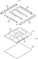
- the pack housing 300 may include a lower frame 310 provided in a wide plate shape on which the battery modules 100 may be placed, as well as a front frame 320, a rear frame 330, a right side frame 340 and a left side frame 350 vertically coupled along an edge of the lower frame 310 to form walls, and cross beams 360 coupled to both ends of the right side frame 340 and the left side frame 350.
- the lower frame 310, the front frame 320, the rear frame 330, the right side frame 340, the left side frame 350 and the cross beam 360 are an aluminum extrusion structure, respectively, and the pack housing 300 may be made by welding and bolting the frames.
- the frames are manufactured by extruding aluminum with empty spaces and ribs mixed therein, and the frames are welded to form the pack housing 300, thereby reducing the weight of the pack housing 300 and maintaining the mechanical rigidity at a reliable level or higher.
- coolant channels 313A, 313B are integrated in the lower frame 310 that constitutes the pack housing 300 of the present disclosure.
- the configuration of the lower frame 310 will be described in detail.
- the lower frame 310 may be provided in a double-layer structure including a floor panel 311 and a base plate 317.
- the base plate 317 is formed below the floor panel 311 in a layered form, and the floor panel 311 and the base plate 317 may be provided to have the same area.
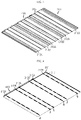
- the floor panel 311 includes an upper surface on which the battery modules 100 may be placed, coolant channels 313A, 313B for supplying or discharging a coolant to/from the heatsink 130 of the battery modules 100, and a lower surface on which a support member 315 is formed to maintain an interlayer interval with the base plate 317.
- the upper surface of the floor panel 311 is formed with a flat and wide surface so that the plurality of battery modules 100 may be arranged in a matrix on the same plane, and the lower surface of the floor panel 311 may be configured such that the coolant channels 313A, 313B and the support members 315 protrude in a tube or bar shape to form a convex pattern.
- the coolant channels 313A, 313B may be provided in a rectangular tube shape extending from a right side line to a left side line (in the Y-axis direction) of the floor panel.
- the coolant channels 313A, 313B may serve as passages for guiding the flow of coolant from the left side to the right side of the floor panel or from the right side to the left side of the floor panel.
- coolant channels 313A, 313B may be configured such that their lower ends are fixedly coupled to the base plate 317. Referring to FIGS. 8 to 9 , in this embodiment, the bottom surfaces of the coolant channels 313A, 313B in a rectangular tube shape and the base plate 317 are placed to be overlapped and then joined to each other by friction stir welding W.
- the coolant channels 313A, 313B and the base plate 317 are joined so that the coolant channels 313A, 313B are not hit when the base plate 317 vibrates.
- the floor panel 311 including the coolant channels 313A, 313B may be easily divided into 4 parts for easy aluminum extrusion, and the base plate 317 corresponding to a bottom end of the pack housing 300 may be made of a steel plate to maximize rigidity.
- the base plate 317 may be pressed, rotated and pressurized by pushing a tool such that the coolant channels 313A, 313B and the base plate 317 are joined. That is, by the pressure exceeding a certain limit, the base plate 317 and the lower surfaces of the coolant channels 313A, 313B are transformed like a liquid from a solid state so that the two metals are attached to each other.
- the friction stir welding does not require a separate welding material and is very eco-friendly because harmful rays and harmful gases are not generated.
- the support member 315 has a longitudinal section of a ' ⁇ ' shape to extend from the right side line to the left side line in parallel with the coolant channels 313A, 313B, and friction stir welding may also be applied to the base plate 317 like the coolant channels 313A, 313B. In this way, the floor panel 311 and the base plate 317 may be fixedly coupled firmly to form the lower frame 310.
- the battery pack 10 further includes a coolant supply pipe 400 for supplying a coolant to the coolant channels 313A, 313B, and a coolant discharge pipe 500 for discharging a coolant from the coolant channels 313A, 313B.
- the coolant supply pipe 400 may be coupled to the upper surface of the floor panel 311 and may be arranged along the right side line of the floor panel 311.
- an inlet port 410 of the coolant supply pipe 400 may be exposed out of the pack housing 300 through the front frame 320, and a coolant is injected into the inlet port 410 of the coolant supply pipe 400 from the outside to flow into the pack housing 300.
- the coolant supply pipe 400 may be covered by the right side frame 340 while the right side frame 340 is being coupled to the floor panel 311.
- the right side frame 340 may include a first pipe protection membrane 341 provided to cover the coolant supply pipe 400.
- the first pipe protection membrane 341 may include a first horizontal plate 341a disposed on the coolant supply pipe 400 and a first vertical plate 341b bent at one end of the first horizontal plate 341a to extend downward so that an end line thereof is coupled to the floor panel 311.
- the first pipe protection membrane 341 may be configured such that the first horizontal plate 341a and the first vertical plate 341b are elongated along the right side line of the floor panel 311 to cover the entire coolant supply pipe 400.
- the end line of the first vertical plate 341b is welded to the floor panel 311, so that, even when a coolant leaks from the coolant supply pipe 400, the coolant does not flow out to the upper surface of the floor panel 311, thereby preventing a short circuit accident.
- the first horizontal plate 341a may be used as a place for fixing the battery module 100.
- the battery module 100 may include a fastening block 120 configured to protrude from the module casing and provided so that a bolt B is inserted therein in a vertical direction.
- the fastening block 120 may be provided at a height capable of being placed on the upper surface of the first horizontal plate 341a inside the battery module 100.
- the battery modules 100 may be fixed to the right side frame 340 by fastening the bolt B to the fastening block 120 placed on the first horizontal plate 341a.
- the coolant discharge pipe 500 may be coupled to the upper surface of the floor panel 311 and may be provided to be disposed along the left side line of the floor panel 311.
- An outlet port 510 of the coolant discharge pipe 500 may be provided to be exposed out of the pack housing 300 through the front frame 320.
- the coolant inside the pack housing 300 may exit to the outside toward the front frame 320 through the outlet port 510 of the coolant discharge pipe 500.
- the coolant discharge pipe 500 may be covered by the left side frame 350 not to be exposed to the outside while the left side frame 350 is being coupled to the floor panel 311.
- the left side frame 350 may include a second pipe protection membrane 351 provided to cover the coolant discharge pipe 500.
- the second pipe protection membrane 351 may include a second horizontal plate 351a disposed on the coolant discharge pipe 500 and a second vertical plate 351b bent at one end of the second horizontal plate 351a to extend downward so that an end line thereof is welded to the floor panel 311.
- the second pipe protection membrane 351 may be provided symmetrically with the first pipe protection membrane 341 described above, and plays a role of protecting the coolant discharge pipe 500 from external impact and preventing a short circuit accident by blocking a coolant not to flow out the upper surface of the floor panel 311 even if the coolant leaks.
- the second horizontal plate 351a may be bolted to the fastening block 120 of the battery module 100, similar to the first horizontal plate 341a described above, to fix the battery module 100.
- the coolant channels 313A, 313B may be disposed to be spaced apart from each other in the following pattern along the front and rear direction (X-axis direction) of the pack housing 300.
- the coolant channels 313A, 313B may be classified into a first coolant channel 313A, which is the coolant channel 313A, 313B for introducing a coolant into any one battery module 100, and a second coolant channel 313B, which is the coolant channel 313A, 313B for discharging a coolant from the any one battery module 100.
- the first coolant channel 313A and the second coolant channel 313B may be provided in a plurality of pairs.
- the interval between the pair of the first coolant channel 313A and the second coolant channel 313B may be determined to be smaller than the width of the battery module 100.
- three pairs of coolant channels 313A, 313B are provided at the lower surface of floor panel 311 in the above-described pattern.
- the coolant supply pipe 400 and the coolant discharge pipe 500 are connected to selectively communicate with the coolant channels 313A, 313B.
- the coolant supply pipe 400 is connected to communicate with the first coolant channels 313A
- the coolant discharge pipe 500 is connected to communicate with the second coolant channels 313B.
- the coolant supply pipe 400 and the first coolant channel 313A may be connected by a pipe connector 420, respectively.
- a hole may be provided in a vertical direction at a right edge of the first coolant channel 313A, and a pipe connector 420 may be interposed between the hole and the coolant supply pipe 400.
- the coolant discharge pipe 500 may be connected to communicate only with the second coolant channels 313B in the same way as the coolant supply pipe 400.
- the coolant flowing in the coolant supply pipe 400 may move only to the first coolant channels 313A, and the coolant flowing in the second coolant channel 313B may move only to the coolant discharge pipe 500.
- two injection ports P1 may be provided for one first coolant channel 313A, and two discharge ports P2 may be provided for one second coolant channel 313B.
- the injection port P1 has a hole shape communicating vertically with the inner space of the first coolant channel 313A, and a sealing material may be provided around the hole.
- One of the two injection ports P1 may be positioned at a right side with respect to a (virtual) center line in the front and rear direction of the floor panel 311 and the other one may be positioned on a left side.
- the discharge port P2 may be provided in the same structure as the injection port P1 to communicate with the inner space of the second coolant channel 313B in a vertical direction. Therefore, the injection port P1 and the discharge port P2 are alternately provided along the front and rear direction (X-axis direction) of the floor panel 311.
- six injection ports P1 and six discharge ports P2 are provided at the upper surface of the floor panel 311, and two injection ports P1 and two discharge ports P2 are alternately provided in the front and rear direction (X- axis direction), repeatedly.
- six battery modules 100 according to this embodiment are provided in total, and they are arranged in two rows and three columns such that every two battery modules 100 face each other based on the center line of the floor panel 311.
- each battery module 100 includes a heatsink 130, the heatsink 130 may have an entrance and an exit (not shown) spaced apart from each other in the width direction of the battery module 100 so as to be vertically inserted into the injection port P1 and the discharge port P2 of the floor panel 311.
- Each of two battery modules 100A, 100B arranged to face each other may receive a coolant through one of two injection ports P1 communicating with the same first coolant channel 313A and discharge a coolant through one of two discharge ports P2 communicating with the same second coolant channel 313B.
- the coolant flowing through the coolant supply pipe 400 may be branched into three first coolant channels 313A and introduced into the heatsink 130 of the battery module 100 through the injection port P1.
- the coolant absorbing heat from the heatsink may be discharged to the second coolant channel 313B through the discharge port P2.
- the six battery modules 100 are placed on the floor panel 311 such that the entrance and exit (not shown) of each heatsink 130 are connected to the injection port P1 and the discharge port P2 of the floor panel 311. Accordingly, for all of the six battery modules, the battery cells accommodated therein may be cooled by a coolant flowing in the order of the coolant supply pipe 400 ⁇ the first coolant channel 313A ⁇ each battery module 100 ⁇ the second coolant channel 313B ⁇ the coolant discharge pipe 500.
- the coolant channels 313A, 313B, the injection port P1 and the discharge port P2 capable of supplying a coolant to the battery modules 100 or discharging a coolant from the battery modules 100 are integrated at the floor panel 311, and the heatsink 130 is integrated with the battery module 100.
- the battery pack 10 of the present disclosure configured as above has no other cooling parts that should be fixed or installed in the pack housing 300, except for the coolant supply pipe 400 and the coolant discharge pipe 500, so the assembly process of the battery pack 10 may be significantly simplified compared to the prior art.
- the coolant supply pipe 400 and the coolant discharge pipe 500 are covered and protected by the right side frame 340 and the left side frame 350, respectively, and the coolant channels 313A, 313B are joined to the base plate 317 by friction stir welding, so the cooling path may be maintained stably against shock or vibration.
- the battery pack 10 according to the present disclosure may be included as a power energy source of a vehicle such as an electric vehicle or a hybrid electric vehicle. That is, the vehicle according to the present disclosure may include the battery pack 10 described above.
Landscapes
- Engineering & Computer Science (AREA)
- Chemical & Material Sciences (AREA)
- Chemical Kinetics & Catalysis (AREA)
- General Chemical & Material Sciences (AREA)
- Electrochemistry (AREA)
- Manufacturing & Machinery (AREA)
- Mechanical Engineering (AREA)
- Transportation (AREA)
- Combustion & Propulsion (AREA)
- Sustainable Development (AREA)
- Life Sciences & Earth Sciences (AREA)
- Sustainable Energy (AREA)
- Power Engineering (AREA)
- Structural Engineering (AREA)
- Aviation & Aerospace Engineering (AREA)
- Architecture (AREA)
- Secondary Cells (AREA)
- Battery Mounting, Suspending (AREA)
- Cooling, Air Intake And Gas Exhaust, And Fuel Tank Arrangements In Propulsion Units (AREA)
- Arrangement Or Mounting Of Propulsion Units For Vehicles (AREA)
Abstract
Description
- The present disclosure relates to a battery pack, and more particularly, to a battery pack to which an assembly structure for efficient cooling path configuration and stable coolant supply and discharge is applied.
- The present application claims priority to
Korean Patent Application No. 10-2020-0052833 filed on April 29, 2020 - Secondary batteries that are easy to apply according to product groups and have electrical characteristics such as high energy density are commonly applied to not only portable devices, but also electric vehicles (EVs) or hybrid electric vehicles (HEVs) driven by electric drive sources, and electric storage devices. The secondary batteries are attracting attention as a new energy source for improving eco-friendliness and energy efficiency in that they do not generate any by-products from the use of energy as well as the primary advantage of dramatically reducing the use of fossil fuels.
- A battery pack applied to an electric vehicle or the like has a structure in which a plurality of cell assemblies having a plurality of unit cells are connected in series to obtain a high output. In addition, the unit cell may be repeatedly charged and discharged by an electric chemical reaction between components, including positive and negative electrode current collectors, a separator, an active material, an electrolyte, and the like.
- Meanwhile, as the need for a large-capacity structure, including its use as an energy storage source, increases recently, the demand for a battery pack having a multi-module structure in which a plurality of battery modules, each having a plurality of secondary batteries connected in series and/or parallel, are grouped is increasing.
- It is important that the battery pack with a multi-module structure applied to an electric vehicle is designed to have as high energy density per unit volume as possible because of the restriction on an installation space inside the vehicle and to easily dissipate the heat generated by the intensively arranged battery modules most of all. Among various methods of dissipating heat generated from the battery module, an indirect water cooling method as disclosed in Patent Document 1 (
Korean Unexamined Patent Publication No. 10-2015-0100365 Korean Unexamined Patent Publication No. 10-2018-0081996 - Seeing the cooling configuration of the indirect water-cooled battery pack according to the prior art, a heatsink is coupled to an upper surface of a tray forming a bottom surface of a pack case, a thermal pad is interposed on the heatsink, and then a battery module is mounted on the thermal pad so that the heat of the battery module is dissipated to the outside through the thermal pad and the heatsink.
- However, the battery pack according to the prior art as disclosed in Patent Document 1 or Patent Document 2 may not be easily assembled since the number of components and fixing structures required to fix the heatsink to the upper surface of the tray increases and the layout of an inlet hose and an outlet hose for supplying a coolant to the heatsink is difficult.
- In addition, even if the heatsink is fixed to the tray with a rivet or the like, the entire lower surface of the heatsink is not completely adhered to the upper surface of the tray, so a gap exists therebetween. For this reason, if an external shock is applied to the tray so that the tray vibrates, the heatsink may be damaged. As this situation continues, a crack may occur in the heatsink, resulting in coolant leakage.
- Accordingly, there is a demand for the development of a battery pack having a new cooling configuration that may supplement the problems of the water-cooled battery pack according to the prior art.
- The present disclosure is designed to solve the problems of the related art, and therefore the present disclosure is directed to providing a battery pack capable of reducing the number of cooling components included in a pack housing and simplifying the assembly process by using an efficient the cooling path configuration.
- In addition, the present disclosure aims is directed to integrating a cooling path configuration having an easy layout and excellent durability into the pack housing stably.
- These and other objects and advantages of the present disclosure may be understood from the following detailed description and will become more fully apparent from the exemplary embodiments of the present disclosure. Also, it will be easily understood that the objects and advantages of the present disclosure may be realized by the means shown in the appended claims and combinations thereof.
- In one aspect of the present disclosure, there is provided a battery pack, comprising: battery modules provided with a heatsink; a pack housing including a floor panel having an upper surface on which the battery modules are placed and a lower surface in which coolant channels for supplying and discharging a coolant to/from the heatsink of the battery modules are provided, and a base plate disposed below the floor panel in a layered form; and a coolant supply pipe configured to selectively communicate with the coolant channels and be coupled to an upper surface of the floor panel and disposed along a right side line of the floor panel; and a coolant discharge pipe configured to selectively communicate with the coolant channels and be coupled to the upper surface of the floor panel and disposed along a left side line of the floor panel, wherein the coolant channels have a lower end fixedly coupled to the base plate.
- The coolant channels may be provided in a rectangular tube shape to extend from the right side line to the left side line, and the lower end of the coolant channel in a rectangular tube shape may be joined to the base plate by friction stir welding.
- The floor panel may further include a support member formed on the lower surface of the floor panel to protrude as much as a thickness of the coolant channel.
- The support member may have a longitudinal section of a '⊥' shape to extend from the right side line to the left side line.
- The heatsink may is configured as a bottom plate of the battery module.
- The coolant channels may include a first coolant channel configured to introduce a coolant into any one battery module and a second coolant channel configured to discharge a coolant from the any one battery module, and the first coolant channel and the second coolant channel may be provided in a plurality of pairs, and the plurality of pairs of first coolant channels and second coolant channels may be arranged at predetermined pattern intervals along a front and rear direction of the pack housing.
- The interval between the first coolant channel and the second coolant channel provided in a pair may be smaller than a width of the battery module.
- In a central area of the floor panel, two injection ports may be provided for one first coolant channel and two discharge ports are provided for one second coolant channel.
- The battery modules may be arranged such that two battery modules face each other, respectively, and two battery modules facing each other may be configured such that a coolant is supplied thereto through one of the two injection ports, respectively, and a coolant is discharged therefrom through one of the two discharge ports, respectively.
- The pack housing may further include a front frame forming a front wall, a rear frame forming a rear wall, a right side frame forming a right wall and a left side frame forming a left wall, which are vertically coupled to the floor panel, respectively.
- The right side frame may include a first pipe protection membrane configured to cover the coolant supply pipe, and the left side frame may include a second pipe protection membrane configured to cover the coolant discharge pipe.
- The first pipe protection membrane may include a first horizontal plate disposed on the coolant supply pipe and a first vertical plate bent at one end of the first horizontal plate to extend downward so that an end line of the first vertical plate is welded to the floor panel, and the second pipe protection membrane may include a second horizontal plate disposed on the coolant discharge pipe and a second vertical plate formed at one end of the second horizontal plate to extend downward so that an end line of the second vertical plate is welded to the floor panel.
- At least one side of the battery modules may be fastened to the first horizontal plate or the second horizontal plate by a bolt.
- The floor panel, the front frame, the rear frame, the right side frame and the left side frame may be an aluminum extrusion structure, respectively.
- Meanwhile, in another aspect of the present disclosure, there may be provided a vehicle, comprising the battery pack described above.
- According to an embodiment of the present disclosure, it is possible to provide a battery pack capable of reducing the number of cooling components included in the pack housing and simplifying the assembly process by using an efficient cooling path configuration.
- More specifically, since the battery pack of the present disclosure includes battery modules integrated with a heatsink such as a cooling plate and a pack housing having coolant channels for supplying or discharging a coolant to/from the battery modules, the number of components of a cooling device or the number of components for fixing them to be installed inside the pack housing is reduced, thereby greatly simplifying the assembly process, compared to the prior art.
- In addition, in the battery pack of the present disclosure, since the coolant channels are connected to the base plate and the cooling path structure is designed stably, the reliability of the cooling function may be maintained against shock or vibration.
- Other effects of the present disclosure may be understood by the following description and will be more clearly understood by the embodiments of the present disclosure.
-
-
FIG. 1 is a schematic perspective view showing a battery pack according to an embodiment of the present disclosure. -
FIG. 2 is an exploded perspective view schematically showing the battery pack ofFIG. 1 . -
FIG. 3 is a perspective view showing a pack housing in which battery modules ofFIG. 2 are placed. -
FIG. 4 is an exploded perspective view showing the pack housing ofFIG. 3 . -
FIG. 5 is an assembled perspective view showing the pack housing ofFIG. 4 . -
FIG. 6 is a diagram showing an upper surface of a floor panel ofFIG. 4 . -
FIG. 7 is a diagram showing a lower surface of the floor panel ofFIG. 6 . -
FIG. 8 is a diagram showing a state where a base plate is welded to the floor panel ofFIG. 7 . -
FIG. 9 is a partial sectional view showing the pack housing according to an embodiment of the present disclosure. -
FIG. 10 is a sectioned perspective view showing the pack housing, taken along the line I-I' ofFIG. 5 . -
FIG. 11 is a sectioned perspective view showing the pack housing, taken along the line II-II' ofFIG. 5 . -
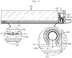
FIG. 12 is a sectioned view, taken along the line III-III' ofFIG. 3 . - Hereinafter, preferred embodiments of the present disclosure will be described in detail with reference to the accompanying drawings. Prior to the description, it should be understood that the terms used in the specification and the appended claims should not be construed as limited to general and dictionary meanings, but interpreted based on the meanings and concepts corresponding to technical aspects of the present disclosure on the basis of the principle that the inventor is allowed to define terms appropriately for the best explanation. Therefore, the description proposed herein is just a preferable example for the purpose of illustrations only, not intended to limit the scope of the disclosure, so it should be understood that other equivalents and modifications could be made thereto without departing from the scope of the disclosure.
-
FIG. 1 is a schematic perspective view showing a battery pack according to an embodiment of the present disclosure,FIG. 2 is an exploded perspective view schematically showing the battery pack ofFIG. 1 , andFIG. 3 is a perspective view showing a pack housing in which battery modules ofFIG. 2 are placed. - Referring to these drawings, a
battery pack 10 according to an embodiment of the present disclosure includes a plurality ofbattery modules 100, anelectric component assembly 200, apack housing 300 and apack cover 600. - The
battery module 100 may include a cell assembly (not shown) formed by stacking a plurality of battery cells (not shown), amodule case 110 for accommodating the cell assembly, and a heatsink 130 (seeFIG. 12 ). - For example, a pouch-type secondary battery may be employed as the battery cell, and the pouch-type secondary batteries may be configured to be erected vertically such that their wide surfaces are oriented upward and downward, and the pouch-type secondary batteries may be stacked in one direction to form a cell assembly.
- The
module case 110 may be configured in a rectangular box shape to surround the outside of the cell assembly so that the cell assembly may be held therein. In order to sufficiently protect the cell assembly from swelling of the pouch-type secondary battery and external impact, it may be preferable that themodule case 110 is made of a metal material with high mechanical rigidity. - The heatsink 130 (see
FIG. 12 ) refers to an object that absorbs heat from another object by thermal contact and dissipates the heat, and may be provided in the form of a plate-shaped body having a channel therein. Theheatsink 130 may be mounted under a bottom plate, which is a part of themodule case 110, or may be provided to serve as a bottom plate of themodule case 110 by itself to be integrated with thebattery module 100. - When the
battery module 100 is placed on an upper surface of afloor panel 311, explained later, theheatsink 130 may have an entrance vertically connected to any onecoolant channels other coolant channel - As will be described in detail later, a coolant may absorb heat from the battery cells while circulating along the channel formed inside the
heatsink 130 through the entrance of theheatsink 130 in the any onecoolant channels heatsink 130 through the exit of theheatsink 130 along theother coolant channels - Meanwhile, in order to increase the capacity and output of the
battery pack 10, a large number ofbattery modules 100 are required, and accordingly, the number of parts such as inter-bus bars for wiring between thebattery modules 100, harness cables for transmitting voltage data and temperature data of eachbattery module 100 to a BMS (Battery Management System), connectors, or the like increases. - The
battery pack 10 of this embodiment adopts a large-capacity battery module 100 whose size is 2 to 4 times larger than an existinggeneral battery module 100, and compared with the conventional battery pack having the same capacity and output, the total number ofbattery modules 100 mounted in thepack housing 300 is small. In other words, by increasing the capacity of thebattery module 100 so that a smaller number of large-capacity battery modules 100 are mounted in thepack housing 300, the number of parts such as inter-bus bars, harness cables and connectors may be reduced. - In addition, in the
battery pack 10 of the present disclosure in which large-capacity battery modules 100 are mounted, the space occupancy purely occupied by battery cells may be further increased than the space occupancy occupied by themodule cases 110 and its accessories inside thepack housing 300, compared to aconventional battery pack 10 in whichgeneral battery modules 100 are mounted, and thus there is an advantage in that the energy density per unit volume may be significantly improved. - For reference, the high-
capacity battery module 100 of this embodiment may include approximately 48 long cells per unit. For reference, the existingbattery module 100 to which pouch-type secondary batteries are applied has a width (in a stacking direction of the pouch cells) of about 150 mm to 250 mm, but the large-capacity battery module 100 according to this embodiment has a width of about 800 mm. - The
electric component assembly 200 may include a relay device, a current sensor, a fuse, a BMS, a MSD (Manual Service Disconnector), and the like. The relay device is a switching component that selectively opens and closes a charging/discharging path through which a current flows, and may block the flow of a charging/discharging current when an abnormal situation occurs in thebattery pack 10. The BMS refers to a battery management system that overall controls the charging/discharging operation of thebattery modules 100, and may be regarded as a component commonly included in thebattery pack 10. In addition, the MSD (Manual Service Disconnector) is a system to selectively cut off the power of a high-voltage battery by a physical method, and when necessary, the MSD disconnects a service plug to cut off the power. - The
electric component assembly 200 as above may be packaged so as not to be exposed to the outside by thepack housing 300 and thepack cover 600 together with thebattery modules 100. - The
pack housing 300 provides a space to accommodate thebattery modules 100 and theelectric component assembly 200 therein, and may be regarded as a structure including abracket 332 or mountingstructures - The
pack housing 300 provides a mechanical support to thebattery modules 100 and theelectric component assembly 200 and protects them from external shocks, so thepack housing 300 is preferably made of a metal material with high rigidity. - Specifically, as shown in
FIGS. 4 and5 , thepack housing 300 according to this embodiment may include alower frame 310 provided in a wide plate shape on which thebattery modules 100 may be placed, as well as afront frame 320, arear frame 330, aright side frame 340 and aleft side frame 350 vertically coupled along an edge of thelower frame 310 to form walls, and crossbeams 360 coupled to both ends of theright side frame 340 and theleft side frame 350. - The
lower frame 310, thefront frame 320, therear frame 330, theright side frame 340, theleft side frame 350 and thecross beam 360 are an aluminum extrusion structure, respectively, and thepack housing 300 may be made by welding and bolting the frames. - For example, the frames are manufactured by extruding aluminum with empty spaces and ribs mixed therein, and the frames are welded to form the
pack housing 300, thereby reducing the weight of thepack housing 300 and maintaining the mechanical rigidity at a reliable level or higher. - Meanwhile, the
coolant channels lower frame 310 that constitutes thepack housing 300 of the present disclosure. Hereinafter, the configuration of thelower frame 310 will be described in detail. - The
lower frame 310 according to the present disclosure may be provided in a double-layer structure including afloor panel 311 and abase plate 317. For example, thebase plate 317 is formed below thefloor panel 311 in a layered form, and thefloor panel 311 and thebase plate 317 may be provided to have the same area. - As shown in
FIGS. 6 and7 , thefloor panel 311 includes an upper surface on which thebattery modules 100 may be placed,coolant channels heatsink 130 of thebattery modules 100, and a lower surface on which asupport member 315 is formed to maintain an interlayer interval with thebase plate 317. - The upper surface of the
floor panel 311 is formed with a flat and wide surface so that the plurality ofbattery modules 100 may be arranged in a matrix on the same plane, and the lower surface of thefloor panel 311 may be configured such that thecoolant channels support members 315 protrude in a tube or bar shape to form a convex pattern. - The
coolant channels coolant channels - In addition, the
coolant channels base plate 317. Referring toFIGS. 8 to 9 , in this embodiment, the bottom surfaces of thecoolant channels base plate 317 are placed to be overlapped and then joined to each other by friction stir welding W. - For example, even if there is a slight gap between the
coolant channels base plate 317, there is a risk that thecoolant channels base plate 317 vibrates. Accordingly, in the present disclosure, in order to prevent this situation, thecoolant channels base plate 317 are joined so that thecoolant channels base plate 317 vibrates. - For reference, the
floor panel 311 including thecoolant channels base plate 317 corresponding to a bottom end of thepack housing 300 may be made of a steel plate to maximize rigidity. - In general, different kinds of metals such as aluminum and steel are difficult to attach to each other and are often joined using a rivet. However, the joined surface without a rivet may float, resulting in incomplete contact. In order to solve the problem of the rivet method, in this embodiment, friction stir welding is used such that the
coolant channels base plate 317 along an extension direction thereof. - In other words, after the lower surfaces of the
coolant channels base plate 317, thebase plate 317 may be pressed, rotated and pressurized by pushing a tool such that thecoolant channels base plate 317 are joined. That is, by the pressure exceeding a certain limit, thebase plate 317 and the lower surfaces of thecoolant channels - The friction stir welding does not require a separate welding material and is very eco-friendly because harmful rays and harmful gases are not generated.
- The
support member 315 has a longitudinal section of a '⊥' shape to extend from the right side line to the left side line in parallel with thecoolant channels base plate 317 like thecoolant channels floor panel 311 and thebase plate 317 may be fixedly coupled firmly to form thelower frame 310. - Referring to
FIGS. 10 to 12 along withFIGS. 6 and7 , thebattery pack 10 according to the present disclosure further includes acoolant supply pipe 400 for supplying a coolant to thecoolant channels coolant discharge pipe 500 for discharging a coolant from thecoolant channels - The
coolant supply pipe 400 may be coupled to the upper surface of thefloor panel 311 and may be arranged along the right side line of thefloor panel 311. In addition, aninlet port 410 of thecoolant supply pipe 400 may be exposed out of thepack housing 300 through thefront frame 320, and a coolant is injected into theinlet port 410 of thecoolant supply pipe 400 from the outside to flow into thepack housing 300. - The
coolant supply pipe 400 may be covered by theright side frame 340 while theright side frame 340 is being coupled to thefloor panel 311. To this end, theright side frame 340 may include a firstpipe protection membrane 341 provided to cover thecoolant supply pipe 400. Referring toFIG. 10 , the firstpipe protection membrane 341 may include a firsthorizontal plate 341a disposed on thecoolant supply pipe 400 and a firstvertical plate 341b bent at one end of the firsthorizontal plate 341a to extend downward so that an end line thereof is coupled to thefloor panel 311. - The first
pipe protection membrane 341 may be configured such that the firsthorizontal plate 341a and the firstvertical plate 341b are elongated along the right side line of thefloor panel 311 to cover the entirecoolant supply pipe 400. In addition, the end line of the firstvertical plate 341b is welded to thefloor panel 311, so that, even when a coolant leaks from thecoolant supply pipe 400, the coolant does not flow out to the upper surface of thefloor panel 311, thereby preventing a short circuit accident. - Also, the first
horizontal plate 341a may be used as a place for fixing thebattery module 100. For example, as shown inFIG. 12 , thebattery module 100 may include afastening block 120 configured to protrude from the module casing and provided so that a bolt B is inserted therein in a vertical direction. Thefastening block 120 may be provided at a height capable of being placed on the upper surface of the firsthorizontal plate 341a inside thebattery module 100. Thebattery modules 100 may be fixed to theright side frame 340 by fastening the bolt B to thefastening block 120 placed on the firsthorizontal plate 341a. - The
coolant discharge pipe 500 may be coupled to the upper surface of thefloor panel 311 and may be provided to be disposed along the left side line of thefloor panel 311. - An
outlet port 510 of thecoolant discharge pipe 500 may be provided to be exposed out of thepack housing 300 through thefront frame 320. The coolant inside thepack housing 300 may exit to the outside toward thefront frame 320 through theoutlet port 510 of thecoolant discharge pipe 500. - Similar to the
coolant supply pipe 400 described above, thecoolant discharge pipe 500 may be covered by theleft side frame 350 not to be exposed to the outside while theleft side frame 350 is being coupled to thefloor panel 311. - To this end, the
left side frame 350 may include a secondpipe protection membrane 351 provided to cover thecoolant discharge pipe 500. The secondpipe protection membrane 351 may include a secondhorizontal plate 351a disposed on thecoolant discharge pipe 500 and a secondvertical plate 351b bent at one end of the secondhorizontal plate 351a to extend downward so that an end line thereof is welded to thefloor panel 311. - That is, the second
pipe protection membrane 351 may be provided symmetrically with the firstpipe protection membrane 341 described above, and plays a role of protecting thecoolant discharge pipe 500 from external impact and preventing a short circuit accident by blocking a coolant not to flow out the upper surface of thefloor panel 311 even if the coolant leaks. - In addition, the second
horizontal plate 351a may be bolted to thefastening block 120 of thebattery module 100, similar to the firsthorizontal plate 341a described above, to fix thebattery module 100. - Hereinafter, the cooling path structure of the
battery pack 10 according to the present disclosure will be described in more detail with reference toFIGS. 6 and7 andFIGS. 10 to 12 again. - The
coolant channels pack housing 300. - Referring to
FIGS. 6 and7 , thecoolant channels first coolant channel 313A, which is thecoolant channel battery module 100, and asecond coolant channel 313B, which is thecoolant channel battery module 100. Thefirst coolant channel 313A and thesecond coolant channel 313B may be provided in a plurality of pairs. The interval between the pair of thefirst coolant channel 313A and thesecond coolant channel 313B may be determined to be smaller than the width of thebattery module 100. In this embodiment, three pairs ofcoolant channels floor panel 311 in the above-described pattern. - The
coolant supply pipe 400 and thecoolant discharge pipe 500 are connected to selectively communicate with thecoolant channels - More specifically, the
coolant supply pipe 400 is connected to communicate with thefirst coolant channels 313A, and thecoolant discharge pipe 500 is connected to communicate with thesecond coolant channels 313B. - At this time, the
coolant supply pipe 400 and thefirst coolant channel 313A may be connected by apipe connector 420, respectively. For example, as shown inFIG. 10 , a hole may be provided in a vertical direction at a right edge of thefirst coolant channel 313A, and apipe connector 420 may be interposed between the hole and thecoolant supply pipe 400. Thecoolant discharge pipe 500 may be connected to communicate only with thesecond coolant channels 313B in the same way as thecoolant supply pipe 400. - According to this configuration, the coolant flowing in the
coolant supply pipe 400 may move only to thefirst coolant channels 313A, and the coolant flowing in thesecond coolant channel 313B may move only to thecoolant discharge pipe 500. - Referring to
FIGS. 6 and11 , in a central area of thefloor panel 311, two injection ports P1 may be provided for onefirst coolant channel 313A, and two discharge ports P2 may be provided for onesecond coolant channel 313B. - The injection port P1 has a hole shape communicating vertically with the inner space of the
first coolant channel 313A, and a sealing material may be provided around the hole. One of the two injection ports P1 may be positioned at a right side with respect to a (virtual) center line in the front and rear direction of thefloor panel 311 and the other one may be positioned on a left side. - The discharge port P2 may be provided in the same structure as the injection port P1 to communicate with the inner space of the
second coolant channel 313B in a vertical direction. Therefore, the injection port P1 and the discharge port P2 are alternately provided along the front and rear direction (X-axis direction) of thefloor panel 311. - That is, in this embodiment, six injection ports P1 and six discharge ports P2 are provided at the upper surface of the
floor panel 311, and two injection ports P1 and two discharge ports P2 are alternately provided in the front and rear direction (X- axis direction), repeatedly. - In addition, six
battery modules 100 according to this embodiment (seeFIG. 3 ) are provided in total, and they are arranged in two rows and three columns such that every twobattery modules 100 face each other based on the center line of thefloor panel 311. - The bottom surface of each
battery module 100 includes aheatsink 130, theheatsink 130 may have an entrance and an exit (not shown) spaced apart from each other in the width direction of thebattery module 100 so as to be vertically inserted into the injection port P1 and the discharge port P2 of thefloor panel 311. - Each of two battery modules 100A, 100B arranged to face each other may receive a coolant through one of two injection ports P1 communicating with the same
first coolant channel 313A and discharge a coolant through one of two discharge ports P2 communicating with the samesecond coolant channel 313B. - In other words, as shown in
FIG. 12 , the coolant flowing through thecoolant supply pipe 400 may be branched into threefirst coolant channels 313A and introduced into theheatsink 130 of thebattery module 100 through the injection port P1. In addition, the coolant absorbing heat from the heatsink may be discharged to thesecond coolant channel 313B through the discharge port P2. - That is, the six
battery modules 100 are placed on thefloor panel 311 such that the entrance and exit (not shown) of eachheatsink 130 are connected to the injection port P1 and the discharge port P2 of thefloor panel 311. Accordingly, for all of the six battery modules, the battery cells accommodated therein may be cooled by a coolant flowing in the order of thecoolant supply pipe 400 → thefirst coolant channel 313A → eachbattery module 100 → thesecond coolant channel 313B → thecoolant discharge pipe 500. - As described above, in the
battery pack 10 of the present disclosure, thecoolant channels battery modules 100 or discharging a coolant from thebattery modules 100 are integrated at thefloor panel 311, and theheatsink 130 is integrated with thebattery module 100. Thebattery pack 10 of the present disclosure configured as above has no other cooling parts that should be fixed or installed in thepack housing 300, except for thecoolant supply pipe 400 and thecoolant discharge pipe 500, so the assembly process of thebattery pack 10 may be significantly simplified compared to the prior art. - In addition, the
coolant supply pipe 400 and thecoolant discharge pipe 500 are covered and protected by theright side frame 340 and theleft side frame 350, respectively, and thecoolant channels base plate 317 by friction stir welding, so the cooling path may be maintained stably against shock or vibration. - Meanwhile, the
battery pack 10 according to the present disclosure may be included as a power energy source of a vehicle such as an electric vehicle or a hybrid electric vehicle. That is, the vehicle according to the present disclosure may include thebattery pack 10 described above. - The present disclosure has been described in detail. However, it should be understood that the detailed description and specific examples, while indicating preferred embodiments of the disclosure, are given by way of illustration only, since various changes and modifications within the scope of the disclosure will become apparent to those skilled in the art from this detailed description.
- Meanwhile, when the terms indicating up, down, left and right directions are used in the specification, it is obvious to those skilled in the art that these merely represent relative locations for convenience in explanation and may vary based on a location of an observer or an object to be observed.
Claims (15)
- A battery pack, comprising:battery modules provided with a heatsink;a pack housing including a floor panel having an upper surface on which the battery modules are placed and a lower surface in which coolant channels for supplying and discharging a coolant to/from the heatsink of the battery modules are provided, and a base plate disposed below the floor panel in a layered form; anda coolant supply pipe configured to selectively communicate with the coolant channels and be coupled to an upper surface of the floor panel and disposed along a right side line of the floor panel; anda coolant discharge pipe configured to selectively communicate with the coolant channels and be coupled to the upper surface of the floor panel and disposed along a left side line of the floor panel,wherein the coolant channels have a lower end fixedly coupled to the base plate.
- The battery pack according to claim 1,
wherein the coolant channels are provided in a rectangular tube shape to extend from the right side line to the left side line, and the lower end of the coolant channel in a rectangular tube shape is joined to the base plate by friction stir welding. - The battery pack according to claim 1,
wherein the floor panel further includes a support member formed on the lower surface of the floor panel to protrude as much as a thickness of the coolant channel. - The battery pack according to claim 3,
wherein the support member has a longitudinal section of a '⊥' shape to extend from the right side line to the left side line. - The battery pack according to claim 1,
wherein the heatsink is configured as a bottom plate of the battery module. - The battery pack according to claim 1,wherein the coolant channels include a first coolant channel configured to introduce a coolant into any one battery module and a second coolant channel configured to discharge a coolant from the any one battery module, andthe first coolant channel and the second coolant channel are provided in a plurality of pairs, and the plurality of pairs of first coolant channels and second coolant channels are arranged at predetermined pattern intervals along a front and rear direction of the pack housing.
- The battery pack according to claim 6,
wherein the interval between the first coolant channel and the second coolant channel provided in a pair is smaller than a width of the battery module. - The battery pack according to claim 6,
wherein in a central area of the floor panel, two injection ports are provided for one first coolant channel and two discharge ports are provided for one second coolant channel. - The battery pack according to claim 8,wherein the battery modules are arranged such that two battery modules face each other, respectively, andtwo battery modules facing each other are configured such that a coolant is supplied thereto through one of the two injection ports, respectively, and a coolant is discharged therefrom through one of the two discharge ports, respectively.
- The battery pack according to claim 1,
wherein the pack housing further includes a front frame forming a front wall, a rear frame forming a rear wall, a right side frame forming a right wall and a left side frame forming a left wall, which are vertically coupled to the floor panel, respectively. - The battery pack according to claim 10,wherein the right side frame includes a first pipe protection membrane configured to cover the coolant supply pipe, andthe left side frame includes a second pipe protection membrane configured to cover the coolant discharge pipe.
- The battery pack according to claim 11,wherein the first pipe protection membrane includes a first horizontal plate disposed on the coolant supply pipe and a first vertical plate bent at one end of the first horizontal plate to extend downward so that an end line of the first vertical plate is welded to the floor panel, andthe second pipe protection membrane includes a second horizontal plate disposed on the coolant discharge pipe and a second vertical plate formed at one end of the second horizontal plate to extend downward so that an end line of the second vertical plate is welded to the floor panel.
- The battery pack according to claim 12,
wherein at least one side of the battery modules is fastened to the first horizontal plate or the second horizontal plate by a bolt. - The battery pack according to claim 10,
wherein the floor panel, the front frame, the rear frame, the right side frame and the left side frame are an aluminum extrusion structure, respectively. - A vehicle, comprising the battery pack according to any one of claims 1 to 14.
Applications Claiming Priority (2)
| Application Number | Priority Date | Filing Date | Title |
|---|---|---|---|
| KR1020200052833A KR20210133788A (en) | 2020-04-29 | 2020-04-29 | A battery pack having space efficiency and structure stability of a cooling path and a vehicle including the same |
| PCT/KR2021/004675 WO2021221353A1 (en) | 2020-04-29 | 2021-04-13 | Battery pack having enhanced efficiency and stability of cooling fluid channel structure and vehicle comprising same |
Publications (3)
| Publication Number | Publication Date |
|---|---|
| EP4024572A1 true EP4024572A1 (en) | 2022-07-06 |
| EP4024572A4 EP4024572A4 (en) | 2024-08-14 |
| EP4024572B1 EP4024572B1 (en) | 2025-05-28 |
Family
ID=78373655
Family Applications (1)
| Application Number | Title | Priority Date | Filing Date |
|---|---|---|---|
| EP21796342.0A Active EP4024572B1 (en) | 2020-04-29 | 2021-04-13 | Battery pack with efficient cooling path structure and improved safety and vehicle including the same |
Country Status (8)
| Country | Link |
|---|---|
| US (2) | US12252000B2 (en) |
| EP (1) | EP4024572B1 (en) |
| JP (1) | JP7266749B2 (en) |
| KR (1) | KR20210133788A (en) |
| CN (1) | CN114342156B (en) |
| ES (1) | ES3034504T3 (en) |
| HU (1) | HUE071570T2 (en) |
| WO (1) | WO2021221353A1 (en) |
Cited By (4)
| Publication number | Priority date | Publication date | Assignee | Title |
|---|---|---|---|---|
| EP4342702A1 (en) * | 2022-09-21 | 2024-03-27 | Nemak, S.A.B. de C.V. | Vehicular energy storage unit |
| WO2024223998A1 (en) * | 2023-04-26 | 2024-10-31 | Stellantis Auto Sas | Vehicle traction battery flat box provided with a cover with inclined reinforcing ribs |
| EP4560792A4 (en) * | 2023-06-02 | 2025-12-24 | Lg Energy Solution Ltd | HEATSOCKET ARRANGEMENT |
| EP4571945A4 (en) * | 2023-06-02 | 2026-03-04 | Lg Energy Solution Ltd | Heat sink assembly |
Families Citing this family (17)
| Publication number | Priority date | Publication date | Assignee | Title |
|---|---|---|---|---|
| EP4050719A1 (en) * | 2021-02-26 | 2022-08-31 | Polarium Energy Solutions AB | A battery device with protection against fire propagation |
| CN115347293B (en) * | 2021-05-14 | 2024-07-05 | 中创新航科技股份有限公司 | Battery pack and vehicle |
| KR102664969B1 (en) * | 2022-01-26 | 2024-05-10 | 주식회사 엘지에너지솔루션 | Battery pack and a vehicle having the same |
| KR102676208B1 (en) | 2022-05-16 | 2024-06-19 | 주식회사 엘지에너지솔루션 | Battery pack |
| KR102868873B1 (en) * | 2022-06-23 | 2025-10-13 | 주식회사 동희산업 | Vehicle battery pack cooling structure |
| CN217753453U (en) * | 2022-08-18 | 2022-11-08 | 合众新能源汽车有限公司 | Vehicle Chassis and Vehicles |
| KR102642027B1 (en) | 2022-08-30 | 2024-02-28 | 에스케이온 주식회사 | Battery module |
| KR20240053775A (en) * | 2022-10-18 | 2024-04-25 | 주식회사 엘지에너지솔루션 | Battery pack with improved cooling structure and device including the same |
| CN115621614B (en) * | 2022-10-27 | 2025-06-20 | 扬州嘉和新能源科技有限公司 | A battery pack heat exchanger for new energy vehicles |
| JP7701903B2 (en) * | 2022-11-02 | 2025-07-02 | 株式会社神戸製鋼所 | Vehicle battery case |
| KR20240079790A (en) | 2022-11-29 | 2024-06-05 | 주식회사 엘지에너지솔루션 | Battery block |
| CN115764071B (en) * | 2022-12-07 | 2026-04-07 | 华为数字能源技术有限公司 | A battery pack, energy storage system, power station and charging network |
| WO2024131302A1 (en) * | 2022-12-20 | 2024-06-27 | 湖北亿纬动力有限公司 | Battery pack |
| JP7745110B2 (en) * | 2022-12-20 | 2025-09-26 | エルジー エナジー ソリューション リミテッド | Battery pack |
| WO2025009909A1 (en) * | 2023-07-04 | 2025-01-09 | 주식회사 엘지에너지솔루션 | Battery pack and vehicle including same |
| KR20250036485A (en) * | 2023-09-07 | 2025-03-14 | 주식회사 엘지에너지솔루션 | Pack housing and method of manufacturing the same |
| KR20250159487A (en) * | 2024-05-02 | 2025-11-11 | 주식회사 엘지에너지솔루션 | Pack housing and battery pack including the same |
Family Cites Families (45)
| Publication number | Priority date | Publication date | Assignee | Title |
|---|---|---|---|---|
| JP2008044476A (en) * | 2006-08-11 | 2008-02-28 | Calsonic Kansei Corp | Vehicular battery cooling system |
| JP2009301877A (en) * | 2008-06-13 | 2009-12-24 | Toyoda Gosei Co Ltd | Battery pack device |
| DE102011082199B4 (en) * | 2011-09-06 | 2021-06-10 | Robert Bosch Gmbh | Battery with temperature control unit |
| US8999548B2 (en) * | 2013-03-13 | 2015-04-07 | GM Global Technology Operations LLC | Liquid-cooled battery module |
| KR101579483B1 (en) | 2014-02-25 | 2015-12-22 | 엘지전자 주식회사 | Battery Pack |
| GB2541203B (en) * | 2015-08-11 | 2019-02-06 | Jaguar Land Rover Ltd | Apparatus for supporting a battery with integrated cooling channels |
| DE102015115875B4 (en) * | 2015-09-21 | 2024-06-06 | Dr. Ing. H.C. F. Porsche Aktiengesellschaft | Cooling system for controlling the temperature of a motor vehicle battery and method for operating a battery arrangement |
| KR102061745B1 (en) * | 2016-04-25 | 2020-01-02 | 주식회사 엘지화학 | Battery pack and vehicle comprising the battery pack |
| KR101947887B1 (en) * | 2017-01-03 | 2019-02-13 | 삼성에스디아이 주식회사 | Battery pack housing |
| EP3566253B1 (en) * | 2017-01-04 | 2022-12-28 | Shape Corp. | Battery support structure for a vehicle |
| KR102258818B1 (en) | 2017-01-09 | 2021-05-31 | 주식회사 엘지에너지솔루션 | Battery Pack having indirect cooling system |
| KR102740288B1 (en) | 2017-01-12 | 2024-12-09 | 삼성에스디아이 주식회사 | Battery pack housing and battery pack including the same |
| KR102065099B1 (en) * | 2017-04-04 | 2020-01-10 | 주식회사 엘지화학 | Battery Pack having crash beam and drain structure |
| KR102256098B1 (en) * | 2017-04-06 | 2021-06-03 | 주식회사 엘지에너지솔루션 | Battery Pack having heat conductive medium of louver fin form |
| KR102088477B1 (en) | 2017-05-16 | 2020-03-12 | 주식회사 엘지화학 | Battery module |
| US11142058B2 (en) | 2017-07-26 | 2021-10-12 | Autotech Engineering S.L. | Battery box floor for electric vehicles and corresponding vehicle body |
| DE112018005556T5 (en) * | 2017-10-04 | 2020-06-25 | Shape Corp. | BATTERY RACK FLOOR ASSEMBLY FOR ELECTRIC VEHICLES |
| CN207368169U (en) | 2017-10-25 | 2018-05-15 | 北京美联桥科技发展有限公司 | A kind of new-energy automobile power battery water-cooling plate |
| KR102002861B1 (en) * | 2017-12-13 | 2019-07-25 | 주식회사 세광정밀 | One-piece water-cooled cooling device for battery pack cooling |
| CN207530085U (en) * | 2017-12-13 | 2018-06-22 | 深圳市华新达五金制品有限公司 | A kind of water-filled radiator shell of new energy car battery |
| CN107966056A (en) * | 2017-12-26 | 2018-04-27 | 豫新汽车空调股份有限公司 | A kind of liquid cooling plate with inner fin enhanced heat exchange |
| WO2019169080A1 (en) * | 2018-03-01 | 2019-09-06 | Shape Corp. | Cooling system integrated with vehicle battery tray |
| DE102018105526A1 (en) * | 2018-03-09 | 2019-09-12 | Benteler Automobiltechnik Gmbh | Method for producing a battery carrier for holding an electric battery module |
| KR102277035B1 (en) * | 2018-03-21 | 2021-07-13 | 주식회사 엘지에너지솔루션 | Battery module, battery pack comprising the battery module and vehicle comprising the battery pack |
| HUE050941T2 (en) * | 2018-04-09 | 2021-01-28 | Samsung Sdi Co Ltd | Coolant distributor |
| WO2019221376A1 (en) * | 2018-05-16 | 2019-11-21 | 삼성에스디아이 주식회사 | Battery pack comprising frame profile having integral refrigerant circuit member |
| DE102018207640A1 (en) * | 2018-05-16 | 2019-11-21 | Mahle International Gmbh | cooling structure |
| KR20200001692A (en) | 2018-06-28 | 2020-01-07 | 현대자동차주식회사 | Battery module for vehicle |
| KR102643493B1 (en) | 2018-06-28 | 2024-03-04 | 현대자동차주식회사 | Battery system for vehicle |
| JP7033730B2 (en) | 2018-07-11 | 2022-03-11 | パナソニックIpマネジメント株式会社 | Cooling device, battery temperature control system and vehicle |
| CN208368689U (en) * | 2018-07-17 | 2019-01-11 | 宁德时代新能源科技股份有限公司 | Battery cooling component |
| KR20200020482A (en) * | 2018-08-17 | 2020-02-26 | 주식회사 동희산업 | Aluminum battery case for vehicle |
| KR102373774B1 (en) * | 2018-08-21 | 2022-03-14 | 에스케이온 주식회사 | Battery Module and Battery Pack including the same |
| KR102204302B1 (en) * | 2018-09-13 | 2021-01-15 | 주식회사 엘지화학 | Battery module, battery pack comprising the battery module and vehicle comprising the battery pack |
| EP3919313A1 (en) * | 2018-09-20 | 2021-12-08 | LG Hausys, Ltd. | Lower protecting plate of battery module for electric car |
| EP3637536B1 (en) | 2018-10-12 | 2021-12-08 | Samsung SDI Co., Ltd. | Coupling member for a battery pack of a vehicle |
| KR102158364B1 (en) * | 2018-10-15 | 2020-09-21 | 주식회사 엘지화학 | Battery module, battery pack comprising the battery module and vehicle comprising the battery pack |
| KR102640329B1 (en) | 2018-10-19 | 2024-02-22 | 삼성에스디아이 주식회사 | Battery module |
| JP2020077750A (en) | 2018-11-07 | 2020-05-21 | 東京エレクトロン株式会社 | Cleaning method and film forming method |
| KR20200074320A (en) * | 2018-12-14 | 2020-06-25 | 현대자동차주식회사 | Battery pack |
| US20200251698A1 (en) * | 2019-01-31 | 2020-08-06 | Ford Global Technologies, Llc | Multi-tiered battery pack and liquid coolant communication method for same |
| CN210092152U (en) * | 2019-04-24 | 2020-02-18 | 北京新能源汽车股份有限公司 | Battery pack shell, power battery pack and vehicle with power battery pack shell |
| JP6876745B2 (en) * | 2019-05-16 | 2021-05-26 | 本田技研工業株式会社 | Vehicle battery unit |
| JP6830980B2 (en) * | 2019-05-16 | 2021-02-17 | 本田技研工業株式会社 | Cooling structure of vehicle battery unit |
| CN210272607U (en) * | 2019-08-20 | 2020-04-07 | 豫新汽车热管理科技有限公司 | Biplane cooled liquid cooling plate |
-
2020
- 2020-04-29 KR KR1020200052833A patent/KR20210133788A/en active Pending
-
2021
- 2021-04-13 US US17/765,253 patent/US12252000B2/en active Active
- 2021-04-13 ES ES21796342T patent/ES3034504T3/en active Active
- 2021-04-13 JP JP2022511330A patent/JP7266749B2/en active Active
- 2021-04-13 HU HUE21796342A patent/HUE071570T2/en unknown
- 2021-04-13 EP EP21796342.0A patent/EP4024572B1/en active Active
- 2021-04-13 CN CN202180004991.9A patent/CN114342156B/en active Active
- 2021-04-13 WO PCT/KR2021/004675 patent/WO2021221353A1/en not_active Ceased
-
2024
- 2024-12-03 US US18/967,314 patent/US20250091425A1/en active Pending
Cited By (5)
| Publication number | Priority date | Publication date | Assignee | Title |
|---|---|---|---|---|
| EP4342702A1 (en) * | 2022-09-21 | 2024-03-27 | Nemak, S.A.B. de C.V. | Vehicular energy storage unit |
| WO2024223998A1 (en) * | 2023-04-26 | 2024-10-31 | Stellantis Auto Sas | Vehicle traction battery flat box provided with a cover with inclined reinforcing ribs |
| FR3148170A1 (en) * | 2023-04-26 | 2024-11-01 | Psa Automobiles Sa | FLAT VEHICLE TRACTION BATTERY BOX EQUIPPED WITH A COVER WITH INCLINED REINFORCING RIBS |
| EP4560792A4 (en) * | 2023-06-02 | 2025-12-24 | Lg Energy Solution Ltd | HEATSOCKET ARRANGEMENT |
| EP4571945A4 (en) * | 2023-06-02 | 2026-03-04 | Lg Energy Solution Ltd | Heat sink assembly |
Also Published As
| Publication number | Publication date |
|---|---|
| JP2022545886A (en) | 2022-11-01 |
| US12252000B2 (en) | 2025-03-18 |
| KR20210133788A (en) | 2021-11-08 |
| WO2021221353A1 (en) | 2021-11-04 |
| US20250091425A1 (en) | 2025-03-20 |
| HUE071570T2 (en) | 2025-09-28 |
| CN114342156A (en) | 2022-04-12 |
| EP4024572A4 (en) | 2024-08-14 |
| JP7266749B2 (en) | 2023-04-28 |
| US20220348068A1 (en) | 2022-11-03 |
| ES3034504T3 (en) | 2025-08-19 |
| EP4024572B1 (en) | 2025-05-28 |
| CN114342156B (en) | 2023-06-23 |
Similar Documents
| Publication | Publication Date | Title |
|---|---|---|
| EP4024572B1 (en) | Battery pack with efficient cooling path structure and improved safety and vehicle including the same | |
| KR102172517B1 (en) | Battery Pack having crash beam structure | |
| KR102256098B1 (en) | Battery Pack having heat conductive medium of louver fin form | |
| KR102061745B1 (en) | Battery pack and vehicle comprising the battery pack | |
| KR102313023B1 (en) | Battery Pack Having Battery Module | |
| CN116745972A (en) | Battery pack with battery pack housing equipped with cooling fins | |
| KR20180112618A (en) | Battery Pack having crash beam and drain structure | |
| KR102802530B1 (en) | Battery pack and device including the same | |
| US20260018721A1 (en) | Battery Pack and Vehicle Comprising Same | |
| US20230261282A1 (en) | Battery pack, and automotive vehicle comprising same | |
| KR20230095340A (en) | Heat controllable battery pack | |
| KR102667183B1 (en) | Battery module, battery pack the battery module, energy storage system and vehicle comprising the battery pack | |
| KR102714327B1 (en) | Battery pack with enhanced rigidity that reinforces the rigidity of the vehicle body | |
| EP4718589A1 (en) | Battery pack and vehicle comprising same | |
| KR102763769B1 (en) | Battery cooling plate with equal parallel cooling structure | |
| KR20260065468A (en) | Battery pack and vehicle including the same |
Legal Events
| Date | Code | Title | Description |
|---|---|---|---|
| STAA | Information on the status of an ep patent application or granted ep patent |
Free format text: STATUS: THE INTERNATIONAL PUBLICATION HAS BEEN MADE |
|
| PUAI | Public reference made under article 153(3) epc to a published international application that has entered the european phase |
Free format text: ORIGINAL CODE: 0009012 |
|
| STAA | Information on the status of an ep patent application or granted ep patent |
Free format text: STATUS: REQUEST FOR EXAMINATION WAS MADE |
|
| 17P | Request for examination filed |
Effective date: 20220331 |
|
| AK | Designated contracting states |
Kind code of ref document: A1 Designated state(s): AL AT BE BG CH CY CZ DE DK EE ES FI FR GB GR HR HU IE IS IT LI LT LU LV MC MK MT NL NO PL PT RO RS SE SI SK SM TR |
|
| DAV | Request for validation of the european patent (deleted) | ||
| DAX | Request for extension of the european patent (deleted) | ||
| A4 | Supplementary search report drawn up and despatched |
Effective date: 20240712 |
|
| RIC1 | Information provided on ipc code assigned before grant |
Ipc: H01M 50/20 20210101ALI20240708BHEP Ipc: H01M 10/613 20140101ALI20240708BHEP Ipc: H01M 10/625 20140101ALI20240708BHEP Ipc: H01M 10/6567 20140101ALI20240708BHEP Ipc: H01M 10/6551 20140101ALI20240708BHEP Ipc: H01M 10/6556 20140101AFI20240708BHEP |
|
| GRAP | Despatch of communication of intention to grant a patent |
Free format text: ORIGINAL CODE: EPIDOSNIGR1 |
|
| STAA | Information on the status of an ep patent application or granted ep patent |
Free format text: STATUS: GRANT OF PATENT IS INTENDED |
|
| INTG | Intention to grant announced |
Effective date: 20250318 |
|
| GRAS | Grant fee paid |
Free format text: ORIGINAL CODE: EPIDOSNIGR3 |
|
| GRAA | (expected) grant |
Free format text: ORIGINAL CODE: 0009210 |
|
| STAA | Information on the status of an ep patent application or granted ep patent |
Free format text: STATUS: THE PATENT HAS BEEN GRANTED |
|
| P01 | Opt-out of the competence of the unified patent court (upc) registered |
Free format text: CASE NUMBER: APP_16839/2025 Effective date: 20250407 |
|
| AK | Designated contracting states |
Kind code of ref document: B1 Designated state(s): AL AT BE BG CH CY CZ DE DK EE ES FI FR GB GR HR HU IE IS IT LI LT LU LV MC MK MT NL NO PL PT RO RS SE SI SK SM TR |
|
| REG | Reference to a national code |
Ref country code: GB Ref legal event code: FG4D |
|
| REG | Reference to a national code |
Ref country code: CH Ref legal event code: EP |
|
| REG | Reference to a national code |
Ref country code: IE Ref legal event code: FG4D Ref country code: DE Ref legal event code: R096 Ref document number: 602021031483 Country of ref document: DE |
|
| REG | Reference to a national code |
Ref country code: ES Ref legal event code: FG2A Ref document number: 3034504 Country of ref document: ES Kind code of ref document: T3 Effective date: 20250819 |
|
| REG | Reference to a national code |
Ref country code: HU Ref legal event code: AG4A Ref document number: E071570 Country of ref document: HU |
|
| REG | Reference to a national code |
Ref country code: NL Ref legal event code: MP Effective date: 20250528 |
|
| PG25 | Lapsed in a contracting state [announced via postgrant information from national office to epo] |
Ref country code: FI Free format text: LAPSE BECAUSE OF FAILURE TO SUBMIT A TRANSLATION OF THE DESCRIPTION OR TO PAY THE FEE WITHIN THE PRESCRIBED TIME-LIMIT Effective date: 20250528 |
|
| REG | Reference to a national code |
Ref country code: LT Ref legal event code: MG9D |
|
| PG25 | Lapsed in a contracting state [announced via postgrant information from national office to epo] |
Ref country code: GR Free format text: LAPSE BECAUSE OF FAILURE TO SUBMIT A TRANSLATION OF THE DESCRIPTION OR TO PAY THE FEE WITHIN THE PRESCRIBED TIME-LIMIT Effective date: 20250829 Ref country code: NO Free format text: LAPSE BECAUSE OF FAILURE TO SUBMIT A TRANSLATION OF THE DESCRIPTION OR TO PAY THE FEE WITHIN THE PRESCRIBED TIME-LIMIT Effective date: 20250828 |
|
| PG25 | Lapsed in a contracting state [announced via postgrant information from national office to epo] |
Ref country code: PL Free format text: LAPSE BECAUSE OF FAILURE TO SUBMIT A TRANSLATION OF THE DESCRIPTION OR TO PAY THE FEE WITHIN THE PRESCRIBED TIME-LIMIT Effective date: 20250528 Ref country code: NL Free format text: LAPSE BECAUSE OF FAILURE TO SUBMIT A TRANSLATION OF THE DESCRIPTION OR TO PAY THE FEE WITHIN THE PRESCRIBED TIME-LIMIT Effective date: 20250528 |
|
| PG25 | Lapsed in a contracting state [announced via postgrant information from national office to epo] |
Ref country code: BG Free format text: LAPSE BECAUSE OF FAILURE TO SUBMIT A TRANSLATION OF THE DESCRIPTION OR TO PAY THE FEE WITHIN THE PRESCRIBED TIME-LIMIT Effective date: 20250528 |
|
| PG25 | Lapsed in a contracting state [announced via postgrant information from national office to epo] |
Ref country code: HR Free format text: LAPSE BECAUSE OF FAILURE TO SUBMIT A TRANSLATION OF THE DESCRIPTION OR TO PAY THE FEE WITHIN THE PRESCRIBED TIME-LIMIT Effective date: 20250528 |
|
| PG25 | Lapsed in a contracting state [announced via postgrant information from national office to epo] |
Ref country code: RS Free format text: LAPSE BECAUSE OF FAILURE TO SUBMIT A TRANSLATION OF THE DESCRIPTION OR TO PAY THE FEE WITHIN THE PRESCRIBED TIME-LIMIT Effective date: 20250828 |
|
| PG25 | Lapsed in a contracting state [announced via postgrant information from national office to epo] |
Ref country code: IS Free format text: LAPSE BECAUSE OF FAILURE TO SUBMIT A TRANSLATION OF THE DESCRIPTION OR TO PAY THE FEE WITHIN THE PRESCRIBED TIME-LIMIT Effective date: 20250928 |
|
| PG25 | Lapsed in a contracting state [announced via postgrant information from national office to epo] |
Ref country code: LV Free format text: LAPSE BECAUSE OF FAILURE TO SUBMIT A TRANSLATION OF THE DESCRIPTION OR TO PAY THE FEE WITHIN THE PRESCRIBED TIME-LIMIT Effective date: 20250528 |
|
| REG | Reference to a national code |
Ref country code: AT Ref legal event code: MK05 Ref document number: 1799187 Country of ref document: AT Kind code of ref document: T Effective date: 20250528 |
|
| PG25 | Lapsed in a contracting state [announced via postgrant information from national office to epo] |
Ref country code: SM Free format text: LAPSE BECAUSE OF FAILURE TO SUBMIT A TRANSLATION OF THE DESCRIPTION OR TO PAY THE FEE WITHIN THE PRESCRIBED TIME-LIMIT Effective date: 20250528 Ref country code: AT Free format text: LAPSE BECAUSE OF FAILURE TO SUBMIT A TRANSLATION OF THE DESCRIPTION OR TO PAY THE FEE WITHIN THE PRESCRIBED TIME-LIMIT Effective date: 20250528 Ref country code: DK Free format text: LAPSE BECAUSE OF FAILURE TO SUBMIT A TRANSLATION OF THE DESCRIPTION OR TO PAY THE FEE WITHIN THE PRESCRIBED TIME-LIMIT Effective date: 20250528 |
|
| PG25 | Lapsed in a contracting state [announced via postgrant information from national office to epo] |
Ref country code: CZ Free format text: LAPSE BECAUSE OF FAILURE TO SUBMIT A TRANSLATION OF THE DESCRIPTION OR TO PAY THE FEE WITHIN THE PRESCRIBED TIME-LIMIT Effective date: 20250528 |
|
| PG25 | Lapsed in a contracting state [announced via postgrant information from national office to epo] |
Ref country code: EE Free format text: LAPSE BECAUSE OF FAILURE TO SUBMIT A TRANSLATION OF THE DESCRIPTION OR TO PAY THE FEE WITHIN THE PRESCRIBED TIME-LIMIT Effective date: 20250528 |
|
| PG25 | Lapsed in a contracting state [announced via postgrant information from national office to epo] |
Ref country code: SK Free format text: LAPSE BECAUSE OF FAILURE TO SUBMIT A TRANSLATION OF THE DESCRIPTION OR TO PAY THE FEE WITHIN THE PRESCRIBED TIME-LIMIT Effective date: 20250528 |
|
| PG25 | Lapsed in a contracting state [announced via postgrant information from national office to epo] |
Ref country code: IT Free format text: LAPSE BECAUSE OF FAILURE TO SUBMIT A TRANSLATION OF THE DESCRIPTION OR TO PAY THE FEE WITHIN THE PRESCRIBED TIME-LIMIT Effective date: 20250528 |
|
| REG | Reference to a national code |
Ref country code: DE Ref legal event code: R097 Ref document number: 602021031483 Country of ref document: DE |
|
| PLBE | No opposition filed within time limit |
Free format text: ORIGINAL CODE: 0009261 |
|
| STAA | Information on the status of an ep patent application or granted ep patent |
Free format text: STATUS: NO OPPOSITION FILED WITHIN TIME LIMIT |
|
| PGFP | Annual fee paid to national office [announced via postgrant information from national office to epo] |
Ref country code: GB Payment date: 20260324 Year of fee payment: 6 |
|
| REG | Reference to a national code |
Ref country code: CH Ref legal event code: L10 Free format text: ST27 STATUS EVENT CODE: U-0-0-L10-L00 (AS PROVIDED BY THE NATIONAL OFFICE) Effective date: 20260409 |
|
| PGFP | Annual fee paid to national office [announced via postgrant information from national office to epo] |
Ref country code: BE Payment date: 20260323 Year of fee payment: 6 |
|
| PGFP | Annual fee paid to national office [announced via postgrant information from national office to epo] |
Ref country code: FR Payment date: 20260323 Year of fee payment: 6 |
|
| 26N | No opposition filed |
Effective date: 20260303 |