EP4024569A2 - Batterieverbund mit mindestens zwei batterien - Google Patents
Batterieverbund mit mindestens zwei batterien Download PDFInfo
- Publication number
- EP4024569A2 EP4024569A2 EP21217259.7A EP21217259A EP4024569A2 EP 4024569 A2 EP4024569 A2 EP 4024569A2 EP 21217259 A EP21217259 A EP 21217259A EP 4024569 A2 EP4024569 A2 EP 4024569A2
- Authority
- EP
- European Patent Office
- Prior art keywords
- battery
- composite
- assembly
- pole
- batteries
- Prior art date
- Legal status (The legal status is an assumption and is not a legal conclusion. Google has not performed a legal analysis and makes no representation as to the accuracy of the status listed.)
- Granted
Links
Images




Classifications
-
- H—ELECTRICITY
- H01—ELECTRIC ELEMENTS
- H01M—PROCESSES OR MEANS, e.g. BATTERIES, FOR THE DIRECT CONVERSION OF CHEMICAL ENERGY INTO ELECTRICAL ENERGY
- H01M50/00—Constructional details or processes of manufacture of the non-active parts of electrochemical cells other than fuel cells, e.g. hybrid cells
- H01M50/20—Mountings; Secondary casings or frames; Racks, modules or packs; Suspension devices; Shock absorbers; Transport or carrying devices; Holders
- H01M50/204—Racks, modules or packs for multiple batteries or multiple cells
- H01M50/207—Racks, modules or packs for multiple batteries or multiple cells characterised by their shape
- H01M50/213—Racks, modules or packs for multiple batteries or multiple cells characterised by their shape adapted for cells having curved cross-section, e.g. round or elliptic
-
- H—ELECTRICITY
- H01—ELECTRIC ELEMENTS
- H01M—PROCESSES OR MEANS, e.g. BATTERIES, FOR THE DIRECT CONVERSION OF CHEMICAL ENERGY INTO ELECTRICAL ENERGY
- H01M10/00—Secondary cells; Manufacture thereof
- H01M10/42—Methods or arrangements for servicing or maintenance of secondary cells or secondary half-cells
- H01M10/425—Structural combination with electronic components, e.g. electronic circuits integrated to the outside of the casing
-
- H—ELECTRICITY
- H01—ELECTRIC ELEMENTS
- H01M—PROCESSES OR MEANS, e.g. BATTERIES, FOR THE DIRECT CONVERSION OF CHEMICAL ENERGY INTO ELECTRICAL ENERGY
- H01M10/00—Secondary cells; Manufacture thereof
- H01M10/42—Methods or arrangements for servicing or maintenance of secondary cells or secondary half-cells
- H01M10/48—Accumulators combined with arrangements for measuring, testing or indicating the condition of cells, e.g. the level or density of the electrolyte
- H01M10/486—Accumulators combined with arrangements for measuring, testing or indicating the condition of cells, e.g. the level or density of the electrolyte for measuring temperature
-
- H—ELECTRICITY
- H01—ELECTRIC ELEMENTS
- H01M—PROCESSES OR MEANS, e.g. BATTERIES, FOR THE DIRECT CONVERSION OF CHEMICAL ENERGY INTO ELECTRICAL ENERGY
- H01M10/00—Secondary cells; Manufacture thereof
- H01M10/60—Heating or cooling; Temperature control
- H01M10/65—Means for temperature control structurally associated with the cells
- H01M10/655—Solid structures for heat exchange or heat conduction
- H01M10/6553—Terminals or leads
-
- H—ELECTRICITY
- H01—ELECTRIC ELEMENTS
- H01M—PROCESSES OR MEANS, e.g. BATTERIES, FOR THE DIRECT CONVERSION OF CHEMICAL ENERGY INTO ELECTRICAL ENERGY
- H01M10/00—Secondary cells; Manufacture thereof
- H01M10/60—Heating or cooling; Temperature control
- H01M10/65—Means for temperature control structurally associated with the cells
- H01M10/655—Solid structures for heat exchange or heat conduction
- H01M10/6556—Solid parts with flow channel passages or pipes for heat exchange
- H01M10/6557—Solid parts with flow channel passages or pipes for heat exchange arranged between the cells
-
- H—ELECTRICITY
- H01—ELECTRIC ELEMENTS
- H01M—PROCESSES OR MEANS, e.g. BATTERIES, FOR THE DIRECT CONVERSION OF CHEMICAL ENERGY INTO ELECTRICAL ENERGY
- H01M50/00—Constructional details or processes of manufacture of the non-active parts of electrochemical cells other than fuel cells, e.g. hybrid cells
- H01M50/20—Mountings; Secondary casings or frames; Racks, modules or packs; Suspension devices; Shock absorbers; Transport or carrying devices; Holders
- H01M50/271—Lids or covers for the racks or secondary casings
-
- H—ELECTRICITY
- H01—ELECTRIC ELEMENTS
- H01M—PROCESSES OR MEANS, e.g. BATTERIES, FOR THE DIRECT CONVERSION OF CHEMICAL ENERGY INTO ELECTRICAL ENERGY
- H01M50/00—Constructional details or processes of manufacture of the non-active parts of electrochemical cells other than fuel cells, e.g. hybrid cells
- H01M50/20—Mountings; Secondary casings or frames; Racks, modules or packs; Suspension devices; Shock absorbers; Transport or carrying devices; Holders
- H01M50/284—Mountings; Secondary casings or frames; Racks, modules or packs; Suspension devices; Shock absorbers; Transport or carrying devices; Holders with incorporated circuit boards, e.g. printed circuit boards [PCB]
- H01M50/287—Fixing of circuit boards to lids or covers
-
- H—ELECTRICITY
- H01—ELECTRIC ELEMENTS
- H01M—PROCESSES OR MEANS, e.g. BATTERIES, FOR THE DIRECT CONVERSION OF CHEMICAL ENERGY INTO ELECTRICAL ENERGY
- H01M50/00—Constructional details or processes of manufacture of the non-active parts of electrochemical cells other than fuel cells, e.g. hybrid cells
- H01M50/30—Arrangements for facilitating escape of gases
- H01M50/342—Non-re-sealable arrangements
-
- H—ELECTRICITY
- H01—ELECTRIC ELEMENTS
- H01M—PROCESSES OR MEANS, e.g. BATTERIES, FOR THE DIRECT CONVERSION OF CHEMICAL ENERGY INTO ELECTRICAL ENERGY
- H01M50/00—Constructional details or processes of manufacture of the non-active parts of electrochemical cells other than fuel cells, e.g. hybrid cells
- H01M50/50—Current conducting connections for cells or batteries
- H01M50/543—Terminals
-
- H—ELECTRICITY
- H01—ELECTRIC ELEMENTS
- H01M—PROCESSES OR MEANS, e.g. BATTERIES, FOR THE DIRECT CONVERSION OF CHEMICAL ENERGY INTO ELECTRICAL ENERGY
- H01M50/00—Constructional details or processes of manufacture of the non-active parts of electrochemical cells other than fuel cells, e.g. hybrid cells
- H01M50/50—Current conducting connections for cells or batteries
- H01M50/569—Constructional details of current conducting connections for detecting conditions inside cells or batteries, e.g. details of voltage sensing terminals
-
- Y—GENERAL TAGGING OF NEW TECHNOLOGICAL DEVELOPMENTS; GENERAL TAGGING OF CROSS-SECTIONAL TECHNOLOGIES SPANNING OVER SEVERAL SECTIONS OF THE IPC; TECHNICAL SUBJECTS COVERED BY FORMER USPC CROSS-REFERENCE ART COLLECTIONS [XRACs] AND DIGESTS
- Y02—TECHNOLOGIES OR APPLICATIONS FOR MITIGATION OR ADAPTATION AGAINST CLIMATE CHANGE
- Y02E—REDUCTION OF GREENHOUSE GAS [GHG] EMISSIONS, RELATED TO ENERGY GENERATION, TRANSMISSION OR DISTRIBUTION
- Y02E60/00—Enabling technologies; Technologies with a potential or indirect contribution to GHG emissions mitigation
- Y02E60/10—Energy storage using batteries
Definitions
- the invention relates to a battery assembly with at least two batteries and at least one electrical composite conductor.
- the battery system is intended both for supplying consumers with electrical energy and for storing electrical energy that is generated by generators.
- the battery pack is also provided in particular as a backup battery pack, ie as a battery pack that supplies consumers if a generator fails and/or that temporarily stores electrical energy generated by generators before it is consumed by consumers. It is also intended to compensate for load peaks caused by consumers and/or production peaks caused by generators. It is suitable for replacing emergency power generators that have a combustion engine. Accordingly, the battery pack is highly efficient. Consumers can be found, for example, in industrial systems in the form of pumps, servers or entire data centers. Examples of generators are fuel cells, photovoltaic systems and wind turbines.
- Each of the batteries has a battery housing, a first electrical battery pole, a second electrical battery pole, a battery inlet and a battery outlet for a temperature control medium and at least one cell.
- Each of the cells has a first electrical cell contact and a second electrical cell contact.
- the first cell contact and the first battery pole and the second cell contact and the second battery pole are electrically connected to one another.
- An electrical connection to the battery is made via the first and the second battery pole.
- each of the cells has an electrical energy store and a cell housing.
- the electrical energy store is arranged in the cell housing and the cell housing encloses the electrical energy store tightly for a temperature control medium. Accordingly, a temperature control medium does not penetrate into the cell.
- the electrical energy store has a negative and a positive pole up.
- the negative pole and the first cell contact and on the other hand the positive pole and the second cell contact are electrically connected to one another.
- the first cell contact is also called the negative pole and the second cell contact is also called the positive pole.
- Cells known from the prior art are, for example, lithium-ion cells.
- Each of the battery cases has a battery bottom, a battery tray, and a battery lid.
- the battery base, the battery carrier and the battery cover of each of the battery housings enclose a battery interior which, apart from the battery inlet and battery outlet, is sealed for a temperature control medium.
- the tightness of the battery interior, apart from the battery inlet and battery outlet for a temperature control medium, means that the temperature control medium can only be supplied to or removed from the battery interior via the battery inlet and battery outlet.
- the at least one cell of each of the batteries is arranged in the battery interior of the battery to be flushed with a temperature control medium.
- the cell is arranged in particular by the battery carrier.
- a temperature of a cell must be within a temperature range so that the cell achieves its maximum performance on the one hand and its maximum service life on the other.
- a temperature control medium flows around it.
- a temperature and a flow rate of the tempering medium through the interior of the battery are selected in such a way that the temperature of the cell is within the temperature range.
- a temperature control medium flows through the battery inlet into the battery interior and flows out of the battery interior through the battery outlet.
- the at least two batteries are electrically connected to one another by the at least one composite conductor.
- the battery poles are connected to electrical conductors.
- the conductors are on the one hand the at least one composite conductor and on the other hand other conductors for connecting the battery assembly to another component.
- the energy stores in the cells generate or absorb an electric current, so that an electric current flows through the batteries via the conductors and the battery poles. In doing so, they generate energy storage heat. Since each of the battery posts and leads has electrical resistance, the current also generates heat in the battery posts and leads.
- each of the connections between the battery posts and the conductors has an electrical resistance that is usually higher than the resistances of the battery posts and conductors, the current in the connections also tends to generate more heat than in the battery posts and conductors.
- the heat generated by the electricity heats up the energy stores, the battery poles, conductors and connections and leads to an increase in electrical resistance. The heating can also lead to damage, especially at the connections.
- the object of the present invention is therefore to specify a battery assembly in which heating of the battery poles and the connections is reduced compared to the prior art.
- the object is achieved by a battery assembly with the features of claim 1.
- the first battery pole is routed through the battery inlet and the second battery pole through the battery outlet from the battery interior to the outside of each of the batteries, and both the battery inlet and the battery outlet are arranged in the battery cover. Consequently, all connections of each of the batteries, ie the battery inlet, the battery outlet, the first battery pole and the second battery pole, are arranged in the battery cover. This makes the connections more accessible, making it easier to connect the battery.
- the batteries of the battery pack are usually arranged in relation to the earth's gravitational field in such a way that the battery covers are on top.
- the battery assembly has a composite head and the composite head is arranged on the battery covers.
- the compound head has a compound inlet channel with a compound inlet connection and a compound outlet channel with a compound outlet connection.
- each of the battery inlets and the composite inlet duct and on the other hand each of the battery outlets and the composite outlet duct are connected to one another directly and tightly for a temperature control medium.
- the battery assembly is sealed for a temperature control medium.
- a temperature control medium flows into the compound inflow channel via the compound inflow connection and flows out of the compound outflow channel via the compound outflow connection.
- the individual batteries are hydraulically connected in parallel and the temperature control medium flows through each of the batteries.
- the battery poles Due to the flow of the temperature control medium, the battery poles are surrounded by the temperature control medium, which cools the battery poles, i.e. heat generated in the battery poles is transported away. By dissipating heat, heating of the battery poles is at least reduced and thus also an increase in the resistance of the battery poles. Since the battery posts and the conductors are also thermally coupled to each other through the connections, the conductors and the connections are also cooled. This also makes the temperature distribution of the batteries more homogeneous, which increases their service life.
- the battery pack Due to the more homogeneous temperature distribution of both the batteries and the battery pack, the battery pack is suitable for both higher pulse and continuous power. The battery pack is therefore also suitable for applications that require high and maximum performance in terms of an electrical capacity of the battery pack.
- Tempering medium is electrically insulating so that the cells are not discharged via the tempering medium. It can be liquid or gaseous or have a mixture of at least one liquid and one gaseous component. When it is said that a component, such as the first battery pole, is surrounded by a temperature control medium, this means that the component is in direct contact with the temperature control medium.
- the first battery pole of the battery is the negative pole and the second battery pole is the positive pole. Because then more heat is generated at the second battery pole than at the first battery pole and the heat produced at the second battery pole is immediately dissipated from the battery by a temperature control medium and not first conducted through the battery interior, in which the heat leads to a higher temperature rise than that from the first battery pole dissipated heat.
- the description of the configurations and developments of the batteries is based on a battery that has a plurality of cells.
- the first electrical cell contact is arranged on a first surface of the cell and the second electrical cell contact is arranged on a second surface of the cell opposite the first surface.
- the battery has a first electrical cell connector and a second electrical cell connector.
- each of the first cell contacts and the first cell connector and on the other hand each of the second cell contacts and the second cell connector are electrically connected to one another.
- the cells of the battery are electrically connected in parallel.
- first cell connector and the first battery pole and on the other hand the second cell connector and the second battery pole are electrically connected to one another.
- the cell contacts and the battery poles are thus electrically connected to one another indirectly via the cell connectors.
- the battery inlet has a free battery inlet cross-sectional area and the battery outlet has a free battery outlet cross-sectional area and the battery inlet cross-sectional area is smaller than the battery drain cross-sectional area.
- the free cross-sectional areas are the cross-sectional areas through which a temperature control medium can flow. The fact that the battery inlet has a smaller free cross-sectional area than the battery outlet ensures that no excessive pressure builds up in the battery interior as a result of a temperature control medium flowing through the battery interior.
- the cells are round cells.
- the cell housing has the shape of a cylinder with a round cross-sectional contour.
- the cylinder has first and second rounded end surfaces that face each other.
- the first cell contact is arranged on the first end face and the second cell contact is arranged on the second end face.
- the battery base has base receptacles for the cells and the cells are inserted into the base receptacles.
- the bottom receptacles are spigots. The bottom mounts make it easier to assemble the battery.
- the cells are first inserted into the battery tray. Then the battery base is placed on the battery tray, which inserts the cells into the base receptacles. The cells are then placed through the bottom sockets and fixed laterally.
- the first cell connector is arranged between the battery base and the cells. Accordingly, the first cell connector is arranged between the battery base and the first cell contacts.
- the sequence of battery base, then first cell connector and then cells simplifies the construction of the battery.
- the cells are first inserted into the battery carrier. Then the electrical connections between the first cell connector and the first cell contacts are made. Then the battery base is placed on the battery tray.
- the first cell connector is also located inside the battery. Consequently, when the battery is in operation, the first cell connector is also bathed in a temperature control medium and thereby cooled.
- There is also each of the connections of the first cell contacts and the first cell connector and the connection of the first cell connector and the first battery pole has an electrical resistance, a current flowing during operation of the battery generates heat in the connections. The connections are cooled by the temperature control medium.
- the battery base has base receptacles in which the cells are inserted and the first cell connector is arranged between the battery base and the cells, then it is advantageous if the first cell connector has base recesses that match the base receptacles. Because the first cell connector is arranged in the battery floor and fixed laterally through the floor recesses. If the bottom receptacles in the battery bottom are pegs, then the bottom recesses in the first cell connector are openings that match the pegs.
- the battery carrier has carrier receptacles for the cells on a plane opposite the battery base and the cells are inserted into the carrier receptacles.
- the cells inserted into the carrier receptacles are arranged and fixed laterally by the carrier receptacles. If the battery base has base receptacles into which the cells are inserted, and the battery carrier has carrier receptacles on a plane opposite the battery base, into which the cells are also inserted, then the cells are completely fixed in the battery interior.
- further fixing of the cells is not necessary, which reduces the manufacturing cost of the battery.
- no glue is used. This is advantageous because many adhesives that are suitable for fixing are not compatible with suitable temperature control media. In any case, compatibility must be ensured, which represents a considerable effort.
- the first battery pole has a battery pole holder and the first battery pole with the battery pole holder is inserted into one of the carrier receptacles. Furthermore, the battery pole holder is adapted to the carrier mount, so that the first battery pole is fixed against twisting.
- the first battery pole is preferably in the form of a rod.
- the first battery pole is inserted into one of the carrier receptacles instead of a cell. All carrier receptacles are preferably designed in the same way, so that both the cells and the first battery pole can be inserted into them. The design and manufacture of the battery carrier and thus the battery are simplified by the identical design of all carrier receptacles.
- a fixation of the first battery pole It is advantageous to prevent twisting if the first battery pole is connected to another electrical conductor, for example via a pole screw connection, since torques occurring when the screw connection is tightened and loosened are then absorbed by the battery carrier and not by the first cell connector. Torque between the first battery post and the first cell connector could damage the connection between them.
- a screw connection, such as a pole screw connection, of two components with one another has the advantage that the screw connection can be made and loosened as often as desired in a simple manner, without the components being changed as a result.
- the battery pole holder has at least one battery pole cutout and the free battery inlet cross-sectional area is determined by the battery pole holder with the at least one battery pole cutout and the carrier receptacle. Accordingly, when the battery is in operation, a temperature control medium flows through the at least one battery pole recess. As a result, the battery pole holder with the at least one battery pole recess and the carrier receptacle form a flow restrictor for a flowing tempering medium.
- the battery carrier has carrier receptacles on a plane opposite the battery base, then it is advantageous if at least one of the carrier receptacles has a polygonal inner cross-sectional contour.
- the polygonal inner cross-sectional contour is particularly advantageous in connection with round cells. This is because contact areas between the round cells and the carrier receptacles are then small, as a result of which the area of the round cells that is in contact with a temperature control medium is correspondingly large.
- the first battery pole has a battery pole holder and the battery pole holder has a polygonal outer cross-sectional contour that matches the carrier receptacle. In this way, the first battery pole is fixed against twisting.
- the second cell connector is arranged between the battery cover and the cells. Accordingly, the second cell connector is arranged between the battery cover and the second cell contacts.
- the sequence of battery cover, then second cell connector and then cells simplifies the construction of the battery.
- the cells are first inserted into the battery carrier. Then the electrical connections between the second cell connector and the second cell contacts made. Then the battery cover is placed on the battery tray.
- the second cell connector is arranged in the battery interior. Consequently, when the battery is in operation, the second cell connector is also bathed in a temperature control medium and thereby cooled. Since each of the connections of the second cell contacts and the second cell connector and the connection of the second cell connector and the second battery pole also has an electrical resistance, a current flowing during operation of the battery generates heat in the connections. The connections are cooled by the temperature control medium.
- the battery carrier has carrier receptacles on a plane opposite the battery base, then it is advantageous to develop the above embodiment by arranging the second cell connector between the carrier receptacles and the battery cover.
- the arrangement of the second cell connector between the carrier receptacles and the battery cover further simplifies the construction of the battery.
- the second cell connector is accessible before the battery cover is placed on the battery tray.
- at least one of the carrier receptacles has an opening which gives the second cell connector access only to the second cell contact and no access to the first cell contact of a cell inserted into the carrier receptacle. This opening ensures that the second cell connector does not make an electrical connection to one of the first cell contacts and thus does not create a short circuit.
- the second cell connector has a protrusion matching the at least one opening.
- the second battery pole has a battery pole collar. Furthermore, the battery pole collar and the battery carrier have a form-fitting collar connection, so that the second battery pole is fixed against twisting.
- the second battery pole is preferably in the form of a rod.
- the form-fitting collar connection is advantageous because it is created by inserting the second battery pole into the battery carrier, which simplifies the structure of the battery. Fixing the second battery pole against twisting is advantageous if the second battery pole is connected to another electrical conductor, for example via a pole screw connection, since torques occurring when tightening and loosening the pole screw connection are absorbed by the battery carrier and not by the second cell connector. A torque between the second battery pole and the second cell connector could damage the connection between them.
- the battery pole collar and the second cell connector are preferably connected to one another by laser welding.
- At least one of the components of the battery base, battery tray and battery cover is made of plastic.
- one of the components is an injection molded component.
- the use of plastic is advantageous because it is inexpensive and easy to process. This applies in particular to injection molded components.
- At least one of the components mentioned is preferably made of an electrically non-conductive material.
- the battery base and the battery carrier are made from different plastics and have a common base contact surface. It is further provided that the battery base and the battery carrier are connected to one another in a materially bonded manner in the base contact area by laser transmission welding.
- the plastics differ from one another in such a way that one of the plastics is significantly more transparent to a laser beam during laser transmission welding than the other plastic.
- the plastics have compatible coefficients of thermal expansion, so mechanical stresses between components made of different plastics are acceptable.
- the different plastics are selected from similar groups of materials.
- the laser beam In laser transmission welding, the laser beam is guided in such a way that it hits the less transparent of the two plastics in the floor contact area through the more transparent of the two plastics, and heats up the less transparent of the two plastics, causing both plastics to melt and thus weld them together.
- a seal is not required.
- a seal represents a weak point. For example, it may not be sufficiently resistant to a temperature control medium or it may lose its sealing effect due to aging.
- a seal also reduces a maximum permissible pressure in the battery interior.
- the battery floor and the battery carrier are preferably designed as a tongue and groove in the floor contact area and accordingly have a tongue and groove connection.
- the tongue is in the battery tray and the groove is in the battery bottom.
- the tongue and groove connection has various advantages. Firstly, through them is the ground contact area enlarged.
- the battery base and the battery carrier are assembled, but not yet welded, fixed laterally to one another, which simplifies the welding. Furthermore, the area in which the plastic is melted is increased, so that the welding takes place over a larger area, which improves stability and durability. A higher pressure inside the battery is also possible due to the design as a tongue and groove, since the tongue and groove are wedged.
- the battery cover and the battery carrier are made of different plastics and have a common cover contact surface. It is further provided that the battery cover and the battery carrier are materially connected to one another in the cover contact surface by laser transmission welding.
- the battery cover and the battery carrier are preferably designed as a tongue and groove in the cover contact surface and accordingly have a tongue and groove connection. For the rest, the statements on the above design apply accordingly.
- the integral connection of the battery base and the battery carrier on the one hand and the battery cover and the battery carrier on the other hand has various advantages.
- One advantage is the mechanical stability, which means that the connection can withstand strong vibrations and shocks.
- Another advantage is that these connections are sealed for a temperature control medium without additional sealants.
- Temperature control media are known from the prior art, in particular electrically insulating temperature control media, to which conventional sealants are not resistant. Continued contact of such a sealant with such a temperature control medium would destroy the sealant, contaminate the temperature control medium and compromise the tightness of the battery housing.
- Another advantage is that no additional connection means are required to establish the connection. Such a further connection means would be, for example, screw connections.
- At least one of the components of the first cell connector and the second cell connector is made of sheet metal.
- one of the components is made from stamped and formed sheet metal.
- a cell connector made of sheet metal is advantageous because the production from sheet metal is simple and inexpensive. This applies in particular to a cell connector made from stamped and formed sheet metal, since stamping and forming requires only a small number of manufacturing steps and can often be implemented in a single manufacturing step. With smaller quantities, it is often advantageous to replace punching with laser cutting.
- each of the first cell contacts and the first cell connector are connected to one another by laser welding.
- each of the second cell contacts and the second cell connector are connected to one another by laser welding.
- the individual connections are electrically conductive and also represent a mechanically stable connection with regard to vibrations and shocks.
- the connection of the cell contacts and the cell connectors by laser welding is advantageous because the establishment of such a connection only takes a short time, which means that only one little warming of the cells takes place. Excessive heating of a cell will damage it.
- these connections have a lower electrical resistance compared to connections made in other ways. As a result, possible electrical impulse powers of the battery increase in particular.
- Alternatives to laser welding are ultrasonic welding, resistance welding and friction welding.
- first cell connector and the first battery pole are connected to one another by laser welding.
- second cell connector and the second battery pole are connected to one another by laser welding.
- the battery assembly has at least two of the batteries described above.
- the assembly head and the batteries are connected to one another.
- the composite head and the batteries are each connected to one another by at least one composite screw connection. This means that each of the batteries and the composite head are preferably connected to one another by at least one screw connection.
- the battery assembly has at least one flow restrictor, so that a temperature control medium flows through each of the batteries at a sufficient flow rate.
- the at least one flow restrictor is arranged in the battery pack where a temperature control medium flows during operation of the battery pack.
- a flow rate can preferably be set by the flow restrictor. That means your throttle action is adjustable to the flow rate.
- the at least one flow restrictor is arranged in the composite head.
- the flow restrictor is arranged in the compound inflow duct or in the compound outflow duct.
- arranging the flow restrictor in the composite inlet duct makes sense, since with this arrangement the pressure of a temperature control medium in at least one of the interior spaces of the battery is lower during operation of the battery pack than when the flow restrictor is arranged in the composite discharge duct.
- the at least one flow restrictor is arranged in one of the batteries.
- the at least one flow restrictor is placed in one of the batteries.
- at least one flow restrictor is located in the composite head, then at least one other flow restrictor is located in one of the batteries.
- the flow restrictor is arranged at the battery inlet or at the battery outlet. In this case, however, the arrangement of the flow restrictor at the battery inlet makes sense, since with this arrangement the pressure of a temperature control medium in the battery interior is lower during operation of the battery system than when the flow restrictor is arranged in the battery drain.
- at least one further flow restrictor is preferably arranged in one of the batteries.
- the at least one flow restrictor is formed at least partially by the battery inlet and the first battery pole, and a flow rate of a tempering medium is set by a shape of the first electrical battery pole.
- the first battery poles and the second battery poles are guided through pole openings in the assembly head.
- Leading the battery poles through the composite head is advantageous since all battery poles are accessible from the outside and from one side of the battery composite. This makes it easier, in particular, to mount and dismount the at least one electrical composite conductor and other conductors on the battery poles.
- each of the first battery poles and the composite head and, on the other hand, each of the second battery poles and the composite head are sealed from one another by a seal for a temperature control medium.
- each of the battery poles and the composite head are each sealed by a seal for a temperature control medium.
- the seals are O-ring seals. Such a seal has the effect that a temperature control medium cannot penetrate to the outside at the passage of one of the battery poles through the composite head.
- each of the battery inlets and the composite head and each of the battery drains and the composite head are sealed from one another by a seal for a temperature control medium.
- the seals are preferably O-ring seals.
- Such a seal has the effect that a temperature control medium cannot penetrate to the outside between one of the battery inlets or battery outlets and the composite head.
- O-ring seals come in many materials, so there is a good chance that there is a suitable material. They are easy to manufacture, inexpensive and easily interchangeable.
- each of the first battery poles and each of the second battery poles has a pole screw connection.
- the pole screw connections fix the composite head and the battery cover to one another and cause the seals to have a sealing effect.
- each of the terminal screw connections has a thread in the battery post and a nut that mates with the thread in the battery post. By tightening the nuts on the threads, the composite head is pressed against the battery cover, which establishes the sealing effect of the gaskets. If the battery poles and the composite head are each sealed by a seal, as described, the sealing effect of these seals is preferably also produced by the pole screw connections. The sealing effect preferably results from the fixed and rigid positioning of the seals.
- the assembly inlet channel and/or the assembly outlet channel are each at least partially formed by bores or by a bore.
- both the compound inflow channel and the compound outflow channel are each formed by a bore through the compound head.
- each of the bores is a through bore through the entire composite head which is closed at one of its two ends. If the battery poles are passed through the composite head, as described, then it is advantageous if the bores intersect the passages of the battery poles through the composite head, so that a temperature control medium flows directly from the bore of the composite inlet channel into the battery inlets and the temperature control medium flows directly from the battery outlets flows into the bore of the composite drain.
- the connections produced in this way between the combined inlet duct and the battery inlets on the one hand and the combined outlet duct and the battery outlets on the other hand are advantageous because they are produced in a simple manner.
- a first part of a form-fitting plug-in connection is formed in at least one of the battery covers, and a second part of the form-fitting connection is formed in the composite head.
- the first part of the form-fitting connection and the second part of the form-fitting connection are inserted into one another.
- the at least one battery cover and the composite head are arranged relative to one another and laterally fixed by the positive connection.
- the at least one composite conductor connects the first battery poles and the second battery poles to one another, so that the batteries are electrically connected either in parallel or in series.
- the battery pack comprises two batteries, for example, then the batteries are electrically connected in series by a composite conductor or electrically in parallel by two composite conductors.
- the at least one composite conductor on the one hand and the first battery poles and the second battery poles on the other hand are preferably connected to one another by pole screw connections. This configuration is particularly useful in combination with configurations in which, as described, pole screw connections fix the composite head and the battery cover to one another and in this way bring about the sealing effects of seals.
- an overpressure opening is formed on an outside of at least one of the battery covers, and the overpressure opening is closed tightly for a temperature control medium by a brittle bursting disk as an overpressure valve.
- the composite head also has an overpressure recess and the overpressure recess at least partially covers the overpressure opening, so that overpressure can be discharged from the battery via the overpressure recess.
- the overpressure opening connects the battery interior with an exterior. If a pressure in the battery interior of one of the batteries exceeds a bursting pressure, the bursting disc bursts, thereby fulfilling its function as a pressure relief valve, and the pressure can escape from the battery interior to the exterior via the pressure relief opening and the pressure relief recess.
- the battery assembly has an electrical assembly circuit with an electrical assembly interface.
- the compound circuit is designed to monitor the battery compound and to communicate via the compound interface.
- the configuration of the compound circuit for monitoring the battery system results in particular from the fact that the compound circuit has at least one sensor which measures a variable that provides information about the state of the battery system.
- the design of the compound circuit for communication results in particular from the fact that the compound circuit is designed for communication via the compound interface with a further electrical device.
- the network interface preferably has a galvanic isolation for the communication. If the compound electrical circuit is connected to another electrical device via the compound interface, then the galvanic isolation of the compound interface ensures that the compound circuit and the device are galvanically isolated.
- the compound circuit is preferably designed to be supplied from at least one of the batteries in the battery compound. Accordingly, the compound circuit is supplied with electrical energy from one of the batteries when the battery system is in operation.
- the composite circuit is implemented on a composite circuit board and the composite circuit board is arranged on the composite head.
- the arrangement of the composite board on the composite head means that the composite board is fixed on the composite head.
- the composite head preferably has a circuit board recess and the composite circuit board is arranged countersunk in the circuit board recess.
- the sunken arrangement of the composite board protects it and the space required for the battery assembly is reduced.
- the buried arrangement also increases the spacing between the composite circuit and the composite conductors, thereby avoiding voltage flashover between the composite circuit and the composite conductors.
- the composite circuit and the composite circuit board are coated with a protective lacquer that protects them from condensing moisture and drops.
- the compound circuit has at least one temperature sensor and the compound circuit is designed to measure a temperature with the temperature sensor.
- the temperature sensor is designed to measure a temperature of the battery assembly and is arranged on the battery assembly.
- a temperature of the battery assembly provides information about a state of the battery assembly, in particular about the batteries and the cells.
- a sensor recess is preferably formed on an outside of at least one of the battery covers and the temperature sensor is arranged in the sensor recess. Due to the arrangement of the temperature sensor in the sensor recess, it is inserted into it. This protects the temperature sensor on the one hand.
- the sensor recess in the battery cover is designed in such a way that a thermal resistance between the temperature sensor and a temperature control medium located in the battery interior during operation of the battery assembly is as low as possible.
- the composite circuit has a further temperature sensor.
- the compound circuit is designed to measure a temperature with the additional temperature sensor and preferably for comparison with the temperature measured with the temperature sensor.
- a temperature control medium that flows through the battery pack during operation must not exceed a differential temperature in the entire battery pack.
- the compound circuit is designed to measure a voltage of at least one of the batteries and/or to determine and/or set a state of charge of at least one of the batteries. Both the measurement of the voltage and the determination of the state of charge are carried out in each case by means of at least one sensor which measures a variable. Both the voltage and the state of charge provide information about the state of the battery pack.
- the state of charge of the battery system also includes, in particular, the state of charge.
- the design of the compound circuit for setting the state of charge of at least one of the batteries means that the compound circuit is designed to match the state of charge of at least two of the batteries to one another.
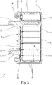
- the Figures 1 to 3 show different views of an embodiment of a battery 1.
- the battery 1 is used both to supply consumers with electrical energy and to store electrical energy generated by generators.
- the battery 1 has a plurality of cells 2 , a battery housing 3 , a first electrical cell connector 4 , a second electrical cell connector 5 , a first electrical battery terminal 6 and a second electrical battery terminal 7 .
- the battery 1 also has a battery inlet 8 and a battery outlet 9 for a temperature control medium.
- the battery case 3, which without the aforementioned other components of the battery 1 in the figures 4 and 5 is shown has a battery base 10, a battery tray 11 and a battery cover 12.
- the first battery pole 6 and the second battery pole 7 are without the other components mentioned in the beginning figure 6 shown.
- the first battery pole 6 runs through the battery inlet 8 and the second battery pole 7 runs through the battery outlet 9 .
- the battery poles 6 , 7 are bathed in a temperature control medium which cools the battery poles 6 , 7 .
- Both the battery inlet 8 and the battery outlet 9 are arranged in the battery cover 12 .
- the first battery pole 6 and the second battery pole 7 are also arranged in the battery cover 12 .
- the cells 2 are round cells.
- Each of the cells 2 has an electrical energy store and a cell housing in the form of a cylinder with a round cross-sectional contour.
- the electrical energy store is arranged in the cell housing and the cell housing encloses the electrical energy store tightly for a temperature control medium.
- each of the cells 2 has a first electrical cell contact 13 on a first surface of the cell 2 and a second electrical cell contact 14 on a second surface of the cell 2 opposite the first surface.
- the battery base 10, the battery carrier 11 and the battery cover 12 enclose a battery interior 15 apart from the battery inlet 8 and battery outlet 9 tightly for a tempering medium.
- a temperature control medium can thus only be supplied to or removed from the battery interior 15 via the battery inlet 8 and the battery outlet 9 .
- the cells 2 are arranged in the battery interior 15 to be flushed with a temperature control medium. Due to the round cross-sectional contour of the cells 2, free spaces remain between the cells 2, despite the directly adjacent arrangement of the cells 2, through which a temperature control medium can flow.
- a temperature control medium flows through the battery inlet 8 into the battery interior 15 and flows out of the battery interior 15 through the battery outlet 9 . Due to the described structure of the battery 1, a homogeneous and uniform flow around the cells 2 is given.
- the battery base 10, the battery tray 11 and the battery cover 12 are injection molded plastic components.
- the battery base 10 and the battery carrier 11 are made of different plastics and have a common base contact surface 16 .
- the ground contact surface 16 is designed as a tongue and groove. Namely, a first groove 17 is formed in the battery base 10 and a first tongue 18 is formed in the battery tray 11 .
- the battery base 10 and the battery carrier 11 are connected to one another in a materially bonded manner in the base contact area 16 by laser transmission welding.
- the battery cover 12 and the battery carrier 11 are also made of different plastics and have a common cover contact surface 19 .
- the cover contact surface 19 is also designed as a tongue and groove. Namely, a second groove 20 is formed in the battery cover 12 and a second tongue 21 is formed in the battery tray 11 .
- the battery cover 12 and the battery carrier 11 are cohesively connected to one another in the cover contact area 19 by laser transmission welding.
- the battery floor 10 has floor receptacles 22 for the cells 2, which are pins.
- the first cell connector 4 is arranged between the battery base 10 and the cells 2 .
- the first cell connector 4 points to the floor receptacles 22 matching bottom recesses 23, which are openings.
- the cells 2 and the first cell connector 4 are inserted into the bottom receptacles 22, thereby being arranged and laterally fixed.
- the sequence of battery base 10, then first cell connector 4 and then cells 2 simplifies the construction of battery 1.
- the battery carrier 11 has carrier receptacles 24 for the cells 2 on a plane opposite the battery base 10 .
- the carrier receptacles 24 have a polygonal inner cross-sectional contour in the form of a hexagonal cross-sectional contour and are all of the same design.
- the carrier receptacles 24 are therefore honeycombed.
- the design and manufacture of the battery carrier 11 are simplified by the identical design of all carrier receptacles 24.
- the cells 2 are inserted into the carrier receptacles 24, as a result of which they are arranged laterally and fixed.
- the polygonal inner cross-sectional contour of the carrier receptacles 24 in conjunction with the round cross-sectional contour of the cells 2 is advantageous since contact areas between the cells 2 and the carrier receptacles 24 are small, which means that the area of the cells 2 that is in contact with a temperature control medium is correspondingly large. Due to the arrangement of the cells 2 both in the bottom receptacles 22 and in the carrier receptacles 24, the cells 2 are completely arranged and completely fixed, so that further fixing of the cells 2 is not necessary. This applies in particular to uses of the battery 1 in environments that mean strong vibrations and shocks for the battery 1. This includes, for example, uses in mobile devices.
- the second cell connector 5 is arranged between the battery cover 12 and the cells 2 , specifically it is arranged between the carrier receptacles 24 and the battery cover 12 .
- the first cell connector 4 and the second cell connector 5 are made of sheet metal, namely stamped and formed sheet metal. In particular, the openings in the first cell connector 4 are punched.
- Each of the first cell contacts 13 and the first cell connector 4 are electrically connected to each other. Furthermore, each of the second cell contacts 14 and the second cell connector 5 are electrically connected to each other. So they are Cells 2 electrically connected in parallel. The connections are made by laser welding.
- the first cell connector 4 and the first battery pole 6 are electrically connected to one another. Furthermore, the second cell connector 5 and the second battery pole 7 are electrically connected to one another. The connections are made by laser welding. An electrical connection to the battery 1 is thus established via the first battery pole 6 and the second battery pole 7. When the battery 1 is in operation, each of the battery poles 6, 7 is connected to an electrical conductor and an electric current flows through the conductor and the battery poles 6, 7 through the battery 1.
- the first battery pole 6 is rod-shaped and has a battery pole holder 25 .
- the first battery post 6 is inserted into one of the carrier receptacles 24 with the battery post holder 25 .
- the battery 1 thus has a total of 37 cells 2 .
- the battery pole holder 25 is adapted to the carrier receptacle 24 . Accordingly, the battery pole holder 25 has a polygonal outer cross-sectional contour that matches the carrier receptacle 24 .
- the shape of the battery pole holder 25 and of the carrier receptacle 24 fixes the first battery pole 6 against twisting. This fixation is advantageous because the first battery pole 6 can be connected to another electrical conductor via a pole screw connection 26 and torques occurring when the pole screw connection 26 is tightened and loosened are absorbed by the battery carrier 11 and not by the first cell connector 4 .
- the battery pole holder 25 has a plurality of battery pole recesses 27 .
- a free battery inlet cross-sectional area 28 is determined by the battery pole holder 25 with the battery pole recesses 27 and the carrier receptacle 24, see FIG figure 7 .
- a temperature control medium flows through the battery pole recesses 27.
- the battery pole holder 25 with the battery pole recesses 27 and the carrier receptacle 24 together form a flow restrictor 29 for a temperature control medium at the battery inlet 8 in the battery 1.
- the flow restrictor 29 is therefore through the battery inlet 8 and the first battery pole 6 and a flow rate of a tempering medium is set by a shape of the first battery pole 6 .
- the second battery pole 7 is also rod-shaped and additionally has a battery pole collar 30 .
- the battery pole collar 30 and the battery carrier 11 has a form-fitting collar connection 31, so that the second battery pole 7 is fixed against twisting.
- the collar connection 31 has two collar projections 32 in the battery carrier 11 and two corresponding collar recesses 33 in the battery pole collar 30 . This fixation is advantageous because the second battery pole 7 can be connected to another electrical conductor via a pole screw connection 26 and torques occurring when the pole screw connection 26 is tightened and loosened are absorbed by the battery carrier 11 and not by the second cell connector 5 .
- a free battery drain cross-sectional area 34 is determined by the second battery pole 7 and the battery drain 9, in that the second battery pole 7 is led out through the battery drain 9, see FIG figure 8 .
- the battery outlet cross-sectional area 34 is larger than the battery inlet cross-sectional area 28 so that no excessive pressure builds up in the battery interior 15 as a result of a temperature control medium flowing through the battery interior 15 .
- the first battery pole 6, the second battery pole 7, the battery inlet 8 and the battery outlet 9 are arranged in the battery cover 12, as a result of which the handling of the battery 1 is simplified.
- the first electrical cell contacts 13 and the second electrical cell contacts 14 of the cells 2, the first cell connector 4 and the second cell connector 5 are electrical conductors and are arranged in the battery interior 15. They are therefore in direct contact with a temperature control medium which is flowing through the interior 15 of the battery. Consequently, a suitable temperature control medium is electrically insulating, so that the cells 2 are not discharged via the temperature control medium.
- the connections between the first cell contacts 13 and the first cell connector 4, the connections between the second cell contacts 14 and the second cell connector 5, the connection between the first cell connector 4 and the first battery pole 6 and the connection between the second cell connector 5 and the second battery pole 7 are surrounded by a temperature control medium flowing through the battery interior 15 and are thereby cooled. This is not unique to this embodiment, but is a fundamental feature.
- the battery pole collar 30 and the second cell connector 5 are first connected to one another in an electrically conductive manner, for example welded. Then the cells 2 in the carrier recordings 24 set and the second cell contacts 14 and the second cell connector 5 connected to each other as described. Then the rest of the second battery pole 7 and the battery pole collar 30 are connected to one another, for example welded. Then the first cell contacts 13 and the first cell connector 4 are connected to one another as described. Then, on the one hand, the battery base 10 and the battery carrier 11 and, on the other hand, the battery cover 12 and the battery carrier 11 are connected to one another as described. The bottom receptacles 22 arrange and laterally fix both the first electrical cell connector 4 and the cells 2.
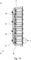
- FIG 9 shows a perspective view of an embodiment of a battery assembly 35.
- the figures 10 and 11 show different views of an exploded view of the battery assembly 35.
- the battery assembly 35 is provided both for supplying consumers with electrical energy and for storing electrical energy that is generated by generators.
- the battery assembly 35 has four batteries 1 of the embodiment described above, three electrical composite conductors 36 and a composite head 37 .
- the compound head 37 is arranged on the battery covers 12 of the batteries 1 and has a compound inlet channel 38 with a compound inlet connection 39 and a compound outlet channel 40 with a compound outlet connection 41 .
- Both the composite inlet channel 38 and the composite outlet channel 40 are each formed by a through hole through the entire composite head 37 .
- Each of the through holes is closed at one of its two ends. The respective open end opens into the compound inlet connection 39 or compound outlet connection 41.
- the first battery poles 6 and the second battery poles 7 are passed through the composite head 37 .
- the composite head 37 has pole openings 42 that match the battery poles 6 , 7 .
- the battery poles 6, 7 are accessible from the outside and from one side of the battery assembly 35, which in particular makes it easier to assemble and disassemble the composite conductors 36 and other conductors on the battery poles 6, 7.
- each of the battery inlets 8 and the compound inlet channel 38 and on the other hand each of the battery outlets 9 and the compound outlet channel 40 are connected to one another directly and tightly for a temperature control medium via interconnections 43 .
- These composite connections 43 are achieved by that the bores, which form the compound inlet duct 38 and the compound outlet duct 40, intersect the pole openings 42, so that during operation of the battery compound 35 a temperature control medium flows directly out of the bore of the compound inlet duct 38 into the battery inlets 8 and that temperature control medium flows out of the battery outlets 9 directly into the bore of the composite drain channel 40 flows.
- each of the first battery poles 6 and the composite head 37 and on the other hand each of the second battery poles 7 and the composite head 37 are sealed from one another by an O-ring seal of the first type 44 for a temperature control medium.
- These O-ring seals of the first type 44 ensure that a tempering medium cannot penetrate between the battery poles 6, 7 and the composite head 37 to the outside.
- each of the battery inlets 8 and the composite head 37 and on the other hand each of the battery outlets 9 and the composite head 37 are sealed from one another by an O-ring seal of the second type 45 for a temperature control medium.
- These O-ring seals of the second type 45 ensure that a temperature control medium cannot penetrate between the battery inlets 8 or battery outlets 9 and the composite head 37 to the outside.
- a temperature control medium flows into the compound inflow channel 38 via the compound inflow connection 39 and flows out of the compound outflow channel 40 via the compound outflow connection 41 .
- the individual batteries 1 are hydraulically connected in parallel to one another by the interconnections 43 of the battery inlets 8 with the interconnected inlet channel 38 on the one hand and the battery outlets 9 with the interconnected outlet channel 40 on the other hand, and the temperature control medium flows through each of the batteries 1. Due to the hydraulic parallel connection, the temperatures of the batteries 1 are closer together than when the batteries 1 are hydraulically connected in series, whereby a temperature distribution of the battery pack 35 is more homogeneous.
- each of the four batteries 1 and the composite head 37 are connected to one another by four composite screw connections 46, respectively.
- each of the first battery poles 6 and each of the second battery poles 7 each have a pole screw connection 26 .
- each of the pole screw connections 26 has a pole thread 47 in the battery pole 6, 7 and a pole nut 48 suitable for the pole thread 47.
- the pole screw connections 26 fix the composite head 37 and the battery cover 12 to one another and bring about a sealing effect of the O-ring seals 44, 45 described above.
- both the pole screw connections 26 and the composite screw connections 46 fix the composite head 37 and the four batteries 1 to one another.
- the four batteries 1 are electrically connected to each other through the three composite conductors 36 .
- the first battery posts 6 and the second battery posts 7 are electrically connected to each other through the composite conductors 36 such that the batteries are electrically connected in series.
- the composite conductors 36 and the battery poles 6, 7 are electrically connected to one another by the pole screw connections 26.
- each of the pole screw connections 26 has an additional pole nut 49 and the pole threads 47 are stepped, so that the composite conductors 36 lie on the battery poles 6, 7, as a result of which an electrical contact surface for conducting current is created.
- the battery assembly 35 has flow restrictors 29 so that a temperature control medium flows through each of the batteries at a sufficient flow rate.
- each of the four batteries 1 has a flow restrictor 29 .
- Each of these flow restrictors 29 is formed by the battery inlet 8 and the first battery pole 6 .
- a flow rate of such a flow restrictor 29 is set by a shape of the first battery electric terminal 6 .
- the flow restrictors 29 are additionally arranged in the composite head 37 .
- the flow restrictors 29 are formed by the composite connections 43 between the composite inlet channel 38 on the one hand and the battery inlets 8 on the other.
- a throttling effect of the flow throttles 29 is set by a free cross-sectional area of the composite connections 43 through which a temperature control medium flows.
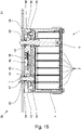
- Each of the batteries 1 has a relief vent 50 formed on an outside of the battery cover 12 .
- the overpressure opening 50 connects the battery interior 15 to an exterior 51 and is sealed by a brittle bursting disc 52 as an overpressure valve for a temperature control medium.
- the composite head 37 has an overpressure recess 53 .
- the overpressure recess 53 covers the overpressure openings 50 of Batteries 1, so that an overpressure from the batteries 1 via the overpressure openings 50 and the overpressure recess 53 to the outside into the exterior 51 can be dissipated.
- the battery assembly 35 has an electrical assembly circuit 54 with an electrical assembly interface 55 for communication with another electrical device.
- the composite circuit 54 also has a galvanic isolation 56 for communication via the composite interface 55 .
- the network circuit 54 is designed to monitor the battery network 35 and to communicate via the network interface 55 .
- the compound circuit 54 is designed to be supplied from one of the four batteries 1 and is supplied from one of the four batteries 1 of the battery system 35 during operation of the battery system 35 .
- the composite circuit 54 is implemented on a composite circuit board 57 and the composite circuit board 57 is arranged on the composite head 37 .
- the composite head 37 has a circuit board recess 58 and the composite circuit board 57 is countersunk in the circuit board recess 58 .
- the countersunk arrangement of the composite board 57 is such that it does not protrude beyond the composite head 37 outside the board recess 58 .
- the sunken arrangement of the composite board 57 protects it and the space required for the battery assembly 35 is reduced.
- the composite circuit 54 has four temperature sensors 59 and is designed to measure temperatures with the temperature sensors 59 .
- the temperature sensors 59 are designed to measure temperatures of the battery assembly 35 and are arranged on the battery assembly 35 .
- the arrangement of the temperature sensors 59 on the battery assembly 35 is such that a sensor recess 60 is formed on an outside of the battery cover 12 for each of the four batteries 1 and one of the temperature sensors 59 is arranged in the sensor recess 60 in each case.
- the design of the sensor recesses 60 in the battery covers 12 is such that a thermal resistance between the temperature sensors 59 and a temperature control medium located in the battery interiors 15 during operation of the battery assembly 35 is as low as possible.
- the compound circuit 54 is further designed to form differential temperatures from the temperatures measured with the temperature sensors 59, to compare the differential temperatures with a predetermined permissible maximum differential temperature and to detect that the maximum differential temperature is exceeded to signal. Thus, differential temperatures can be monitored.
- This configuration of the composite circuit 54 is generally given from at least two temperature sensors 59 .
- the composite circuit 54 is designed to measure a voltage and to determine and set a state of charge of each of the four batteries 1 . Specifically, the charge states of the four batteries 1 are adjusted to be equal to each other. For example, the state of charge of the batteries 1 is determined from the voltages of the batteries 1 using a characteristic curve which shows the state of charge of the batteries 1 as a function of the voltage.
Landscapes
- Chemical & Material Sciences (AREA)
- Chemical Kinetics & Catalysis (AREA)
- Electrochemistry (AREA)
- General Chemical & Material Sciences (AREA)
- Engineering & Computer Science (AREA)
- Manufacturing & Machinery (AREA)
- Microelectronics & Electronic Packaging (AREA)
- Secondary Cells (AREA)
- Battery Mounting, Suspending (AREA)
- Electric Propulsion And Braking For Vehicles (AREA)
- Heat Treatment Of Articles (AREA)
Abstract
Description
- Die Erfindung betrifft einen Batterieverbund mit mindestens zwei Batterien und mindestens einem elektrischen Verbundleiter.
- Der Batterieverbund ist sowohl für eine Versorgung von Verbrauchern mit elektrischer Energie als auch zur Speicherung von elektrischer Energie vorgesehen, die von Generatoren erzeugt wird. Der Batterieverbund ist insbesondere auch als Pufferbatterieverbund vorgesehen, also als ein Batterieverbund, der bei Ausfall eines Generators eine Versorgung von Verbrauchern übernimmt und/oder der von Generatoren erzeugte elektrische Energie zwischenspeichert, bevor sie von Verbrauchern verbraucht wird. Auch ist er zur Kompensation von Lastspitzen durch Verbraucher und/oder Erzeugungsspitzen durch Generatoren vorgesehen. Er ist geeignet, Notstromaggregate, die einen Verbrennungsmotor aufweisen, zu ersetzen. Demnach ist der Batterieverbund hochleistungsfähig. Verbraucher finden sich zum Beispiel in industriellen Anlagen in Form von Pumpen, Servern oder ganzen Rechenzentren. Generatoren sind zum Beispiel Brennstoffzellen, Fotovoltaikanlagen und Windkraftanlagen.
- Jede der Batterien weist ein Batteriegehäuse, einen ersten elektrischen Batteriepol, einen zweiten elektrischen Batteriepol, einen Batteriezulauf und einen Batterieablauf für ein Temperiermedium und mindestens eine Zelle auf.
- Jede der Zellen weist einen ersten elektrischen Zellkontakt und einen zweiten elektrischen Zellkontakt auf. Bei der mindestens einen Zelle einer jeden der Batterien sind zum einen der erste Zellkontakt und der erste Batteriepol und zum anderen der zweite Zellkontakt und der zweite Batteriepol elektrisch miteinander verbunden. Eine elektrische Verbindung mit der Batterie erfolgt über den ersten und den zweiten Batteriepol. Wenn es heißt, eine erste Komponente, wie zum Beispiel der erste Zellkontakt, und eine zweite Komponente, wie zum Beispiel der erste Batteriepol, sind elektrisch miteinander verbunden, dann ist damit gemeint, dass diese elektrisch leitend miteinander verbunden sind.
- Weiter weist jede der Zellen einen elektrischen Energiespeicher und ein Zellgehäuse auf. Der elektrische Energiespeicher ist im Zellgehäuse angeordnet und das Zellgehäuse umschließt den elektrischen Energiespeicher dicht für ein Temperiermedium. Demnach dringt ein Temperiermedium nicht in die Zelle ein. Der elektrische Energiespeicher weist einen negativen und einen positiven Pol auf. Zum Beispiel sind zum einen der negative Pol und der erste Zellkontakt und zum anderen der positive Pol und der zweite Zellkontakt elektrisch miteinander verbunden. Dann wird der erste Zellkontakt auch als Minuspol und der zweite Zellkontakt auch als Pluspol bezeichnet. Aus dem Stand der Technik bekannte Zellen sind zum Beispiel Lithium-Ionen-Zellen.
- Jedes der Batteriegehäuse weist einen Batterieboden, einen Batterieträger und einen Batteriedeckel auf. Der Batterieboden, der Batterieträger und der Batteriedeckel eines jeden der Batteriegehäuse umschließen einen Batterieinnenraum, der abgesehen vom Batteriezulauf und Batterieablauf dicht für ein Temperiermedium ist. Die Dichtigkeit des Batterieinnenraums abgesehen vom Batteriezulauf und Batterieablauf für ein Temperiermedium bedeutet, dass das Temperiermedium nur über den Batteriezulauf und den Batterieablauf dem Batterieinnenraum zugeführt oder diesem entnommen werden kann.
- Die mindestens eine Zelle einer jeden der Batterien ist im Batterieinnenraum der Batterie zur Umspülung mit einem Temperiermedium angeordnet. Die Anordnung der Zelle erfolgt dabei insbesondere durch den Batterieträger. Eine Temperatur einer Zelle muss in einem Temperaturbereich liegen, damit die Zelle zum einen ihre maximale Leistungsfähigkeit und zum anderen ihre maximale Lebensdauer erreicht. Damit die Zelle im Batteriegehäuse im Betrieb der Batterie eine Temperatur in diesem Temperaturbereich hat, wird sie von einem Temperiermedium umspült. Dabei werden eine Temperatur und eine Durchflussrate des Temperiermediums durch den Batterieinnenraum so gewählt, dass die Temperatur der Zelle in dem Temperaturbereich liegt. Ein Temperiermedium strömt durch den Batteriezulauf in den Batterieinnenraum hinein und strömt durch den Batterieablauf aus dem Batterieinnenraum hinaus.
- Die mindestens zwei Batterien sind durch den mindestens einen Verbundleiter elektrisch miteinander verbunden. Wenn der Batterieverbund vollständig elektrisch angeschlossen ist, dann sind die Batteriepole mit elektrischen Leitern verbunden. Bei den Leitern handelt es sich zum einen um den mindestens einen Verbundleiter und zum anderen um andere Leiter zum Anschluss des Batterieverbunds an eine andere Komponente. Im Betrieb des Batterieverbunds erzeugen die Energiespeicher in den Zellen einen elektrischen Strom oder nehmen eine solchen auf, sodass ein elektrischer Strom über die Leiter und die Batteriepole durch die Batterien fließt. Dabei erzeugen die Energiespeicher Wärme. Da jeder der Batteriepole und Leiter einen elektrischen Widerstand aufweist, erzeugt der Strom auch Wärme in den Batteriepolen und Leitern. Da jede der Verbindungen zwischen den Batteriepolen und den Leitern einen elektrischen Widerstand aufweist, der zumeist höher ist als die Widerstände der Batteriepole und Leiter, erzeugt der Strom in den Verbindungen auch zumeist mehr Wärme als in den Batteriepolen und Leitern. Die durch den Strom erzeugte Wärme erwärmt die Energiespeicher, die Batteriepole, Leiter und Verbindungen und führt zu einer Erhöhung der elektrischen Widerstände. Die Erwärmung kann insbesondere an den Verbindungen auch zu Beschädigungen führen.
- Aufgabe der vorliegenden Erfindung ist daher, einen Batterieverbund anzugeben, bei welchem eine Erwärmung der Batteriepole und der Verbindungen im Vergleich zum Stand der Technik reduziert ist.
- Die Aufgabe wird durch einen Batterieverbund mit den Merkmalen von Anspruch 1 gelöst. Bei diesem Batterieverbund sind bei jeder der Batterien der erste Batteriepol durch den Batteriezulauf und der zweite Batteriepol durch den Batterieablauf aus dem Batterieinnenraum nach außen geführt und sind sowohl der Batteriezulauf als auch der Batterieablauf im Batteriedeckel angeordnet. Folglich sind alle Anschlüsse einer jeden der Batterien, also der Batteriezulauf, der Batterieablauf, der erste Batteriepol und der zweite Batteriepol, im Batteriedeckel angeordnet. Dadurch sind die Anschlüsse besser zugänglich, wodurch ein Anschluss der Batterie vereinfacht ist. Hinzu kommt, dass die Batterien des Batterieverbunds für gewöhnlich derart in Bezug auf das Erdschwerefeld angeordnet sind, dass die Batteriedeckel oben sind. Dadurch ist auf einfache Weise eine automatisierte Bestückung des Batterieverbunds mit den mindestens zwei Batterien möglich, wobei nach der Bestückung der Verbundkopf aufgesetzt wird. Gleiches gilt für eine automatisierte Bestückung der mindestens zwei Batterien mit der jeweils mindestens einen Zelle. Durch die Anordnung der Batteriezuläufe und der Batterieabläufe in den Batteriedeckeln ist dann auch sichergestellt, dass ein Temperiermedium in den Batterieinnenräumen verbleibt, wenn eine Undichtigkeit außerhalb der Batterieinnenräume auftritt. Eine Undichtigkeit kann zum Beispiel an oder vor einem Batteriezulauf oder Batterieablauf auftreten. Auch wenn eine der Batterien ausläuft und dadurch ein Temperiermedium aus ihrem Batterieinnenraum ausläuft, ist gewährleistet, dass ein Temperiermedium im Batterieinnenraum der mindestens einen anderen Batterie nicht ausläuft.
- Weiter weist der Batterieverbund einen Verbundkopf auf und ist der Verbundkopf auf den Batteriedeckeln angeordnet. Der Verbundkopf weist einen Verbundzulaufkanal mit einem Verbundzulaufanschluss und einen Verbundablaufkanal mit einem Verbundablaufanschluss auf. Einerseits sind jeder der Batteriezuläufe und der Verbundzulaufkanal und andererseits jeder der Batterieabläufe und der Verbundablaufkanal unmittelbar und dicht für ein Temperiermedium miteinander verbunden. Der Batterieverbund ist abgesehen vom Verbundzulaufanschluss und vom Verbundablaufanschluss dicht für ein Temperiermedium.
- Im Betrieb des Batterieverbunds strömt ein Temperiermedium über den Verbundzulaufanschluss in den Verbundzulaufkanal hinein und strömt über den Verbundablaufanschluss aus dem Verbundablaufkanal hinaus. Durch die Verbindungen einerseits der Batteriezuläufe mit dem Verbundzulaufkanal und andererseits der Batterieabläufe mit dem Verbundablaufkanal sind die einzelnen Batterien hydraulisch parallel zueinander geschaltet und strömt das Temperiermedium durch jede der Batterien.
- Durch die hydraulische Parallelschaltung liegen Temperaturen der Batterien näher beieinander, als wenn die Batterien hydraulisch in Reihe geschaltet sind, wodurch eine Temperaturverteilung des Batterieverbunds homogener ist.
- Durch das Strömen des Temperiermediums sind die Batteriepole durch das Temperiermedium umspült, welches die Batteriepole kühlt, also in den Batteriepolen entstehende Wärme abtransportiert. Durch den Abtransport von Wärme wird eine Erwärmung der Batteriepole zumindest reduziert und dadurch auch eine Erhöhung der Widerstände der Batteriepole. Da die Batteriepole und die Leiter durch die Verbindungen auch thermisch miteinander gekoppelt sind, werden auch die Leiter und die Verbindungen gekühlt. Somit wird auch eine Temperaturverteilung der Batterien homogener, wodurch ihre Lebensdauer steigt.
- Durch die homogenere Temperaturverteilung sowohl der Batterien als auch des Batterieverbunds ist der Batterieverbund sowohl für höhere Impuls- als auch Dauerleistungen geeignet. Somit eignet sich der Batterieverbund auch für Anwendungen, die Hoch- und Höchstleistung in Bezug auf eine elektrische Kapazität des Batterieverbunds erfordern.
- Da die ersten und zweiten Zellkontakte der Zellen im Betrieb des Batterieverbunds in Kontakt mit einem Temperiermedium sind, ist ein geeignetes Temperiermedium elektrisch isolierend, sodass die Zellen nicht über das Temperiermedium entladen werden. Es kann flüssig oder gasförmig sein oder eine Mischung aus mindestens einem flüssigen und einem gasförmigen Bestandteil aufweisen. Wenn es heißt, eine Komponente, wie zum Beispiel der erste Batteriepol, ist von einem Temperiermedium umspült, dann ist damit gemeint, dass die Komponente in unmittelbaren Kontakt mit dem Temperiermedium ist.
- Aufgrund elektrochemischer Eigenschaften und Aufbauweise von Zellen entsteht im Betrieb einer Zelle am Pluspol der Zelle mehr Wärme als am Minuspol. Deshalb ist es vorteilhaft, dass der erste Batteriepol der Batterie der Minuspol und der zweite Batteriepol der Pluspol ist. Denn dann entsteht am zweiten Batteriepol mehr Wärme als am ersten Batteriepol und die am zweiten Batteriepol entstehende Wärme wird sogleich durch ein Temperiermedium von der Batterie abgeführt und nicht erst durch den Batterieinnenraum geführt, in welchem die Wärme zu einer höheren Erwärmung führt als die vom ersten Batteriepol abgeführte Wärme.
- Im Folgenden werden zunächst Ausgestaltungen und Weiterbildungen der Batterien und danach des Batterieverbunds beschrieben.
- Die Beschreibung der Ausgestaltungen und Weiterbildungen der Batterien erfolgt anhand einer Batterie, die eine Mehrzahl an Zellen aufweist. Bei jeder der Zellen ist der erste elektrische Zellkontakt auf einer ersten Fläche der Zelle und der zweite elektrische Zellkontakt auf einer der ersten Fläche gegenüberliegenden zweiten Fläche der Zelle angeordnet.
- Die Batterie weist einen ersten elektrischen Zellverbinder und einen zweiten elektrischen Zellverbinder auf. Einerseits sind jeder der ersten Zellkontakte und der erste Zellverbinder und andererseits jeder der zweiten Zellkontakte und der zweite Zellverbinder elektrisch miteinander verbunden. Dadurch sind die Zellen der Batterie elektrisch parallel geschaltet.
- Weiter sind einerseits der erste Zellverbinder und der erste Batteriepol und andererseits der zweite Zellverbinder und der zweite Batteriepol elektrisch miteinander verbunden. Die Zellkontakte und die Batteriepole sind somit mittelbar über die Zellverbinder elektrisch miteinander verbunden.
- In einer Ausgestaltung der Batterie weisen der Batteriezulauf eine freie Batteriezulaufquerschnittsfläche und der Batterieablauf eine freie Batterieablaufquerschnittsfläche auf und ist die Batteriezulaufquerschnittsfläche kleiner als die Batterieablaufquerschnittsfläche. Die freien Querschnittsflächen sind die Querschnittsflächen, durch welche ein Temperiermedium strömbar ist. Dadurch, dass der Batteriezulauf ein kleinere freie Querschnittsfläche als der Batterieablauf hat, ist gewährleistet, dass sich im Batterieinnenraum kein übermäßiger Druck durch ein durch den Batterieinnenraum strömendes Temperiermedium aufbaut.
- In einer weiteren Ausgestaltung sind die Zellen Rundzellen. Bei einer Rundzelle hat das Zellgehäuse die Form eines Zylinders mit einer runden Querschnittskontur. Der Zylinder weist eine erste und eine zweite runde Endfläche auf, die einander gegenüberliegen. Auf der ersten Endfläche ist der erste Zellkontakt und auf der zweiten Endfläche ist der zweite Zellkontakt angeordnet. Eine Verwendung von Rundzellen ist vorteilhaft, da auch bei einer unmittelbar aneinandergrenzenden Anordnung der Zellen zueinander durch die runde Querschnittskontur der Zellgehäuse Freiräume zwischen den Zellen verbleiben, durch welche ein Temperiermedium strömbar ist.
- In einer weiteren Ausgestaltung weist der Batterieboden Bodenaufnahmen für die Zellen auf und sind die Zellen in die Bodenaufnahmen eingesetzt. Vorzugsweise sind die Bodenaufnahmen Zapfen. Die Bodenaufnahmen erleichtern einen Zusammenbau der Batterie. Beim Zusammenbau der Batterie werden die Zellen zunächst in den Batterieträger eingesetzt. Dann wird der Batterieboden auf den Batterieträger gesetzt, wodurch die Zellen in die Bodenaufnahmen eingesetzt werden. Die Zellen sind dann durch die Bodenaufnahmen angeordnet und lateral fixiert.
- In einer weiteren Ausgestaltung ist der erste Zellverbinder zwischen dem Batterieboden und den Zellen angeordnet. Demnach ist der erste Zellverbinder zwischen dem Batterieboden und den ersten Zellkontakten angeordnet. Die Abfolge Batterieboden, dann erster Zellverbinder und dann Zellen vereinfacht den Aufbau der Batterie. Beim Zusammenbau der Batterie werden zunächst die Zellen in den Batterieträger eingesetzt. Dann werden die elektrischen Verbindungen zwischen dem ersten Zellverbinder und den ersten Zellkontakten hergestellt. Dann wird der Batterieboden auf den Batterieträger gesetzt. Neben den Zellen ist auch der erste Zellverbinder im Batterieinnenraum angeordnet. Folglich ist auch der erste Zellverbinder im Betrieb der Batterie von einem Temperiermedium umspült und dadurch gekühlt. Da auch jede der Verbindungen der ersten Zellkontakte und des ersten Zellverbinders und die Verbindung des ersten Zellverbinders und des ersten Batteriepols einen elektrischen Widerstand aufweist, erzeugt ein im Betrieb der Batterie fließender Strom Wärme in den Verbindungen. Dabei werden die Verbindungen vom Temperiermedium gekühlt.
- Wenn der Batterieboden Bodenaufnahmen aufweist, in welchen die Zellen eingesetzt sind, und der erste Zellverbinder zwischen dem Batterieboden und den Zellen angeordnet ist, dann ist es vorteilhaft, wenn der erste Zellverbinder zu den Bodenaufnahmen passende Bodenausnehmungen aufweist. Denn durch die Bodenausnehmungen ist der erste Zellverbinder im Batterieboden angeordnet und lateral fixiert. Wenn die Bodenaufnahmen im Batterieboden Zapfen sind, dann sind die Bodenausnehmungen im ersten Zellverbinder zu den Zapfen passende Öffnungen.
- In einer weiteren Ausgestaltung weist der Batterieträger auf einer dem Batterieboden gegenüberliegenden Ebene Trägeraufnahmen für die Zellen auf und sind die Zellen in die Trägeraufnahmen eingesetzt. Die in die Trägeraufnahmen eingesetzten Zellen sind durch die Trägeraufnahmen angeordnet und lateral fixiert. Wenn der Batterieboden Bodenaufnahmen aufweist, in welche die Zellen eingesetzt sind, und der Batterieträger auf einer dem Batterieboden gegenüberliegenden Ebene Trägeraufnahmen aufweist, in welche die Zellen ebenfalls eingesetzt sind, dann sind die Zellen im Batterieinnenraum vollständig fixiert. Somit ist eine weitere Fixierung der Zellen nicht erforderlich, wodurch der Herstellungsaufwand der Batterie reduziert ist. Insbesondere kommt kein Kleber zum Einsatz. Das ist vorteilhaft, da viele für die Fixierung geeignete Kleber nicht mit geeigneten Temperiermedien kompatibel sind. Jedenfalls ist die Kompatibilität sicherzustellen, was einen erheblichen Aufwand darstellt.
- In einer Weiterbildung der vorherigen Ausgestaltung weist der erste Batteriepol eine Batteriepolhalterung auf und ist der erste Batteriepol mit der Batteriepolhalterung in eine der Trägeraufnahmen eingesetzt. Weiter ist die Batteriepolhalterung an die Trägeraufnahme angepasst, sodass der erste Batteriepol gegen ein Verdrehen fixiert ist. Vorzugsweise ist der erste Batteriepol stabförmig ausgebildet. In dieser Weiterbildung ist anstelle einer Zelle der erste Batteriepol in eine der Trägeraufnahmen eingesetzt. Vorzugsweise sind alle Trägeraufnahmen gleich ausgebildet, sodass sowohl die Zellen als auch der erste Batteriepol in diese einsetzbar sind. Durch die gleiche Ausbildung aller Trägeraufnahmen vereinfachen sich Konstruktion und Herstellung des Batterieträgers und damit der Batterie. Eine Fixierung des ersten Batteriepols gegen ein Verdrehen ist vorteilhaft, wenn der erste Batteriepol zum Beispiel über eine Polschraubverbindung mit einem weiteren elektrischen Leiter verbunden wird, da beim Festziehen und Lösen der Schraubverbindung auftretende Drehmomente dann vom Batterieträger und nicht vom ersten Zellverbinder aufgenommen werden. Ein Drehmoment zwischen dem ersten Batteriepol und dem ersten Zellverbinder könnte die Verbindung zwischen diesen beschädigen. Eine Schraubverbindung, wie zum Beispiel eine Polschraubverbindung, von zwei Komponenten miteinander hat den Vorteil, dass die Schraubverbindung auf einfache Weise beliebig oft hergestellt und gelöst werden kann, ohne dass die Komponenten dadurch verändert werden.
- In einer Weiterbildung der vorstehenden Weiterbildung weist die Batteriepolhalterung mindestens eine Batteriepolausnehmung auf und ist die freie Batteriezulaufquerschnittsfläche durch die Batteriepolhalterung mit der mindestens einen Batteriepolausnehmung und die Trägeraufnahme bestimmt. Demnach strömt im Betrieb der Batterie ein Temperiermedium durch die mindestens eine Batteriepolausnehmung. Dadurch bilden die Batteriepolhalterung mit der mindestens einen Batteriepolausnehmung und die Trägeraufnahme eine Durchflussdrossel für ein strömendes Temperiermedium.
- Wenn der Batterieträger auf einer dem Batterieboden gegenüberliegenden Ebene Trägeraufnahmen aufweist, dann ist es vorteilhaft, wenn mindestens eine der Trägeraufnahmen eine polygone Innenquerschnittskontur aufweist. Die polygone Innenquerschnittskontur ist insbesondere in Verbindung mit Rundzellen vorteilhaft. Denn dann sind Kontaktflächen zwischen den Rundzellen und den Trägeraufnahmen klein, wodurch eine Fläche der Rundzellen entsprechend groß ist, welche mit einem Temperiermedium im Kontakt steht. Sie ist auch vorteilhaft, wenn der erste Batteriepol eine Batteriepolhalterung aufweist und die Batteriepolhalterung eine zur Trägeraufnahme passende polygone Außenquerschnittskontur aufweist. Auf diese Weise ist der erste Batteriepol gegen ein Verdrehen fixiert.
- In einer weiteren Ausgestaltung ist der zweite Zellverbinder zwischen dem Batteriedeckel und den Zellen angeordnet. Demnach ist der zweite Zellverbinder zwischen dem Batteriedeckel und den zweiten Zellkontakten angeordnet. Die Abfolge Batteriedeckel, dann zweiter Zellverbinder und dann Zellen vereinfacht den Aufbau der Batterie. Beim Zusammenbau der Batterie werden zunächst die Zellen in den Batterieträger eingesetzt. Dann werden die elektrischen Verbindungen zwischen dem zweiten Zellverbinder und den zweiten Zellkontakten hergestellt. Dann wird der Batteriedeckel auf den Batterieträger gesetzt. Der zweite Zellverbinder ist im Batterieinnenraum angeordnet. Folglich ist auch der zweite Zellverbinder im Betrieb der Batterie von einem Temperiermedium umspült und dadurch gekühlt. Da auch jede der Verbindungen der zweiten Zellkontakte und des zweiten Zellverbinders und die Verbindung des zweiten Zellverbinders und des zweiten Batteriepols einen elektrischen Widerstand aufweist, erzeugt ein im Betrieb der Batterie fließender Strom Wärme in den Verbindungen. Dabei werden die Verbindungen vom Temperiermedium gekühlt.
- Wenn der Batterieträger auf einer dem Batterieboden gegenüberliegenden Ebene Trägeraufnahmen aufweist, dann ist es vorteilhaft, die vorstehende Ausgestaltung weiterzubilden, indem der zweite Zellverbinder zwischen den Trägeraufnahmen und dem Batteriedeckel angeordnet ist. Durch die Anordnung des zweiten Zellverbinders zwischen den Trägeraufnahmen und dem Batteriedeckel wird der Aufbau der Batterie weiter vereinfacht. Der zweite Zellverbinder ist vor dem Aufsetzen des Batteriedeckels auf den Batterieträger zugänglich. Vorzugsweise weist mindestens eine der Trägeraufnahmen eine Öffnung auf, die dem zweiten Zellverbinder nur einen Zugang zum zweiten Zellkontakt und keinen Zugang zum ersten Zellkontakt einer in die Trägeraufnahme eingesetzten Zelle freigibt. Durch diese Öffnung wird sichergestellt, dass der zweite Zellverbinder keine elektrische Verbindung zu einem der ersten Zellkontakte und dadurch einen Kurzschluss herstellt. Der zweite Zellverbinder weist passend zu der mindestens einen Öffnung einen Vorsprung auf.
- In einer weiteren Ausgestaltung weist der zweite Batteriepol einen Batteriepolkragen auf. Weiter weisen der Batteriepolkragen und der Batterieträger eine formschlüssige Kragenverbindung auf, sodass der zweite Batteriepol gegen ein Verdrehen fixiert ist. Vorzugsweise ist der zweite Batteriepol stabförmig ausgebildet. Die formschlüssige Kragenverbindung ist vorteilhaft, da diese durch ein Einsetzen des zweiten Batteriepols in den Batterieträger entsteht, wodurch der Aufbau der Batterie vereinfacht ist. Eine Fixierung des zweiten Batteriepols gegen ein Verdrehen ist vorteilhaft, wenn der zweite Batteriepol zum Beispiel über eine Polschraubverbindung mit einem weiteren elektrischen Leiter verbunden wird, da beim Festziehen und Lösen der Polschraubverbindung auftretende Drehmomente vom Batterieträger und nicht vom zweiten Zellverbinder aufgenommen werden. Ein Drehmoment zwischen dem zweiten Batteriepol und dem zweiten Zellverbinder könnte die Verbindung zwischen diesen beschädigen. Vorzugsweise sind der Batteriepolkragen und der zweite Zellverbinder durch Laserschweißen miteinander verbunden.
- In einer weiteren Ausgestaltung ist von den Komponenten Batterieboden, Batterieträger und Batteriedeckel mindestens eine der Komponenten aus Kunststoff. Vorzugsweise ist eine der Komponenten eine Spritzgusskomponente. Die Verwendung von Kunststoff ist vorteilhaft, da dieser kostengünstig und einfach verarbeitbar ist. Das gilt insbesondere für Spritzgusskomponenten. Vorzugsweise ist zumindest eine der genannten Komponenten aus einem elektrisch nicht leitenden Material.
- In einer weiteren Ausgestaltung sind der Batterieboden und der Batterieträger aus voneinander verschiedenen Kunststoffen und weisen eine gemeinsame Bodenkontaktfläche auf. Weiter ist vorgesehen, dass der Batterieboden und der Batterieträger in der Bodenkontaktfläche durch Laserdurchstrahlschweißen stoffschlüssig miteinander verbunden sind. Dabei sind die Kunststoffe derart voneinander verschiedenen, dass einer der Kunststoffe für einen Laserstrahl beim Laserdurchstrahlschweißen wesentlich transparenter ist als der andere Kunststoff. Jedoch haben die Kunststoffe kompatible thermische Ausdehnungskoeffizienten, sodass mechanischen Spannungen zwischen den Komponenten aus den verschiedenen Kunststoffen akzeptabel sind. Zum Beispiel werden die verschiedenen Kunststoffe aus ähnlichen Materialgruppen ausgewählt. Beim Laserdurchstrahlschweißen wird der Laserstrahl derart geführt, dass er durch den transparenteren der beiden Kunststoffe auf den weniger transparenten der beiden Kunststoffe in der Bodenkontaktfläche trifft, den weniger transparenten der beiden Kunststoffe erhitzt, wodurch beide Kunststoffe aufgeschmolzen und auf diese Weise miteinander verschweißt werden. Eine Dichtung ist nicht erforderlich. Eine Dichtung stellt eine Schwachstelle dar. Sie kann zum Beispiel nicht ausreichend beständig gegen ein Temperiermedium sein oder durch Alterung ihre Dichtwirkung verlieren. Auch setzt eine Dichtung einen maximal zulässigen Druck im Batterieinnenraum herab.
- Vorzugsweise sind der Batterieboden und der Batterieträger in der Bodenkontaktfläche als Nut-und-Feder ausgebildet und weisen entsprechend eine Nut-und-Feder-Verbindung auf. Zum Beispiel ist die Feder im Batterieträger und ist die Nut im Batterieboden ausgebildet. Die Nut-und-Feder-Verbindung hat verschiedene Vorteile. Zum einen ist durch sie die Bodenkontaktfläche vergrößert. Zum anderen sind der Batterieboden und der Batterieträger zusammengesetzt, aber noch nicht verschweißt, lateral zueinander fixiert, wodurch das Verschweißen vereinfacht ist. Weiter ist die Fläche, in welcher der Kunststoff aufgeschmolzen wird, vergrößert, sodass die Verschweißung über eine größere Fläche erfolgt, was Stabilität und Haltbarkeit verbessert. Auch ist durch die Ausbildung als Nut-und-Feder ein höherer Druck im Batterieinnenraum möglich, da Nut und Feder sich verkeilen.
- In einer weiteren Ausgestaltung sind der Batteriedeckel und der Batterieträger aus voneinander verschiedenen Kunststoffen und weisen eine gemeinsame Deckelkontaktfläche auf. Weiter ist vorgesehen, dass der Batteriedeckel und der Batterieträger in der Deckelkontaktfläche durch Laserdurchstrahlschweißen stoffschlüssig miteinander verbunden sind. Vorzugsweise sind der Batteriedeckel und der Batterieträger in der Deckelkontaktfläche als Nut-und-Feder ausgebildet und weisen entsprechend eine Nut-und-Feder-Verbindung auf. Im Übrigen gelten die Ausführungen zur vorstehenden Ausgestaltung entsprechend.
- Das stoffschlüssige Verbinden von einerseits dem Batterieboden und dem Batterieträger und andererseits dem Batteriedeckel und dem Batterieträger weist verschiedene Vorteile auf. Ein Vorteil ist die mechanische Stabilität, wodurch die Verbindung auch starken Vibrationen und Erschütterungen standhält. Ein weiterer Vorteil ist, dass diese Verbindungen ohne weitere Dichtmittel dicht für ein Temperiermedium sind. Aus dem Stand der Technik sind Temperiermedien bekannt, insbesondere elektrisch isolierende Temperiermedien, gegen die übliche Dichtmittel nicht beständig sind. Ein fortdauernder Kontakt eines solchen Dichtmittels mit einem solchen Temperiermedium würde das Dichtmittel zerstören, das Temperiermedium kontaminieren und die Dichtigkeit des Batteriegehäuses kompromittieren. Ein weiterer Vorteil ist, dass keine weiteren Verbindungsmittel zum Herstellen der Verbindung erforderlich sind. Ein solches weiteres Verbindungsmittel wären zum Beispiel Schraubverbindungen.
- In einer weiteren Ausgestaltung ist von den Komponenten erster Zellverbinder und zweiter Zellverbinder mindestens eine der Komponenten aus einem Blech. Vorzugsweise ist eine der Komponenten aus einem gestanzten und umgeformten Blech. Ein Zellverbinder aus Blech ist vorteilhaft, da die Herstellung aus Blech einfach und kostengünstig ist. Das gilt insbesondere für einen Zellverbinder aus einem gestanzten und umgeformten Blech, da Stanzen und Umformen nur eine geringe Anzahl an Herstellungsschritten erfordert und oftmals auch in einem einzigen Herstellungsschritt umsetzbar sind. Bei kleineren Stückzahlen ist es oft vorteilhaft, das Stanzen durch Laserschneiden zu ersetzen.
- In einer weiteren Ausgestaltung sind jeder der ersten Zellkontakte und der erste Zellverbinder durch Laserschweißen miteinander verbunden. Alternativ oder zusätzlich sind jeder der zweiten Zellkontakte und der zweite Zellverbinder durch Laserschweißen miteinander verbunden. Die einzelnen Verbindungen sind dabei elektrisch leitend und stellen auch eine mechanisch stabile Verbindung in Bezug auf Vibrationen und Erschütterungen dar. Die Verbindung der Zellkontakte und der Zellverbinder durch Laserschweißen ist vorteilhaft, da das Herstellen einer solchen Verbindung nur eine kurze Zeit dauert, wodurch auch nur eine geringe Erwärmung der Zellen stattfindet. Eine übermäßige Erwärmung einer Zelle führt zu deren Beschädigung. Hinzu kommt, dass diese Verbindungen im Vergleich zu auf andere Weise hergestellten Verbindungen einen geringeren elektrischen Widerstand aufweisen. Dadurch steigen insbesondere mögliche elektrische Impulsleistungen der Batterie. Alternativen zum Laserschweißen sind Ultraschallschweißen, Widerstandsschweißen und Reibschweißen.
- In einer weiteren Ausgestaltung sind der erste Zellverbinder und der erste Batteriepol durch Laserschweißen miteinander verbunden. Alternativ oder zusätzlich sind der zweite Zellverbinder und der zweite Batteriepol durch Laserschweißen miteinander verbunden. Die Ausführungen zum Laserschweißen bei der vorstehenden Ausgestaltung gelten für diese Ausgestaltung entsprechend.
- Nachdem zuvor Ausgestaltungen und Weiterbildungen der Batterien beschrieben worden sind, folgen jetzt Ausgestaltungen und Weiterbildungen des Batterieverbunds. Der Batterieverbund weist dabei mindestens zwei der zuvor beschriebenen Batterien auf.
- In einer Ausgestaltung des Batterieverbunds sind der Verbundkopf und die Batterien miteinander verbunden. Vorzugsweise sind der Verbundkopf und die Batterien durch jeweils mindestens eine Verbundschraubverbindung miteinander verbunden. Das bedeutet, jede der Batterien und der Verbundkopf sind vorzugsweise durch mindestens eine Schraubverbindung miteinander verbunden.
- In einer weiteren Ausgestaltung weist der Batterieverbund mindestens eine Durchflussdrossel auf, sodass ein Temperiermedium durch jede der Batterien mit einer ausreichenden Durchflussrate strömt. Die mindestens eine Durchflussdrossel ist dabei dort im Batterieverbund angeordnet, wo im Betrieb des Batterieverbunds ein Temperiermedium strömt. Vorzugsweise ist eine Durchflussrate durch die Durchflussdrossel einstellbar. Das bedeutet, dass Ihre Drosselwirkung auf die Durchflussrate einstellbar ist.
- In einer Weiterbildung der vorstehenden Ausgestaltung ist die mindestens eine Durchflussdrossel im Verbundkopf angeordnet. Zum Beispiel ist die Durchflussdrossel im Verbundzulaufkanal oder im Verbundablaufkanal angeordnet. Dabei bietet sich jedoch die Anordnung der Durchflussdrossel im Verbundzulaufkanal an, da bei dieser Anordnung im Betrieb des Batterieverbunds ein Druck eines Temperiermediums in zumindest einem der Batterieinnenräume geringer ist, als wenn die Durchflussdrossel im Verbundablaufkanal angeordnet ist.
- In einer Weiterbildung der vorstehenden Ausgestaltung oder der vorstehenden Weiterbildung ist die mindestens eine Durchflussdrossel in einer der Batterien angeordnet. Wenn zum Beispiel im Verbundkopf keine Durchflussdrossel angeordnet ist, dann ist mindestens eine Durchflussdrossel in einer der Batterien angeordnet. Wenn zum Beispiel im Verbundkopf mindestens eine Durchflussdrossel angeordnet ist, dann ist mindestens eine weitere Durchflussdrossel in einer der Batterien angeordnet. Zum Beispiel ist die Durchflussdrossel am Batteriezulauf oder am Batterieablauf angeordnet. Dabei bietet sich jedoch die Anordnung der Durchflussdrossel am Batteriezulauf an, da bei dieser Anordnung im Betrieb des Batterieverbunds ein Druck eines Temperiermediums im Batterieinnenraum geringer ist, als wenn die Durchflussdrossel im Batterieablauf angeordnet ist. Vorzugsweise ist neben der mindestens einen im Verbundkopf angeordneten Durchflussdrossel mindestens eine weitere Durchflussdrossel in einer der Batterien angeordnet.
- In einer Weiterbildung der vorstehenden Weiterbildung ist die mindestens eine Durchflussdrossel zumindest teilweise durch den Batteriezulauf und den ersten Batteriepol gebildet und ist durch eine Form des ersten elektrischen Batteriepols eine Durchflussrate eines Temperiermediums eingestellt. Diese Weiterbildung ist vorteilhaft, da die Anzahl von Komponenten zur Realisierung der Durchflussdrossel reduziert ist. Hinzu kommt, dass durch die Realisierung der Durchflussdrossel am Batteriezulauf im Betrieb des Batterieverbunds ein Druck eines Temperiermediums im Batterieinnenraum geringer ist, als wenn die Durchflussdrossel im Batterieablauf angeordnet ist.
- In einer weiteren Ausgestaltung des Batterieverbunds sind die ersten Batteriepole und die zweiten Batteriepole durch Polöffnungen im Verbundkopf hindurchgeführt. Das Hindurchführen der Batteriepole durch den Verbundkopf ist vorteilhaft, da alle Batteriepole von außen und von einer Seite des Batterieverbunds zugänglich sind. Dadurch ist insbesondere ein Montieren und Demontieren des mindestens einen elektrischen Verbundleiters und weiterer Leiter an den Batteriepolen erleichtert.
- In einer Weiterbildung der vorstehenden Ausgestaltung sind einerseits jeder der ersten Batteriepole und der Verbundkopf und andererseits jeder der zweiten Batteriepole und der Verbundkopf jeweils durch eine Dichtung für ein Temperiermedium zueinander abgedichtet. Demnach sind jeder der Batteriepole und der Verbundkopf jeweils durch eine Dichtung dicht für ein Temperiermedium abgedichtet. Vorzugsweise sind die Dichtungen O-Ring-Dichtungen. Eine solche Dichtung bewirkt, dass ein Temperiermedium nicht an der Hindurchführung einer der Batteriepole durch den Verbundkopf nach außen dringen kann.
- Wenn die Batteriepole durch den Verbundkopf hindurchgeführt sind, dann ist es vorteilhaft, wenn einerseits jeder der Batteriezuläufe und der Verbundkopf und andererseits jeder der Batterieabläufe und der Verbundkopf jeweils durch eine Dichtung für ein Temperiermedium zueinander abgedichtet sind. Vorzugsweise sind auch hier die Dichtungen O-Ring-Dichtungen. Eine solche Dichtung bewirkt, dass ein Temperiermedium nicht zwischen einem der Batteriezuläufe oder Batterieabläufe und dem Verbundkopf nach außen dringen kann. O-Ring-Dichtungen gibt es aus vielen Materialien, wodurch die Wahrscheinlichkeit hoch ist, dass es ein geeignetes Material gibt. Sie sind einfach herzustellen, kostengünstig und einfach austauschbar.
- In einer Weiterbildung der vorstehenden Ausgestaltung weist jeder der ersten Batteriepole und jeder der zweiten Batteriepole jeweils eine Polschraubverbindung auf. Die Polschraubverbindungen fixieren den Verbundkopf und die Batteriedeckel zueinander und bewirken eine Dichtwirkung der Dichtungen. Zum Beispiel weist jede der Polschraubverbindungen ein Gewinde im Batteriepol und eine Mutter passend zum Gewinde im Batteriepol auf. Durch ein Festziehen der Muttern auf den Gewinden wird der Verbundkopf gegen die Batteriedeckel gepresst, wodurch sich die Dichtwirkung der Dichtungen einstellt. Wenn auch die Batteriepole und der Verbundkopf wie beschrieben jeweils durch eine Dichtung abgedichtet sind, wird durch die Polschraubverbindungen vorzugsweise auch die Dichtwirkung dieser Dichtungen hergestellt. Die Dichtwirkung ergibt sich vorzugsweise durch feste und starre Positionierung der Dichtungen.
- In einer weiteren Ausgestaltung des Batterieverbunds sind der Verbundzulaufkanal und/oder der Verbundablaufkanal jeweils zumindest teilweise durch Bohrungen bzw. durch eine Bohrung gebildet. Zum Beispiel sind sowohl der Verbundzulaufkanal als auch der Verbundablaufkanal jeweils durch eine Bohrung durch den Verbundkopf gebildet. Vorzugsweise ist jede der Bohrungen eine Durchgangsbohrung durch den ganzen Verbundkopf, welche an einem ihrer beiden Enden verschlossen ist. Wenn die Batteriepole, wie beschrieben, durch den Verbundkopf hindurchgeführt sind, dann ist es vorteilhaft, wenn die Bohrungen die Hindurchführungen der Batteriepole durch den Verbundkopf anschneiden, sodass ein Temperiermedium unmittelbar aus der Bohrung des Verbundzulaufkanals in die Batteriezuläufe strömt und das Temperiermedium aus den Batterieabläufen unmittelbar in die Bohrung des Verbundablaufkanals strömt. Die auf diese Weise hergestellten Verbindungen zwischen einerseits dem Verbundzulaufkanal und den Batteriezuläufen und andererseits dem Verbundablaufkanal und den Batterieabläufen sind vorteilhaft, da sie auf einfache Weise hergestellt sind.
- In einer weiteren Ausgestaltung sind mindestens in einem der Batteriedeckel ein erster Teil einer formschlüssigen Steckverbindung und im Verbundkopf ein zweiter Teil der formschlüssigen Verbindung ausgebildet. Dabei sind der erste Teil der formschlüssigen Verbindung und der zweite Teil der formschlüssigen Verbindung ineinander eingesetzt. Der mindestens eine Batteriedeckel und der Verbundkopf sind durch die formschlüssige Verbindung zueinander angeordnet und lateral fixiert.
- In einer weiteren Ausgestaltung verbindet der mindestens eine Verbundleiter die ersten Batteriepole und die zweiten Batteriepole miteinander, sodass die Batterien elektrisch entweder parallel oder in Reihe geschaltet sind. Wenn der Batterieverbund zum Beispiel zwei Batterien aufweist, dann sind die Batterien durch einen Verbundleiter elektrisch in Reihe oder durch zwei Verbundleiter elektrisch parallel geschaltet. Vorzugsweise sind einerseits der mindestens eine Verbundleiter und andererseits die ersten Batteriepole und die zweiten Batteriepole durch Polschraubverbindungen miteinander verbunden. Diese Ausgestaltung bietet sich insbesondere in Kombination mit Ausgestaltungen an, in welchen, wie beschrieben, Polschraubverbindungen den Verbundkopf und die Batteriedeckel zueinander fixieren und auf diese Weise Dichtwirkungen von Dichtungen bewirken.
- In einer weiteren Ausgestaltung ist auf einer Außenseite mindestens einer der Batteriedeckel eine Überdrucköffnung ausgebildet und ist die Überdrucköffnung durch eine spröde Berstscheibe als Überdruckventil dicht für ein Temperiermedium verschlossen. Weiter weist der Verbundkopf eine Überdruckausnehmung auf und überdeckt die Überdruckausnehmung die Überdrucköffnung zumindest teilweise, sodass ein Überdruck aus der Batterie über die Überdruckausnehmung abführbar ist. Die Überdrucköffnung verbindet den Batterieinnenraum mit einem Außenraum. Wenn ein Druck im Batterieinnenraum einer der Batterien einen Berstdruck überschreitet, dann birst die Berstscheibe, wodurch sie ihre Funktion als Überdruckventil erfüllt, und kann der Druck aus dem Batterieinnenraum über die Überdrucköffnung und die Überdruckausnehmung in den Außenraum entweichen.
- In einer weiteren Ausgestaltung weist der Batterieverbund eine elektrische Verbundschaltung mit einer elektrischen Verbundschnittstelle auf. Die Verbundschaltung ist zur Überwachung des Batterieverbunds und zur Kommunikation über die Verbundschnittstelle ausgebildet. Die Ausbildung der Verbundschaltung zur Überwachung des Batterieverbunds ergibt sich insbesondere daraus, dass die Verbundschaltung mindestens einen Sensor aufweist, welcher eine Größe misst, die Aufschluss über einen Zustand des Batterieverbunds gibt. Die Ausbildung der Verbundschaltung zur Kommunikation ergibt sich insbesondere daraus, dass die Verbundschaltung zur Kommunikation über die Verbundschnittstelle mit einem weiteren elektrischen Gerät ausgebildet ist. Vorzugsweise weist die Verbundschnittstelle eine galvanische Trennung für die Kommunikation auf. Wenn die elektrische Verbundschaltung über die Verbundschnittstelle mit einem weiteren elektrischen Gerät verbunden ist, dann gewährleistet die galvanische Trennung der Verbundschnittstelle, dass die Verbundschaltung und das Gerät galvanisch getrennt sind. Vorzugsweise ist die Verbundschaltung zur Versorgung aus mindestens einer der Batterien des Batterieverbunds ausgebildet. Demnach wird die Verbundschaltung im Betrieb des Batterieverbunds mit elektrischer Energie aus einer der Batterien versorgt.
- In einer Weiterbildung der vorstehenden Ausgestaltung ist die Verbundschaltung auf einer Verbundplatine realisiert und ist die Verbundplatine auf dem Verbundkopf angeordnet. Die Anordnung der Verbundplatine auf dem Verbundkopf bedeutet, dass die Verbundplatine auf dem Verbundkopf fixiert ist. Vorzugsweise weist der Verbundkopf eine Platinenausnehmung auf und ist die Verbundplatine in der Platinenausnehmung versenkt angeordnet. Durch die versenkte Anordnung der Verbundplatine ist diese geschützt und ein Platzbedarf des Batterieverbunds ist reduziert. Die versenkte Anordnung vergrößert auch den Abstand zwischen der Verbundschaltung und den Verbundleitern, sodass ein Spannungsüberschlag zwischen der Verbundschaltung und den Verbundleitern vermieden wird. Vorzugsweise sind die Verbundschaltung und die Verbundplatine mit einem Schutzlack überzogen, der sie gegen kondensierende Feuchtigkeit und Tropfen schützt.
- Wenn der Batterieverbund die beschriebene Verbundschaltung und Verbundschnittstelle aufweist, dann ist es vorteilhaft, wenn die Verbundschaltung mindestens einen Temperatursensor aufweist und die Verbundschaltung zur Messung einer Temperatur mit dem Temperatursensor ausgebildet ist. Der Temperatursensor ist zur Messung einer Temperatur des Batterieverbunds ausgebildet und am Batterieverbund angeordnet. Eine Temperatur des Batterieverbunds gibt Aufschluss über einen Zustand des Batterieverbunds, insbesondere über die Batterien und die Zellen. Vorzugsweise ist auf einer Außenseite mindestens einer der Batteriedeckel eine Sensorausnehmung ausgebildet und ist der Temperatursensor in der Sensorausnehmung angeordnet. Durch die Anordnung des Temperatursensors in der Sensorausnehmung ist dieser in diese eingesetzt. Dadurch ist der Temperatursensor zum einen geschützt. Zum anderen ist die Sensorausnehmung im Batteriedeckel derart ausgebildet, dass ein thermischer Widerstand zwischen dem Temperatursensor und einem im Betrieb des Batterieverbunds im Batterieinnenraum befindlichen Temperiermediums möglichst gering ist.
- In einer Weiterbildung weist die Verbundschaltung einen weiteren Temperatursensor auf. Weiter ist die Verbundschaltung zur Messung einer Temperatur mit dem weiteren Temperatursensor und vorzugsweise zum Vergleich mit der mit dem Temperatursensor gemessenen Temperatur ausgebildet. Ein Temperiermedium, welches im Betrieb des Batterieverbunds durch diesen strömt, darf im gesamten Batterieverbund eine Differenztemperatur nicht überschreiten. Diese Weiterbildung setzt die Erfassung von Temperaturen an verschiedenen Stellen des Batterieverbunds um, sodass Differenztemperaturen überwachbar sind. Vorzugsweise ist auf der Außenseite eines weiteren der Batteriedeckel eine Sensorausnehmung ausgebildet und ist der weitere Temperatursensor in der Sensorausnehmung angeordnet.
- Wenn der Batterieverbund die beschriebene Verbundschaltung und Verbundschnittstelle aufweist, dann ist es auch vorteilhaft, wenn die Verbundschaltung zur Messung einer Spannung mindestens einer der Batterien und/oder zum Bestimmen und/oder zum Einstellen eines Ladezustands von mindestens einer der Batterien ausgebildet ist. Sowohl das Messen der Spannung als auch das Bestimmen des Ladezustands erfolgt jeweils mittels mindestens eines Sensors, welcher eine Größe misst. Sowohl die Spannung als auch der Ladezustand geben Aufschluss über den Zustand des Batterieverbunds. Zum Zustand des Batterieverbunds gehört insbesondere auch der Ladezustand. Die Ausbildung der Verbundschaltung zum Einstellen des Ladezustands von mindestens einer der Batterien bedeutet, dass die Verbundschaltung ausgebildet ist, den Ladezustand von mindestens zwei der Batterien aneinander anzugleichen.
- Im Einzelnen ist eine Vielzahl von Möglichkeiten gegeben, den Batterieverbund auszugestalten und weiterzubilden. Dazu wird verwiesen sowohl auf die dem unabhängigen Anspruch nachgeordneten Ansprüche als auch auf die nachfolgende Beschreibung eines bevorzugten Ausführungsbeispiels in Verbindung mit der Zeichnung. In der Zeichnung zeigt
- Figur 1
- eine perspektivische Ansicht eines Ausführungsbeispiels einer Batterie eines Ausführungsbeispiels eines Batterieverbunds,
- Figur 2
- eine perspektivische Explosionsansicht der Batterie,
- Figur 3
- eine in einer Längsrichtung geschnittene Ansicht der Batterie,
- Figur 4
- eine erste perspektivische Explosionsansicht eines Batteriegehäuses der Batterie,
- Figur 5
- eine zweite perspektivische Explosionsansicht des Batteriegehäuses,
- Figur 6
- eine perspektivische Ansicht von Batteriepolen der Batterie,
- Figur 7
- eine Schnittansicht durch einen Batterieträger der Batterie,
- Figur 8
- eine Schnittansicht durch einen Batteriedeckel der Batterie,
- Figur 9
- eine perspektivische Ansicht eines Ausführungsbeispiels eines Batterieverbunds,
- Figur 10
- eine erste Ansicht einer Explosionsdarstellung des Batterieverbunds,
- Figur 11
- eine zweite Ansicht der Explosionsdarstellung,
- Figur 12
- eine in einer Längsrichtung geschnittene erste Ansicht des Batterieverbunds,
- Figur 13
- eine in einer Längsrichtung geschnittene zweite Ansicht des Batterieverbunds,
- Figur 14
- eine in einer Längsrichtung geschnittene dritte Ansicht des Batterieverbunds und
- Figur 15
- eine in einen der Querrichtung geschnittene Ansicht des Batterieverbunds.
- Die
Figuren 1 bis 3 zeigen verschiedene Ansichten eines Ausführungsbeispiels einer Batterie 1. Die Batterie 1 dient sowohl der Versorgung von Verbrauchern mit elektrischer Energie als auch zur Speicherung von elektrischer Energie, die von Generatoren erzeugt wird. Die Batterie 1 weist eine Mehrzahl an Zellen 2, ein Batteriegehäuse 3, einen ersten elektrischen Zellverbinder 4, einen zweiten elektrischen Zellverbinder 5, einen ersten elektrischen Batteriepol 6 und einen zweiten elektrischen Batteriepol 7 auf. Weiter weist die Batterie 1 einen Batteriezulauf 8 und einen Batterieablauf 9 für ein Temperiermedium auf. Das Batteriegehäuse 3, welches ohne die zuvor genannten übrigen Komponenten der Batterie 1 in denFiguren 4 und5 dargestellt ist, weist einen Batterieboden 10, einen Batterieträger 11 und einen Batteriedeckel 12 auf. Der erste Batteriepol 6 und der zweite Batteriepol 7 sind ohne die eingangs genannten übrigen Komponenten inFigur 6 dargestellt. - Der erste Batteriepol 6 ist durch den Batteriezulauf 8 geführt und der zweite Batteriepol 7 ist durch den Batterieablauf 9 geführt. Dadurch sind die Batteriepole 6, 7 im Betrieb der Batterie 1 durch ein Temperiermedium umspült, welches die Batteriepole 6, 7 kühlt. Sowohl der Batteriezulauf 8 als auch der Batterieablauf 9 sind im Batteriedeckel 12 angeordnet. Somit sind auch der erste Batteriepol 6 und der zweite Batteriepol 7 im Batteriedeckel 12 angeordnet.
- Die Zellen 2 sind Rundzellen. Jede der Zellen 2 hat einen elektrischen Energiespeicher und ein Zellgehäuse in Zylinderform mit einer runden Querschnittskontur. Der elektrische Energiespeicher ist im Zellgehäuse angeordnet und das Zellgehäuse umschließt den elektrischen Energiespeicher dicht für ein Temperiermedium. Weiter weist jede der Zellen 2 einen ersten elektrischen Zellkontakt 13 auf einer ersten Fläche der Zelle 2 und einen zweiten elektrischen Zellkontakt 14 auf einer der ersten Fläche gegenüberliegenden zweiten Fläche der Zelle 2 auf.
- Der Batterieboden 10, der Batterieträger 11 und der Batteriedeckel 12 umschließen einen Batterieinnenraum 15 abgesehen vom Batteriezulauf 8 und Batterieablauf 9 dicht für ein Temperiermedium. Somit kann ein Temperiermedium nur über den Batteriezulauf 8 und den Batterieablauf 9 dem Batterieinnenraum 15 zugeführt oder diesem entnommen werden. Die Zellen 2 sind im Batterieinnenraum 15 zur Umspülung mit einem Temperiermedium angeordnet. Durch die runde Querschnittskontur der Zellen 2 sind trotz der unmittelbar aneinandergrenzenden Anordnung der Zellen 2 Freiräume zwischen den Zellen 2 verblieben, durch welche ein Temperiermedium strömbar ist. Im Betrieb der Batterie 1 strömt ein Temperiermedium durch den Batteriezulauf 8 in den Batterieinnenraum 15 hinein und strömt durch den Batterieablauf 9 aus dem Batterieinnenraum 15 hinaus. Durch den beschriebenen Aufbau der Batterie 1 ist eine homogene und einheitliche Um strömung der Zellen 2 gegeben.
- Der Batterieboden 10, der Batterieträger 11 und der Batteriedeckel 12 sind Spritzgusskomponenten aus Kunststoff. Der Batterieboden 10 und der Batterieträger 11 sind aus voneinander verschiedenen Kunststoffen und weisen eine gemeinsame Bodenkontaktfläche 16 auf. Die Bodenkontaktfläche 16 ist als Nut-und-Feder ausgebildet. Und zwar ist eine erste Nut 17 im Batterieboden 10 und ist eine erste Feder 18 im Batterieträger 11 ausgebildet. Der Batterieboden 10 und der Batterieträger 11 sind in der Bodenkontaktfläche 16 durch Laserdurchstrahlschweißen stoffschlüssig miteinander verbunden.
- Auch der Batteriedeckel 12 und der Batterieträger 11 sind aus voneinander verschiedenen Kunststoffen und weisen eine gemeinsame Deckelkontaktfläche 19 auf. Die Deckelkontaktfläche 19 ist ebenfalls als Nut-und-Feder ausgebildet. Und zwar ist eine zweite Nut 20 im Batteriedeckel 12 und ist eine zweite Feder 21 im Batterieträger 11 ausgebildet. Der Batteriedeckel 12 und der Batterieträger 11 sind in der Deckelkontaktfläche 19 durch Laserdurchstrahlschweißen stoffschlüssig miteinander verbunden.
- Der Batterieboden 10 weist Bodenaufnahmen 22 für die Zellen 2 auf, die Zapfen sind. Der erste Zellverbinder 4 ist zwischen dem Batterieboden 10 und den Zellen 2 angeordnet. Der erste Zellverbinder 4 weist zu den Bodenaufnahmen 22 passende Bodenausnehmungen 23 auf, die Öffnungen sind. Die Zellen 2 und der erste Zellverbinder 4 sind in die Bodenaufnahmen 22 eingesetzt, wodurch sie angeordnet und lateral fixiert sind. Die Abfolge Batterieboden 10, dann erster Zellverbinder 4 und dann Zellen 2 vereinfacht den Aufbau der Batterie 1.
- Der Batterieträger 11 weist auf einer dem Batterieboden 10 gegenüberliegenden Ebene Trägeraufnahmen 24 für die Zellen 2 auf. Die Trägeraufnahmen 24 weisen eine polygone Innenquerschnittskontur in Form einer sechseckigen Querschnittskontur auf und sind alle gleich ausgebildet. Die Trägeraufnahmen 24 sind demnach wabenförmig. Durch die gleiche Ausbildung aller Trägeraufnahmen 24 vereinfachen sich Konstruktion und Herstellung des Batterieträgers 11. Die Zellen 2 sind in die Trägeraufnahmen 24 eingesetzt, wodurch sie lateral angeordnet und fixiert sind. Die polygone Innenquerschnittskontur der Trägeraufnahmen 24 in Verbindung mit der runden Querschnittskontur der Zellen 2 ist vorteilhaft, da Kontaktflächen zwischen den Zellen 2 und den Trägeraufnahmen 24 klein sind, wodurch eine Fläche der Zellen 2 entsprechend groß ist, welche mit einem Temperiermedium im Kontakt steht. Durch die Anordnung der Zellen 2 sowohl in den Bodenaufnahmen 22 als auch in den Trägeraufnahmen 24 sind die Zellen 2 vollständig angeordnet und vollständig fixiert, sodass eine weitere Fixierung der Zellen 2 nicht erforderlich ist. Das gilt insbesondere auch für Verwendungen der Batterie 1 in Umgebungen, die starke Vibrationen und Erschütterungen für die Batterie 1 bedeuten. Dazu zählen zum Beispiel Verwendungen in mobilen Vorrichtungen.
- Der zweite Zellverbinder 5 ist zwischen dem Batteriedeckel 12 und den Zellen 2 angeordnet, und zwar ist er zwischen den Trägeraufnahmen 24 und dem Batteriedeckel 12 angeordnet. Die Abfolge Batteriedeckel 12, dann zweiter Zellverbinder 5 und dann Trägeraufnahmen 24 vereinfacht den Aufbau der Batterie 1.
- Der erste Zellverbinder 4 und der zweite Zellverbinder 5 sind aus Blech, und zwar aus einem gestanzten und umgeformten Blech. Insbesondere sind die Öffnungen im ersten Zellverbinder 4 gestanzt.
- Jeder der ersten Zellkontakte 13 und der erste Zellverbinder 4 sind elektrisch miteinander verbunden. Weiter sind jeder der zweiten Zellkontakte 14 und der zweite Zellverbinder 5 elektrisch miteinander verbunden. Somit sind die Zellen 2 elektrisch parallel geschaltet. Die Verbindungen sind durch Laserschweißen hergestellt.
- Der erste Zellverbinder 4 und der erste Batteriepol 6 sind elektrisch miteinander verbunden. Weiter sind der zweite Zellverbinder 5 und der zweite Batteriepol 7 elektrisch miteinander verbunden. Die Verbindungen sind durch Laserschweißen hergestellt. Eine elektrische Verbindung mit der Batterie 1 erfolgt also über den ersten Batteriepol 6 und den zweiten Batteriepol 7. Im Betrieb der Batterie 1 ist jeder der Batteriepole 6, 7 mit einem elektrischen Leiter verbunden und fließt ein elektrischer Strom über die Leiter und die Batteriepole 6, 7 durch die Batterie 1.
- Der erste Batteriepol 6 ist stabförmig ausgebildet und weist eine Batteriepolhalterung 25 auf. Der erste Batteriepol 6 ist mit der Batteriepolhalterung 25 in eine der Trägeraufnahmen 24 eingesetzt. Somit weist die Batterie 1 insgesamt 37 Zellen 2 auf. Die Batteriepolhalterung 25 ist an die Trägeraufnahme 24 angepasst. Demnach weist die Batteriepolhalterung 25 eine zur Trägeraufnahme 24 passende polygone äußere Querschnittskontur auf. Die Formgebung von der Batteriepolhalterung 25 und von der Trägeraufnahme 24 fixiert den ersten Batteriepol 6 gegen ein Verdrehen. Diese Fixierung ist vorteilhaft, da der erste Batteriepol 6 über eine Polschraubverbindung 26 mit einem weiteren elektrischen Leiter verbindbar ist und bei einem Festziehen und Lösen der Polschraubverbindung 26 auftretende Drehmomente vom Batterieträger 11 und nicht vom ersten Zellverbinder 4 aufgenommen werden.
- Die Batteriepolhalterung 25 weist eine Mehrzahl an Batteriepolausnehmungen 27 auf. Eine freie Batteriezulaufquerschnittsfläche 28 ist durch die Batteriepolhalterung 25 mit den Batteriepolausnehmungen 27 und die Trägeraufnahme 24 bestimmt, siehe
Figur 7 . Somit strömt im Betrieb der Batterie 1 ein Temperiermedium durch die Batteriepolausnehmungen 27. Demnach bilden die Batteriepolhalterung 25 mit den Batteriepolausnehmungen 27 und die Trägeraufnahme 24 zusammen eine Durchflussdrossel 29 für ein Temperiermedium am Batteriezulauf 8 in der Batterie 1. Somit ist die Durchflussdrossel 29 durch den Batteriezulauf 8 und den ersten Batteriepol 6 gebildet und ist durch eine Form des ersten Batteriepols 6 eine Durchflussrate eines Temperiermediums eingestellt. - Der zweite Batteriepol 7 ist ebenfalls stabförmig und weist zusätzlich einen Batteriepolkragen 30 auf. Weiter weisen der Batteriepolkragen 30 und der Batterieträger 11 eine formschlüssige Kragenverbindung 31 auf, sodass der zweite Batteriepol 7 gegen ein Verdrehen fixiert ist. Die Kragenverbindung 31 weist im Batterieträger 11 zwei Kragenvorsprünge 32 und im Batteriepolkragen 30 zwei entsprechende Kragenausnehmungen 33 auf. Diese Fixierung ist vorteilhaft, da der zweite Batteriepol 7 über eine Polschraubverbindung 26 mit einem weiteren elektrischen Leiter verbindbar ist und bei einem Festziehen und Lösen der Polschraubverbindung 26 auftretende Drehmomente vom Batterieträger 11 und nicht vom zweiten Zellverbinder 5 aufgenommen werden.
- Eine freie Batterieablaufquerschnittsfläche 34 ist durch den zweiten Batteriepol 7 und den Batterieablauf 9 bestimmt, indem der zweite Batteriepol 7 durch den Batterieablauf 9 nach außen geführt ist, siehe
Figur 8 . Die Batterieablaufquerschnittsfläche 34 ist größer als die Batteriezulaufquerschnittsfläche 28, sodass sich im Batterieinnenraum 15 kein übermäßiger Druck durch ein durch den Batterieinnenraum 15 strömendes Temperiermedium aufbaut. - Der erste Batteriepol 6, der zweite Batteriepol 7, der Batteriezulauf 8 und der Batterieablauf 9 sind im Batteriedeckel 12 angeordnet, wodurch die Handhabung der Batterie 1 vereinfacht ist.
- Die ersten elektrischen Zellkontakte 13 und die zweiten elektrischen Zellkontakte 14 der Zellen 2, der erste Zellverbinder 4 und der zweite Zellverbinder 5 sind elektrische Leiter und im Batterieinnenraum 15 angeordnet. Deshalb sind sie im unmittelbaren Kontakt mit einem Temperiermedium, welches durch den Batterieinnenraum 15 geströmt wird. Folglich ist ein geeignetes Temperiermedium elektrisch isolierend, sodass die Zellen 2 nicht über das Temperiermedium entladen werden. Hinzu kommt, dass auch die Verbindungen zwischen den ersten Zellkontakten 13 und dem ersten Zellverbinder 4, die Verbindungen zwischen den zweiten Zellkontakten 14 und dem zweiten Zellverbinder 5, die Verbindung zwischen dem ersten Zellverbinder 4 und dem ersten Batteriepol 6 und die Verbindung zwischen dem zweiten Zellverbinder 5 und dem zweiten Batteriepol 7 durch ein durch den Batterieinnenraum 15 strömendes Temperiermedium umspült und dadurch gekühlt sind. Das ist nicht nur in diesem Ausführungsbeispiel der Fall, sondern ein grundlegendes Merkmal.
- Beim Zusammenbau der Batterie 1 werden zunächst der Batteriepolkragen 30 und der zweite Zellverbinder 5 elektrisch leitendend miteinander verbunden, zum Beispiel verschweißt. Dann werden die Zellen 2 in die Trägeraufnahmen 24 gesetzt und die zweiten Zellkontakte 14 und der zweite Zellverbinder 5 wie beschrieben miteinander verbunden. Dann werden der übrige zweite Batteriepol 7 und der Batteriepolkragen 30 miteinander verbunden, zum Beispiel verschweißt. Dann werden die ersten Zellkontakte 13 und der erste Zellverbinder 4 wie beschrieben miteinander verbunden. Dann werden zum einen der Batterieboden 10 und der Batterieträger 11 und zum anderen der Batteriedeckel 12 und der Batterieträger 11 wie beschrieben miteinander verbunden. Die Bodenaufnahmen 22 ordnen an und fixieren lateral dabei sowohl den ersten elektrischen Zellverbinder 4 als auch die Zellen 2.
-
Figur 9 zeigt eine perspektivische Ansicht eines Ausführungsbeispiels eines Batterieverbunds 35. DieFiguren 10 und11 zeigen unterschiedliche Ansichten einer Explosionsdarstellung des Batterieverbunds 35. Der Batterieverbund 35 ist sowohl für eine Versorgung von Verbrauchern mit elektrischer Energie als auch zur Speicherung von elektrischer Energie vorgesehen, die von Generatoren erzeugt wird. - Der Batterieverbund 35 weist vier Batterien 1 des zuvor beschriebenen Ausführungsbeispiels, drei elektrische Verbundleiter 36 und einen Verbundkopf 37 auf.
- Der Verbundkopf 37 ist auf den Batteriedeckeln 12 der Batterien 1 angeordnet und weist einen Verbundzulaufkanal 38 mit einem Verbundzulaufanschluss 39 und einen Verbundablaufkanal 40 mit einem Verbundablaufanschluss 41 auf. Sowohl der Verbundzulaufkanal 38 als auch der Verbundablaufkanal 40 sind jeweils durch eine Durchgangsbohrung durch den ganzen Verbundkopf 37 gebildet. Jede der Durchgangsbohrungen ist an einem ihrer beiden Enden verschlossen. Das jeweils offene Ende mündet im Verbundzulaufanschluss 39 bzw. Verbundablaufanschluss 41.
- Die ersten Batteriepole 6 und die zweiten Batteriepole 7 sind durch den Verbundkopf 37 hindurchgeführt. Dazu weist der Verbundkopf 37 zu den Batteriepolen 6, 7 passende Polöffnungen 42 auf. Dadurch sind die Batteriepole 6, 7 von außen und von einer Seite des Batterieverbunds 35 zugänglich, wodurch insbesondere ein Montieren und Demontieren der Verbundleiter 36 und weiterer Leiter an den Batteriepolen 6, 7 erleichtert ist.
- Einerseits sind jeder der Batteriezuläufe 8 und der Verbundzulaufkanal 38 und andererseits jeder der Batterieabläufe 9 und der Verbundablaufkanal 40 unmittelbar und dicht für ein Temperiermedium über Verbundverbindungen 43 miteinander verbunden. Diese Verbundverbindungen 43 sind dadurch erreicht, dass die Bohrungen, welche den Verbundzulaufkanal 38 und den Verbundablaufkanal 40 bilden, die Polöffnungen 42 anschneiden, sodass im Betrieb des Batterieverbunds 35 ein Temperiermedium unmittelbar aus der Bohrung des Verbundzulaufkanals 38 in die Batteriezuläufe 8 strömt und dass Temperiermedium aus den Batterieabläufen 9 unmittelbar in die Bohrung des Verbundablaufkanals 40 strömt.
- Einerseits sind jeder der ersten Batteriepole 6 und der Verbundkopf 37 und andererseits jeder der zweiten Batteriepole 7 und der Verbundkopf 37 jeweils durch eine O-Ring-Dichtung erster Art 44 für ein Temperiermedium zueinander abgedichtet. Diese O-Ring-Dichtungen erster Art 44 bewirken, dass ein Temperiermedium nicht zwischen den Batteriepolen 6, 7 und dem Verbundkopf 37 nach außen dringen kann. Weiter sind einerseits jeder der Batteriezuläufe 8 und der Verbundkopf 37 und andererseits jeder der Batterieabläufe 9 und der Verbundkopf 37 jeweils durch eine O-Ring-Dichtung zweiter Art 45 für ein Temperiermedium zueinander abgedichtet. Diese O-Ring-Dichtungen zweiter Art 45 bewirken, dass ein Temperiermedium nicht zwischen den Batteriezuläufen 8 oder Batterieabläufen 9 und dem Verbundkopf 37 nach außen dringen kann. Somit ist der Batterieverbund 35 abgesehen vom Verbundzulaufanschluss 39 und vom Verbundablaufanschluss 41 dicht für ein Temperiermedium.
- Im Betrieb des Batterieverbunds 35 strömt ein Temperiermedium über den Verbundzulaufanschluss 39 in den Verbundzulaufkanal 38 hinein und strömt über den Verbundablaufanschluss 41 aus dem Verbundablaufkanal 40 hinaus. Durch die Verbundverbindungen 43 einerseits der Batteriezuläufe 8 mit dem Verbundzulaufkanal 38 und andererseits der Batterieabläufe 9 mit dem Verbundablaufkanal 40 sind die einzelnen Batterien 1 hydraulisch parallel zueinander geschaltet und strömt das Temperiermedium durch jede der Batterien 1. Durch die hydraulische Parallelschaltung liegen Temperaturen der Batterien 1 näher beieinander, als wenn die Batterien 1 hydraulisch in Reihe geschaltet sind, wodurch eine Temperaturverteilung des Batterieverbunds 35 homogener ist.
- Jede der vier Batterien 1 und der Verbundkopf 37 sind durch jeweils vier Verbundschraubverbindungen 46 miteinander verbunden. Weiter weist, wie bereits beschrieben worden ist, jeder der ersten Batteriepole 6 und jeder der zweiten Batteriepole 7 jeweils eine Polschraubverbindung 26 auf. Und zwar weist jede der Polschraubverbindungen 26 ein Polgewinde 47 im Batteriepol 6, 7 und eine Polmutter 48 passend zum Polgewinde 47 auf. Die Polschraubverbindungen 26 fixieren den Verbundkopf 37 und die Batteriedeckel 12 zueinander und bewirken eine Dichtwirkung der zuvor beschriebenen O-Ring-Dichtungen 44, 45. Weiter fixieren sowohl die Polschraubverbindungen 26 als auch die Verbundschraubverbindungen 46 den Verbundkopf 37 und die vier Batterien 1 zueinander.
- Die vier Batterien 1 sind durch die drei Verbundleiter 36 elektrisch miteinander verbunden. Und zwar sind die ersten Batteriepole 6 und die zweiten Batteriepole 7 durch die Verbundleiter 36 derart elektrisch miteinander verbunden, sodass die Batterien elektrisch in Reihe geschaltet sind. Dabei sind die Verbundleiter 36 und die Batteriepole 6, 7 durch die Polschraubverbindungen 26 elektrisch miteinander verbunden. Dazu weist jede der Polschraubverbindungen 26 eine zusätzliche Polmutter 49 auf und sind die Polgewinde 47 gestuft, sodass die Verbundleiter 36 auf den Batteriepolen 6, 7 aufliegen, wodurch eine elektrische Kontaktfläche zur Leitung von Strom entsteht.
- Der Batterieverbund 35 weist Durchflussdrosseln 29 auf, sodass ein Temperiermedium durch jede der Batterien mit einer ausreichenden Durchflussrate strömt.
- Jede der vier Batterien 1 weist, wie bereits beschrieben worden ist, eine Durchflussdrossel 29 auf. Jede dieser Durchflussdrosseln 29 ist durch den Batteriezulauf 8 und den ersten Batteriepol 6 gebildet. Eine Durchflussrate einer solchen Durchflussdrossel 29 ist durch eine Form des ersten elektrischen Batteriepols 6 eingestellt.
- In diesem Ausführungsbeispiel sind zusätzlich im Verbundkopf 37 vier weitere Durchflussdrosseln 29 angeordnet. Und zwar sind die Durchflussdrosseln 29 durch die Verbundverbindungen 43 zwischen einerseits dem Verbundzulaufkanal 38 und andererseits den Batteriezuläufen 8 gebildet. Eine Drosselwirkung der Durchflussdrosseln 29 ist durch eine freie Querschnittsfläche der Verbundverbindungen 43 eingestellt, durch welche ein Temperiermedium strömt.
- Bei jeder der Batterien 1 ist auf einer Außenseite des Batteriedeckels 12 eine Überdrucköffnung 50 ausgebildet. Die Überdrucköffnung 50 verbindet den Batterieinnenraum 15 mit einem Außenraum 51 und ist durch eine spröde Berstscheibe 52 als Überdruckventil dicht für ein Temperiermedium verschlossen. Der Verbundkopf 37 weist eine Überdruckausnehmung 53 auf. Die Überdruckausnehmung 53 überdeckt die Überdrucköffnungen 50 der Batterien 1, sodass ein Überdruck aus den Batterien 1 über die Überdrucköffnungen 50 und die Überdruckausnehmung 53 nach außen in den Außenraum 51 abführbar ist.
- Der Batterieverbund 35 weist eine elektrische Verbundschaltung 54 mit einer elektrischen Verbundschnittstelle 55 zur Kommunikation mit einem weiteren elektrischen Gerät auf. Weiter weist die Verbundschaltung 54 eine galvanische Trennung 56 für die Kommunikation über die Verbundschnittstelle 55 auf. Die Verbundschaltung 54 ist zur Überwachung des Batterieverbunds 35 und zur Kommunikation über die Verbundschnittstelle 55 ausgebildet. Weiter ist die Verbundschaltung 54 zur Versorgung aus einer der vier Batterien 1 ausgebildet und wird im Betrieb des Batterieverbunds 35 aus einer der vier Batterien 1 des Batterieverbunds 35 versorgt.
- Die Verbundschaltung 54 ist auf einer Verbundplatine 57 realisiert und die Verbundplatine 57 ist auf dem Verbundkopf 37 angeordnet. Der Verbundkopf 37 weist eine Platinenausnehmung 58 auf und die Verbundplatine 57 ist in der Platinenausnehmung 58 versenkt angeordnet. Die versenkte Anordnung der Verbundplatine 57 ist derart, dass sie außerhalb der Platinenausnehmung 58 nicht über den Verbundkopf 37 hinausragt. Durch die versenkte Anordnung der Verbundplatine 57 ist diese geschützt und ein Platzbedarf des Batterieverbunds 35 ist reduziert.
- Die Verbundschaltung 54 weist vier Temperatursensoren 59 auf und ist zur Messung von Temperaturen mit den Temperatursensoren 59 ausgebildet. Die Temperatursensoren 59 sind zur Messung von Temperaturen des Batterieverbunds 35 ausgebildet und am Batterieverbund 35 angeordnet. Die Anordnung der Temperatursensoren 59 am Batterieverbund 35 ist derart, dass bei jeder der vier Batterien 1 auf einer Außenseite des Batteriedeckels 12 eine Sensorausnehmung 60 ausgebildet ist und jeweils einer der Temperatursensoren 59 in der Sensorausnehmung 60 angeordnet ist. Die Ausbildung der Sensorausnehmungen 60 in den Batteriedeckeln 12 ist derart, dass ein thermischer Widerstand zwischen den Temperatursensoren 59 und einem im Betrieb des Batterieverbunds 35 in den Batterieinnenräumen 15 befindlichen Temperiermediums möglichst gering ist.
- Die Verbundschaltung 54 ist weiter ausgebildet, Differenztemperaturen aus den mit den Temperatursensoren 59 gemessenen Temperaturen zu bilden, die Differenztemperaturen mit einer vorgegebenen zulässigen Maximaldifferenztemperatur zu vergleichen und ein Überschreiten der Maximaldifferenztemperatur zu signalisieren. Somit sind Differenztemperaturen überwachbar. Diese Ausbildung der Verbundschaltung 54 ist allgemein ab mindestens zwei Temperatursensoren 59 gegeben.
- Weiter ist die Verbundschaltung 54 zur Messung einer Spannung und zum Bestimmen und zum Einstellen eines Ladezustands einer jeden der vier Batterien 1 ausgebildet. Insbesondere werden die Ladezustände der vier Batterien 1 derart eingestellt, dass sie einander gleich sind. Zum Beispiel wird der Ladezustands der Batterien 1 aus den Spannungen der Batterien 1 unter Verwendung einer Kennlinie bestimmt, welche den Ladezustand der Batterien 1 in Abhängigkeit der Spannung wiedergibt.
- Wenn in der Beschreibung des Ausführungsbeispiels auf eine Mehrzahl einer Komponente in einer Figur verwiesen wird und das zur Komponente gehörige Bezugszeichen in der Figur nicht auf alle Komponenten verweist, sind dennoch alle Komponenten gemeint. Zum Beispiel wird in der Beschreibung auf die Zellen verwiesen und in
Figur 2 verweist das Bezugszeichen 2 nur auf drei der Zellen. Dennoch sind alle Zellen gemeint. -
- 1
- Batterie
- 2
- Zelle
- 3
- Batteriegehäuse
- 4
- erster elektrischer Zellverbinder
- 5
- zweiter elektrischer Zellverbinder
- 6
- erster elektrischer Batteriepol
- 7
- zweiter elektrischer Batteriepol
- 8
- Batteriezulauf
- 9
- Batterieablauf
- 10
- Batterieboden
- 11
- Batterieträger
- 12
- Batteriedeckel
- 13
- erster elektrischer Zellkontakt
- 14
- zweiter elektrischer Zellkontakt
- 15
- Batterieinnenraum
- 16
- Bodenkontaktfläche
- 17
- erste Nut
- 18
- erste Feder
- 19
- Deckelkontaktfläche
- 20
- zweite Nut
- 21
- zweite Feder
- 22
- Bodenaufnahme
- 23
- Bodenausnehmung
- 24
- Trägeraufnahme
- 25
- Batteriepolhalterung
- 26
- Polschraubverbindung
- 27
- Batteriepolausnehmung
- 28
- Batteriezulaufquerschnittsfläche
- 29
- Durchflussdrossel
- 30
- Batteriepolkragen
- 31
- Kragenverbindung
- 32
- Kragenvorsprung
- 33
- Kragenausnehmung
- 34
- Batterieablaufquerschnittsfläche
- 35
- Batterieverbund
- 36
- Verbundleiter
- 37
- Verbundkopf
- 38
- Verbundzulaufkanal
- 39
- Verbundzulaufanschluss
- 40
- Verbundablaufkanal
- 41
- Verbundablaufanschluss
- 42
- Polöffnungen
- 43
- Verbundverbindung
- 44
- O-Ring-Dichtung erster Art
- 45
- O-Ring-Dichtung zweiter Art
- 46
- Verbundschraubverbindung
- 47
- Polgewinde
- 48
- Polmutter
- 49
- zusätzliche Polmutter
- 50
- Überdrucköffnung
- 51
- Außenraum
- 52
- Berstscheibe
- 53
- Überdruckausnehmung
- 54
- elektrische Verbundschaltung
- 55
- elektrische Verbundschnittstelle
- 56
- galvanische Trennung
- 57
- Verbundplatine
- 58
- Platinenausnehmung
- 59
- Temperatursensor
- 60
- Sensorausnehmung
Claims (19)
- Batterieverbund (35) mit mindestens zwei Batterien (1) und mindestens einem elektrischen Verbundleiter (36),wobei jede der Batterien (1) ein Batteriegehäuse (3), einen ersten elektrischen Batteriepol (6), einen zweiten elektrischen Batteriepol (7), einen Batteriezulauf (8) und einen Batterieablauf (9) für ein Temperiermedium und mindestens eine Zelle (2) aufweist,wobei jedes der Batteriegehäuse (3) einen Batterieboden (10), einen Batterieträger (11) und einen Batteriedeckel (12) aufweist und der Batterieboden (10), der Batterieträger (11) und der Batteriedeckel (12) einen Batterieinnenraum (15) abgesehen vom Batteriezulauf (8) und vom Batterieablauf (9) dicht für ein Temperiermedium umschließen,wobei die mindestens eine Zelle (2) einer jeden der Batterien (1) im Batterieinnenraum (15) der Batterie (1) zur Umspülung mit einem Temperiermedium angeordnet ist undwobei die mindestens zwei Batterien (1) durch den mindestens einen Verbundleiter (36) elektrisch miteinander verbunden sind,dadurch gekennzeichnet,dass bei jeder der Batterien (1) der erste Batteriepol (6) durch den Batteriezulauf (8) und der zweite Batteriepol (7) durch den Batterieablauf (9) aus dem Batterieinnenraum (15) nach außen geführt sind und dass sowohl der Batteriezulauf (8) als auch der Batterieablauf (9) im Batteriedeckel (12) angeordnet sind,dass der Batterieverbund (35) einen Verbundkopf (37) aufweist und der Verbundkopf (37) auf den Batteriedeckeln (12) angeordnet ist,dass der Verbundkopf (37) einen Verbundzulaufkanal (38) mit einem Verbundzulaufanschluss (39) und einen Verbundablaufkanal (40) mit einem Verbundablaufanschluss (41) aufweist,dass einerseits jeder der Batteriezuläufe (8) und der Verbundzulaufkanal (38) und andererseits jeder der Batterieabläufe (9) und der Verbundablaufkanal (40) unmittelbar und dicht für ein Temperiermedium miteinander verbunden sind unddass der Batterieverbund (35) abgesehen vom Verbundzulaufanschluss (39) und vom Verbundablaufanschluss (41) dicht für ein Temperiermedium ist.
- Batterieverbund (35) nach Anspruch 1, dadurch gekennzeichnet, dass der Verbundkopf (37) und die Batterien (1) miteinander verbunden sind, vorzugsweise durch jeweils mindestens eine Verbundschraubverbindung (46).
- Batterieverbund (35) nach Anspruch 1 oder 2, dadurch gekennzeichnet, dass der Batterieverbund (35) mindestens eine Durchflussdrossel (29) aufweist, sodass ein Temperiermedium durch jede der Batterien (1) mit einer ausreichenden Durchflussrate strömt und dass vorzugsweise eine Durchflussrate durch die Durchflussdrossel (29) einstellbar ist.
- Batterieverbund (35) nach Anspruch 3, dadurch gekennzeichnet, dass die mindestens eine Durchflussdrossel (29) im Verbundkopf (37) angeordnet ist.
- Batterieverbund (35) nach Anspruch 3 oder 4, dadurch gekennzeichnet, dass die mindestens eine Durchflussdrossel (29) in einer der Batterien (1) angeordnet ist.
- Batterieverbund (35) nach Anspruch 5, dadurch gekennzeichnet, dass die mindestens eine Durchflussdrossel (29) zumindest teilweise durch den Batteriezulauf (8) und den ersten Batteriepol (6) gebildet ist und durch eine Form des ersten Batteriepols (6) eine Durchflussrate eines Temperiermediums eingestellt ist.
- Batterieverbund (35) nach einem der Ansprüche 1 bis 6, dadurch gekennzeichnet, dass die ersten Batteriepole (6) und die zweiten Batteriepole (7) durch Polöffhungen (42) im Verbundkopf (37) hindurchgeführt sind.
- Batterieverbund (35) nach Anspruch 7, dadurch gekennzeichnet, dass einerseits jeder der ersten Batteriepole (6) und der Verbundkopf (37) und andererseits jeder der zweiten Batteriepole (7) und der Verbundkopf (37) jeweils durch eine Dichtung für ein Temperiermedium zueinander abgedichtet sind und dass vorzugsweise die Dichtungen O-Ring-Dichtungen (44) sind.
- Batterieverbund (35) nach Anspruch 7 oder 8, dadurch gekennzeichnet, dass einerseits jeder der Batteriezuläufe (8) und der Verbundkopf (37) und andererseits jeder der Batterieabläufe (9) und der Verbundkopf (37) jeweils durch eine Dichtung für ein Temperiermedium zueinander abgedichtet sind und dass vorzugsweise die Dichtungen O-Ring-Dichtungen (45) sind.
- Batterieverbund (35) nach Anspruch 9, dadurch gekennzeichnet, dass jeder der ersten Batteriepole (6) und jeder der zweiten Batteriepole (7) jeweils eine Polschraubverbindung (26) aufweist, dass die Polschraubverbindungen (26) den Verbundkopf (37) und die Batteriedeckel (12) zueinander fixieren und eine Dichtwirkung der Dichtungen (44, 45) bewirken.
- Batterieverbund (35) nach einem der Ansprüche 1 bis 10, dadurch gekennzeichnet, dass der Verbundzulaufkanal (38) und/oder der Verbundablaufkanal (40) jeweils zumindest teilweise durch Bohrungen bzw. eine Bohrung gebildet sind.
- Batterieverbund (35) nach einem der Ansprüche 1 bis 11, dadurch gekennzeichnet, dass mindestens in einem der Batteriedeckel (12) ein erster Teil einer formschlüssigen Steckverbindung und im Verbundkopf (37) ein zweiter Teil der formschlüssigen Verbindung ausgebildet sind, dass der erste Teil der formschlüssigen Verbindung und der zweite Teil der formschlüssigen Verbindung ineinander eingesetzt sind und dass die formschlüssige Verbindung den mindestens einen Batteriedeckel (12) und den Verbundkopf (37) zueinander anordnet und lateral fixiert.
- Batterieverbund (35) nach einem der Ansprüche 1 bis 12, dadurch gekennzeichnet, dass der mindestens eine Verbundleiter (36) die ersten Batteriepole (6) und die zweiten Batteriepole (7) elektrisch verbindet, sodass die Batterien (1) elektrisch entweder parallel oder in Reihe geschaltet sind, und dass vorzugsweise der mindestens eine Verbundleiter (36) und die ersten Batteriepole (6) und zweiten Batteriepole (7) durch Polschraubverbindungen (26) miteinander verbunden sind.
- Batterieverbund (35) nach einem der Ansprüche 1 bis 13, dadurch gekennzeichnet, dass auf einer Außenseite mindestens einer der Batteriedeckel (12) eine Überdrucköffnung (50) ausgebildet und die Überdrucköffnung (50) durch eine spröde Berstscheibe (52) als Überdruckventil dicht für ein Temperiermedium verschlossen ist, dass der Verbundkopf (37) eine Überdruckausnehmung (53) aufweist und dass die Überdruckausnehmung (53) die Überdrucköffnung (50) zumindest teilweise überdeckt, sodass ein Überdruck aus der Batterie (1) über die Überdruckausnehmung (53) abführbar ist.
- Batterieverbund (35) nach einem der Ansprüche 1 bis 14 dadurch gekennzeichnet, dass der Batterieverbund (35) eine elektrische Verbundschaltung (54) mit einer elektrischen Verbundschnittstelle (55) aufweist, dass die Verbundschaltung (54) zur Überwachung des Batterieverbunds (35) und zur Kommunikation über die Verbundschnittstelle (55) ausgebildet ist, dass vorzugsweise die Verbundschnittstelle (55) eine galvanische Trennung (56) für die Kommunikation aufweist und dass vorzugsweise die Verbundschaltung (54) zur Versorgung aus mindestens einer der Batterien (1) ausgebildet ist.
- Batterieverbund (35) nach Anspruch 15, dadurch gekennzeichnet, dass die Verbundschaltung (54) auf einer Verbundplatine (57) realisiert ist, dass die Verbundplatine (57) auf dem Verbundkopf (37) angeordnet ist und dass vorzugsweise der Verbundkopf (37) eine Platinenausnehmung (58) aufweist und die Verbundplatine (57) in der Platinenausnehmung (58) versenkt angeordnet ist.
- Batterieverbund (35) nach Anspruch 15 oder 16, dadurch gekennzeichnet, dass die Verbundschaltung (54) mindestens einen Temperatursensor (59) aufweist, dass die Verbundschaltung (54) zur Messung einer Temperatur mit dem Temperatursensor (59) ausgebildet ist und dass vorzugsweise auf einer Außenseite mindestens einer der Batteriedeckel (12) eine Sensorausnehmung (60) ausgebildet und in der Sensorausnehmung (60) der Temperatursensor (59) angeordnet ist.
- Batterieverbund (35) nach Anspruch 17, dadurch gekennzeichnet, dass die Verbundschaltung (54) einen weiteren Temperatursensor (59) aufweist, dass die Verbundschaltung (54) zur Messung einer Temperatur mit dem weiteren Temperatursensor (59) ausgebildet ist und dass vorzugsweise auf der Außenseite eines weiteren der Batteriedeckel (12) eine Sensorausnehmung (60) ausgebildet ist und in der Sensorausnehmung (60) der weitere Temperatursensor (59) angeordnet ist.
- Batterieverbund (35) nach einem der Ansprüche 15 bis 18, dadurch gekennzeichnet, dass die Verbundschaltung (54) zur Messung einer Spannung mindestens einer der Batterien (1) und/oder zum Bestimmen und/oder zum Einstellen eines Ladezustands von mindestens einer der Batterien (1) ausgebildet ist.
Applications Claiming Priority (1)
| Application Number | Priority Date | Filing Date | Title |
|---|---|---|---|
| DE102020135025.2A DE102020135025B3 (de) | 2020-12-29 | 2020-12-29 | Batterieverbund mit mindestens zwei Batterien |
Publications (4)
| Publication Number | Publication Date |
|---|---|
| EP4024569A2 true EP4024569A2 (de) | 2022-07-06 |
| EP4024569A3 EP4024569A3 (de) | 2022-07-13 |
| EP4024569C0 EP4024569C0 (de) | 2023-10-11 |
| EP4024569B1 EP4024569B1 (de) | 2023-10-11 |
Family
ID=78408847
Family Applications (1)
| Application Number | Title | Priority Date | Filing Date |
|---|---|---|---|
| EP21217259.7A Active EP4024569B1 (de) | 2020-12-29 | 2021-12-23 | Batterieverbund mit mindestens zwei batterien |
Country Status (3)
| Country | Link |
|---|---|
| EP (1) | EP4024569B1 (de) |
| DE (1) | DE102020135025B3 (de) |
| ES (1) | ES2966480T3 (de) |
Families Citing this family (1)
| Publication number | Priority date | Publication date | Assignee | Title |
|---|---|---|---|---|
| DE102024119101A1 (de) * | 2024-07-04 | 2026-01-08 | Elringklinger Ag | Batteriemodul oder Pack und daraus aufgebautes Batteriesystem |
Family Cites Families (3)
| Publication number | Priority date | Publication date | Assignee | Title |
|---|---|---|---|---|
| DE102011016899A1 (de) * | 2011-04-13 | 2012-10-18 | Ads-Tec Gmbh | Akkupack mit einer Kühlvorrichtung |
| DE102012112294A1 (de) * | 2012-12-14 | 2014-06-18 | Dr. Ing. H.C. F. Porsche Aktiengesellschaft | Elektrischer Energiespeicher |
| DE102017102972A1 (de) * | 2017-02-15 | 2018-08-16 | Dr. Ing. H.C. F. Porsche Aktiengesellschaft | Batterieanschlusseinrichtung |
-
2020
- 2020-12-29 DE DE102020135025.2A patent/DE102020135025B3/de active Active
-
2021
- 2021-12-23 ES ES21217259T patent/ES2966480T3/es active Active
- 2021-12-23 EP EP21217259.7A patent/EP4024569B1/de active Active
Also Published As
| Publication number | Publication date |
|---|---|
| EP4024569C0 (de) | 2023-10-11 |
| DE102020135025B3 (de) | 2021-11-25 |
| EP4024569B1 (de) | 2023-10-11 |
| EP4024569A3 (de) | 2022-07-13 |
| ES2966480T3 (es) | 2024-04-22 |
Similar Documents
| Publication | Publication Date | Title |
|---|---|---|
| DE102020135026B3 (de) | Batteriesystem | |
| DE102011118383B4 (de) | Fahrzeugbatterieanordnung | |
| EP3275028B1 (de) | Batterieblock, und verfahren zur herstellung eines batterieblocks | |
| EP4024567B1 (de) | Temperierte batterie mit einer mehrzahl an zellen | |
| DE102008034868B4 (de) | Batterie mit einer in einem Batteriegehäuse angeordneten Wärmeleitplatte zum Temperieren der Batterie | |
| WO2015154910A1 (de) | Energiespeichereinheit, insbesondere batteriemodul, und energiespeichersystem mit einer mehrzahl von energiespeichereinheiten | |
| EP3363061A1 (de) | Temperiereinrichtung für ein batteriesystem | |
| WO2019161876A1 (de) | Mechanisches und thermisches system für eine modulare batterie mit leistungselektronikkomponenten | |
| DE102008010837A1 (de) | Batterie mit einer in einem Batteriegehäuse angeordneten Wärmeleitplatte zum Temperieren der Batterie | |
| DE102013015749A1 (de) | Zellblock für eine Batterie | |
| DE102013020860A1 (de) | Zellblock für eine Batterie | |
| DE102007063269A1 (de) | Batteriemodul mit mehreren Einzelzellen | |
| EP2705557A1 (de) | Lithiumsekundärzellenanordnung | |
| WO2009103466A1 (de) | Batterie mit einer in einem batteriegehäuse angeordneten wärmeleitplatte zum temperieren der batterie und verfahren zur herstellung einer batterie | |
| EP4024569B1 (de) | Batterieverbund mit mindestens zwei batterien | |
| DE102015004762A1 (de) | Batteriemodul | |
| WO2019092072A1 (de) | Modulgehäuse für ein stapelbares batteriemodul, batteriemodul sowie batteriestapel | |
| DE102021118398A1 (de) | Batterie, insbesondere für ein elektrisch angetriebenes Kraftfahrzeug | |
| DE102018000112A1 (de) | Batterie mit einer Mehrzahl von Batteriezellen | |
| EP1429406B1 (de) | Rahmenelemente für monopolare Brennstoffzellenstacks | |
| EP2909873B1 (de) | Energiespeicherzelle und energiespeichermodul | |
| DE102010062858B4 (de) | Batteriezelle | |
| WO2023110635A1 (de) | Batteriemodul mit einem modulgehäuse | |
| DE102018000232A1 (de) | Akkumulatormodul und Energiespeicher | |
| DE102007012098A1 (de) | Kondensatormodul |
Legal Events
| Date | Code | Title | Description |
|---|---|---|---|
| PUAI | Public reference made under article 153(3) epc to a published international application that has entered the european phase |
Free format text: ORIGINAL CODE: 0009012 |
|
| STAA | Information on the status of an ep patent application or granted ep patent |
Free format text: STATUS: THE APPLICATION HAS BEEN PUBLISHED |
|
| PUAL | Search report despatched |
Free format text: ORIGINAL CODE: 0009013 |
|
| AK | Designated contracting states |
Kind code of ref document: A2 Designated state(s): AL AT BE BG CH CY CZ DE DK EE ES FI FR GB GR HR HU IE IS IT LI LT LU LV MC MK MT NL NO PL PT RO RS SE SI SK SM TR |
|
| AK | Designated contracting states |
Kind code of ref document: A3 Designated state(s): AL AT BE BG CH CY CZ DE DK EE ES FI FR GB GR HR HU IE IS IT LI LT LU LV MC MK MT NL NO PL PT RO RS SE SI SK SM TR |
|
| RIC1 | Information provided on ipc code assigned before grant |
Ipc: H01M 10/48 20060101ALI20220608BHEP Ipc: H01M 10/42 20060101ALI20220608BHEP Ipc: H01M 50/569 20210101ALI20220608BHEP Ipc: H01M 50/543 20210101ALI20220608BHEP Ipc: H01M 50/342 20210101ALI20220608BHEP Ipc: H01M 50/287 20210101ALI20220608BHEP Ipc: H01M 50/271 20210101ALI20220608BHEP Ipc: H01M 50/213 20210101ALI20220608BHEP Ipc: H01M 10/6557 20140101ALI20220608BHEP Ipc: H01M 10/6553 20140101AFI20220608BHEP |
|
| STAA | Information on the status of an ep patent application or granted ep patent |
Free format text: STATUS: REQUEST FOR EXAMINATION WAS MADE |
|
| 17P | Request for examination filed |
Effective date: 20230111 |
|
| RBV | Designated contracting states (corrected) |
Designated state(s): AL AT BE BG CH CY CZ DE DK EE ES FI FR GB GR HR HU IE IS IT LI LT LU LV MC MK MT NL NO PL PT RO RS SE SI SK SM TR |
|
| GRAP | Despatch of communication of intention to grant a patent |
Free format text: ORIGINAL CODE: EPIDOSNIGR1 |
|
| STAA | Information on the status of an ep patent application or granted ep patent |
Free format text: STATUS: GRANT OF PATENT IS INTENDED |
|
| INTG | Intention to grant announced |
Effective date: 20230525 |
|
| GRAS | Grant fee paid |
Free format text: ORIGINAL CODE: EPIDOSNIGR3 |
|
| GRAA | (expected) grant |
Free format text: ORIGINAL CODE: 0009210 |
|
| STAA | Information on the status of an ep patent application or granted ep patent |
Free format text: STATUS: THE PATENT HAS BEEN GRANTED |
|
| AK | Designated contracting states |
Kind code of ref document: B1 Designated state(s): AL AT BE BG CH CY CZ DE DK EE ES FI FR GB GR HR HU IE IS IT LI LT LU LV MC MK MT NL NO PL PT RO RS SE SI SK SM TR |
|
| REG | Reference to a national code |
Ref country code: GB Ref legal event code: FG4D Free format text: NOT ENGLISH |
|
| REG | Reference to a national code |
Ref country code: CH Ref legal event code: EP |
|
| REG | Reference to a national code |
Ref country code: DE Ref legal event code: R096 Ref document number: 502021001697 Country of ref document: DE |
|
| REG | Reference to a national code |
Ref country code: IE Ref legal event code: FG4D Free format text: LANGUAGE OF EP DOCUMENT: GERMAN |
|
| U01 | Request for unitary effect filed |
Effective date: 20231108 |
|
| U07 | Unitary effect registered |
Designated state(s): AT BE BG DE DK EE FI FR IT LT LU LV MT NL PT SE SI Effective date: 20231201 |
|
| REG | Reference to a national code |
Ref country code: NO Ref legal event code: T2 Effective date: 20231011 |
|
| U20 | Renewal fee for the european patent with unitary effect paid |
Year of fee payment: 3 Effective date: 20231219 |
|
| PG25 | Lapsed in a contracting state [announced via postgrant information from national office to epo] |
Ref country code: GR Free format text: LAPSE BECAUSE OF FAILURE TO SUBMIT A TRANSLATION OF THE DESCRIPTION OR TO PAY THE FEE WITHIN THE PRESCRIBED TIME-LIMIT Effective date: 20240112 |
|
| PG25 | Lapsed in a contracting state [announced via postgrant information from national office to epo] |
Ref country code: IS Free format text: LAPSE BECAUSE OF FAILURE TO SUBMIT A TRANSLATION OF THE DESCRIPTION OR TO PAY THE FEE WITHIN THE PRESCRIBED TIME-LIMIT Effective date: 20240211 |
|
| REG | Reference to a national code |
Ref country code: ES Ref legal event code: FG2A Ref document number: 2966480 Country of ref document: ES Kind code of ref document: T3 Effective date: 20240422 |
|
| PG25 | Lapsed in a contracting state [announced via postgrant information from national office to epo] |
Ref country code: IS Free format text: LAPSE BECAUSE OF FAILURE TO SUBMIT A TRANSLATION OF THE DESCRIPTION OR TO PAY THE FEE WITHIN THE PRESCRIBED TIME-LIMIT Effective date: 20240211 Ref country code: GR Free format text: LAPSE BECAUSE OF FAILURE TO SUBMIT A TRANSLATION OF THE DESCRIPTION OR TO PAY THE FEE WITHIN THE PRESCRIBED TIME-LIMIT Effective date: 20240112 |
|
| PG25 | Lapsed in a contracting state [announced via postgrant information from national office to epo] |
Ref country code: RS Free format text: LAPSE BECAUSE OF FAILURE TO SUBMIT A TRANSLATION OF THE DESCRIPTION OR TO PAY THE FEE WITHIN THE PRESCRIBED TIME-LIMIT Effective date: 20231011 Ref country code: PL Free format text: LAPSE BECAUSE OF FAILURE TO SUBMIT A TRANSLATION OF THE DESCRIPTION OR TO PAY THE FEE WITHIN THE PRESCRIBED TIME-LIMIT Effective date: 20231011 Ref country code: HR Free format text: LAPSE BECAUSE OF FAILURE TO SUBMIT A TRANSLATION OF THE DESCRIPTION OR TO PAY THE FEE WITHIN THE PRESCRIBED TIME-LIMIT Effective date: 20231011 |
|
| REG | Reference to a national code |
Ref country code: DE Ref legal event code: R097 Ref document number: 502021001697 Country of ref document: DE |
|
| PG25 | Lapsed in a contracting state [announced via postgrant information from national office to epo] |
Ref country code: CZ Free format text: LAPSE BECAUSE OF FAILURE TO SUBMIT A TRANSLATION OF THE DESCRIPTION OR TO PAY THE FEE WITHIN THE PRESCRIBED TIME-LIMIT Effective date: 20231011 |
|
| PG25 | Lapsed in a contracting state [announced via postgrant information from national office to epo] |
Ref country code: SK Free format text: LAPSE BECAUSE OF FAILURE TO SUBMIT A TRANSLATION OF THE DESCRIPTION OR TO PAY THE FEE WITHIN THE PRESCRIBED TIME-LIMIT Effective date: 20231011 |
|
| PG25 | Lapsed in a contracting state [announced via postgrant information from national office to epo] |
Ref country code: SM Free format text: LAPSE BECAUSE OF FAILURE TO SUBMIT A TRANSLATION OF THE DESCRIPTION OR TO PAY THE FEE WITHIN THE PRESCRIBED TIME-LIMIT Effective date: 20231011 Ref country code: SK Free format text: LAPSE BECAUSE OF FAILURE TO SUBMIT A TRANSLATION OF THE DESCRIPTION OR TO PAY THE FEE WITHIN THE PRESCRIBED TIME-LIMIT Effective date: 20231011 Ref country code: RO Free format text: LAPSE BECAUSE OF FAILURE TO SUBMIT A TRANSLATION OF THE DESCRIPTION OR TO PAY THE FEE WITHIN THE PRESCRIBED TIME-LIMIT Effective date: 20231011 Ref country code: CZ Free format text: LAPSE BECAUSE OF FAILURE TO SUBMIT A TRANSLATION OF THE DESCRIPTION OR TO PAY THE FEE WITHIN THE PRESCRIBED TIME-LIMIT Effective date: 20231011 |
|
| PLBE | No opposition filed within time limit |
Free format text: ORIGINAL CODE: 0009261 |
|
| STAA | Information on the status of an ep patent application or granted ep patent |
Free format text: STATUS: NO OPPOSITION FILED WITHIN TIME LIMIT |
|
| PG25 | Lapsed in a contracting state [announced via postgrant information from national office to epo] |
Ref country code: MC Free format text: LAPSE BECAUSE OF FAILURE TO SUBMIT A TRANSLATION OF THE DESCRIPTION OR TO PAY THE FEE WITHIN THE PRESCRIBED TIME-LIMIT Effective date: 20231011 |
|
| PG25 | Lapsed in a contracting state [announced via postgrant information from national office to epo] |
Ref country code: MC Free format text: LAPSE BECAUSE OF FAILURE TO SUBMIT A TRANSLATION OF THE DESCRIPTION OR TO PAY THE FEE WITHIN THE PRESCRIBED TIME-LIMIT Effective date: 20231011 |
|
| 26N | No opposition filed |
Effective date: 20240712 |
|
| REG | Reference to a national code |
Ref country code: IE Ref legal event code: MM4A |
|
| PG25 | Lapsed in a contracting state [announced via postgrant information from national office to epo] |
Ref country code: IE Free format text: LAPSE BECAUSE OF NON-PAYMENT OF DUE FEES Effective date: 20231223 |
|
| PG25 | Lapsed in a contracting state [announced via postgrant information from national office to epo] |
Ref country code: IE Free format text: LAPSE BECAUSE OF NON-PAYMENT OF DUE FEES Effective date: 20231223 |
|
| U20 | Renewal fee for the european patent with unitary effect paid |
Year of fee payment: 4 Effective date: 20241227 |
|
| PG25 | Lapsed in a contracting state [announced via postgrant information from national office to epo] |
Ref country code: CY Free format text: LAPSE BECAUSE OF FAILURE TO SUBMIT A TRANSLATION OF THE DESCRIPTION OR TO PAY THE FEE WITHIN THE PRESCRIBED TIME-LIMIT; INVALID AB INITIO Effective date: 20211223 |
|
| PG25 | Lapsed in a contracting state [announced via postgrant information from national office to epo] |
Ref country code: TR Free format text: LAPSE BECAUSE OF FAILURE TO SUBMIT A TRANSLATION OF THE DESCRIPTION OR TO PAY THE FEE WITHIN THE PRESCRIBED TIME-LIMIT Effective date: 20231011 |
|
| REG | Reference to a national code |
Ref country code: CH Ref legal event code: U11 Free format text: ST27 STATUS EVENT CODE: U-0-0-U10-U11 (AS PROVIDED BY THE NATIONAL OFFICE) Effective date: 20260101 |
|
| PGFP | Annual fee paid to national office [announced via postgrant information from national office to epo] |
Ref country code: GB Payment date: 20251219 Year of fee payment: 5 |
|
| U20 | Renewal fee for the european patent with unitary effect paid |
Year of fee payment: 5 Effective date: 20251218 |
|
| PGFP | Annual fee paid to national office [announced via postgrant information from national office to epo] |
Ref country code: ES Payment date: 20260130 Year of fee payment: 5 |
|
| PGFP | Annual fee paid to national office [announced via postgrant information from national office to epo] |
Ref country code: NO Payment date: 20251230 Year of fee payment: 5 |
|
| PGFP | Annual fee paid to national office [announced via postgrant information from national office to epo] |
Ref country code: CH Payment date: 20260101 Year of fee payment: 5 |