EP4024550A1 - Electricity storage element and gasket - Google Patents
Electricity storage element and gasket Download PDFInfo
- Publication number
- EP4024550A1 EP4024550A1 EP20857470.7A EP20857470A EP4024550A1 EP 4024550 A1 EP4024550 A1 EP 4024550A1 EP 20857470 A EP20857470 A EP 20857470A EP 4024550 A1 EP4024550 A1 EP 4024550A1
- Authority
- EP
- European Patent Office
- Prior art keywords
- gasket
- copolymer
- power storage
- storage assembly
- experimental example
- Prior art date
- Legal status (The legal status is an assumption and is not a legal conclusion. Google has not performed a legal analysis and makes no representation as to the accuracy of the status listed.)
- Pending
Links
- 238000003860 storage Methods 0.000 title claims abstract description 95
- 230000005611 electricity Effects 0.000 title 1
- 229920001577 copolymer Polymers 0.000 claims abstract description 129
- BFKJFAAPBSQJPD-UHFFFAOYSA-N tetrafluoroethene Chemical group FC(F)=C(F)F BFKJFAAPBSQJPD-UHFFFAOYSA-N 0.000 claims abstract description 73
- 125000000524 functional group Chemical group 0.000 claims abstract description 45
- 239000000178 monomer Substances 0.000 claims abstract description 26
- 239000000155 melt Substances 0.000 claims abstract description 24
- 125000001153 fluoro group Chemical group F* 0.000 claims abstract description 18
- 125000004432 carbon atom Chemical group C* 0.000 claims abstract description 16
- 239000008151 electrolyte solution Substances 0.000 claims description 69
- 238000007789 sealing Methods 0.000 claims description 34
- 238000007906 compression Methods 0.000 claims description 30
- 230000006835 compression Effects 0.000 claims description 30
- 238000002347 injection Methods 0.000 claims description 11
- 239000007924 injection Substances 0.000 claims description 11
- 238000012546 transfer Methods 0.000 claims description 4
- OKKJLVBELUTLKV-UHFFFAOYSA-N Methanol Chemical compound OC OKKJLVBELUTLKV-UHFFFAOYSA-N 0.000 description 129
- 238000012360 testing method Methods 0.000 description 59
- KHXKESCWFMPTFT-UHFFFAOYSA-N 1,1,1,2,2,3,3-heptafluoro-3-(1,2,2-trifluoroethenoxy)propane Chemical compound FC(F)=C(F)OC(F)(F)C(F)(F)C(F)(F)F KHXKESCWFMPTFT-UHFFFAOYSA-N 0.000 description 53
- 239000008188 pellet Substances 0.000 description 43
- 238000006116 polymerization reaction Methods 0.000 description 43
- 238000001746 injection moulding Methods 0.000 description 31
- 230000000052 comparative effect Effects 0.000 description 27
- 238000000034 method Methods 0.000 description 26
- 239000000843 powder Substances 0.000 description 26
- XLYOFNOQVPJJNP-UHFFFAOYSA-N water Substances O XLYOFNOQVPJJNP-UHFFFAOYSA-N 0.000 description 26
- 239000007789 gas Substances 0.000 description 20
- YPVDWEHVCUBACK-UHFFFAOYSA-N propoxycarbonyloxy propyl carbonate Chemical compound CCCOC(=O)OOC(=O)OCCC YPVDWEHVCUBACK-UHFFFAOYSA-N 0.000 description 20
- 239000000243 solution Substances 0.000 description 20
- 229910052731 fluorine Inorganic materials 0.000 description 19
- 150000002978 peroxides Chemical class 0.000 description 19
- BCCOBQSFUDVTJQ-UHFFFAOYSA-N octafluorocyclobutane Chemical compound FC1(F)C(F)(F)C(F)(F)C1(F)F BCCOBQSFUDVTJQ-UHFFFAOYSA-N 0.000 description 18
- 235000019407 octafluorocyclobutane Nutrition 0.000 description 18
- 239000011737 fluorine Substances 0.000 description 16
- 238000010521 absorption reaction Methods 0.000 description 15
- -1 alkyl vinyl ether Chemical compound 0.000 description 15
- 238000003682 fluorination reaction Methods 0.000 description 14
- YCKRFDGAMUMZLT-UHFFFAOYSA-N Fluorine atom Chemical compound [F] YCKRFDGAMUMZLT-UHFFFAOYSA-N 0.000 description 12
- 239000000523 sample Substances 0.000 description 12
- 238000005259 measurement Methods 0.000 description 10
- 238000002844 melting Methods 0.000 description 10
- 230000008018 melting Effects 0.000 description 10
- 229910052751 metal Inorganic materials 0.000 description 10
- 239000002184 metal Substances 0.000 description 10
- 125000003178 carboxy group Chemical group [H]OC(*)=O 0.000 description 8
- 150000001875 compounds Chemical class 0.000 description 8
- 230000007797 corrosion Effects 0.000 description 8
- 238000005260 corrosion Methods 0.000 description 8
- 239000007788 liquid Substances 0.000 description 8
- 229920000642 polymer Polymers 0.000 description 7
- 238000001228 spectrum Methods 0.000 description 7
- IJGRMHOSHXDMSA-UHFFFAOYSA-N Atomic nitrogen Chemical compound N#N IJGRMHOSHXDMSA-UHFFFAOYSA-N 0.000 description 6
- OIFBSDVPJOWBCH-UHFFFAOYSA-N Diethyl carbonate Chemical compound CCOC(=O)OCC OIFBSDVPJOWBCH-UHFFFAOYSA-N 0.000 description 6
- KMTRUDSVKNLOMY-UHFFFAOYSA-N Ethylene carbonate Chemical compound O=C1OCCO1 KMTRUDSVKNLOMY-UHFFFAOYSA-N 0.000 description 6
- 238000012937 correction Methods 0.000 description 6
- 125000001028 difluoromethyl group Chemical group [H]C(F)(F)* 0.000 description 6
- 239000011521 glass Substances 0.000 description 6
- 229910052739 hydrogen Inorganic materials 0.000 description 6
- 125000001160 methoxycarbonyl group Chemical group [H]C([H])([H])OC(*)=O 0.000 description 6
- 238000005033 Fourier transform infrared spectroscopy Methods 0.000 description 5
- 239000012986 chain transfer agent Substances 0.000 description 5
- 238000006243 chemical reaction Methods 0.000 description 5
- 238000005520 cutting process Methods 0.000 description 5
- 239000000203 mixture Substances 0.000 description 5
- 230000002093 peripheral effect Effects 0.000 description 5
- 239000002904 solvent Substances 0.000 description 5
- LFQSCWFLJHTTHZ-UHFFFAOYSA-N Ethanol Chemical compound CCO LFQSCWFLJHTTHZ-UHFFFAOYSA-N 0.000 description 4
- 125000004429 atom Chemical group 0.000 description 4
- HCDGVLDPFQMKDK-UHFFFAOYSA-N hexafluoropropylene Chemical group FC(F)=C(F)C(F)(F)F HCDGVLDPFQMKDK-UHFFFAOYSA-N 0.000 description 4
- 238000007654 immersion Methods 0.000 description 4
- 239000003505 polymerization initiator Substances 0.000 description 4
- 239000007870 radical polymerization initiator Substances 0.000 description 4
- 125000006850 spacer group Chemical group 0.000 description 4
- 239000004094 surface-active agent Substances 0.000 description 4
- YMWUJEATGCHHMB-UHFFFAOYSA-N Dichloromethane Chemical compound ClCCl YMWUJEATGCHHMB-UHFFFAOYSA-N 0.000 description 3
- XEKOWRVHYACXOJ-UHFFFAOYSA-N Ethyl acetate Chemical compound CCOC(C)=O XEKOWRVHYACXOJ-UHFFFAOYSA-N 0.000 description 3
- HBBGRARXTFLTSG-UHFFFAOYSA-N Lithium ion Chemical compound [Li+] HBBGRARXTFLTSG-UHFFFAOYSA-N 0.000 description 3
- YXFVVABEGXRONW-UHFFFAOYSA-N Toluene Chemical compound CC1=CC=CC=C1 YXFVVABEGXRONW-UHFFFAOYSA-N 0.000 description 3
- 125000002252 acyl group Chemical group 0.000 description 3
- 239000003945 anionic surfactant Substances 0.000 description 3
- 230000000712 assembly Effects 0.000 description 3
- 238000000429 assembly Methods 0.000 description 3
- 229910052801 chlorine Inorganic materials 0.000 description 3
- IEJIGPNLZYLLBP-UHFFFAOYSA-N dimethyl carbonate Chemical compound COC(=O)OC IEJIGPNLZYLLBP-UHFFFAOYSA-N 0.000 description 3
- 238000001035 drying Methods 0.000 description 3
- 238000001125 extrusion Methods 0.000 description 3
- 239000000945 filler Substances 0.000 description 3
- 229910001416 lithium ion Inorganic materials 0.000 description 3
- 238000004519 manufacturing process Methods 0.000 description 3
- 238000000465 moulding Methods 0.000 description 3
- 239000011255 nonaqueous electrolyte Substances 0.000 description 3
- 125000005010 perfluoroalkyl group Chemical group 0.000 description 3
- 239000002002 slurry Substances 0.000 description 3
- 238000010557 suspension polymerization reaction Methods 0.000 description 3
- 238000001721 transfer moulding Methods 0.000 description 3
- ZILWJLIFAGWGLE-UHFFFAOYSA-N 2,2,3,3,4,4,5,5,6,6,7,7,8,8,8-pentadecafluorooctanoyl fluoride Chemical compound FC(=O)C(F)(F)C(F)(F)C(F)(F)C(F)(F)C(F)(F)C(F)(F)C(F)(F)F ZILWJLIFAGWGLE-UHFFFAOYSA-N 0.000 description 2
- YEJRWHAVMIAJKC-UHFFFAOYSA-N 4-Butyrolactone Chemical compound O=C1CCCO1 YEJRWHAVMIAJKC-UHFFFAOYSA-N 0.000 description 2
- CSCPPACGZOOCGX-UHFFFAOYSA-N Acetone Chemical compound CC(C)=O CSCPPACGZOOCGX-UHFFFAOYSA-N 0.000 description 2
- 229910000838 Al alloy Inorganic materials 0.000 description 2
- XKRFYHLGVUSROY-UHFFFAOYSA-N Argon Chemical compound [Ar] XKRFYHLGVUSROY-UHFFFAOYSA-N 0.000 description 2
- VTYYLEPIZMXCLO-UHFFFAOYSA-L Calcium carbonate Chemical compound [Ca+2].[O-]C([O-])=O VTYYLEPIZMXCLO-UHFFFAOYSA-L 0.000 description 2
- OKTJSMMVPCPJKN-UHFFFAOYSA-N Carbon Chemical compound [C] OKTJSMMVPCPJKN-UHFFFAOYSA-N 0.000 description 2
- HEDRZPFGACZZDS-UHFFFAOYSA-N Chloroform Chemical compound ClC(Cl)Cl HEDRZPFGACZZDS-UHFFFAOYSA-N 0.000 description 2
- XTHFKEDIFFGKHM-UHFFFAOYSA-N Dimethoxyethane Chemical compound COCCOC XTHFKEDIFFGKHM-UHFFFAOYSA-N 0.000 description 2
- LSDPWZHWYPCBBB-UHFFFAOYSA-N Methanethiol Chemical compound SC LSDPWZHWYPCBBB-UHFFFAOYSA-N 0.000 description 2
- PXHVJJICTQNCMI-UHFFFAOYSA-N Nickel Chemical compound [Ni] PXHVJJICTQNCMI-UHFFFAOYSA-N 0.000 description 2
- VYPSYNLAJGMNEJ-UHFFFAOYSA-N Silicium dioxide Chemical compound O=[Si]=O VYPSYNLAJGMNEJ-UHFFFAOYSA-N 0.000 description 2
- LSNNMFCWUKXFEE-UHFFFAOYSA-N Sulfurous acid Chemical compound OS(O)=O LSNNMFCWUKXFEE-UHFFFAOYSA-N 0.000 description 2
- 238000002835 absorbance Methods 0.000 description 2
- 238000000862 absorption spectrum Methods 0.000 description 2
- 229910052782 aluminium Inorganic materials 0.000 description 2
- XAGFODPZIPBFFR-UHFFFAOYSA-N aluminium Chemical compound [Al] XAGFODPZIPBFFR-UHFFFAOYSA-N 0.000 description 2
- 239000007864 aqueous solution Substances 0.000 description 2
- 230000008033 biological extinction Effects 0.000 description 2
- 229910052794 bromium Inorganic materials 0.000 description 2
- 239000003990 capacitor Substances 0.000 description 2
- 229910052799 carbon Inorganic materials 0.000 description 2
- 239000007795 chemical reaction product Substances 0.000 description 2
- NEHMKBQYUWJMIP-UHFFFAOYSA-N chloromethane Chemical compound ClC NEHMKBQYUWJMIP-UHFFFAOYSA-N 0.000 description 2
- 239000004927 clay Substances 0.000 description 2
- 238000004140 cleaning Methods 0.000 description 2
- 238000000748 compression moulding Methods 0.000 description 2
- 230000003247 decreasing effect Effects 0.000 description 2
- 230000006866 deterioration Effects 0.000 description 2
- 238000009792 diffusion process Methods 0.000 description 2
- 229910001873 dinitrogen Inorganic materials 0.000 description 2
- 239000006185 dispersion Substances 0.000 description 2
- 230000000694 effects Effects 0.000 description 2
- 239000003792 electrolyte Substances 0.000 description 2
- 238000007720 emulsion polymerization reaction Methods 0.000 description 2
- FJKIXWOMBXYWOQ-UHFFFAOYSA-N ethenoxyethane Chemical compound CCOC=C FJKIXWOMBXYWOQ-UHFFFAOYSA-N 0.000 description 2
- 125000003709 fluoroalkyl group Chemical group 0.000 description 2
- 239000011261 inert gas Substances 0.000 description 2
- 229910052740 iodine Inorganic materials 0.000 description 2
- 150000002500 ions Chemical class 0.000 description 2
- QWTDNUCVQCZILF-UHFFFAOYSA-N isopentane Chemical compound CCC(C)C QWTDNUCVQCZILF-UHFFFAOYSA-N 0.000 description 2
- AMXOYNBUYSYVKV-UHFFFAOYSA-M lithium bromide Chemical compound [Li+].[Br-] AMXOYNBUYSYVKV-UHFFFAOYSA-M 0.000 description 2
- KWGKDLIKAYFUFQ-UHFFFAOYSA-M lithium chloride Chemical compound [Li+].[Cl-] KWGKDLIKAYFUFQ-UHFFFAOYSA-M 0.000 description 2
- PQXKHYXIUOZZFA-UHFFFAOYSA-M lithium fluoride Chemical compound [Li+].[F-] PQXKHYXIUOZZFA-UHFFFAOYSA-M 0.000 description 2
- VLKZOEOYAKHREP-UHFFFAOYSA-N n-Hexane Chemical compound CCCCCC VLKZOEOYAKHREP-UHFFFAOYSA-N 0.000 description 2
- 229910052757 nitrogen Inorganic materials 0.000 description 2
- VLTRZXGMWDSKGL-UHFFFAOYSA-N perchloric acid Chemical class OCl(=O)(=O)=O VLTRZXGMWDSKGL-UHFFFAOYSA-N 0.000 description 2
- 230000000704 physical effect Effects 0.000 description 2
- 238000011084 recovery Methods 0.000 description 2
- 239000011347 resin Substances 0.000 description 2
- 229920005989 resin Polymers 0.000 description 2
- 239000003566 sealing material Substances 0.000 description 2
- 238000004904 shortening Methods 0.000 description 2
- KWVVTSALYXIJSS-UHFFFAOYSA-L silver(ii) fluoride Chemical compound [F-].[F-].[Ag+2] KWVVTSALYXIJSS-UHFFFAOYSA-L 0.000 description 2
- 238000003756 stirring Methods 0.000 description 2
- VZGDMQKNWNREIO-UHFFFAOYSA-N tetrachloromethane Chemical compound ClC(Cl)(Cl)Cl VZGDMQKNWNREIO-UHFFFAOYSA-N 0.000 description 2
- UJZCJVSSNLSCSR-UHFFFAOYSA-N (15,16,16,17,17,18,18,19,19,20,20-undecachloro-2,2,3,3,4,4,5,5,6,6,7,7,8,8,9,9,10,10,11,11,12,12,13,13,14,14,15,22,22,22-triacontafluorodocosanoyl) 15,16,16,17,17,18,18,19,19,20,20-undecachloro-2,2,3,3,4,4,5,5,6,6,7,7,8,8,9,9,10,10,11,11,12,12,13,13,14,14 Chemical compound FC(F)(F)CC(Cl)(Cl)C(Cl)(Cl)C(Cl)(Cl)C(Cl)(Cl)C(Cl)(Cl)C(F)(Cl)C(F)(F)C(F)(F)C(F)(F)C(F)(F)C(F)(F)C(F)(F)C(F)(F)C(F)(F)C(F)(F)C(F)(F)C(F)(F)C(F)(F)C(F)(F)C(=O)OOC(=O)C(F)(F)C(F)(F)C(F)(F)C(F)(F)C(F)(F)C(F)(F)C(F)(F)C(F)(F)C(F)(F)C(F)(F)C(F)(F)C(F)(F)C(F)(F)C(F)(Cl)C(Cl)(Cl)C(Cl)(Cl)C(Cl)(Cl)C(Cl)(Cl)C(Cl)(Cl)CC(F)(F)F UJZCJVSSNLSCSR-UHFFFAOYSA-N 0.000 description 1
- HBGQVKNZGOFLRH-UHFFFAOYSA-N (3,3-dichloro-2,2,4,4,4-pentafluorobutanoyl) 3,3-dichloro-2,2,4,4,4-pentafluorobutaneperoxoate Chemical compound FC(F)(F)C(Cl)(Cl)C(F)(F)C(=O)OOC(=O)C(F)(F)C(Cl)(Cl)C(F)(F)F HBGQVKNZGOFLRH-UHFFFAOYSA-N 0.000 description 1
- QFKDUYDESCLRNT-UHFFFAOYSA-N (4,5,5-trichloro-2,2,3,3,4,6,6,6-octafluorohexanoyl) 4,5,5-trichloro-2,2,3,3,4,6,6,6-octafluorohexaneperoxoate Chemical compound FC(F)(F)C(Cl)(Cl)C(F)(Cl)C(F)(F)C(F)(F)C(=O)OOC(=O)C(F)(F)C(F)(F)C(F)(Cl)C(Cl)(Cl)C(F)(F)F QFKDUYDESCLRNT-UHFFFAOYSA-N 0.000 description 1
- HLTAACNVRUAPLX-UHFFFAOYSA-N (6,6,7,7-tetrachloro-2,2,3,3,4,4,5,5,8,8,8-undecafluorooctanoyl) 6,6,7,7-tetrachloro-2,2,3,3,4,4,5,5,8,8,8-undecafluorooctaneperoxoate Chemical compound FC(F)(F)C(Cl)(Cl)C(Cl)(Cl)C(F)(F)C(F)(F)C(F)(F)C(F)(F)C(=O)OOC(=O)C(F)(F)C(F)(F)C(F)(F)C(F)(F)C(Cl)(Cl)C(Cl)(Cl)C(F)(F)F HLTAACNVRUAPLX-UHFFFAOYSA-N 0.000 description 1
- IDSJUBXWDMSMAR-UHFFFAOYSA-N (7,8,8,9,9-pentachloro-2,2,3,3,4,4,5,5,6,6,7,10,10,10-tetradecafluorodecanoyl) 7,8,8,9,9-pentachloro-2,2,3,3,4,4,5,5,6,6,7,10,10,10-tetradecafluorodecaneperoxoate Chemical compound FC(F)(F)C(Cl)(Cl)C(Cl)(Cl)C(F)(Cl)C(F)(F)C(F)(F)C(F)(F)C(F)(F)C(F)(F)C(=O)OOC(=O)C(F)(F)C(F)(F)C(F)(F)C(F)(F)C(F)(F)C(F)(Cl)C(Cl)(Cl)C(Cl)(Cl)C(F)(F)F IDSJUBXWDMSMAR-UHFFFAOYSA-N 0.000 description 1
- BLTXWCKMNMYXEA-UHFFFAOYSA-N 1,1,2-trifluoro-2-(trifluoromethoxy)ethene Chemical compound FC(F)=C(F)OC(F)(F)F BLTXWCKMNMYXEA-UHFFFAOYSA-N 0.000 description 1
- ZZXUZKXVROWEIF-UHFFFAOYSA-N 1,2-butylene carbonate Chemical compound CCC1COC(=O)O1 ZZXUZKXVROWEIF-UHFFFAOYSA-N 0.000 description 1
- LZDKZFUFMNSQCJ-UHFFFAOYSA-N 1,2-diethoxyethane Chemical compound CCOCCOCC LZDKZFUFMNSQCJ-UHFFFAOYSA-N 0.000 description 1
- HNSDLXPSAYFUHK-UHFFFAOYSA-N 1,4-bis(2-ethylhexyl) sulfosuccinate Chemical compound CCCCC(CC)COC(=O)CC(S(O)(=O)=O)C(=O)OCC(CC)CCCC HNSDLXPSAYFUHK-UHFFFAOYSA-N 0.000 description 1
- AYMDJPGTQFHDSA-UHFFFAOYSA-N 1-(2-ethenoxyethoxy)-2-ethoxyethane Chemical compound CCOCCOCCOC=C AYMDJPGTQFHDSA-UHFFFAOYSA-N 0.000 description 1
- BHNZEZWIUMJCGF-UHFFFAOYSA-N 1-chloro-1,1-difluoroethane Chemical compound CC(F)(F)Cl BHNZEZWIUMJCGF-UHFFFAOYSA-N 0.000 description 1
- 238000004293 19F NMR spectroscopy Methods 0.000 description 1
- NHJFHUKLZMQIHN-UHFFFAOYSA-N 2,2,3,3,3-pentafluoropropanoyl 2,2,3,3,3-pentafluoropropaneperoxoate Chemical compound FC(F)(F)C(F)(F)C(=O)OOC(=O)C(F)(F)C(F)(F)F NHJFHUKLZMQIHN-UHFFFAOYSA-N 0.000 description 1
- JUTIIYKOQPDNEV-UHFFFAOYSA-N 2,2,3,3,4,4,4-heptafluorobutanoyl 2,2,3,3,4,4,4-heptafluorobutaneperoxoate Chemical compound FC(F)(F)C(F)(F)C(F)(F)C(=O)OOC(=O)C(F)(F)C(F)(F)C(F)(F)F JUTIIYKOQPDNEV-UHFFFAOYSA-N 0.000 description 1
- UOFIMQWMHHYTIK-UHFFFAOYSA-N 2,2,3,3,4,4,5,5,5-nonafluoropentanoyl 2,2,3,3,4,4,5,5,5-nonafluoropentaneperoxoate Chemical compound FC(F)(F)C(F)(F)C(F)(F)C(F)(F)C(=O)OOC(=O)C(F)(F)C(F)(F)C(F)(F)C(F)(F)F UOFIMQWMHHYTIK-UHFFFAOYSA-N 0.000 description 1
- QLJQYPFKIVUSEF-UHFFFAOYSA-N 2,2,3,3,4,4,5,5,6,6,6-undecafluorohexanoyl 2,2,3,3,4,4,5,5,6,6,6-undecafluorohexaneperoxoate Chemical compound FC(F)(F)C(F)(F)C(F)(F)C(F)(F)C(F)(F)C(=O)OOC(=O)C(F)(F)C(F)(F)C(F)(F)C(F)(F)C(F)(F)F QLJQYPFKIVUSEF-UHFFFAOYSA-N 0.000 description 1
- LFCQGZXAGWRTAL-UHFFFAOYSA-N 2,2,3,3,4,4,5,5,6,6,7,7,7-tridecafluoroheptanoyl 2,2,3,3,4,4,5,5,6,6,7,7,7-tridecafluoroheptaneperoxoate Chemical compound FC(F)(F)C(F)(F)C(F)(F)C(F)(F)C(F)(F)C(F)(F)C(=O)OOC(=O)C(F)(F)C(F)(F)C(F)(F)C(F)(F)C(F)(F)C(F)(F)F LFCQGZXAGWRTAL-UHFFFAOYSA-N 0.000 description 1
- YQIZLPIUOAXZKA-UHFFFAOYSA-N 2,2,3,3,4,4,5,5,6,6,7,7,8,8,8-pentadecafluorooctanoyl 2,2,3,3,4,4,5,5,6,6,7,7,8,8,8-pentadecafluorooctaneperoxoate Chemical compound FC(F)(F)C(F)(F)C(F)(F)C(F)(F)C(F)(F)C(F)(F)C(F)(F)C(=O)OOC(=O)C(F)(F)C(F)(F)C(F)(F)C(F)(F)C(F)(F)C(F)(F)C(F)(F)F YQIZLPIUOAXZKA-UHFFFAOYSA-N 0.000 description 1
- BECCBTJLCWDIHG-UHFFFAOYSA-N 2,2,3,3,4,4,5,5,6,6,7,7,8,8,9,9,9-heptadecafluorononanoyl 2,2,3,3,4,4,5,5,6,6,7,7,8,8,9,9,9-heptadecafluorononaneperoxoate Chemical compound FC(F)(F)C(F)(F)C(F)(F)C(F)(F)C(F)(F)C(F)(F)C(F)(F)C(F)(F)C(=O)OOC(=O)C(F)(F)C(F)(F)C(F)(F)C(F)(F)C(F)(F)C(F)(F)C(F)(F)C(F)(F)F BECCBTJLCWDIHG-UHFFFAOYSA-N 0.000 description 1
- AQHKYFLVHBIQMS-UHFFFAOYSA-N 2-[difluoro(methoxy)methyl]-1,1,1,3,3,3-hexafluoropropane Chemical compound COC(F)(F)C(C(F)(F)F)C(F)(F)F AQHKYFLVHBIQMS-UHFFFAOYSA-N 0.000 description 1
- VGZZAZYCLRYTNQ-UHFFFAOYSA-N 2-ethoxyethoxycarbonyloxy 2-ethoxyethyl carbonate Chemical compound CCOCCOC(=O)OOC(=O)OCCOCC VGZZAZYCLRYTNQ-UHFFFAOYSA-N 0.000 description 1
- MKTOIPPVFPJEQO-UHFFFAOYSA-N 4-(3-carboxypropanoylperoxy)-4-oxobutanoic acid Chemical compound OC(=O)CCC(=O)OOC(=O)CCC(O)=O MKTOIPPVFPJEQO-UHFFFAOYSA-N 0.000 description 1
- 239000005995 Aluminium silicate Substances 0.000 description 1
- 229910052582 BN Inorganic materials 0.000 description 1
- PZNSFCLAULLKQX-UHFFFAOYSA-N Boron nitride Chemical compound N#B PZNSFCLAULLKQX-UHFFFAOYSA-N 0.000 description 1
- DKPFZGUDAPQIHT-UHFFFAOYSA-N Butyl acetate Natural products CCCCOC(C)=O DKPFZGUDAPQIHT-UHFFFAOYSA-N 0.000 description 1
- 229910001558 CF3SO3Li Inorganic materials 0.000 description 1
- 229910021583 Cobalt(III) fluoride Inorganic materials 0.000 description 1
- RYGMFSIKBFXOCR-UHFFFAOYSA-N Copper Chemical compound [Cu] RYGMFSIKBFXOCR-UHFFFAOYSA-N 0.000 description 1
- 229910000881 Cu alloy Inorganic materials 0.000 description 1
- XDTMQSROBMDMFD-UHFFFAOYSA-N Cyclohexane Chemical compound C1CCCCC1 XDTMQSROBMDMFD-UHFFFAOYSA-N 0.000 description 1
- RWSOTUBLDIXVET-UHFFFAOYSA-N Dihydrogen sulfide Chemical class S RWSOTUBLDIXVET-UHFFFAOYSA-N 0.000 description 1
- OTMSDBZUPAUEDD-UHFFFAOYSA-N Ethane Chemical compound CC OTMSDBZUPAUEDD-UHFFFAOYSA-N 0.000 description 1
- UFHFLCQGNIYNRP-UHFFFAOYSA-N Hydrogen Chemical compound [H][H] UFHFLCQGNIYNRP-UHFFFAOYSA-N 0.000 description 1
- 238000004566 IR spectroscopy Methods 0.000 description 1
- 229910001290 LiPF6 Inorganic materials 0.000 description 1
- NIPNSKYNPDTRPC-UHFFFAOYSA-N N-[2-oxo-2-(2,4,6,7-tetrahydrotriazolo[4,5-c]pyridin-5-yl)ethyl]-2-[[3-(trifluoromethoxy)phenyl]methylamino]pyrimidine-5-carboxamide Chemical compound O=C(CNC(=O)C=1C=NC(=NC=1)NCC1=CC(=CC=C1)OC(F)(F)F)N1CC2=C(CC1)NN=N2 NIPNSKYNPDTRPC-UHFFFAOYSA-N 0.000 description 1
- 238000005481 NMR spectroscopy Methods 0.000 description 1
- CTQNGGLPUBDAKN-UHFFFAOYSA-N O-Xylene Chemical compound CC1=CC=CC=C1C CTQNGGLPUBDAKN-UHFFFAOYSA-N 0.000 description 1
- 239000004793 Polystyrene Substances 0.000 description 1
- 229910006145 SO3Li Inorganic materials 0.000 description 1
- GWEVSGVZZGPLCZ-UHFFFAOYSA-N Titan oxide Chemical compound O=[Ti]=O GWEVSGVZZGPLCZ-UHFFFAOYSA-N 0.000 description 1
- 230000002745 absorbent Effects 0.000 description 1
- 239000002250 absorbent Substances 0.000 description 1
- 150000001242 acetic acid derivatives Chemical class 0.000 description 1
- 239000002253 acid Substances 0.000 description 1
- 239000000654 additive Substances 0.000 description 1
- 230000002411 adverse Effects 0.000 description 1
- 150000001298 alcohols Chemical class 0.000 description 1
- PNEYBMLMFCGWSK-UHFFFAOYSA-N aluminium oxide Inorganic materials [O-2].[O-2].[O-2].[Al+3].[Al+3] PNEYBMLMFCGWSK-UHFFFAOYSA-N 0.000 description 1
- 235000012211 aluminium silicate Nutrition 0.000 description 1
- 150000003863 ammonium salts Chemical class 0.000 description 1
- 239000003242 anti bacterial agent Substances 0.000 description 1
- 230000003712 anti-aging effect Effects 0.000 description 1
- 239000003963 antioxidant agent Substances 0.000 description 1
- 239000002216 antistatic agent Substances 0.000 description 1
- 239000012736 aqueous medium Substances 0.000 description 1
- 229910052786 argon Inorganic materials 0.000 description 1
- QVGXLLKOCUKJST-UHFFFAOYSA-N atomic oxygen Chemical compound [O] QVGXLLKOCUKJST-UHFFFAOYSA-N 0.000 description 1
- 238000000071 blow moulding Methods 0.000 description 1
- 238000012662 bulk polymerization Methods 0.000 description 1
- NSGQRLUGQNBHLD-UHFFFAOYSA-N butan-2-yl butan-2-yloxycarbonyloxy carbonate Chemical compound CCC(C)OC(=O)OOC(=O)OC(C)CC NSGQRLUGQNBHLD-UHFFFAOYSA-N 0.000 description 1
- FJDQFPXHSGXQBY-UHFFFAOYSA-L caesium carbonate Chemical compound [Cs+].[Cs+].[O-]C([O-])=O FJDQFPXHSGXQBY-UHFFFAOYSA-L 0.000 description 1
- 229910000024 caesium carbonate Inorganic materials 0.000 description 1
- 229910000019 calcium carbonate Inorganic materials 0.000 description 1
- WUKWITHWXAAZEY-UHFFFAOYSA-L calcium difluoride Chemical compound [F-].[F-].[Ca+2] WUKWITHWXAAZEY-UHFFFAOYSA-L 0.000 description 1
- 229910001634 calcium fluoride Inorganic materials 0.000 description 1
- 239000001506 calcium phosphate Substances 0.000 description 1
- 229910000389 calcium phosphate Inorganic materials 0.000 description 1
- 235000011010 calcium phosphates Nutrition 0.000 description 1
- AAEHPKIXIIACPQ-UHFFFAOYSA-L calcium;terephthalate Chemical compound [Ca+2].[O-]C(=O)C1=CC=C(C([O-])=O)C=C1 AAEHPKIXIIACPQ-UHFFFAOYSA-L 0.000 description 1
- 229910021393 carbon nanotube Inorganic materials 0.000 description 1
- 239000002041 carbon nanotube Substances 0.000 description 1
- MMCOUVMKNAHQOY-UHFFFAOYSA-N carbonoperoxoic acid Chemical compound OOC(O)=O MMCOUVMKNAHQOY-UHFFFAOYSA-N 0.000 description 1
- 239000003093 cationic surfactant Substances 0.000 description 1
- 239000003638 chemical reducing agent Substances 0.000 description 1
- 239000003795 chemical substances by application Substances 0.000 description 1
- 229910052570 clay Inorganic materials 0.000 description 1
- 230000001112 coagulating effect Effects 0.000 description 1
- WZJQNLGQTOCWDS-UHFFFAOYSA-K cobalt(iii) fluoride Chemical compound F[Co](F)F WZJQNLGQTOCWDS-UHFFFAOYSA-K 0.000 description 1
- 239000003086 colorant Substances 0.000 description 1
- 238000001816 cooling Methods 0.000 description 1
- 229910052802 copper Inorganic materials 0.000 description 1
- 239000010949 copper Substances 0.000 description 1
- 238000005336 cracking Methods 0.000 description 1
- 125000004122 cyclic group Chemical group 0.000 description 1
- 238000007872 degassing Methods 0.000 description 1
- LSXWFXONGKSEMY-UHFFFAOYSA-N di-tert-butyl peroxide Chemical compound CC(C)(C)OOC(C)(C)C LSXWFXONGKSEMY-UHFFFAOYSA-N 0.000 description 1
- 239000012933 diacyl peroxide Substances 0.000 description 1
- DUQAODNTUBJRGF-UHFFFAOYSA-N difluorodiazene Chemical compound FN=NF DUQAODNTUBJRGF-UHFFFAOYSA-N 0.000 description 1
- AFABGHUZZDYHJO-UHFFFAOYSA-N dimethyl butane Natural products CCCC(C)C AFABGHUZZDYHJO-UHFFFAOYSA-N 0.000 description 1
- NJLLQSBAHIKGKF-UHFFFAOYSA-N dipotassium dioxido(oxo)titanium Chemical compound [K+].[K+].[O-][Ti]([O-])=O NJLLQSBAHIKGKF-UHFFFAOYSA-N 0.000 description 1
- 238000007580 dry-mixing Methods 0.000 description 1
- 238000005516 engineering process Methods 0.000 description 1
- 230000002708 enhancing effect Effects 0.000 description 1
- RTZKZFJDLAIYFH-UHFFFAOYSA-N ether Substances CCOCC RTZKZFJDLAIYFH-UHFFFAOYSA-N 0.000 description 1
- JBTWLSYIZRCDFO-UHFFFAOYSA-N ethyl methyl carbonate Chemical compound CCOC(=O)OC JBTWLSYIZRCDFO-UHFFFAOYSA-N 0.000 description 1
- 239000011888 foil Substances 0.000 description 1
- 238000009472 formulation Methods 0.000 description 1
- 238000010528 free radical solution polymerization reaction Methods 0.000 description 1
- 239000003365 glass fiber Substances 0.000 description 1
- 150000008282 halocarbons Chemical class 0.000 description 1
- 229910052736 halogen Inorganic materials 0.000 description 1
- 238000010438 heat treatment Methods 0.000 description 1
- 239000001307 helium Substances 0.000 description 1
- 229910052734 helium Inorganic materials 0.000 description 1
- SWQJXJOGLNCZEY-UHFFFAOYSA-N helium atom Chemical compound [He] SWQJXJOGLNCZEY-UHFFFAOYSA-N 0.000 description 1
- FUZZWVXGSFPDMH-UHFFFAOYSA-N hexanoic acid Chemical compound CCCCCC(O)=O FUZZWVXGSFPDMH-UHFFFAOYSA-N 0.000 description 1
- 229930195733 hydrocarbon Natural products 0.000 description 1
- 150000002430 hydrocarbons Chemical class 0.000 description 1
- 239000001257 hydrogen Substances 0.000 description 1
- PEYVWSJAZONVQK-UHFFFAOYSA-N hydroperoxy(oxo)borane Chemical class OOB=O PEYVWSJAZONVQK-UHFFFAOYSA-N 0.000 description 1
- 238000005304 joining Methods 0.000 description 1
- NLYAJNPCOHFWQQ-UHFFFAOYSA-N kaolin Chemical compound O.O.O=[Al]O[Si](=O)O[Si](=O)O[Al]=O NLYAJNPCOHFWQQ-UHFFFAOYSA-N 0.000 description 1
- 150000002576 ketones Chemical class 0.000 description 1
- 238000004898 kneading Methods 0.000 description 1
- 229910001540 lithium hexafluoroarsenate(V) Inorganic materials 0.000 description 1
- MHCFAGZWMAWTNR-UHFFFAOYSA-M lithium perchlorate Chemical compound [Li+].[O-]Cl(=O)(=O)=O MHCFAGZWMAWTNR-UHFFFAOYSA-M 0.000 description 1
- 229910001486 lithium perchlorate Inorganic materials 0.000 description 1
- 229910001496 lithium tetrafluoroborate Inorganic materials 0.000 description 1
- 239000000463 material Substances 0.000 description 1
- 229940050176 methyl chloride Drugs 0.000 description 1
- 239000010445 mica Substances 0.000 description 1
- 229910052618 mica group Inorganic materials 0.000 description 1
- 239000012046 mixed solvent Substances 0.000 description 1
- 238000002156 mixing Methods 0.000 description 1
- 238000012986 modification Methods 0.000 description 1
- 230000004048 modification Effects 0.000 description 1
- 229910052759 nickel Inorganic materials 0.000 description 1
- 239000002736 nonionic surfactant Substances 0.000 description 1
- 125000000962 organic group Chemical group 0.000 description 1
- 150000001451 organic peroxides Chemical class 0.000 description 1
- 239000001301 oxygen Substances 0.000 description 1
- 229910052760 oxygen Inorganic materials 0.000 description 1
- 125000004430 oxygen atom Chemical group O* 0.000 description 1
- UJMWVICAENGCRF-UHFFFAOYSA-N oxygen difluoride Chemical compound FOF UJMWVICAENGCRF-UHFFFAOYSA-N 0.000 description 1
- 239000012466 permeate Substances 0.000 description 1
- 150000004978 peroxycarbonates Chemical class 0.000 description 1
- 150000004968 peroxymonosulfuric acids Chemical class 0.000 description 1
- 239000000049 pigment Substances 0.000 description 1
- 239000004014 plasticizer Substances 0.000 description 1
- 230000000379 polymerizing effect Effects 0.000 description 1
- 229920002223 polystyrene Polymers 0.000 description 1
- 159000000001 potassium salts Chemical class 0.000 description 1
- 238000012545 processing Methods 0.000 description 1
- BWJUFXUULUEGMA-UHFFFAOYSA-N propan-2-yl propan-2-yloxycarbonyloxy carbonate Chemical compound CC(C)OC(=O)OOC(=O)OC(C)C BWJUFXUULUEGMA-UHFFFAOYSA-N 0.000 description 1
- RUOJZAUFBMNUDX-UHFFFAOYSA-N propylene carbonate Chemical compound CC1COC(=O)O1 RUOJZAUFBMNUDX-UHFFFAOYSA-N 0.000 description 1
- 230000000630 rising effect Effects 0.000 description 1
- 239000000377 silicon dioxide Substances 0.000 description 1
- 159000000000 sodium salts Chemical class 0.000 description 1
- 239000000454 talc Substances 0.000 description 1
- 229910052623 talc Inorganic materials 0.000 description 1
- OPQYOFWUFGEMRZ-UHFFFAOYSA-N tert-butyl 2,2-dimethylpropaneperoxoate Chemical compound CC(C)(C)OOC(=O)C(C)(C)C OPQYOFWUFGEMRZ-UHFFFAOYSA-N 0.000 description 1
- 125000000999 tert-butyl group Chemical group [H]C([H])([H])C(*)(C([H])([H])[H])C([H])([H])[H] 0.000 description 1
- CIHOLLKRGTVIJN-UHFFFAOYSA-N tert‐butyl hydroperoxide Chemical compound CC(C)(C)OO CIHOLLKRGTVIJN-UHFFFAOYSA-N 0.000 description 1
- OGIDPMRJRNCKJF-UHFFFAOYSA-N titanium oxide Inorganic materials [Ti]=O OGIDPMRJRNCKJF-UHFFFAOYSA-N 0.000 description 1
- QORWJWZARLRLPR-UHFFFAOYSA-H tricalcium bis(phosphate) Chemical compound [Ca+2].[Ca+2].[Ca+2].[O-]P([O-])([O-])=O.[O-]P([O-])([O-])=O QORWJWZARLRLPR-UHFFFAOYSA-H 0.000 description 1
- VPAYJEUHKVESSD-UHFFFAOYSA-N trifluoroiodomethane Chemical compound FC(F)(F)I VPAYJEUHKVESSD-UHFFFAOYSA-N 0.000 description 1
- SMBZJSVIKJMSFP-UHFFFAOYSA-N trifluoromethyl hypofluorite Chemical compound FOC(F)(F)F SMBZJSVIKJMSFP-UHFFFAOYSA-N 0.000 description 1
- 229910021642 ultra pure water Inorganic materials 0.000 description 1
- 239000012498 ultrapure water Substances 0.000 description 1
- SANRKQGLYCLAFE-UHFFFAOYSA-H uranium hexafluoride Chemical compound F[U](F)(F)(F)(F)F SANRKQGLYCLAFE-UHFFFAOYSA-H 0.000 description 1
- 125000000391 vinyl group Chemical group [H]C([*])=C([H])[H] 0.000 description 1
- 229920002554 vinyl polymer Polymers 0.000 description 1
- 238000003466 welding Methods 0.000 description 1
- 239000008096 xylene Substances 0.000 description 1
Images


Classifications
-
- H—ELECTRICITY
- H01—ELECTRIC ELEMENTS
- H01M—PROCESSES OR MEANS, e.g. BATTERIES, FOR THE DIRECT CONVERSION OF CHEMICAL ENERGY INTO ELECTRICAL ENERGY
- H01M50/00—Constructional details or processes of manufacture of the non-active parts of electrochemical cells other than fuel cells, e.g. hybrid cells
- H01M50/10—Primary casings; Jackets or wrappings
-
- H—ELECTRICITY
- H01—ELECTRIC ELEMENTS
- H01M—PROCESSES OR MEANS, e.g. BATTERIES, FOR THE DIRECT CONVERSION OF CHEMICAL ENERGY INTO ELECTRICAL ENERGY
- H01M50/00—Constructional details or processes of manufacture of the non-active parts of electrochemical cells other than fuel cells, e.g. hybrid cells
- H01M50/10—Primary casings; Jackets or wrappings
- H01M50/183—Sealing members
-
- F—MECHANICAL ENGINEERING; LIGHTING; HEATING; WEAPONS; BLASTING
- F16—ENGINEERING ELEMENTS AND UNITS; GENERAL MEASURES FOR PRODUCING AND MAINTAINING EFFECTIVE FUNCTIONING OF MACHINES OR INSTALLATIONS; THERMAL INSULATION IN GENERAL
- F16J—PISTONS; CYLINDERS; SEALINGS
- F16J15/00—Sealings
- F16J15/02—Sealings between relatively-stationary surfaces
- F16J15/06—Sealings between relatively-stationary surfaces with solid packing compressed between sealing surfaces
- F16J15/10—Sealings between relatively-stationary surfaces with solid packing compressed between sealing surfaces with non-metallic packing
- F16J15/102—Sealings between relatively-stationary surfaces with solid packing compressed between sealing surfaces with non-metallic packing characterised by material
-
- C—CHEMISTRY; METALLURGY
- C08—ORGANIC MACROMOLECULAR COMPOUNDS; THEIR PREPARATION OR CHEMICAL WORKING-UP; COMPOSITIONS BASED THEREON
- C08F—MACROMOLECULAR COMPOUNDS OBTAINED BY REACTIONS ONLY INVOLVING CARBON-TO-CARBON UNSATURATED BONDS
- C08F214/00—Copolymers of compounds having one or more unsaturated aliphatic radicals, each having only one carbon-to-carbon double bond, and at least one being terminated by a halogen
- C08F214/18—Monomers containing fluorine
- C08F214/26—Tetrafluoroethene
- C08F214/262—Tetrafluoroethene with fluorinated vinyl ethers
-
- H—ELECTRICITY
- H01—ELECTRIC ELEMENTS
- H01G—CAPACITORS; CAPACITORS, RECTIFIERS, DETECTORS, SWITCHING DEVICES, LIGHT-SENSITIVE OR TEMPERATURE-SENSITIVE DEVICES OF THE ELECTROLYTIC TYPE
- H01G11/00—Hybrid capacitors, i.e. capacitors having different positive and negative electrodes; Electric double-layer [EDL] capacitors; Processes for the manufacture thereof or of parts thereof
- H01G11/78—Cases; Housings; Encapsulations; Mountings
-
- H—ELECTRICITY
- H01—ELECTRIC ELEMENTS
- H01G—CAPACITORS; CAPACITORS, RECTIFIERS, DETECTORS, SWITCHING DEVICES, LIGHT-SENSITIVE OR TEMPERATURE-SENSITIVE DEVICES OF THE ELECTROLYTIC TYPE
- H01G11/00—Hybrid capacitors, i.e. capacitors having different positive and negative electrodes; Electric double-layer [EDL] capacitors; Processes for the manufacture thereof or of parts thereof
- H01G11/78—Cases; Housings; Encapsulations; Mountings
- H01G11/80—Gaskets; Sealings
-
- H—ELECTRICITY
- H01—ELECTRIC ELEMENTS
- H01M—PROCESSES OR MEANS, e.g. BATTERIES, FOR THE DIRECT CONVERSION OF CHEMICAL ENERGY INTO ELECTRICAL ENERGY
- H01M50/00—Constructional details or processes of manufacture of the non-active parts of electrochemical cells other than fuel cells, e.g. hybrid cells
- H01M50/10—Primary casings; Jackets or wrappings
- H01M50/102—Primary casings; Jackets or wrappings characterised by their shape or physical structure
- H01M50/103—Primary casings; Jackets or wrappings characterised by their shape or physical structure prismatic or rectangular
-
- H—ELECTRICITY
- H01—ELECTRIC ELEMENTS
- H01M—PROCESSES OR MEANS, e.g. BATTERIES, FOR THE DIRECT CONVERSION OF CHEMICAL ENERGY INTO ELECTRICAL ENERGY
- H01M50/00—Constructional details or processes of manufacture of the non-active parts of electrochemical cells other than fuel cells, e.g. hybrid cells
- H01M50/10—Primary casings; Jackets or wrappings
- H01M50/116—Primary casings; Jackets or wrappings characterised by the material
- H01M50/121—Organic material
-
- H—ELECTRICITY
- H01—ELECTRIC ELEMENTS
- H01M—PROCESSES OR MEANS, e.g. BATTERIES, FOR THE DIRECT CONVERSION OF CHEMICAL ENERGY INTO ELECTRICAL ENERGY
- H01M50/00—Constructional details or processes of manufacture of the non-active parts of electrochemical cells other than fuel cells, e.g. hybrid cells
- H01M50/10—Primary casings; Jackets or wrappings
- H01M50/147—Lids or covers
-
- H—ELECTRICITY
- H01—ELECTRIC ELEMENTS
- H01M—PROCESSES OR MEANS, e.g. BATTERIES, FOR THE DIRECT CONVERSION OF CHEMICAL ENERGY INTO ELECTRICAL ENERGY
- H01M50/00—Constructional details or processes of manufacture of the non-active parts of electrochemical cells other than fuel cells, e.g. hybrid cells
- H01M50/10—Primary casings; Jackets or wrappings
- H01M50/147—Lids or covers
- H01M50/148—Lids or covers characterised by their shape
- H01M50/15—Lids or covers characterised by their shape for prismatic or rectangular cells
-
- H—ELECTRICITY
- H01—ELECTRIC ELEMENTS
- H01M—PROCESSES OR MEANS, e.g. BATTERIES, FOR THE DIRECT CONVERSION OF CHEMICAL ENERGY INTO ELECTRICAL ENERGY
- H01M50/00—Constructional details or processes of manufacture of the non-active parts of electrochemical cells other than fuel cells, e.g. hybrid cells
- H01M50/10—Primary casings; Jackets or wrappings
- H01M50/172—Arrangements of electric connectors penetrating the casing
-
- H—ELECTRICITY
- H01—ELECTRIC ELEMENTS
- H01M—PROCESSES OR MEANS, e.g. BATTERIES, FOR THE DIRECT CONVERSION OF CHEMICAL ENERGY INTO ELECTRICAL ENERGY
- H01M50/00—Constructional details or processes of manufacture of the non-active parts of electrochemical cells other than fuel cells, e.g. hybrid cells
- H01M50/10—Primary casings; Jackets or wrappings
- H01M50/172—Arrangements of electric connectors penetrating the casing
- H01M50/174—Arrangements of electric connectors penetrating the casing adapted for the shape of the cells
- H01M50/176—Arrangements of electric connectors penetrating the casing adapted for the shape of the cells for prismatic or rectangular cells
-
- H—ELECTRICITY
- H01—ELECTRIC ELEMENTS
- H01M—PROCESSES OR MEANS, e.g. BATTERIES, FOR THE DIRECT CONVERSION OF CHEMICAL ENERGY INTO ELECTRICAL ENERGY
- H01M50/00—Constructional details or processes of manufacture of the non-active parts of electrochemical cells other than fuel cells, e.g. hybrid cells
- H01M50/10—Primary casings; Jackets or wrappings
- H01M50/183—Sealing members
- H01M50/186—Sealing members characterised by the disposition of the sealing members
- H01M50/188—Sealing members characterised by the disposition of the sealing members the sealing members being arranged between the lid and terminal
-
- H—ELECTRICITY
- H01—ELECTRIC ELEMENTS
- H01M—PROCESSES OR MEANS, e.g. BATTERIES, FOR THE DIRECT CONVERSION OF CHEMICAL ENERGY INTO ELECTRICAL ENERGY
- H01M50/00—Constructional details or processes of manufacture of the non-active parts of electrochemical cells other than fuel cells, e.g. hybrid cells
- H01M50/10—Primary casings; Jackets or wrappings
- H01M50/183—Sealing members
- H01M50/19—Sealing members characterised by the material
- H01M50/193—Organic material
-
- H—ELECTRICITY
- H01—ELECTRIC ELEMENTS
- H01M—PROCESSES OR MEANS, e.g. BATTERIES, FOR THE DIRECT CONVERSION OF CHEMICAL ENERGY INTO ELECTRICAL ENERGY
- H01M50/00—Constructional details or processes of manufacture of the non-active parts of electrochemical cells other than fuel cells, e.g. hybrid cells
- H01M50/10—Primary casings; Jackets or wrappings
- H01M50/183—Sealing members
- H01M50/19—Sealing members characterised by the material
- H01M50/198—Sealing members characterised by the material characterised by physical properties, e.g. adhesiveness or hardness
-
- H—ELECTRICITY
- H01—ELECTRIC ELEMENTS
- H01M—PROCESSES OR MEANS, e.g. BATTERIES, FOR THE DIRECT CONVERSION OF CHEMICAL ENERGY INTO ELECTRICAL ENERGY
- H01M50/00—Constructional details or processes of manufacture of the non-active parts of electrochemical cells other than fuel cells, e.g. hybrid cells
- H01M50/50—Current conducting connections for cells or batteries
- H01M50/543—Terminals
-
- H—ELECTRICITY
- H01—ELECTRIC ELEMENTS
- H01M—PROCESSES OR MEANS, e.g. BATTERIES, FOR THE DIRECT CONVERSION OF CHEMICAL ENERGY INTO ELECTRICAL ENERGY
- H01M50/00—Constructional details or processes of manufacture of the non-active parts of electrochemical cells other than fuel cells, e.g. hybrid cells
- H01M50/50—Current conducting connections for cells or batteries
- H01M50/543—Terminals
- H01M50/552—Terminals characterised by their shape
- H01M50/553—Terminals adapted for prismatic, pouch or rectangular cells
-
- C—CHEMISTRY; METALLURGY
- C08—ORGANIC MACROMOLECULAR COMPOUNDS; THEIR PREPARATION OR CHEMICAL WORKING-UP; COMPOSITIONS BASED THEREON
- C08F—MACROMOLECULAR COMPOUNDS OBTAINED BY REACTIONS ONLY INVOLVING CARBON-TO-CARBON UNSATURATED BONDS
- C08F216/00—Copolymers of compounds having one or more unsaturated aliphatic radicals, each having only one carbon-to-carbon double bond, and at least one being terminated by an alcohol, ether, aldehydo, ketonic, acetal or ketal radical
- C08F216/12—Copolymers of compounds having one or more unsaturated aliphatic radicals, each having only one carbon-to-carbon double bond, and at least one being terminated by an alcohol, ether, aldehydo, ketonic, acetal or ketal radical by an ether radical
- C08F216/14—Monomers containing only one unsaturated aliphatic radical
- C08F216/1408—Monomers containing halogen
-
- H—ELECTRICITY
- H01—ELECTRIC ELEMENTS
- H01G—CAPACITORS; CAPACITORS, RECTIFIERS, DETECTORS, SWITCHING DEVICES, LIGHT-SENSITIVE OR TEMPERATURE-SENSITIVE DEVICES OF THE ELECTROLYTIC TYPE
- H01G11/00—Hybrid capacitors, i.e. capacitors having different positive and negative electrodes; Electric double-layer [EDL] capacitors; Processes for the manufacture thereof or of parts thereof
- H01G11/04—Hybrid capacitors
- H01G11/06—Hybrid capacitors with one of the electrodes allowing ions to be reversibly doped thereinto, e.g. lithium ion capacitors [LIC]
-
- H—ELECTRICITY
- H01—ELECTRIC ELEMENTS
- H01G—CAPACITORS; CAPACITORS, RECTIFIERS, DETECTORS, SWITCHING DEVICES, LIGHT-SENSITIVE OR TEMPERATURE-SENSITIVE DEVICES OF THE ELECTROLYTIC TYPE
- H01G11/00—Hybrid capacitors, i.e. capacitors having different positive and negative electrodes; Electric double-layer [EDL] capacitors; Processes for the manufacture thereof or of parts thereof
- H01G11/54—Electrolytes
- H01G11/58—Liquid electrolytes
-
- Y—GENERAL TAGGING OF NEW TECHNOLOGICAL DEVELOPMENTS; GENERAL TAGGING OF CROSS-SECTIONAL TECHNOLOGIES SPANNING OVER SEVERAL SECTIONS OF THE IPC; TECHNICAL SUBJECTS COVERED BY FORMER USPC CROSS-REFERENCE ART COLLECTIONS [XRACs] AND DIGESTS
- Y02—TECHNOLOGIES OR APPLICATIONS FOR MITIGATION OR ADAPTATION AGAINST CLIMATE CHANGE
- Y02E—REDUCTION OF GREENHOUSE GAS [GHG] EMISSIONS, RELATED TO ENERGY GENERATION, TRANSMISSION OR DISTRIBUTION
- Y02E60/00—Enabling technologies; Technologies with a potential or indirect contribution to GHG emissions mitigation
- Y02E60/10—Energy storage using batteries
Definitions
- the present disclosure relates to a power storage assembly and a gasket.
- Tetrafluoroethylene/fluoroalkyl vinyl ether copolymers which have good insulating properties, are used for insulating members of batteries and the like.
- a sealing material which is composed of a fluorine-containing polymer having a polymerization unit based on tetrafluoroethylene and a polymerization unit based on one or more perfluoro(alkyl vinyl ether)s, wherein the fluorine-containing polymer has a content of the polymerization unit based on perfluoro(alkyl vinyl ether)s of 4.0% by mass or lower with respect to the whole of the polymerization units, and has a melt flow rate of 0.1 to 100 g/10 min.
- Patent Document 1 Japanese Patent Laid-Open No. 2013-177574
- An object of the present disclosure is to provide a power storage assembly which is high in sealing property which does not deteriorate even in the case where the temperature becomes abnormally high.
- Another object of the present disclosure is to provide a gasket which can remarkably enhance the sealing property of a power storage assembly, which does not deteriorate even in the case where the temperature becomes abnormally high.
- a power storage assembly comprising a gasket containing a copolymer containing a tetrafluoroethylene unit and a fluoro(alkyl vinyl ether) unit, wherein the copolymer has a content of the fluoro(alkyl vinyl ether) unit of 2.0 to 6.0% by mass with respect to the whole of the monomer units, a melt flow rate of 0.5 to 55 g/10 min, and the number of functional groups of 50 or less per 10 6 main-chain carbon atoms.
- the content of the fluoro(alkyl vinyl ether) unit of the copolymer is preferably 5.5% by mass or lower with respect to the whole of the monomer units.
- the thickness of the gasket is preferably 0.5 to 2.5 mm.
- the sealing area of the gasket is preferably 0.5 to 50 cm 2 .
- the gasket is preferably in the state of being compressed at a compression deformation rate of 20 to 60%.
- the amount of an electrolytic solution permeation of the copolymer is preferably 0.0055 g/1,000 h or smaller.
- the gasket is preferably an injection molded article or a transfer molded article.
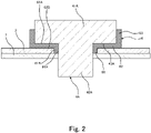
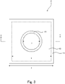
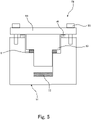
- the power storage assembly of the present disclosure preferably has an exterior can, an electric element housed in the exterior can, a lid to close an opening of the exterior can, and an external terminal installed on the lid, and the gasket is held between the lid and the external terminal.
- a gasket containing a copolymer containing a tetrafluoroethylene unit and a fluoro(alkyl vinyl ether) unit, wherein the copolymer has a content of the fluoro(alkyl vinyl ether) unit of 2.0 to 4.4% by mass with respect to the whole of the monomer units, a melt flow rate of 0.5 to 50 g/10 min, and the number of functional groups of 50 or less per 10 6 main-chain carbon atoms.
- the content of the fluoro(alkyl vinyl ether) unit is preferably 4.2% by mass or lower with respect to the whole of the monomer units.
- the melt flow rate is preferably 45 g/10 min or lower.
- the present disclosure enables to provide a power storage assembly which is high in sealing property which does not deteriorate even in the case where the temperature becomes abnormally high.
- the present disclosure further enables to provide a gasket which can remarkably enhance the sealing property of a power storage assembly, which does not deteriorate even in the case where the temperature becomes abnormally high.
- a power storage assembly of the present disclosure has a gasket containing a copolymer containing a tetrafluoroethylene (TFE) unit and a fluoro(alkyl vinyl ether) (FAVE) unit.
- TFE tetrafluoroethylene
- FAVE fluoro(alkyl vinyl ether)
- Patent Document 1 describes that a vehicular secondary battery is sometimes exposed to a high temperature of 85°C or higher in the use environment, and in order to keep the airtightness and the liquid tightness of the battery interior, it is important that a sealing material exhibits a sufficient compression recovering property even under such a severe use condition, and can maintain high adhesion between an exterior can and a sealing body.
- the life of power storage assembly is lengthened recently, in the case where the electrolytic solution is diffused outside the power storage assembly, the amount of the electrolytic solution in the power storage assembly may gradually decrease and this may adversely affect also the power storage performance, by using the power storage assembly for a long period.
- sealing a power storage assembly by using a gasket containing a copolymer in which the content of the FAVE unit, the melt flow rate (MFR) and the number of functional groups are suitably controlled, can prevent not only the leakage of an electrolytic solution from the power storage assembly, but also the permeation through the gasket of the electrolytic solution and the diffusion thereof to the outside. Additionally, it has also been found that the gasket containing such a copolymer exhibits excellent sealability even at high temperatures, and therefore, even in the case where the power storage assembly abnormally generates heat and the temperature becomes high, the leakage and the diffusion of the electrolytic solution to the outside can be also prevented.
- the power storage assembly of the present disclosure has been completed based on these findings, and exhibits high sealing property which does not deteriorate even in the case where the temperature becomes abnormally high.
- the copolymer contained in the gasket equipped in the power storage assembly of the present disclosure is a melt-fabricable fluororesin.
- the melt-fabricability means that a polymer can be melted and processed by using conventional processing devices such as an extruder or an injection molding machine.
- the copolymer contained in the gasket equipped in the power storage assembly of the present disclosure contains the TFE unit and the FAVE unit.
- the FAVE is preferably a monomer represented by the general formula (1), more preferably at least one selected from the group consisting of perfluoro(methyl vinyl ether), perfluoro(ethyl vinyl ether) (PEVE), and perfluoro(propyl vinyl ether) (PPVE), still more preferably at least one selected from the group consisting of PEVE and PPVE, and especially preferably PPVE.
- the content of the fluoroalkyl vinyl ether (FAVE) unit of the copolymer is 2.0 to 6.0% by mass with respect to the whole of the monomer units.
- the content of the FAVE unit of the copolymer is preferably 5.5% by mass or lower, more preferably 5.0% by mass or lower and still more preferably 4.7% by mass or lower.
- the copolymer satisfying the above range regarding the FAVE unit content provides a gasket which enables to suppress further more permeation of the electrolytic solution and has further improved sealability at high temperatures; therefore, the power storage assembly having further high sealing property which can be much less deteriorated even in the case where the temperature becomes abnormally high, can be provided.
- the content of the FAVE unit of the copolymer is, from the viewpoint of suppressing the permeation of the electrolytic solution in a very high level, and improving the sealability at high temperatures to a very high level, preferably 2.2% by mass or higher, more preferably 2.4% by mass or higher and still more preferably 2.6% by mass or higher, and preferably 4.4% by mass or lower.
- the content of the FAVE unit of the copolymer is, from the viewpoint of suppressing the permeation of the electrolytic solution in a much higher level, and improving the sealability at high temperatures to a much higher level, preferably 4.2% by mass or lower, more preferably 3.8% by mass or lower, still more preferably 3.5% by mass or lower and especially preferably 3.2% by mass or lower.
- the content of the tetrafluoroethylene (TFE) unit of the copolymer is 98.0 to 94.0% by mass with respect to the whole of the monomer units.
- the content of the TFE unit of the copolymer is preferably 94.5% by mass or higher, more preferably 95.0% by mass or higher and still more preferably 95.3% by mass or higher.
- the copolymer satisfying the above range regarding the TFE unit content provides a gasket which enables to suppress further more permeation of the electrolytic solution and has further improved sealability at high temperatures; therefore, the power storage assembly having further high sealing property which can be much less deteriorated even in the case where the temperature becomes abnormally high, can be provided.
- the content of the TFE unit of the copolymer is, from the viewpoint of suppressing the permeation of the electrolytic solution in a very high level, and improving the sealability at high temperatures to a very high level, preferably 97.8% by mass or lower, more preferably 97.6% by mass or lower and still more preferably 97.4% by mass or lower, and preferably 95.6% by mass or higher.
- the content of the TFE unit of the copolymer is, from the viewpoint of suppressing the permeation of the electrolytic solution in a much higher level, and improving the sealability at high temperatures to a much higher level, preferably 95.8% by mass or higher, more preferably 96.2% by mass or higher, still more preferably 96.5% by mass or higher and especially preferably 96.8% by mass or higher.
- the content of each monomer unit in the copolymer can be measured by a 19 F-NMR method.
- the copolymer may also contain monomer units derived from monomers copolymerizable with TFE and FAVE.
- the content of the monomer units copolymerizable with TFE and FAVE is, with respect to the whole of the monomer units of the copolymer, preferably 0 to 4.00% by mol, more preferably 0.05 to 1.40% by mol and still more preferably 0.10 to 0.50% by mol.
- HFP hexafluoropropylene
- the copolymer is preferably at least one selected from the group consisting of a copolymer consisting only of the TFE unit and the FAVE unit, and TFE/HFP/FAVE copolymer, and is more preferably a copolymer consisting only of the TFE unit and the FAVE unit.
- the melt flow rate (MFR) of the copolymer is 0.5 to 55 g/10 min.
- the MFR of the copolymer is preferably 1.0 g/10 min or higher and more preferably 5.0 g/10 min or higher.
- the copolymer satisfying the above MFR range provides a gasket which enables to suppress further more permeation of the electrolytic solution and has further improved sealability at high temperatures; therefore, the power storage assembly having further high sealing property which can be much less deteriorated even in the case where the temperature becomes abnormally high, can be provided.
- the MFR of the copolymer is, from the viewpoint of suppressing the permeation of the electrolytic solution in a very high level, and improving the sealability at high temperatures to a very high level, preferably 50 g/10 min or lower.
- the MFR of the copolymer is, from the viewpoint of suppressing the permeation of the electrolytic solution in a much higher level, and improving the sealability at high temperatures to a much higher level, preferably 45 g/10 min or lower, more preferably 40 g/10 min or lower, still more preferably 35 g/10 min or lower and especially preferably 30 g/10 min or lower.
- the MFR of the copolymer is, in the case where the sealability at a very high temperature (for example, 150°C) is especially required, preferably 20 g/10 min or lower, more preferably 15 g/10 min or lower, still more preferably 10 g/10 min or lower and especially preferably 5.0 g/10 min or lower.
- a very high temperature for example, 150°C
- the MFR of the copolymer is, in the case where there is attached much importance to the balance between the low permeation and the sealability of the electrolytic solution and the easiness of production of the gasket, may be 10 g/10 min or higher, or may be 20 g/10 min or higher.
- the melt flow rate of the copolymer is a value obtained as a mass (g/10 min) of the polymer flowing out from a nozzle of 2.1 mm in inner diameter and 8 mm in length per 10 min at 372°C under a load of 5 kg using a melt indexer, according to ASTM D1238.
- the number of functional groups per 10 6 main-chain carbon atoms of the copolymer is 50 or less.
- the number of functional groups is preferably 40 or less, more preferably 30 or less, still more preferably 20 or less and especially preferably 15 or less.
- the copolymer satisfying the above range regarding the number of functional groups provides a gasket which enables to suppress further more permeation of the electrolytic solution and has further improved sealability at high temperatures; therefore, the power storage assembly having further high sealing property which can be much less deteriorated even in the case where the temperature becomes abnormally high, can be provided. Further, corrosion of a metal mold used for injection molding can more be suppressed and dissolving out of fluorine ions into the electrolytic solution can more be suppressed.
- infrared spectroscopy For identification of the kind of the functional groups and measurement of the number of the functional groups, infrared spectroscopy can be used.
- the number of the functional groups is measured, specifically, by the following method.
- the copolymer is molded by cold press to prepare a film of 0.25 to 0.3 mm in thickness.
- the film is analyzed by Fourier transform infrared spectroscopy to obtain an infrared absorption spectrum, and a difference spectrum against a base spectrum that is completely fluorinated and has no functional groups is obtained. From an absorption peak of a specific functional group observed on this difference spectrum, the number N of the functional group per 1 ⁇ 10 6 carbon atoms in the copolymer is calculated according to the following formula (A).
- N I ⁇ K / t
- the absorption frequency, the molar absorption coefficient and the correction factor are shown in Table 1. Then, the molar absorption coefficients are those determined from FT-IR measurement data of low molecular model compounds.
- Absorption frequencies of -CH 2 CF 2 H, -CH 2 COF, - CH 2 COOH, -CH 2 COOCH 3 and -CH 2 CONH 2 are lower by a few tens of kaysers (cm -1 ) than those of -CF 2 H, -COF, -COOH free and -COOH bonded, -COOCH 3 and -CONH 2 shown in the Table, respectively.
- the number of the functional group - COF is the total of the number of a functional group determined from an absorption peak having an absorption frequency of 1,883 cm -1 derived from -CF 2 COF and the number of a functional group determined from an absorption peak having an absorption frequency of 1,840 cm -1 derived from -CH 2 COF.
- the functional groups are ones present on main chain terminals or side chain terminals of the copolymer, and ones present in the main chain or the side chains.
- the functional groups are introduced to the copolymer by, for example, a chain transfer agent or a polymerization initiator used for production of the copolymer.
- a chain transfer agent for example, a chain transfer agent, or a peroxide having a structure of -CH 2 OH as the polymerization initiator
- - CH 2 OH is introduced on the main chain terminals of the copolymer.
- the functional group is introduced on the side chain terminal of the copolymer by polymerizing a monomer having the functional group.
- the copolymer satisfying the above range regarding the number of functional groups can be obtained by subjecting the copolymer to a fluorination treatment. That is, the copolymer is preferably one which is subjected to the fluorination treatment. Further, the copolymer preferably has -CF 3 terminal groups.
- the gasket can contain a copolymer containing the TFE unit and the FAVE unit wherein the copolymer has a content of the FAVE unit of 2.0 to 4.4% by mass with respect to the whole of the monomer units, a melt flow rate of 0.5 to 50 g/10 min, and the number of functional groups of 50 or less per 10 6 main-chain carbon atoms.
- the gasket enables to suppress the permeation of an electrolytic solution in a very high level, and a power storage assembly can be sealed in a very high level even in a high-temperature environment. Therefore, the power storage assembly having very high sealing property which can be much less deteriorated even in the case where the temperature becomes abnormally high, can be provided.
- the gasket can contain a copolymer having a content of the FAVE unit of 2.0 to 4.2% by mass with respect to the whole of the monomer units, a melt flow rate of 0.5 to 45 g/10 min, and the number of functional groups of 50 or less per 10 6 main-chain carbon atoms.
- the gasket enables to suppress permeation of the electrolytic solution at a further high level and to seal a power storage assembly in a further high level even under high temperatures. Therefore, a power storage assembly having further high sealing property which can be hardly deteriorated even in the case where the temperature becomes abnormally high, can be provided.
- the low permeation of the electrolytic solution through the gasket can be evaluated, for example, based on the amount of fluorine ions dissolving out in an electrolytic solution permeation test described later.
- the sealability at high temperatures of the gasket can be evaluated, for example, based on the surface pressure at 150°C of the gasket.
- the content of the FAVE unit of the copolymer which the gasket contains is, from the viewpoint of suppressing the permeation of the electrolytic solution in a much higher level, and improving the sealability at high temperatures to a much higher level, preferably 4.2% by mass or lower, more preferably 3.8% by mass or lower, still more preferably 3.5% by mass or lower and especially preferably 3.2% by mass or lower.
- the content of the TFE unit of the copolymer which the gasket contains is, from the viewpoint of suppressing the permeation of the electrolytic solution in a much higher level, and improving the sealability at high temperatures to a much higher level, preferably 95.8% by mass or higher, more preferably 96.2% by mass or higher, still more preferably 96.5% by mass or higher and especially preferably 96.8% by mass or higher.
- the MFR of the copolymer which the gasket contains is, from the viewpoint of suppressing the permeation of the electrolytic solution in a much higher level, and improving the sealability at high temperatures to a much higher level, preferably 45 g/10 min or lower, more preferably 40 g/10 min or lower, still more preferably 35 g/10 min and especially preferably 30 g/10 min or lower.
- the MFR of the copolymer which the gasket contains is, in the case where the sealability at a very high temperature (for example, 150°C) is especially required, preferably 20 g/10 min or lower, more preferably 15 g/10 min or lower, still more preferably 10 g/10 min or lower and especially preferably 5.0 g/10 min or lower.
- a very high temperature for example, 150°C
- the melting point of the copolymer is preferably 298 to 315°C and more preferably 302 to 310°C.
- the copolymer satisfying the above range regarding the melting point provides a gasket which enables to suppress further more permeation of the electrolytic solution and has further improved sealability at high temperatures; therefore, the power storage assembly having further high sealing property which can be much less deteriorated even in the case where the temperature becomes abnormally high, can be provided.
- the melting point can be measured by using a differential scanning calorimeter [DSC].
- the amount of fluorine ions dissolving out therefrom and detected in an electrolytic solution immersion test is, in terms of mass, preferably 1.0 ppm or less, more preferably 0.9 ppm or less and still more preferably 0.8 ppm or less.
- the copolymer satisfying the above range regarding the amount of fluorine ions dissolving out enables to further suppress generation of gasses such as HF in the electrolytic solution, the deterioration of the performance, and the shortening of the service life of the power storage assembly.
- the electrolytic solution immersion test can be carried out by preparing a molded test piece of the copolymer having a weight corresponding to that of 10 sheets of molded articles (15 mm ⁇ 15 mm ⁇ 0.2 mm) of the copolymer, and putting, in a thermostatic chamber of 80°C, a glass-made sample bottle in which the test piece and 2 g of dimethyl carbonate (DMC) and allowing the resultant to stand for 144 hours.
- DMC dimethyl carbonate
- the amount of the electrolytic solution permeation of the copolymer may be 0.0055 g/1,000 h or smaller, and is preferably 0.0050 g/1,000 h or smaller, more preferably 0.0047 g/1,000 h or smaller, still more preferably 0.0045 g/1,000 h or smaller and especially preferably 0.0042 g/1,000 h or smaller; and the lower limit is not limited, but may be 0.0020 g/1,000 h or larger.
- the copolymer satisfying the above range regarding the amount of the electrolytic solution permeation of the copolymer enables to provide the power storage assembly having much higher sealing property which can be much less deteriorated even in the case where the temperature becomes abnormally high.
- the amount of the electrolytic solution permeating the copolymer can be reduced by controlling the content of the FAVE unit, the melt flow rate (MFR) and the number of functional groups of the copolymer.
- the amount of an electrolytic solution permeation of the copolymer can be identified by measuring the mass of an electrolytic solution (EC/DEC (30/70% by volume) permeating the gasket (outer diameter: ⁇ 17.7 mm, inner diameter: ⁇ 14.3 mm, thickness: 1.6 mmt) under the condition of 60°C and 1,000 hours, where the gasket used is obtained by injection molding the copolymer.
- EC/DEC electrolytic solution
- the storage elastic modulus (E') at 150°C of the copolymer is preferably 10 MPa or higher and more preferably 50 MPa or higher, and preferably 1,000 MPa or lower, more preferably 500 MPa or lower and still more preferably 200 MPa or lower.
- the copolymer satisfying the above range regarding the storage elastic modulus (E') at 150°C enables to provide the power storage assembly having a sealing property which can be much less deteriorated even in the case where the temperature becomes abnormally high.
- the storage elastic modulus (E') can be measured by carrying out a dynamic viscoelasticity measurement under the condition of a temperature-increasing rate of 2°C/min and a frequency of 10 Hz and in the range of 30 to 250°C.
- the surface pressure at 150°C of the copolymer is preferably 0.3 MPa or higher, more preferably 0.5 MPa or higher and still more preferably 0.8 MPa or higher; the upper limit is not limited, but may be 2.0 MPa or lower.
- the gasket containing the copolymer having high surface pressure at 150°C can exhibit excellent sealability at high temperatures. Therefore, use of a gasket containing such a copolymer enables to provide the power storage assembly having a sealing property which can be much less deteriorated even in the case where the temperature becomes abnormally high.
- the surface pressure at 150°C of the copolymer can be raised by controlling the content of the FAVE unit, the melt flow rate (MFR) and the number of functional groups of the copolymer.
- the surface pressure can be determined as follows. A test piece is deformed at a compression deformation rate of 50%, allowed to stand as is at 150°C for 18 hours, released from the compressive state and allowed to stand at room temperature for 30 min, and thereafter, the height of the test piece (height of the test piece after being compressively deformed) is measured; and the surface pressure can be calculated by the following formula using the height of the test piece after being compressively deformed, and the storage elastic modulus (MPa) at 150°C.
- the copolymer for forming the gasket equipped in the power storage assembly of the present disclosure can be produced by a polymerization method such as suspension polymerization, solution polymerization, emulsion polymerization or bulk polymerization.
- the polymerization method is preferably emulsion polymerization or suspension polymerization.
- conditions such as temperature and pressure, and a polymerization initiator and other additives can suitably be set depending on the formulation and the amount of the copolymer.
- an oil-soluble radical polymerization initiator or a water-soluble radical polymerization initiator may be used.
- the oil-soluble radical polymerization initiator may be a known oil-soluble peroxide, and examples thereof typically include:
- the di[fluoro(or fluorochloro)acyl] peroxides include diacyl peroxides represented by [(RfCOO)-] 2 wherein Rf is a perfluoroalkyl group, an ⁇ -hydroperfluoroalkyl group or a fluorochloroalkyl group.
- di[fluoro(or fluorochloro)acyl] peroxides examples include di( ⁇ -hydro-dodecafluorohexanoyl) peroxide, di( ⁇ -hydro-tetradecafluoroheptanoyl) peroxide, di( ⁇ -hydro-hexadecafluorononanoyl) peroxide, di(perfluoropropionyl) peroxide, di(perfluorobutyryl) peroxide, di(perfluorovaleryl) peroxide, di(perfluorohexanoyl) peroxide, di(perfluoroheptanoyl) peroxide, di(perfluorooctanoyl) peroxide, di(perfluorononanoyl) peroxide, di( ⁇ -chloro-hexafluorobutyryl) peroxide, di( ⁇ -chloro-decafluorohexanoyl) peroxide,
- the water-soluble radical polymerization initiator may be a known water-soluble peroxide, and examples thereof include ammonium salts, potassium salts and sodium salts of persulfuric acid, perboric acid, perchloric acid, perphosphoric acid, percarbonic acid and the like, organic peroxides such as disuccinoyl peroxide and diglutaroyl peroxide, and t-butyl permaleate and t-butyl hydroperoxide.
- a reductant such as a sulfite or a sulfite salt may be combined with a peroxide and used, and the amount thereof to be used may be 0.1 to 20 times with respect to the peroxide.
- a surfactant In the polymerization, a surfactant, a chain transfer agent and a solvent may be used, which are conventionally known.
- the surfactant may be a known surfactant, for example, nonionic surfactants, anionic surfactants and cationic surfactants may be used.
- fluorine-containing anionic surfactants are preferred, and more preferred are linear or branched fluorine-containing anionic surfactants having 4 to 20 carbon atoms, which may contain an ether bond oxygen (that is, an oxygen atom may be inserted between carbon atoms).
- the amount of the surfactant to be added is preferably 50 to 5,000 ppm.
- chain transfer agent examples include hydrocarbons such as ethane, isopentane, n-hexane and cyclohexane; aromatics such as toluene and xylene; ketones such as acetone; acetate esters such as ethyl acetate and butyl acetate; alcohols such as methanol and ethanol; mercaptans such as methylmercaptan; and halogenated hydrocarbons such as carbon tetrachloride, chloroform, methylene chloride and methyl chloride.
- the amount of the chain transfer agent to be added may vary depending on the chain transfer constant value of the compound to be used, but is usually in the range of 0.01 to 20% by mass with respect to the solvent in the polymerization.
- the solvent may include water and mixed solvents of water and an alcohol.
- a fluorosolvent may be used.
- the fluorosolvent may include hydrochlorofluoroalkanes such as CH 3 CClF 2 , CH 3 CCl 2 F, CF 3 CF 2 CCl 2 H and CF 2 ClCF 2 CFHCl; chlorofluoroalaknes such as CF 2 ClCFClCF 2 CF 3 and CF 3 CFClCFClCF 3 ; hydrofluroalkanes such as CF 3 CFHCFHCF 2 CF 2 CF 3 , CF 2 HCF 2 CF 2 CF 2 CF 2 H and CF 3 CF 2 CF 2 CF 2 CF 2 CF 2 CF 2 H; hydrofluoroethers such as CH 3 OC 2 F 5 , CH 3 OC 3 F 5 CF 3 CF 2 CH 2 OCHF 2 , CF 3 CHFCF 2 OCH 3 , CHF 2 CF 2 OCH 2 F, (CF 3 ) 2
- the polymerization temperature is not limited, and may be 0 to 100°C.
- the polymerization pressure is suitably set depending on other polymerization conditions to be used such as the kind, the amount and the vapor pressure of the solvent, and the polymerization temperature, but may usually be 0 to 9.8 MPaG.
- the copolymer in the case of obtaining an aqueous dispersion containing the copolymer by the polymerization reaction, the copolymer can be recovered by coagulating, cleaning and drying the copolymer contained in the aqueous dispersion. Then in the case of obtaining the copolymer as a slurry by the polymerization reaction, the copolymer can be recovered by taking out the slurry from a reaction container, and cleaning and drying the slurry. The copolymer can be recovered in a shape of powder by the drying.
- the copolymer obtained by the polymerization may be molded into pellets.
- a method of molding into pellets is not limited, and a conventionally known method can be used. Examples thereof include methods of melt extruding the copolymer by using a single-screw extruder, a twinscrew extruder or a tandem extruder and cutting the resultant into a predetermined length to mold the copolymer into pellets.
- the extrusion temperature in the melt extrusion needs to be varied depending on the melt viscosity and the production method of the copolymer, and is preferably the melting point of the copolymer + 20°C to the melting point of the copolymer + 140°C.
- a method of cutting the copolymer is not limited, and there can be adopted a conventionally known method such as a strand cut method, a hot cut method, an underwater cut method, or a sheet cut method.
- Volatile components in the obtained pellets may be removed by heating the pellets (degassing treatment).
- the obtained pellets may be treated by bringing the pellets into contact with hot water of 30 to 200°C, steam of 100 to 200°C or hot air of 40 to 200°C.
- the copolymer obtained by the polymerization may be subjected to fluorination treatment.
- the fluorination treatment can be carried out by bringing the copolymer having been subjected to no fluorination treatment into contact with a fluorine-containing compound.
- thermally relatively stable functional groups thereof, such as -CF 2 H can be converted to thermally very stable -CF 3 .
- the fluorine-containing compound is not limited, but includes fluorine radical sources generating fluorine radicals under the fluorination treatment condition.
- the fluorine radical sources include F 2 gas, CoF 3 , AgF 2 , UF 6 , OF 2 , N 2 F 2 , CF 3 OF, halogen fluorides (for example, IF 5 and CIF 3 ).
- the fluorine radical source such as F 2 gas may be, for example, one having a concentration of 100%, but from the viewpoint of safety, the fluorine radical source is preferably mixed with an inert gas and diluted therewith to 5 to 50% by mass, and then used; and it is more preferably to be diluted to 15 to 30% by mass.
- the inert gas includes nitrogen gas, helium gas and argon gas, but from the viewpoint of the economic efficiency, nitrogen gas is preferred.
- the condition of the fluorination treatment is not limited, and the copolymer in a melted state may be brought into contact with the fluorine-containing compound, but the fluorination treatment can be carried out usually at a temperature of not higher than the melting point of the copolymer, preferably at 20 to 240°C and more preferably at 100 to 220°C.
- the fluorination treatment is carried out usually for 1 to 30 hours and preferably 5 to 25 hours.
- the fluorination treatment is preferred which brings the copolymer having been subjected to no fluorination treatment into contact with fluorine gas (F 2 gas) .
- the gasket may contain other components.
- the other components may include fillers, plasticizers, pigments, colorants, antioxidants, ultraviolet absorbents, flame retarders, antiaging agents, antistatic agents and antibacterial agents.
- fillers are preferred.
- the fillers include silica, kaolin, clay, organo clay, talc, mica, alumina, calcium carbonate, calcium terephthalate, titanium oxide, calcium phosphate, calcium fluoride, lithium fluoride, crosslinked polystyrene, potassium titanate, carbon, boron nitride, carbon nanotube and glass fiber.
- the gasket can contain other components other than the copolymer.
- the gasket preferably contains less amounts of the other components, and most preferably contains no other components.
- the amount of the other components is, with respect to the mass of the gasket, preferably 30% by mass or lower, more preferably 10% by mass or lower and most preferably 0% by mass, that is, it is most preferable that the gasket contains no other components.
- the gasket may be one consisting only of the copolymer.
- the gasket can be produced by molding the copolymer or a composition containing the copolymer and the other components into a desired shape and size.
- a method of producing the composition includes a method of dry mixing the copolymer and the other components, and a method of previously mixing the copolymer and the other components by a mixer and then melt kneading the mixture by a kneader, melt extruder or the like.
- a method of molding the copolymer or the composition is not limited, and includes injection molding, extrusion, compression molding, blow molding and transfer molding.
- preferred are compression molding, injection molding or transfer molding; and injection molding or transfer molding are more preferred because the gasket can be produced in a high productivity. That is, the gasket is preferably an injection molded article or a transfer molded article, because the gasket can be produced in a high productivity.
- a power storage assembly illustrated in Figure 1 is a closed rectangular secondary battery.
- the power storage assembly 10 has an exterior can 1 and a lid 2.
- the exterior can 1 has an opening (not shown in figure) formed on the upper part facing the bottom face 3.
- an electric element such as a power generator is housed, and the opening of the exterior can is hermetically sealed with the lid 2.
- the peripheral portion of the lid 2 is joined to the edge portion of the opening of the exterior can 1.
- the lid 2 is provided with a liquid injection hole for injecting an electrolytic solution in the exterior can 1.
- the electrolytic solution may be one or two or more known solvents such as propylene carbonate, ethylene carbonate, butylene carbonate, ⁇ -butyrolactone, 1,2-dimethoxyethane, 1,2-diethoxyethane, dimethyl carbonate, diethyl carbonate and ethyl methyl carbonate. Solutions can also be used in which an electrolyte is dissolved in an electrolytic solution.
- the electrolyte is not limited, but may be LiClO 4 , LiAsF 6 , LiPF 6 , LiBF 4 , LiCl, LiBr, CH 3 SO 3 Li, CF 3 SO 3 Li, cesium carbonate and the like.
- the liquid injection hole is installed with a plug 5, and the plug 5 is jointed to the edge portion of the liquid injection hole of the lid 2.
- the joining can be carried out by welding using laser.
- the lid 2 is installed with a first external terminal 4A and a second external terminal 4B; and an externally generated electric power is supplied through the first external terminal 4A and the second external terminal 4B to the electric element, and is stored in the power storage assembly; and then, the power is supplied to an external load.
- the first external terminal 4A is a positive electrode terminal; and the second external terminal 4B is a negative electrode terminal.
- the first external terminal 4A is constituted, for example, of aluminum or an aluminum alloy.
- the second external terminal 4B is constituted, for example, of copper or a copper alloy.
- FIG. 2 is a schematic cross-sectional view illustrating a constitution of a terminal part of a power storage assembly. Places are usually different where the first external terminal and the second external terminal are arranged on a constituting material or the lid 2, but since the other constitutions can be made identical, the following description will be made by way of an example of the first external terminal 4A.
- the first external terminal 4A has a terminal head part 41A having a rectangular parallelepiped block shape and a cylindrical shaft part 42A.
- the terminal head part 41A has an external profile of a rectangular lower face 43A; and the shaft part 42A protrudes from the lower face 43A of the terminal head part 41A.
- the gasket 6 has a cylindrical part 61, a flange part 62 extending from one opening of the cylindrical part 61 in the radial direction, and a side wall part 63 rising from the periphery of the flange part 62.
- the cylindrical part 61 is externally fitted on the shaft part 42A of the first external terminal 4A, and the contacting face 61A of the inner peripheral portion of the cylindrical part 61 makes contact with an outer peripheral face of the shaft part 42A. Then, the cylindrical part 61 is inserted in a through-hole of the lid 2, and the contacting face 61B of the outer peripheral portion of the cylindrical part 61 makes contact with the inner peripheral face of the through-hole of the lid 2.
- the flange part 62 is held between the lid 2 and the first external terminal 4A, and the contacting face 62A of the flange part 62 makes contact with the lower face 43A of the first external terminal 4A. Further, the contacting face 62B of the flange part 62 makes contact with a front side of the lid 2.
- the gasket 6 makes contact with the first external terminal 4A and the lid 2 in the state that the cylindrical part 61 and the flange part 62 of the gasket 6 are compressed, and the sealing property of the power storage assembly can thereby be secured.
- the sealing property of the power storage assembly can be further enhanced.
- the thickness of the gasket is preferably 0.5 to 2.5 mm, more preferably 2.0 mm or smaller, still more preferably 1.5 mm or smaller and especially preferably 1.0 mm or smaller.
- a gasket having a smaller thickness can suppress further more permeation of the electrolytic solution, however, in the case where the thickness of the gasket is too small, sufficient rebound resilience and sufficient sealing property (for example, liquid leakage resistance) cannot be provided.
- the permeation of the electrolytic solution can be further more suppressed while further enhancing the sealing property of the power storage assembly.
- Figure 3 is a front view of the gasket 6; and Figure 4 is a cross-sectional view taken on line A-A' of the gasket 6.
- the thickness of the gasket refers to the thickness of parts contributing to the sealing property of the power storage assembly, and is, in the gasket 6 illustrated in Figure 4 , thickness d and thickness e.
- the thickness d and the thickness e may be different from each other as in the gasket illustrated in Figure 4 , or may be identical. In either the case of the thickness d and the thickness e being identical or the case of being different, it is preferable that the thicknesses of the both are suitably controlled.
- the thicknesses of parts of the whole gasket may be controlled in the above range.
- the thickness d and the thickness e, but also the thickness f is suitably controlled to fall in the above range.
- the sealing area of the gasket is preferably 0.5 to 50 cm 2 , and the upper limit thereof is more preferably 35 cm 2 , the upper limit thereof is still more preferably 20 cm 2 and the upper limit thereof is especially preferably 10 cm 2 ; and the lower limit thereof is more preferably 1 cm 2 and the lower limit thereof is still more preferably 2 cm 2 .
- a smaller sealing area of the gasket gives a larger distance between the inside and the outside of the power storage assembly, and the permeation of the electrolytic solution can much more be suppressed, but since downsizing of the power storage assembly is demanded, the sealing area needs to be made small; however, it is difficult for conventional gaskets to reduce the sealing area and simultaneously sufficiently suppress the permeation of the electrolytic solution.
- the gasket of the present disclosure enables to suppress the permeation of the electrolytic solution further more while achieving the downsizing of the power storage assembly by reducing the sealing area of the gasket as mentioned above, since the copolymer is suitably controlled in terms of the content of the FAVE unit, the melt flow rate (MFR) and the number of functional groups.
- the sealing area of the gasket is an area of portions contributing to the sealing property of the power storage assembly, and is, in the gasket 6 illustrated in Figure 2 , a total area of the contacting faces 61A, 61B, 62A and 62B.
- the sealing property of the power storage assembly can be further enhanced.
- the compression deformation rate of the gasket is preferably 20 to 60%.
- the compression deformation rate of the gasket can be calculated by the following formula.
- Compression deformation rate (%) [(a thickness of the gasket before being compressed) - (a thickness of the gasket in the compressed state)]/(the thickness of the gasket before being compressed) ⁇ 100
- a gasket illustrated in Figure 3 and Figure 4 has the following size.
- the power storage assembly may be, for example, a primary battery or may be, for example, a power storage battery (secondary battery) or a power storage element.
- the power storage assembly may also be a nonaqueous electrolyte battery.
- the nonaqueous electrolyte battery includes every battery having an electrolytic solution and an electric power generating element. Examples of the nonaqueous electrolyte battery include lithium ion primary batteries, lithium ion secondary batteries, nickel hydrogen batteries, lithium ion capacitors and electric double layer capacitors.
- the content of each monomer unit was measured by an NMR analyzer (for example, manufactured by Bruker BioSpin GmbH, AVANCE 300, high-temperature probe).
- MFR Melt flow rate
- the polymer was made to flow out from a nozzle of 2.1 mm in inner diameter and 8 mm in length at 372°C under a load of 5 kg by using a Melt Indexer G-01 (manufactured by Toyo Seiki Seisaku-sho, Ltd.) according to ASTM D1238, and the mass (g/10 min) of the polymer flowing out per 10 min was determined.
- a Melt Indexer G-01 manufactured by Toyo Seiki Seisaku-sho, Ltd.
- Pellets of the copolymer was molded by cold press into a film of 0.25 to 0.3 mm in thickness.
- the film was 40 times scanned and analyzed by a Fourier transform infrared spectrometer [FT-IR (Spectrum One, manufactured by PerkinElmer, Inc.)] to obtain an infrared absorption spectrum, and a difference spectrum against a base spectrum that is completely fluorinated and has no functional groups is obtained. From an absorption peak of a specific functional group observed on this difference spectrum, the number N of the functional group per 1 ⁇ 10 6 carbon atoms in the sample was calculated according to the following formula (A).
- N I ⁇ K / t
- the absorption frequency, the molar absorption coefficient and the correction factor are shown in Table 2.
- the molar absorption coefficients are those determined from FT-IR measurement data of low molecular model compounds.
- the polymer was heated, as a first temperature raising step at a temperature-increasing rate of 10°C/min from 200°C to 350°C, then cooled at a cooling rate of 10°C/min from 350°C to 200°C, and then again heated, as second temperature raising step, at a temperature-increasing rate of 10°C/min from 200°C to 350°C by using a differential scanning calorimeter (trade name: X-DSC7000, manufactured by Hitachi High-Tech Science Corp.); and the melting point was determined from a melting curve peak observed in the second temperature raising step.
- a differential scanning calorimeter trade name: X-DSC7000, manufactured by Hitachi High-Tech Science Corp.
- TFE Since the pressure in the system decreased along with the progress of the polymerization, TFE was continuously supplied to make the pressure constant, and 0.058 kg of PPVE was added for every 1 kg of TFE supplied and the polymerization was continued for 19 hours. TFE was released to return the pressure in the autoclave to the atmospheric pressure, and thereafter, an obtained reaction product was washed with water and dried to thereby obtain 30 kg of a powder.
- the obtained powder was melt extruded at 360°C by a screw extruder (trade name: PCM46, manufactured by Ikegai Corp.) to thereby obtain pellets of a TFE/PPVE copolymer.
- the PPVE content of the obtained pellets was measured by the method described above. The result is shown in Table 3.
- the obtained pellets were put in a vacuum vibration-type reactor VVD-30 (manufactured by Okawara MFG. Co., Ltd.), and heated to 210°C.
- F 2 gas diluted to 20% by volume with N 2 gas was introduced to the atmospheric pressure.
- vacuumizing was once carried out and F 2 gas was again introduced.
- F 2 gas was again introduced.
- vacuumizing was again carried out and F 2 gas was again introduced.
- the reaction was carried out at a temperature of 210°C for 10 hours.
- the reactor interior was replaced sufficiently by N 2 gas to finish the fluorination reaction.
- TFE Since the pressure in the system decreased along with the progress of the polymerization, TFE was continuously supplied to make the pressure constant, and 0.040 kg of PPVE was added for every 1 kg of TFE supplied and the polymerization was continued for 20 hours. TFE was released to return the pressure in the autoclave to the atmospheric pressure, and thereafter, an obtained reaction product was washed with water and dried to thereby obtain 30 kg of a powder.
- the obtained powder was melt extruded at 360°C by a screw extruder (trade name: PCM46, manufactured by Ikegai Corp.) to thereby obtain pellets of a TFE/PPVE copolymer.
- the PPVE content of the obtained pellets was measured by the method described above. The result is shown in Table 3.
- the obtained pellets were put in a vacuum vibration-type reactor VVD-30 (manufactured by Okawara MFG. Co., Ltd.), and heated to 160°C.
- F 2 gas diluted to 20% by volume with N 2 gas was introduced to the atmospheric pressure.
- vacuumizing was once carried out and F 2 gas was again introduced.
- F 2 gas was again introduced.
- vacuumizing was again carried out and F 2 gas was again introduced.
- the reaction was carried out at a temperature of 160°C for 5 hours.
- the reactor interior was replaced sufficiently by N 2 gas to finish the fluorination reaction.
- Fluorinated pellets were obtained as in Experimental Example 2, except for changing the charged amount of pure water to 27.0 L, PPVE to 1.20 kg and methanol to 3.00 kg, introducing TFE under pressure to 0.57 MPa, changing the charged amount of the 50% methanol solution of di-n-propyl peroxydicarbonate to 0.014 kg, adding 0.040 kg of PPVE for every 1 kg of TFE supplied, and changing the polymerization time to 21 hours to obtain 30 kg of a powder.
- Table 3 The results are shown in Table 3.
- Fluorinated pellets were obtained as in Experimental Example 1, except for changing the charged amount of pure water to 26.6 L, perfluorocyclobutane to 30.4 kg, PPVE to 0.77 kg and methanol to 2.40 kg, introducing TFE under pressure to 0.58 MPa, changing the charged amount of the 50% methanol solution of di-n-propyl peroxydicarbonate to 0.011 kg, adding 0.031 kg of PPVE for every 1 kg of TFE supplied, and changing the polymerization time to 9 hours to obtain 15 kg of a powder.
- Table 3 The results are shown in Table 3.
- Fluorinated pellets were obtained as in Experimental Example 1, except for changing the charged amount of pure water to 26.6 L, perfluorocyclobutane to 30.4 kg, PPVE to 0.77 kg and methanol to 3.30 kg, introducing TFE under pressure to 0.58 MPa, changing the charged amount of the 50% methanol solution of di-n-propyl peroxydicarbonate to 0.011 kg, adding 0.031 kg of PPVE for every 1 kg of TFE supplied, and changing the polymerization time to 10 hours to obtain 15 kg of a powder.
- Table 3 The results are shown in Table 3.
- Fluorinated pellets were obtained as in Experimental Example 1, except for changing the charged amount of pure water to 26.6 L, perfluorocyclobutane to 30.4 kg, PPVE to 0.77 kg and methanol to 5.10 kg, introducing TFE under pressure to 0.58 MPa, changing the charged amount of the 50% methanol solution of di-n-propyl peroxydicarbonate to 0.011 kg, adding 0.031 kg of PPVE for every 1 kg of TFE supplied, and changing the polymerization time to 11 hours to obtain 15 kg of a powder.
- Table 3 The results are shown in Table 3.
- Fluorinated pellets were obtained as in Experimental Example 1, except for changing the charged amount of pure water to 26.6 L, perfluorocyclobutane to 30.4 kg, PPVE to 1.02 kg and methanol to 2.05 kg, introducing TFE under pressure to 0.58 MPa, changing the charged amount of the 50% methanol solution of di-n-propyl peroxydicarbonate to 0.015 kg, adding 0.038 kg of PPVE for every 1 kg of TFE supplied, and changing the polymerization time to 8 hours to obtain 15 kg of a powder.
- Table 3 The results are shown in Table 3.
- Fluorinated pellets were obtained as in Experimental Example 1, except for changing the charged amount of pure water to 26.6 L, perfluorocyclobutane to 30.4 kg, PPVE to 0.92 kg and methanol to 4.00 kg, introducing TFE under pressure to 0.58 MPa, changing the charged amount of the 50% methanol solution of di-n-propyl peroxydicarbonate to 0.021 kg, adding 0.035 kg of PPVE for every 1 kg of TFE supplied, and changing the polymerization time to 8 hours to obtain 15 kg of a powder.
- Table 3 The results are shown in Table 3.
- Fluorinated pellets were obtained as in Experimental Example 1, except for changing the charged amount of pure water to 34.0 L, perfluorocyclobutane to 30.4 kg, PPVE to 0.61 kg and methanol to 3.74 kg, introducing TFE under pressure to 0.60 MPa, changing the charged amount of the 50% methanol solution of di-n-propyl peroxydicarbonate to 0.060 kg, and adding 0.035 kg of PPVE for every 1 kg of TFE supplied to obtain 30 kg of a powder. The results are shown in Table 3.
- Fluorinated pellets were obtained as in Experimental Example 1, except for changing the charged amount of pure water to 26.6 L, perfluorocyclobutane to 30.4 kg, PPVE to 1.16 kg and methanol to 1.71 kg, introducing TFE under pressure to 0.58 MPa, changing the charged amount of the 50% methanol solution of di-n-propyl peroxydicarbonate to 0.044 kg, adding 0.042 kg of PPVE for every 1 kg of TFE supplied, and changing the polymerization time to 8 hours to obtain 15 kg of a powder.
- Table 3 The results are shown in Table 3.
- Fluorinated pellets were obtained as in Experimental Example 1, except for changing the charged amount of pure water to 34 L, perfluorocyclobutane to 30.4 kg, PPVE to 0.98 kg and methanol to 1.30 kg, introducing TFE under pressure to 0.60 MPa, changing the charged amount of the 50% methanol solution of di-n-propyl peroxydicarbonate to 0.060 kg, adding 0.052 kg of PPVE for every 1 kg of TFE supplied, and changing the polymerization time to 23 hours to obtain 30 kg of a powder.
- Table 3 The results are shown in Table 3.
- Fluorinated pellets were obtained as in Experimental Example 1, except for changing the charged amount of pure water to 26.6 L, perfluorocyclobutane to 30.4 kg, PPVE to 0.81 kg and methanol to 0.14 kg, introducing TFE under pressure to 0.58 MPa, changing the charged amount of the 50% methanol solution of di-n-propyl peroxydicarbonate to 0.010 kg, adding 0.032 kg of PPVE for every 1 kg of TFE supplied, and changing the polymerization time to 4 hours to obtain 15 kg of a powder.
- Table 3 The results are shown in Table 3.
- Fluorinated pellets were obtained as in Experimental Example 1, except for changing the charged amount of pure water to 26.6 L, perfluorocyclobutane to 30.4 kg, PPVE to 1.12 kg and methanol to 0.09 kg, introducing TFE under pressure to 0.58 MPa, changing the charged amount of the 50% methanol solution of di-n-propyl peroxydicarbonate to 0.010 kg, adding 0.040 kg of PPVE for every 1 kg of TFE supplied, and changing the polymerization time to 5.5 hours to obtain 15 kg of a powder.
- Table 3 The results are shown in Table 3.
- Fluorinated pellets were obtained as in Experimental Example 1, except for changing the charged amount of pure water to 26.6 L, perfluorocyclobutane to 30.4 kg, PPVE to 0.77 kg and methanol to 6.40 kg, introducing TFE under pressure to 0.58 MPa, changing the charged amount of the 50% methanol solution of di-n-propyl peroxydicarbonate to 0.011 kg, adding 0.031 kg of PPVE for every 1 kg of TFE supplied, and changing the polymerization time to 12 hours to obtain 15 kg of a powder.
- Table 3 The results are shown in Table 3.
- Non-fluorinated pellets were obtained as in Experimental Example 1, except for changing the charged amount of methanol to 3.80 kg to obtain 30 kg of a powder. The results are shown in Table 3.
- Non-fluorinated pellets were obtained as in Experimental Example 1, except for changing the charged amount of pure water to 34 L, perfluorocyclobutane to 30.4 kg, PPVE to 0.73 kg and methanol to 3.84 kg, introducing TFE under pressure to 0.60 MPa, changing the charged amount of the 50% methanol solution of di-n-propyl peroxydicarbonate to 0.060 kg, adding 0.040 kg of PPVE for every 1 kg of TFE supplied, and changing the polymerization time to 20 hours to obtain 30 kg of a powder.
- Table 3 The results are shown in Table 3.
- Non-fluorinated pellets were obtained as in Experimental Example 1, except for changing the charged amount of PPVE to 1.38 kg and methanol to 4.00 kg, adding 0.047 kg of PPVE for every 1 kg of TFE supplied, and changing the polymerization time to 18 hours to obtain 30 kg of a powder.
- the results are shown in Table 3.
- Fluorinated pellets were obtained as in Experimental Example 1, except for changing the charged amount of pure water to 34 L, PPVE to 0.61 kg and methanol to 4.34 kg, introducing TFE under pressure to 0.60 MPa, changing the charged amount of the 50% methanol solution of di-n-propyl peroxydicarbonate to 0.060 kg, adding 0.035 kg of PPVE for every 1 kg of TFE supplied, and changing the polymerization time to 20 hours to obtain 30 kg of a powder.
- Table 3 The results are shown in Table 3.
- Fluorinated pellets were obtained as in Experimental Example 1, except for changing the charged amount of pure water to 34 L, perfluorocyclobutane to 30.4 kg, PPVE to 0.78 kg and methanol to 4.70 kg, introducing TFE under pressure to 0.60 MPa, changing the charged amount of the 50% methanol solution of di-n-propyl peroxydicarbonate to 0.060 kg, adding 0.043 kg of PPVE for every 1 kg of TFE supplied, and changing the polymerization time to 23 hours to obtain 30 kg of a powder.
- Table 3 The results are shown in Table 3.
- Fluorinated pellets were obtained as in Experimental Example 1, except for changing the charged amount of PPVE to 2.29 kg and methanol to 3.30 kg, adding 0.065 kg of PPVE for every 1 kg of TFE supplied, and changing the polymerization time to 19 hours to obtain 30 kg of a powder.
- the results are shown in Table 3.
- Fluorinated pellets were obtained as in Experimental Example 1, except for changing the charged amount of PPVE to 3.15 kg and methanol to 3.30 kg, adding 0.082 kg of PPVE for every 1 kg of TFE supplied, and changing the polymerization time to 20 hours to obtain 30 kg of a powder.
- the results are shown in Table 3.
- Non-fluorinated pellets were obtained as in Experimental Example 1, except for changing the charged amount of pure water to 26.6 L, perfluorocyclobutane to 30.4 kg, PPVE to 1.12 kg, adding no methanol, introducing TFE under pressure to 0.58 MPa, changing the charged amount of the 50% methanol solution of di-n-propyl peroxydicarbonate to 0.010 kg, adding 0.040 kg of PPVE for every 1 kg of TFE supplied, and changing the polymerization time to 4 hours to obtain 15 kg of a powder.
- Table 3 The results are shown in Table 3.
- Non-fluorinated pellets were obtained as in Experimental Example 1, except for changing the charged amount of pure water to 53.8 L, perfluorocyclobutane to 41.7 kg, PPVE to 0.31 kg and methanol to 1.73 kg, introducing TFE under pressure to 0.50 MPa, changing the charged amount of the 50% methanol solution of di-n-propyl peroxydicarbonate to 0.220 kg, adding 0.016 kg of PPVE for every 1 kg of TFE supplied, and changing the polymerization time to 7 hours to obtain 30 kg of a powder.
- Table 3 The results are shown in Table 3.
- the obtained aqueous solution was transferred to a measuring cell of an ion chromatosystem; and the amount of fluorine ions in the aqueous solution was measured by an ion chromatograph system (manufactured by Thermo Fisher Scientific Inc., Dionex ICS-2100).
- the measurement of the compression set rate was carried out according to the method described in ASTM D395 or JIS K6262.
- Compression set rate % t 0 ⁇ t 2 / t 0 ⁇ t 1 ⁇ 100
- t 0 was 6 mm and t 1 was 3 mm.
- Test pieces were prepared as mentioned in the measurement of the compression set rate.
- the prepared test piece was compressed to a compression deformation rate of 50% (that is, the test piece of 6 mm in height was compressed to a height of 3 mm) at a normal temperature by using a compression device.
- the compressed test piece fixed on the compression device was allowed to stand still in an electric furnace at 150°C for 18 hours.
- the compression device was taken out from the electric furnace, and cooled to room temperature; thereafter, the test piece was dismounted.
- the collected test piece was allowed to stand at room temperature for 30 min; thereafter, the collected test piece was observed and evaluated based on the following criteria.
- Amount of recovery mm t 2 ⁇ t 1
- the storage elastic modulus was determined by carrying out dynamic viscoelasticity measurement using a DVA-220 (manufactured by IT Keisoku Seigyo K.K.). A compression molded sheet of 25 mm in length, 5 mm in width and 0.2 mm in thickness was used as a sample test piece, the measurement was carried out under the condition of a temperature-increasing rate of 2°C/min, a frequency of 10 Hz, and in the range of 30°C to 250°C, and the storage elastic modulus (MPa) at 150°C was identified.
- the surface pressure at 150°C was determined from the result of the compression set test at 150°C and the result of the storage elastic modulus measurement at 150°C by the following formula.
- Surface pressure at 150 ° C MPa t 2 ⁇ t 1 / t 1 ⁇ E ′
- the copolymer was injection molded by using an injection molding machine (manufactured by Sumitomo Heavy Industries, Ltd., SE50EV-A) at a cylinder temperature of 350 to 385°C and at a metal mold temperature of 150 to 220°C to thereby obtain a gasket of ⁇ 17.7 mm in outer diameter, ⁇ 14.3 mm in inner diameter and 1.6 mmt in thickness.
- SE50EV-A injection molding machine
- gaskets were prepared by the following method. Pellets of the copolymer was charged in a metal mold (300 mm ⁇ 300 mm) and preheated in an electric furnace at 350°C for 1 hour, and thereafter pressurized at 1 MPaG for 1 min to prepare a sheet of 300 mm ⁇ 300 mm and 25 mm in thickness, which was then allowed to cool to room temperature to thereby obtain a sample sheet (in Table 4, described as "HP" (heat press)). The sample sheet was cut into ⁇ 17.7 mm in outer diameter, ⁇ 14.3 mm in inner diameter and 1.6 mmt in thickness to thereby obtain a gasket.
- HP heat press
- an electrolytic solution 52 was put in an aluminum alloy cup 51.
- the electrolytic solution contained ethylene carbonate (EC) and diethyl carbonate (DEC) wherein the volume ratio (EC/DEC) of EC and DEC was 30/70 (% by volume).
- EC ethylene carbonate
- DEC diethyl carbonate
- a gasket 6 was assembled between the cup 51 and a gasket compression jig 53; the lid 54 was fastened with bolts 55 to compress the gasket 6.
- a spacer 56 was disposed between the lid 54 and the cup 51 and the compression deformation rate of the gasket 6 was adjusted to 50%. The mass of a permeation test jig 50 thus obtained was measured.
- the permeation test jig 50 was charged in a thermostatic chamber heated at 60°C, and after 1,000 hours of being allowed to stand therein, taken out and allowed to stand at room temperature for 2 hours; thereafter, the mass was measured.
- the gasket prepared in the electrolytic solution permeation test was visually observed and the injection moldability was evaluated based on the following criteria.
Landscapes
- Chemical & Material Sciences (AREA)
- Chemical Kinetics & Catalysis (AREA)
- Electrochemistry (AREA)
- General Chemical & Material Sciences (AREA)
- Engineering & Computer Science (AREA)
- Power Engineering (AREA)
- Microelectronics & Electronic Packaging (AREA)
- Medicinal Chemistry (AREA)
- Health & Medical Sciences (AREA)
- General Engineering & Computer Science (AREA)
- Polymers & Plastics (AREA)
- Organic Chemistry (AREA)
- Mechanical Engineering (AREA)
- Addition Polymer Or Copolymer, Post-Treatments, Or Chemical Modifications (AREA)
- Sealing Battery Cases Or Jackets (AREA)
- Gasket Seals (AREA)
- Sealing Material Composition (AREA)
- Electric Double-Layer Capacitors Or The Like (AREA)
- Connection Of Batteries Or Terminals (AREA)
- Injection Moulding Of Plastics Or The Like (AREA)
Abstract
Description
- The present disclosure relates to a power storage assembly and a gasket.
- Tetrafluoroethylene/fluoroalkyl vinyl ether copolymers, which have good insulating properties, are used for insulating members of batteries and the like.
- For example, in
Patent Document 1, a sealing material is described which is composed of a fluorine-containing polymer having a polymerization unit based on tetrafluoroethylene and a polymerization unit based on one or more perfluoro(alkyl vinyl ether)s, wherein the fluorine-containing polymer has a content of the polymerization unit based on perfluoro(alkyl vinyl ether)s of 4.0% by mass or lower with respect to the whole of the polymerization units, and has a melt flow rate of 0.1 to 100 g/10 min. - Patent Document 1:
Japanese Patent Laid-Open No. 2013-177574 - An object of the present disclosure is to provide a power storage assembly which is high in sealing property which does not deteriorate even in the case where the temperature becomes abnormally high.
- Another object of the present disclosure is to provide a gasket which can remarkably enhance the sealing property of a power storage assembly, which does not deteriorate even in the case where the temperature becomes abnormally high.
- According to the present disclosure, there is provided a power storage assembly comprising a gasket containing a copolymer containing a tetrafluoroethylene unit and a fluoro(alkyl vinyl ether) unit, wherein the copolymer has a content of the fluoro(alkyl vinyl ether) unit of 2.0 to 6.0% by mass with respect to the whole of the monomer units, a melt flow rate of 0.5 to 55 g/10 min, and the number of functional groups of 50 or less per 106 main-chain carbon atoms.
- In the power storage assembly of the present disclosure, the content of the fluoro(alkyl vinyl ether) unit of the copolymer is preferably 5.5% by mass or lower with respect to the whole of the monomer units.
- In the power storage assembly of the present disclosure, the thickness of the gasket is preferably 0.5 to 2.5 mm.
- In the power storage assembly of the present disclosure, the sealing area of the gasket is preferably 0.5 to 50 cm2.
- In the power storage assembly of the present disclosure, the gasket is preferably in the state of being compressed at a compression deformation rate of 20 to 60%.
- In the power storage assembly of the present disclosure, the amount of an electrolytic solution permeation of the copolymer is preferably 0.0055 g/1,000 h or smaller.
- In the power storage assembly of the present disclosure, the gasket is preferably an injection molded article or a transfer molded article.
- The power storage assembly of the present disclosure preferably has an exterior can, an electric element housed in the exterior can, a lid to close an opening of the exterior can, and an external terminal installed on the lid, and the gasket is held between the lid and the external terminal.
- Further according to the present disclosure, there is provided a gasket containing a copolymer containing a tetrafluoroethylene unit and a fluoro(alkyl vinyl ether) unit, wherein the copolymer has a content of the fluoro(alkyl vinyl ether) unit of 2.0 to 4.4% by mass with respect to the whole of the monomer units, a melt flow rate of 0.5 to 50 g/10 min, and the number of functional groups of 50 or less per 106 main-chain carbon atoms.
- In the gasket of the present disclosure, the content of the fluoro(alkyl vinyl ether) unit is preferably 4.2% by mass or lower with respect to the whole of the monomer units.
- In the gasket of the present disclosure, the melt flow rate is preferably 45 g/10 min or lower.
- The present disclosure enables to provide a power storage assembly which is high in sealing property which does not deteriorate even in the case where the temperature becomes abnormally high.
- The present disclosure further enables to provide a gasket which can remarkably enhance the sealing property of a power storage assembly, which does not deteriorate even in the case where the temperature becomes abnormally high.
-
-
Figure 1 is an external perspective view of a power storage assembly. -
Figure 2 is a schematic cross-sectional view illustrating a constitution of a terminal part of a power storage assembly. -
Figure 3 is a front view of a gasket. -
Figure 4 is a cross-sectional view taken on line A-A' ofFigure 3 . -
Figure 5 is a schematic cross-sectional view of a permeation test jig used in an electrolytic solution permeation test. - Hereinafter, specific embodiments of the present disclosure will be described in detail, but the present disclosure is not limited to the following embodiments.
- A power storage assembly of the present disclosure has a gasket containing a copolymer containing a tetrafluoroethylene (TFE) unit and a fluoro(alkyl vinyl ether) (FAVE) unit.
-
Patent Document 1 describes that a vehicular secondary battery is sometimes exposed to a high temperature of 85°C or higher in the use environment, and in order to keep the airtightness and the liquid tightness of the battery interior, it is important that a sealing material exhibits a sufficient compression recovering property even under such a severe use condition, and can maintain high adhesion between an exterior can and a sealing body. - However, it might be insufficient only to prevent an electrolytic solution injected in a power storage assembly from leaking outside. There is a known technology of preventing liquid leakage of an electrolytic solution from a power storage assembly by installing a gasket to the power storage assembly. Conventional power storage assemblies are capable of preventing a liquid leakage, however, may cannot sufficiently prevent the electrolytic solution to permeate through a gasket and being diffused outside the power storage assemblies. In particular, in recent years, since the use of power storage assemblies has been frequently used under an environment where the temperature becomes high, and the amount of an electrolytic solution permeating through a gasket is liable to become large, the importance of further suppressing the permeation of the electrolytic solution is increasing. Further, since the life of power storage assembly is lengthened recently, in the case where the electrolytic solution is diffused outside the power storage assembly, the amount of the electrolytic solution in the power storage assembly may gradually decrease and this may adversely affect also the power storage performance, by using the power storage assembly for a long period.
- It has been found that sealing a power storage assembly by using a gasket containing a copolymer in which the content of the FAVE unit, the melt flow rate (MFR) and the number of functional groups are suitably controlled, can prevent not only the leakage of an electrolytic solution from the power storage assembly, but also the permeation through the gasket of the electrolytic solution and the diffusion thereof to the outside. Additionally, it has also been found that the gasket containing such a copolymer exhibits excellent sealability even at high temperatures, and therefore, even in the case where the power storage assembly abnormally generates heat and the temperature becomes high, the leakage and the diffusion of the electrolytic solution to the outside can be also prevented. These excellent effects are sufficiently exhibited even in the case where the maximum temperature of the power storage assembly rises to 150°C or higher. Further, such a gasket does not corrode a metal mold used for injection molding, and can be produced in a high productivity by injection molding, and even when being contacted with an electrolytic solution, hardly makes fluorine ions to dissolve out. Therefore, the power storage assembly having such a gasket can be produced in a high productivity and at a low cost, and is excellent in the power storage performance and highly suppresses the deterioration of the power storage performance and the shortening of the service life.
- The power storage assembly of the present disclosure has been completed based on these findings, and exhibits high sealing property which does not deteriorate even in the case where the temperature becomes abnormally high.
- The copolymer contained in the gasket equipped in the power storage assembly of the present disclosure is a melt-fabricable fluororesin. The melt-fabricability means that a polymer can be melted and processed by using conventional processing devices such as an extruder or an injection molding machine.
- The copolymer contained in the gasket equipped in the power storage assembly of the present disclosure contains the TFE unit and the FAVE unit. The FAVE constituting the FAVE unit includes at least one selected from the group consisting of monomers represented by the general formula (1):
CF2=CFO(CF2CFY1O)p-(CF2CF2CF2O)q-Rf ··· (1)
wherein Y1 represents F or CF3; Rf represents a perfluoroalkyl group having 1 to 5 carbon atoms; p represents an integer of 0 to 5; and q represents an integer of 0 to 5, and monomers represented by the general formula (2):
CFX=CXOCF2OR1 ··· (2)
wherein X are identical or different, and represent H, F or CF3; and R1 represents a linear or branched fluoroalkyl group having 1 to 6 carbon atoms and optionally having one or two atoms of at least one kind of atoms selected from the group consisting of H, Cl, Br and I, or a cyclic fluoroalkyl group having 5 or 6 carbon atoms and optionally having one or two atoms of at least one kind of atoms selected from the group consisting of H, Cl, Br and I. - Among these, the FAVE is preferably a monomer represented by the general formula (1), more preferably at least one selected from the group consisting of perfluoro(methyl vinyl ether), perfluoro(ethyl vinyl ether) (PEVE), and perfluoro(propyl vinyl ether) (PPVE), still more preferably at least one selected from the group consisting of PEVE and PPVE, and especially preferably PPVE.
- The content of the fluoroalkyl vinyl ether (FAVE) unit of the copolymer is 2.0 to 6.0% by mass with respect to the whole of the monomer units.
- The content of the FAVE unit of the copolymer is preferably 5.5% by mass or lower, more preferably 5.0% by mass or lower and still more preferably 4.7% by mass or lower. The copolymer satisfying the above range regarding the FAVE unit content provides a gasket which enables to suppress further more permeation of the electrolytic solution and has further improved sealability at high temperatures; therefore, the power storage assembly having further high sealing property which can be much less deteriorated even in the case where the temperature becomes abnormally high, can be provided.
- The content of the FAVE unit of the copolymer is, from the viewpoint of suppressing the permeation of the electrolytic solution in a very high level, and improving the sealability at high temperatures to a very high level, preferably 2.2% by mass or higher, more preferably 2.4% by mass or higher and still more preferably 2.6% by mass or higher, and preferably 4.4% by mass or lower.
- The content of the FAVE unit of the copolymer is, from the viewpoint of suppressing the permeation of the electrolytic solution in a much higher level, and improving the sealability at high temperatures to a much higher level, preferably 4.2% by mass or lower, more preferably 3.8% by mass or lower, still more preferably 3.5% by mass or lower and especially preferably 3.2% by mass or lower.
- The content of the tetrafluoroethylene (TFE) unit of the copolymer is 98.0 to 94.0% by mass with respect to the whole of the monomer units.
- The content of the TFE unit of the copolymer is preferably 94.5% by mass or higher, more preferably 95.0% by mass or higher and still more preferably 95.3% by mass or higher. The copolymer satisfying the above range regarding the TFE unit content provides a gasket which enables to suppress further more permeation of the electrolytic solution and has further improved sealability at high temperatures; therefore, the power storage assembly having further high sealing property which can be much less deteriorated even in the case where the temperature becomes abnormally high, can be provided.
- The content of the TFE unit of the copolymer is, from the viewpoint of suppressing the permeation of the electrolytic solution in a very high level, and improving the sealability at high temperatures to a very high level, preferably 97.8% by mass or lower, more preferably 97.6% by mass or lower and still more preferably 97.4% by mass or lower, and preferably 95.6% by mass or higher.
- The content of the TFE unit of the copolymer is, from the viewpoint of suppressing the permeation of the electrolytic solution in a much higher level, and improving the sealability at high temperatures to a much higher level, preferably 95.8% by mass or higher, more preferably 96.2% by mass or higher, still more preferably 96.5% by mass or higher and especially preferably 96.8% by mass or higher.
- In the present disclosure, the content of each monomer unit in the copolymer can be measured by a 19F-NMR method.
- The copolymer may also contain monomer units derived from monomers copolymerizable with TFE and FAVE. In this case, the content of the monomer units copolymerizable with TFE and FAVE is, with respect to the whole of the monomer units of the copolymer, preferably 0 to 4.00% by mol, more preferably 0.05 to 1.40% by mol and still more preferably 0.10 to 0.50% by mol.
- The monomers copolymerizable with TFE and FAVE may include hexafluoropropylene (HFP), vinyl monomers represented by CZ1Z2=CZ3(CF2)nZ4 wherein Z1, Z2 and Z3 are identical or different, and represent H or F; Z4 represents H, F or Cl; and n represents an integer of 2 to 10, and alkyl perfluorovinyl ether derivatives represented by CF2=CF-OCH2-Rf1 wherein Rf1 represents a perfluoroalkyl group having 1 to 5 carbon atoms. Among these, HFP is preferred.
- The copolymer is preferably at least one selected from the group consisting of a copolymer consisting only of the TFE unit and the FAVE unit, and TFE/HFP/FAVE copolymer, and is more preferably a copolymer consisting only of the TFE unit and the FAVE unit.
- The melt flow rate (MFR) of the copolymer is 0.5 to 55 g/10 min.
- The MFR of the copolymer is preferably 1.0 g/10 min or higher and more preferably 5.0 g/10 min or higher. The copolymer satisfying the above MFR range provides a gasket which enables to suppress further more permeation of the electrolytic solution and has further improved sealability at high temperatures; therefore, the power storage assembly having further high sealing property which can be much less deteriorated even in the case where the temperature becomes abnormally high, can be provided.
- The MFR of the copolymer is, from the viewpoint of suppressing the permeation of the electrolytic solution in a very high level, and improving the sealability at high temperatures to a very high level, preferably 50 g/10 min or lower.
- The MFR of the copolymer is, from the viewpoint of suppressing the permeation of the electrolytic solution in a much higher level, and improving the sealability at high temperatures to a much higher level, preferably 45 g/10 min or lower, more preferably 40 g/10 min or lower, still more preferably 35 g/10 min or lower and especially preferably 30 g/10 min or lower.
- The MFR of the copolymer is, in the case where the sealability at a very high temperature (for example, 150°C) is especially required, preferably 20 g/10 min or lower, more preferably 15 g/10 min or lower, still more preferably 10 g/10 min or lower and especially preferably 5.0 g/10 min or lower.
- Alternatively, the MFR of the copolymer is, in the case where there is attached much importance to the balance between the low permeation and the sealability of the electrolytic solution and the easiness of production of the gasket, may be 10 g/10 min or higher, or may be 20 g/10 min or higher.
- In the present disclosure, the melt flow rate of the copolymer is a value obtained as a mass (g/10 min) of the polymer flowing out from a nozzle of 2.1 mm in inner diameter and 8 mm in length per 10 min at 372°C under a load of 5 kg using a melt indexer, according to ASTM D1238.
- The number of functional groups per 106 main-chain carbon atoms of the copolymer is 50 or less. The number of functional groups is preferably 40 or less, more preferably 30 or less, still more preferably 20 or less and especially preferably 15 or less. The copolymer satisfying the above range regarding the number of functional groups provides a gasket which enables to suppress further more permeation of the electrolytic solution and has further improved sealability at high temperatures; therefore, the power storage assembly having further high sealing property which can be much less deteriorated even in the case where the temperature becomes abnormally high, can be provided. Further, corrosion of a metal mold used for injection molding can more be suppressed and dissolving out of fluorine ions into the electrolytic solution can more be suppressed.
- For identification of the kind of the functional groups and measurement of the number of the functional groups, infrared spectroscopy can be used.
- The number of the functional groups is measured, specifically, by the following method. First, the copolymer is molded by cold press to prepare a film of 0.25 to 0.3 mm in thickness. The film is analyzed by Fourier transform infrared spectroscopy to obtain an infrared absorption spectrum, and a difference spectrum against a base spectrum that is completely fluorinated and has no functional groups is obtained. From an absorption peak of a specific functional group observed on this difference spectrum, the number N of the functional group per 1×10⁶ carbon atoms in the copolymer is calculated according to the following formula (A).

- I: absorbance
- K: correction factor
- t: thickness of film (mm)
- For reference, for some functional groups, the absorption frequency, the molar absorption coefficient and the correction factor are shown in Table 1. Then, the molar absorption coefficients are those determined from FT-IR measurement data of low molecular model compounds.
-
Table 1 Functional Group Absorption Frequency (cm-1) Molar Extinction Coefficient (l/cm/mol) Correction Factor Model Compound -COF 1883 600 388 C7F15COF -COOH free 1815 530 439 H(CF2)6COOH -COOH bonded 1779 530 439 H(CF2)6COOH -COOCH3 1795 680 342 C7F15COOCH3 -CONH2 3436 506 460 C7H15CONH2 -CH2OH2, -OH 3648 104 2236 C7H15CH2OH -CF2H 3020 8.8 26485 H(CF2CF2)3CH2OH -CF=CF2 1795 635 366 CF2=CF2 - Absorption frequencies of -CH2CF2H, -CH2COF, - CH2COOH, -CH2COOCH3 and -CH2CONH2 are lower by a few tens of kaysers (cm-1) than those of -CF2H, -COF, -COOH free and -COOH bonded, -COOCH3 and -CONH2 shown in the Table, respectively.
- For example, the number of the functional group - COF is the total of the number of a functional group determined from an absorption peak having an absorption frequency of 1,883 cm-1 derived from -CF2COF and the number of a functional group determined from an absorption peak having an absorption frequency of 1,840 cm-1 derived from -CH2COF.
- The functional groups are ones present on main chain terminals or side chain terminals of the copolymer, and ones present in the main chain or the side chains. The number of the functional groups may be the total of numbers of -CF=CF2, -CF2H, -COF, -COOH, -COOCH3, -CONH2 and -CH2OH.
- The functional groups are introduced to the copolymer by, for example, a chain transfer agent or a polymerization initiator used for production of the copolymer. For example, in the case of using an alcohol as the chain transfer agent, or a peroxide having a structure of -CH2OH as the polymerization initiator, - CH2OH is introduced on the main chain terminals of the copolymer. Alternatively, the functional group is introduced on the side chain terminal of the copolymer by polymerizing a monomer having the functional group.
- The copolymer satisfying the above range regarding the number of functional groups can be obtained by subjecting the copolymer to a fluorination treatment. That is, the copolymer is preferably one which is subjected to the fluorination treatment. Further, the copolymer preferably has -CF3 terminal groups.
- In one embodiment of a gasket, the gasket can contain a copolymer containing the TFE unit and the FAVE unit wherein the copolymer has a content of the FAVE unit of 2.0 to 4.4% by mass with respect to the whole of the monomer units, a melt flow rate of 0.5 to 50 g/10 min, and the number of functional groups of 50 or less per 106 main-chain carbon atoms. In accordance with this embodiment, the gasket enables to suppress the permeation of an electrolytic solution in a very high level, and a power storage assembly can be sealed in a very high level even in a high-temperature environment. Therefore, the power storage assembly having very high sealing property which can be much less deteriorated even in the case where the temperature becomes abnormally high, can be provided.
- In one embodiment of a gasket, the gasket can contain a copolymer having a content of the FAVE unit of 2.0 to 4.2% by mass with respect to the whole of the monomer units, a melt flow rate of 0.5 to 45 g/10 min, and the number of functional groups of 50 or less per 106 main-chain carbon atoms. In accordance with this embodiment, the gasket enables to suppress permeation of the electrolytic solution at a further high level and to seal a power storage assembly in a further high level even under high temperatures. Therefore, a power storage assembly having further high sealing property which can be hardly deteriorated even in the case where the temperature becomes abnormally high, can be provided.
- The low permeation of the electrolytic solution through the gasket can be evaluated, for example, based on the amount of fluorine ions dissolving out in an electrolytic solution permeation test described later. The sealability at high temperatures of the gasket can be evaluated, for example, based on the surface pressure at 150°C of the gasket.
- It has been found that by further controlling the content of the FAVE unit of the copolymer which the gasket contains, the permeation of the electrolytic solution can be suppressed in a much higher level, and the sealability at high temperatures can be improved to a much higher level. The content of the FAVE unit of the copolymer which the gasket contains is, from the viewpoint of suppressing the permeation of the electrolytic solution in a much higher level, and improving the sealability at high temperatures to a much higher level, preferably 4.2% by mass or lower, more preferably 3.8% by mass or lower, still more preferably 3.5% by mass or lower and especially preferably 3.2% by mass or lower.
- The content of the TFE unit of the copolymer which the gasket contains is, from the viewpoint of suppressing the permeation of the electrolytic solution in a much higher level, and improving the sealability at high temperatures to a much higher level, preferably 95.8% by mass or higher, more preferably 96.2% by mass or higher, still more preferably 96.5% by mass or higher and especially preferably 96.8% by mass or higher.
- It has been found that by further controlling the MFR of the copolymer which the gasket contains, the permeation of the electrolytic solution can be suppressed in a much higher level, and the sealability at high temperatures can be improved to a much higher level. The MFR of the copolymer which the gasket contains is, from the viewpoint of suppressing the permeation of the electrolytic solution in a much higher level, and improving the sealability at high temperatures to a much higher level, preferably 45 g/10 min or lower, more preferably 40 g/10 min or lower, still more preferably 35 g/10 min and especially preferably 30 g/10 min or lower.
- The MFR of the copolymer which the gasket contains is, in the case where the sealability at a very high temperature (for example, 150°C) is especially required, preferably 20 g/10 min or lower, more preferably 15 g/10 min or lower, still more preferably 10 g/10 min or lower and especially preferably 5.0 g/10 min or lower.
- The melting point of the copolymer is preferably 298 to 315°C and more preferably 302 to 310°C. The copolymer satisfying the above range regarding the melting point provides a gasket which enables to suppress further more permeation of the electrolytic solution and has further improved sealability at high temperatures; therefore, the power storage assembly having further high sealing property which can be much less deteriorated even in the case where the temperature becomes abnormally high, can be provided.
- In the present disclosure, the melting point can be measured by using a differential scanning calorimeter [DSC].
- In the copolymer, the amount of fluorine ions dissolving out therefrom and detected in an electrolytic solution immersion test is, in terms of mass, preferably 1.0 ppm or less, more preferably 0.9 ppm or less and still more preferably 0.8 ppm or less. The copolymer satisfying the above range regarding the amount of fluorine ions dissolving out enables to further suppress generation of gasses such as HF in the electrolytic solution, the deterioration of the performance, and the shortening of the service life of the power storage assembly.
- In the present disclosure, the electrolytic solution immersion test can be carried out by preparing a molded test piece of the copolymer having a weight corresponding to that of 10 sheets of molded articles (15 mm × 15 mm × 0.2 mm) of the copolymer, and putting, in a thermostatic chamber of 80°C, a glass-made sample bottle in which the test piece and 2 g of dimethyl carbonate (DMC) and allowing the resultant to stand for 144 hours.
- The amount of the electrolytic solution permeation of the copolymer may be 0.0055 g/1,000 h or smaller, and is preferably 0.0050 g/1,000 h or smaller, more preferably 0.0047 g/1,000 h or smaller, still more preferably 0.0045 g/1,000 h or smaller and especially preferably 0.0042 g/1,000 h or smaller; and the lower limit is not limited, but may be 0.0020 g/1,000 h or larger. The copolymer satisfying the above range regarding the amount of the electrolytic solution permeation of the copolymer enables to provide the power storage assembly having much higher sealing property which can be much less deteriorated even in the case where the temperature becomes abnormally high. The amount of the electrolytic solution permeating the copolymer can be reduced by controlling the content of the FAVE unit, the melt flow rate (MFR) and the number of functional groups of the copolymer.
- The amount of an electrolytic solution permeation of the copolymer can be identified by measuring the mass of an electrolytic solution (EC/DEC (30/70% by volume) permeating the gasket (outer diameter: φ17.7 mm, inner diameter: φ14.3 mm, thickness: 1.6 mmt) under the condition of 60°C and 1,000 hours, where the gasket used is obtained by injection molding the copolymer.
- The storage elastic modulus (E') at 150°C of the copolymer is preferably 10 MPa or higher and more preferably 50 MPa or higher, and preferably 1,000 MPa or lower, more preferably 500 MPa or lower and still more preferably 200 MPa or lower. The copolymer satisfying the above range regarding the storage elastic modulus (E') at 150°C enables to provide the power storage assembly having a sealing property which can be much less deteriorated even in the case where the temperature becomes abnormally high.
- The storage elastic modulus (E') can be measured by carrying out a dynamic viscoelasticity measurement under the condition of a temperature-increasing rate of 2°C/min and a frequency of 10 Hz and in the range of 30 to 250°C.
- The surface pressure at 150°C of the copolymer is preferably 0.3 MPa or higher, more preferably 0.5 MPa or higher and still more preferably 0.8 MPa or higher; the upper limit is not limited, but may be 2.0 MPa or lower. The gasket containing the copolymer having high surface pressure at 150°C can exhibit excellent sealability at high temperatures. Therefore, use of a gasket containing such a copolymer enables to provide the power storage assembly having a sealing property which can be much less deteriorated even in the case where the temperature becomes abnormally high. The surface pressure at 150°C of the copolymer can be raised by controlling the content of the FAVE unit, the melt flow rate (MFR) and the number of functional groups of the copolymer.
- The surface pressure can be determined as follows. A test piece is deformed at a compression deformation rate of 50%, allowed to stand as is at 150°C for 18 hours, released from the compressive state and allowed to stand at room temperature for 30 min, and thereafter, the height of the test piece (height of the test piece after being compressively deformed) is measured; and the surface pressure can be calculated by the following formula using the height of the test piece after being compressively deformed, and the storage elastic modulus (MPa) at 150°C.
- surface pressure at 150°C (MPa) = (t2 - t1)/t1 × E'
- t1: an original height (mm) of a test piece before being compressively deformed × 50%
- t2: a height (mm) of the test piece after being compressively deformed
- E': a storage elastic modulus (MPa) at 150°C
- The copolymer for forming the gasket equipped in the power storage assembly of the present disclosure can be produced by a polymerization method such as suspension polymerization, solution polymerization, emulsion polymerization or bulk polymerization. The polymerization method is preferably emulsion polymerization or suspension polymerization. In these polymerization methods, conditions such as temperature and pressure, and a polymerization initiator and other additives can suitably be set depending on the formulation and the amount of the copolymer.
- As the polymerization initiator, an oil-soluble radical polymerization initiator, or a water-soluble radical polymerization initiator may be used.
- The oil-soluble radical polymerization initiator may be a known oil-soluble peroxide, and examples thereof typically include:
- dialkyl peroxycarbonates such as di-n-propyl peroxydicarbonate, diisopropyl peroxydicarbonate, di-sec-butyl peroxydicarbonate and di-2-ethoxyethyl peroxydicarbonate;
- peroxyesters such as t-butyl peroxyisobutyrate and t-butyl peroxypivalate;
- dialkyl peroxides such as di-t-butyl peroxide; and
- di[fluoro(or fluorochloro)acyl] peroxides.
- The di[fluoro(or fluorochloro)acyl] peroxides include diacyl peroxides represented by [(RfCOO)-]2 wherein Rf is a perfluoroalkyl group, an ω-hydroperfluoroalkyl group or a fluorochloroalkyl group.
- Examples of the di[fluoro(or fluorochloro)acyl] peroxides include di(ω-hydro-dodecafluorohexanoyl) peroxide, di(ω-hydro-tetradecafluoroheptanoyl) peroxide, di(ω-hydro-hexadecafluorononanoyl) peroxide, di(perfluoropropionyl) peroxide, di(perfluorobutyryl) peroxide, di(perfluorovaleryl) peroxide, di(perfluorohexanoyl) peroxide, di(perfluoroheptanoyl) peroxide, di(perfluorooctanoyl) peroxide, di(perfluorononanoyl) peroxide, di(ω-chloro-hexafluorobutyryl) peroxide, di(ω-chloro-decafluorohexanoyl) peroxide, di(ω-chloro-tetradecafluorooctanoyl) peroxide, ω-hydrodo-decafluoroheptanoyl-ω-hydrohexadecafluorononanoyl peroxide, ω-chloro-hexafluorobutyryl-ω-chloro-decafluorohexanoyl peroxide, ω-hydrododecafluoroheptanoyl-perfluorobutyryl peroxide, di(dichloropentafluorobutanoyl) peroxide, di(trichlorooctafluorohexanoyl) peroxide, di(tetrachloroundecafluorooctanoyl) peroxide, di(pentachlorotetradecafluorodecanoyl) peroxide and di(undecachlorotriacontafluorodocosanoyl) peroxide.
- The water-soluble radical polymerization initiator may be a known water-soluble peroxide, and examples thereof include ammonium salts, potassium salts and sodium salts of persulfuric acid, perboric acid, perchloric acid, perphosphoric acid, percarbonic acid and the like, organic peroxides such as disuccinoyl peroxide and diglutaroyl peroxide, and t-butyl permaleate and t-butyl hydroperoxide. A reductant such as a sulfite or a sulfite salt may be combined with a peroxide and used, and the amount thereof to be used may be 0.1 to 20 times with respect to the peroxide.
- In the polymerization, a surfactant, a chain transfer agent and a solvent may be used, which are conventionally known.
- The surfactant may be a known surfactant, for example, nonionic surfactants, anionic surfactants and cationic surfactants may be used. Among these, fluorine-containing anionic surfactants are preferred, and more preferred are linear or branched fluorine-containing anionic surfactants having 4 to 20 carbon atoms, which may contain an ether bond oxygen (that is, an oxygen atom may be inserted between carbon atoms). The amount of the surfactant to be added (with respect to water in the polymerization) is preferably 50 to 5,000 ppm.
- Examples of the chain transfer agent include hydrocarbons such as ethane, isopentane, n-hexane and cyclohexane; aromatics such as toluene and xylene; ketones such as acetone; acetate esters such as ethyl acetate and butyl acetate; alcohols such as methanol and ethanol; mercaptans such as methylmercaptan; and halogenated hydrocarbons such as carbon tetrachloride, chloroform, methylene chloride and methyl chloride. The amount of the chain transfer agent to be added may vary depending on the chain transfer constant value of the compound to be used, but is usually in the range of 0.01 to 20% by mass with respect to the solvent in the polymerization.
- The solvent may include water and mixed solvents of water and an alcohol.
- In the suspension polymerization, in addition to water, a fluorosolvent may be used. The fluorosolvent may include hydrochlorofluoroalkanes such as CH3CClF2, CH3CCl2F, CF3CF2CCl2H and CF2ClCF2CFHCl; chlorofluoroalaknes such as CF2ClCFClCF2CF3 and CF3CFClCFClCF3; hydrofluroalkanes such as CF3CFHCFHCF2CF2CF3, CF2HCF2CF2CF2CF2H and CF3CF2CF2CF2CF2CF2CF2H; hydrofluoroethers such as CH3OC2F5, CH3OC3F5CF3CF2CH2OCHF2, CF3CHFCF2OCH3, CHF2CF2OCH2F, (CF3)2CHCF2OCH3, CF3CF2CH2OCH2CHF2 and CF3CHFCF2OCH2CF3; and perfluoroalkanes such as perfluorocyclobutane, CF3CF2CF2CF3, CF3CF2CF2CF2CF3 and CF3CF2CF2CF2CF2CF3, and among these, perfluoroalkanes are preferred. The amount of the fluorosolvent to be used is, from the viewpoint of the suspensibility and the economic efficiency, preferably 10 to 100% by mass with respect to an aqueous medium.
- The polymerization temperature is not limited, and may be 0 to 100°C. The polymerization pressure is suitably set depending on other polymerization conditions to be used such as the kind, the amount and the vapor pressure of the solvent, and the polymerization temperature, but may usually be 0 to 9.8 MPaG.
- In the case of obtaining an aqueous dispersion containing the copolymer by the polymerization reaction, the copolymer can be recovered by coagulating, cleaning and drying the copolymer contained in the aqueous dispersion. Then in the case of obtaining the copolymer as a slurry by the polymerization reaction, the copolymer can be recovered by taking out the slurry from a reaction container, and cleaning and drying the slurry. The copolymer can be recovered in a shape of powder by the drying.
- The copolymer obtained by the polymerization may be molded into pellets. A method of molding into pellets is not limited, and a conventionally known method can be used. Examples thereof include methods of melt extruding the copolymer by using a single-screw extruder, a twinscrew extruder or a tandem extruder and cutting the resultant into a predetermined length to mold the copolymer into pellets. The extrusion temperature in the melt extrusion needs to be varied depending on the melt viscosity and the production method of the copolymer, and is preferably the melting point of the copolymer + 20°C to the melting point of the copolymer + 140°C. A method of cutting the copolymer is not limited, and there can be adopted a conventionally known method such as a strand cut method, a hot cut method, an underwater cut method, or a sheet cut method. Volatile components in the obtained pellets may be removed by heating the pellets (degassing treatment). Alternatively, the obtained pellets may be treated by bringing the pellets into contact with hot water of 30 to 200°C, steam of 100 to 200°C or hot air of 40 to 200°C.
- Alternatively, the copolymer obtained by the polymerization may be subjected to fluorination treatment. The fluorination treatment can be carried out by bringing the copolymer having been subjected to no fluorination treatment into contact with a fluorine-containing compound. By the fluorination treatment, thermally unstable functional groups of the copolymer, such as - COOH, -COOCH3, -CH2OH, -COF, -CF=CF2 and -CONH2, and thermally relatively stable functional groups thereof, such as -CF2H, can be converted to thermally very stable -CF3. Consequently, the total number (number of functional groups) of COOH, -COOCH3, -CH2OH, -COF, -CF=CF2, -CONH2 and -CF2H of the copolymer can easily be controlled in the above-mentioned range.
- The fluorine-containing compound is not limited, but includes fluorine radical sources generating fluorine radicals under the fluorination treatment condition. The fluorine radical sources include F2 gas, CoF3, AgF2, UF6, OF2, N2F2, CF3OF, halogen fluorides (for example, IF5 and CIF3).
- The fluorine radical source such as F2 gas may be, for example, one having a concentration of 100%, but from the viewpoint of safety, the fluorine radical source is preferably mixed with an inert gas and diluted therewith to 5 to 50% by mass, and then used; and it is more preferably to be diluted to 15 to 30% by mass. The inert gas includes nitrogen gas, helium gas and argon gas, but from the viewpoint of the economic efficiency, nitrogen gas is preferred.
- The condition of the fluorination treatment is not limited, and the copolymer in a melted state may be brought into contact with the fluorine-containing compound, but the fluorination treatment can be carried out usually at a temperature of not higher than the melting point of the copolymer, preferably at 20 to 240°C and more preferably at 100 to 220°C. The fluorination treatment is carried out usually for 1 to 30 hours and preferably 5 to 25 hours. The fluorination treatment is preferred which brings the copolymer having been subjected to no fluorination treatment into contact with fluorine gas (F2 gas) .
- The gasket, as required, may contain other components. The other components may include fillers, plasticizers, pigments, colorants, antioxidants, ultraviolet absorbents, flame retarders, antiaging agents, antistatic agents and antibacterial agents.
- As the other components, above all, fillers are preferred. Examples of the fillers include silica, kaolin, clay, organo clay, talc, mica, alumina, calcium carbonate, calcium terephthalate, titanium oxide, calcium phosphate, calcium fluoride, lithium fluoride, crosslinked polystyrene, potassium titanate, carbon, boron nitride, carbon nanotube and glass fiber.
- As described above, the gasket can contain other components other than the copolymer. However, from the viewpoint of making the gasket to sufficiently exhibit excellent properties of the copolymer, the gasket preferably contains less amounts of the other components, and most preferably contains no other components. Specifically, the amount of the other components is, with respect to the mass of the gasket, preferably 30% by mass or lower, more preferably 10% by mass or lower and most preferably 0% by mass, that is, it is most preferable that the gasket contains no other components. The gasket may be one consisting only of the copolymer.
- The gasket can be produced by molding the copolymer or a composition containing the copolymer and the other components into a desired shape and size. A method of producing the composition includes a method of dry mixing the copolymer and the other components, and a method of previously mixing the copolymer and the other components by a mixer and then melt kneading the mixture by a kneader, melt extruder or the like.
- A method of molding the copolymer or the composition is not limited, and includes injection molding, extrusion, compression molding, blow molding and transfer molding. Among these, preferred are compression molding, injection molding or transfer molding; and injection molding or transfer molding are more preferred because the gasket can be produced in a high productivity. That is, the gasket is preferably an injection molded article or a transfer molded article, because the gasket can be produced in a high productivity.
- Then, a power storage assembly according to one embodiment of the present disclosure will be described by reference to the drawings.
- A power storage assembly illustrated in
Figure 1 is a closed rectangular secondary battery. Thepower storage assembly 10 has an exterior can 1 and alid 2. The exterior can 1 has an opening (not shown in figure) formed on the upper part facing thebottom face 3. - In the exterior can 1, an electric element (not shown in figure) such as a power generator is housed, and the opening of the exterior can is hermetically sealed with the
lid 2. The peripheral portion of thelid 2 is joined to the edge portion of the opening of the exterior can 1. - The
lid 2 is provided with a liquid injection hole for injecting an electrolytic solution in the exterior can 1. The electrolytic solution may be one or two or more known solvents such as propylene carbonate, ethylene carbonate, butylene carbonate, γ-butyrolactone, 1,2-dimethoxyethane, 1,2-diethoxyethane, dimethyl carbonate, diethyl carbonate and ethyl methyl carbonate. Solutions can also be used in which an electrolyte is dissolved in an electrolytic solution. The electrolyte is not limited, but may be LiClO4, LiAsF6, LiPF6, LiBF4, LiCl, LiBr, CH3SO3Li, CF3SO3Li, cesium carbonate and the like. - After the electrolytic solution is injected through the liquid injection hole into the exterior can 1, the liquid injection hole is installed with a
plug 5, and theplug 5 is jointed to the edge portion of the liquid injection hole of thelid 2. The joining can be carried out by welding using laser. - The
lid 2 is installed with a firstexternal terminal 4A and a secondexternal terminal 4B; and an externally generated electric power is supplied through the firstexternal terminal 4A and the secondexternal terminal 4B to the electric element, and is stored in the power storage assembly; and then, the power is supplied to an external load. For example, the firstexternal terminal 4A is a positive electrode terminal; and the secondexternal terminal 4B is a negative electrode terminal. The firstexternal terminal 4A is constituted, for example, of aluminum or an aluminum alloy. The secondexternal terminal 4B is constituted, for example, of copper or a copper alloy. - In order to electrically insulate the first
external terminal 4A and the secondexternal terminal 4B from thelid 2,gaskets 6 and insulatingmembers 7 are installed on thelid 2.Figure 2 is a schematic cross-sectional view illustrating a constitution of a terminal part of a power storage assembly. Places are usually different where the first external terminal and the second external terminal are arranged on a constituting material or thelid 2, but since the other constitutions can be made identical, the following description will be made by way of an example of the firstexternal terminal 4A. - As illustrated in
Figure 2 , the firstexternal terminal 4A has aterminal head part 41A having a rectangular parallelepiped block shape and acylindrical shaft part 42A. Theterminal head part 41A has an external profile of a rectangularlower face 43A; and theshaft part 42A protrudes from thelower face 43A of theterminal head part 41A. - As illustrated in
Figure 2 , thegasket 6 has acylindrical part 61, aflange part 62 extending from one opening of thecylindrical part 61 in the radial direction, and aside wall part 63 rising from the periphery of theflange part 62. - The
cylindrical part 61 is externally fitted on theshaft part 42A of the firstexternal terminal 4A, and the contactingface 61A of the inner peripheral portion of thecylindrical part 61 makes contact with an outer peripheral face of theshaft part 42A. Then, thecylindrical part 61 is inserted in a through-hole of thelid 2, and the contactingface 61B of the outer peripheral portion of thecylindrical part 61 makes contact with the inner peripheral face of the through-hole of thelid 2. - The
flange part 62 is held between thelid 2 and the firstexternal terminal 4A, and the contactingface 62A of theflange part 62 makes contact with thelower face 43A of the firstexternal terminal 4A. Further, the contactingface 62B of theflange part 62 makes contact with a front side of thelid 2. - The
gasket 6 makes contact with the firstexternal terminal 4A and thelid 2 in the state that thecylindrical part 61 and theflange part 62 of thegasket 6 are compressed, and the sealing property of the power storage assembly can thereby be secured. - By suitably controlling the content of the FAVE unit, the melt flow rate (MFR) and the number of functional groups of the copolymer to form the
gasket 6, as well as suitably controlling the thickness of thegasket 6, the sealing property of the power storage assembly can be further enhanced. The thickness of the gasket is preferably 0.5 to 2.5 mm, more preferably 2.0 mm or smaller, still more preferably 1.5 mm or smaller and especially preferably 1.0 mm or smaller. A gasket having a smaller thickness can suppress further more permeation of the electrolytic solution, however, in the case where the thickness of the gasket is too small, sufficient rebound resilience and sufficient sealing property (for example, liquid leakage resistance) cannot be provided. By suitably controlling the content of the FAVE unit, the melt flow rate (MFR) and the number of functional groups of the copolymer, and by suitably controlling the thickness of the gasket, the permeation of the electrolytic solution can be further more suppressed while further enhancing the sealing property of the power storage assembly. -
Figure 3 is a front view of thegasket 6; andFigure 4 is a cross-sectional view taken on line A-A' of thegasket 6. In the present disclosure, the thickness of the gasket refers to the thickness of parts contributing to the sealing property of the power storage assembly, and is, in thegasket 6 illustrated inFigure 4 , thickness d and thickness e. The thickness d and the thickness e may be different from each other as in the gasket illustrated inFigure 4 , or may be identical. In either the case of the thickness d and the thickness e being identical or the case of being different, it is preferable that the thicknesses of the both are suitably controlled. Then, in consideration of the productivity of the gasket, since that variation in the thicknesses is preferably not large, the thicknesses of parts of the whole gasket may be controlled in the above range. In the gasket illustrated inFigure 4 , not only the thickness d and the thickness e, but also the thickness f is suitably controlled to fall in the above range. - By suitably controlling the content of the FAVE unit, the melt flow rate (MFR) and the number of functional groups of the copolymer to form the
gasket 6, as well as suitably controlling the sealing area of thegasket 6, the sealing property of the power storage assembly can further be enhanced. The sealing area of the gasket is preferably 0.5 to 50 cm2, and the upper limit thereof is more preferably 35 cm2, the upper limit thereof is still more preferably 20 cm2 and the upper limit thereof is especially preferably 10 cm2; and the lower limit thereof is more preferably 1 cm2 and the lower limit thereof is still more preferably 2 cm2. A smaller sealing area of the gasket gives a larger distance between the inside and the outside of the power storage assembly, and the permeation of the electrolytic solution can much more be suppressed, but since downsizing of the power storage assembly is demanded, the sealing area needs to be made small; however, it is difficult for conventional gaskets to reduce the sealing area and simultaneously sufficiently suppress the permeation of the electrolytic solution. The gasket of the present disclosure enables to suppress the permeation of the electrolytic solution further more while achieving the downsizing of the power storage assembly by reducing the sealing area of the gasket as mentioned above, since the copolymer is suitably controlled in terms of the content of the FAVE unit, the melt flow rate (MFR) and the number of functional groups. - In the present disclosure, the sealing area of the gasket is an area of portions contributing to the sealing property of the power storage assembly, and is, in the
gasket 6 illustrated inFigure 2 , a total area of the contacting faces 61A, 61B, 62A and 62B. - By suitably controlling the content of the FAVE unit, the melt flow rate (MFR) and the number of functional groups of the copolymer forming the
gasket 6, as well as suitably controlling the compression deformation rate of the gasket, the sealing property of the power storage assembly can be further enhanced. The compression deformation rate of the gasket is preferably 20 to 60%. The compression deformation rate of the gasket can be calculated by the following formula. - Compression deformation rate (%) = [(a thickness of the gasket before being compressed) - (a thickness of the gasket in the compressed state)]/(the thickness of the gasket before being compressed) × 100
- In one embodiment, a gasket illustrated in
Figure 3 andFigure 4 has the following size. - a: 4.0 mm
- b: 9.4 mm
- c: 10.6 mm
- d: 0.5 mm
- e: 0.6 mm
- f: 0.6 mm
- g: 2.8 mm
- h: 2.2 mm
- In
Figure 1 andFigure 2 , a closed rectangular secondary battery has been described as the power storage assembly, but the power storage assembly of the present disclosure may be other types of power storage assembly. The power storage assembly may be, for example, a primary battery or may be, for example, a power storage battery (secondary battery) or a power storage element. The power storage assembly may also be a nonaqueous electrolyte battery. The nonaqueous electrolyte battery includes every battery having an electrolytic solution and an electric power generating element. Examples of the nonaqueous electrolyte battery include lithium ion primary batteries, lithium ion secondary batteries, nickel hydrogen batteries, lithium ion capacitors and electric double layer capacitors. - So far, embodiments have been described, but it is to be understood that various changes and modifications of patterns and details may be made without departing from the subject matter and the scope of the claims.
- The embodiments of the present disclosure will be described by Examples as follows, but the present disclosure is not limited only to these Examples.
- Each numerical value in Examples was measured by the following methods.
- The content of each monomer unit was measured by an NMR analyzer (for example, manufactured by Bruker BioSpin GmbH, AVANCE 300, high-temperature probe).
- The polymer was made to flow out from a nozzle of 2.1 mm in inner diameter and 8 mm in length at 372°C under a load of 5 kg by using a Melt Indexer G-01 (manufactured by Toyo Seiki Seisaku-sho, Ltd.) according to ASTM D1238, and the mass (g/10 min) of the polymer flowing out per 10 min was determined.
- Pellets of the copolymer was molded by cold press into a film of 0.25 to 0.3 mm in thickness. The film was 40 times scanned and analyzed by a Fourier transform infrared spectrometer [FT-IR (Spectrum One, manufactured by PerkinElmer, Inc.)] to obtain an infrared absorption spectrum, and a difference spectrum against a base spectrum that is completely fluorinated and has no functional groups is obtained. From an absorption peak of a specific functional group observed on this difference spectrum, the number N of the functional group per 1×10⁶ carbon atoms in the sample was calculated according to the following formula (A).

- I: absorbance
- K: correction factor
- t: thickness of film (mm)
- Regarding the functional groups in the present disclosure, for reference, the absorption frequency, the molar absorption coefficient and the correction factor are shown in Table 2. The molar absorption coefficients are those determined from FT-IR measurement data of low molecular model compounds.
- [Table 2]
Table 2 Functional Group Absorption Frequency (cm-1) Molar Extinction Coefficient (l/cm/mol) Correction Factor Model Compound -COF 1883 600 388 C7F15COF -COOH free 1815 530 439 H(CF2)6COOH -COOH bonded 1779 530 439 H(CF2)6COOH -COOCH3 1795 680 342 C7F15COOCH3 -CONH2 3436 506 460 C7H15CONH2 -CH2OH2, -OH 3648 104 2236 C7H15CH2OH -CF2H 3020 8.8 26485 H(CF2CF2)3CH2OH -CF=CF2 1795 635 366 CF2=CF2 - The polymer was heated, as a first temperature raising step at a temperature-increasing rate of 10°C/min from 200°C to 350°C, then cooled at a cooling rate of 10°C/min from 350°C to 200°C, and then again heated, as second temperature raising step, at a temperature-increasing rate of 10°C/min from 200°C to 350°C by using a differential scanning calorimeter (trade name: X-DSC7000, manufactured by Hitachi High-Tech Science Corp.); and the melting point was determined from a melting curve peak observed in the second temperature raising step.
- 49 L of pure water was charged in a 174 L-volume autoclave; nitrogen replacement was sufficiently carried out; thereafter, 40.7 kg of perfluorocyclobutane, 1.95 kg of perfluoro(propyl vinyl ether) (PPVE) and 3.40 kg of methanol were charged; and the temperature in the system was held at 35°C and the stirring speed was held at 200 rpm. Then, tetrafluoroethylene (TFE) was introduced under pressure up to 0.64 MPa, and thereafter 0.041 kg of a 50% methanol solution of di-n-propyl peroxydicarbonate was charged to initiate polymerization. Since the pressure in the system decreased along with the progress of the polymerization, TFE was continuously supplied to make the pressure constant, and 0.058 kg of PPVE was added for every 1 kg of TFE supplied and the polymerization was continued for 19 hours. TFE was released to return the pressure in the autoclave to the atmospheric pressure, and thereafter, an obtained reaction product was washed with water and dried to thereby obtain 30 kg of a powder.
- The obtained powder was melt extruded at 360°C by a screw extruder (trade name: PCM46, manufactured by Ikegai Corp.) to thereby obtain pellets of a TFE/PPVE copolymer. The PPVE content of the obtained pellets was measured by the method described above. The result is shown in Table 3.
- The obtained pellets were put in a vacuum vibration-type reactor VVD-30 (manufactured by Okawara MFG. Co., Ltd.), and heated to 210°C. After vacuumizing, F2 gas diluted to 20% by volume with N2 gas was introduced to the atmospheric pressure. 0.5 hour after the F2 gas introduction, vacuumizing was once carried out and F2 gas was again introduced. Further, 0.5 hour thereafter, vacuumizing was again carried out and F2 gas was again introduced. Thereafter, while the above operation of the F2 gas introduction and the vacuumizing was carried out once every 1 hour, the reaction was carried out at a temperature of 210°C for 10 hours. After the reaction was finished, the reactor interior was replaced sufficiently by N2 gas to finish the fluorination reaction. By using the fluorinated pellets, the above physical properties were measured by the methods described above. The results are shown in Table 3.
- 34.0 L of pure water was charged in a 174 L-volume autoclave; nitrogen replacement was sufficiently carried out; thereafter, 30.4 kg of perfluorocyclobutane, 0.73 kg of perfluoro(propyl vinyl ether) (PPVE) and 3.49 kg of methanol were charged; and the temperature in the system was held at 35°C and the stirring speed was held at 200 rpm. Then, tetrafluoroethylene (TFE) was introduced under pressure up to 0.60 MPa, and thereafter 0.060 kg of a 50% methanol solution of di-n-propyl peroxydicarbonate was charged to initiate polymerization. Since the pressure in the system decreased along with the progress of the polymerization, TFE was continuously supplied to make the pressure constant, and 0.040 kg of PPVE was added for every 1 kg of TFE supplied and the polymerization was continued for 20 hours. TFE was released to return the pressure in the autoclave to the atmospheric pressure, and thereafter, an obtained reaction product was washed with water and dried to thereby obtain 30 kg of a powder.
- The obtained powder was melt extruded at 360°C by a screw extruder (trade name: PCM46, manufactured by Ikegai Corp.) to thereby obtain pellets of a TFE/PPVE copolymer. The PPVE content of the obtained pellets was measured by the method described above. The result is shown in Table 3.
- The obtained pellets were put in a vacuum vibration-type reactor VVD-30 (manufactured by Okawara MFG. Co., Ltd.), and heated to 160°C. After vacuumizing, F2 gas diluted to 20% by volume with N2 gas was introduced to the atmospheric pressure. 0.5 hour after the F2 gas introduction, vacuumizing was once carried out and F2 gas was again introduced. Further, 0.5 hour thereafter, vacuumizing was again carried out and F2 gas was again introduced. Thereafter, while the above operation of the F2 gas introduction and the vacuumizing was carried out once every 1 hour, the reaction was carried out at a temperature of 160°C for 5 hours. After the reaction was finished, the reactor interior was replaced sufficiently by N2 gas to finish the fluorination reaction. By using the fluorinated pellets, the above physical properties were measured by the methods described above. The results are shown in Table 3.
- Fluorinated pellets were obtained as in Experimental Example 2, except for changing the charged amount of pure water to 27.0 L, PPVE to 1.20 kg and methanol to 3.00 kg, introducing TFE under pressure to 0.57 MPa, changing the charged amount of the 50% methanol solution of di-n-propyl peroxydicarbonate to 0.014 kg, adding 0.040 kg of PPVE for every 1 kg of TFE supplied, and changing the polymerization time to 21 hours to obtain 30 kg of a powder. The results are shown in Table 3.
- Fluorinated pellets were obtained as in Experimental Example 1, except for changing the charged amount of pure water to 26.6 L, perfluorocyclobutane to 30.4 kg, PPVE to 0.77 kg and methanol to 2.40 kg, introducing TFE under pressure to 0.58 MPa, changing the charged amount of the 50% methanol solution of di-n-propyl peroxydicarbonate to 0.011 kg, adding 0.031 kg of PPVE for every 1 kg of TFE supplied, and changing the polymerization time to 9 hours to obtain 15 kg of a powder. The results are shown in Table 3.
- Fluorinated pellets were obtained as in Experimental Example 1, except for changing the charged amount of pure water to 26.6 L, perfluorocyclobutane to 30.4 kg, PPVE to 0.77 kg and methanol to 3.30 kg, introducing TFE under pressure to 0.58 MPa, changing the charged amount of the 50% methanol solution of di-n-propyl peroxydicarbonate to 0.011 kg, adding 0.031 kg of PPVE for every 1 kg of TFE supplied, and changing the polymerization time to 10 hours to obtain 15 kg of a powder. The results are shown in Table 3.
- Fluorinated pellets were obtained as in Experimental Example 1, except for changing the charged amount of pure water to 26.6 L, perfluorocyclobutane to 30.4 kg, PPVE to 0.77 kg and methanol to 5.10 kg, introducing TFE under pressure to 0.58 MPa, changing the charged amount of the 50% methanol solution of di-n-propyl peroxydicarbonate to 0.011 kg, adding 0.031 kg of PPVE for every 1 kg of TFE supplied, and changing the polymerization time to 11 hours to obtain 15 kg of a powder. The results are shown in Table 3.
- Fluorinated pellets were obtained as in Experimental Example 1, except for changing the charged amount of pure water to 26.6 L, perfluorocyclobutane to 30.4 kg, PPVE to 1.02 kg and methanol to 2.05 kg, introducing TFE under pressure to 0.58 MPa, changing the charged amount of the 50% methanol solution of di-n-propyl peroxydicarbonate to 0.015 kg, adding 0.038 kg of PPVE for every 1 kg of TFE supplied, and changing the polymerization time to 8 hours to obtain 15 kg of a powder. The results are shown in Table 3.
- Fluorinated pellets were obtained as in Experimental Example 1, except for changing the charged amount of pure water to 26.6 L, perfluorocyclobutane to 30.4 kg, PPVE to 0.92 kg and methanol to 4.00 kg, introducing TFE under pressure to 0.58 MPa, changing the charged amount of the 50% methanol solution of di-n-propyl peroxydicarbonate to 0.021 kg, adding 0.035 kg of PPVE for every 1 kg of TFE supplied, and changing the polymerization time to 8 hours to obtain 15 kg of a powder. The results are shown in Table 3.
- Fluorinated pellets were obtained as in Experimental Example 1, except for changing the charged amount of pure water to 34.0 L, perfluorocyclobutane to 30.4 kg, PPVE to 0.61 kg and methanol to 3.74 kg, introducing TFE under pressure to 0.60 MPa, changing the charged amount of the 50% methanol solution of di-n-propyl peroxydicarbonate to 0.060 kg, and adding 0.035 kg of PPVE for every 1 kg of TFE supplied to obtain 30 kg of a powder. The results are shown in Table 3.
- Fluorinated pellets were obtained as in Experimental Example 1, except for changing the charged amount of pure water to 26.6 L, perfluorocyclobutane to 30.4 kg, PPVE to 1.16 kg and methanol to 1.71 kg, introducing TFE under pressure to 0.58 MPa, changing the charged amount of the 50% methanol solution of di-n-propyl peroxydicarbonate to 0.044 kg, adding 0.042 kg of PPVE for every 1 kg of TFE supplied, and changing the polymerization time to 8 hours to obtain 15 kg of a powder. The results are shown in Table 3.
- Fluorinated pellets were obtained as in Experimental Example 1, except for changing the charged amount of pure water to 34 L, perfluorocyclobutane to 30.4 kg, PPVE to 0.98 kg and methanol to 1.30 kg, introducing TFE under pressure to 0.60 MPa, changing the charged amount of the 50% methanol solution of di-n-propyl peroxydicarbonate to 0.060 kg, adding 0.052 kg of PPVE for every 1 kg of TFE supplied, and changing the polymerization time to 23 hours to obtain 30 kg of a powder. The results are shown in Table 3.
- Fluorinated pellets were obtained as in Experimental Example 1, except for changing the charged amount of pure water to 26.6 L, perfluorocyclobutane to 30.4 kg, PPVE to 0.81 kg and methanol to 0.14 kg, introducing TFE under pressure to 0.58 MPa, changing the charged amount of the 50% methanol solution of di-n-propyl peroxydicarbonate to 0.010 kg, adding 0.032 kg of PPVE for every 1 kg of TFE supplied, and changing the polymerization time to 4 hours to obtain 15 kg of a powder. The results are shown in Table 3.
- Fluorinated pellets were obtained as in Experimental Example 1, except for changing the charged amount of pure water to 26.6 L, perfluorocyclobutane to 30.4 kg, PPVE to 1.12 kg and methanol to 0.09 kg, introducing TFE under pressure to 0.58 MPa, changing the charged amount of the 50% methanol solution of di-n-propyl peroxydicarbonate to 0.010 kg, adding 0.040 kg of PPVE for every 1 kg of TFE supplied, and changing the polymerization time to 5.5 hours to obtain 15 kg of a powder. The results are shown in Table 3.
- Fluorinated pellets were obtained as in Experimental Example 1, except for changing the charged amount of pure water to 26.6 L, perfluorocyclobutane to 30.4 kg, PPVE to 0.77 kg and methanol to 6.40 kg, introducing TFE under pressure to 0.58 MPa, changing the charged amount of the 50% methanol solution of di-n-propyl peroxydicarbonate to 0.011 kg, adding 0.031 kg of PPVE for every 1 kg of TFE supplied, and changing the polymerization time to 12 hours to obtain 15 kg of a powder. The results are shown in Table 3.
- Non-fluorinated pellets were obtained as in Experimental Example 1, except for changing the charged amount of methanol to 3.80 kg to obtain 30 kg of a powder. The results are shown in Table 3.
- Non-fluorinated pellets were obtained as in Experimental Example 1, except for changing the charged amount of pure water to 34 L, perfluorocyclobutane to 30.4 kg, PPVE to 0.73 kg and methanol to 3.84 kg, introducing TFE under pressure to 0.60 MPa, changing the charged amount of the 50% methanol solution of di-n-propyl peroxydicarbonate to 0.060 kg, adding 0.040 kg of PPVE for every 1 kg of TFE supplied, and changing the polymerization time to 20 hours to obtain 30 kg of a powder. The results are shown in Table 3.
- Non-fluorinated pellets were obtained as in Experimental Example 1, except for changing the charged amount of PPVE to 1.38 kg and methanol to 4.00 kg, adding 0.047 kg of PPVE for every 1 kg of TFE supplied, and changing the polymerization time to 18 hours to obtain 30 kg of a powder. The results are shown in Table 3.
- Fluorinated pellets were obtained as in Experimental Example 1, except for changing the charged amount of pure water to 34 L, PPVE to 0.61 kg and methanol to 4.34 kg, introducing TFE under pressure to 0.60 MPa, changing the charged amount of the 50% methanol solution of di-n-propyl peroxydicarbonate to 0.060 kg, adding 0.035 kg of PPVE for every 1 kg of TFE supplied, and changing the polymerization time to 20 hours to obtain 30 kg of a powder. The results are shown in Table 3.
- Fluorinated pellets were obtained as in Experimental Example 1, except for changing the charged amount of pure water to 34 L, perfluorocyclobutane to 30.4 kg, PPVE to 0.78 kg and methanol to 4.70 kg, introducing TFE under pressure to 0.60 MPa, changing the charged amount of the 50% methanol solution of di-n-propyl peroxydicarbonate to 0.060 kg, adding 0.043 kg of PPVE for every 1 kg of TFE supplied, and changing the polymerization time to 23 hours to obtain 30 kg of a powder. The results are shown in Table 3.
- Fluorinated pellets were obtained as in Experimental Example 1, except for changing the charged amount of PPVE to 2.29 kg and methanol to 3.30 kg, adding 0.065 kg of PPVE for every 1 kg of TFE supplied, and changing the polymerization time to 19 hours to obtain 30 kg of a powder. The results are shown in Table 3.
- Fluorinated pellets were obtained as in Experimental Example 1, except for changing the charged amount of PPVE to 3.15 kg and methanol to 3.30 kg, adding 0.082 kg of PPVE for every 1 kg of TFE supplied, and changing the polymerization time to 20 hours to obtain 30 kg of a powder. The results are shown in Table 3.
- Non-fluorinated pellets were obtained as in Experimental Example 1, except for changing the charged amount of pure water to 26.6 L, perfluorocyclobutane to 30.4 kg, PPVE to 1.12 kg, adding no methanol, introducing TFE under pressure to 0.58 MPa, changing the charged amount of the 50% methanol solution of di-n-propyl peroxydicarbonate to 0.010 kg, adding 0.040 kg of PPVE for every 1 kg of TFE supplied, and changing the polymerization time to 4 hours to obtain 15 kg of a powder. The results are shown in Table 3.
- Non-fluorinated pellets were obtained as in Experimental Example 1, except for changing the charged amount of pure water to 53.8 L, perfluorocyclobutane to 41.7 kg, PPVE to 0.31 kg and methanol to 1.73 kg, introducing TFE under pressure to 0.50 MPa, changing the charged amount of the 50% methanol solution of di-n-propyl peroxydicarbonate to 0.220 kg, adding 0.016 kg of PPVE for every 1 kg of TFE supplied, and changing the polymerization time to 7 hours to obtain 30 kg of a powder. The results are shown in Table 3.
- [Table 3]
Table 3 PPVE content
(wt%)MFR
(g/10 min)Number of functional groups
(number/C106)Melting point
( °C)Experimental Example 1 5.5 26.0 less than 6 302 Experimental Example 2 3.9 48.3 49 305 Experimental Example 3 4.4 29.0 42 304 Experimental Example 4 3.0 13.3 less than 6 310 Experimental Example 5 3.0 17.2 less than 6 310 Experimental Example 6 3.0 29.0 less than 6 310 Experimental Example 7 3.6 12.1 less than 6 307 Experimental Example 8 3.4 27.4 less than 6 309 Experimental Example 9 3.4 50.0 less than 6 309 Experimental Example 10 4.0 13.0 less than 6 305 Experimental Example 11 4.9 30.4 less than 6 302 Experimental Example 12 3.1 2.2 less than 6 310 Experimental Example 1 3 3.9 1.9 less than 6 305 Experimental Example 14 3.0 41.9 less than 6 310 Comparative Experimental Example 1 5.5 26.0 289 302 Comparative Experimental Example 2 3.9 48.3 344 305 Comparative Experimental Example 3 4.5 26.0 289 304 Comparative Experimental Example 4 3.4 60.4 less than 6 309 Comparative Experimental Example 5 4.1 72.0 less than 6 304 Comparative Experimental Example 6 6.1 25.0 less than 6 302 Comparative Experimental Example 7 7.6 29.0 less than 6 293 Comparative Experimental Example 8 3.9 0.1 (∗1) 305 Comparative Experimental Example 9 1.6 31.0 304 317 (∗1) no test film could be prepared and no measurement could be carried out. - Then, by using the obtained pellets, the following properties were evaluated. The results are shown in Table 4.
-
- 20 g of the pellets was put in a glass container (50-ml screw vial); and a metal post (5-mm square shape, length of 30 mm) formed of HPM38 (Cr-plated) or HPM38 (Ni-plated) was hung in the glass container so as not to be in contact with the pellets. Then, the glass container was covered with a lid made of an aluminum foil. The glass container was put in an oven as is and heated at 380°C for 3 hours. Thereafter, the heated glass container was taken out from the oven, and cooled to room temperature; and the degree of corrosion of the surface of the metal post was visually observed. The degree of corrosion was judged based on the following criteria.
- Good: no corrosion observed.
- Fair: corrosion slightly observed
- Poor: corrosion observed.
- Approximately 5 g of the pellets was charged in a metal mold (inner diameter: 120 mm, height: 38 mm), and melted by hot plate press at 370°C for 20 min, thereafter, water-cooled with a pressure of 1 MPa (resin pressure) to thereby prepare a molded article of approximately 0.2 mm in thickness. Thereafter, by using the obtained molded article, test pieces of 15-mm square were prepared.
- 10 sheets of the obtained test pieces and 2 g of an electrolytic solution (dimethyl carbonate (DMC)) were put in a 20-mL glass sample bottle, and the cap of the sample bottle was closed. The sample bottle was put in a thermostatic chamber at 80°C, and allowed to stand for 144 hours to thereby immerse the test pieces in the electrolytic solution. Thereafter, the sample bottle was taken out from the thermostatic chamber, and cooled to room temperature; then, the test pieces were taken out from the sample bottle. The electrolytic solution remaining after the test pieces were taken out was allowed to be air-dried in the sample bottle put in a room controlled to be a temperature of 25°C for 24 hours; and 2 g of ultrapure water was added. The obtained aqueous solution was transferred to a measuring cell of an ion chromatosystem; and the amount of fluorine ions in the aqueous solution was measured by an ion chromatograph system (manufactured by Thermo Fisher Scientific Inc., Dionex ICS-2100).
- The measurement of the compression set rate was carried out according to the method described in ASTM D395 or JIS K6262.
- Approximately 2 g of the pellets was charged in a metal mold (inner diameter: 13 mm, height: 38 mm), and melted by hot plate press at 370°C for 30 min, thereafter, water-cooled with a pressure of 0.2 MPa (resin pressure) to thereby prepare a molded article of approximately 8 mm in height. Thereafter, by cutting the obtained molded article, a test piece of 13 mm in outer diameter and 6 mm in height was prepared. The prepared test piece was compressed to a compression deformation rate of 50% (that is, the test piece of 6 mm in height was compressed to a height of 3 mm) at normal temperature by using a compression device.
- Then, the compressed test piece being fixed on the compression device was allowed to stand still in an electric furnace at 65°C for 72 hours. The compression device was taken out from the electric furnace, and cooled to room temperature; thereafter, the test piece was dismounted. The collected test piece was allowed to stand at room temperature for 30 min; thereafter, the height of the collected test piece was measured and the compression set rate was determined by the following formula.

- t0: an original height of the test piece (mm)
- t1: a height of a spacer (mm)
- t2: a height of the test piece dismounted from the compression device (mm)
- In the above test, t0 was 6 mm and t1 was 3 mm.
- Test pieces were prepared as mentioned in the measurement of the compression set rate. The prepared test piece was compressed to a compression deformation rate of 50% (that is, the test piece of 6 mm in height was compressed to a height of 3 mm) at a normal temperature by using a compression device. The compressed test piece fixed on the compression device was allowed to stand still in an electric furnace at 150°C for 18 hours. The compression device was taken out from the electric furnace, and cooled to room temperature; thereafter, the test piece was dismounted. The collected test piece was allowed to stand at room temperature for 30 min; thereafter, the collected test piece was observed and evaluated based on the following criteria.
- Absent: no cracks were observed on the test piece.
- Present: cracks were observed on the test piece.
- The height of the collected test piece was measured and the amount of recovery was determined by the following formula.

- t1: a height of a spacer (mm)
- t2: a height of the test piece dismounted from the compression device (mm)
- In the above test, t1 was 3 mm.
- The storage elastic modulus was determined by carrying out dynamic viscoelasticity measurement using a DVA-220 (manufactured by IT Keisoku Seigyo K.K.). A compression molded sheet of 25 mm in length, 5 mm in width and 0.2 mm in thickness was used as a sample test piece, the measurement was carried out under the condition of a temperature-increasing rate of 2°C/min, a frequency of 10 Hz, and in the range of 30°C to 250°C, and the storage elastic modulus (MPa) at 150°C was identified.
- The surface pressure at 150°C was determined from the result of the compression set test at 150°C and the result of the storage elastic modulus measurement at 150°C by the following formula.

- t1: the height of the spacer
- t2: the height of the test piece dismounted from the compression device
- E': the storage elastic modulus at 150°C (MPa)
- The copolymer was injection molded by using an injection molding machine (manufactured by Sumitomo Heavy Industries, Ltd., SE50EV-A) at a cylinder temperature of 350 to 385°C and at a metal mold temperature of 150 to 220°C to thereby obtain a gasket of φ17.7 mm in outer diameter, φ14.3 mm in inner diameter and 1.6 mmt in thickness.
- Since injection molding of the copolymers of Experimental Examples 12 and 13 was difficult and gaskets could not be prepared by injection molding these copolymers, gaskets were prepared by the following method. Pellets of the copolymer was charged in a metal mold (300 mm × 300 mm) and preheated in an electric furnace at 350°C for 1 hour, and thereafter pressurized at 1 MPaG for 1 min to prepare a sheet of 300 mm × 300 mm and 25 mm in thickness, which was then allowed to cool to room temperature to thereby obtain a sample sheet (in Table 4, described as "HP" (heat press)). The sample sheet was cut into φ17.7 mm in outer diameter, φ14.3 mm in inner diameter and 1.6 mmt in thickness to thereby obtain a gasket.
- As illustrated in
Figure 5 , 2 g of anelectrolytic solution 52 was put in analuminum alloy cup 51. The electrolytic solution contained ethylene carbonate (EC) and diethyl carbonate (DEC) wherein the volume ratio (EC/DEC) of EC and DEC was 30/70 (% by volume). Agasket 6 was assembled between thecup 51 and agasket compression jig 53; thelid 54 was fastened withbolts 55 to compress thegasket 6. Aspacer 56 was disposed between thelid 54 and thecup 51 and the compression deformation rate of thegasket 6 was adjusted to 50%. The mass of apermeation test jig 50 thus obtained was measured. Thepermeation test jig 50 was charged in a thermostatic chamber heated at 60°C, and after 1,000 hours of being allowed to stand therein, taken out and allowed to stand at room temperature for 2 hours; thereafter, the mass was measured. The amount of the electrolytic solution permeation was determined by the following formula. This operation was five times repeated and the average value of the amounts of the electrolytic solution permeation was determined. In Table 4, the average values are described.
- The gasket prepared in the electrolytic solution permeation test was visually observed and the injection moldability was evaluated based on the following criteria.
- Good: no burrs were observed on the gasket.
- Fair: small burrs having an area of 1 mm2 or smaller were observed on the gasket.
- Poor: large burrs having an area exceeding 1 mm2 were observed on the gasket.
- [Table 4]
Table 4 Metal corrosion test Electrolytic solution immersion test Compresion set rate Compression set teat Recovered amount E' Surface pressure Electrolytic solution permeation test Injection moldability HPM33 (Cr-plated) HPM38 (Ni-plated) Amount of fluorine ions dissolving out (ppm by mass) 65°C (S) 150°C (mm) 150°C (MPa) 150°C (MPa) Gasket preparing method Amount of electrolytic solution permeation (g/1000hrs) Experimental Example 1 Good Good 0.6 85 absent 0.011 86 0.32 injection molding 0.0052 Good Experimental Example 2 Good Good 0.8 86 absent 0.008 135 0.36 injection molding 0.0052 Good Experimental Example 3 Good Good 0.7 85 absent 0.016 110 0.59 injection molding 0.0048 Good Experimental Example 4 Good Good 0.6 82 absent 0.035 130 1.52 injection molding 0.0033 Good Experimental Example 4 Good Good 0.6 83 absent 0.032 135 1.44 injection molding 0.0035 Good Experimental Example 6 Good Good 0.6 84 absent 0.025 143 1.19 injection molding 0.0037 Good Experimental Example 7 Good Good 0.6 83 absent 0.030 120 1.20 injection molding 0.0036 Good Experimental Example 8 Good Good 0.6 84 absent 0.023 135 1.04 injection molding 0.0040 Good Experimental Example 9 Good Good 0.7 86 absent 0.012 143 0.57 injection molding 0.0049 Good Experimental Example 10 Good Good 0.6 81 absent 0.030 115 1.15 injection molding 0.0040 Good Experimental Example 11 Good Good 0.6 85 absent 0.010 95 0.32 injection molding on 0.0052 Good Experimental Example 12 Good Good 0.6 76 absent 0.040 105 1.40 HP & cutting 0.0030 non-moldable Experimental Example 13 Good Good 0.6 77 absent 0.033 85 0.94 HP & cutting 0.0037 non-moldable Experimental Example 14 Good Good 0.7 86 absent 0.018 150 0.90 injection molding 0.0042 Good Comparative Experimental Example 1 Poor Poor 1.6 86 absent 0.010 85 0.28 injection molding 0.0060 Good Comparative Experimental Example 2 Poor Poor 1.7 87 absent 0.006 135 0.27 injection molding 0.0060 Good Comparative Experimental Example 3 Poor Poor 1.6 86 absent 0.013 108 0.47 injention injection molding 0.0051 Good Comparative Experimental Example 4 Good Good 0.7 87 present - 145 - injection molding 0,0057 Good Comparative Experimental Example 4 Good Good 0.7 89 present - 140 - injection molding 0.0058 Good Comparative Experimental Example 6 Good Good 0.6 86 absent 0.009 83 0.25 injection molding 0.0058 Good Comparative Experimental Example 7 Good Good 0.6 90 absent 0.004 62 0.08 injection molding 0.0068 Good Comparative Experimental Example 8 - - - - - - - - - - - Comparative Experimental Example 9 Good Good 1.6 cracking present - - - injection molding (∗2) Good (*2) no electrolytic solution permeation test was carried out because generation of cracks during the test could be presupposed. -
- 10
- POWER STORAGE ASSEMBLY
- 1
- EXTERIOR CAN
- 2
- LID
- 3
- BOTTOM FACE
- 4A
- FIRST EXTERNAL TERMINAL
- 4B
- SECOND EXTERNAL TERMINAL
- 5
- PLUG
- 6
- GASKET
- 61
- CYLINDRICAL PART
- 62
- FLANGE PART
- 63
- SIDE WALL PART
- 7
- INSULATING MEMBER
- 50
- PERMEATION TEST JIG
Claims (11)
- A power storage assembly comprising a gasket containing a copolymer containing a tetrafluoroethylene unit and a fluoro(alkyl vinyl ether) unit, wherein the copolymer has a content of the fluoro(alkyl vinyl ether) unit of 2.0 to 6.0% by mass with respect to the whole of the monomer units, a melt flow rate of 0.5 to 55 g/10 min, and the number of functional groups of 50 or less per 106 main-chain carbon atoms.
- The power storage assembly according to claim 1, wherein the content of the fluoro(alkyl vinyl ether) unit of the copolymer is 5.5% by mass or lower with respect to the whole of the monomer units.
- The power storage assembly according to claim 1 or 2, wherein the gasket has a thickness of 0.5 to 2.5 mm.
- The power storage assembly according to any one of claims 1 to 3, wherein the gasket has a sealing area of 0.5 to 50 cm2.
- The power storage assembly according to any one of claims 1 to 4, wherein the gasket is in a state of being compressed at a compression deformation rate of 20 to 60%.
- The power storage assembly according to any one of claims 1 to 5, wherein an amount of an electrolytic solution permeation of the copolymer is 0.0055 g/1,000 h or smaller.
- The power storage assembly according to any one of claims 1 to 6, wherein the gasket is an injection molded article or a transfer molded article.
- The power storage assembly according to any one of claims 1 to 7, the power storage assembly comprising:an exterior can;an electric element housed in the exterior can;a lid to close an opening of the exterior can; andan external terminal installed on the lid,wherein the gasket is held between the lid and the external terminal.
- A gasket comprising a copolymer containing a tetrafluoroethylene unit and a fluoro(alkyl vinyl ether) unit, wherein the copolymer has a content of the fluoro(alkyl vinyl ether) unit of 2.0 to 4.4% by mass with respect to the whole of the monomer units, a melt flow rate of 0.5 to 50 g/10 min, and the number of functional groups of 50 or less per 106 main-chain carbon atoms.
- The gasket according to claim 9, wherein the content of the fluoro(alkyl vinyl ether) unit is 4.2% by mass or lower with respect to the whole of the monomer units.
- The gasket according to claim 9 or 10, wherein the gasket has a melt flow rate of 45 g/10 min or lower.
Applications Claiming Priority (5)
| Application Number | Priority Date | Filing Date | Title |
|---|---|---|---|
| JP2019153773 | 2019-08-26 | ||
| JP2020038592 | 2020-03-06 | ||
| JP2020038598 | 2020-03-06 | ||
| JP2020038601 | 2020-03-06 | ||
| PCT/JP2020/032239 WO2021039865A1 (en) | 2019-08-26 | 2020-08-26 | Electricity storage element and gasket |
Publications (2)
| Publication Number | Publication Date |
|---|---|
| EP4024550A1 true EP4024550A1 (en) | 2022-07-06 |
| EP4024550A4 EP4024550A4 (en) | 2023-11-22 |
Family
ID=74685175
Family Applications (1)
| Application Number | Title | Priority Date | Filing Date |
|---|---|---|---|
| EP20857470.7A Pending EP4024550A4 (en) | 2019-08-26 | 2020-08-26 | Electricity storage element and gasket |
Country Status (6)
| Country | Link |
|---|---|
| US (1) | US12614795B2 (en) |
| EP (1) | EP4024550A4 (en) |
| JP (2) | JP7060821B2 (en) |
| KR (1) | KR102805006B1 (en) |
| CN (1) | CN114223086A (en) |
| WO (1) | WO2021039865A1 (en) |
Cited By (13)
| Publication number | Priority date | Publication date | Assignee | Title |
|---|---|---|---|---|
| EP4290104A4 (en) * | 2021-02-05 | 2025-01-22 | Daikin Industries, Ltd. | SEALING ELEMENT AND BATTERY |
| EP4299275A4 (en) * | 2021-02-26 | 2025-02-26 | Daikin Industries, Ltd. | Injection-molded body and production method therefor |
| US12318973B2 (en) | 2019-08-26 | 2025-06-03 | Daikin Industries, Ltd. | Injection molding method |
| US12381255B2 (en) | 2019-08-26 | 2025-08-05 | Daikin Industries, Ltd. | Member for nonaqueous electrolyte batteries |
| US12459176B2 (en) | 2021-02-26 | 2025-11-04 | Daikin Industries, Ltd. | Injection-molded body and production method therefor |
| US12459174B2 (en) | 2021-02-26 | 2025-11-04 | Daikin Industries, Ltd. | Injection-molded body and production method therefor |
| US12459177B2 (en) | 2021-02-26 | 2025-11-04 | Daikin Industries, Ltd. | Injection-molded body and production method therefor |
| US12467572B2 (en) | 2021-02-26 | 2025-11-11 | Daikin Industries, Ltd. | Pipe joint and manufacturing method of pipe joint |
| US12540208B2 (en) | 2021-02-26 | 2026-02-03 | Daikin Industries, Ltd. | Copolymer, molded body, injection molded body, and coated electrical wire |
| US12539653B2 (en) | 2021-02-26 | 2026-02-03 | Daikin Industries, Ltd. | Injection molded article |
| US12555826B2 (en) | 2019-08-26 | 2026-02-17 | Daikin Industries, Ltd. | Member for nonaqueous electrolyte batteries |
| US12603368B2 (en) | 2019-08-26 | 2026-04-14 | Daikin Industries, Ltd. | Member for nonaqueous electrolyte batteries |
| US12614795B2 (en) | 2019-08-26 | 2026-04-28 | Daikin Industries, Ltd. | Power storage assembly and gasket |
Families Citing this family (16)
| Publication number | Priority date | Publication date | Assignee | Title |
|---|---|---|---|---|
| JP7044994B1 (en) * | 2020-09-30 | 2022-03-31 | ダイキン工業株式会社 | Copolymers, injection molded bodies, compressed members and covered wires |
| WO2022181229A1 (en) * | 2021-02-26 | 2022-09-01 | ダイキン工業株式会社 | Copolymer, molded article, injection molded article and covered wire |
| WO2022181234A1 (en) * | 2021-02-26 | 2022-09-01 | ダイキン工業株式会社 | Copolymer, molded body, injection molded body, and coated electrical wire |
| JP7177375B2 (en) * | 2021-02-26 | 2022-11-24 | ダイキン工業株式会社 | Copolymers, moldings, injection moldings and coated wires |
| WO2023157914A1 (en) * | 2022-02-17 | 2023-08-24 | Ntn株式会社 | Sealing resin composition and seal |
| JP7364812B2 (en) * | 2022-02-17 | 2023-10-18 | Ntn株式会社 | Seal resin composition and seal |
| JP7364811B1 (en) | 2022-06-03 | 2023-10-18 | Ntn株式会社 | Seal resin composition and seal |
| CN118900904A (en) * | 2022-03-30 | 2024-11-05 | 大金工业株式会社 | Powder coatings, coatings and articles |
| JP7364981B1 (en) | 2022-03-30 | 2023-10-19 | ダイキン工業株式会社 | Copolymers, molded bodies and injection molded bodies |
| JP7364982B1 (en) | 2022-03-30 | 2023-10-19 | ダイキン工業株式会社 | Copolymers, molded bodies and injection molded bodies |
| EP4501988A4 (en) * | 2022-03-30 | 2026-04-08 | Daikin Ind Ltd | COPOLYMER, MOLDED BODY AND INJECTION MOLDED BODY |
| JP7364989B1 (en) * | 2022-03-30 | 2023-10-19 | ダイキン工業株式会社 | Copolymers, molded bodies, extrusion molded bodies and transfer molded bodies |
| WO2023190960A1 (en) * | 2022-03-30 | 2023-10-05 | ダイキン工業株式会社 | Fluorine-containing copolymer |
| WO2023190927A1 (en) * | 2022-03-30 | 2023-10-05 | ダイキン工業株式会社 | Copolymer, molded body, and injection molded body |
| WO2025100964A1 (en) * | 2023-11-08 | 2025-05-15 | 주식회사 엘지에너지솔루션 | Secondary battery, manufacturing method therefor, and battery pack comprising same |
| KR20250067737A (en) * | 2023-11-08 | 2025-05-15 | 주식회사 엘지에너지솔루션 | Secondary battery and battery pack including the same |
Family Cites Families (208)
| Publication number | Priority date | Publication date | Assignee | Title |
|---|---|---|---|---|
| FR1600355A (en) | 1968-01-18 | 1970-07-20 | ||
| US3635926A (en) | 1969-10-27 | 1972-01-18 | Du Pont | Aqueous process for making improved tetrafluoroethylene / fluoroalkyl perfluorovinyl ether copolymers |
| US3945786A (en) | 1973-07-25 | 1976-03-23 | Koehring Company | Injection molding apparatus for producing articles with a mottled appearance |
| US4029868A (en) | 1976-03-10 | 1977-06-14 | E. I. Du Pont De Nemours And Company | Tetrafluoroethylene terpolymers |
| DE2639109A1 (en) | 1976-08-31 | 1978-03-09 | Hoechst Ag | COPOLYMERISATES OF TETRAFLUORAETHYLENE AND THE PROCESS FOR THEIR PRODUCTION |
| US4414356A (en) | 1981-10-09 | 1983-11-08 | E. I. Du Pont De Nemours And Company | Tetrafluoroethylene copolymer |
| EP0078598B1 (en) | 1981-10-09 | 1985-11-13 | E.I. Du Pont De Nemours And Company | Tetrafluoroethylene copolymer containing graphite fibers |
| JPS58132512A (en) | 1982-02-02 | 1983-08-06 | Yokogawa Hokushin Electric Corp | Manufacture of lined pipe |
| US4510300A (en) | 1982-04-08 | 1985-04-09 | E. I. Du Pont De Nemours And Company | Perfluorocarbon copolymer films |
| JPS58191127A (en) | 1982-04-08 | 1983-11-08 | イ−・アイ・デユポン・デ・ニモアス・アンド・カンパニ− | Perfluorocarbon copolymer film |
| JPS59120433A (en) | 1982-12-27 | 1984-07-12 | Du Pont Mitsui Fluorochem Co Ltd | Lining method |
| US4743658A (en) | 1985-10-21 | 1988-05-10 | E. I. Du Pont De Nemours And Company | Stable tetrafluoroethylene copolymers |
| US4902444A (en) | 1988-03-18 | 1990-02-20 | E. I. Dupont De Nemours And Company | Conductive fluoropolymers |
| US5000875A (en) | 1987-10-16 | 1991-03-19 | E. I. Du Pont De Nemours And Company | Conductive filled fluoropolymers |
| EP0312077B1 (en) | 1987-10-16 | 1994-01-26 | E.I. Du Pont De Nemours And Company | Conductive fluoropolymers |
| JPH0640813B2 (en) | 1988-02-17 | 1994-06-01 | ダイキン工業株式会社 | Incubator |
| JP2521842B2 (en) | 1989-10-06 | 1996-08-07 | イー・アイ・デユポン・ドウ・ヌムール・アンド・カンパニー | Insulation-coated cable with low dielectric loss tangent fluorocarbon resin and its manufacturing method |
| JPH04357398A (en) | 1991-06-03 | 1992-12-10 | Yodogawa Kasei Kk | Joint structure of fluoro-resin tube |
| JP3107678B2 (en) | 1993-04-02 | 2000-11-13 | オイレス工業株式会社 | Polyacetal resin composition and sliding member |
| JPH0716869A (en) | 1993-06-30 | 1995-01-20 | Sekisui Chem Co Ltd | Method for manufacturing inner surface resin lined pipe fitting with flange and injection molding die |
| JPH07112449A (en) | 1993-10-19 | 1995-05-02 | Sekisui Chem Co Ltd | Lining pipe manufacturing method |
| IT1266647B1 (en) | 1993-10-29 | 1997-01-09 | Ausimont Spa | PROCESS OF (CO) POLYMERIZATION OF FLUORINATED OLEPHINE MONOMERS IN AQUEOUS EMULSION |
| JPH07290496A (en) | 1994-04-26 | 1995-11-07 | Sekisui Chem Co Ltd | Manufacturing method of inner surface resin lined pipe with loose flange |
| RU2168525C2 (en) | 1994-04-28 | 2001-06-10 | Дайкин Индастриз, Лтд | Composition of thermoplastic resin |
| JPH08207106A (en) | 1994-12-13 | 1996-08-13 | Meiki Co Ltd | Split type heating cylinder of injection molding machine and heating cylinder hanging device |
| IT1272863B (en) | 1995-01-04 | 1997-07-01 | Ausimont Spa | THERMOPROCESSABLE COPOLYMERS OF TETRAFLUOROETHYLENE |
| US5656392A (en) * | 1995-03-20 | 1997-08-12 | Matsushita Electric Industrial Co., Ltd. | Organic electrolyte batteries |
| JPH09157578A (en) | 1995-12-08 | 1997-06-17 | Daikin Ind Ltd | Fluorine-containing coating material and coating method using the same |
| JPH09157616A (en) | 1995-12-08 | 1997-06-17 | Daikin Ind Ltd | Fluorine-containing adhesive and adhesive film and laminate using the same |
| JPH09245832A (en) * | 1996-03-07 | 1997-09-19 | Fuji Elelctrochem Co Ltd | Non-aqueous electrolyte |
| JPH1087746A (en) | 1996-09-11 | 1998-04-07 | Asahi Glass Co Ltd | Granulated tetrafluoroethylene copolymer and method for producing the same |
| JPH10158456A (en) | 1996-11-27 | 1998-06-16 | Ntn Corp | Lubricating resin composition |
| JPH10275604A (en) | 1997-03-28 | 1998-10-13 | Mitsubishi Cable Ind Ltd | Sealed battery and gasket used for it |
| US6689833B1 (en) | 1997-04-09 | 2004-02-10 | E. I. Du Pont De Nemours And Company | Fluoropolymer stabilization |
| EP0976544A4 (en) | 1997-04-15 | 2000-06-14 | Daikin Ind Ltd | ANTI-CORROSION COMPOSITE MATERIAL |
| US6740375B1 (en) | 1999-09-08 | 2004-05-25 | Daikin Industries, Ltd. | Fluorochemical adhesive material and laminate comprising the same |
| JP4341125B2 (en) | 1999-11-29 | 2009-10-07 | ダイキン工業株式会社 | Chemical liquid permeation inhibitor, chemical liquid permeation inhibiting fluorine-containing resin composition comprising the inhibitor |
| JP4599640B2 (en) | 1999-11-29 | 2010-12-15 | ダイキン工業株式会社 | Fluorine-containing copolymer and low chemical liquid-permeable fluorine-containing resin composition |
| US20020167115A1 (en) | 2000-02-23 | 2002-11-14 | Yoji Tanaka | Injection molding method and injection mold assembly |
| JP2001283907A (en) * | 2000-03-28 | 2001-10-12 | Ngk Insulators Ltd | Lithium secondary battery |
| JP2001283921A (en) | 2000-03-28 | 2001-10-12 | Ngk Insulators Ltd | Lithium secondary battery |
| US20030190530A1 (en) | 2000-03-28 | 2003-10-09 | Li Yang | Lithium Secondary Battery |
| JP4792622B2 (en) | 2000-05-30 | 2011-10-12 | 旭硝子株式会社 | Tetrafluoroethylene / perfluoro (alkyl vinyl ether) copolymer and method for producing the same |
| EP1284850B1 (en) | 2000-05-31 | 2005-09-07 | E.I. Dupont De Nemours And Company | Process for rotomolding with melt-extruded tfe/pave copolymer |
| JP4904616B2 (en) | 2000-08-18 | 2012-03-28 | 三菱化学株式会社 | Electrolytic solution and electrochemical element using the same |
| JP2002167488A (en) | 2000-11-30 | 2002-06-11 | Du Pont Mitsui Fluorochem Co Ltd | Tetrafluoroethylene/perfluoro(alkylvinyl ether) copolymer-reformed composition |
| DE60209224T2 (en) | 2001-06-18 | 2006-07-27 | Daikin Industries, Ltd. | Use of powder paint |
| US6653379B2 (en) | 2001-07-12 | 2003-11-25 | 3M Innovative Properties Company | Fluoropolymers resistant to stress cracking |
| US20030109646A1 (en) | 2001-11-21 | 2003-06-12 | Daikin Institute Of Advanced Chemistry And Technology | Resin composition and method of producing shaped articles |
| JP2007238960A (en) | 2001-12-04 | 2007-09-20 | Daikin Ind Ltd | Injection molded product |
| JP4228917B2 (en) * | 2001-12-04 | 2009-02-25 | ダイキン工業株式会社 | Molding material |
| US6870020B2 (en) | 2002-04-30 | 2005-03-22 | E. I. Du Pont De Nemours And Company | High vinyl ether modified sinterable polytetrafluoroethylene |
| JP3993018B2 (en) | 2002-05-09 | 2007-10-17 | 三井・デュポンフロロケミカル株式会社 | Copolymer composition for melt molding |
| US20040102572A1 (en) | 2002-11-21 | 2004-05-27 | Katsuyoshi Kubo | Resin composition and process for producing molding |
| WO2004052987A1 (en) | 2002-12-11 | 2004-06-24 | Daikin Industries, Ltd. | Fluororesin composition, process for producing the same, semiconductor producing apparatus and coated wire |
| JP2004256406A (en) | 2003-02-25 | 2004-09-16 | Daikin Ind Ltd | Process for producing fluorinated alkylethyl halide and fluorinated alkane |
| US7122609B2 (en) | 2003-05-14 | 2006-10-17 | E. I. Du Pont De Nemours And Company | High melt flow fluoropolymer |
| CN1882614B (en) | 2003-11-20 | 2011-01-19 | 大金工业株式会社 | Process for producing fluoropolymer and substance containing fluoropolymer |
| WO2005052015A1 (en) | 2003-11-26 | 2005-06-09 | Daikin Industries, Ltd. | Fluororesin and coated electric wire |
| JP5030370B2 (en) | 2004-04-09 | 2012-09-19 | ダイキン工業株式会社 | Tetrafluoroethylene copolymer for high frequency signal transmission products |
| JP4626234B2 (en) | 2004-04-09 | 2011-02-02 | ダイキン工業株式会社 | Tetrafluoroethylene copolymer and method for producing the same |
| US20050245626A1 (en) | 2004-04-16 | 2005-11-03 | Todd Hoaglund | Polymer foaming using metal oxide particles |
| JP2006117912A (en) | 2004-09-27 | 2006-05-11 | Daikin Ind Ltd | Modified polytetrafluoroethylene and method for producing the same |
| JP2006312736A (en) | 2005-04-07 | 2006-11-16 | Daikin Ind Ltd | Method for producing perhalopolymer |
| WO2006123694A1 (en) | 2005-05-18 | 2006-11-23 | Daikin Industries, Ltd. | Fluororesin composition and electric wire |
| JP5542295B2 (en) | 2006-06-02 | 2014-07-09 | 三井・デュポンフロロケミカル株式会社 | Fluororesin molding method and fluororesin molding |
| US20070292685A1 (en) | 2006-06-15 | 2007-12-20 | Brothers Paul D | Perfluoropolymers |
| JP5084205B2 (en) | 2006-08-11 | 2012-11-28 | 三洋電機株式会社 | Nonaqueous electrolyte secondary battery |
| JP5298851B2 (en) | 2006-09-11 | 2013-09-25 | 旭硝子株式会社 | Method for producing melt-moldable tetrafluoroethylene copolymer |
| US8273991B2 (en) | 2006-10-20 | 2012-09-25 | Daikin Industries, Ltd. | Fluorine-containing copolymer and molded article |
| US8058556B2 (en) | 2006-10-20 | 2011-11-15 | Daikin Industries, Ltd. | Fluorinated copolymer, electric wire, and method for production of the electric wire |
| ATE510858T1 (en) | 2006-11-09 | 2011-06-15 | Du Pont | AQUEOUS POLYMERIZATION OF A FLUORINATED MONOMER USING A POLYMERIZING AGENT COMPRISING A FLUOROPOLYETHER ACID OR A SALT THEREOF AND A SILOXANT SURFACTANT |
| US20080241534A1 (en) | 2007-03-29 | 2008-10-02 | Daikin Industries, Ltd. | Fluorine-containing resin for electric wire jacket and electric wire jacket produced from same |
| JP5338660B2 (en) | 2007-05-16 | 2013-11-13 | 旭硝子株式会社 | Method for producing fluorinated perfluoropolymer |
| TW200912963A (en) * | 2007-08-08 | 2009-03-16 | Daikin Ind Ltd | Covered electric wire and coaxial cable |
| JP2009042478A (en) | 2007-08-08 | 2009-02-26 | Daikin Ind Ltd | Material for OA equipment and fixing member for OA equipment |
| WO2009044753A1 (en) | 2007-10-03 | 2009-04-09 | Daikin Industries, Ltd. | Fluororesin composition and covered electric wire |
| US9012580B2 (en) | 2008-02-15 | 2015-04-21 | Daikin Industries, Ltd. | Tetrafluoroethylene/hexafluoropropylene copolymer and the production method thereof, and electrical wire |
| JP5284822B2 (en) | 2008-03-03 | 2013-09-11 | 東邦チタニウム株式会社 | Tantalum oxide vapor deposition material, production method thereof, and production method of tantalum oxide vapor deposition film |
| JPWO2009119094A1 (en) | 2008-03-27 | 2011-07-21 | パナソニック株式会社 | Sealed battery |
| JP5169942B2 (en) | 2008-03-27 | 2013-03-27 | ダイキン工業株式会社 | Laminated body |
| JP2009272207A (en) | 2008-05-09 | 2009-11-19 | Nec Tokin Corp | Sealed battery |
| JP2010056079A (en) | 2008-08-01 | 2010-03-11 | Panasonic Corp | Flat nonaqueous electrolyte secondary battery |
| JP2010085741A (en) | 2008-09-30 | 2010-04-15 | Daikin Ind Ltd | Additive for toner and toner |
| CN102197077B (en) | 2008-10-31 | 2014-03-05 | 大金美国股份有限公司 | Foam wire |
| JP2010162817A (en) | 2009-01-19 | 2010-07-29 | Meiki Co Ltd | Plasticizing device and plasticizing method for plastic raw material |
| JP2010235667A (en) | 2009-03-30 | 2010-10-21 | Daikin Ind Ltd | Method for producing fluorine-containing polymer |
| WO2010113864A1 (en) | 2009-03-31 | 2010-10-07 | ダイキン工業株式会社 | Method for producing stabilized fluoropolymer |
| JP5595830B2 (en) | 2009-08-26 | 2014-09-24 | 株式会社東芝 | Battery, assembled battery, and method of manufacturing assembled battery |
| JP5566641B2 (en) | 2009-08-26 | 2014-08-06 | 株式会社東芝 | battery |
| KR101084221B1 (en) | 2009-10-30 | 2011-11-17 | 에스비리모티브 주식회사 | Secondary battery |
| JP5545639B2 (en) | 2010-04-30 | 2014-07-09 | 三井・デュポンフロロケミカル株式会社 | Fluoropolymer molded product and method for producing the same |
| JP5558569B2 (en) | 2010-07-21 | 2014-07-23 | 株式会社東芝 | Battery and battery pack |
| JP2012054269A (en) | 2010-08-31 | 2012-03-15 | Elpida Memory Inc | Semiconductor cleaning method and semiconductor cleaning apparatus |
| US8808848B2 (en) | 2010-09-10 | 2014-08-19 | W. L. Gore & Associates, Inc. | Porous article |
| JP5707836B2 (en) | 2010-10-06 | 2015-04-30 | ダイキン工業株式会社 | Resin tableware |
| KR101240717B1 (en) * | 2010-10-13 | 2013-03-11 | 삼성에스디아이 주식회사 | Secondary battery |
| JP5273229B2 (en) | 2010-10-27 | 2013-08-28 | ダイキン工業株式会社 | Laminated body |
| JP2012130557A (en) | 2010-12-22 | 2012-07-12 | Junkosha Co Ltd | Medical tube containing contrast medium |
| JP5403130B2 (en) | 2011-09-22 | 2014-01-29 | ダイキン工業株式会社 | Laminate and method for producing laminate |
| JP2013071341A (en) | 2011-09-28 | 2013-04-22 | Du Pont Mitsui Fluorochem Co Ltd | Fluororesin molded article |
| JP2013082888A (en) | 2011-09-30 | 2013-05-09 | Daikin Industries Ltd | Cross-linkable fluororubber composition, fluororubber-molded article, and method for producing the article |
| JP5445699B2 (en) | 2012-02-01 | 2014-03-19 | ダイキン工業株式会社 | Sealing material |
| WO2013144074A1 (en) | 2012-03-26 | 2013-10-03 | Solvay Specialty Polymers Italy S.P.A. | Fluoropolymer pipe |
| WO2014007346A1 (en) | 2012-07-05 | 2014-01-09 | ダイキン工業株式会社 | Modified fluorine-containing copolymer, fluorine resin molded article, and method for manufacturing fluorine resin molded article |
| JP5717807B2 (en) | 2012-07-17 | 2015-05-13 | ダイキン工業株式会社 | Female member for fittings |
| US10557006B2 (en) | 2013-01-24 | 2020-02-11 | Daikin Industries, Ltd. | Composition, and method for producing foam molded material and electric wire |
| US20160006004A1 (en) | 2013-02-20 | 2016-01-07 | Yodogawa Hu-Tech Co., Ltd. | Gasket for secondary battery |
| US9834631B2 (en) | 2013-05-27 | 2017-12-05 | Daikin Industries, Ltd. | Fluoropolymer production method |
| WO2015002251A1 (en) | 2013-07-04 | 2015-01-08 | 旭硝子株式会社 | Insulating tape for covering, and method for producing structure |
| KR102212538B1 (en) | 2013-09-25 | 2021-02-04 | 에이지씨 가부시키가이샤 | Fluorinated elastomer composition and method for producing same, molded article, crosslinked material, and coated electric wire |
| JP6622209B2 (en) | 2013-11-26 | 2019-12-18 | ザ ケマーズ カンパニー エフシー リミテッド ライアビリティ カンパニー | Use of polyalkylene oxides to form nuclei in aqueous polymerization of fluoromonomers |
| KR102264949B1 (en) | 2013-12-27 | 2021-06-14 | 에이지씨 가부시키가이샤 | Resin composition |
| WO2015104975A1 (en) * | 2014-01-08 | 2015-07-16 | ダイキン工業株式会社 | Modified fluorine-containing copolymer and fluorine resin molded article |
| CN110246613A (en) | 2014-01-08 | 2019-09-17 | 大金工业株式会社 | Heatproof wire and its manufacturing method |
| US11021556B2 (en) | 2014-02-05 | 2021-06-01 | Daikin Industries, Ltd. | Tetrafluoroethylene/hexafluoropropylene copolymer, and electric wire |
| JP6331496B2 (en) | 2014-03-06 | 2018-05-30 | 株式会社不二越 | Screw for fluororesin injection molding machine |
| WO2016031675A1 (en) | 2014-08-27 | 2016-03-03 | 旭硝子株式会社 | Insulated wire and method for producing same |
| CN106716684B (en) | 2014-09-30 | 2021-02-05 | 株式会社杰士汤浅国际 | Negative electrode for nonaqueous electrolyte electricity storage element, and electricity storage device |
| KR101934225B1 (en) | 2015-01-20 | 2018-12-31 | 다이킨 고교 가부시키가이샤 | Method for producing modified molded product of fluororesin |
| FR3033571B1 (en) | 2015-03-09 | 2017-03-10 | Michelin & Cie | PNEUMATIC OBJECT COMPRISING AN ELASTOMER LAYER SEALED IN INFLATION GAS BASED ON A CUTTING OF THERMOPLASTIC ELASTOMERS IN THE FORM OF BLOCK COPOLYMERS |
| WO2016148071A1 (en) | 2015-03-18 | 2016-09-22 | 旭硝子株式会社 | Layered body, bag, and lithium ion cell |
| TW201712694A (en) | 2015-07-22 | 2017-04-01 | 科慕Fc有限責任公司 | USB cable for super speed data transmission |
| WO2017022575A1 (en) | 2015-08-04 | 2017-02-09 | 旭硝子株式会社 | Process for producing fluororesin film |
| KR102405086B1 (en) | 2015-09-29 | 2022-06-02 | 미라이얼 가부시키가이샤 | resin pipe joint |
| WO2017082417A1 (en) | 2015-11-13 | 2017-05-18 | 旭硝子株式会社 | Copolymer and composition containing same |
| JP2017197690A (en) | 2016-04-28 | 2017-11-02 | ダイキン工業株式会社 | Copolymer and method for producing molded article |
| JP6259873B1 (en) | 2016-08-02 | 2018-01-10 | 日本ピラー工業株式会社 | Manufacturing method of resin pipe fittings |
| JP6358379B2 (en) | 2016-08-16 | 2018-07-18 | ダイキン工業株式会社 | Molded product and method for producing molded product |
| CN114933768B (en) | 2017-01-31 | 2024-11-19 | 大金工业株式会社 | Fluorine resin film |
| CN111032746A (en) | 2017-06-26 | 2020-04-17 | 科慕·三井氟产品株式会社 | Fluororesin molded article |
| US20210189031A1 (en) | 2017-10-27 | 2021-06-24 | 3M Innovative Properties Company | Branched fluorothermoplasts and method of making the same |
| WO2019187725A1 (en) | 2018-03-26 | 2019-10-03 | ダイキン工業株式会社 | Fluororesin material, fluororesin material for high frequency transmission, and covered electric wire for high-frequency transmission |
| JP6708275B2 (en) | 2018-03-26 | 2020-06-10 | ダイキン工業株式会社 | Fluororesin materials, high frequency transmission fluororesin materials and high frequency transmission coated wires |
| EP3763772B1 (en) | 2018-03-30 | 2026-01-14 | Daikin Industries, Ltd. | Molded article |
| JP7335685B2 (en) | 2018-06-07 | 2023-08-30 | 三井・ケマーズ フロロプロダクツ株式会社 | Hot-melt fluororesin composition and injection-molded article made from the same |
| JP7286919B2 (en) | 2018-06-11 | 2023-06-06 | Agc株式会社 | Compacts and composites |
| WO2020004083A1 (en) | 2018-06-26 | 2020-01-02 | ダイキン工業株式会社 | Molded article and production method therefor |
| JP6936274B2 (en) | 2018-06-26 | 2021-09-15 | ダイキン工業株式会社 | Molded product and its manufacturing method |
| JP7348483B2 (en) | 2018-07-12 | 2023-09-21 | ダイキン工業株式会社 | Molded product manufacturing method and molded product |
| JP6665236B2 (en) | 2018-07-17 | 2020-03-13 | 三井・ケマーズ フロロプロダクツ株式会社 | PFA molded article excellent in blister resistance and method for suppressing blister generation of PFA molded article |
| JP7249114B2 (en) | 2018-08-23 | 2023-03-30 | 三井・ケマーズ フロロプロダクツ株式会社 | Hot-melt fluororesin injection molded product |
| CN112969589A (en) | 2018-11-02 | 2021-06-15 | 三井化学株式会社 | Laminate comprising layer of ethylene-alpha-olefin-nonconjugated polyene copolymer composition and use thereof |
| WO2020130144A1 (en) | 2018-12-21 | 2020-06-25 | ダイキン工業株式会社 | Fluoropolymer composition, molded article, and injection molded article |
| KR20240058961A (en) | 2019-04-05 | 2024-05-03 | 다이킨 고교 가부시키가이샤 | Member to be compressed for electrochemical devices |
| WO2021033539A1 (en) | 2019-08-21 | 2021-02-25 | ダイキン工業株式会社 | Tube, method for producing tube and method for storing tube |
| CN114222654A (en) | 2019-08-26 | 2022-03-22 | 大金工业株式会社 | Injection molding method |
| JP6974778B2 (en) | 2019-08-26 | 2021-12-01 | ダイキン工業株式会社 | Parts for non-aqueous electrolyte batteries |
| CN114270620A (en) | 2019-08-26 | 2022-04-01 | 大金工业株式会社 | Component for nonaqueous electrolyte battery |
| CN114258609A (en) | 2019-08-26 | 2022-03-29 | 大金工业株式会社 | Component for nonaqueous electrolyte battery |
| EP4024550A4 (en) | 2019-08-26 | 2023-11-22 | Daikin Industries, Ltd. | Electricity storage element and gasket |
| KR102620420B1 (en) | 2019-09-24 | 2024-01-03 | 다이킨 고교 가부시키가이샤 | weld body |
| CN110790854B (en) | 2019-10-29 | 2021-06-29 | 金华永和氟化工有限公司 | A kind of tetrafluoroethylene-perfluoroalkyl vinyl ether copolymer and preparation method thereof |
| JP7814831B2 (en) | 2020-01-28 | 2026-02-17 | 大日本印刷株式会社 | Polyester containers and polyester preforms |
| JP2020100843A (en) | 2020-03-16 | 2020-07-02 | 三井・ケマーズ フロロプロダクツ株式会社 | Fluorine resin molding |
| JP7443969B2 (en) | 2020-07-17 | 2024-03-06 | Agc株式会社 | Extrusion film manufacturing method and extrusion film |
| JP7044994B1 (en) | 2020-09-30 | 2022-03-31 | ダイキン工業株式会社 | Copolymers, injection molded bodies, compressed members and covered wires |
| WO2022071532A1 (en) | 2020-09-30 | 2022-04-07 | ダイキン工業株式会社 | Copolymer, compression molded body, transfer molded body, and compressed member |
| EP4223793B1 (en) | 2020-09-30 | 2025-11-12 | Daikin Industries, Ltd. | Copolymer, injection molded body, member to be compressed, and covered wire |
| WO2022071530A1 (en) | 2020-09-30 | 2022-04-07 | ダイキン工業株式会社 | Copolymer, injection molded article, and member to be compressed |
| WO2022071534A1 (en) | 2020-09-30 | 2022-04-07 | ダイキン工業株式会社 | Copolymer, injection molded body, member to be compressed, and coated wire |
| EP4223791A4 (en) | 2020-09-30 | 2024-10-23 | Daikin Industries, Ltd. | COPOLYMER, INJECTION MOLDED BODY, COMPRESSION MEMBER, AND COATED WIRE |
| WO2022120654A1 (en) | 2020-12-09 | 2022-06-16 | 宁德新能源科技有限公司 | Polymer binder, laminated porous membrane, battery, and electronic apparatus |
| JP7189478B2 (en) | 2021-02-26 | 2022-12-14 | ダイキン工業株式会社 | coated wire |
| JP7137111B2 (en) | 2021-02-26 | 2022-09-14 | ダイキン工業株式会社 | Injection molded article and its manufacturing method |
| WO2022181223A1 (en) | 2021-02-26 | 2022-09-01 | ダイキン工業株式会社 | Copolymer, molded body, injection molded body, and coated electrical wire |
| JP7104363B1 (en) | 2021-02-26 | 2022-07-21 | ダイキン工業株式会社 | Copolymers, moldings, extrusions, blow moldings, transfer moldings and coated wires |
| EP4299633A4 (en) | 2021-02-26 | 2025-01-22 | Daikin Industries, Ltd. | COPOLYMER, MOLDED BODIES, INJECTION MOLDED BODIES AND COATED ELECTRICAL WIRE |
| CN116867815B (en) | 2021-02-26 | 2025-07-15 | 大金工业株式会社 | Copolymer, molded article, injection molded article, and coated electric wire |
| EP4299609B1 (en) | 2021-02-26 | 2026-03-04 | Daikin Industries, Ltd. | Copolymer, molded body, extruded body, and transfer molded body |
| CN116867821A (en) | 2021-02-26 | 2023-10-10 | 大金工业株式会社 | Copolymers, molded bodies, injection molded bodies and covered wires |
| WO2022181721A1 (en) | 2021-02-26 | 2022-09-01 | ダイキン工業株式会社 | Injection molded body, lined pipe and lined valve |
| WO2022181238A1 (en) | 2021-02-26 | 2022-09-01 | ダイキン工業株式会社 | Copolymer, molded body, injection molded body, and coated electrical wire |
| JP7496844B2 (en) | 2021-02-26 | 2024-06-07 | ダイキン工業株式会社 | Copolymers, molded articles, extrusion molded articles, blow molded articles, transfer molded articles, and coated electric wires |
| CN116888166B (en) | 2021-02-26 | 2025-04-18 | 大金工业株式会社 | Copolymer, molded article, injection molded article, and coated electric wire |
| KR20230129191A (en) | 2021-02-26 | 2023-09-06 | 다이킨 고교 가부시키가이샤 | Injection molded article and manufacturing method thereof |
| JP7164829B2 (en) | 2021-02-26 | 2022-11-02 | ダイキン工業株式会社 | injection molding |
| JP7157365B2 (en) | 2021-02-26 | 2022-10-20 | ダイキン工業株式会社 | Copolymers, moldings, injection moldings and coated wires |
| WO2022181239A1 (en) | 2021-02-26 | 2022-09-01 | ダイキン工業株式会社 | Copolymer, molded body, injection molded body, and coated electrical wire |
| WO2022181221A1 (en) | 2021-02-26 | 2022-09-01 | ダイキン工業株式会社 | Copolymer, molded body, injection molded body, and coated electrical wire |
| EP4299465B1 (en) | 2021-02-26 | 2026-03-18 | Daikin Industries, Ltd. | Copolymer, molded body, extruded body, blow molded body, transfer molded body, and coated electrical wire |
| JP7177375B2 (en) | 2021-02-26 | 2022-11-24 | ダイキン工業株式会社 | Copolymers, moldings, injection moldings and coated wires |
| EP4299610B1 (en) | 2021-02-26 | 2026-03-11 | Daikin Industries, Ltd. | Copolymer, molded body, extruded body, and transfer molded body |
| CN116917346A (en) | 2021-02-26 | 2023-10-20 | 大金工业株式会社 | Copolymers, molded bodies, injection molded bodies and covered wires |
| KR102867567B1 (en) | 2021-02-26 | 2025-10-14 | 다이킨 고교 가부시키가이샤 | Pipe joints and methods for manufacturing pipe joints |
| EP4299608B1 (en) | 2021-02-26 | 2026-03-11 | Daikin Industries, Ltd. | Injection-molded body and production method therefor |
| JP7710379B2 (en) | 2021-02-26 | 2025-07-18 | ダイキン工業株式会社 | Copolymer, molding, injection molding and coated electric wire |
| JP7580418B2 (en) | 2021-02-26 | 2024-11-11 | ダイキン工業株式会社 | Copolymer, molding, injection molding and coated electric wire |
| EP4299605A4 (en) | 2021-02-26 | 2025-03-05 | Daikin Industries, Ltd. | Copolymer, molded body, and injection molded body |
| WO2022181229A1 (en) | 2021-02-26 | 2022-09-01 | ダイキン工業株式会社 | Copolymer, molded article, injection molded article and covered wire |
| WO2022181234A1 (en) | 2021-02-26 | 2022-09-01 | ダイキン工業株式会社 | Copolymer, molded body, injection molded body, and coated electrical wire |
| EP4299604A4 (en) | 2021-02-26 | 2025-01-08 | Daikin Industries, Ltd. | COPOLYMER, MOLDED BODIES, INJECTION MOLDED BODIES AND COATED ELECTRICAL WIRE |
| WO2022181227A1 (en) | 2021-02-26 | 2022-09-01 | ダイキン工業株式会社 | Injection-molded body and production method therefor |
| JP7185167B2 (en) | 2021-02-26 | 2022-12-07 | ダイキン工業株式会社 | Copolymers, moldings, injection moldings and coated wires |
| CN116917345B (en) | 2021-02-26 | 2025-04-18 | 大金工业株式会社 | Copolymer, molded article, injection molded article, and coated electric wire |
| KR102425902B1 (en) | 2021-06-15 | 2022-07-28 | 농업회사법인 유한회사 영인바이오 | Manufacturing method of noodle snacks for companion animals and noodle snacks for companion animals thereby the same that |
| EP4501988A4 (en) | 2022-03-30 | 2026-04-08 | Daikin Ind Ltd | COPOLYMER, MOLDED BODY AND INJECTION MOLDED BODY |
| JP7364987B1 (en) | 2022-03-30 | 2023-10-19 | ダイキン工業株式会社 | Copolymers, molded bodies, extrusion molded bodies and transfer molded bodies |
| JP7364988B1 (en) | 2022-03-30 | 2023-10-19 | ダイキン工業株式会社 | Copolymers, molded bodies, extrusion molded bodies and transfer molded bodies |
| WO2023190927A1 (en) | 2022-03-30 | 2023-10-05 | ダイキン工業株式会社 | Copolymer, molded body, and injection molded body |
| JP7364983B1 (en) | 2022-03-30 | 2023-10-19 | ダイキン工業株式会社 | Copolymers, molded bodies and injection molded bodies |
| JP7364984B1 (en) | 2022-03-30 | 2023-10-19 | ダイキン工業株式会社 | Copolymers, molded bodies and injection molded bodies |
| JP7364982B1 (en) | 2022-03-30 | 2023-10-19 | ダイキン工業株式会社 | Copolymers, molded bodies and injection molded bodies |
| JP7364989B1 (en) | 2022-03-30 | 2023-10-19 | ダイキン工業株式会社 | Copolymers, molded bodies, extrusion molded bodies and transfer molded bodies |
| JP7364981B1 (en) | 2022-03-30 | 2023-10-19 | ダイキン工業株式会社 | Copolymers, molded bodies and injection molded bodies |
| TW202348650A (en) | 2022-03-30 | 2023-12-16 | 日商大金工業股份有限公司 | Powder coatings, coating films and articles |
| JP2025104822A (en) | 2023-12-28 | 2025-07-10 | トヨタ自動車株式会社 | Hybrid Vehicles |
| JP2025132512A (en) | 2024-02-29 | 2025-09-10 | トヨタ自動車株式会社 | Vehicle, server, and vehicle control system |
-
2020
- 2020-08-26 EP EP20857470.7A patent/EP4024550A4/en active Pending
- 2020-08-26 JP JP2020142695A patent/JP7060821B2/en active Active
- 2020-08-26 KR KR1020227005377A patent/KR102805006B1/en active Active
- 2020-08-26 WO PCT/JP2020/032239 patent/WO2021039865A1/en not_active Ceased
- 2020-08-26 CN CN202080056940.6A patent/CN114223086A/en active Pending
-
2021
- 2021-12-20 JP JP2021205840A patent/JP7481633B2/en active Active
-
2022
- 2022-02-24 US US17/679,831 patent/US12614795B2/en active Active
Cited By (14)
| Publication number | Priority date | Publication date | Assignee | Title |
|---|---|---|---|---|
| US12614795B2 (en) | 2019-08-26 | 2026-04-28 | Daikin Industries, Ltd. | Power storage assembly and gasket |
| US12318973B2 (en) | 2019-08-26 | 2025-06-03 | Daikin Industries, Ltd. | Injection molding method |
| US12381255B2 (en) | 2019-08-26 | 2025-08-05 | Daikin Industries, Ltd. | Member for nonaqueous electrolyte batteries |
| US12603368B2 (en) | 2019-08-26 | 2026-04-14 | Daikin Industries, Ltd. | Member for nonaqueous electrolyte batteries |
| US12555826B2 (en) | 2019-08-26 | 2026-02-17 | Daikin Industries, Ltd. | Member for nonaqueous electrolyte batteries |
| EP4290104A4 (en) * | 2021-02-05 | 2025-01-22 | Daikin Industries, Ltd. | SEALING ELEMENT AND BATTERY |
| US12459177B2 (en) | 2021-02-26 | 2025-11-04 | Daikin Industries, Ltd. | Injection-molded body and production method therefor |
| US12459175B2 (en) | 2021-02-26 | 2025-11-04 | Daikin Industries, Ltd. | Injection-molded body and production method therefor |
| US12467572B2 (en) | 2021-02-26 | 2025-11-11 | Daikin Industries, Ltd. | Pipe joint and manufacturing method of pipe joint |
| US12540208B2 (en) | 2021-02-26 | 2026-02-03 | Daikin Industries, Ltd. | Copolymer, molded body, injection molded body, and coated electrical wire |
| US12539653B2 (en) | 2021-02-26 | 2026-02-03 | Daikin Industries, Ltd. | Injection molded article |
| US12459174B2 (en) | 2021-02-26 | 2025-11-04 | Daikin Industries, Ltd. | Injection-molded body and production method therefor |
| US12459176B2 (en) | 2021-02-26 | 2025-11-04 | Daikin Industries, Ltd. | Injection-molded body and production method therefor |
| EP4299275A4 (en) * | 2021-02-26 | 2025-02-26 | Daikin Industries, Ltd. | Injection-molded body and production method therefor |
Also Published As
| Publication number | Publication date |
|---|---|
| JP2021141045A (en) | 2021-09-16 |
| JP2022050435A (en) | 2022-03-30 |
| US12614795B2 (en) | 2026-04-28 |
| JP7481633B2 (en) | 2024-05-13 |
| CN114223086A (en) | 2022-03-22 |
| KR20220035223A (en) | 2022-03-21 |
| KR102805006B1 (en) | 2025-05-12 |
| JP7060821B2 (en) | 2022-04-27 |
| US20220181729A1 (en) | 2022-06-09 |
| WO2021039865A1 (en) | 2021-03-04 |
| EP4024550A4 (en) | 2023-11-22 |
Similar Documents
| Publication | Publication Date | Title |
|---|---|---|
| US12614795B2 (en) | Power storage assembly and gasket | |
| US20230238628A1 (en) | Sealing member and storage battery | |
| EP4024575A1 (en) | Member for nonaqueous electrolyte batteries | |
| EP4024422A1 (en) | Member for nonaqueous electrolyte batteries | |
| US20230295356A1 (en) | Copolymer, injection molded article and member to be compressed | |
| EP4223793A1 (en) | Copolymer, injection molded body, member to be compressed, and covered wire | |
| EP4024576A1 (en) | Member for nonaqueous electrolytic solution batteries |
Legal Events
| Date | Code | Title | Description |
|---|---|---|---|
| STAA | Information on the status of an ep patent application or granted ep patent |
Free format text: STATUS: THE INTERNATIONAL PUBLICATION HAS BEEN MADE |
|
| PUAI | Public reference made under article 153(3) epc to a published international application that has entered the european phase |
Free format text: ORIGINAL CODE: 0009012 |
|
| STAA | Information on the status of an ep patent application or granted ep patent |
Free format text: STATUS: REQUEST FOR EXAMINATION WAS MADE |
|
| 17P | Request for examination filed |
Effective date: 20220218 |
|
| AK | Designated contracting states |
Kind code of ref document: A1 Designated state(s): AL AT BE BG CH CY CZ DE DK EE ES FI FR GB GR HR HU IE IS IT LI LT LU LV MC MK MT NL NO PL PT RO RS SE SI SK SM TR |
|
| DAV | Request for validation of the european patent (deleted) | ||
| DAX | Request for extension of the european patent (deleted) | ||
| RAP3 | Party data changed (applicant data changed or rights of an application transferred) |
Owner name: DAIKIN INDUSTRIES, LTD. |
|
| P01 | Opt-out of the competence of the unified patent court (upc) registered |
Effective date: 20230525 |
|
| REG | Reference to a national code |
Ref country code: DE Ref legal event code: R079 Free format text: PREVIOUS MAIN CLASS: H01M0010056600 Ipc: H01M0050193000 |
|
| A4 | Supplementary search report drawn up and despatched |
Effective date: 20231020 |
|
| RIC1 | Information provided on ipc code assigned before grant |
Ipc: H01M 50/15 20210101ALI20231016BHEP Ipc: H01G 11/06 20130101ALI20231016BHEP Ipc: H01G 11/58 20130101ALI20231016BHEP Ipc: F16J 15/10 20060101ALI20231016BHEP Ipc: C08F 214/26 20060101ALI20231016BHEP Ipc: H01M 50/553 20210101ALI20231016BHEP Ipc: H01M 50/198 20210101ALI20231016BHEP Ipc: H01M 50/188 20210101ALI20231016BHEP Ipc: H01M 50/176 20210101ALI20231016BHEP Ipc: H01M 50/121 20210101ALI20231016BHEP Ipc: H01M 50/103 20210101ALI20231016BHEP Ipc: H01G 11/80 20130101ALI20231016BHEP Ipc: H01M 10/0566 20100101ALI20231016BHEP Ipc: H01M 50/193 20210101AFI20231016BHEP |