EP4024496A1 - Battery module, and battery pack and vehicle comprising battery module - Google Patents
Battery module, and battery pack and vehicle comprising battery module Download PDFInfo
- Publication number
- EP4024496A1 EP4024496A1 EP20879623.5A EP20879623A EP4024496A1 EP 4024496 A1 EP4024496 A1 EP 4024496A1 EP 20879623 A EP20879623 A EP 20879623A EP 4024496 A1 EP4024496 A1 EP 4024496A1
- Authority
- EP
- European Patent Office
- Prior art keywords
- bus bar
- battery module
- sensing
- battery
- sensing bus
- Prior art date
- Legal status (The legal status is an assumption and is not a legal conclusion. Google has not performed a legal analysis and makes no representation as to the accuracy of the status listed.)
- Pending
Links
Images





Classifications
-
- H—ELECTRICITY
- H01—ELECTRIC ELEMENTS
- H01M—PROCESSES OR MEANS, e.g. BATTERIES, FOR THE DIRECT CONVERSION OF CHEMICAL ENERGY INTO ELECTRICAL ENERGY
- H01M50/00—Constructional details or processes of manufacture of the non-active parts of electrochemical cells other than fuel cells, e.g. hybrid cells
- H01M50/50—Current conducting connections for cells or batteries
- H01M50/502—Interconnectors for connecting terminals of adjacent batteries; Interconnectors for connecting cells outside a battery casing
- H01M50/507—Interconnectors for connecting terminals of adjacent batteries; Interconnectors for connecting cells outside a battery casing comprising an arrangement of two or more busbars within a container structure, e.g. busbar modules
-
- H—ELECTRICITY
- H01—ELECTRIC ELEMENTS
- H01M—PROCESSES OR MEANS, e.g. BATTERIES, FOR THE DIRECT CONVERSION OF CHEMICAL ENERGY INTO ELECTRICAL ENERGY
- H01M50/00—Constructional details or processes of manufacture of the non-active parts of electrochemical cells other than fuel cells, e.g. hybrid cells
- H01M50/50—Current conducting connections for cells or batteries
- H01M50/502—Interconnectors for connecting terminals of adjacent batteries; Interconnectors for connecting cells outside a battery casing
- H01M50/503—Interconnectors for connecting terminals of adjacent batteries; Interconnectors for connecting cells outside a battery casing characterised by the shape of the interconnectors
-
- H—ELECTRICITY
- H01—ELECTRIC ELEMENTS
- H01M—PROCESSES OR MEANS, e.g. BATTERIES, FOR THE DIRECT CONVERSION OF CHEMICAL ENERGY INTO ELECTRICAL ENERGY
- H01M50/00—Constructional details or processes of manufacture of the non-active parts of electrochemical cells other than fuel cells, e.g. hybrid cells
- H01M50/50—Current conducting connections for cells or batteries
- H01M50/502—Interconnectors for connecting terminals of adjacent batteries; Interconnectors for connecting cells outside a battery casing
-
- H—ELECTRICITY
- H01—ELECTRIC ELEMENTS
- H01M—PROCESSES OR MEANS, e.g. BATTERIES, FOR THE DIRECT CONVERSION OF CHEMICAL ENERGY INTO ELECTRICAL ENERGY
- H01M10/00—Secondary cells; Manufacture thereof
- H01M10/42—Methods or arrangements for servicing or maintenance of secondary cells or secondary half-cells
- H01M10/48—Accumulators combined with arrangements for measuring, testing or indicating the condition of cells, e.g. the level or density of the electrolyte
-
- H—ELECTRICITY
- H01—ELECTRIC ELEMENTS
- H01M—PROCESSES OR MEANS, e.g. BATTERIES, FOR THE DIRECT CONVERSION OF CHEMICAL ENERGY INTO ELECTRICAL ENERGY
- H01M10/00—Secondary cells; Manufacture thereof
- H01M10/42—Methods or arrangements for servicing or maintenance of secondary cells or secondary half-cells
- H01M10/48—Accumulators combined with arrangements for measuring, testing or indicating the condition of cells, e.g. the level or density of the electrolyte
- H01M10/482—Accumulators combined with arrangements for measuring, testing or indicating the condition of cells, e.g. the level or density of the electrolyte for several batteries or cells simultaneously or sequentially
-
- H—ELECTRICITY
- H01—ELECTRIC ELEMENTS
- H01M—PROCESSES OR MEANS, e.g. BATTERIES, FOR THE DIRECT CONVERSION OF CHEMICAL ENERGY INTO ELECTRICAL ENERGY
- H01M50/00—Constructional details or processes of manufacture of the non-active parts of electrochemical cells other than fuel cells, e.g. hybrid cells
- H01M50/20—Mountings; Secondary casings or frames; Racks, modules or packs; Suspension devices; Shock absorbers; Transport or carrying devices; Holders
-
- H—ELECTRICITY
- H01—ELECTRIC ELEMENTS
- H01M—PROCESSES OR MEANS, e.g. BATTERIES, FOR THE DIRECT CONVERSION OF CHEMICAL ENERGY INTO ELECTRICAL ENERGY
- H01M50/00—Constructional details or processes of manufacture of the non-active parts of electrochemical cells other than fuel cells, e.g. hybrid cells
- H01M50/20—Mountings; Secondary casings or frames; Racks, modules or packs; Suspension devices; Shock absorbers; Transport or carrying devices; Holders
- H01M50/204—Racks, modules or packs for multiple batteries or multiple cells
- H01M50/207—Racks, modules or packs for multiple batteries or multiple cells characterised by their shape
- H01M50/209—Racks, modules or packs for multiple batteries or multiple cells characterised by their shape adapted for prismatic or rectangular cells
-
- H—ELECTRICITY
- H01—ELECTRIC ELEMENTS
- H01M—PROCESSES OR MEANS, e.g. BATTERIES, FOR THE DIRECT CONVERSION OF CHEMICAL ENERGY INTO ELECTRICAL ENERGY
- H01M50/00—Constructional details or processes of manufacture of the non-active parts of electrochemical cells other than fuel cells, e.g. hybrid cells
- H01M50/20—Mountings; Secondary casings or frames; Racks, modules or packs; Suspension devices; Shock absorbers; Transport or carrying devices; Holders
- H01M50/204—Racks, modules or packs for multiple batteries or multiple cells
- H01M50/207—Racks, modules or packs for multiple batteries or multiple cells characterised by their shape
- H01M50/211—Racks, modules or packs for multiple batteries or multiple cells characterised by their shape adapted for pouch cells
-
- H—ELECTRICITY
- H01—ELECTRIC ELEMENTS
- H01M—PROCESSES OR MEANS, e.g. BATTERIES, FOR THE DIRECT CONVERSION OF CHEMICAL ENERGY INTO ELECTRICAL ENERGY
- H01M50/00—Constructional details or processes of manufacture of the non-active parts of electrochemical cells other than fuel cells, e.g. hybrid cells
- H01M50/50—Current conducting connections for cells or batteries
-
- H—ELECTRICITY
- H01—ELECTRIC ELEMENTS
- H01M—PROCESSES OR MEANS, e.g. BATTERIES, FOR THE DIRECT CONVERSION OF CHEMICAL ENERGY INTO ELECTRICAL ENERGY
- H01M50/00—Constructional details or processes of manufacture of the non-active parts of electrochemical cells other than fuel cells, e.g. hybrid cells
- H01M50/50—Current conducting connections for cells or batteries
- H01M50/543—Terminals
- H01M50/552—Terminals characterised by their shape
- H01M50/553—Terminals adapted for prismatic, pouch or rectangular cells
- H01M50/557—Plate-shaped terminals
-
- H—ELECTRICITY
- H01—ELECTRIC ELEMENTS
- H01M—PROCESSES OR MEANS, e.g. BATTERIES, FOR THE DIRECT CONVERSION OF CHEMICAL ENERGY INTO ELECTRICAL ENERGY
- H01M2220/00—Batteries for particular applications
- H01M2220/20—Batteries in motive systems, e.g. vehicle, ship, plane
-
- H—ELECTRICITY
- H01—ELECTRIC ELEMENTS
- H01M—PROCESSES OR MEANS, e.g. BATTERIES, FOR THE DIRECT CONVERSION OF CHEMICAL ENERGY INTO ELECTRICAL ENERGY
- H01M50/00—Constructional details or processes of manufacture of the non-active parts of electrochemical cells other than fuel cells, e.g. hybrid cells
- H01M50/10—Primary casings; Jackets or wrappings
- H01M50/102—Primary casings; Jackets or wrappings characterised by their shape or physical structure
- H01M50/105—Pouches or flexible bags
-
- Y—GENERAL TAGGING OF NEW TECHNOLOGICAL DEVELOPMENTS; GENERAL TAGGING OF CROSS-SECTIONAL TECHNOLOGIES SPANNING OVER SEVERAL SECTIONS OF THE IPC; TECHNICAL SUBJECTS COVERED BY FORMER USPC CROSS-REFERENCE ART COLLECTIONS [XRACs] AND DIGESTS
- Y02—TECHNOLOGIES OR APPLICATIONS FOR MITIGATION OR ADAPTATION AGAINST CLIMATE CHANGE
- Y02E—REDUCTION OF GREENHOUSE GAS [GHG] EMISSIONS, RELATED TO ENERGY GENERATION, TRANSMISSION OR DISTRIBUTION
- Y02E60/00—Enabling technologies; Technologies with a potential or indirect contribution to GHG emissions mitigation
- Y02E60/10—Energy storage using batteries
Definitions
- an electrode lead of a battery cell and a sensing bus bar of a bus bar assembly are closely pressed by using a welding jig so that the electrode lead and the sensing bus bar are welded by laser welding or the like.
- a protrusion step difference may occur between the electrode lead and the sensing bus bar due to an assembly tolerance of the bus bar assembly or the like.
- welding defects may be more highly likely to be generated.
- the sensing bus bar is mounted in a state of being fixed to a bus bar frame of the bus bar assembly.
- the relatively movable electrode lead side is intensively pressed, which may cause a damage to the electrode lead.
- a battery module which may prevent an electrode lead from being damaged when an electrode lead of at least one battery cell and a sensing bus bar of a bus bar assembly are welded and connected, and a battery pack and a vehicle including the battery module.
- a battery module 10 may include a battery cell 100 and a bus bar assembly 200.
- the battery cell 100 is a secondary battery and may be provided as a pouch-type secondary battery, a rectangular secondary battery or a cylindrical secondary battery. Hereinafter, in this embodiment, it will be described that the battery cell 100 is provided as a pouch-type secondary battery.
- the battery cell 100 may be provided in plural.
- the plurality of battery cells 100 are stacked to be electrically connected to each other, and electrode leads 150 may protrude on at least one side thereof.
- the bus bar frame 210 may cover at least one side of the plurality of battery cells 100. To this end, the bus bar frame 210 may be sized and shaped to cover at least one side of the plurality of battery cells 100.
- the lead slot 220 is provided to the bus bar frame 210 and may allow the electrode leads 100 of the plurality of battery cells 100 to pass therethrough.
- the lead slot 220 may be provided in plural.
- the plurality of sensing bus bars 230 may be connected with the electrode leads 150 of the plurality of battery cells 100 passing through the lead slots 220 by welding such as laser welding.
- the electrode leads 150 may be welded to the sensing bus bar 230 in a non-bending manner where the electrode leads 150 are not bent.
- the first leaf spring 242 may be provided to the bus bar frame 210.
- the first leaf spring 242 may be provided to be elastically deformable in the front and rear direction of the bus bar frame 210.
- the second leaf spring 244 may be provided to the bus bar frame 210 to be spaced apart from the first leaf spring 210 by a predetermined distance.
- the second leaf spring 244 may be provided to be elastically deformable in the front and rear direction of the bus bar frame 210, like the first leaf spring 242.
- the spring connection portion 246 is provided to the bus bar frame 210 and may connect the first leaf spring 242 and the second leaf spring 244.
- the spring connection portion 246 may be in surface contact with a rear surface of the sensing bus bar 230.
- the anti-separation stopper 250 may include a stopper hook 252 and a stopper groove 254.
- the stopper hook 252 is provided above the sensing bus bar 230 and may limit a movement of a top end of the sensing bus bar 230 over a predetermined distance when the sensing bus bar 230 moves forward.
- the stopper groove 254 is provided below the sensing bus bar 230 and may limit a movement of a bottom end of the sensing bus bar 230 over a predetermined distance when the sensing bus bar 230 moves forward.
Landscapes
- Chemical & Material Sciences (AREA)
- Chemical Kinetics & Catalysis (AREA)
- Electrochemistry (AREA)
- General Chemical & Material Sciences (AREA)
- Engineering & Computer Science (AREA)
- Manufacturing & Machinery (AREA)
- Connection Of Batteries Or Terminals (AREA)
- Battery Mounting, Suspending (AREA)
Abstract
Description
- The present disclosure relates to a battery module, and a battery pack and a vehicle including the battery module.
- The present application claims priority to
Korean Patent Application No. 10-2019-0132947 filed on October 24, 2019 - Secondary batteries which are highly applicable to various products and exhibit superior electrical properties such as high energy density, etc. are commonly used not only in portable devices but also in electric vehicles (EVs) or hybrid electric vehicles (HEVs) driven by electrical power sources. The secondary battery is drawing attentions as a new energy source for enhancing environment friendliness and energy efficiency in that the use of fossil fuels can be reduced greatly and no byproduct is generated during energy consumption.
- Secondary batteries widely used at present include lithium ion batteries, lithium polymer batteries, nickel cadmium batteries, nickel hydrogen batteries, nickel zinc batteries and the like. An operating voltage of the unit secondary battery cell, namely a unit battery cell, is about 2.5V to 4.5V. Therefore, if a higher output voltage is required, a plurality of battery cells may be connected in series to configure a battery pack. In addition, depending on the charge/discharge capacity required for the battery pack, a plurality of battery cells may be connected in parallel to configure a battery pack. Thus, the number of battery cells included in the battery pack may be variously set according to the required output voltage or the demanded charge/discharge capacity.
- Meanwhile, when a plurality of battery cells are connected in series or in parallel to configure a battery pack, it is common to configure a battery module including at least one battery cell first, and then configure a battery pack by using at least one battery module and adding other components.
- In the case of a conventional battery module, an electrode lead of a battery cell and a sensing bus bar of a bus bar assembly are closely pressed by using a welding jig so that the electrode lead and the sensing bus bar are welded by laser welding or the like. When welding the electrode lead of the conventional battery cell and the sensing bus bar of the bus bar assembly, a protrusion step difference may occur between the electrode lead and the sensing bus bar due to an assembly tolerance of the bus bar assembly or the like. In the conventional battery module, if the welding process is performed in a state where the protrusion step difference occurs, welding defects may be more highly likely to be generated.
- In the conventional art, when pressing the electrode lead and the sensing bus bar using a pressing jig or the like in order to compensate for the protrusion step difference, in the conventional battery module, generally, the sensing bus bar is mounted in a state of being fixed to a bus bar frame of the bus bar assembly. Thus, the relatively movable electrode lead side is intensively pressed, which may cause a damage to the electrode lead.
- Therefore, there is a demand to develop a battery module, which may prevent the electrode lead from being damaged while welding and connecting an electrode lead of at least one battery cell and a sensing bus bar of the bus bar assembly and also prevent welding quality from deteriorating even if a protrusion step difference is generated due to an assembly tolerance, and also to provide a battery pack and a vehicle including the battery module.
- Therefore, the present disclosure is directed to providing a battery module, which may prevent an electrode lead from being damaged when an electrode lead of at least one battery cell and a sensing bus bar of a bus bar assembly are welded and connected, and a battery pack and a vehicle including the battery module.
- In addition, the present disclosure is also directed to providing a battery module, which may prevent welding quality from deteriorating even if a protrusion step difference is generated due to an assembly tolerance when the electrode lead of at least one battery cell and the sensing bus bar of the bus bar assembly are welded and connected, and a battery pack and a vehicle including the battery module.
- Moreover, the present disclosure is also directed to providing a battery module, which may prevent the electrode lead from being damaged when cell swelling occurs at battery cells, and a battery pack and a vehicle including the battery module.
- In one aspect of the present disclosure, there is provided a battery module, comprising: a plurality of battery cells having electrode leads configured to protrude on at least one side thereof; and a bus bar assembly configured to electrically connect the electrode leads of the plurality of battery cells, wherein the bus bar assembly includes: a bus bar frame configured to cover at least one side of the plurality of battery cells; a plurality of lead slots provided to the bus bar frame so that the electrode leads pass therethrough; at least one sensing bus bar disposed between the plurality of lead slots and connected to the electrode leads; and at least one elastic guider configured to elastically support the at least one sensing bus bar and disposed at the rear of the at least one sensing bus bar in a front and rear direction of the bus bar frame.
- The at least one sensing bus bar may be configured to be movable along the front and rear direction of the bus bar frame while elastically contacting the at least one elastic guider.
- The at least one elastic guider may include a first leaf spring provided to the bus bar frame and configured to be elastically deformable in the front and rear direction of the bus bar frame; and a second leaf spring provided to the bus bar frame to be spaced apart from the first leaf spring by a predetermined distance and configured to be elastically deformable in the front and rear direction of the bus bar frame.
- The at least one elastic guider may include a spring connection portion provided to the bus bar frame and configured to connect the first leaf spring and the second leaf spring.
- The spring connection portion may be configured to be in surface contact with a rear surface of the at least one sensing bus bar.
- The at least one elastic guider may be formed integrally with the bus bar frame.
- The bus bar assembly may include an anti-separation stopper provided to the bus bar frame and configured to prevent the at least one sensing bus bar from being separated forward at the front of the at least one sensing bus bar.
- The anti-separation stopper may include a stopper hook provided above the at least one sensing bus bar and configured to limit a movement of a top end of the at least one sensing bus bar over a predetermined distance when the at least one sensing bus bar moves forward; and a stopper groove provided below the at least one sensing bus bar and configured to limit a movement of a bottom end of the at least one sensing bus bar over a predetermined distance when the at least one sensing bus bar moves forward.
- In addition, the present disclosure further provides a battery pack, comprising: at least one battery module according to the above embodiments; and a pack case configured to package the at least one battery module.
- Moreover, the present disclosure further provides a vehicle, comprising at least one battery pack according to the above embodiments.
- According to various embodiments as above, it is possible to provide a battery module, which may prevent an electrode lead from being damaged when an electrode lead of at least one battery cell and a sensing bus bar of a bus bar assembly are welded and connected, and a battery pack and a vehicle including the battery module.
- In addition, according to various embodiments as above, it is possible to provide a battery module, which may prevent welding quality from deteriorating even if a protrusion step difference is generated due to an assembly tolerance when the electrode lead of at least one battery cell and the sensing bus bar of the bus bar assembly are welded and connected, and a battery pack and a vehicle including the battery module.
- Moreover, according to various embodiments as above, it is possible to provide a battery module, which may prevent the electrode lead from being damaged when cell swelling occurs at battery cells, and a battery pack and a vehicle including the battery module.
- The accompanying drawings illustrate a preferred embodiment of the present disclosure and together with the foregoing disclosure, serve to provide further understanding of the technical features of the present disclosure, and thus, the present disclosure is not construed as being limited to the drawing.
-
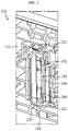
FIG. 1 is a diagram for illustrating a battery module according to an embodiment of the present disclosure. -
FIG. 2 is a diagram for illustrating a main part of the battery module ofFIG. 1 . -
FIG. 3 is a diagram for illustrating a bus bar frame, from which a sensing bus bar of a bus bar assembly ofFIG. 2 is excluded. -
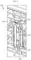
FIG. 4 is a diagram for illustrating an anti-separation stopper according to another embodiment of the present disclosure ofFIG. 1 . -
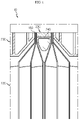
FIGS. 5 and6 are diagrams for illustrating a step difference correction between electrode leads and a sensing bus bar using an elastic guider when the electrode leads of the battery cells of the battery module ofFIG. 1 and the sensing bus bar are welded. -
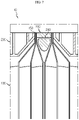
FIGS. 7 and8 are diagrams for illustrating that the damage to the electrode lead is prevented using the elastic guider when cell swelling occurs at the battery cells of the battery module ofFIG. 1 . -
FIG. 9 is a diagram for illustrating a battery pack according to an embodiment of the present disclosure. -
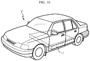
FIG. 10 is a diagram for illustrating a vehicle according to an embodiment of the present disclosure. - The present disclosure will become more apparent by describing in detail the embodiments of the present disclosure with reference to the accompanying drawings. It should be understood that the embodiments disclosed herein are illustrative only for better understanding of the present disclosure, and that the present disclosure may be modified in various ways. In addition, for ease understanding of the present disclosure, the accompanying drawings are not drawn to real scale, but the dimensions of some components may be exaggerated.
-
FIG. 1 is a diagram for illustrating a battery module according to an embodiment of the present disclosure,FIG. 2 is a diagram for illustrating a main part of the battery module ofFIG. 1 , andFIG. 3 is a diagram for illustrating a bus bar frame, from which a sensing bus bar of a bus bar assembly ofFIG. 2 is excluded. - Referring to
FIGS. 1 to 3 , abattery module 10 may include abattery cell 100 and abus bar assembly 200. - The
battery cell 100 is a secondary battery and may be provided as a pouch-type secondary battery, a rectangular secondary battery or a cylindrical secondary battery. Hereinafter, in this embodiment, it will be described that thebattery cell 100 is provided as a pouch-type secondary battery. - The
battery cell 100 may be provided in plural. The plurality ofbattery cells 100 are stacked to be electrically connected to each other, and electrode leads 150 may protrude on at least one side thereof. - The
bus bar assembly 200 is provided for electrically connecting the electrode leads 150 of the plurality ofbattery cells 100, and may be disposed at one side of the plurality ofbattery cells 100. - The
bus bar assembly 200 may include abus bar frame 210, alead slot 220, asensing bus bar 230, anelastic guider 240, and ananti-separation stopper 250. - The
bus bar frame 210 may cover at least one side of the plurality ofbattery cells 100. To this end, thebus bar frame 210 may be sized and shaped to cover at least one side of the plurality ofbattery cells 100. - The
lead slot 220 is provided to thebus bar frame 210 and may allow the electrode leads 100 of the plurality ofbattery cells 100 to pass therethrough. Thelead slot 220 may be provided in plural. - The
sensing bus bar 230 is disposed between the plurality oflead slots 220 and may be connected to the electrode leads 150 of thebattery cells 100. At least onesensing bus bar 230 or a plurality ofsensing bus bars 230 may be provided. Hereinafter, in this embodiment, it will be described that thesensing bus bar 230 is provided in plural. - The plurality of
sensing bus bars 230 may be connected with the electrode leads 150 of the plurality ofbattery cells 100 passing through thelead slots 220 by welding such as laser welding. Here, the electrode leads 150 may be welded to thesensing bus bar 230 in a non-bending manner where the electrode leads 150 are not bent. - The
elastic guider 240 may elastically support thesensing bus bar 230 and may be disposed at the rear of thesensing bus bar 230 in a front and rear directions of thebus bar frame 210. - The
elastic guider 240 may be provided in plural to correspond to the number of the sensing bus bars 230. Theelastic guider 240 may be formed integrally with thebus bar frame 210. - By means of the
elastic guider 240, the plurality ofsensing bus bars 230 may be provided to be movable along the front and rear direction of thebus bar frame 210 while elastically contacting theelastic guider 240, respectively. - The
elastic guider 240 may include afirst leaf spring 242, asecond leaf spring 244, and aspring connection portion 246. - The
first leaf spring 242 may be provided to thebus bar frame 210. Thefirst leaf spring 242 may be provided to be elastically deformable in the front and rear direction of thebus bar frame 210. - The
second leaf spring 244 may be provided to thebus bar frame 210 to be spaced apart from thefirst leaf spring 210 by a predetermined distance. Thesecond leaf spring 244 may be provided to be elastically deformable in the front and rear direction of thebus bar frame 210, like thefirst leaf spring 242. - The
spring connection portion 246 is provided to thebus bar frame 210 and may connect thefirst leaf spring 242 and thesecond leaf spring 244. Thespring connection portion 246 may be in surface contact with a rear surface of thesensing bus bar 230. - The
anti-separation stopper 250 is provided to thebus bar frame 210, and may prevent thesensing bus bar 230 from being separated forward at the front of thesensing bus bar 230 when thesensing bus bar 230 moves forward and backward. - The
anti-separation stopper 250 may include astopper hook 252 and astopper groove 254. - The
stopper hook 252 is provided above thesensing bus bar 230 and may limit a movement of a top end of thesensing bus bar 230 over a predetermined distance when thesensing bus bar 230 moves forward. - The
stopper groove 254 is provided below thesensing bus bar 230 and may limit a movement of a bottom end of thesensing bus bar 230 over a predetermined distance when thesensing bus bar 230 moves forward. -
FIG. 4 is a diagram for illustrating an anti-separation stopper according to another embodiment of the present disclosure ofFIG. 1 . - Referring to
FIG. 4 , thebus bar assembly 205 may include thestopper hook 252 in a pair. The pair of stopper hooks 252 may be provided at upper and lower sides of thesensing bus bar 230, respectively, to more effectively prevent thesensing bus bar 230 from being separated when thesensing bus bar 230 moves forward. - Hereinafter, a detailed operation of the
elastic guider 240 of thebus bar assembly 200 of thebattery module 10 according to this embodiment will be described in more detail. -
FIGS. 5 and6 are diagrams for illustrating a step difference correction between electrode leads and a sensing bus bar using an elastic guider when the electrode leads of the battery cells of the battery module ofFIG. 1 and the sensing bus bar are welded. - First, the upper and lower direction of
FIGS. 5 and6 may correspond to the front and rear direction ofFIGS. 2 to 4 . That is, the upper direction ofFIGS. 5 and6 may be the front direction ofFIGS. 2 to 4 , and the lower direction ofFIGS. 5 and6 may be the rear direction ofFIGS. 2 to 4 . Hereinafter, the upper direction inFIGS. 5 and6 will be described as a front direction, and the lower direction inFIGS. 5 and6 will be described as a rear direction. - Referring to
FIGS. 5 and6 , in thebattery module 10, when thebattery cells 100 and thebus bar assembly 200 are assembled, a predetermined step difference may occur between the electrode leads 150 of thebattery cells 100 and thesensing bus bar 230 of thebus bar assembly 200 due to an assembly tolerance or the like. - For example, the
sensing bus bar 230 of thebus bar assembly 200 may protrude forward further to the electrode leads 150 of thebattery cells 100. To correct this protrusion step difference, a worker or the like may press the protrudingsensing bus bar 230 downward using a pressing jig J. - In this embodiment, since the
sensing bus bar 230 is elastically movable in the front and rear direction of thebus bar frame 210 by means of theelastic guider 240, when the pressing jig J is pressed downward, thebus bar frame 210 may move rearward. - After that, in order to correct the step difference between the
sensing bus bar 230 and the electrode leads 150, the worker or the like may connect the electrode leads 150 and thesensing bus bar 230 to each other by welding such as laser welding. - In this embodiment, when the pressing jig J is pressed downward, the
sensing bus bar 230 is elastically movable in the front and rear direction by means of theelastic guider 240. Therefore, when the pressing jig J is pressed for correcting the step difference, a load and stress applied to the electrode leads 150 of thebattery cells 100 may be minimized. - Accordingly, in this embodiment, a damage to the electrode leads 150 of the
battery cells 100 that may occur when correcting the step difference of the pressing jig J may be effectively prevented. - As described above, the
battery module 10 according to this embodiment may prevent theelectrode lead 150 from being damaged when welding and connecting theelectrode lead 150 of thebattery cell 100 and thesensing bus bar 230 of thebus bar assembly 200, and also may effectively prevent the welding quality from deteriorating even though a protrusion step difference occurs due to an assembly tolerance or the like. -
FIGS. 7 and8 are diagrams for illustrating that the damage to the electrode lead is prevented using the elastic guider when cell swelling occurs at the battery cells of the battery module ofFIG. 1 . - In
FIGS. 7 and8 , the upper direction will be described as a front direction and the lower direction will be described as a rear direction, likeFIGS. 5 and6 . - Referring to
FIGS. 7 and8 , in thebattery module 10, thebattery cells 100 may expand in a thickness direction due to an abnormal situation caused by overheating of thebattery cells 100. That is, thebattery cells 100 may expand in a left and right direction according to cell swelling. - In this embodiment, when cell swelling occurs at the
battery cells 100, through theelastic guider 240, thesensing bus bar 230 and the ends of the electrode leads 150 welded to thesensing bus bar 230 may move elastically rearward (in a lower direction inFIG. 8 ). - As the
sensing bus bar 230 and the ends of the electrode leads 150 welded to thesensing bus bar 230 move backward, the length of the electrode leads 150 tending to increase due to cell swelling of thebattery cells 100 may be compensated. - Therefore, when cell swelling at the
battery cells 100, thebattery module 10 according to this embodiment may minimize a tensile stress applied to the electrode leads 150 to effectively prevent the electrode leads 150 from being damaged due to the tensile stress. -
FIG. 9 is a diagram for illustrating a battery pack according to an embodiment of the present disclosure, andFIG. 10 is a diagram for illustrating a vehicle according to an embodiment of the present disclosure. - Referring to
FIGS. 9 and10 , abattery pack 1 may include at least onebattery module 10 and apack case 50 for packaging the at least onebattery module 10 according to the former embodiment. - The
battery pack 1 may be provided to a vehicle V as a fuel source of the vehicle. As an example, thebattery pack 1 may be provided to an electric vehicle, a hybrid electric vehicle, and various other-type vehicles V capable of using thebattery pack 1 as a fuel source. - In addition, the
battery pack 1 may be provided in other devices, instruments or facilities such as an energy storage system using a secondary battery, in addition to the vehicle V. - As described above, the
battery pack 1 of this embodiment and devices, instruments or facilities such as the vehicle, which have thebattery pack 1, include thebattery module 10 as described above, and thus it is possible to implement abattery pack 1 having all the advantages of thebattery module 10 described above, or devices, instruments, facilities or the like such as the vehicle V, which have thebattery pack 1. - According to various embodiments as above, it is possible to provide a
battery module 10, which may prevent anelectrode lead 150 from being damaged when anelectrode lead 150 of at least onebattery cell 100 and asensing bus bar 230 of abus bar assembly battery pack 1 and a vehicle V including thebattery module 10. - In addition, according to various embodiments as above, it is possible to provide a
battery module 10, which may prevent welding quality from deteriorating even if a protrusion step difference is generated due to an assembly tolerance when theelectrode lead 150 of at least onebattery cell 100 and thesensing bus bar 230 of thebus bar assembly battery pack 1 and a vehicle V including thebattery module 10. - Moreover, according to various embodiments as above, it is possible to provide a
battery module 10, which may prevent theelectrode lead 150 from being damaged when cell swelling occurs atbattery cells 100, and abattery pack 1 and a vehicle V including thebattery module 10. - While the embodiments of the present disclosure have been shown and described, it should be understood that the present disclosure is not limited to the specific embodiments described, and that various changes and modifications can be made within the scope of the present disclosure by those skilled in the art, and these modifications should not be understood individually from the technical ideas and views of the present disclosure.
Claims (10)
- A battery module, comprising:a plurality of battery cells having electrode leads configured to protrude on at least one side thereof; anda bus bar assembly configured to electrically connect the electrode leads of the plurality of battery cells,wherein the bus bar assembly includes:a bus bar frame configured to cover at least one side of the plurality of battery cells;a plurality of lead slots provided to the bus bar frame so that the electrode leads pass therethrough;at least one sensing bus bar disposed between the plurality of lead slots and connected to the electrode leads; andat least one elastic guider configured to elastically support the at least one sensing bus bar and disposed at the rear of the at least one sensing bus bar in a front and rear direction of the bus bar frame.
- The battery module according to claim 1,
wherein the at least one sensing bus bar is configured to be movable along the front and rear direction of the bus bar frame while elastically contacting the at least one elastic guider. - The battery module according to claim 2,
wherein the at least one elastic guider includes:a first leaf spring provided to the bus bar frame and configured to be elastically deformable in the front and rear direction of the bus bar frame; anda second leaf spring provided to the bus bar frame to be spaced apart from the first leaf spring by a predetermined distance and configured to be elastically deformable in the front and rear direction of the bus bar frame. - The battery module according to claim 3,
wherein the at least one elastic guider includes a spring connection portion provided to the bus bar frame and configured to connect the first leaf spring and the second leaf spring. - The battery module according to claim 4,
wherein the spring connection portion is configured to be in surface contact with a rear surface of the at least one sensing bus bar. - The battery module according to claim 2,
wherein the at least one elastic guider is formed integrally with the bus bar frame. - The battery module according to claim 2,
wherein the bus bar assembly includes an anti-separation stopper provided to the bus bar frame and configured to prevent the at least one sensing bus bar from being separated forward at the front of the at least one sensing bus bar. - The battery module according to claim 7,
wherein the anti-separation stopper includes:a stopper hook provided above the at least one sensing bus bar and configured to limit a movement of a top end of the at least one sensing bus bar over a predetermined distance when the at least one sensing bus bar moves forward; anda stopper groove provided below the at least one sensing bus bar and configured to limit a movement of a bottom end of the at least one sensing bus bar over a predetermined distance when the at least one sensing bus bar moves forward. - A battery pack, comprising:at least one battery module as defined in claim 1; anda pack case configured to package the at least one battery module.
- A vehicle, comprising:
at least one battery pack as defined in claim 9.
Applications Claiming Priority (2)
| Application Number | Priority Date | Filing Date | Title |
|---|---|---|---|
| KR1020190132947A KR102769905B1 (en) | 2019-10-24 | 2019-10-24 | Battery module, battery pack and vehicle comprising the battery module |
| PCT/KR2020/012796 WO2021080192A1 (en) | 2019-10-24 | 2020-09-22 | Battery module, and battery pack and vehicle comprising battery module |
Publications (2)
| Publication Number | Publication Date |
|---|---|
| EP4024496A1 true EP4024496A1 (en) | 2022-07-06 |
| EP4024496A4 EP4024496A4 (en) | 2024-05-22 |
Family
ID=75619878
Family Applications (1)
| Application Number | Title | Priority Date | Filing Date |
|---|---|---|---|
| EP20879623.5A Pending EP4024496A4 (en) | 2019-10-24 | 2020-09-22 | BATTERY MODULE, AND BATTERY PACK AND VEHICLE INCLUDING SAME |
Country Status (6)
| Country | Link |
|---|---|
| US (1) | US12294115B2 (en) |
| EP (1) | EP4024496A4 (en) |
| JP (1) | JP7387874B2 (en) |
| KR (1) | KR102769905B1 (en) |
| CN (1) | CN114365342B (en) |
| WO (1) | WO2021080192A1 (en) |
Cited By (1)
| Publication number | Priority date | Publication date | Assignee | Title |
|---|---|---|---|---|
| EP4415152A4 (en) * | 2022-12-19 | 2025-01-29 | Lg Energy Solution, Ltd. | BATTERY MODULE, AND BATTERY PACK AND VEHICLE COMPRISING SAME |
Families Citing this family (5)
| Publication number | Priority date | Publication date | Assignee | Title |
|---|---|---|---|---|
| KR102710710B1 (en) * | 2022-12-19 | 2024-09-26 | 주식회사 엘지에너지솔루션 | Battery module, and battery pack and vehicle including same |
| KR20240108651A (en) * | 2023-01-02 | 2024-07-09 | 주식회사 엘지에너지솔루션 | Battery module |
| JP2026502375A (en) * | 2023-09-12 | 2026-01-22 | エルジー エナジー ソリューション リミテッド | Battery module, battery pack including same, and automobile |
| KR20250099863A (en) * | 2023-12-26 | 2025-07-03 | 주식회사 엘지에너지솔루션 | Battery module and battery pack including the same |
| KR20260046650A (en) * | 2024-09-30 | 2026-04-07 | 주식회사 엘지에너지솔루션 | A bus bar assembly, and a battery module and a battery pack including the same |
Family Cites Families (17)
| Publication number | Priority date | Publication date | Assignee | Title |
|---|---|---|---|---|
| JP4237552B2 (en) * | 2003-06-05 | 2009-03-11 | 矢崎総業株式会社 | Battery connection plate |
| JP2009022977A (en) * | 2007-07-19 | 2009-02-05 | Nec Tokin Corp | Ultrasonic welding apparatus, and manufacturing method of lithium ion secondary battery using the same |
| JP2012038558A (en) | 2010-08-06 | 2012-02-23 | Auto Network Gijutsu Kenkyusho:Kk | Cell connection structure and battery module |
| JP2013206844A (en) | 2012-03-29 | 2013-10-07 | Captex Co Ltd | Electrode connection structure in laminate cell battery |
| KR20140093424A (en) * | 2013-01-18 | 2014-07-28 | 타이코에이엠피(유) | Battery module |
| JP6011876B2 (en) * | 2013-09-13 | 2016-10-19 | 株式会社オートネットワーク技術研究所 | Power storage module |
| JP2016004611A (en) | 2014-06-13 | 2016-01-12 | パナソニックIpマネジメント株式会社 | Bus bar module and battery monitoring module |
| KR102258817B1 (en) | 2017-04-25 | 2021-06-07 | 주식회사 엘지에너지솔루션 | Battery module, battery pack comprising the battery module and vehicle comprising the battery pack |
| KR102273184B1 (en) | 2017-10-10 | 2021-07-05 | 주식회사 엘지에너지솔루션 | Bus bar assembly for connecting electrode lead and Battery module including the same |
| KR102172519B1 (en) * | 2017-10-11 | 2020-10-30 | 주식회사 엘지화학 | Bus bar assembly for connecting electrode lead and Battery module including the same |
| KR102198848B1 (en) | 2017-11-16 | 2021-01-05 | 주식회사 엘지화학 | Battery Module Having Sensing Assembly and Busbar Assembly |
| KR102258819B1 (en) | 2017-11-24 | 2021-05-31 | 주식회사 엘지에너지솔루션 | Battery Module with improved electrical connection safety |
| JP6888690B2 (en) | 2017-11-29 | 2021-06-16 | 日産自動車株式会社 | Fuel cell stack |
| KR102364283B1 (en) | 2017-12-01 | 2022-02-16 | 주식회사 엘지에너지솔루션 | Battery Module Having Heat Dissipation Plate |
| JP7081237B2 (en) | 2018-03-16 | 2022-06-07 | 株式会社オートネットワーク技術研究所 | Connection module and power storage module |
| KR102225902B1 (en) | 2018-05-21 | 2021-03-10 | 주식회사 엘지화학 | Polarizing plate, image display apparatus comprising same and adhesive composition for plarizing plate |
| CN208955084U (en) | 2018-09-28 | 2019-06-07 | 桑顿新能源科技有限公司 | A kind of power battery tab, busbar connector welding structure and power battery module |
-
2019
- 2019-10-24 KR KR1020190132947A patent/KR102769905B1/en active Active
-
2020
- 2020-09-22 JP JP2022509693A patent/JP7387874B2/en active Active
- 2020-09-22 US US17/768,982 patent/US12294115B2/en active Active
- 2020-09-22 EP EP20879623.5A patent/EP4024496A4/en active Pending
- 2020-09-22 WO PCT/KR2020/012796 patent/WO2021080192A1/en not_active Ceased
- 2020-09-22 CN CN202080063414.2A patent/CN114365342B/en active Active
Cited By (1)
| Publication number | Priority date | Publication date | Assignee | Title |
|---|---|---|---|---|
| EP4415152A4 (en) * | 2022-12-19 | 2025-01-29 | Lg Energy Solution, Ltd. | BATTERY MODULE, AND BATTERY PACK AND VEHICLE COMPRISING SAME |
Also Published As
| Publication number | Publication date |
|---|---|
| WO2021080192A1 (en) | 2021-04-29 |
| US12294115B2 (en) | 2025-05-06 |
| US20230143366A1 (en) | 2023-05-11 |
| CN114365342A (en) | 2022-04-15 |
| JP2022544608A (en) | 2022-10-19 |
| CN114365342B (en) | 2024-10-11 |
| KR102769905B1 (en) | 2025-02-17 |
| KR20210048811A (en) | 2021-05-04 |
| EP4024496A4 (en) | 2024-05-22 |
| JP7387874B2 (en) | 2023-11-28 |
Similar Documents
| Publication | Publication Date | Title |
|---|---|---|
| US12294115B2 (en) | Battery module, and battery pack and vehicle comprising battery module | |
| EP3836244B1 (en) | Battery module and battery pack comprising battery module | |
| US12315956B2 (en) | Battery module, battery pack comprising same, and vehicle | |
| US10603747B2 (en) | Lead welding apparatus, battery module manufactured by the lead welding apparatus, and battery pack comprising the battery module | |
| US10497911B2 (en) | Battery module, battery pack including battery module, and automobile including battery pack | |
| US10625619B2 (en) | Battery module, battery pack comprising battery module, and vehicle comprising battery pack | |
| US11362402B2 (en) | Battery module, battery pack including the same, and method for producing battery module | |
| US11456502B2 (en) | Battery module, battery pack comprising same battery module, and vehicle comprising same battery pack | |
| US20200381691A1 (en) | Battery module and battery pack including the same | |
| EP3561902A1 (en) | Battery module, battery pack comprising battery module, and vehicle comprising battery pack | |
| US12614817B2 (en) | Battery module comprising bus bar assembly with elastic guiders, and battery pack and vehicle comprising same battery module | |
| KR102378571B1 (en) | Battery module, battery pack and vehicle comprising the same |
Legal Events
| Date | Code | Title | Description |
|---|---|---|---|
| STAA | Information on the status of an ep patent application or granted ep patent |
Free format text: STATUS: THE INTERNATIONAL PUBLICATION HAS BEEN MADE |
|
| PUAI | Public reference made under article 153(3) epc to a published international application that has entered the european phase |
Free format text: ORIGINAL CODE: 0009012 |
|
| STAA | Information on the status of an ep patent application or granted ep patent |
Free format text: STATUS: REQUEST FOR EXAMINATION WAS MADE |
|
| 17P | Request for examination filed |
Effective date: 20220328 |
|
| AK | Designated contracting states |
Kind code of ref document: A1 Designated state(s): AL AT BE BG CH CY CZ DE DK EE ES FI FR GB GR HR HU IE IS IT LI LT LU LV MC MK MT NL NO PL PT RO RS SE SI SK SM TR |
|
| DAV | Request for validation of the european patent (deleted) | ||
| DAX | Request for extension of the european patent (deleted) | ||
| REG | Reference to a national code |
Ref country code: DE Ref legal event code: R079 Free format text: PREVIOUS MAIN CLASS: H99Z9999999999 Ipc: H01M0050209000 |
|
| A4 | Supplementary search report drawn up and despatched |
Effective date: 20240424 |
|
| RIC1 | Information provided on ipc code assigned before grant |
Ipc: H01M 50/105 20210101ALN20240418BHEP Ipc: H01M 50/557 20210101ALI20240418BHEP Ipc: H01M 50/507 20210101ALI20240418BHEP Ipc: H01M 50/209 20210101AFI20240418BHEP |