EP4024113B1 - Endoscope system and method for operating same - Google Patents
Endoscope system and method for operating same Download PDFInfo
- Publication number
- EP4024113B1 EP4024113B1 EP20858181.9A EP20858181A EP4024113B1 EP 4024113 B1 EP4024113 B1 EP 4024113B1 EP 20858181 A EP20858181 A EP 20858181A EP 4024113 B1 EP4024113 B1 EP 4024113B1
- Authority
- EP
- European Patent Office
- Prior art keywords
- image
- measurement
- subject
- light
- irradiation region
- Prior art date
- Legal status (The legal status is an assumption and is not a legal conclusion. Google has not performed a legal analysis and makes no representation as to the accuracy of the status listed.)
- Active
Links
Images








Classifications
-
- A—HUMAN NECESSITIES
- A61—MEDICAL OR VETERINARY SCIENCE; HYGIENE
- A61B—DIAGNOSIS; SURGERY; IDENTIFICATION
- A61B1/00—Instruments for performing medical examinations of the interior of cavities or tubes of the body by visual or photographical inspection, e.g. endoscopes; Illuminating arrangements therefor
- A61B1/06—Instruments for performing medical examinations of the interior of cavities or tubes of the body by visual or photographical inspection, e.g. endoscopes; Illuminating arrangements therefor with illuminating arrangements
- A61B1/0655—Control therefor
-
- A—HUMAN NECESSITIES
- A61—MEDICAL OR VETERINARY SCIENCE; HYGIENE
- A61B—DIAGNOSIS; SURGERY; IDENTIFICATION
- A61B1/00—Instruments for performing medical examinations of the interior of cavities or tubes of the body by visual or photographical inspection, e.g. endoscopes; Illuminating arrangements therefor
- A61B1/00002—Operational features of endoscopes
- A61B1/00004—Operational features of endoscopes characterised by electronic signal processing
- A61B1/00009—Operational features of endoscopes characterised by electronic signal processing of image signals during a use of endoscope
- A61B1/000096—Operational features of endoscopes characterised by electronic signal processing of image signals during a use of endoscope using artificial intelligence
-
- A—HUMAN NECESSITIES
- A61—MEDICAL OR VETERINARY SCIENCE; HYGIENE
- A61B—DIAGNOSIS; SURGERY; IDENTIFICATION
- A61B1/00—Instruments for performing medical examinations of the interior of cavities or tubes of the body by visual or photographical inspection, e.g. endoscopes; Illuminating arrangements therefor
- A61B1/00064—Constructional details of the endoscope body
- A61B1/00071—Insertion part of the endoscope body
- A61B1/0008—Insertion part of the endoscope body characterised by distal tip features
- A61B1/00096—Optical elements
-
- A—HUMAN NECESSITIES
- A61—MEDICAL OR VETERINARY SCIENCE; HYGIENE
- A61B—DIAGNOSIS; SURGERY; IDENTIFICATION
- A61B1/00—Instruments for performing medical examinations of the interior of cavities or tubes of the body by visual or photographical inspection, e.g. endoscopes; Illuminating arrangements therefor
- A61B1/06—Instruments for performing medical examinations of the interior of cavities or tubes of the body by visual or photographical inspection, e.g. endoscopes; Illuminating arrangements therefor with illuminating arrangements
- A61B1/0605—Instruments for performing medical examinations of the interior of cavities or tubes of the body by visual or photographical inspection, e.g. endoscopes; Illuminating arrangements therefor with illuminating arrangements for spatially modulated illumination
-
- A—HUMAN NECESSITIES
- A61—MEDICAL OR VETERINARY SCIENCE; HYGIENE
- A61B—DIAGNOSIS; SURGERY; IDENTIFICATION
- A61B1/00—Instruments for performing medical examinations of the interior of cavities or tubes of the body by visual or photographical inspection, e.g. endoscopes; Illuminating arrangements therefor
- A61B1/06—Instruments for performing medical examinations of the interior of cavities or tubes of the body by visual or photographical inspection, e.g. endoscopes; Illuminating arrangements therefor with illuminating arrangements
- A61B1/0623—Instruments for performing medical examinations of the interior of cavities or tubes of the body by visual or photographical inspection, e.g. endoscopes; Illuminating arrangements therefor with illuminating arrangements for off-axis illumination
-
- A—HUMAN NECESSITIES
- A61—MEDICAL OR VETERINARY SCIENCE; HYGIENE
- A61B—DIAGNOSIS; SURGERY; IDENTIFICATION
- A61B1/00—Instruments for performing medical examinations of the interior of cavities or tubes of the body by visual or photographical inspection, e.g. endoscopes; Illuminating arrangements therefor
- A61B1/06—Instruments for performing medical examinations of the interior of cavities or tubes of the body by visual or photographical inspection, e.g. endoscopes; Illuminating arrangements therefor with illuminating arrangements
- A61B1/0638—Instruments for performing medical examinations of the interior of cavities or tubes of the body by visual or photographical inspection, e.g. endoscopes; Illuminating arrangements therefor with illuminating arrangements providing two or more wavelengths
-
- G—PHYSICS
- G02—OPTICS
- G02B—OPTICAL ELEMENTS, SYSTEMS OR APPARATUS
- G02B23/00—Telescopes, e.g. binoculars; Periscopes; Instruments for viewing the inside of hollow bodies; Viewfinders; Optical aiming or sighting devices
- G02B23/24—Instruments or systems for viewing the inside of hollow bodies, e.g. fibrescopes
- G02B23/26—Instruments or systems for viewing the inside of hollow bodies, e.g. fibrescopes using light guides
Definitions
- the present invention relates to an endoscope system that displays a measurement marker to be used to measure the size of a subject and a method of operating the endoscope system.
- programs related to various types of processing are incorporated into a program memory (not shown).
- the programs incorporated into the program memory are operated by the system controller 41 formed of a processor, so that the processor device 16 realizes the functions of a reception unit 38, a signal processing unit 39, and a display controller 40.
- the reception unit 38 is connected to the communication interface (I/F) 37 of the light source device 14.
- the reception unit 38 receives the image signals, which are transmitted from the communication I/F 37, and transmits the image signals to the signal processing unit 39.
- a memory which temporarily stores the image signals received from the reception unit 38, is built in the signal processing unit 39, and the signal processing unit 39 processes an image signal group, which is a set of the image signals stored in the memory, to generate the subject image.
- the reception unit 38 may directly transmit control signals, which are related to the light source controller 27, to the system controller 41.
- the display controller 40 causes the display 18 to display the subject image that is generated by the signal processing unit 39.
- the system controller 41 performs the control of the image pickup element 32 through the image pickup controller 33 provided in the endoscope 12.
- the image pickup controller 33 also performs the control of the CDS/AGC circuit 34 and the A/D converter 35 together with the control of the image pickup element 32.
- the beam light-emitting unit 23 emits measurement beam light Lm obliquely with respect to the optical axis Ax (see Fig. 7 ) of the image pickup optical system 21.
- the beam light-emitting unit 23 comprises a light source 23a, a diffractive optical element (DOE) 23b, a prism 23c, and an emitting section 23d.
- DOE diffractive optical element
- the pattern matching-processing section 60 can also perform pattern matching processing using the pattern of the feature quantity of the peripheral region SR1.
- a feature quantity, which can be subjected to pattern matching processing includes the distribution of a blue color or a green color other than the distribution of a red color that is the color of the measurement beam light.
- a feature quantity, which can be subjected to pattern matching processing includes the distribution of the luminance, brightness, chroma saturation, or hue of the measurement beam light.
- the display controller 40 causes the display 18 to display the measurement image in which a measurement marker is displayed in the subject image on the basis of the position of the spot SP that is a beam irradiation region. Specifically, the display controller 40 causes the display 18 to display the measurement image in which the first measurement marker is superimposed to center on the spot SP.
- a circular measurement marker is used as the first measurement marker.
- a marker M1 which shows an actual size of 5 mm (a horizontal direction and a vertical direction of the subject image)
- an observation distance may also be displayed on the display 18 together.
- a marker M2 which shows an actual size of 5 mm (the horizontal direction and the vertical direction of the subject image), is displayed at the center of a spot SP2 formed on a tumor tm2 of a subject in a case where an observation distance is close to the intermediate vicinity Py. Since the marker display position of the marker M2 is positioned at the central portion of the subject image that is less likely to be affected by distortion caused by the image pickup optical system 21, the marker M2 has a circular shape without being affected by the distortion or the like.
- a marker M3 which shows an actual size of 5 mm (the horizontal direction and the vertical direction of the subject image), is displayed at the center of a spot SP3 formed on a tumor tm3 of a subject.
- the size of the first measurement marker corresponding to the same actual size of 5 mm is reduced with an increase in an observation distance.
- the shape of the first measurement marker also varies depending on the marker display position due to an influence of the distortion caused by the image pickup optical system 21.
- the center of the spot SP and the center of the marker are displayed to coincide with each other.
- the first measurement marker may be displayed at a position away from the spot SP in a case where there is no problem in measurement accuracy. Even in this case, it is preferable that the first measurement marker is displayed near the spot.
- the first measurement marker corresponding to the actual size of the subject which is 5 mm, is displayed in Figs. 15 to 17 , but the actual size of the subject may be set to any value (for example, 2 mm, 3 mm, 10 mm, or the like) according to an object to be observed or the purpose of observation.
- the first measurement marker has a substantially circular shape in Figs. 15 to 17 , but may have a cruciform shape where a vertical line and a horizontal line intersect with each other as shown in Fig. 18 .
- the first measurement marker may have a cruciform shape with gradations where gradations Mx are given to at least one of a vertical line or a horizontal line of a cruciform shape.
- the first measurement marker may have a distorted cruciform shape of which at least one of a vertical line or a horizontal line is inclined. Furthermore, the first measurement marker may have a circular-and-cruciform shape where a cruciform shape and a circle are combined with each other. In addition, the first measurement marker may have the shape of a measurement point group where a plurality of measurement points EP corresponding to an actual size from a spot are combined with each other. Further, one first measurement marker may be displayed or a plurality of first measurement markers may be displayed, and the color of the first measurement marker may be changed according to an actual size.
- three concentric circular markers M4A, M4B, and M4C having different sizes may be displayed in the subject image as the first measurement marker to center on a spot SP4 formed on a tumor tm4. Since the three concentric circular markers are displayed as a plurality of markers, time and effort required to switch a marker can be saved and measurement can be performed even in a case where a subject has a non-linear shape. In a case where a plurality of concentric circular markers are to be displayed to center on a spot, a size and a color are not designated for each marker and combinations of a plurality of conditions may be prepared in advance and one can be selected from these combinations.
- a marker M5A is displayed by a dotted line representing a red color
- a marker M5B is displayed by a solid line representing a blue color
- a marker M5C is displayed by a one-dot chain line representing a white color. Since identifiability can be improved in a case where the colors of the markers are different from each other in this way, measurement can be easily performed.
- a plurality of distorted concentric circular markers which are distorted from the respective concentric circles, may be used as the first measurement marker other than the plurality of concentric circular markers.
- distorted concentric circular markers M6A, M6B, and M6C are displayed in the subject image to center on a spot SP5 formed on a tumor tm5.
- Light which forms a spot in a case where a subject is irradiated with the light, is used as the measurement beam light, but other light may be used.
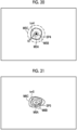
- plane measurement beam light which forms an intersection line 80 on the subject as shown in Fig. 22 in a case where the subject is irradiated with the light, may be used.
- the intersection line 80 as a line-like beam irradiation region is formed on the subject.
- a second measurement marker that consists of the intersection line 80 and gradations 82 formed on the intersection line 80 and serving as an index of the size of the subject (for example, a polyp P) is generated as a measurement marker.
- the irradiation region-recognizing section 58 recognizes the position of the intersection line 80 (the irradiation position of the measurement beam light) as the beam irradiation region that has the pattern having a specific shape.
- the intersection line 80 includes a white central region CR2 and a peripheral region SR2 that covers the white central region R2 and has a feature quantity based on the measurement beam light.
- the central region CR2 has a linear shape
- the peripheral region SR2 is formed in the shape of two lines that are spaced from each other with a specific interval therebetween.
- the irradiation region-recognizing section 58 can recognize the intersection line 80 that has the pattern and the feature quantity described above.
- An intersection line 80 that has a shape deformed from a linear shape, such as a shape in which a part or the like of a line is cut out can also be recognized by the irradiation region-recognizing section 58.
- the observation distance is shorter as the intersection line 80 recognized by the irradiation region-recognizing section 58 is positioned closer to the lower side, and the observation distance is longer as the intersection line 80 is positioned closer to the upper side. For this reason, in a case where the second measurement marker is displayed in the measurement image, an interval between the gradations 82 is larger as the intersection line 80 is positioned closer to the lower side and an interval between the gradations 82 is smaller as the intersection line 80 is positioned closer to the upper side.
- a measurement marker corresponding to the position of a beam irradiation region such as the spot SP or the intersection line 80, has been displayed in the measurement image.
- a measurement marker corresponding to the pattern of a beam irradiation region may be displayed in the measurement image instead of this.
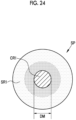
- a diameter DM of the white central region CR1 of the spot SP is obtained as shown in Fig. 24 and a measurement marker corresponding to the diameter DM is displayed in the measurement image.
- the diameter DM is large in a case where an observation distance is short, and the diameter is reduced as an observation distance is increased.
- a measurement marker image of which the size, shape, or the like varies depending on the diameter DM is determined using a relationship between the diameter DM and an observation distance.
- the reception unit 38 receives the subject image output from the endoscope 12.
- the irradiation region-recognizing section 58 recognizes the position of the spot SP from the subject image. In this case, the irradiation region-recognizing section 58 recognizes the position of the spot SP that includes the white central region CR1 and the peripheral region SR1 covering the periphery of the central region CR1 and having a feature quantity based on the measurement beam light.
- the display controller 40 causes the display 18 to display a measurement image in which a measurement marker to be used to measure the size of the subject is displayed in the subject image on the basis of the position of the spot SP recognized by the irradiation region-recognizing section 58.
- the measurement marker corresponds to the position of the spot SP, and the size, shape, or the like is changed depending on the position of the spot SP.
- the hardware structures of these various processors are more specifically electrical circuitry where circuit elements, such as semiconductor elements, are combined.
- the hardware structure of the storage unit is a storage device, such as a hard disc drive (HDD) or a solid state drive (SSD).
Landscapes
- Health & Medical Sciences (AREA)
- Life Sciences & Earth Sciences (AREA)
- Surgery (AREA)
- Engineering & Computer Science (AREA)
- Medical Informatics (AREA)
- Biomedical Technology (AREA)
- Animal Behavior & Ethology (AREA)
- Radiology & Medical Imaging (AREA)
- Optics & Photonics (AREA)
- Nuclear Medicine, Radiotherapy & Molecular Imaging (AREA)
- Physics & Mathematics (AREA)
- Heart & Thoracic Surgery (AREA)
- Biophysics (AREA)
- Molecular Biology (AREA)
- Pathology (AREA)
- General Health & Medical Sciences (AREA)
- Public Health (AREA)
- Veterinary Medicine (AREA)
- Artificial Intelligence (AREA)
- Evolutionary Computation (AREA)
- Signal Processing (AREA)
- Endoscopes (AREA)
Applications Claiming Priority (2)
| Application Number | Priority Date | Filing Date | Title |
|---|---|---|---|
| JP2019155553 | 2019-08-28 | ||
| PCT/JP2020/031845 WO2021039718A1 (ja) | 2019-08-28 | 2020-08-24 | 内視鏡システム及びその作動方法 |
Publications (3)
| Publication Number | Publication Date |
|---|---|
| EP4024113A1 EP4024113A1 (en) | 2022-07-06 |
| EP4024113A4 EP4024113A4 (en) | 2022-10-12 |
| EP4024113B1 true EP4024113B1 (en) | 2025-06-25 |
Family
ID=74684192
Family Applications (1)
| Application Number | Title | Priority Date | Filing Date |
|---|---|---|---|
| EP20858181.9A Active EP4024113B1 (en) | 2019-08-28 | 2020-08-24 | Endoscope system and method for operating same |
Country Status (4)
| Country | Link |
|---|---|
| EP (1) | EP4024113B1 (https=) |
| JP (1) | JP7167352B2 (https=) |
| CN (1) | CN114286961B (https=) |
| WO (1) | WO2021039718A1 (https=) |
Families Citing this family (3)
| Publication number | Priority date | Publication date | Assignee | Title |
|---|---|---|---|---|
| JP7741004B2 (ja) * | 2022-02-01 | 2025-09-17 | 富士フイルム株式会社 | 内視鏡システム及びその作動方法 |
| CN116048249A (zh) * | 2022-12-20 | 2023-05-02 | 上海澳华内镜股份有限公司 | 内窥镜操作系统 |
| CN119055163B (zh) * | 2024-11-04 | 2025-02-25 | 湖南省华芯医疗器械有限公司 | 一种前端组件及内窥镜 |
Family Cites Families (9)
| Publication number | Priority date | Publication date | Assignee | Title |
|---|---|---|---|---|
| JP3186161B2 (ja) * | 1992-01-27 | 2001-07-11 | オリンパス光学工業株式会社 | 内視鏡の照明光学系 |
| US20060226231A1 (en) * | 2005-03-29 | 2006-10-12 | University Of Washington | Methods and systems for creating sequential color images |
| JP2009240621A (ja) * | 2008-03-31 | 2009-10-22 | Hoya Corp | 内視鏡装置 |
| JP5305946B2 (ja) * | 2009-01-27 | 2013-10-02 | 富士フイルム株式会社 | ライトガイド及び光源装置並びに内視鏡システム |
| JP6144914B2 (ja) * | 2010-02-12 | 2017-06-07 | コーニンクレッカ フィリップス エヌ ヴェKoninklijke Philips N.V. | レーザ改良された3d表面再構成 |
| JP6964592B2 (ja) * | 2016-09-15 | 2021-11-10 | 富士フイルム株式会社 | 計測支援装置、内視鏡システム、内視鏡システムのプロセッサ、及び計測支援方法 |
| JP6692440B2 (ja) * | 2016-09-15 | 2020-05-13 | 富士フイルム株式会社 | 内視鏡システム |
| WO2018055933A1 (ja) * | 2016-09-20 | 2018-03-29 | 富士フイルム株式会社 | 計測支援装置、内視鏡システム、内視鏡システムのプロセッサ、及び計測支援方法 |
| CN110418596B (zh) * | 2017-03-28 | 2021-12-24 | 富士胶片株式会社 | 测量辅助装置、内窥镜系统及处理器 |
-
2020
- 2020-08-24 CN CN202080060690.3A patent/CN114286961B/zh active Active
- 2020-08-24 JP JP2021542889A patent/JP7167352B2/ja active Active
- 2020-08-24 WO PCT/JP2020/031845 patent/WO2021039718A1/ja not_active Ceased
- 2020-08-24 EP EP20858181.9A patent/EP4024113B1/en active Active
Also Published As
| Publication number | Publication date |
|---|---|
| JP7167352B2 (ja) | 2022-11-08 |
| EP4024113A4 (en) | 2022-10-12 |
| JPWO2021039718A1 (https=) | 2021-03-04 |
| EP4024113A1 (en) | 2022-07-06 |
| WO2021039718A1 (ja) | 2021-03-04 |
| CN114286961A (zh) | 2022-04-05 |
| CN114286961B (zh) | 2025-02-25 |
Similar Documents
| Publication | Publication Date | Title |
|---|---|---|
| EP4024113B1 (en) | Endoscope system and method for operating same | |
| EP3571976B1 (en) | Endoscope apparatus | |
| EP3586719B1 (en) | Endoscope apparatus | |
| EP3705023B1 (en) | Endoscope apparatus, calibration device, and calibration method | |
| US12471804B2 (en) | Endoscope apparatus, method of operating the same, and non-transitory computer readable medium | |
| EP4016162B1 (en) | Endoscope system and method for operating same | |
| CN114286641B (zh) | 内窥镜装置及其工作方法以及计算机可读介质 | |
| US11957316B2 (en) | Endoscope apparatus | |
| EP3698714B1 (en) | Endoscope apparatus | |
| US11399707B2 (en) | Endoscope apparatus | |
| JP2022181645A (ja) | 内視鏡業務支援装置及び内視鏡業務支援システム並びに内視鏡業務支援装置の作動方法 | |
| JP2020014808A (ja) | 内視鏡装置及びその作動方法並び内視鏡装置用プログラム | |
| JP2020014807A (ja) | 内視鏡装置及びその作動方法並び内視鏡装置用プログラム | |
| EP3951473A1 (en) | Endoscope and endoscopic device |
Legal Events
| Date | Code | Title | Description |
|---|---|---|---|
| STAA | Information on the status of an ep patent application or granted ep patent |
Free format text: STATUS: THE INTERNATIONAL PUBLICATION HAS BEEN MADE |
|
| PUAI | Public reference made under article 153(3) epc to a published international application that has entered the european phase |
Free format text: ORIGINAL CODE: 0009012 |
|
| STAA | Information on the status of an ep patent application or granted ep patent |
Free format text: STATUS: REQUEST FOR EXAMINATION WAS MADE |
|
| 17P | Request for examination filed |
Effective date: 20220228 |
|
| AK | Designated contracting states |
Kind code of ref document: A1 Designated state(s): AL AT BE BG CH CY CZ DE DK EE ES FI FR GB GR HR HU IE IS IT LI LT LU LV MC MK MT NL NO PL PT RO RS SE SI SK SM TR |
|
| A4 | Supplementary search report drawn up and despatched |
Effective date: 20220909 |
|
| RIC1 | Information provided on ipc code assigned before grant |
Ipc: A61B 1/06 20060101ALI20220905BHEP Ipc: A61B 1/00 20060101ALI20220905BHEP Ipc: G02B 23/26 20060101ALI20220905BHEP Ipc: G02B 23/24 20060101AFI20220905BHEP |
|
| DAV | Request for validation of the european patent (deleted) | ||
| DAX | Request for extension of the european patent (deleted) | ||
| GRAP | Despatch of communication of intention to grant a patent |
Free format text: ORIGINAL CODE: EPIDOSNIGR1 |
|
| STAA | Information on the status of an ep patent application or granted ep patent |
Free format text: STATUS: GRANT OF PATENT IS INTENDED |
|
| INTG | Intention to grant announced |
Effective date: 20250213 |
|
| P01 | Opt-out of the competence of the unified patent court (upc) registered |
Free format text: CASE NUMBER: APP_16068/2025 Effective date: 20250402 |
|
| GRAS | Grant fee paid |
Free format text: ORIGINAL CODE: EPIDOSNIGR3 |
|
| GRAA | (expected) grant |
Free format text: ORIGINAL CODE: 0009210 |
|
| STAA | Information on the status of an ep patent application or granted ep patent |
Free format text: STATUS: THE PATENT HAS BEEN GRANTED |
|
| AK | Designated contracting states |
Kind code of ref document: B1 Designated state(s): AL AT BE BG CH CY CZ DE DK EE ES FI FR GB GR HR HU IE IS IT LI LT LU LV MC MK MT NL NO PL PT RO RS SE SI SK SM TR |
|
| REG | Reference to a national code |
Ref country code: GB Ref legal event code: FG4D |
|
| REG | Reference to a national code |
Ref country code: CH Ref legal event code: EP |
|
| REG | Reference to a national code |
Ref country code: CH Ref legal event code: EP |
|
| REG | Reference to a national code |
Ref country code: IE Ref legal event code: FG4D |
|
| REG | Reference to a national code |
Ref country code: DE Ref legal event code: R096 Ref document number: 602020053478 Country of ref document: DE |
|
| PG25 | Lapsed in a contracting state [announced via postgrant information from national office to epo] |
Ref country code: FI Free format text: LAPSE BECAUSE OF FAILURE TO SUBMIT A TRANSLATION OF THE DESCRIPTION OR TO PAY THE FEE WITHIN THE PRESCRIBED TIME-LIMIT Effective date: 20250625 |
|
| PGFP | Annual fee paid to national office [announced via postgrant information from national office to epo] |
Ref country code: DE Payment date: 20250722 Year of fee payment: 6 |
|
| REG | Reference to a national code |
Ref country code: LT Ref legal event code: MG9D |
|
| PG25 | Lapsed in a contracting state [announced via postgrant information from national office to epo] |
Ref country code: NO Free format text: LAPSE BECAUSE OF FAILURE TO SUBMIT A TRANSLATION OF THE DESCRIPTION OR TO PAY THE FEE WITHIN THE PRESCRIBED TIME-LIMIT Effective date: 20250925 Ref country code: GR Free format text: LAPSE BECAUSE OF FAILURE TO SUBMIT A TRANSLATION OF THE DESCRIPTION OR TO PAY THE FEE WITHIN THE PRESCRIBED TIME-LIMIT Effective date: 20250926 |
|
| PG25 | Lapsed in a contracting state [announced via postgrant information from national office to epo] |
Ref country code: BG Free format text: LAPSE BECAUSE OF FAILURE TO SUBMIT A TRANSLATION OF THE DESCRIPTION OR TO PAY THE FEE WITHIN THE PRESCRIBED TIME-LIMIT Effective date: 20250625 |
|
| PG25 | Lapsed in a contracting state [announced via postgrant information from national office to epo] |
Ref country code: HR Free format text: LAPSE BECAUSE OF FAILURE TO SUBMIT A TRANSLATION OF THE DESCRIPTION OR TO PAY THE FEE WITHIN THE PRESCRIBED TIME-LIMIT Effective date: 20250625 |
|
| PG25 | Lapsed in a contracting state [announced via postgrant information from national office to epo] |
Ref country code: RS Free format text: LAPSE BECAUSE OF FAILURE TO SUBMIT A TRANSLATION OF THE DESCRIPTION OR TO PAY THE FEE WITHIN THE PRESCRIBED TIME-LIMIT Effective date: 20250925 |
|
| PG25 | Lapsed in a contracting state [announced via postgrant information from national office to epo] |
Ref country code: LV Free format text: LAPSE BECAUSE OF FAILURE TO SUBMIT A TRANSLATION OF THE DESCRIPTION OR TO PAY THE FEE WITHIN THE PRESCRIBED TIME-LIMIT Effective date: 20250625 |
|
| REG | Reference to a national code |
Ref country code: NL Ref legal event code: MP Effective date: 20250625 |
|
| PG25 | Lapsed in a contracting state [announced via postgrant information from national office to epo] |
Ref country code: NL Free format text: LAPSE BECAUSE OF FAILURE TO SUBMIT A TRANSLATION OF THE DESCRIPTION OR TO PAY THE FEE WITHIN THE PRESCRIBED TIME-LIMIT Effective date: 20250625 |
|
| PG25 | Lapsed in a contracting state [announced via postgrant information from national office to epo] |
Ref country code: PT Free format text: LAPSE BECAUSE OF FAILURE TO SUBMIT A TRANSLATION OF THE DESCRIPTION OR TO PAY THE FEE WITHIN THE PRESCRIBED TIME-LIMIT Effective date: 20251027 |
|
| REG | Reference to a national code |
Ref country code: AT Ref legal event code: MK05 Ref document number: 1807053 Country of ref document: AT Kind code of ref document: T Effective date: 20250625 |
|
| PG25 | Lapsed in a contracting state [announced via postgrant information from national office to epo] |
Ref country code: IS Free format text: LAPSE BECAUSE OF FAILURE TO SUBMIT A TRANSLATION OF THE DESCRIPTION OR TO PAY THE FEE WITHIN THE PRESCRIBED TIME-LIMIT Effective date: 20251025 |
|
| PG25 | Lapsed in a contracting state [announced via postgrant information from national office to epo] |
Ref country code: AT Free format text: LAPSE BECAUSE OF FAILURE TO SUBMIT A TRANSLATION OF THE DESCRIPTION OR TO PAY THE FEE WITHIN THE PRESCRIBED TIME-LIMIT Effective date: 20250625 Ref country code: SM Free format text: LAPSE BECAUSE OF FAILURE TO SUBMIT A TRANSLATION OF THE DESCRIPTION OR TO PAY THE FEE WITHIN THE PRESCRIBED TIME-LIMIT Effective date: 20250625 |
|
| PG25 | Lapsed in a contracting state [announced via postgrant information from national office to epo] |
Ref country code: CZ Free format text: LAPSE BECAUSE OF FAILURE TO SUBMIT A TRANSLATION OF THE DESCRIPTION OR TO PAY THE FEE WITHIN THE PRESCRIBED TIME-LIMIT Effective date: 20250625 |
|
| PG25 | Lapsed in a contracting state [announced via postgrant information from national office to epo] |
Ref country code: PL Free format text: LAPSE BECAUSE OF FAILURE TO SUBMIT A TRANSLATION OF THE DESCRIPTION OR TO PAY THE FEE WITHIN THE PRESCRIBED TIME-LIMIT Effective date: 20250625 |
|
| PG25 | Lapsed in a contracting state [announced via postgrant information from national office to epo] |
Ref country code: EE Free format text: LAPSE BECAUSE OF FAILURE TO SUBMIT A TRANSLATION OF THE DESCRIPTION OR TO PAY THE FEE WITHIN THE PRESCRIBED TIME-LIMIT Effective date: 20250625 |
|
| PG25 | Lapsed in a contracting state [announced via postgrant information from national office to epo] |
Ref country code: SK Free format text: LAPSE BECAUSE OF FAILURE TO SUBMIT A TRANSLATION OF THE DESCRIPTION OR TO PAY THE FEE WITHIN THE PRESCRIBED TIME-LIMIT Effective date: 20250625 |
|
| PG25 | Lapsed in a contracting state [announced via postgrant information from national office to epo] |
Ref country code: ES Free format text: LAPSE BECAUSE OF FAILURE TO SUBMIT A TRANSLATION OF THE DESCRIPTION OR TO PAY THE FEE WITHIN THE PRESCRIBED TIME-LIMIT Effective date: 20250625 |
|
| PG25 | Lapsed in a contracting state [announced via postgrant information from national office to epo] |
Ref country code: RO Free format text: LAPSE BECAUSE OF FAILURE TO SUBMIT A TRANSLATION OF THE DESCRIPTION OR TO PAY THE FEE WITHIN THE PRESCRIBED TIME-LIMIT Effective date: 20250625 |
|
| REG | Reference to a national code |
Ref country code: CH Ref legal event code: H13 Free format text: ST27 STATUS EVENT CODE: U-0-0-H10-H13 (AS PROVIDED BY THE NATIONAL OFFICE) Effective date: 20260324 |
|
| PG25 | Lapsed in a contracting state [announced via postgrant information from national office to epo] |
Ref country code: MC Free format text: LAPSE BECAUSE OF FAILURE TO SUBMIT A TRANSLATION OF THE DESCRIPTION OR TO PAY THE FEE WITHIN THE PRESCRIBED TIME-LIMIT Effective date: 20250625 |
|
| PG25 | Lapsed in a contracting state [announced via postgrant information from national office to epo] |
Ref country code: DK Free format text: LAPSE BECAUSE OF FAILURE TO SUBMIT A TRANSLATION OF THE DESCRIPTION OR TO PAY THE FEE WITHIN THE PRESCRIBED TIME-LIMIT Effective date: 20250625 |
|
| PG25 | Lapsed in a contracting state [announced via postgrant information from national office to epo] |
Ref country code: IT Free format text: LAPSE BECAUSE OF FAILURE TO SUBMIT A TRANSLATION OF THE DESCRIPTION OR TO PAY THE FEE WITHIN THE PRESCRIBED TIME-LIMIT Effective date: 20250625 Ref country code: LU Free format text: LAPSE BECAUSE OF NON-PAYMENT OF DUE FEES Effective date: 20250824 |
|
| PG25 | Lapsed in a contracting state [announced via postgrant information from national office to epo] |
Ref country code: CH Free format text: LAPSE BECAUSE OF NON-PAYMENT OF DUE FEES Effective date: 20250831 |
|
| PLBE | No opposition filed within time limit |
Free format text: ORIGINAL CODE: 0009261 |
|
| STAA | Information on the status of an ep patent application or granted ep patent |
Free format text: STATUS: NO OPPOSITION FILED WITHIN TIME LIMIT |