EP4023936A1 - Linse und beleuchtungswerkzeug - Google Patents
Linse und beleuchtungswerkzeug Download PDFInfo
- Publication number
- EP4023936A1 EP4023936A1 EP20858402.9A EP20858402A EP4023936A1 EP 4023936 A1 EP4023936 A1 EP 4023936A1 EP 20858402 A EP20858402 A EP 20858402A EP 4023936 A1 EP4023936 A1 EP 4023936A1
- Authority
- EP
- European Patent Office
- Prior art keywords
- light
- lens
- controlling surfaces
- light controlling
- region
- Prior art date
- Legal status (The legal status is an assumption and is not a legal conclusion. Google has not performed a legal analysis and makes no representation as to the accuracy of the status listed.)
- Withdrawn
Links
- 230000003287 optical effect Effects 0.000 description 77
- 238000005286 illumination Methods 0.000 description 18
- 238000010586 diagram Methods 0.000 description 12
- 238000000034 method Methods 0.000 description 3
- 229920001296 polysiloxane Polymers 0.000 description 3
- 230000008859 change Effects 0.000 description 2
- 239000000470 constituent Substances 0.000 description 2
- 239000011521 glass Substances 0.000 description 2
- 238000012986 modification Methods 0.000 description 2
- 230000004048 modification Effects 0.000 description 2
- 239000004065 semiconductor Substances 0.000 description 2
- -1 acryl Chemical group 0.000 description 1
- 230000008901 benefit Effects 0.000 description 1
- 230000006872 improvement Effects 0.000 description 1
- 238000004519 manufacturing process Methods 0.000 description 1
- 239000011159 matrix material Substances 0.000 description 1
- 239000004417 polycarbonate Substances 0.000 description 1
- 229920000515 polycarbonate Polymers 0.000 description 1
- 230000008569 process Effects 0.000 description 1
- 239000012780 transparent material Substances 0.000 description 1
Images




Classifications
-
- F—MECHANICAL ENGINEERING; LIGHTING; HEATING; WEAPONS; BLASTING
- F21—LIGHTING
- F21V—FUNCTIONAL FEATURES OR DETAILS OF LIGHTING DEVICES OR SYSTEMS THEREOF; STRUCTURAL COMBINATIONS OF LIGHTING DEVICES WITH OTHER ARTICLES, NOT OTHERWISE PROVIDED FOR
- F21V13/00—Producing particular characteristics or distribution of the light emitted by means of a combination of elements specified in two or more of main groups F21V1/00 - F21V11/00
- F21V13/02—Combinations of only two kinds of elements
- F21V13/04—Combinations of only two kinds of elements the elements being reflectors and refractors
- F21V13/06—Combinations of only two kinds of elements the elements being reflectors and refractors a reflector being rotatable
-
- F—MECHANICAL ENGINEERING; LIGHTING; HEATING; WEAPONS; BLASTING
- F21—LIGHTING
- F21V—FUNCTIONAL FEATURES OR DETAILS OF LIGHTING DEVICES OR SYSTEMS THEREOF; STRUCTURAL COMBINATIONS OF LIGHTING DEVICES WITH OTHER ARTICLES, NOT OTHERWISE PROVIDED FOR
- F21V14/00—Controlling the distribution of the light emitted by adjustment of elements
- F21V14/04—Controlling the distribution of the light emitted by adjustment of elements by movement of reflectors
-
- F—MECHANICAL ENGINEERING; LIGHTING; HEATING; WEAPONS; BLASTING
- F21—LIGHTING
- F21S—NON-PORTABLE LIGHTING DEVICES; SYSTEMS THEREOF; VEHICLE LIGHTING DEVICES SPECIALLY ADAPTED FOR VEHICLE EXTERIORS
- F21S41/00—Illuminating devices specially adapted for vehicle exteriors, e.g. headlamps
- F21S41/10—Illuminating devices specially adapted for vehicle exteriors, e.g. headlamps characterised by the light source
- F21S41/14—Illuminating devices specially adapted for vehicle exteriors, e.g. headlamps characterised by the light source characterised by the type of light source
- F21S41/141—Light emitting diodes [LED]
- F21S41/147—Light emitting diodes [LED] the main emission direction of the LED being angled to the optical axis of the illuminating device
- F21S41/148—Light emitting diodes [LED] the main emission direction of the LED being angled to the optical axis of the illuminating device the main emission direction of the LED being perpendicular to the optical axis
-
- F—MECHANICAL ENGINEERING; LIGHTING; HEATING; WEAPONS; BLASTING
- F21—LIGHTING
- F21S—NON-PORTABLE LIGHTING DEVICES; SYSTEMS THEREOF; VEHICLE LIGHTING DEVICES SPECIALLY ADAPTED FOR VEHICLE EXTERIORS
- F21S41/00—Illuminating devices specially adapted for vehicle exteriors, e.g. headlamps
- F21S41/10—Illuminating devices specially adapted for vehicle exteriors, e.g. headlamps characterised by the light source
- F21S41/14—Illuminating devices specially adapted for vehicle exteriors, e.g. headlamps characterised by the light source characterised by the type of light source
- F21S41/141—Light emitting diodes [LED]
- F21S41/143—Light emitting diodes [LED] the main emission direction of the LED being parallel to the optical axis of the illuminating device
-
- F—MECHANICAL ENGINEERING; LIGHTING; HEATING; WEAPONS; BLASTING
- F21—LIGHTING
- F21S—NON-PORTABLE LIGHTING DEVICES; SYSTEMS THEREOF; VEHICLE LIGHTING DEVICES SPECIALLY ADAPTED FOR VEHICLE EXTERIORS
- F21S41/00—Illuminating devices specially adapted for vehicle exteriors, e.g. headlamps
- F21S41/10—Illuminating devices specially adapted for vehicle exteriors, e.g. headlamps characterised by the light source
- F21S41/14—Illuminating devices specially adapted for vehicle exteriors, e.g. headlamps characterised by the light source characterised by the type of light source
- F21S41/141—Light emitting diodes [LED]
- F21S41/151—Light emitting diodes [LED] arranged in one or more lines
-
- F—MECHANICAL ENGINEERING; LIGHTING; HEATING; WEAPONS; BLASTING
- F21—LIGHTING
- F21S—NON-PORTABLE LIGHTING DEVICES; SYSTEMS THEREOF; VEHICLE LIGHTING DEVICES SPECIALLY ADAPTED FOR VEHICLE EXTERIORS
- F21S41/00—Illuminating devices specially adapted for vehicle exteriors, e.g. headlamps
- F21S41/20—Illuminating devices specially adapted for vehicle exteriors, e.g. headlamps characterised by refractors, transparent cover plates, light guides or filters
- F21S41/25—Projection lenses
- F21S41/255—Lenses with a front view of circular or truncated circular outline
-
- F—MECHANICAL ENGINEERING; LIGHTING; HEATING; WEAPONS; BLASTING
- F21—LIGHTING
- F21S—NON-PORTABLE LIGHTING DEVICES; SYSTEMS THEREOF; VEHICLE LIGHTING DEVICES SPECIALLY ADAPTED FOR VEHICLE EXTERIORS
- F21S41/00—Illuminating devices specially adapted for vehicle exteriors, e.g. headlamps
- F21S41/20—Illuminating devices specially adapted for vehicle exteriors, e.g. headlamps characterised by refractors, transparent cover plates, light guides or filters
- F21S41/285—Refractors, transparent cover plates, light guides or filters not provided in groups F21S41/24 - F21S41/2805
-
- F—MECHANICAL ENGINEERING; LIGHTING; HEATING; WEAPONS; BLASTING
- F21—LIGHTING
- F21S—NON-PORTABLE LIGHTING DEVICES; SYSTEMS THEREOF; VEHICLE LIGHTING DEVICES SPECIALLY ADAPTED FOR VEHICLE EXTERIORS
- F21S41/00—Illuminating devices specially adapted for vehicle exteriors, e.g. headlamps
- F21S41/60—Illuminating devices specially adapted for vehicle exteriors, e.g. headlamps characterised by a variable light distribution
- F21S41/65—Illuminating devices specially adapted for vehicle exteriors, e.g. headlamps characterised by a variable light distribution by acting on light sources
- F21S41/663—Illuminating devices specially adapted for vehicle exteriors, e.g. headlamps characterised by a variable light distribution by acting on light sources by switching light sources
-
- F—MECHANICAL ENGINEERING; LIGHTING; HEATING; WEAPONS; BLASTING
- F21—LIGHTING
- F21S—NON-PORTABLE LIGHTING DEVICES; SYSTEMS THEREOF; VEHICLE LIGHTING DEVICES SPECIALLY ADAPTED FOR VEHICLE EXTERIORS
- F21S41/00—Illuminating devices specially adapted for vehicle exteriors, e.g. headlamps
- F21S41/60—Illuminating devices specially adapted for vehicle exteriors, e.g. headlamps characterised by a variable light distribution
- F21S41/67—Illuminating devices specially adapted for vehicle exteriors, e.g. headlamps characterised by a variable light distribution by acting on reflectors
- F21S41/675—Illuminating devices specially adapted for vehicle exteriors, e.g. headlamps characterised by a variable light distribution by acting on reflectors by moving reflectors
-
- F—MECHANICAL ENGINEERING; LIGHTING; HEATING; WEAPONS; BLASTING
- F21—LIGHTING
- F21V—FUNCTIONAL FEATURES OR DETAILS OF LIGHTING DEVICES OR SYSTEMS THEREOF; STRUCTURAL COMBINATIONS OF LIGHTING DEVICES WITH OTHER ARTICLES, NOT OTHERWISE PROVIDED FOR
- F21V5/00—Refractors for light sources
- F21V5/04—Refractors for light sources of lens shape
-
- G—PHYSICS
- G02—OPTICS
- G02B—OPTICAL ELEMENTS, SYSTEMS OR APPARATUS
- G02B13/00—Optical objectives specially designed for the purposes specified below
-
- G—PHYSICS
- G02—OPTICS
- G02B—OPTICAL ELEMENTS, SYSTEMS OR APPARATUS
- G02B3/00—Simple or compound lenses
- G02B3/02—Simple or compound lenses with non-spherical faces
- G02B3/08—Simple or compound lenses with non-spherical faces with discontinuous faces, e.g. Fresnel lens
-
- F—MECHANICAL ENGINEERING; LIGHTING; HEATING; WEAPONS; BLASTING
- F21—LIGHTING
- F21W—INDEXING SCHEME ASSOCIATED WITH SUBCLASSES F21K, F21L, F21S and F21V, RELATING TO USES OR APPLICATIONS OF LIGHTING DEVICES OR SYSTEMS
- F21W2102/00—Exterior vehicle lighting devices for illuminating purposes
- F21W2102/10—Arrangement or contour of the emitted light
- F21W2102/13—Arrangement or contour of the emitted light for high-beam region or low-beam region
- F21W2102/135—Arrangement or contour of the emitted light for high-beam region or low-beam region the light having cut-off lines, i.e. clear borderlines between emitted regions and dark regions
- F21W2102/14—Arrangement or contour of the emitted light for high-beam region or low-beam region the light having cut-off lines, i.e. clear borderlines between emitted regions and dark regions having vertical cut-off lines; specially adapted for adaptive high beams, i.e. wherein the beam is broader but avoids glaring other road users
- F21W2102/145—Arrangement or contour of the emitted light for high-beam region or low-beam region the light having cut-off lines, i.e. clear borderlines between emitted regions and dark regions having vertical cut-off lines; specially adapted for adaptive high beams, i.e. wherein the beam is broader but avoids glaring other road users wherein the light is emitted between two parallel vertical cutoff lines, e.g. selectively emitted rectangular-shaped high beam
-
- F—MECHANICAL ENGINEERING; LIGHTING; HEATING; WEAPONS; BLASTING
- F21—LIGHTING
- F21W—INDEXING SCHEME ASSOCIATED WITH SUBCLASSES F21K, F21L, F21S and F21V, RELATING TO USES OR APPLICATIONS OF LIGHTING DEVICES OR SYSTEMS
- F21W2102/00—Exterior vehicle lighting devices for illuminating purposes
- F21W2102/10—Arrangement or contour of the emitted light
- F21W2102/17—Arrangement or contour of the emitted light for regions other than high beam or low beam
- F21W2102/19—Arrangement or contour of the emitted light for regions other than high beam or low beam for curves
-
- F—MECHANICAL ENGINEERING; LIGHTING; HEATING; WEAPONS; BLASTING
- F21—LIGHTING
- F21W—INDEXING SCHEME ASSOCIATED WITH SUBCLASSES F21K, F21L, F21S and F21V, RELATING TO USES OR APPLICATIONS OF LIGHTING DEVICES OR SYSTEMS
- F21W2107/00—Use or application of lighting devices on or in particular types of vehicles
- F21W2107/10—Use or application of lighting devices on or in particular types of vehicles for land vehicles
-
- F—MECHANICAL ENGINEERING; LIGHTING; HEATING; WEAPONS; BLASTING
- F21—LIGHTING
- F21Y—INDEXING SCHEME ASSOCIATED WITH SUBCLASSES F21K, F21L, F21S and F21V, RELATING TO THE FORM OR THE KIND OF THE LIGHT SOURCES OR OF THE COLOUR OF THE LIGHT EMITTED
- F21Y2115/00—Light-generating elements of semiconductor light sources
- F21Y2115/10—Light-emitting diodes [LED]
Definitions
- the present invention relates to lenses.
- an optical unit that includes a light source constituted by a light emitting element and a rotary reflector that rotates in one direction about an axis of rotation while reflecting light emitted from the light source.
- the rotary reflector is provided with a reflective surface such that the light emitted from the light source and reflected by the rotating rotary reflector forms a desired light distribution pattern (see patent document 1).
- This optical unit includes a first light source, a second light source, a rotary reflector that rotates about an axis of rotation while reflecting first light emitted from the first light source, and a projection lens that projects the first light reflected by the rotary reflector into a light illuminating direction of the optical unit.
- the second light source is disposed such that second light emitted from the second light source enters the projection lens without being reflected by the rotary reflector, and the projection lens projects the second light into the light illuminating direction of the optical unit.
- the first light source included in the optical unit described above includes a plurality of light emitting modules disposed in an array, and a condenser lens including a plurality of lens portions that correspond to the respective light emitting surfaces of the light emitting modules is disposed so as to face the light emitting surfaces.
- a condensed light distribution pattern formed by the optical unit described above corresponds to the pattern of the light emitting surface (light exit surface) of the condenser lens. Therefore, in order to expand the illumination region, the condenser lens needs to have a larger light emitting surface. Moreover, a light distribution pattern may become partially uneven depending on the shape of the light emitting surface of the condenser lens.
- the present invention has been made in view of such circumstances, and one exemplary object thereof is to provide a novel optical member that can achieve a high-quality light distribution pattern.
- a lens according to one aspect of the present invention is for use in a lamp, and this lens includes an exit surface divided into a plurality of light controlling surfaces.
- the exit surface includes a first exit region in which a plurality of first light controlling surfaces of the plurality of light controlling surfaces are arrayed in a predetermined direction, and a second exit region that is located side by side with the first exit region and in which a plurality of second light controlling surfaces of the plurality of light controlling surfaces are arrayed in the predetermined direction.
- the lens is configured such that a border between adjacent two of the first light controlling surfaces and a border between adjacent two of the second light controlling surfaces are out of alignment in the predetermined direction.
- a border between adjacent first light controlling surfaces and a border between adjacent second light controlling surfaces are not aligned either continuously or linearly. Accordingly, even if a dim portion (optical unevenness) is produced in an image of a luminous region due to the shape of a border between adjacent light controlling surfaces, no one dim portion traverses continuously from one end to the other end of the image.
- a lamp may include a light emitting element, a lens that receives light emitted from the light emitting element, and a rotary reflector that rotates about an axis of rotation while reflecting light transmitted through the lens.
- the rotary reflector may reflect and scan a luminous pattern of the first exit region and the second exit region to form at least a part of a light distribution pattern. Thus, a streaked dim portion that may arise in a light distribution pattern can be reduced.
- the rotary reflector may be configured to scan the luminous pattern in a direction intersecting the predetermined direction in which the first light controlling surfaces and the second light controlling surfaces are arrayed.
- At least one of the plurality of light controlling surfaces may be a third light controlling surface located in front of a light emitting surface of the corresponding light emitting element, and the third light controlling surface may be adjacent to both the first light controlling surfaces and the second light controlling surfaces.
- This configuration can make unevenness in a light distribution pattern less noticeable even when the first light controlling surfaces and/or the second light controlling surfaces, aside from the third light controlling surface located in front of the light emitting surface of the light emitting element, are provided to expand the illumination region.
- the first light controlling surfaces and the second light controlling surfaces may be configured to expand a luminous region of the lens by directing light emitted diagonally from the light emitting surface to the lens and causing the light to exit toward the front. This configuration can make unevenness in a light distribution pattern less noticeable even when the first light controlling surfaces and/or the second light controlling surfaces having discontinuous concavities and convexities formed in their surfaces are provided to expand the illumination region.
- the present invention makes it possible to achieve a high-quality light distribution pattern.
- An optical unit that includes a lens unit according to an embodiment can be used in various vehicle lamps. First, an overview of a vehicle headlamp to which an optical unit according to an embodiment described below can be mounted will be given.
- Fig. 1 is a schematic horizontal sectional view of a vehicle headlamp according to the present embodiment.
- Fig. 2 is a front view of the vehicle headlamp according to the present embodiment.
- Fig. 2 omits some of the components.
- a vehicle headlamp 10 according to the present embodiment is a right-side headlamp to be mounted in a front right part of an automobile and has a structure identical to the structure of a headlamp to be mounted in the left side except that these headlamps are horizontally symmetric. Therefore, the right-side vehicle headlamp 10 will be described below in detail, and the description of the left-side vehicle headlamp will be omitted.
- the vehicle headlamp 10 includes a lamp body 12 having a concave portion that opens out to the front side of the vehicle headlamp 10.
- the front opening of the lamp body 12 is covered by a transparent front cover 14 to form a lamp room 16.
- the lamp room 16 functions as a space that houses one optical unit 18.
- the optical unit 18 is a lamp unit configured to be capable of emitting a variable high beam.
- a variable high beam refers to a high beam that has been so controlled as to change the shape of a high-beam light distribution pattern.
- the variable high beam can produce a non-illumination region (shaded portion) in a portion of a light distribution pattern.
- a light distribution pattern corresponds to an illumination region that a lamp forms on a screen (virtual screen) placed twenty-five meters to fifty meters in front of the lamp.
- the optical unit 18 includes a first light source 20, a condenser lens 24, a rotary reflector 22, a convex lens 26, a second light source 28, a diffuser lens 30, and a heat sink 32.
- the condenser lens 24 serves as a primary optical system (optical member) that changes an optical path of first light L1 emitted from the first light source 20 to direct the first light L1 toward blades 22a of the rotary reflector 22.
- the rotary reflector 22 rotates about an axis of rotation R while reflecting the first light L1.
- the convex lens 26 serves as a projection lens that projects the first light L1 reflected by the rotary reflector 22 into a light illuminating direction (the right direction in Fig. 1 ) of the optical unit.
- the second light source 28 is disposed between the first light source 20 and the convex lens 26.
- the diffuser lens 30 serves as a primary optical system (optical member) that changes an optical path of second light L2 emitted from the second light source 28 to direct the second light L2 toward the convex lens 26.
- the heat sink 32 has the first light source 20 and the second light source 28 mounted thereon.
- a semiconductor light emitting element such as an LED, an EL, or an LD, is used for each light source.
- the first light source 20 includes a plurality of LEDs 20a disposed in an array on a circuit board 33. LEDs 20a can be turned on or off independently of each other.
- the second light source 28 includes two LEDs 28a disposed side by side in an array in the horizontal direction. LEDs 28a can be turned on or off independently of each other.
- the second light source 28 is disposed such that the second light L2 enters the convex lens 26 without being reflected by the rotary reflector 22.
- the optical characteristics of the second light source 28 can be selected without taking into consideration that the second light L2 emitted from the second light source 28 could be reflected by the rotary reflector 22. Therefore, for example, when the light emitted from the second light source 28 is made to enter the convex lens 26 after being diffused by the diffuser lens 30, the resulting light can illuminate a greater range.
- the second light source 28 can be used as a light source for illuminating outward regions of the vehicle.
- the rotary reflector 22 rotates by a driving source, such as a motor 34, and rotates in one direction about the axis of rotation R.
- the rotary reflector 22 includes two blades 22a having an identical shape, and the blades 22a are provided on a periphery of a tubular rotary portion 22b.
- the blades 22a function as a reflective surface configured to reflect the light emitted from the first light source 20 while rotating and to scan a space in front of the vehicle with the reflected light so as to form a desired light distribution pattern.
- the axis of rotation R of the rotary reflector 22 is inclined relative to an optical axis Ax and lies within a plane that includes the optical axis Ax and the first light source 20.
- the axis of rotation R extends substantially parallel to a scanning plane of the light (illumination beams) from the LEDs 20a that scans in the right-left direction as the rotary reflector 22 rotates.
- the scanning plane can be regarded, for example, as a fan-shaped plane formed by continuously connecting trajectories of the light, serving as the scanning light, emitted from the LEDs 20a.
- the shape of the convex lens 26 can be selected as appropriate in accordance with the required light distribution characteristics, such as the required light distribution pattern or the required luminous intensity distribution.
- An aspherical lens or a free-form surface lens can be used as the convex lens 26.
- the convex lens 26 according to the present embodiment can have a cut-out portion 26a where a part of the outer periphery of the convex lens 26 is cut out in the vertical direction. Then, the size of the optical unit 18 in the widthwise direction of the vehicle can be reduced.
- the presence of the cut-out portion 26a makes the blades 22a of the rotary reflector 22 less likely to interfere with the convex lens 26, and the distance between the convex lens 26 and the rotary reflector 22 can be reduced.
- the presence of a non-circular (i.e., linear) portion formed in the outer periphery of the convex lens 26 when the vehicle headlamp 10 is viewed into its front side can help achieve a vehicle headlamp having an innovative design that is provided with a lens having an outline consisting of a combination of a curved line and a straight line as viewed into the front of the vehicle.
- Fig. 3 is a top view of a circuit board according to the present embodiment.
- the circuit board 33 according to the present embodiment has mounted thereon eight LEDs 20a1 (20a) that illuminate a region including the H-H line of a high-beam light distribution pattern and two LEDs 20a2 (20a) that illuminate a region above the H-H line.
- the up, down, front, and back directions indicated in Fig. 3 are defined with the direction of the optical axis Ax of the vehicle headlamp 10 regarded as the front direction.
- Fig. 4 is a perspective view of the optical member.
- Fig. 5 is a front view of the optical member.
- Fig. 6 is a rear view of the optical member.
- Fig. 7 is a side view of the optical member illustrated in Fig. 5 , as viewed in the direction of B.
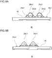
- Fig. 8A is a side view of the optical member illustrated in Fig. 5 , as viewed in the direction of C; and
- Fig. 8B is a side view of the optical member illustrated in Fig. 5 , as viewed in the direction of D.
- the up, down, front, and back directions indicated in Fig. 5 are defined with the direction of the optical axis Ax of the vehicle headlamp 10 regarded as the front direction.
- An optical member 40 includes a condenser lens 24 and a plate-like base portion 42.
- the condenser lens 24 serves as an optical controller that controls the light that enters the optical member 40 via a back side 24a to cause the light to exit via a front side 24b.
- the base portion 42 is adjacent to the condenser lens 24.
- the condenser lens 24 includes eight lens portions 24c1 corresponding to the respective lights emitted from the eight LEDs 20a1 and two lens portions 24c2 corresponding to the respective lights emitted from the two LEDs 20a2.
- to control light means to direct the light in a desired pattern, direction, or region, for example.
- the gap between the light emitting surface of the LEDs 20a and the entry surface of the condenser lens 24 according to the present embodiment is about 0.2 mm to about 1 mm or preferably about 0.2 mm to about 0.5 mm.
- the thickness of the base portion 42 is about 1 mm to about 5 mm or preferably about 2 mm to about 3 mm.
- the diameter of each dome-shaped lens portion 24c2 is about 2 mm to about 4 mm.
- the lens portions 24c1 and 24c2 of the optical member 40 are each shaped to condense the light transmitted therethrough by refracting the light.
- the lens portions 24c1 are each convex at its back side 24a as well as at its front side 24b.
- the lens portions 24c2 each include an expanding lens portion 24c3, which will be described later.
- a surface region of the front side 24b through which the light emitted from the LEDs 20a is transmitted to exit the optical controller functions as a light emitting surface of a pseudo-light source.
- the optical member 40 is an injection-molded component formed of a transparent material and can be formed of, for example but not limited to, heat-resistant silicone, acryl, polycarbonate, or glass.
- heat-resistant silicone can resist the heat of 180°C or higher
- glass is used, from the standpoint of its heat-resistant property.
- heat-resistant silicone is more preferable as it can be forcibly removed from a mold relatively easily.
- the optical member can be manufactured with a simple mold configuration or through a simple manufacturing method.
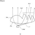
- Fig. 9 is a sectional view of the optical member illustrated in Fig. 5 , taken along the E-E line.
- the optical unit 18 includes the first light source 20, the optical member 40, and the convex lens 26.
- the plurality of LEDs 20a1 and 20a2 are disposed in an array in the first light source 20.
- the optical member 40 includes the plurality of lens portions 24c1 and 24c2 corresponding to the respective LEDs 20a1 and 20a2 and condenses the light emitted from the first light source 20.
- the convex lens 26 projects the light transmitted through the optical member 40 into the light illuminating direction of the optical unit to form a light distribution pattern.
- At least one of the plurality of lenses included in the optical member 40 includes the condensing lens portion 24c2 and the expanding lens portion 24c3.
- the condensing lens portion 24c2 is located in front of the light emitting surface of the corresponding LED 20a2.
- the expanding lens portion 24c3 receives light L1' emitted diagonally from the light emitting surface of the corresponding LED 20a2 and causes the light L1' to travel in the front direction of the lens so as to expand a luminous region of the lens.
- the expanding lens portion 24c3 is formed into a Fresnel lens. This configuration can help reduce the thickness of the expanding lens portion 24c3.
- the expanding lens portion 24c3 formed into a Fresnel lens has a longitudinal dimension of 3 mm to 5 mm and a lateral dimension of 3 mm to 5 mm as viewed from the front and has a height of about 3 mm to about 5 mm as viewed from the side.
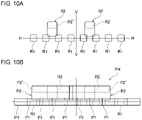
- Fig. 10A is a schematic diagram illustrating an illumination range obtained when a luminous region of a first light source according to the present embodiment is reflected and projected by a stationary rotary reflector; and Fig. 10B is a schematic diagram of a light distribution pattern formed by an optical unit.
- the surfaces of the eight lens portions 24c1 and the two lens portions 24c2 of the condenser lens 24 serve as a luminous region. Then, the surface of the stationary rotary reflector 22 reflects an image of the luminous region, and this image is projected into a space in front of the vehicle via the convex lens 26 (see Fig. 10A ).
- the eight lights that have exited the condenser lens 24 via the respective lens portions 24c1 form eight rectangular illumination regions R1 on the H-H line.
- the two lights that have exited the condenser lens 24 via the respective lens portions 24c2 and the respective expanding lens portions 24c3 form two rectangular illumination regions R2 on the upper side of the illumination regions R1.
- the expanding lens portions 24c3 expand the luminous region of the lens portions 24c2 in the vertical direction, and therefore the illumination regions R2 are each a rectangular region that is longer in the vertical direction.
- the condenser lens 24 includes only the lens portions 24c2, the light can illuminate only a range of up to about +4 degrees in the vertical direction on the screen in front of the vehicle.
- the condenser lens 24 that includes the expanding lens portions 24c3 the light can illuminate a range of up to about +6 degrees in the vertical direction on the screen in front of the vehicle.
- the optical unit 18 can expand the illumination region since the luminous region of the lens portions 24c2 is expanded in the vertical direction by the expanding lens portions 24c3.
- a high-beam light distribution pattern PH is formed as the partial light distribution patterns P1 and P2 are superposed on each other.
- the rotary reflector 22 forms a part or the whole of the high-beam light distribution pattern PH by reflecting and scanning the pattern of the luminous region of the condenser lens 24.
- the optical unit 18 forms upper regions P2' of the high-beam light distribution pattern PH by reflecting and scanning the patterns of the portions (regions R2'), of the luminous region of the condenser lens 24, that correspond to the expanding lens portions 24c3. This makes it possible to further expand the illumination region of the high-beam light distribution pattern PH in the vertical direction.
- the optical member 40 is disposed such that a virtual image of the luminous region of the condenser lens 24 formed by the rotary reflector 22 is located at or around the focal point of the convex lens 26.
- the optical member 40 may be disposed such that the luminous region of the condenser lens 24 is located at or around the focal point of the convex lens 26. This configuration allows the luminous region of the condenser lens 24 to be projected as a light source into the front direction of the convex lens 26.
- Fig. 11A is a top view of the condenser lens 24
- Fig. 11B is a schematic diagram illustrating a light distribution pattern obtained when a luminous region of the condenser lens 24 is reflected and projected by a stationary rotary reflector
- Fig. 11C is a schematic diagram of a light distribution pattern formed by an optical unit that includes the condenser lens 24.
- the condenser lens 24 includes an expanding lens portion 24c3 that receives light L1' emitted diagonally from the light emitting surface of the corresponding LED 20a2 and causes the light L1' to travel in the front direction of the lens so as to expand the luminous region of the lens.
- this expanding lens portions 24c3 includes three light controlling surfaces formed into Fresnel lenses in order to reduce the thickness of the lens itself. Therefore, the exit surface of the expanding lens portion 24c3 is uneven, and there is a clear border between adjacent light controlling surfaces.
- a dim portion (optical unevenness) continuing from one end to the other end of an image is produced in a part of the image of the luminous region of the condenser lens 24.
- a streaked dim portion is produced also in the light distribution pattern obtained by scanning the image of the luminous region illustrated in Fig. 11B . Accordingly, further improvement is necessary from the standpoint of achieving a high-quality light distribution pattern.
- Fig. 12A is a top view of a condenser lens 50 according to one example
- Fig. 12B is a schematic diagram illustrating a light distribution pattern obtained when a luminous region of the condenser lens 50 is reflected and projected by a stationary rotary reflector
- Fig. 12C is a schematic diagram of a light distribution pattern formed by an optical unit that includes the condenser lens 50.
- the condenser lens 50 includes an exit surface 52 divided into a plurality of light controlling surfaces.
- the exit surface 52 includes a first exit region 54 and a second exit region 56.
- the first exit region 54 includes a plurality of first light controlling surfaces 54a arrayed in a predetermined direction X.
- the second exit region 56 is located side by side with the first exit region 54 and includes a plurality of second light controlling surfaces 56a arrayed in the predetermined direction X.
- a border B1 between adjacent first light controlling surfaces 54a and a border B2 between adjacent second light controlling surfaces 56a are out of alignment in the predetermined direction X.
- a border B1 between adjacent first light controlling surfaces 54a and a border B2 between adjacent second light controlling surfaces 56a are not aligned either continuously or linearly. Accordingly, even if a dim portion (optical unevenness) is produced in an image of the luminous region as illustrated in Fig. 12B due to the shape of a border between adjacent light controlling surfaces (in particular, a discontinuous shape), no one dim portion traverses continuously from one end to the other end of the image.
- a vehicle headlamp 10 may include LEDs 20a, a condenser lens 50 that receives light emitted from the LEDs 20a, and a rotary reflector 22 that rotates about an axis of rotation while reflecting light transmitted through the condenser lens 50.
- the rotary reflector 22 reflects and scans luminous patterns of the first exit region 54 and the second exit region 56 to form at least a portion of a light distribution pattern. With this configuration, any streaked dim portion that may appear in a light distribution pattern (see Fig. 11C ) can be reduced, as illustrated in Fig. 12C .
- the rotary reflector 22 is preferably configured to scan a luminous pattern in a direction Y intersecting the predetermined direction X in which the first light controlling surfaces 54a and the second light controlling surfaces 56a illustrated in Fig. 12A are arrayed.
- At least one of the plurality of light controlling surfaces is a dome-shaped third light controlling surface 58 located in front of the light emitting surface of a corresponding LED 20a, and the third light controlling surface 58 is adjacent to both one of the first light controlling surfaces 54a and one of the second light controlling surfaces 56a.
- This configuration can make unevenness in a light distribution pattern less noticeable even when the first light controlling surfaces 54a and/or the second light controlling surfaces 56a, aside from the third light controlling surface 58 located in front of the light emitting surface of an LED 20a, are provided to expand the illumination region.
- the first light controlling surfaces 54a and the second light controlling surfaces 56a are configured to expand the luminous region of a lens by directing the light emitted diagonally from the light emitting surface to enter the lens and causing the light to exit toward the front.
- This configuration can make unevenness in a light distribution pattern less noticeable even when the first light controlling surfaces 54a and/or the second light controlling surfaces 56a having discontinuous concavities and convexities formed in their surfaces are provided to expand the illumination region.
- the present invention has been described with reference to the foregoing embodiments.
- the present invention is not limited to the foregoing embodiments and also encompasses an embodiment obtained by combining or replacing configurations of the foregoing embodiments, as appropriate.
- the rotary reflector 22 that includes the blades 22a is used in the foregoing embodiments.
- a polygon mirror instead of the rotary reflector 22, may be used.
- a micro-electromechanical system (MEMS) mirror (resonance mirror) instead of the rotary reflector 22, may be used.
- MEMS micro-electromechanical system
- a digital micromirror device instead of the rotary reflector 22, a digital micromirror device (DMD) in which a number of movable micromirrors are arrayed in a matrix may be used.
- a combination of a light source including a plurality of light emitting elements and an optical member including a plurality of first lenses has been described.
- a light source including one light emitting element and an optical member including one first lens may be combined.
- the luminous region of the first lens can be expanded by the expanding lens portions 24c3, and thus the illumination region of the light distribution pattern can be expanded.
- the present invention can find its use in vehicle lamps.
- B1, B2 border 10 vehicle headlamp, 18 optical unit, 20 first light source, 20a LED, 22 rotary reflector, 24 condenser lens, 25 front of lamp, 26 convex lens, 28 second light source, 28a LED, 30 diffuser lens, 33 circuit board, 40 optical member, 50 condenser lens, 52 exit surface, 54 first exit region, 54a first light controlling surface, 56 second exit region, 56a second light controlling surface, 58 third light controlling surface
Landscapes
- Engineering & Computer Science (AREA)
- General Engineering & Computer Science (AREA)
- Physics & Mathematics (AREA)
- Optics & Photonics (AREA)
- Microelectronics & Electronic Packaging (AREA)
- General Physics & Mathematics (AREA)
- Non-Portable Lighting Devices Or Systems Thereof (AREA)
Applications Claiming Priority (2)
| Application Number | Priority Date | Filing Date | Title |
|---|---|---|---|
| JP2019153852 | 2019-08-26 | ||
| PCT/JP2020/031646 WO2021039634A1 (ja) | 2019-08-26 | 2020-08-21 | レンズおよび灯具 |
Publications (2)
| Publication Number | Publication Date |
|---|---|
| EP4023936A1 true EP4023936A1 (de) | 2022-07-06 |
| EP4023936A4 EP4023936A4 (de) | 2022-10-05 |
Family
ID=74685558
Family Applications (1)
| Application Number | Title | Priority Date | Filing Date |
|---|---|---|---|
| EP20858402.9A Withdrawn EP4023936A4 (de) | 2019-08-26 | 2020-08-21 | Linse und beleuchtungswerkzeug |
Country Status (5)
| Country | Link |
|---|---|
| US (1) | US11774067B2 (de) |
| EP (1) | EP4023936A4 (de) |
| JP (1) | JP7357064B2 (de) |
| CN (1) | CN112432137B (de) |
| WO (1) | WO2021039634A1 (de) |
Family Cites Families (17)
| Publication number | Priority date | Publication date | Assignee | Title |
|---|---|---|---|---|
| JPH0317362Y2 (de) * | 1986-07-10 | 1991-04-12 | ||
| JP2006210294A (ja) * | 2005-01-31 | 2006-08-10 | Ichikoh Ind Ltd | 車両用灯具および車両用前照灯装置 |
| US20080247188A1 (en) * | 2007-04-04 | 2008-10-09 | Magna International Inc. | Complex projector lens for LED headlamp |
| JP4964753B2 (ja) * | 2007-12-12 | 2012-07-04 | 株式会社小糸製作所 | 車両用照明灯具 |
| CN102947745A (zh) * | 2009-08-20 | 2013-02-27 | 光处方革新有限公司 | 步阶式流线聚光器和准直器 |
| CN102844616B (zh) * | 2010-04-13 | 2015-06-10 | 株式会社小糸制作所 | 光学单元、车辆监视装置及障碍物检测装置 |
| JP2014082164A (ja) * | 2012-10-18 | 2014-05-08 | Ichikoh Ind Ltd | 車両用灯具 |
| JP6201708B2 (ja) * | 2013-12-11 | 2017-09-27 | スタンレー電気株式会社 | 車両用灯具及びレンズ体 |
| CN104100909B (zh) * | 2014-08-04 | 2016-01-27 | 安徽师范大学 | 一种基于复眼透镜的自适应前照灯设计方法 |
| JP6951076B2 (ja) * | 2016-10-14 | 2021-10-20 | 株式会社小糸製作所 | 光学ユニット |
| US10180222B2 (en) | 2016-10-14 | 2019-01-15 | Koito Manufacturing Co., Ltd. | Optical unit |
| WO2018166911A1 (en) * | 2017-03-17 | 2018-09-20 | Lumileds Holding B.V. | Multi-focal collimating lens and headlight assembly for an automotive low beam |
| WO2018212010A1 (ja) * | 2017-05-17 | 2018-11-22 | 株式会社小糸製作所 | 光学ユニット |
| KR20190081690A (ko) * | 2017-12-29 | 2019-07-09 | 에스엘 주식회사 | 차량용 램프 |
| US11486557B2 (en) * | 2018-10-19 | 2022-11-01 | Koito Manufacturing Co., Ltd. | Vehicle lamp, lamp unit, and reflector module |
| CN116677952A (zh) * | 2018-12-25 | 2023-09-01 | 株式会社小糸制作所 | 光学单元 |
| TWM579699U (zh) * | 2018-12-28 | 2019-06-21 | 大陸商揚州雷笛克光學有限公司 | 導光透鏡及交通工具頭燈 |
-
2020
- 2020-08-19 CN CN202010836021.2A patent/CN112432137B/zh active Active
- 2020-08-21 JP JP2021542842A patent/JP7357064B2/ja active Active
- 2020-08-21 EP EP20858402.9A patent/EP4023936A4/de not_active Withdrawn
- 2020-08-21 WO PCT/JP2020/031646 patent/WO2021039634A1/ja not_active Ceased
-
2022
- 2022-02-11 US US17/669,735 patent/US11774067B2/en active Active
Also Published As
| Publication number | Publication date |
|---|---|
| CN112432137B (zh) | 2022-11-15 |
| JP7357064B2 (ja) | 2023-10-05 |
| US20220163189A1 (en) | 2022-05-26 |
| JPWO2021039634A1 (de) | 2021-03-04 |
| US11774067B2 (en) | 2023-10-03 |
| CN112432137A (zh) | 2021-03-02 |
| EP4023936A4 (de) | 2022-10-05 |
| WO2021039634A1 (ja) | 2021-03-04 |
Similar Documents
| Publication | Publication Date | Title |
|---|---|---|
| US11573000B2 (en) | Optical unit | |
| US10794559B2 (en) | Vehicle lamp and vehicle having the same | |
| EP2112425B1 (de) | Streulichtprojektor | |
| CN108375029B (zh) | 光学单元 | |
| CN103597276B (zh) | 光学单元 | |
| JP7002046B2 (ja) | 車両用前照灯 | |
| CN209558250U (zh) | 车辆用灯具 | |
| JP2023101669A (ja) | 光学ユニット | |
| JP2024099853A (ja) | 光学ユニットおよび反射面決定方法 | |
| JP6432902B2 (ja) | 灯具ユニット | |
| US11774067B2 (en) | Lens and lamp | |
| JP5193546B2 (ja) | 車両用灯具 | |
| WO2020080134A1 (ja) | 車両用灯具および回転リフレクタ | |
| EP3812652B1 (de) | Fahrzeuglampe | |
| CN210860951U (zh) | 车辆用灯具 | |
| JP6872417B2 (ja) | 光学ユニット | |
| JP7545405B2 (ja) | 灯具ユニット | |
| EP1054210A2 (de) | Scheinwerfer nach dem Projektionstyp für Kraftfahrzeuge | |
| CN118843765A (zh) | 车辆用灯具 |
Legal Events
| Date | Code | Title | Description |
|---|---|---|---|
| STAA | Information on the status of an ep patent application or granted ep patent |
Free format text: STATUS: THE INTERNATIONAL PUBLICATION HAS BEEN MADE |
|
| PUAI | Public reference made under article 153(3) epc to a published international application that has entered the european phase |
Free format text: ORIGINAL CODE: 0009012 |
|
| STAA | Information on the status of an ep patent application or granted ep patent |
Free format text: STATUS: REQUEST FOR EXAMINATION WAS MADE |
|
| 17P | Request for examination filed |
Effective date: 20220216 |
|
| AK | Designated contracting states |
Kind code of ref document: A1 Designated state(s): AL AT BE BG CH CY CZ DE DK EE ES FI FR GB GR HR HU IE IS IT LI LT LU LV MC MK MT NL NO PL PT RO RS SE SI SK SM TR |
|
| REG | Reference to a national code |
Ref country code: DE Ref legal event code: R079 Free format text: PREVIOUS MAIN CLASS: F21S0041265000 Ipc: F21S0041200000 |
|
| A4 | Supplementary search report drawn up and despatched |
Effective date: 20220906 |
|
| RIC1 | Information provided on ipc code assigned before grant |
Ipc: F21W 102/145 20180101ALI20220831BHEP Ipc: G02B 3/08 20060101ALI20220831BHEP Ipc: F21S 41/675 20180101ALI20220831BHEP Ipc: F21S 41/151 20180101ALI20220831BHEP Ipc: F21S 41/148 20180101ALI20220831BHEP Ipc: F21S 41/20 20180101AFI20220831BHEP |
|
| DAV | Request for validation of the european patent (deleted) | ||
| DAX | Request for extension of the european patent (deleted) | ||
| 18W | Application withdrawn |
Effective date: 20240618 |