EP4023837B1 - Rainwater trap trapping the water from a gutter system - Google Patents
Rainwater trap trapping the water from a gutter system Download PDFInfo
- Publication number
- EP4023837B1 EP4023837B1 EP21217513.7A EP21217513A EP4023837B1 EP 4023837 B1 EP4023837 B1 EP 4023837B1 EP 21217513 A EP21217513 A EP 21217513A EP 4023837 B1 EP4023837 B1 EP 4023837B1
- Authority
- EP
- European Patent Office
- Prior art keywords
- sealing
- partition
- rainwater
- pipe
- fixing agent
- Prior art date
- Legal status (The legal status is an assumption and is not a legal conclusion. Google has not performed a legal analysis and makes no representation as to the accuracy of the status listed.)
- Active
Links
Images


Classifications
-
- E—FIXED CONSTRUCTIONS
- E04—BUILDING
- E04D—ROOF COVERINGS; SKY-LIGHTS; GUTTERS; ROOF-WORKING TOOLS
- E04D13/00—Special arrangements or devices in connection with roof coverings; Protection against birds; Roof drainage ; Sky-lights
- E04D13/04—Roof drainage; Drainage fittings in flat roofs, balconies or the like
- E04D13/08—Down pipes; Special clamping means therefor
-
- E—FIXED CONSTRUCTIONS
- E03—WATER SUPPLY; SEWERAGE
- E03B—INSTALLATIONS OR METHODS FOR OBTAINING, COLLECTING, OR DISTRIBUTING WATER
- E03B1/00—Methods or layout of installations for water supply
- E03B1/04—Methods or layout of installations for water supply for domestic or like local supply
- E03B1/041—Greywater supply systems
- E03B2001/047—Greywater supply systems using rainwater
-
- E—FIXED CONSTRUCTIONS
- E04—BUILDING
- E04D—ROOF COVERINGS; SKY-LIGHTS; GUTTERS; ROOF-WORKING TOOLS
- E04D13/00—Special arrangements or devices in connection with roof coverings; Protection against birds; Roof drainage ; Sky-lights
- E04D13/04—Roof drainage; Drainage fittings in flat roofs, balconies or the like
- E04D13/08—Down pipes; Special clamping means therefor
- E04D2013/0806—Details of lower end of down pipes, e.g. connection to water disposal system
- E04D2013/0813—Water diverters
Definitions
- the subject of the invention is a rainwater trap trapping the water from the gutter system, enabling the collection of rainwater flowing from the roofs of buildings, intended for filling tanks located above the foundation level of the facilities.
- the solution is aimed at efficient collection of rainwater and the use of such collected water for irrigation, e.g. in gardens located next to the facilities, which significantly affects water saving.
- the collected water can also be used for other household and industrial purposes.
- the trapping of part of the water and its collection in any place during intense rainfall relieves the rainwater sewage system, reducing the risk of partial inundation or flooding.
- the solutions for trapping the rainwater from gutter systems available on the market are limited to trapping rainwater from the rainwater outlet of the gutter by placing a tank and storing it at a level slightly above the ground.
- Other known solutions consist in incorporating, during the construction of the gutter system, a short section of the pipe with an internal ring that catches water and directs it outside the downpipe. The use of this method is limited to the implementation of the solution during the construction of the gutter system and gutter system is usually built at the stage of building construction or renovation works.
- the aim of the invention is to provide a simple, cheap, cost-effective and reliable solution that allows rainwater to be stored and used, inter alia, for irrigation of adjacent gardens, for household purposes, and for any other application, e.g. during periods of absence of owner, and, what is important, without the participation of other energy sources, such as an electric pump.
- the rainwater trap trapping the water from the gutter system comprises the features of claim 1.
- It comprises an overflow stub pipe, inside which a water pipe is placed, and a partition and a pipe for supplying the sealing and fixing agent to the partition are attached to the outer (side) wall of the overflow stub pipe.
- the partition is a semi-permeable mesh filled with a sealing and fixing agent.
- the partition is a rubber torus-tube filled with a sealing and fixing agent.
- the sealing and fixing agent introduced into the partition by means of the pipe for supplying the sealing and fixing agent is any hardening foam, preferably a polyurethane foam.
- the sealing and fixing agent introduced into the partition by means of the pipe for supplying the sealing and fixing agent is any agent enabling filling the partition up to the pre-set pressure.
- the sealing and fixing agent is any gas unaggressive to the rainwater trap materials, for example air, carbon dioxide, argon.
- the sealing and fixing agent is any liquid unaggressive to the rainwater trap materials, for example water.
- the partition fixes the rainwater trap in the gutter system after the sealing and fixing agent has been introduced by means of the pipe for supplying the sealing and fixing agent, after reaching the planned location in the downpipe.
- the rainwater trap from the gutter system is installed in a permanent or multiple version, i.e. with the possibility of being dismantled at any time.
- the overflow stub pipe, the water pipe, the partition and the pipe supplying the sealing and fixing agent to the partition are integrated in such way that they constitute one monolith.
- the rainwater trap trapping the water from the gutter system according to the invention can be used at any time of the existence of the gutter system as well as during the construction of the gutter system. It is important because the solution according to the invention can be applied to any facility, to any existing downpipe. It is therefore possible to use this solution on a mass scale without the use of scaffolding or even any tools.
- the number of buildings under construction is about 1 percent compared to the existing ones, which results in low efficiency of solutions that are used only during construction. Thanks to the solution according to the invention intended for existing buildings, it is possible to solve the problem of collecting of the rainwater from all roofs in a short time. This problem is becoming more and more pressing for the present day.
- the shortcomings of the existing solutions include the need to laboriously incorporate additional devices into the gutter system already at the construction stage of the building or the rather difficult assembly in existing buildings, including the use of additional scaffolding.
- Fig. 1 shows a vertical section of the gutter system rainwater trap
- Fig. 2 shows a vertical section of the gutter system rainwater trap after placing it in downpipe
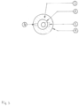
- Fig. 3 is a horizontal cross-section of the gutter system rainwater trap placed in the downpipe
- Fig. 4 shows an illustrative application of the solution according to the invention.
- the partition 3 is realized by placing a set of elements 1, 2, 3, 4 in the vertical downpipe 5, and after placing at the target level in the vertical downpipe 5, the partition is filled by applying a sealing and fixing agent.
- the gutter system rainwater trap comprises an overflow stub pipe 1, inside which a water pipe 2 is placed, while to the outer (side) wall of the overflow stub pipe 1 there is attached a partition 3 and a pipe 4 for supplying sealing and fixing agent to the partition 3.
- the partition 3 is made of a torus-tube-shaped rubber and is applied to the downpipe 5 in a flaccid form ( Fig. 1 ). After reaching the position at the set height of the downpipe 5 ( Fig. 2 ), the gutter system rainwater trap is brought to the target state by inflating air to the set pressure by means of pipe 4 for supplying the sealing-fixing agent and the invention is maintained in the inflated state throughout the entire operating time ( Fig. 2 ).
- the sealing and fixing agent may be any fluid unaggressive to the particular material parts of the rainwater trap, for example unaggressive gas (air, nitrogen, argon, carbon dioxide) or liquid (for example water).
- unaggressive gas air, nitrogen, argon, carbon dioxide
- liquid for example water.
- the torus-tube-shaped partition 3 After fulfilling its role, after deflating the air or other sealing and fixing agent, the torus-tube-shaped partition 3 returns to its initial state in a flaccid form ( Fig. 1 ) and the trap according to the invention can be withdrawn from the downpipe 5. Filling and draining of the sealing and fixing agent can be repeated many times.
- the invention traps the rainwater from the gutter downpipe 5 at any height between the rainwater inlet to the gutter downpipe 5 and the outlet, thereby allowing rainwater to be collected (e.g.
- the gutter system rainwater trap allows to store (collect) rainwater at a significant height, including the level chosen by installing the solution according to the invention. Water will be collected in a tank, on the basis of communicating vessels at the level of the gutter system in the downpipe 5. The only interference with the existing gutter system consists in placing the solution according to the invention there, and only the semi-rigid water pipe 2 will be visible coming from the outlet of the gutter downpipe or from the inspection hole.
- the person skilled in the art would appreciate that the possibility of easy dismounting of the water trap is convenient for maintaining the installation clean and in good general condition. For example, the rainwater may be dismounted in order to remove the leaves covering the gutter or dismounted for the time of winter and mounted again in spring.
- Another alternative embodiment of the invention is the possibility of fixing the gutter system rainwater trap in the vertical downpipe 5 in such way that the partition 3 is made of a semi-permeable mesh.
- a bag is formed with dimensions adapted to the downpipe 5 and the overflow connector 1.
- the partition 3 is filled with hardening foam, thus creating a partition 3.
- the gutter system rainwater trap is ready to fulfil its task of damming and directing the rainwater to the water pipe 2 and then to the water tank 6 or elsewhere at the level of the partition 3 or below.
- the hardening foam may be any hardening foam, for example polyurethane foam, such as one known commercially, of Soudal company or other.
- the advantage of using the invention is that by trapping and collecting rainwater, this water can be used both during rainfall and after the rainfall has stopped, at any time, by using the accumulated water from the water tank 6.
- Water accumulated at a height of several or a dozen meters above the ground can be used without an additional pump, by gravity flow, for watering, for example, a home garden.
- the trap according to the invention will catch any, even small amounts of water, because a tight partition 3 of the downpipe 5 is used.
Landscapes
- Engineering & Computer Science (AREA)
- Architecture (AREA)
- Civil Engineering (AREA)
- Structural Engineering (AREA)
- Sewage (AREA)
- Building Awnings And Sunshades (AREA)
- Other Liquid Machine Or Engine Such As Wave Power Use (AREA)
Applications Claiming Priority (1)
| Application Number | Priority Date | Filing Date | Title |
|---|---|---|---|
| PL436608A PL436608A1 (pl) | 2020-12-31 | 2020-12-31 | Wychwytywacz wody opadowej z instalacji rynnowej |
Publications (3)
| Publication Number | Publication Date |
|---|---|
| EP4023837A1 EP4023837A1 (en) | 2022-07-06 |
| EP4023837B1 true EP4023837B1 (en) | 2024-09-25 |
| EP4023837C0 EP4023837C0 (en) | 2024-09-25 |
Family
ID=80446909
Family Applications (1)
| Application Number | Title | Priority Date | Filing Date |
|---|---|---|---|
| EP21217513.7A Active EP4023837B1 (en) | 2020-12-31 | 2021-12-23 | Rainwater trap trapping the water from a gutter system |
Country Status (2)
| Country | Link |
|---|---|
| EP (1) | EP4023837B1 (pl) |
| PL (2) | PL436608A1 (pl) |
Families Citing this family (1)
| Publication number | Priority date | Publication date | Assignee | Title |
|---|---|---|---|---|
| CN116464174B (zh) * | 2023-04-14 | 2025-05-09 | 广州市盾建建设有限公司 | 幕墙飘带雨水导流装置 |
Family Cites Families (3)
| Publication number | Priority date | Publication date | Assignee | Title |
|---|---|---|---|---|
| GB2500418B (en) * | 2012-03-21 | 2014-09-10 | Christopher Douglas Blair | Apparatus for the collection of rainwater from a downpipe |
| CN204551589U (zh) * | 2015-03-27 | 2015-08-12 | 刘冰冰 | 基于雨落管截流器的屋面环保集雨系统 |
| ITUB20155918A1 (it) * | 2015-11-06 | 2017-05-06 | Romolo Baroni | Dispositivo pneumatico di raccolta delle acque piovane da introdurre in un foro circolare praticato nel pluviale. |
-
2020
- 2020-12-31 PL PL436608A patent/PL436608A1/pl unknown
-
2021
- 2021-12-23 PL PL21217513.7T patent/PL4023837T3/pl unknown
- 2021-12-23 EP EP21217513.7A patent/EP4023837B1/en active Active
Also Published As
| Publication number | Publication date |
|---|---|
| PL436608A1 (pl) | 2022-07-04 |
| EP4023837C0 (en) | 2024-09-25 |
| PL4023837T3 (pl) | 2025-02-10 |
| EP4023837A1 (en) | 2022-07-06 |
Similar Documents
| Publication | Publication Date | Title |
|---|---|---|
| US20090279954A1 (en) | Debris and sediment reduction apparatus for water drainage systems | |
| KR101703337B1 (ko) | 초기 빗물 배제 및 여과장치 | |
| WO2013045673A1 (en) | A rainwater collection and distribution device | |
| KR100978230B1 (ko) | 조립식 우수 여과장치 | |
| US10653983B2 (en) | Connector pipe screen | |
| EP4023837B1 (en) | Rainwater trap trapping the water from a gutter system | |
| KR101574644B1 (ko) | 이물질이 함유된 초기빗물을 배제한 우수 집수장치 | |
| US6739800B2 (en) | Self-flushing gutter pipe | |
| KR20110055848A (ko) | 프리캐스트 콘크리트 저수조의 구조 | |
| DE102010011236A1 (de) | Regenwassergewinnungsanlage mit geometrisch geformten Speicherelementen | |
| KR20130011103A (ko) | 빗물관리시설장치 | |
| EP3653799A1 (en) | Fog collector or device for collecting the water present in the atmosphere | |
| KR200464340Y1 (ko) | 빗물 이용시설 | |
| KR101327197B1 (ko) | 빗물 여과장치 및 그것이 구비된 빗물 저류탱크 | |
| JP2005330776A (ja) | 雨水貯留装置及び該雨水貯留装置を用いた雨水貯留システム | |
| GB2314367A (en) | Rainwater collection and dispersal system | |
| RU163974U1 (ru) | Узел аварийного сброса воды в системе ливневой канализации | |
| CN216380294U (zh) | 用于屋顶檐口排水的铝板结构 | |
| CN217460753U (zh) | 一种建筑物雨水收集系统 | |
| JP2001173027A (ja) | 貯水槽および給水システム | |
| CN219080473U (zh) | 壁挂式雨水收集装置 | |
| KR20090009514A (ko) | 빗물배수용 수직 홈통의 이물질여과장치 | |
| CN215715704U (zh) | 屋面雨水收集利用装置 | |
| CN223523353U (zh) | 露台花园用防雨水倒灌结构 | |
| CN222001139U (zh) | 坑道排水系统 |
Legal Events
| Date | Code | Title | Description |
|---|---|---|---|
| PUAI | Public reference made under article 153(3) epc to a published international application that has entered the european phase |
Free format text: ORIGINAL CODE: 0009012 |
|
| STAA | Information on the status of an ep patent application or granted ep patent |
Free format text: STATUS: REQUEST FOR EXAMINATION WAS MADE |
|
| 17P | Request for examination filed |
Effective date: 20220111 |
|
| AK | Designated contracting states |
Kind code of ref document: A1 Designated state(s): AL AT BE BG CH CY CZ DE DK EE ES FI FR GB GR HR HU IE IS IT LI LT LU LV MC MK MT NL NO PL PT RO RS SE SI SK SM TR |
|
| GRAP | Despatch of communication of intention to grant a patent |
Free format text: ORIGINAL CODE: EPIDOSNIGR1 |
|
| STAA | Information on the status of an ep patent application or granted ep patent |
Free format text: STATUS: GRANT OF PATENT IS INTENDED |
|
| INTG | Intention to grant announced |
Effective date: 20240429 |
|
| GRAS | Grant fee paid |
Free format text: ORIGINAL CODE: EPIDOSNIGR3 |
|
| GRAA | (expected) grant |
Free format text: ORIGINAL CODE: 0009210 |
|
| STAA | Information on the status of an ep patent application or granted ep patent |
Free format text: STATUS: THE PATENT HAS BEEN GRANTED |
|
| AK | Designated contracting states |
Kind code of ref document: B1 Designated state(s): AL AT BE BG CH CY CZ DE DK EE ES FI FR GB GR HR HU IE IS IT LI LT LU LV MC MK MT NL NO PL PT RO RS SE SI SK SM TR |
|
| REG | Reference to a national code |
Ref country code: GB Ref legal event code: FG4D |
|
| REG | Reference to a national code |
Ref country code: CH Ref legal event code: EP |
|
| REG | Reference to a national code |
Ref country code: DE Ref legal event code: R096 Ref document number: 602021019264 Country of ref document: DE |
|
| REG | Reference to a national code |
Ref country code: IE Ref legal event code: FG4D |
|
| U01 | Request for unitary effect filed |
Effective date: 20241015 |
|
| U07 | Unitary effect registered |
Designated state(s): AT BE BG DE DK EE FI FR IT LT LU LV MT NL PT RO SE SI Effective date: 20241031 |
|
| U20 | Renewal fee for the european patent with unitary effect paid |
Year of fee payment: 4 Effective date: 20241108 |
|
| PG25 | Lapsed in a contracting state [announced via postgrant information from national office to epo] |
Ref country code: NO Free format text: LAPSE BECAUSE OF FAILURE TO SUBMIT A TRANSLATION OF THE DESCRIPTION OR TO PAY THE FEE WITHIN THE PRESCRIBED TIME-LIMIT Effective date: 20241225 |
|
| PG25 | Lapsed in a contracting state [announced via postgrant information from national office to epo] |
Ref country code: GR Free format text: LAPSE BECAUSE OF FAILURE TO SUBMIT A TRANSLATION OF THE DESCRIPTION OR TO PAY THE FEE WITHIN THE PRESCRIBED TIME-LIMIT Effective date: 20241226 |
|
| PG25 | Lapsed in a contracting state [announced via postgrant information from national office to epo] |
Ref country code: RS Free format text: LAPSE BECAUSE OF FAILURE TO SUBMIT A TRANSLATION OF THE DESCRIPTION OR TO PAY THE FEE WITHIN THE PRESCRIBED TIME-LIMIT Effective date: 20241225 |
|
| PG25 | Lapsed in a contracting state [announced via postgrant information from national office to epo] |
Ref country code: RS Free format text: LAPSE BECAUSE OF FAILURE TO SUBMIT A TRANSLATION OF THE DESCRIPTION OR TO PAY THE FEE WITHIN THE PRESCRIBED TIME-LIMIT Effective date: 20241225 Ref country code: NO Free format text: LAPSE BECAUSE OF FAILURE TO SUBMIT A TRANSLATION OF THE DESCRIPTION OR TO PAY THE FEE WITHIN THE PRESCRIBED TIME-LIMIT Effective date: 20241225 Ref country code: GR Free format text: LAPSE BECAUSE OF FAILURE TO SUBMIT A TRANSLATION OF THE DESCRIPTION OR TO PAY THE FEE WITHIN THE PRESCRIBED TIME-LIMIT Effective date: 20241226 |
|
| PG25 | Lapsed in a contracting state [announced via postgrant information from national office to epo] |
Ref country code: IS Free format text: LAPSE BECAUSE OF FAILURE TO SUBMIT A TRANSLATION OF THE DESCRIPTION OR TO PAY THE FEE WITHIN THE PRESCRIBED TIME-LIMIT Effective date: 20250125 |
|
| PG25 | Lapsed in a contracting state [announced via postgrant information from national office to epo] |
Ref country code: SM Free format text: LAPSE BECAUSE OF FAILURE TO SUBMIT A TRANSLATION OF THE DESCRIPTION OR TO PAY THE FEE WITHIN THE PRESCRIBED TIME-LIMIT Effective date: 20240925 |
|
| PG25 | Lapsed in a contracting state [announced via postgrant information from national office to epo] |
Ref country code: ES Free format text: LAPSE BECAUSE OF FAILURE TO SUBMIT A TRANSLATION OF THE DESCRIPTION OR TO PAY THE FEE WITHIN THE PRESCRIBED TIME-LIMIT Effective date: 20240925 |
|
| PGFP | Annual fee paid to national office [announced via postgrant information from national office to epo] |
Ref country code: CH Payment date: 20250101 Year of fee payment: 4 |
|
| PG25 | Lapsed in a contracting state [announced via postgrant information from national office to epo] |
Ref country code: CZ Free format text: LAPSE BECAUSE OF FAILURE TO SUBMIT A TRANSLATION OF THE DESCRIPTION OR TO PAY THE FEE WITHIN THE PRESCRIBED TIME-LIMIT Effective date: 20240925 |
|
| PG25 | Lapsed in a contracting state [announced via postgrant information from national office to epo] |
Ref country code: SK Free format text: LAPSE BECAUSE OF FAILURE TO SUBMIT A TRANSLATION OF THE DESCRIPTION OR TO PAY THE FEE WITHIN THE PRESCRIBED TIME-LIMIT Effective date: 20240925 |
|
| PG25 | Lapsed in a contracting state [announced via postgrant information from national office to epo] |
Ref country code: MC Free format text: LAPSE BECAUSE OF FAILURE TO SUBMIT A TRANSLATION OF THE DESCRIPTION OR TO PAY THE FEE WITHIN THE PRESCRIBED TIME-LIMIT Effective date: 20240925 |
|
| PLBE | No opposition filed within time limit |
Free format text: ORIGINAL CODE: 0009261 |
|
| STAA | Information on the status of an ep patent application or granted ep patent |
Free format text: STATUS: NO OPPOSITION FILED WITHIN TIME LIMIT |
|
| 26N | No opposition filed |
Effective date: 20250626 |
|
| PGFP | Annual fee paid to national office [announced via postgrant information from national office to epo] |
Ref country code: PL Payment date: 20250929 Year of fee payment: 5 |
|
| PG25 | Lapsed in a contracting state [announced via postgrant information from national office to epo] |
Ref country code: IE Free format text: LAPSE BECAUSE OF NON-PAYMENT OF DUE FEES Effective date: 20241223 |
|
| PG25 | Lapsed in a contracting state [announced via postgrant information from national office to epo] |
Ref country code: HR Free format text: LAPSE BECAUSE OF FAILURE TO SUBMIT A TRANSLATION OF THE DESCRIPTION OR TO PAY THE FEE WITHIN THE PRESCRIBED TIME-LIMIT Effective date: 20240925 |
|
| REG | Reference to a national code |
Ref country code: CH Ref legal event code: U11 Free format text: ST27 STATUS EVENT CODE: U-0-0-U10-U11 (AS PROVIDED BY THE NATIONAL OFFICE) Effective date: 20260115 |
|
| U20 | Renewal fee for the european patent with unitary effect paid |
Year of fee payment: 5 Effective date: 20251230 |