EP4023805A1 - Controlling process air bypass around the drum in combo wash-dry system - Google Patents
Controlling process air bypass around the drum in combo wash-dry system Download PDFInfo
- Publication number
- EP4023805A1 EP4023805A1 EP21217210.0A EP21217210A EP4023805A1 EP 4023805 A1 EP4023805 A1 EP 4023805A1 EP 21217210 A EP21217210 A EP 21217210A EP 4023805 A1 EP4023805 A1 EP 4023805A1
- Authority
- EP
- European Patent Office
- Prior art keywords
- drum
- seal
- tub
- dryer machine
- combination washer
- Prior art date
- Legal status (The legal status is an assumption and is not a legal conclusion. Google has not performed a legal analysis and makes no representation as to the accuracy of the status listed.)
- Granted
Links
Images




Classifications
-
- D—TEXTILES; PAPER
- D06—TREATMENT OF TEXTILES OR THE LIKE; LAUNDERING; FLEXIBLE MATERIALS NOT OTHERWISE PROVIDED FOR
- D06F—LAUNDERING, DRYING, IRONING, PRESSING OR FOLDING TEXTILE ARTICLES
- D06F25/00—Washing machines with receptacles, e.g. perforated, having a rotary movement, e.g. oscillatory movement, the receptacle serving both for washing and for centrifugally separating water from the laundry and having further drying means, e.g. using hot air
-
- D—TEXTILES; PAPER
- D06—TREATMENT OF TEXTILES OR THE LIKE; LAUNDERING; FLEXIBLE MATERIALS NOT OTHERWISE PROVIDED FOR
- D06F—LAUNDERING, DRYING, IRONING, PRESSING OR FOLDING TEXTILE ARTICLES
- D06F37/00—Details specific to washing machines covered by groups D06F21/00 - D06F25/00
- D06F37/20—Mountings, e.g. resilient mountings, for the rotary receptacle, motor, tub or casing; Preventing or damping vibrations
- D06F37/22—Mountings, e.g. resilient mountings, for the rotary receptacle, motor, tub or casing; Preventing or damping vibrations in machines with a receptacle rotating or oscillating about a horizontal axis
-
- D—TEXTILES; PAPER
- D06—TREATMENT OF TEXTILES OR THE LIKE; LAUNDERING; FLEXIBLE MATERIALS NOT OTHERWISE PROVIDED FOR
- D06F—LAUNDERING, DRYING, IRONING, PRESSING OR FOLDING TEXTILE ARTICLES
- D06F37/00—Details specific to washing machines covered by groups D06F21/00 - D06F25/00
- D06F37/26—Casings; Tubs
- D06F37/266—Gaskets mounted between tub and casing around the loading opening
-
- D—TEXTILES; PAPER
- D06—TREATMENT OF TEXTILES OR THE LIKE; LAUNDERING; FLEXIBLE MATERIALS NOT OTHERWISE PROVIDED FOR
- D06F—LAUNDERING, DRYING, IRONING, PRESSING OR FOLDING TEXTILE ARTICLES
- D06F37/00—Details specific to washing machines covered by groups D06F21/00 - D06F25/00
- D06F37/26—Casings; Tubs
- D06F37/267—Tubs specially adapted for mounting thereto components or devices not provided for in preceding subgroups
-
- D—TEXTILES; PAPER
- D06—TREATMENT OF TEXTILES OR THE LIKE; LAUNDERING; FLEXIBLE MATERIALS NOT OTHERWISE PROVIDED FOR
- D06F—LAUNDERING, DRYING, IRONING, PRESSING OR FOLDING TEXTILE ARTICLES
- D06F37/00—Details specific to washing machines covered by groups D06F21/00 - D06F25/00
- D06F37/02—Rotary receptacles, e.g. drums
-
- D—TEXTILES; PAPER
- D06—TREATMENT OF TEXTILES OR THE LIKE; LAUNDERING; FLEXIBLE MATERIALS NOT OTHERWISE PROVIDED FOR
- D06F—LAUNDERING, DRYING, IRONING, PRESSING OR FOLDING TEXTILE ARTICLES
- D06F37/00—Details specific to washing machines covered by groups D06F21/00 - D06F25/00
- D06F37/02—Rotary receptacles, e.g. drums
- D06F37/04—Rotary receptacles, e.g. drums adapted for rotation or oscillation about a horizontal or inclined axis
-
- D—TEXTILES; PAPER
- D06—TREATMENT OF TEXTILES OR THE LIKE; LAUNDERING; FLEXIBLE MATERIALS NOT OTHERWISE PROVIDED FOR
- D06F—LAUNDERING, DRYING, IRONING, PRESSING OR FOLDING TEXTILE ARTICLES
- D06F58/00—Domestic laundry dryers
- D06F58/02—Domestic laundry dryers having dryer drums rotating about a horizontal axis
- D06F58/04—Details
Definitions
- the present disclosure relates to combination washer/dryer machines and, more particularly, to a combination washer/dryer machine with a seal sealing a gap formed between the drum and tub during washing and drying operations.
- a combination washer/dryer machine comprises a cabinet, a tub positioned inside the cabinet, and a drum that is rotatable inside the tub.
- the tub has an inner surface and the drum has an external surface.
- a seal is positioned between the exterior surface of the drum and the inner surface of the tub to form a seal gap between the seal and the drum or between the seal and the tub during both washing and drying operations.
- the seal is configured to provide a flow restriction through the seal gap that minimizes drying air from bypassing the drum during the drying operation.
- the tub has a cylindrical wall and an end wall
- the drum has a cylindrical sidewall and an end plate surface
- the seal is positioned between the end wall of the tub and the end plate surface of the drum.
- the seal includes a securement portion and a flap portion.
- the flap portion is dynamic and is manufactured from a material to enable the flap portion to deflect.
- the securement portion of the seal may be attached to the drum such that the seal rotation with the drum.
- the flap portion of the seal may be configured to move in response to the centrifugal force created by rotation (i.e., the RPM) of the drum.
- the flap portion of the seal may extend from the drum at a first height when the drum is in a non-rotating position and may be configured to deflect further from the drum during rotation of the drum.
- the combination washer/dryer machine comprises a cabinet, tub mounted inside the cabinet, and a drum that is rotatable within the tub.
- the drum has an external surface and tub has an inner surface.
- a seal extends between the exterior surface of the drum and the inner surface of the tub to form a seal gap between the seal and the drum or between the seal and the tub during both washing and drying operations.
- the seal is configured to provide a flow restriction through the seal gap that minimizes drying air from bypassing the drum during the drying operation.
- the seal includes a securement portion and a flap portion.
- the flap portion is dynamic, is manufactured from a material to enable the flap portion to deflect, and is configured to move in response to the air force created by the flow of drying air through and around the drum.
- the securement portion of the seal may be attached to either the drum or the tub.
- the tub has a ring that includes a plurality of apertures.
- the apertures in the ring are covered by seal during the washing operation and the seal is configured to move away from the ring during the drying operation to enable the drying air to pass through the apertures in the ring.
- the drying air passing through the apertures in the ring during the drying operation moves the seal towards the drum to reduce the seal gap.
- the combination washer/dryer machine comprises a cabinet, tub mounted inside the cabinet, and a drum that is rotatable within the tub.
- the drum has an external surface and tub has an inner surface.
- a seal extends between the exterior surface of the drum and the inner surface of the tub to form a seal gap between the seal and the drum or between the seal and the tub during both washing and drying operations.
- the seal is configured to provide a flow restriction through the seal gap that minimizes drying air from bypassing the drum during the drying operation.
- the seal may be attached to either the drum or the tub and includes a channel that directs airflow around the drum to provide a labyrinth shaped air flow path / seal.
- the seal includes a first step portion, a second step portion, and a third step portion, which cooperate to form the channel.
- the second step portion may have a smaller height than the first and third step portions and may be positioned adjacent to an edge of the drum, while the first and third step portion may each have a larger height such that they project closer to the drum and form the channel that provides for a labyrinth flow of air passing around the seal.
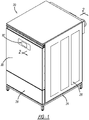
- the combination washer/dryer machine 20 includes a cabinet 24 with a plurality of panels 26.
- the front panel 28 includes a door 30 to enable access into the combination washer/dryer machine 20.
- Controls 32 are positioned on the front panel 28. The control controls the operation of the combination washer/dryer machine.
- the combination washer/dryer machine 20 includes a drum 40 rotationally positioned within a tub 42.
- the drum 40 is rotated via a motor 44 and a shaft 46.
- a conventional washing circuit 50 provides for washing of clothes within the drum 40.
- a conventional heating circuit 60 provides heat for drying the clothes within the drum 40.
- the heating circuit 60 includes a heater 62 with a conduit 64 passing heated air into the tub 42.
- the drum 40 includes apertures 43 in its end plate 84 that enable the heated air to enter into the drum 40.
- the drum 40 includes apertures 45 in the cylindrical wall 82.
- the heated air exits the drum 40 through gap G as illustrated in FIG. 2 .
- An outlet 48 of the tub 42 enables exit of the air.
- Piping or conduit 66 connects with outlet 48 to exit the air, via a blower or fan 68, to an exhaust tube 70.
- the exhaust tube 70 is connected with piping in the building to exit the air to ambient.
- a gap 80 is formed between the drum 40 and tub 42.
- the gap 80 provides for the recovery of water or the like between the drum 40 and tub 42.
- the drum 42 has a cylindrical sidewall 82 and an end plate surface 84.
- the tub 42 has a cylindrical wall 86 and an end wall 88. The external surface of the sidewall 82 and end wall 88 face an inner surface of the tub 42.
- a seal 90 may be connected to the drum 40 or tub 42.
- the seal 90 includes a securement portion 92 and a dynamic flap 94.
- the securement portion 92 may secure to the drum 40 or tub 42.
- the flap 94 is manufactured from a desired material to enable the flap to deflect as needed at various RPM speeds of the drum. This enables the appropriate seal gap for the washing/drying operation.
- FIG. 4A the flap is illustrated at a first height with the drum in a non-rotating position of 0 RPM.
- FIG. 4B illustrates the seal flap 94 deflection at a drum rotation speed of about 55 RPM. This partially closes the seal gap and enables approximately less than 20% of the air to bypass around the drum 40. The speed during drying of the clothes within the drum is about 55 RPM.
- FIG. 4C illustrates the flap 94 deflected even further at a drum RPM speed of approximately 1160. This is during the washing cycle to enable a larger seal gap to be present when the combination machine is in a washing mode.
- the seal 90 includes a securement portion 92 and a flap 94.
- the securement portion 92 is secured to the tub via rivets or the like.
- the seal 90 in FIG. 5 is in a rest position of the drum.
- FIG. 6 illustrates the seal 90 in a washing mode with the flap 94 in a default position. As seen in FIG 6 , the flap as well as the securement portion are positioned against the tub 42 enabling the gap between the drum and tub.
- FIG. 7 illustrates the seal 90 in a drying operation.
- the air flowing out of the tub into the drum forces the flap 94 towards the drum.
- This movement of the dynamic flap 94 by the drying air flow closes the seal gap between the seal 90 and drum 40.
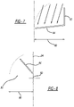
- FIGS. 8 and 9 illustrate an additional embodiment.
- the seal 90 is like that of FIGS. 5-7 , however the securement portion 92 and flap 94 are positioned in a different angular direction.
- the flap 94 is moved down on the tub during the washing operation.
- FIG. 9 illustrates the flap 94 when drying air is formed into the tub 42 and then into the drum.
- the flap 94 closes the seal gap between the seal 90 and drum 40 as illustrated.
- the tub includes a ring 100 positioned about the drum.
- the ring 100 includes a plurality of apertures 102 that enable the heating air to exit the ring.
- a seal 110 is positioned over the ring 100.
- the seal 110 includes a securement portion 112 and a flap portion 114.
- the securement portion 112 is fitted about the circumferential surfaces of the ring 100 so that the flap 114 can cover the ring apertures 102.
- FIG. 11 the seal 110 is illustrated in a drum 0 RPM position.
- the flap 114 moves to cover and seal the apertures 102 as the washing cycle is initiated.
- FIG. 12 illustrates the flap 114 moving away from the ring 100 during the drying cycle. As air enters the apertures 102, the flap 114 is moved toward the drum 40 to close the seal gap.
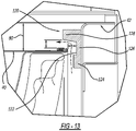
- the seal 120 is positioned on the tub 42.
- the seal includes a channel 122 that directs the air flow around the drum to provide a labyrinth seal.
- the seal includes a first step portion 124 and a second step portion 126 and a third step portion 128.
- the step portion 126 is at a smaller height than the other two and is positioned adjacent to the edge of the drum 40.
- the steps 124, 128 have a larger height such that they project closer to the drum 40.
- the steps 124, 126, 128 form the channel 122 that provides for the labyrinth flow of air passing around the seal 120.
Landscapes
- Engineering & Computer Science (AREA)
- Textile Engineering (AREA)
- Main Body Construction Of Washing Machines And Laundry Dryers (AREA)
- Detail Structures Of Washing Machines And Dryers (AREA)
Abstract
Description
- The present disclosure relates to combination washer/dryer machines and, more particularly, to a combination washer/dryer machine with a seal sealing a gap formed between the drum and tub during washing and drying operations.
- In combination washers/dryers machines, it is difficult to provide a drying cycle without a lengthy finishing drying time. Several reasons exist for the lengthy drying time of the clothes within the drum. One such reason is a gap exists between the drum and the tub. The gap enables air to bypass the drum. Thus, the drying air exits the machine without providing its heated air to the clothes within the drum. Accordingly, the drying cycle is inefficient and necessitates a longer drying time.
- It would be desirable to provide a combination washer/dryer machine with an efficient drying cycle time. It would also be desirable to utilize all of the created drying air and pass it into the drum for its intended drying purposes. Thus, it is desirable to eliminate bypasses around the drum. Drying air would be forced to enter into the drum. Accordingly, with all the drying air forced into the drum, this would, in turn, reduce the drying cycle time.
- It is also desirable to provide a combination washer/dryer machine that overcomes the deficiencies of the prior art. It is desirable to provide a combination washer/dryer machine that provides a flow restriction to avoid air from bypassing the drum. Thus, it is desirable to move substantially all of the generated heated air to enter into the drum.
- In accordance with the present disclosure, a combination washer/dryer machine comprises a cabinet, a tub positioned inside the cabinet, and a drum that is rotatable inside the tub. The tub has an inner surface and the drum has an external surface. A seal is positioned between the exterior surface of the drum and the inner surface of the tub to form a seal gap between the seal and the drum or between the seal and the tub during both washing and drying operations. The seal is configured to provide a flow restriction through the seal gap that minimizes drying air from bypassing the drum during the drying operation.
- In accordance with an additional aspect of the present disclosure, the tub has a cylindrical wall and an end wall, the drum has a cylindrical sidewall and an end plate surface, and the seal is positioned between the end wall of the tub and the end plate surface of the drum.
- In accordance with another aspect of the present disclosure, the seal includes a securement portion and a flap portion. The flap portion is dynamic and is manufactured from a material to enable the flap portion to deflect.
- In accordance with another aspect of the present disclosure, the securement portion of the seal may be attached to the drum such that the seal rotation with the drum. The flap portion of the seal may be configured to move in response to the centrifugal force created by rotation (i.e., the RPM) of the drum. For example, the flap portion of the seal may extend from the drum at a first height when the drum is in a non-rotating position and may be configured to deflect further from the drum during rotation of the drum.
- According to another aspect of the disclosure, the combination washer/dryer machine comprises a cabinet, tub mounted inside the cabinet, and a drum that is rotatable within the tub. The drum has an external surface and tub has an inner surface. A seal extends between the exterior surface of the drum and the inner surface of the tub to form a seal gap between the seal and the drum or between the seal and the tub during both washing and drying operations. The seal is configured to provide a flow restriction through the seal gap that minimizes drying air from bypassing the drum during the drying operation.
- The seal includes a securement portion and a flap portion. The flap portion is dynamic, is manufactured from a material to enable the flap portion to deflect, and is configured to move in response to the air force created by the flow of drying air through and around the drum. In accordance with this aspect of the present disclosure, the securement portion of the seal may be attached to either the drum or the tub.
- In accordance with an additional aspect of the present disclosure, the tub has a ring that includes a plurality of apertures. The apertures in the ring are covered by seal during the washing operation and the seal is configured to move away from the ring during the drying operation to enable the drying air to pass through the apertures in the ring. The drying air passing through the apertures in the ring during the drying operation moves the seal towards the drum to reduce the seal gap.
- According to another aspect of the disclosure, the combination washer/dryer machine comprises a cabinet, tub mounted inside the cabinet, and a drum that is rotatable within the tub. The drum has an external surface and tub has an inner surface. A seal extends between the exterior surface of the drum and the inner surface of the tub to form a seal gap between the seal and the drum or between the seal and the tub during both washing and drying operations. The seal is configured to provide a flow restriction through the seal gap that minimizes drying air from bypassing the drum during the drying operation. In accordance with this aspect of the present disclosure, the seal may be attached to either the drum or the tub and includes a channel that directs airflow around the drum to provide a labyrinth shaped air flow path / seal. The seal includes a first step portion, a second step portion, and a third step portion, which cooperate to form the channel. For example, in configurations where the seal is attached to the tub and the channel faces the drum, the second step portion may have a smaller height than the first and third step portions and may be positioned adjacent to an edge of the drum, while the first and third step portion may each have a larger height such that they project closer to the drum and form the channel that provides for a labyrinth flow of air passing around the seal.
- Further areas of applicability will become apparent from the description provided herein. The description and specific examples in this summary are intended for purposes of illustration only and are not intended to limit the scope of the present disclosure.
- The drawings described herein are for illustrative purposes only of selected embodiments and not all possible implementations, and are not intended to limit the scope of the present disclosure.
-
FIG. 1 is a perspective view of a combination washer/dryer machine in accordance with the disclosure. -
FIG. 2 is a schematic view in cross-section of the washer/dryer machine ofFIG. 1 . -
FIG. 3 is an enlarged cross-section view ofFIG. 2 . -
FIGS. 4A-C is a schematic cross-section view of the seal. -
FIG. 5 is a cross-section view likeFIG. 3 of an additional embodiment. -
FIG. 6 is a cross-section view likeFIG. 5 in a second position. -
FIG. 7 is a view likeFIG. 5 in an additional position. -
FIG. 8 is a cross-section view of an additional embodiment. -
FIG. 9 is a cross-section view likeFIG. 8 . -
FIG. 10 is a perspective view of a ring on the tub. -
FIG. 11 is a cross-section view ofFIG. 10 with the seal present. -
FIG. 12 is a cross-section view likeFIG. 11 in a second position. -
FIG. 13 is a cross-section view of another embodiment of the seal. - Example embodiments will now be described more fully with reference to the accompanying drawings.
- Turning to the figures, a combination washer/dryer machine is illustrated and designated with the
reference numeral 20. The combination washer/dryer machine 20 includes acabinet 24 with a plurality ofpanels 26. Thefront panel 28 includes adoor 30 to enable access into the combination washer/dryer machine 20.Controls 32 are positioned on thefront panel 28. The control controls the operation of the combination washer/dryer machine. - Turning to
FIG. 2 , a cross-section of the washer/dryer machine 20 is illustrated. The combination washer/dryer machine 20 includes adrum 40 rotationally positioned within atub 42. Thedrum 40 is rotated via amotor 44 and ashaft 46. Aconventional washing circuit 50 provides for washing of clothes within thedrum 40. Aconventional heating circuit 60 provides heat for drying the clothes within thedrum 40. Theheating circuit 60 includes aheater 62 with aconduit 64 passing heated air into thetub 42. Thedrum 40 includesapertures 43 in itsend plate 84 that enable the heated air to enter into thedrum 40. Also, thedrum 40 includesapertures 45 in thecylindrical wall 82. The heated air exits thedrum 40 through gap G as illustrated inFIG. 2 . Anoutlet 48 of thetub 42 enables exit of the air. Piping orconduit 66 connects withoutlet 48 to exit the air, via a blower orfan 68, to anexhaust tube 70. Thus, the used air is exhausted from the combination washer/dryer machine 20. Theexhaust tube 70 is connected with piping in the building to exit the air to ambient. - A
gap 80 is formed between thedrum 40 andtub 42. Thegap 80 provides for the recovery of water or the like between thedrum 40 andtub 42. Thedrum 42 has acylindrical sidewall 82 and anend plate surface 84. Likewise, thetub 42 has acylindrical wall 86 and anend wall 88. The external surface of thesidewall 82 andend wall 88 face an inner surface of thetub 42. - A
seal 90 may be connected to thedrum 40 ortub 42. Theseal 90 includes asecurement portion 92 and adynamic flap 94. Thesecurement portion 92 may secure to thedrum 40 ortub 42. Theflap 94 is manufactured from a desired material to enable the flap to deflect as needed at various RPM speeds of the drum. This enables the appropriate seal gap for the washing/drying operation. - Turning to
FIG. 4A , the flap is illustrated at a first height with the drum in a non-rotating position of 0 RPM.FIG. 4B illustrates theseal flap 94 deflection at a drum rotation speed of about 55 RPM. This partially closes the seal gap and enables approximately less than 20% of the air to bypass around thedrum 40. The speed during drying of the clothes within the drum is about 55 RPM. -
FIG. 4C illustrates theflap 94 deflected even further at a drum RPM speed of approximately 1160. This is during the washing cycle to enable a larger seal gap to be present when the combination machine is in a washing mode. - Turning to
FIGS. 5-7 , an additional embodiment is illustrated. Here, theseal 90 includes asecurement portion 92 and aflap 94. Thesecurement portion 92 is secured to the tub via rivets or the like. Theseal 90 inFIG. 5 is in a rest position of the drum.FIG. 6 illustrates theseal 90 in a washing mode with theflap 94 in a default position. As seen inFIG 6 , the flap as well as the securement portion are positioned against thetub 42 enabling the gap between the drum and tub. -
FIG. 7 illustrates theseal 90 in a drying operation. Here, the air flowing out of the tub into the drum forces theflap 94 towards the drum. This movement of thedynamic flap 94 by the drying air flow closes the seal gap between theseal 90 anddrum 40. -
FIGS. 8 and9 illustrate an additional embodiment. Here, theseal 90 is like that ofFIGS. 5-7 , however thesecurement portion 92 andflap 94 are positioned in a different angular direction. However as illustrated in the rest position inFIG. 8 , theflap 94 is moved down on the tub during the washing operation.FIG. 9 illustrates theflap 94 when drying air is formed into thetub 42 and then into the drum. Here, theflap 94 closes the seal gap between theseal 90 and drum 40 as illustrated. - Turning to
FIGS. 10 ,11 and 12 , an additional embodiment is illustrated. Here the tub includes aring 100 positioned about the drum. Thering 100 includes a plurality ofapertures 102 that enable the heating air to exit the ring. Thus, as heating air is passed into thering 100, it passes through theapertures 102. Aseal 110 is positioned over thering 100. Theseal 110 includes asecurement portion 112 and aflap portion 114. Thesecurement portion 112 is fitted about the circumferential surfaces of thering 100 so that theflap 114 can cover thering apertures 102. InFIG. 11 , theseal 110 is illustrated in a drum 0 RPM position. Theflap 114 moves to cover and seal theapertures 102 as the washing cycle is initiated.FIG. 12 illustrates theflap 114 moving away from thering 100 during the drying cycle. As air enters theapertures 102, theflap 114 is moved toward thedrum 40 to close the seal gap. - Turning to
FIG. 13 , an additional embodiment is illustrated. Here, theseal 120 is positioned on thetub 42. The seal includes achannel 122 that directs the air flow around the drum to provide a labyrinth seal. Here, the seal includes afirst step portion 124 and asecond step portion 126 and athird step portion 128. Thestep portion 126 is at a smaller height than the other two and is positioned adjacent to the edge of thedrum 40. Thesteps drum 40. Thus, thesteps channel 122 that provides for the labyrinth flow of air passing around theseal 120. - The foregoing description of the embodiments has been provided for purposes of illustration and description. It is not intended to be exhaustive or to limit the disclosure. Individual elements or features of a particular embodiment are generally not limited to that particular embodiment, but, where applicable, are interchangeable and can be used in a selected embodiment, even if not specifically shown or described. The same may also be varied in many ways. Such variations are not to be regarded as a departure from the disclosure, and all such modifications are intended to be included within the scope of the disclosure.
Claims (15)
- A combination washer/dryer machine (20), comprising:a cabinet (24);a tub (42) positioned inside the cabinet (24), the tub (42) having an inner surface;a drum (40) that is rotatable inside the tub (42), the drum (40) has an external surface; anda seal (90, 110, 120) positioned between the external surface of the drum (40) and the inner surface of the tub (42) forming a seal gap between the seal (90, 110, 120) and the drum (40) or between the seal (90, 110, 120) and the tub (42) during both washing and drying operations,wherein the seal (90, 110, 120) is configured to provide a flow restriction through the seal gap that minimizes drying air from bypassing the drum (40) during the drying operation.
- The combination washer/dryer machine (20) of Claim 1, wherein the tub (42) has a cylindrical wall and an end wall, wherein the drum (40) has a cylindrical sidewall and an end plate surface, and wherein the seal (90, 110, 120) is positioned between the end wall of the tub (42) and the end plate surface of the drum (40).
- The combination washer/dryer machine (20) of Claim 1 or 2, wherein the seal (90, 110, 120) includes a securement portion (92, 112) and a flap portion (94, 114).
- The combination washer/dryer machine (20) of Claim 3, wherein the flap portion (94) is dynamic and is manufactured from a material to enable the flap portion (94, 114) to deflect.
- The combination washer/dryer machine (20) of Claim 3 or Claim 4, wherein the flap portion (94, 114) is configured to be moveable in response to air flow.
- The combination washer/dryer machine (20) of any one of Claims 3 to 5, wherein the securement portion (92) is on the drum (40).
- The combination washer/dryer machine (20) of Claim 6, wherein the flap portion (94) is configured to be moveable in response to a centrifugal force created by rotation of the drum (40).
- The combination washer/dryer machine (20) of Claim 7, wherein the flap portion (94) extends from the drum (40) at a first height when the drum (40) is in a non-rotating position and deflects further from the drum (40) during rotation of the drum (40).
- The combination washer/dryer machine (20) of any one of Claims 3 to 5, wherein the securement portion (92, 112) is on the tub (42).
- The combination washer/dryer machine (20) of any one of Claims 1 to 5 or Claim 9, wherein the tub (42) includes a ring (100) and the seal (110) is positioned on the ring (100).
- The combination washer/dryer machine (20) of Claim 10, wherein the ring (100) includes a plurality of apertures (102) that are covered by seal (110) during the washing operation and wherein the seal (110) is moveable away from the ring (100) during the drying operation to enable the drying air to pass through the apertures (102) in the ring (100).
- The combination washer/dryer machine (20) of Claim 11, wherein the drying air passing through the apertures (102) in the ring (100) during the drying operation moves the seal (110) towards the drum (40) to reduce the seal gap between the seal (110) and the drum (40) .
- The combination washer/dryer machine (20) of Claim 1 or Claim 2, wherein the seal (120) includes a channel (122) that directs airflow around the drum (40) to provide a labyrinth seal.
- The combination washer/dryer machine (20) of Claim 13, wherein the seal (120) is positioned on the tub (42) with the channel (122) facing the drum (40).
- The combination washer/dryer machine (20) of Claim 14, wherein the seal (120) includes a first step portion, a second step portion, and a third step portion, wherein the second step portion has a smaller height than the first and third step portions and is positioned adjacent to an edge of the drum (40), and wherein the first and third step portions each has a larger height such that the first and third step portions project closer to the drum (40) and form the channel (122) that provides for a labyrinth flow of air passing around the seal (120).
Applications Claiming Priority (1)
| Application Number | Priority Date | Filing Date | Title |
|---|---|---|---|
| US17/140,369 US11846059B2 (en) | 2021-01-04 | 2021-01-04 | Controlling process air bypass around the drum in combo wash-dry system |
Publications (2)
| Publication Number | Publication Date |
|---|---|
| EP4023805A1 true EP4023805A1 (en) | 2022-07-06 |
| EP4023805B1 EP4023805B1 (en) | 2023-05-24 |
Family
ID=79021736
Family Applications (1)
| Application Number | Title | Priority Date | Filing Date |
|---|---|---|---|
| EP21217210.0A Active EP4023805B1 (en) | 2021-01-04 | 2021-12-22 | Controlling process air bypass around the drum in combo wash-dry system |
Country Status (3)
| Country | Link |
|---|---|
| US (2) | US11846059B2 (en) |
| EP (1) | EP4023805B1 (en) |
| CN (1) | CN114717789A (en) |
Families Citing this family (2)
| Publication number | Priority date | Publication date | Assignee | Title |
|---|---|---|---|---|
| DE202024106857U1 (en) | 2024-11-26 | 2026-04-23 | BSH Hausgeräte GmbH | Profile arrangement for laundry treatment machines |
| DE202024106858U1 (en) | 2024-11-26 | 2026-04-23 | BSH Hausgeräte GmbH | Laundry treatment machine with a profile arrangement |
Citations (5)
| Publication number | Priority date | Publication date | Assignee | Title |
|---|---|---|---|---|
| US20060005581A1 (en) * | 2004-05-12 | 2006-01-12 | Yoshikazu Banba | Laundry machine |
| DE112005002904T5 (en) * | 2004-11-30 | 2008-03-27 | Kabushiki Kaisha Toshiba | washer dryer |
| WO2009041345A1 (en) * | 2007-09-26 | 2009-04-02 | Sanyo Electric Co., Ltd. | Dryer |
| WO2014181493A1 (en) * | 2013-05-07 | 2014-11-13 | パナソニックIpマネジメント株式会社 | Washing and drying machine |
| US10815597B2 (en) * | 2018-05-31 | 2020-10-27 | Whirlpool Corporation | Laundry treating appliance having a liquid distribution assembly |
Family Cites Families (57)
| Publication number | Priority date | Publication date | Assignee | Title |
|---|---|---|---|---|
| US1957585A (en) | 1933-01-30 | 1934-05-08 | Organ valve | |
| US2569515A (en) | 1946-08-10 | 1951-10-02 | Smith Corp A O | Damper for clothes driers |
| US2864394A (en) | 1954-05-27 | 1958-12-16 | Mcdowell Mfg Co | Automatic relief valve |
| US3066695A (en) | 1956-06-04 | 1962-12-04 | Stewart Warner Corp | Check valve |
| US3247690A (en) * | 1962-04-11 | 1966-04-26 | Leo M Kahn | Clothes and fabric processing machine |
| US3163029A (en) | 1962-12-13 | 1964-12-29 | Gen Motors Corp | Clothes conditioning apparatus |
| US3584650A (en) | 1968-10-22 | 1971-06-15 | Rca Corp | Reed armature valves for controlling fluid flow |
| US3750304A (en) | 1971-09-24 | 1973-08-07 | Westinghouse Electric Corp | Semi-recirculatory system for a clothes dryer |
| US3807444A (en) | 1972-10-10 | 1974-04-30 | Ca Valve Ltd | Check valve |
| US3875686A (en) | 1974-01-28 | 1975-04-08 | Schlegel Mfg Co | Seal for clothes dryer |
| US4006534A (en) | 1975-08-22 | 1977-02-08 | Norman Dryer Co., Inc. | Variable air supply for fabric dryers |
| JPS61248959A (en) | 1985-04-27 | 1986-11-06 | Mazda Motor Corp | Device for locking up automatic transmission |
| US4669200A (en) | 1985-11-27 | 1987-06-02 | Whirlpool Corporation | Bulkhead seal for clothes dryer |
| US4835882A (en) | 1987-10-30 | 1989-06-06 | Challenge Cook Bros., Inc. | Dryer flow separator |
| DE3929023C1 (en) | 1989-09-01 | 1990-09-06 | Mercedes-Benz Aktiengesellschaft, 7000 Stuttgart, De | Sound-absorbing radiator grille - is for heavy vehicle and has flaps made of plastics material |
| US5325892A (en) | 1992-05-29 | 1994-07-05 | Minnesota Mining And Manufacturing Company | Unidirectional fluid valve |
| KR960008601Y1 (en) | 1993-11-22 | 1996-10-04 | 대우중공업 주식회사 | Device with disk spring for controlling flow |
| DE19503367C2 (en) | 1995-02-02 | 2002-04-25 | Bsh Bosch Siemens Hausgeraete | Sealing arrangement for a household clothes dryer |
| US5601117A (en) | 1995-02-21 | 1997-02-11 | Trw Inc. | Flap-type pressure relief valve |
| DE19828243A1 (en) | 1998-06-25 | 1999-12-30 | Aeg Hausgeraete Gmbh | Laundry dryer has drum located in washing solution container |
| US6006445A (en) | 1998-09-03 | 1999-12-28 | Large; Ronald D. | Washer/dryer combination |
| DE19907602C2 (en) | 1999-02-22 | 2002-08-01 | Miele & Cie | Seal for a clothes dryer |
| DE10056358A1 (en) * | 2000-11-14 | 2002-05-23 | Pharmagg Systemtechnik Gmbh | Device for wet treatment of laundry and seal for such a device |
| JP2003026293A (en) | 2001-07-17 | 2003-01-29 | Sanyo Electric Co Ltd | Beverage dispenser |
| JP2004008683A (en) | 2002-06-11 | 2004-01-15 | Toshiba Corp | Washing and drying machine |
| KR20050037187A (en) | 2003-10-17 | 2005-04-21 | 엘지전자 주식회사 | Clothes dryer |
| KR100546613B1 (en) | 2003-12-19 | 2006-01-26 | 엘지전자 주식회사 | Drum washing machine |
| FR2865742B1 (en) | 2004-01-30 | 2006-06-02 | Brandt Ind | WASHING AND DRYING MACHINE AND METHOD OF DRYING LAUNDRY. |
| JP4541023B2 (en) * | 2004-04-26 | 2010-09-08 | パナソニック株式会社 | Washing and drying machine |
| KR100529954B1 (en) | 2004-05-29 | 2005-11-22 | 엘지전자 주식회사 | Variable gasket apparatus for drum washer and control method therefor |
| JP4444016B2 (en) | 2004-06-17 | 2010-03-31 | パナソニック株式会社 | Clothes dryer |
| KR100697083B1 (en) | 2005-04-06 | 2007-03-20 | 엘지전자 주식회사 | Drying Washer |
| JP2007061548A (en) | 2005-09-02 | 2007-03-15 | Toshiba Corp | Washing and drying machine |
| DE102005056140B3 (en) | 2005-11-23 | 2006-11-30 | Miele & Cie. Kg | Seal for a wash drier has hollow rubber ring seal with hollow enclosed by two V-shaped sealing lips and an end support part |
| JP2006122697A (en) | 2005-12-26 | 2006-05-18 | Sanyo Electric Co Ltd | Drum type washing and drying machine |
| JP4945154B2 (en) | 2006-03-16 | 2012-06-06 | 株式会社東芝 | Washing and drying machine |
| JP2008220817A (en) * | 2007-03-15 | 2008-09-25 | Sanyo Electric Co Ltd | Washing and drying machine |
| WO2008148509A2 (en) * | 2007-06-07 | 2008-12-11 | Aktiebolaget Electrolux | Washing machine and dryer |
| DE102008043348A1 (en) | 2008-10-31 | 2010-05-06 | BSH Bosch und Siemens Hausgeräte GmbH | Air-guiding part arrangement for use in vented dryer utilized for maintaining pieces of laundry, has seal provided between air-guiding parts and designed as lateral seal between air-guiding parts |
| EP2423370B1 (en) | 2010-08-24 | 2013-04-17 | Electrolux Home Products Corporation N.V. | Rotary-drum laundry dryer |
| EP2423375B1 (en) | 2010-08-24 | 2015-12-02 | Electrolux Home Products Corporation N.V. | Rotary-drum laundry dryer |
| US20130174435A1 (en) | 2011-11-22 | 2013-07-11 | Owens Corning Intellectual Capital, Llc | Nonwoven material and dryer with nonwoven material |
| EP2660384B1 (en) | 2012-05-04 | 2016-02-10 | Girbau, S.A. | Laundry dryer with suction-assisted loading device |
| DE102012207977A1 (en) | 2012-05-14 | 2013-11-14 | BSH Bosch und Siemens Hausgeräte GmbH | Laundry appliance |
| US9970705B2 (en) | 2013-04-01 | 2018-05-15 | Felters Of South Carolina, Llc | High temperature dryer seals and related methods |
| CN103255598A (en) * | 2013-06-02 | 2013-08-21 | 任文涛 | Roller washing machine washing clothes separately |
| WO2016050295A1 (en) | 2014-10-01 | 2016-04-07 | Arcelik Anonim Sirketi | Laundry drying machine having a structurally improved leak-proofing system |
| KR101632013B1 (en) | 2014-12-08 | 2016-06-21 | 엘지전자 주식회사 | Condensing type clothes dryer having a heat pump cycle and control method for the same |
| CN106283561B (en) | 2015-05-29 | 2019-12-17 | 无锡小天鹅电器有限公司 | Clothes dryer |
| US9580856B1 (en) | 2015-08-10 | 2017-02-28 | Whirlpool Corporation | Clothes dryer with a drum seal |
| EP3469135B1 (en) | 2016-06-08 | 2020-01-22 | Arçelik Anonim Sirketi | A washer / dryer wherein air and water tightness is provided between the tub and the drum |
| CN107558092B (en) | 2016-07-01 | 2021-02-09 | 浙江三花智能控制股份有限公司 | Washing and drying integrated machine |
| KR20180055420A (en) | 2016-11-17 | 2018-05-25 | 엘지전자 주식회사 | Laundry treating machine |
| KR20180055419A (en) | 2016-11-17 | 2018-05-25 | 엘지전자 주식회사 | Laundry treating machine |
| CN108625132B (en) | 2017-03-24 | 2020-09-11 | 青岛胶南海尔洗衣机有限公司 | Dryer drum sealing device |
| EP3741898B1 (en) | 2019-05-21 | 2023-08-02 | BSH Hausgeräte GmbH | Device for washing and drying objects and method for operating such a device |
| US11795601B2 (en) | 2020-11-10 | 2023-10-24 | Whirlpool Corporation | Maximizing the dry rate of clothes tumbling combination washer/dryer with a seal |
-
2021
- 2021-01-04 US US17/140,369 patent/US11846059B2/en active Active
- 2021-12-22 EP EP21217210.0A patent/EP4023805B1/en active Active
- 2021-12-31 CN CN202111659820.8A patent/CN114717789A/en active Pending
-
2023
- 2023-11-16 US US18/510,895 patent/US12325944B2/en active Active
Patent Citations (5)
| Publication number | Priority date | Publication date | Assignee | Title |
|---|---|---|---|---|
| US20060005581A1 (en) * | 2004-05-12 | 2006-01-12 | Yoshikazu Banba | Laundry machine |
| DE112005002904T5 (en) * | 2004-11-30 | 2008-03-27 | Kabushiki Kaisha Toshiba | washer dryer |
| WO2009041345A1 (en) * | 2007-09-26 | 2009-04-02 | Sanyo Electric Co., Ltd. | Dryer |
| WO2014181493A1 (en) * | 2013-05-07 | 2014-11-13 | パナソニックIpマネジメント株式会社 | Washing and drying machine |
| US10815597B2 (en) * | 2018-05-31 | 2020-10-27 | Whirlpool Corporation | Laundry treating appliance having a liquid distribution assembly |
Also Published As
| Publication number | Publication date |
|---|---|
| EP4023805B1 (en) | 2023-05-24 |
| CN114717789A (en) | 2022-07-08 |
| US20240084489A1 (en) | 2024-03-14 |
| US12325944B2 (en) | 2025-06-10 |
| US11846059B2 (en) | 2023-12-19 |
| US20220213631A1 (en) | 2022-07-07 |
Similar Documents
| Publication | Publication Date | Title |
|---|---|---|
| US12325944B2 (en) | Controlling process air bypass around the drum in combo wash-dry system | |
| US11795601B2 (en) | Maximizing the dry rate of clothes tumbling combination washer/dryer with a seal | |
| EP1389644B1 (en) | Air-exhaust type clothes tumble dryer | |
| EP2539502B1 (en) | Dryer | |
| EP2436830B1 (en) | Tunnel-type rotary-drum tumble dryer | |
| WO2014181493A1 (en) | Washing and drying machine | |
| US20180051409A1 (en) | Fan assembly for a dryer appliance | |
| JP2005034163A (en) | Washing machine with clothes drying function | |
| US5121615A (en) | Drying device incorporated with a washing machine | |
| JP2015039563A (en) | Washing and drying machine | |
| JP6871564B2 (en) | Washing and drying machine | |
| EP3919665B1 (en) | Dryer for drying laundry and method of operating a dryer | |
| CN116096956A (en) | Dryer | |
| KR20190000515A (en) | Clothes dryer | |
| JP2017200564A (en) | Washing and drying machine | |
| JPS58221989A (en) | Drum type dryer | |
| CN107313205B (en) | Washing and drying machine | |
| EP4012090A1 (en) | Air flow bypass controlling mechanism for no compromise combo | |
| JP4945154B2 (en) | Washing and drying machine | |
| JP4052216B2 (en) | Air conditioner | |
| KR20230111050A (en) | Apparatus for treating laundry and method for controlling thereof | |
| KR100610664B1 (en) | Clothes dryer | |
| JP7503259B2 (en) | Dryer | |
| JP7830300B2 (en) | Washer dryer | |
| EP4050148A1 (en) | Laundry treating apparatus |
Legal Events
| Date | Code | Title | Description |
|---|---|---|---|
| PUAI | Public reference made under article 153(3) epc to a published international application that has entered the european phase |
Free format text: ORIGINAL CODE: 0009012 |
|
| STAA | Information on the status of an ep patent application or granted ep patent |
Free format text: STATUS: THE APPLICATION HAS BEEN PUBLISHED |
|
| AK | Designated contracting states |
Kind code of ref document: A1 Designated state(s): AL AT BE BG CH CY CZ DE DK EE ES FI FR GB GR HR HU IE IS IT LI LT LU LV MC MK MT NL NO PL PT RO RS SE SI SK SM TR |
|
| STAA | Information on the status of an ep patent application or granted ep patent |
Free format text: STATUS: REQUEST FOR EXAMINATION WAS MADE |
|
| 17P | Request for examination filed |
Effective date: 20230109 |
|
| RBV | Designated contracting states (corrected) |
Designated state(s): AL AT BE BG CH CY CZ DE DK EE ES FI FR GB GR HR HU IE IS IT LI LT LU LV MC MK MT NL NO PL PT RO RS SE SI SK SM TR |
|
| GRAP | Despatch of communication of intention to grant a patent |
Free format text: ORIGINAL CODE: EPIDOSNIGR1 |
|
| STAA | Information on the status of an ep patent application or granted ep patent |
Free format text: STATUS: GRANT OF PATENT IS INTENDED |
|
| RIC1 | Information provided on ipc code assigned before grant |
Ipc: D06F 37/04 20060101ALN20230214BHEP Ipc: D06F 37/02 20060101ALN20230214BHEP Ipc: D06F 58/04 20060101ALN20230214BHEP Ipc: D06F 37/26 20060101ALI20230214BHEP Ipc: D06F 25/00 20060101AFI20230214BHEP |
|
| INTG | Intention to grant announced |
Effective date: 20230303 |
|
| GRAS | Grant fee paid |
Free format text: ORIGINAL CODE: EPIDOSNIGR3 |
|
| GRAA | (expected) grant |
Free format text: ORIGINAL CODE: 0009210 |
|
| STAA | Information on the status of an ep patent application or granted ep patent |
Free format text: STATUS: THE PATENT HAS BEEN GRANTED |
|
| AK | Designated contracting states |
Kind code of ref document: B1 Designated state(s): AL AT BE BG CH CY CZ DE DK EE ES FI FR GB GR HR HU IE IS IT LI LT LU LV MC MK MT NL NO PL PT RO RS SE SI SK SM TR |
|
| REG | Reference to a national code |
Ref country code: GB Ref legal event code: FG4D |
|
| REG | Reference to a national code |
Ref country code: CH Ref legal event code: EP |
|
| REG | Reference to a national code |
Ref country code: DE Ref legal event code: R096 Ref document number: 602021002478 Country of ref document: DE |
|
| REG | Reference to a national code |
Ref country code: AT Ref legal event code: REF Ref document number: 1569538 Country of ref document: AT Kind code of ref document: T Effective date: 20230615 |
|
| REG | Reference to a national code |
Ref country code: IE Ref legal event code: FG4D |
|
| P01 | Opt-out of the competence of the unified patent court (upc) registered |
Effective date: 20230530 |
|
| REG | Reference to a national code |
Ref country code: LT Ref legal event code: MG9D |
|
| REG | Reference to a national code |
Ref country code: NL Ref legal event code: MP Effective date: 20230524 |
|
| REG | Reference to a national code |
Ref country code: AT Ref legal event code: MK05 Ref document number: 1569538 Country of ref document: AT Kind code of ref document: T Effective date: 20230524 |
|
| PG25 | Lapsed in a contracting state [announced via postgrant information from national office to epo] |
Ref country code: SE Free format text: LAPSE BECAUSE OF FAILURE TO SUBMIT A TRANSLATION OF THE DESCRIPTION OR TO PAY THE FEE WITHIN THE PRESCRIBED TIME-LIMIT Effective date: 20230524 Ref country code: PT Free format text: LAPSE BECAUSE OF FAILURE TO SUBMIT A TRANSLATION OF THE DESCRIPTION OR TO PAY THE FEE WITHIN THE PRESCRIBED TIME-LIMIT Effective date: 20230925 Ref country code: NO Free format text: LAPSE BECAUSE OF FAILURE TO SUBMIT A TRANSLATION OF THE DESCRIPTION OR TO PAY THE FEE WITHIN THE PRESCRIBED TIME-LIMIT Effective date: 20230824 Ref country code: NL Free format text: LAPSE BECAUSE OF FAILURE TO SUBMIT A TRANSLATION OF THE DESCRIPTION OR TO PAY THE FEE WITHIN THE PRESCRIBED TIME-LIMIT Effective date: 20230524 Ref country code: ES Free format text: LAPSE BECAUSE OF FAILURE TO SUBMIT A TRANSLATION OF THE DESCRIPTION OR TO PAY THE FEE WITHIN THE PRESCRIBED TIME-LIMIT Effective date: 20230524 Ref country code: AT Free format text: LAPSE BECAUSE OF FAILURE TO SUBMIT A TRANSLATION OF THE DESCRIPTION OR TO PAY THE FEE WITHIN THE PRESCRIBED TIME-LIMIT Effective date: 20230524 |
|
| PG25 | Lapsed in a contracting state [announced via postgrant information from national office to epo] |
Ref country code: RS Free format text: LAPSE BECAUSE OF FAILURE TO SUBMIT A TRANSLATION OF THE DESCRIPTION OR TO PAY THE FEE WITHIN THE PRESCRIBED TIME-LIMIT Effective date: 20230524 Ref country code: PL Free format text: LAPSE BECAUSE OF FAILURE TO SUBMIT A TRANSLATION OF THE DESCRIPTION OR TO PAY THE FEE WITHIN THE PRESCRIBED TIME-LIMIT Effective date: 20230524 Ref country code: LV Free format text: LAPSE BECAUSE OF FAILURE TO SUBMIT A TRANSLATION OF THE DESCRIPTION OR TO PAY THE FEE WITHIN THE PRESCRIBED TIME-LIMIT Effective date: 20230524 Ref country code: LT Free format text: LAPSE BECAUSE OF FAILURE TO SUBMIT A TRANSLATION OF THE DESCRIPTION OR TO PAY THE FEE WITHIN THE PRESCRIBED TIME-LIMIT Effective date: 20230524 Ref country code: IS Free format text: LAPSE BECAUSE OF FAILURE TO SUBMIT A TRANSLATION OF THE DESCRIPTION OR TO PAY THE FEE WITHIN THE PRESCRIBED TIME-LIMIT Effective date: 20230924 Ref country code: HR Free format text: LAPSE BECAUSE OF FAILURE TO SUBMIT A TRANSLATION OF THE DESCRIPTION OR TO PAY THE FEE WITHIN THE PRESCRIBED TIME-LIMIT Effective date: 20230524 Ref country code: GR Free format text: LAPSE BECAUSE OF FAILURE TO SUBMIT A TRANSLATION OF THE DESCRIPTION OR TO PAY THE FEE WITHIN THE PRESCRIBED TIME-LIMIT Effective date: 20230825 |
|
| PG25 | Lapsed in a contracting state [announced via postgrant information from national office to epo] |
Ref country code: FI Free format text: LAPSE BECAUSE OF FAILURE TO SUBMIT A TRANSLATION OF THE DESCRIPTION OR TO PAY THE FEE WITHIN THE PRESCRIBED TIME-LIMIT Effective date: 20230524 |
|
| PG25 | Lapsed in a contracting state [announced via postgrant information from national office to epo] |
Ref country code: SK Free format text: LAPSE BECAUSE OF FAILURE TO SUBMIT A TRANSLATION OF THE DESCRIPTION OR TO PAY THE FEE WITHIN THE PRESCRIBED TIME-LIMIT Effective date: 20230524 |
|
| PG25 | Lapsed in a contracting state [announced via postgrant information from national office to epo] |
Ref country code: SM Free format text: LAPSE BECAUSE OF FAILURE TO SUBMIT A TRANSLATION OF THE DESCRIPTION OR TO PAY THE FEE WITHIN THE PRESCRIBED TIME-LIMIT Effective date: 20230524 Ref country code: SK Free format text: LAPSE BECAUSE OF FAILURE TO SUBMIT A TRANSLATION OF THE DESCRIPTION OR TO PAY THE FEE WITHIN THE PRESCRIBED TIME-LIMIT Effective date: 20230524 Ref country code: RO Free format text: LAPSE BECAUSE OF FAILURE TO SUBMIT A TRANSLATION OF THE DESCRIPTION OR TO PAY THE FEE WITHIN THE PRESCRIBED TIME-LIMIT Effective date: 20230524 Ref country code: EE Free format text: LAPSE BECAUSE OF FAILURE TO SUBMIT A TRANSLATION OF THE DESCRIPTION OR TO PAY THE FEE WITHIN THE PRESCRIBED TIME-LIMIT Effective date: 20230524 Ref country code: DK Free format text: LAPSE BECAUSE OF FAILURE TO SUBMIT A TRANSLATION OF THE DESCRIPTION OR TO PAY THE FEE WITHIN THE PRESCRIBED TIME-LIMIT Effective date: 20230524 Ref country code: CZ Free format text: LAPSE BECAUSE OF FAILURE TO SUBMIT A TRANSLATION OF THE DESCRIPTION OR TO PAY THE FEE WITHIN THE PRESCRIBED TIME-LIMIT Effective date: 20230524 |
|
| PGFP | Annual fee paid to national office [announced via postgrant information from national office to epo] |
Ref country code: FR Payment date: 20231226 Year of fee payment: 3 |
|
| REG | Reference to a national code |
Ref country code: DE Ref legal event code: R097 Ref document number: 602021002478 Country of ref document: DE |
|
| PLBE | No opposition filed within time limit |
Free format text: ORIGINAL CODE: 0009261 |
|
| STAA | Information on the status of an ep patent application or granted ep patent |
Free format text: STATUS: NO OPPOSITION FILED WITHIN TIME LIMIT |
|
| PGFP | Annual fee paid to national office [announced via postgrant information from national office to epo] |
Ref country code: DE Payment date: 20231227 Year of fee payment: 3 |
|
| 26N | No opposition filed |
Effective date: 20240227 |
|
| PG25 | Lapsed in a contracting state [announced via postgrant information from national office to epo] |
Ref country code: SI Free format text: LAPSE BECAUSE OF FAILURE TO SUBMIT A TRANSLATION OF THE DESCRIPTION OR TO PAY THE FEE WITHIN THE PRESCRIBED TIME-LIMIT Effective date: 20230524 |
|
| PG25 | Lapsed in a contracting state [announced via postgrant information from national office to epo] |
Ref country code: SI Free format text: LAPSE BECAUSE OF FAILURE TO SUBMIT A TRANSLATION OF THE DESCRIPTION OR TO PAY THE FEE WITHIN THE PRESCRIBED TIME-LIMIT Effective date: 20230524 |
|
| PG25 | Lapsed in a contracting state [announced via postgrant information from national office to epo] |
Ref country code: LU Free format text: LAPSE BECAUSE OF NON-PAYMENT OF DUE FEES Effective date: 20231222 |
|
| PG25 | Lapsed in a contracting state [announced via postgrant information from national office to epo] |
Ref country code: MC Free format text: LAPSE BECAUSE OF FAILURE TO SUBMIT A TRANSLATION OF THE DESCRIPTION OR TO PAY THE FEE WITHIN THE PRESCRIBED TIME-LIMIT Effective date: 20230524 |
|
| REG | Reference to a national code |
Ref country code: BE Ref legal event code: MM Effective date: 20231231 |
|
| PG25 | Lapsed in a contracting state [announced via postgrant information from national office to epo] |
Ref country code: MC Free format text: LAPSE BECAUSE OF FAILURE TO SUBMIT A TRANSLATION OF THE DESCRIPTION OR TO PAY THE FEE WITHIN THE PRESCRIBED TIME-LIMIT Effective date: 20230524 Ref country code: LU Free format text: LAPSE BECAUSE OF NON-PAYMENT OF DUE FEES Effective date: 20231222 |
|
| REG | Reference to a national code |
Ref country code: IE Ref legal event code: MM4A |
|
| PG25 | Lapsed in a contracting state [announced via postgrant information from national office to epo] |
Ref country code: IE Free format text: LAPSE BECAUSE OF NON-PAYMENT OF DUE FEES Effective date: 20231222 |
|
| PG25 | Lapsed in a contracting state [announced via postgrant information from national office to epo] |
Ref country code: BE Free format text: LAPSE BECAUSE OF NON-PAYMENT OF DUE FEES Effective date: 20231231 |
|
| PG25 | Lapsed in a contracting state [announced via postgrant information from national office to epo] |
Ref country code: IE Free format text: LAPSE BECAUSE OF NON-PAYMENT OF DUE FEES Effective date: 20231222 Ref country code: BE Free format text: LAPSE BECAUSE OF NON-PAYMENT OF DUE FEES Effective date: 20231231 |
|
| PG25 | Lapsed in a contracting state [announced via postgrant information from national office to epo] |
Ref country code: BG Free format text: LAPSE BECAUSE OF FAILURE TO SUBMIT A TRANSLATION OF THE DESCRIPTION OR TO PAY THE FEE WITHIN THE PRESCRIBED TIME-LIMIT Effective date: 20230524 |
|
| PG25 | Lapsed in a contracting state [announced via postgrant information from national office to epo] |
Ref country code: BG Free format text: LAPSE BECAUSE OF FAILURE TO SUBMIT A TRANSLATION OF THE DESCRIPTION OR TO PAY THE FEE WITHIN THE PRESCRIBED TIME-LIMIT Effective date: 20230524 |
|
| PGFP | Annual fee paid to national office [announced via postgrant information from national office to epo] |
Ref country code: IT Payment date: 20241231 Year of fee payment: 4 |
|
| REG | Reference to a national code |
Ref country code: DE Ref legal event code: R119 Ref document number: 602021002478 Country of ref document: DE |
|
| PG25 | Lapsed in a contracting state [announced via postgrant information from national office to epo] |
Ref country code: CY Free format text: LAPSE BECAUSE OF FAILURE TO SUBMIT A TRANSLATION OF THE DESCRIPTION OR TO PAY THE FEE WITHIN THE PRESCRIBED TIME-LIMIT; INVALID AB INITIO Effective date: 20211222 |
|
| REG | Reference to a national code |
Ref country code: CH Ref legal event code: PL |
|
| PG25 | Lapsed in a contracting state [announced via postgrant information from national office to epo] |
Ref country code: DE Free format text: LAPSE BECAUSE OF NON-PAYMENT OF DUE FEES Effective date: 20250701 |
|
| PG25 | Lapsed in a contracting state [announced via postgrant information from national office to epo] |
Ref country code: FR Free format text: LAPSE BECAUSE OF NON-PAYMENT OF DUE FEES Effective date: 20241231 |
|
| PG25 | Lapsed in a contracting state [announced via postgrant information from national office to epo] |
Ref country code: CH Free format text: LAPSE BECAUSE OF NON-PAYMENT OF DUE FEES Effective date: 20241231 |
|
| PG25 | Lapsed in a contracting state [announced via postgrant information from national office to epo] |
Ref country code: TR Free format text: LAPSE BECAUSE OF FAILURE TO SUBMIT A TRANSLATION OF THE DESCRIPTION OR TO PAY THE FEE WITHIN THE PRESCRIBED TIME-LIMIT Effective date: 20230524 |
|
| PG25 | Lapsed in a contracting state [announced via postgrant information from national office to epo] |
Ref country code: HU Free format text: LAPSE BECAUSE OF FAILURE TO SUBMIT A TRANSLATION OF THE DESCRIPTION OR TO PAY THE FEE WITHIN THE PRESCRIBED TIME-LIMIT; INVALID AB INITIO Effective date: 20211222 |