EP4023568A1 - Overhead carrier vehicle and overhead carrier vehicle system - Google Patents
Overhead carrier vehicle and overhead carrier vehicle system Download PDFInfo
- Publication number
- EP4023568A1 EP4023568A1 EP20857924.3A EP20857924A EP4023568A1 EP 4023568 A1 EP4023568 A1 EP 4023568A1 EP 20857924 A EP20857924 A EP 20857924A EP 4023568 A1 EP4023568 A1 EP 4023568A1
- Authority
- EP
- European Patent Office
- Prior art keywords
- vibration
- unit
- overhead transport
- transport vehicle
- monitoring unit
- Prior art date
- Legal status (The legal status is an assumption and is not a legal conclusion. Google has not performed a legal analysis and makes no representation as to the accuracy of the status listed.)
- Granted
Links
Images



Classifications
-
- B—PERFORMING OPERATIONS; TRANSPORTING
- B65—CONVEYING; PACKING; STORING; HANDLING THIN OR FILAMENTARY MATERIAL
- B65G—TRANSPORT OR STORAGE DEVICES, e.g. CONVEYORS FOR LOADING OR TIPPING, SHOP CONVEYOR SYSTEMS OR PNEUMATIC TUBE CONVEYORS
- B65G1/00—Storing articles, individually or in orderly arrangement, in warehouses or magazines
-
- B—PERFORMING OPERATIONS; TRANSPORTING
- B65—CONVEYING; PACKING; STORING; HANDLING THIN OR FILAMENTARY MATERIAL
- B65G—TRANSPORT OR STORAGE DEVICES, e.g. CONVEYORS FOR LOADING OR TIPPING, SHOP CONVEYOR SYSTEMS OR PNEUMATIC TUBE CONVEYORS
- B65G47/00—Article or material-handling devices associated with conveyors; Methods employing such devices
- B65G47/74—Feeding, transfer, or discharging devices of particular kinds or types
- B65G47/90—Devices for picking-up and depositing articles or materials
-
- B—PERFORMING OPERATIONS; TRANSPORTING
- B65—CONVEYING; PACKING; STORING; HANDLING THIN OR FILAMENTARY MATERIAL
- B65G—TRANSPORT OR STORAGE DEVICES, e.g. CONVEYORS FOR LOADING OR TIPPING, SHOP CONVEYOR SYSTEMS OR PNEUMATIC TUBE CONVEYORS
- B65G1/00—Storing articles, individually or in orderly arrangement, in warehouses or magazines
- B65G1/02—Storage devices
- B65G1/04—Storage devices mechanical
- B65G1/0457—Storage devices mechanical with suspended load carriers
-
- B—PERFORMING OPERATIONS; TRANSPORTING
- B65—CONVEYING; PACKING; STORING; HANDLING THIN OR FILAMENTARY MATERIAL
- B65G—TRANSPORT OR STORAGE DEVICES, e.g. CONVEYORS FOR LOADING OR TIPPING, SHOP CONVEYOR SYSTEMS OR PNEUMATIC TUBE CONVEYORS
- B65G1/00—Storing articles, individually or in orderly arrangement, in warehouses or magazines
- B65G1/02—Storage devices
- B65G1/04—Storage devices mechanical
- B65G1/0464—Storage devices mechanical with access from above
-
- H—ELECTRICITY
- H10—SEMICONDUCTOR DEVICES; ELECTRIC SOLID-STATE DEVICES NOT OTHERWISE PROVIDED FOR
- H10P—GENERIC PROCESSES OR APPARATUS FOR THE MANUFACTURE OR TREATMENT OF DEVICES COVERED BY CLASS H10
- H10P72/00—Handling or holding of wafers, substrates or devices during manufacture or treatment thereof
- H10P72/06—Apparatus for monitoring, sorting, marking, testing or measuring
- H10P72/0604—Process monitoring, e.g. flow or thickness monitoring
-
- H—ELECTRICITY
- H10—SEMICONDUCTOR DEVICES; ELECTRIC SOLID-STATE DEVICES NOT OTHERWISE PROVIDED FOR
- H10P—GENERIC PROCESSES OR APPARATUS FOR THE MANUFACTURE OR TREATMENT OF DEVICES COVERED BY CLASS H10
- H10P72/00—Handling or holding of wafers, substrates or devices during manufacture or treatment thereof
- H10P72/30—Handling or holding of wafers, substrates or devices during manufacture or treatment thereof for conveying, e.g. between different workstations
- H10P72/32—Handling or holding of wafers, substrates or devices during manufacture or treatment thereof for conveying, e.g. between different workstations between different workstations
- H10P72/3218—Conveying cassettes, containers or carriers
-
- H—ELECTRICITY
- H10—SEMICONDUCTOR DEVICES; ELECTRIC SOLID-STATE DEVICES NOT OTHERWISE PROVIDED FOR
- H10P—GENERIC PROCESSES OR APPARATUS FOR THE MANUFACTURE OR TREATMENT OF DEVICES COVERED BY CLASS H10
- H10P72/00—Handling or holding of wafers, substrates or devices during manufacture or treatment thereof
- H10P72/30—Handling or holding of wafers, substrates or devices during manufacture or treatment thereof for conveying, e.g. between different workstations
- H10P72/32—Handling or holding of wafers, substrates or devices during manufacture or treatment thereof for conveying, e.g. between different workstations between different workstations
- H10P72/3221—Overhead conveying
-
- B—PERFORMING OPERATIONS; TRANSPORTING
- B65—CONVEYING; PACKING; STORING; HANDLING THIN OR FILAMENTARY MATERIAL
- B65G—TRANSPORT OR STORAGE DEVICES, e.g. CONVEYORS FOR LOADING OR TIPPING, SHOP CONVEYOR SYSTEMS OR PNEUMATIC TUBE CONVEYORS
- B65G2201/00—Indexing codes relating to handling devices, e.g. conveyors, characterised by the type of product or load being conveyed or handled
- B65G2201/02—Articles
- B65G2201/0297—Wafer cassette
Definitions
- this conventional diagnostic system needs to be provided with the diagnostic device configured to perform advanced analysis and diagnosis based on various types of information transmitted from the overhead transport vehicle, the need that a vibration generated in an article gripped by the lifting unit can be grasped with a simple configuration cannot be satisfied. Furthermore, because this conventional diagnostic system is configured to transmit vibration information acquired by the vibration sensor without processing it and also transmit the output torques and the numbers of revolutions, processing load including communication in a body control unit equipped on the overhead transport vehicle increases.
- the traveling unit 18 includes a motor to cause the overhead transport vehicle 6 to travel along the track 4.
- the transfer device 7 includes a body unit 22, a cross-feed unit 24, a ⁇ drive 26, a lifting drive unit 28, a lifting unit 30, and front and rear frames 33, 33.
- the transport controller 70 illustrated in FIG. 2 controls the overhead transport vehicles 6.
- the transport controller 70 is an electronic control unit including a CPU, a ROM, and a RAM.
- the transport controller 70 can be configured, for example, as software such that a program stored in the ROM is loaded into the RAM to be executed by the CPU.
- the transport controller 70 may be configured as hardware such as an electronic circuit.
- the transport controller 70 includes a transport control unit 71, a state monitoring unit 72, and a storage unit 73 that are configured by cooperative operation of hardware such as the CPU, the RAM, and the ROM and software such as a program.
- the transport controller 70 When having received the abnormal vibration information output from the body controller 50, the transport controller 70 stores the abnormal vibration information in the storage unit 73 (step S21). The transport controller 70 then outputs the abnormal vibration information stored in the storage unit 73 to the terminal device 80 (step S22).
- the terminal device 80 include a display, a mobile terminal, a smart phone, and a tablet. The terminal device 80 displays the abnormal vibration information transmitted from the transport controller 70 as the vibration monitoring screen SC1 as illustrated in FIG. 5 .
Landscapes
- Engineering & Computer Science (AREA)
- Mechanical Engineering (AREA)
- Control And Safety Of Cranes (AREA)
- Warehouses Or Storage Devices (AREA)
- Container, Conveyance, Adherence, Positioning, Of Wafer (AREA)
- Carriers, Traveling Bodies, And Overhead Traveling Cranes (AREA)
- Transition And Organic Metals Composition Catalysts For Addition Polymerization (AREA)
- Fittings On The Vehicle Exterior For Carrying Loads, And Devices For Holding Or Mounting Articles (AREA)
- Vehicle Step Arrangements And Article Storage (AREA)
- Forklifts And Lifting Vehicles (AREA)
Abstract
Description
- One aspect of the present invention relates to an overhead transport vehicle and an overhead transport vehicle system.
- An overhead transport vehicle including: a body unit capable of traveling along a track; and a lifting unit including a gripping part configured to grip an article and configured to ascend and descend with respect to the body unit by winding and paying out a plurality of suspending members is known. For this overhead transport vehicle, there is such a need that a vibration generated in an article gripped by the lifting unit can be monitored with a simple configuration. For example,
Patent Document 1 discloses a diagnostic system in which an overhead transport vehicle is provided with a vibration sensor, and a vibration detected by a vibration sensor is transmitted together with the output torques and the numbers of revolutions, for example, of a traveling motor and a lifting motor to a diagnostic device provided outside the overhead transport vehicle, whereby the diagnostic device can automatically diagnose the overhead transport vehicle. - [Patent Document 1]
Japanese Unexamined Patent Publication No. 2006-315813 - However, because this conventional diagnostic system needs to be provided with the diagnostic device configured to perform advanced analysis and diagnosis based on various types of information transmitted from the overhead transport vehicle, the need that a vibration generated in an article gripped by the lifting unit can be grasped with a simple configuration cannot be satisfied. Furthermore, because this conventional diagnostic system is configured to transmit vibration information acquired by the vibration sensor without processing it and also transmit the output torques and the numbers of revolutions, processing load including communication in a body control unit equipped on the overhead transport vehicle increases.
- In view of this, it is an object of one aspect of the present invention to provide an overhead transport vehicle and an overhead transport vehicle system that can monitor a vibration generated in an article gripped by a lifting unit with a simple configuration without increasing processing load in a body control unit equipped on the overhead transport vehicle.
- An overhead transport vehicle according to one aspect of the present invention is an overhead transport vehicle including a body unit capable of traveling along a track and a lifting unit including a gripping part configured to grip an article and configured to be lifted and lowered with respect to the body unit by a suspending member. The overhead transport vehicle includes: a body control unit provided in the body unit and configured to control respective units in the overhead transport vehicle; a vibration detection unit provided in the lifting unit and configured to detect a vibration generated in the lifting unit; and a vibration monitoring unit provided in the lifting unit and configured to determine whether a result of the vibration detected by the vibration detection unit is within a predetermined permissible range and also output a result of the determination to the body control unit.
- In this configuration, only the result of determining whether the result of the detected vibration has exceeded the predetermined permissible range is output from the vibration monitoring unit to the body control unit. Thus, the processing load in the body control unit can be reduced more than in a configuration in which all of the detection results detected by the vibration detection unit are output to the body control unit. Furthermore, in this configuration, whether the detected vibration is within the predetermined permissible range is simply determined, and thus a vibration generated in an article can be monitored with a simple configuration without performing advanced analysis and the like. Consequently, a vibration generated in an article gripped by the lifting unit can be monitored with a simple configuration without increasing processing load in the body control unit equipped on the overhead transport vehicle.
- In the overhead transport vehicle according to one aspect of the present invention, the body control unit may set the permissible range for the vibration monitoring unit. By this configuration, the permissible range for determining an abnormal vibration can be easily set.
- In the overhead transport vehicle according to one aspect of the present invention, the vibration monitoring unit may output a notice of this excess to the body control unit when a vibration detected by the vibration detection unit has exceeded the permissible range. In this configuration, only when a vibration detected by the vibration detection unit has been determined to have exceeded the permissible range, that is, only when an abnormal vibration has been determined to have been detected, the vibration monitoring unit outputs the notice of this excess to the body control unit, and thus the processing load in the body control unit can be further reduced.
- In the overhead transport vehicle according to one aspect of the present invention, the vibration monitoring unit may output, to the body control unit, at least one of a result of a determination on the vibration during traveling and a result of a determination on the vibration during lifting or lowering of the article. In this configuration, it is possible to monitor at least one of an abnormal vibration when the overhead transport vehicle is traveling and an abnormal vibration when the lifting unit is performing lifting or lowering operation while the overhead transport vehicle stops.
- In the overhead transport vehicle according to one aspect of the present invention, the vibration monitoring unit may be provided so as to be able to set a plurality of permissible ranges, and may be set such that the permissible ranges switch depending on an operational state of the overhead transport vehicle. This operational state includes a state during traveling on a straight track, a state during traveling on a curved track, and a state during lifting or lowering of an article, for example. In this configuration, an abnormal vibration depending on the operational state of the overhead transport vehicle can be suitably detected.
- An overhead transport vehicle system according to one aspect of the present invention includes: a plurality of the overhead transport vehicles described above; and a state monitoring unit provided in a manner capable of communicating with the body control unit of each of the overhead transport vehicles. The state monitoring unit may store a result of a determination performed by the vibration monitoring unit and a position on the track in an associated manner and also output information in which the result of the determination is superimposed on map data representing an arrangement of the track. In this configuration, an abnormal vibration (indicating that a vibration has exceeded the permissible range) and the position where the abnormal vibration has been generated are stored so as to be associated with each other, and thus the location where the abnormal vibration has been generated can be easily grasped. Furthermore, the position where the abnormal vibration has been generated is displayed in a manner superimposed on the map data, and thus the position where the abnormal vibration has been generated can be visually identified.
- According to one aspect of the present invention, a vibration generated in an article gripped by the lifting unit can be monitored with a simple configuration without increasing the processing load in the body control unit equipped on each overhead transport vehicle.
-
-
FIG. 1 is a side view illustrating an overhead transport vehicle including a transfer device according to one embodiment. -
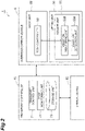
FIG. 2 is a block diagram illustrating a functional configuration of the overhead transport vehicle inFIG. 1 . -
FIG. 3 is one example of a detection result of a vibration detected by a vibration detection unit. -
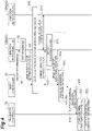
FIG. 4 is a sequence diagram illustrating flows of monitoring a vibration in the overhead transport vehicle inFIG. 1 . -
FIG. 5 is one example of a vibration monitoring screen output by a transport controller. - One preferred embodiment according to one aspect of the present invention will now be described in detail with reference to the drawings. In the description of the drawings, like elements are designated by like reference signs, and duplicate description is omitted.
- An overhead
transport vehicle system 1 according to the embodiment includes a plurality of overhead transport vehicles 6 (seeFIG. 1 ), atrack 4, and a transport controller 70 (seeFIG. 2 ). - As illustrated in
FIG. 1 , eachoverhead transport vehicle 6 according to the embodiment is an overhead transport vehicle movable along atrack 4, and is used for a system configured to carry a front opening unified pod (FOUP) (article) 10 between placement units (not illustrated). Theoverhead transport vehicle 6 may carry a container such as a reticle pod configured to store a plurality of glass substrates and also a general part, for example, instead of the FOUP 10. The following describes an example of theoverhead transport vehicles 6 used in the overheadtransport vehicle system 1 in which theoverhead transport vehicles 6 travel along the one-way track 4 installed on, for example, a ceiling of a factory. - The
track 4 is installed near the ceiling in a space overhead of an operator, for example. Thetrack 4 is suspended from the ceiling, for example. Thetrack 4 is a predetermined traveling path for theoverhead transport vehicles 6 to travel. Placement units are disposed along thetrack 4, and are provided at positions where eachoverhead transport vehicle 6 can deliver or receive aFOUP 10. Each placement unit includes a buffer and a delivery port. The buffer is a placement unit on which aFOUP 10 is temporarily placed. For example, the buffer is a placement unit on which aFOUP 10 being carried by anoverhead transport vehicle 6 is temporarily put when the FOUP 10 cannot be transferred onto a delivery port as a destination for the reason that, for example, anotherFOUP 10 has been placed on the delivery port. The delivery port is a placement unit for delivering and receiving aFOUP 10 to and from a semiconductor processing device (not illustrated) including cleaning equipment, deposition equipment, lithography equipment, etching equipment, thermal treatment equipment, and planarization equipment. Herein, the processing device is not limited to a particular one, and may be a device of various types. - Each
overhead transport vehicle 6 travels along thetrack 4 to carry aFOUP 10. Theoverhead transport vehicle 6 is an Overhead Hoist Transfer. The number of theoverhead transport vehicles 6 that the overheadtransport vehicle system 1 includes is not limited to a particular number, and is two or more. As illustrated inFIG. 1 andFIG. 2 , eachoverhead transport vehicle 6 includes atraveling unit 18, atransfer device 7, and a body controller (body control unit) 50. - The traveling
unit 18 includes a motor to cause theoverhead transport vehicle 6 to travel along thetrack 4. Thetransfer device 7 includes abody unit 22, across-feed unit 24, aθ drive 26, alifting drive unit 28, alifting unit 30, and front andrear frames - The
body unit 22 supports thecross-feed unit 24, theθ drive 26, thelifting drive unit 28, and thelifting unit 30. Thecross-feed unit 24 laterally feeds theθ drive 26, thelifting drive unit 28, and thelifting unit 30 all together in a direction orthogonal to the traveling direction of thetrack 4. Theθ drive 26 turns at least either one of thelifting drive unit 28 and thelifting unit 30 within a predetermined angle range in a horizontal plane. The liftingdrive unit 28 winds or pays out suspendingmembers 28A such as wires, ropes, and belts, thereby lifting or lowering the liftingunit 30. - The lifting
unit 30 is provided with a chuck (gripping part) 30A and asensor unit 55. Thechuck 30A holds a flange of aFOUP 10 in a manner supporting it from below. Thechuck 30A is configured to be capable of holding or releasing theFOUP 10. The fall prevention covers 33, 33 prevent theFOUP 10 from falling during transport by making claws (not illustrated) and the like not depicted appear and disappear. The front andrear frames overhead transport vehicle 6 in the traveling direction. - The
sensor unit 55 detects a vibration generated in the lifting unit 30 (i.e., a vibration generated in aFOUP 10 gripped by thechuck 30A) and outputs a detection result to thebody controller 50 described later in detail. Thesensor unit 55 includes avibration detection unit 55A configured to detect a vibration and avibration monitoring unit 55B. Thevibration detection unit 55A is, for example, a triaxial accelerometer and detects vibrations in an X-axis direction, a Y-axis direction, and a Z-axis direction. Thevibration detection unit 55A is provided at the center of gravity of the liftingunit 30 when the liftingunit 30 is viewed in plan view from the Z-axis direction. In the present embodiment, thevibration detection unit 55A is provided at a position adjacent to thechuck 30A. Thevibration detection unit 55A continuously detects vibrations in the X-axis direction, the Y-axis direction, and the Z-axis direction at predetermined intervals (seeFIG. 3 ). - The
vibration monitoring unit 55B determines whether a result of a vibration detected by thevibration detection unit 55A is within a predetermined permissible range R and also outputs this determination result to thebody controller 50. Thevibration monitoring unit 55B is an electronic control unit including a central processing unit (CPU), a read only memory (ROM), and a random access memory (RAM). Thevibration monitoring unit 55B can be configured, for example, as software such that a program stored in the ROM is loaded into the RAM to be executed by the CPU. Thevibration monitoring unit 55B may be configured as hardware such as an electronic circuit. - The permissible range R set in the
vibration monitoring unit 55B is set by thebody controller 50. Thevibration monitoring unit 55B of the present embodiment monitors a result of a vibration detected by thevibration detection unit 55A (seeFIG. 3 ) and, only when the above-described permissible range R has been exceeded, outputs a signal indicating that the permissible range has been exceeded to thebody controller 50. Specifically, at the points D indicated inFIG. 3 , thevibration monitoring unit 55B outputs signals indicating that the permissible range R has been exceeded to thebody controller 50. - The
vibration monitoring unit 55B outputs a determination result of a vibration during traveling and a determination result of a vibration during lifting or lowering of aFOUP 10 to thebody controller 50. In other words, in theoverhead transport vehicle 6 of the present embodiment, a vibration generated in thelifting unit 30 can be monitored both during traveling and during lifting or lowering. - The
vibration monitoring unit 55B is provided so as to be able to set a plurality of the permissible ranges R. For example, in thevibration monitoring unit 55B, a permissible range R1 during traveling on a straight track, a permissible range R2 during traveling on a curved track, and a permissible range R3 during lifting or lowering of a FOUP are included. Thevibration monitoring unit 55B is set such that the permissible ranges R1, R2, R3 switch depending on the operational state of theoverhead transport vehicle 6. - The
body controller 50 is an electronic control unit including a CPU, a ROM, and a RAM. Thebody controller 50 operates various operations of the respective units in the overhead transport vehicle 6 (i.e., the travelingunit 18 and the transfer device 7). Specifically, as illustrated inFIG. 2 , thebody controller 50 controls the travelingunit 18, thecross-feed unit 24, theθ drive 26, the liftingdrive unit 28, and thelifting unit 30. Thebody controller 50 can be configured, for example, as software such that a program stored in the ROM is loaded into the RAM to be executed by the CPU. Thebody controller 50 may be configured as hardware such as an electronic circuit. Thebody controller 50 and thesensor unit 55 are provided in a manner capable of communicating with each other by wire or radio. For communication by wire, a communication line is incorporated in the suspendingmembers 28A. - The
body controller 50 sets the permissible ranges R for thevibration monitoring unit 55B. Thebody controller 50 of the present embodiment sets each of the permissible range R1 during traveling on a straight track, the permissible range R2 during traveling on a curved track, and the permissible range R3 during lifting or lowering an article for thevibration monitoring unit 55B. - The
body controller 50 is capable of grasping the position of theoverhead transport vehicle 6 by appropriate means. For example, thebody controller 50 is capable of grasping the position of theoverhead transport vehicle 6 of itself on the basis of positional information acquired from a bar code or the like attached to thetrack 4 and a counter or the like of a motor, for example, included in the travelingunit 18. When having received a signal indicating that a permissible range R transmitted from thesensor unit 55 has been exceeded, thebody controller 50 stores this signal and the position of theoverhead transport vehicle 6 of itself in an associated manner in a memory (not illustrated), for example. In other words, thebody controller 50 stores information indicating a position where a vibration having exceeded the permissible range R (abnormal vibration) has been measured. Thebody controller 50 then transmits, to thetransport controller 70, the information indicating the position where the vibration having exceeded the permissible range R has been measured in response to a request from thetransport controller 70. - The
transport controller 70 illustrated inFIG. 2 controls theoverhead transport vehicles 6. Thetransport controller 70 is an electronic control unit including a CPU, a ROM, and a RAM. Thetransport controller 70 can be configured, for example, as software such that a program stored in the ROM is loaded into the RAM to be executed by the CPU. Thetransport controller 70 may be configured as hardware such as an electronic circuit. Thetransport controller 70 includes atransport control unit 71, astate monitoring unit 72, and astorage unit 73 that are configured by cooperative operation of hardware such as the CPU, the RAM, and the ROM and software such as a program. - The
transport control unit 71 assigns carriage instructions to theoverhead transport vehicles 6 on the basis of a carriage request from a host controller (not illustrated). Thestate monitoring unit 72 causes thebody controller 50 of eachoverhead transport vehicle 6 to transmit information indicating a position where a vibration has exceeded the permissible range R. Thestorage unit 73 stores a result of a determination performed by thevibration monitoring unit 55B and the position thereof on thetrack 4 in an associated manner. Specifically, thestorage unit 73 stores information, which is transmitted from thebody controller 50, indicating the position where the vibration (abnormal vibration) has exceeded the permissible range R. - The
state monitoring unit 72 of the present embodiment outputs the information stored in thestorage unit 73 to aterminal device 80. For example, thestate monitoring unit 72 causes theterminal device 80 to display a vibration monitoring screen SC1 as illustrated inFIG. 5 . The vibration monitoring screen SC1 is a screen in which the position A where an abnormal vibration has been generated is superimposed on a plan view of arrangement of thetrack 4. On this track plan view of thetrack 4, stockers and the like (rectangular figures displayed along the track 4) are displayed in addition to thetrack 4. - The following describes operation of the overhead
transport vehicle system 1 in the present embodiment, mainly with reference toFIG. 4 . To begin with, thebody controller 50 transmits a threshold for setting a permissible range R of a vibration to thevibration monitoring unit 55B (step S1). Thevibration monitoring unit 55B having received the threshold from thebody controller 50 sets the permissible range R (threshold) (step S2). Thevibration monitoring unit 55B transmits a notice of having set the permissible range R to the body controller 50 (step S3). By these processes, preparation for monitoring a vibration in thesensor unit 55, that is, preparation for, when a vibration detected by thevibration detection unit 55A has exceeded the permissible range R (when an abnormal vibration has been detected), outputting a signal indicating this excess is completed (step S10). - When the preparation for monitoring a vibration in the
sensor unit 55 has been completed, thevibration detection unit 55A detects a vibration generated in thelifting unit 30 at predetermined intervals. Thevibration monitoring unit 55B and thevibration detection unit 55A consecutively communicate data therebetween, and thevibration monitoring unit 55B monitors a vibration detected by thevibration detection unit 55A (step S11). Thebody controller 50 consecutively checks whether the vibration exceeds the permissible range R (step S12). Herein, when having detected that a vibration value detected by thevibration detection unit 55A has exceeded the permissible range R (step S13), thevibration detection unit 55A transmits information on this excess to the body controller 50 (step S14). - When having received a signal indicating that the permissible range R transmitted from the
vibration monitoring unit 55B has been exceeded (step S15), thebody controller 50 stores abnormal vibration information, in which the signal indicating this excess and the position on thetrack 4 are associated with each other, in a memory (not illustrated), for example. Thetransport controller 70 periodically inquires thebody controller 50 about the state of the overhead transport vehicle 6 (step S16). When thebody controller 50 has received each of the periodic inquiries from thetransport controller 70, if abnormal vibration information (vibration detection log) has been stored (accumulated), thebody controller 50 outputs this abnormal vibration information to the transport controller 70 (step S20). - When having received the abnormal vibration information output from the
body controller 50, thetransport controller 70 stores the abnormal vibration information in the storage unit 73 (step S21). Thetransport controller 70 then outputs the abnormal vibration information stored in thestorage unit 73 to the terminal device 80 (step S22). Examples of theterminal device 80 include a display, a mobile terminal, a smart phone, and a tablet. Theterminal device 80 displays the abnormal vibration information transmitted from thetransport controller 70 as the vibration monitoring screen SC1 as illustrated inFIG. 5 . - In each
overhead transport vehicle 6 of the above-described embodiment, only the result of a determining whether the result of a vibration detected by thevibration detection unit 55A has exceeded the predetermined permissible range R is output from thevibration monitoring unit 55B to thebody controller 50. Thus, the processing load in thebody controller 50 can be reduced more than in a configuration in which all of the detection results detected by thesensor unit 55 are output to thebody controller 50. Furthermore, in theoverhead transport vehicle 6 of the embodiment, whether a vibration detected by thevibration detection unit 55A is within the predetermined permissible range R is simply determined, and thus a vibration generated in aFOUP 10 can be monitored with a simple configuration without performing advanced analysis and the like. Consequently, a vibration generated in aFOUP 10 gripped by the liftingunit 30 can be monitored with a simple configuration without increasing processing load in thebody controller 50 equipped on theoverhead transport vehicle 6. - In the
overhead transport vehicle 6 of the embodiment, thebody controller 50 can set the permissible range R for thevibration monitoring unit 55B. By this configuration, the permissible range R for determining an abnormal vibration can be easily set. - In the
overhead transport vehicle 6 of the embodiment, when having determined that a vibration detected by thevibration detection unit 55A has exceeded the permissible range R, thevibration monitoring unit 55B outputs a signal indicating this excess to thebody controller 50. In this configuration, only when a vibration detected by thevibration detection unit 55A has been determined to have exceeded the permissible range R, that is, only when an abnormal vibration has been determined to have been detected, thevibration monitoring unit 55B outputs the signal indicating this excess to thebody controller 50, and thus the processing load in thebody controller 50 can be further reduced. - In the
overhead transport vehicle 6 of the embodiment, thevibration monitoring unit 55B outputs, to thebody controller 50, both of a result of a determination on a vibration during traveling and a result of a determination on a vibration during lifting or lowering of aFOUP 10. In this configuration, it is possible to monitor both of an abnormal vibration when theoverhead transport vehicle 6 is traveling and an abnormal vibration when the liftingunit 30 is performing lifting or lowering operation while theoverhead transport vehicle 6 stops. - In the
overhead transport vehicle 6 according to the embodiment, thevibration monitoring unit 55B is provided so as to be able to set a plurality of permissible ranges, and is set such that the permissible ranges switch depending on the operational state of theoverhead transport vehicle 6. In this configuration, an abnormal vibration depending on the operational state of theoverhead transport vehicle 6 can be suitably detected. - In the overhead
transport vehicle system 1 of the embodiment, an abnormal vibration (indicating that a vibration has exceeded the permissible range) and the position where the abnormal vibration has been generated are stored so as to be associated with each other, and thus the location of this abnormality on thetrack 4 can be easily grasped. Furthermore, in the embodiment, vibration information stored in thestorage unit 73 is displayed as the vibration monitoring screen SC1 as illustrated inFIG. 5 , and thus information that can be visually grasped can be provided. - Although one embodiment according to one aspect of the present invention has been described above, the aspect of the present invention is not limited to the embodiment, and various modifications may be made within the scope not departing from the gist of the invention.
- In the embodiment, an example has been described in which the permissible ranges R1, R2, R3 are set by the
body controller 50. However, the number of the permissible ranges is not limited to this, and may be one, two, or four or more. - In the embodiment and the modification above, an example has been described in which, only when a vibration detected by the
vibration detection unit 55A has exceeded the permissible range R, thevibration monitoring unit 55B outputs a signal indicating this excess to thebody controller 50. However, thevibration monitoring unit 55B may periodically output information (signal) on whether the permissible range R has been exceeded to thebody controller 50. - In the embodiment and the modifications above, an example has been described in which the
body controller 50 can set the permissible range R for thevibration monitoring unit 55B. However, thebody controller 50 may be configured to be incapable of making the setting. In this case, the permissible range R may be set in advance in thevibration monitoring unit 55B, or may be configured to be switchable by a switch, for example, provided at thevibration monitoring unit 55B. - In the embodiment and the modifications above, an example has been described in which the
state monitoring unit 72 configured to output information in which the determination result is superimposed on map data indicating the arrangement of thetrack 4 is configured in thetransport controller 70. However, an additional independent controller may be provided, and a controller having the above-described functions may be provided in oneoverhead transport vehicle 6 out of theoverhead transport vehicles 6. - 1 ... overhead transport vehicle system, 4 ... track, 6 ... overhead transport vehicle, 18 ... traveling unit, 22 ... body unit, 28A ... suspending member, 30 ... lifting unit, 30A ... chuck (gripping part), 50 ... body controller (body control unit), 55 ... sensor unit, 55A ... vibration detection unit, 55B ... vibration monitoring unit, 70 ... transport controller, 71 ... transport control unit, 72 ... state monitoring unit, 73 ... storage unit, R, R1, R2, R3 ... permissible range, SC1 ... vibration monitoring screen
Claims (6)
- An overhead transport vehicle including a body unit capable of traveling along a track, and a lifting unit including a gripping part configured to grip an article and configured to ascend and descend with respect to the body unit by a suspending member, the overhead transport vehicle comprising:a body control unit provided in the body unit and configured to control respective units in the overhead transport vehicle;a vibration detection unit provided in the lifting unit and configured to detect a vibration generated in the lifting unit; anda vibration monitoring unit provided in the lifting unit and configured to determine whether a result of the vibration detected by the vibration detection unit is within a predetermined permissible range and also output a result of the determination to the body control unit.
- The overhead transport vehicle according to claim 1, wherein the body control unit sets the permissible range for the vibration monitoring unit.
- The overhead transport vehicle according to claim 1 or 2, wherein the vibration monitoring unit outputs a notice of this excess to the body control unit when a vibration detected by the vibration detection unit has exceeded the permissible range.
- The overhead transport vehicle according to claim 1, wherein the vibration monitoring unit outputs, to the body control unit, at least one of a result of a determination on the vibration during traveling and a result of a determination on the vibration during lifting or lowering of the article.
- The overhead transport vehicle according to any one of claims 1 to 3, wherein the vibration monitoring unit is provided so as to be able to set a plurality of permissible ranges, and is set such that the permissible ranges switch depending on an operational state of the overhead transport vehicle.
- An overhead transport vehicle system comprising:a plurality of the overhead transport vehicles according to any one of claims 1 to 5; anda state monitoring unit provided in a manner capable of communicating with the body control unit of each of the overhead transport vehicles, whereinthe state monitoring unit stores therein a result of a determination performed by the vibration monitoring unit and a position on the track in an associated manner and also outputs information in which the result of the determination is superimposed on map data representing an arrangement of the track.
Applications Claiming Priority (2)
| Application Number | Priority Date | Filing Date | Title |
|---|---|---|---|
| JP2019155943 | 2019-08-28 | ||
| PCT/JP2020/024862 WO2021039077A1 (en) | 2019-08-28 | 2020-06-24 | Overhead carrier vehicle and overhead carrier vehicle system |
Publications (3)
| Publication Number | Publication Date |
|---|---|
| EP4023568A1 true EP4023568A1 (en) | 2022-07-06 |
| EP4023568A4 EP4023568A4 (en) | 2023-08-23 |
| EP4023568B1 EP4023568B1 (en) | 2024-08-28 |
Family
ID=74685832
Family Applications (1)
| Application Number | Title | Priority Date | Filing Date |
|---|---|---|---|
| EP20857924.3A Active EP4023568B1 (en) | 2019-08-28 | 2020-06-24 | Overhead carrier vehicle and overhead carrier vehicle system |
Country Status (8)
| Country | Link |
|---|---|
| US (1) | US12043498B2 (en) |
| EP (1) | EP4023568B1 (en) |
| JP (1) | JP7168096B2 (en) |
| KR (1) | KR102659882B1 (en) |
| CN (1) | CN114245935B (en) |
| IL (1) | IL290646B2 (en) |
| TW (1) | TWI839564B (en) |
| WO (1) | WO2021039077A1 (en) |
Cited By (1)
| Publication number | Priority date | Publication date | Assignee | Title |
|---|---|---|---|---|
| WO2024083748A1 (en) * | 2022-10-18 | 2024-04-25 | Ocado Innovation Limited | Method and system for detecting track defects |
Families Citing this family (7)
| Publication number | Priority date | Publication date | Assignee | Title |
|---|---|---|---|---|
| JP7651164B2 (en) * | 2021-05-25 | 2025-03-26 | 株式会社LoPAS | Information display device |
| CN118056113A (en) * | 2021-08-17 | 2024-05-17 | 图森有限公司 | Determine the mechanical health and road conditions encountered by autonomous vehicles |
| WO2023084940A1 (en) * | 2021-11-11 | 2023-05-19 | 村田機械株式会社 | Overhead conveying vehicle |
| CN114455454B (en) * | 2022-01-26 | 2023-03-21 | 弥费科技(上海)股份有限公司 | Lifting mechanism control method and system of air transport vehicle |
| WO2024214441A1 (en) * | 2023-04-10 | 2024-10-17 | 村田機械株式会社 | Overhead transport vehicle system and overhead transport vehicle |
| JP7816291B2 (en) * | 2023-06-07 | 2026-02-18 | 株式会社ダイフク | Information Display System |
| TWI868970B (en) * | 2023-10-06 | 2025-01-01 | 迅得機械股份有限公司 | Rail vehicle monitoring management system and management method thereof |
Family Cites Families (13)
| Publication number | Priority date | Publication date | Assignee | Title |
|---|---|---|---|---|
| TW568879B (en) * | 1998-04-01 | 2004-01-01 | Asyst Shinko Inc | Suspension type hoist |
| KR20050028447A (en) * | 2003-09-18 | 2005-03-23 | 엘지.필립스 엘시디 주식회사 | Unbalance measuring instrument of using auto guided vehicle and method for measuring using the same |
| JP2006315813A (en) | 2005-05-13 | 2006-11-24 | Murata Mach Ltd | Mobile diagnostic system |
| JP4117625B2 (en) * | 2005-05-26 | 2008-07-16 | 村田機械株式会社 | Transport vehicle system |
| JP2009249053A (en) * | 2008-04-01 | 2009-10-29 | Murata Mach Ltd | Automated warehouse |
| CN104428217A (en) * | 2012-07-26 | 2015-03-18 | 村田机械株式会社 | Overhead traveling vehicle system and control method for overhead traveling vehicle system |
| JP6079672B2 (en) * | 2014-03-10 | 2017-02-15 | 村田機械株式会社 | Transport vehicle system |
| KR102502235B1 (en) | 2015-07-16 | 2023-02-21 | 삼성전자주식회사 | Logistic monitoring system and the method |
| KR101702779B1 (en) | 2015-10-29 | 2017-02-03 | 세메스 주식회사 | Hand unit of overhead hoist transport |
| JP6471702B2 (en) * | 2016-01-12 | 2019-02-20 | 株式会社ダイフク | Article conveying device |
| WO2017178712A1 (en) * | 2016-04-15 | 2017-10-19 | Conexbird Oy | A method, software, and an apparatus for inspection of shipments |
| JP6545396B2 (en) * | 2016-09-29 | 2019-07-17 | 株式会社Kokusai Electric | Substrate processing apparatus, vibration detection system and program |
| JP6819224B2 (en) * | 2016-10-31 | 2021-01-27 | 株式会社ダイフク | Transport vehicle |
-
2020
- 2020-06-24 EP EP20857924.3A patent/EP4023568B1/en active Active
- 2020-06-24 KR KR1020227009763A patent/KR102659882B1/en active Active
- 2020-06-24 CN CN202080057841.XA patent/CN114245935B/en active Active
- 2020-06-24 WO PCT/JP2020/024862 patent/WO2021039077A1/en not_active Ceased
- 2020-06-24 IL IL290646A patent/IL290646B2/en unknown
- 2020-06-24 US US17/636,046 patent/US12043498B2/en active Active
- 2020-06-24 JP JP2021542050A patent/JP7168096B2/en active Active
- 2020-08-26 TW TW109129041A patent/TWI839564B/en active
Cited By (1)
| Publication number | Priority date | Publication date | Assignee | Title |
|---|---|---|---|---|
| WO2024083748A1 (en) * | 2022-10-18 | 2024-04-25 | Ocado Innovation Limited | Method and system for detecting track defects |
Also Published As
| Publication number | Publication date |
|---|---|
| EP4023568A4 (en) | 2023-08-23 |
| US20220332522A1 (en) | 2022-10-20 |
| IL290646A (en) | 2022-04-01 |
| KR102659882B1 (en) | 2024-04-24 |
| IL290646B1 (en) | 2025-02-01 |
| KR20220047872A (en) | 2022-04-19 |
| TWI839564B (en) | 2024-04-21 |
| JP7168096B2 (en) | 2022-11-09 |
| CN114245935A (en) | 2022-03-25 |
| IL290646B2 (en) | 2025-06-01 |
| TW202128541A (en) | 2021-08-01 |
| CN114245935B (en) | 2025-07-04 |
| JPWO2021039077A1 (en) | 2021-03-04 |
| WO2021039077A1 (en) | 2021-03-04 |
| EP4023568B1 (en) | 2024-08-28 |
| US12043498B2 (en) | 2024-07-23 |
Similar Documents
| Publication | Publication Date | Title |
|---|---|---|
| EP4023568B1 (en) | Overhead carrier vehicle and overhead carrier vehicle system | |
| EP3389084A1 (en) | Conveyance system and conveyance method | |
| EP2916345B1 (en) | Communication device, communication equipment and communication system | |
| EP3159922B1 (en) | Carrier transport system and transport method | |
| EP3988474A1 (en) | Conveyance vehicle | |
| US12466645B2 (en) | Traveling vehicle system and traveling vehicle control method | |
| US11958689B2 (en) | Vehicle system | |
| US10354902B2 (en) | Conveyance system | |
| EP3159921B1 (en) | Carrier buffering device and storage method | |
| CN116234766A (en) | Remote automatic RTG system, control method of remote automatic RTG system and control device of remote automatic RTG system | |
| CN117916175A (en) | Overhead conveyor | |
| WO2022102254A1 (en) | Conveyance vehicle system | |
| US20250219920A1 (en) | Conveyance system | |
| US12518626B2 (en) | Traveling vehicle system | |
| TW202329312A (en) | Conveyor system | |
| US20250157840A1 (en) | Transport system | |
| KR20110033882A (en) | Wafer Carrier Voice Alert Device for Semiconductor Wafer Carrier Auto Carrier | |
| JP7192345B2 (en) | carrier system | |
| WO2025164000A1 (en) | Conveyance system | |
| KR20160059607A (en) | Apparatus for ahead warning system of automatic transfer equipment | |
| JP2022096752A (en) | Elevator system |
Legal Events
| Date | Code | Title | Description |
|---|---|---|---|
| STAA | Information on the status of an ep patent application or granted ep patent |
Free format text: STATUS: THE INTERNATIONAL PUBLICATION HAS BEEN MADE |
|
| PUAI | Public reference made under article 153(3) epc to a published international application that has entered the european phase |
Free format text: ORIGINAL CODE: 0009012 |
|
| STAA | Information on the status of an ep patent application or granted ep patent |
Free format text: STATUS: REQUEST FOR EXAMINATION WAS MADE |
|
| 17P | Request for examination filed |
Effective date: 20220315 |
|
| AK | Designated contracting states |
Kind code of ref document: A1 Designated state(s): AL AT BE BG CH CY CZ DE DK EE ES FI FR GB GR HR HU IE IS IT LI LT LU LV MC MK MT NL NO PL PT RO RS SE SI SK SM TR |
|
| DAV | Request for validation of the european patent (deleted) | ||
| DAX | Request for extension of the european patent (deleted) | ||
| REG | Reference to a national code |
Ref country code: DE Ref legal event code: R079 Free format text: PREVIOUS MAIN CLASS: B65G0001000000 Ipc: H01L0021677000 Ref country code: DE Ref legal event code: R079 Ref document number: 602020036846 Country of ref document: DE Free format text: PREVIOUS MAIN CLASS: B65G0001000000 Ipc: H01L0021677000 |
|
| A4 | Supplementary search report drawn up and despatched |
Effective date: 20230724 |
|
| RIC1 | Information provided on ipc code assigned before grant |
Ipc: H01L 21/67 20060101ALI20230718BHEP Ipc: H01L 21/677 20060101AFI20230718BHEP |
|
| GRAP | Despatch of communication of intention to grant a patent |
Free format text: ORIGINAL CODE: EPIDOSNIGR1 |
|
| STAA | Information on the status of an ep patent application or granted ep patent |
Free format text: STATUS: GRANT OF PATENT IS INTENDED |
|
| INTG | Intention to grant announced |
Effective date: 20240404 |
|
| RIN1 | Information on inventor provided before grant (corrected) |
Inventor name: AOMOTO, KAZUYA |
|
| GRAS | Grant fee paid |
Free format text: ORIGINAL CODE: EPIDOSNIGR3 |
|
| GRAA | (expected) grant |
Free format text: ORIGINAL CODE: 0009210 |
|
| STAA | Information on the status of an ep patent application or granted ep patent |
Free format text: STATUS: THE PATENT HAS BEEN GRANTED |
|
| AK | Designated contracting states |
Kind code of ref document: B1 Designated state(s): AL AT BE BG CH CY CZ DE DK EE ES FI FR GB GR HR HU IE IS IT LI LT LU LV MC MK MT NL NO PL PT RO RS SE SI SK SM TR |
|
| REG | Reference to a national code |
Ref country code: CH Ref legal event code: EP |
|
| REG | Reference to a national code |
Ref country code: DE Ref legal event code: R096 Ref document number: 602020036846 Country of ref document: DE |
|
| REG | Reference to a national code |
Ref country code: IE Ref legal event code: FG4D |
|
| REG | Reference to a national code |
Ref country code: LT Ref legal event code: MG9D |
|
| PG25 | Lapsed in a contracting state [announced via postgrant information from national office to epo] |
Ref country code: NO Free format text: LAPSE BECAUSE OF FAILURE TO SUBMIT A TRANSLATION OF THE DESCRIPTION OR TO PAY THE FEE WITHIN THE PRESCRIBED TIME-LIMIT Effective date: 20241128 |
|
| REG | Reference to a national code |
Ref country code: AT Ref legal event code: MK05 Ref document number: 1718961 Country of ref document: AT Kind code of ref document: T Effective date: 20240828 |
|
| PG25 | Lapsed in a contracting state [announced via postgrant information from national office to epo] |
Ref country code: NL Free format text: LAPSE BECAUSE OF FAILURE TO SUBMIT A TRANSLATION OF THE DESCRIPTION OR TO PAY THE FEE WITHIN THE PRESCRIBED TIME-LIMIT Effective date: 20240828 Ref country code: PT Free format text: LAPSE BECAUSE OF FAILURE TO SUBMIT A TRANSLATION OF THE DESCRIPTION OR TO PAY THE FEE WITHIN THE PRESCRIBED TIME-LIMIT Effective date: 20241230 Ref country code: PL Free format text: LAPSE BECAUSE OF FAILURE TO SUBMIT A TRANSLATION OF THE DESCRIPTION OR TO PAY THE FEE WITHIN THE PRESCRIBED TIME-LIMIT Effective date: 20240828 Ref country code: GR Free format text: LAPSE BECAUSE OF FAILURE TO SUBMIT A TRANSLATION OF THE DESCRIPTION OR TO PAY THE FEE WITHIN THE PRESCRIBED TIME-LIMIT Effective date: 20241129 Ref country code: FI Free format text: LAPSE BECAUSE OF FAILURE TO SUBMIT A TRANSLATION OF THE DESCRIPTION OR TO PAY THE FEE WITHIN THE PRESCRIBED TIME-LIMIT Effective date: 20240828 |
|
| PG25 | Lapsed in a contracting state [announced via postgrant information from national office to epo] |
Ref country code: BG Free format text: LAPSE BECAUSE OF FAILURE TO SUBMIT A TRANSLATION OF THE DESCRIPTION OR TO PAY THE FEE WITHIN THE PRESCRIBED TIME-LIMIT Effective date: 20240828 |
|
| PG25 | Lapsed in a contracting state [announced via postgrant information from national office to epo] |
Ref country code: LV Free format text: LAPSE BECAUSE OF FAILURE TO SUBMIT A TRANSLATION OF THE DESCRIPTION OR TO PAY THE FEE WITHIN THE PRESCRIBED TIME-LIMIT Effective date: 20240828 |
|
| REG | Reference to a national code |
Ref country code: NL Ref legal event code: MP Effective date: 20240828 |
|
| PG25 | Lapsed in a contracting state [announced via postgrant information from national office to epo] |
Ref country code: AT Free format text: LAPSE BECAUSE OF FAILURE TO SUBMIT A TRANSLATION OF THE DESCRIPTION OR TO PAY THE FEE WITHIN THE PRESCRIBED TIME-LIMIT Effective date: 20240828 Ref country code: IS Free format text: LAPSE BECAUSE OF FAILURE TO SUBMIT A TRANSLATION OF THE DESCRIPTION OR TO PAY THE FEE WITHIN THE PRESCRIBED TIME-LIMIT Effective date: 20241228 |
|
| PG25 | Lapsed in a contracting state [announced via postgrant information from national office to epo] |
Ref country code: HR Free format text: LAPSE BECAUSE OF FAILURE TO SUBMIT A TRANSLATION OF THE DESCRIPTION OR TO PAY THE FEE WITHIN THE PRESCRIBED TIME-LIMIT Effective date: 20240828 |
|
| PG25 | Lapsed in a contracting state [announced via postgrant information from national office to epo] |
Ref country code: RS Free format text: LAPSE BECAUSE OF FAILURE TO SUBMIT A TRANSLATION OF THE DESCRIPTION OR TO PAY THE FEE WITHIN THE PRESCRIBED TIME-LIMIT Effective date: 20241128 Ref country code: ES Free format text: LAPSE BECAUSE OF FAILURE TO SUBMIT A TRANSLATION OF THE DESCRIPTION OR TO PAY THE FEE WITHIN THE PRESCRIBED TIME-LIMIT Effective date: 20240828 |
|
| PG25 | Lapsed in a contracting state [announced via postgrant information from national office to epo] |
Ref country code: RS Free format text: LAPSE BECAUSE OF FAILURE TO SUBMIT A TRANSLATION OF THE DESCRIPTION OR TO PAY THE FEE WITHIN THE PRESCRIBED TIME-LIMIT Effective date: 20241128 Ref country code: PT Free format text: LAPSE BECAUSE OF FAILURE TO SUBMIT A TRANSLATION OF THE DESCRIPTION OR TO PAY THE FEE WITHIN THE PRESCRIBED TIME-LIMIT Effective date: 20241230 Ref country code: PL Free format text: LAPSE BECAUSE OF FAILURE TO SUBMIT A TRANSLATION OF THE DESCRIPTION OR TO PAY THE FEE WITHIN THE PRESCRIBED TIME-LIMIT Effective date: 20240828 Ref country code: NO Free format text: LAPSE BECAUSE OF FAILURE TO SUBMIT A TRANSLATION OF THE DESCRIPTION OR TO PAY THE FEE WITHIN THE PRESCRIBED TIME-LIMIT Effective date: 20241128 Ref country code: NL Free format text: LAPSE BECAUSE OF FAILURE TO SUBMIT A TRANSLATION OF THE DESCRIPTION OR TO PAY THE FEE WITHIN THE PRESCRIBED TIME-LIMIT Effective date: 20240828 Ref country code: LV Free format text: LAPSE BECAUSE OF FAILURE TO SUBMIT A TRANSLATION OF THE DESCRIPTION OR TO PAY THE FEE WITHIN THE PRESCRIBED TIME-LIMIT Effective date: 20240828 Ref country code: IS Free format text: LAPSE BECAUSE OF FAILURE TO SUBMIT A TRANSLATION OF THE DESCRIPTION OR TO PAY THE FEE WITHIN THE PRESCRIBED TIME-LIMIT Effective date: 20241228 Ref country code: HR Free format text: LAPSE BECAUSE OF FAILURE TO SUBMIT A TRANSLATION OF THE DESCRIPTION OR TO PAY THE FEE WITHIN THE PRESCRIBED TIME-LIMIT Effective date: 20240828 Ref country code: GR Free format text: LAPSE BECAUSE OF FAILURE TO SUBMIT A TRANSLATION OF THE DESCRIPTION OR TO PAY THE FEE WITHIN THE PRESCRIBED TIME-LIMIT Effective date: 20241129 Ref country code: FI Free format text: LAPSE BECAUSE OF FAILURE TO SUBMIT A TRANSLATION OF THE DESCRIPTION OR TO PAY THE FEE WITHIN THE PRESCRIBED TIME-LIMIT Effective date: 20240828 Ref country code: ES Free format text: LAPSE BECAUSE OF FAILURE TO SUBMIT A TRANSLATION OF THE DESCRIPTION OR TO PAY THE FEE WITHIN THE PRESCRIBED TIME-LIMIT Effective date: 20240828 Ref country code: BG Free format text: LAPSE BECAUSE OF FAILURE TO SUBMIT A TRANSLATION OF THE DESCRIPTION OR TO PAY THE FEE WITHIN THE PRESCRIBED TIME-LIMIT Effective date: 20240828 Ref country code: AT Free format text: LAPSE BECAUSE OF FAILURE TO SUBMIT A TRANSLATION OF THE DESCRIPTION OR TO PAY THE FEE WITHIN THE PRESCRIBED TIME-LIMIT Effective date: 20240828 |
|
| PG25 | Lapsed in a contracting state [announced via postgrant information from national office to epo] |
Ref country code: DK Free format text: LAPSE BECAUSE OF FAILURE TO SUBMIT A TRANSLATION OF THE DESCRIPTION OR TO PAY THE FEE WITHIN THE PRESCRIBED TIME-LIMIT Effective date: 20240828 Ref country code: RO Free format text: LAPSE BECAUSE OF FAILURE TO SUBMIT A TRANSLATION OF THE DESCRIPTION OR TO PAY THE FEE WITHIN THE PRESCRIBED TIME-LIMIT Effective date: 20240828 Ref country code: SM Free format text: LAPSE BECAUSE OF FAILURE TO SUBMIT A TRANSLATION OF THE DESCRIPTION OR TO PAY THE FEE WITHIN THE PRESCRIBED TIME-LIMIT Effective date: 20240828 |
|
| PG25 | Lapsed in a contracting state [announced via postgrant information from national office to epo] |
Ref country code: EE Free format text: LAPSE BECAUSE OF FAILURE TO SUBMIT A TRANSLATION OF THE DESCRIPTION OR TO PAY THE FEE WITHIN THE PRESCRIBED TIME-LIMIT Effective date: 20240828 |
|
| PG25 | Lapsed in a contracting state [announced via postgrant information from national office to epo] |
Ref country code: CZ Free format text: LAPSE BECAUSE OF FAILURE TO SUBMIT A TRANSLATION OF THE DESCRIPTION OR TO PAY THE FEE WITHIN THE PRESCRIBED TIME-LIMIT Effective date: 20240828 |
|
| PG25 | Lapsed in a contracting state [announced via postgrant information from national office to epo] |
Ref country code: SK Free format text: LAPSE BECAUSE OF FAILURE TO SUBMIT A TRANSLATION OF THE DESCRIPTION OR TO PAY THE FEE WITHIN THE PRESCRIBED TIME-LIMIT Effective date: 20240828 Ref country code: IT Free format text: LAPSE BECAUSE OF FAILURE TO SUBMIT A TRANSLATION OF THE DESCRIPTION OR TO PAY THE FEE WITHIN THE PRESCRIBED TIME-LIMIT Effective date: 20240828 |
|
| REG | Reference to a national code |
Ref country code: DE Ref legal event code: R097 Ref document number: 602020036846 Country of ref document: DE |
|
| PLBE | No opposition filed within time limit |
Free format text: ORIGINAL CODE: 0009261 |
|
| STAA | Information on the status of an ep patent application or granted ep patent |
Free format text: STATUS: NO OPPOSITION FILED WITHIN TIME LIMIT |
|
| PGFP | Annual fee paid to national office [announced via postgrant information from national office to epo] |
Ref country code: DE Payment date: 20250520 Year of fee payment: 6 |
|
| PGFP | Annual fee paid to national office [announced via postgrant information from national office to epo] |
Ref country code: IE Payment date: 20250522 Year of fee payment: 6 |
|
| 26N | No opposition filed |
Effective date: 20250530 |
|
| PG25 | Lapsed in a contracting state [announced via postgrant information from national office to epo] |
Ref country code: SE Free format text: LAPSE BECAUSE OF FAILURE TO SUBMIT A TRANSLATION OF THE DESCRIPTION OR TO PAY THE FEE WITHIN THE PRESCRIBED TIME-LIMIT Effective date: 20240828 |
|
| REG | Reference to a national code |
Ref country code: DE Ref legal event code: R079 Ref document number: 602020036846 Country of ref document: DE Free format text: PREVIOUS MAIN CLASS: H01L0021677000 Ipc: H10P0072300000 |
|
| REG | Reference to a national code |
Ref country code: CH Ref legal event code: H13 Free format text: ST27 STATUS EVENT CODE: U-0-0-H10-H13 (AS PROVIDED BY THE NATIONAL OFFICE) Effective date: 20260127 |
|
| PG25 | Lapsed in a contracting state [announced via postgrant information from national office to epo] |
Ref country code: MC Free format text: LAPSE BECAUSE OF FAILURE TO SUBMIT A TRANSLATION OF THE DESCRIPTION OR TO PAY THE FEE WITHIN THE PRESCRIBED TIME-LIMIT Effective date: 20240828 |
|
| PG25 | Lapsed in a contracting state [announced via postgrant information from national office to epo] |
Ref country code: LU Free format text: LAPSE BECAUSE OF NON-PAYMENT OF DUE FEES Effective date: 20250624 |
|
| GBPC | Gb: european patent ceased through non-payment of renewal fee |
Effective date: 20250624 |
|
| REG | Reference to a national code |
Ref country code: BE Ref legal event code: MM Effective date: 20250630 |
|
| PG25 | Lapsed in a contracting state [announced via postgrant information from national office to epo] |
Ref country code: GB Free format text: LAPSE BECAUSE OF NON-PAYMENT OF DUE FEES Effective date: 20250624 |
|
| PG25 | Lapsed in a contracting state [announced via postgrant information from national office to epo] |
Ref country code: BE Free format text: LAPSE BECAUSE OF NON-PAYMENT OF DUE FEES Effective date: 20250630 |
|
| PG25 | Lapsed in a contracting state [announced via postgrant information from national office to epo] |
Ref country code: FR Free format text: LAPSE BECAUSE OF NON-PAYMENT OF DUE FEES Effective date: 20250630 |
|
| PG25 | Lapsed in a contracting state [announced via postgrant information from national office to epo] |
Ref country code: CH Free format text: LAPSE BECAUSE OF NON-PAYMENT OF DUE FEES Effective date: 20250630 |